


 Loading...
EDN Series Mini Dome IP Camera
H.264, East Installation, Micro SD Card, Night Vision
User’s Manual
Copyright © EverFocus Electronics Corp,
Release Date: October, 2013

Copyright 2013 EverFocus Electronics Corp.
All rights reserved. No part of the contents of this manual may be reproduced or transmitted in any form or by any means without written permission of the EverFocus Electronics Corporation.
EverFocus
12F, No.79, Sec. 1, Shin-Tai Wu Road, Hsi-Chih, Taipei, Taiwan
TEL: +886 2 2698 2334
FAX: +886 2 2698 2380 www.everfocus.com.tw
October, 2013
About this document
All the safety and operating instructions should be read and followed before the unit is operated. This manual should be retained for future reference. The information in this manual was current when published. The manufacturer reserves the right to revise and improve its products. All specifications are therefore subject to change without notice.
Regulatory Notices
FCC Notice "Declaration of Conformity Information"
This equipment has been tested and found to comply with the limits for a Class
A digital device, pursuant to part 15 of the FCC Rules. These limits are designed to provide reasonable protection against harmful interference in a residential installation. This equipment generates, uses and can radiate radio frequency energy and, if not installed and used in accordance with the instructions, may cause harmful interference to radio communications. However, there is no guarantee that interference will not occur in a particular installation. If this equipment does cause harmful interference to radio or television reception, which can be determined by turning the equipment off and on, the user is encouraged to try to correct the interference by one or more of the following measures:
-Reorient or relocate the receiving antenna.
-Increase the separation between the equipment and receiver.
-Connect the equipment into an outlet on a circuit different from that to which the receiver is connected.
-Consult the dealer or an experienced radio/TV technician for help.
Warning: Changes or modifications made to this equipment, not expressly approved by EverFocus or parties authorized by EverFocus could void the user's authority to operate the equipment.
This device complies with part 15 of the FCC Rules. Operation is subject to the following two conditions:
(1)This device may not cause harmful interference, and
(2)This device must accept any interference received, including interference that may cause undesired operation.
EverFocus Electronics Corp.
12F, No. 79, Sec. 1, Shin-Tai Wu Rd., Hsi-Chi,
Taipei Hsien, Taiwan, R.O.C.
EDN Series cameras comply with CE and FCC.
i
Precautions
1. Do not install the camera near electric or magnetic fields.
Install the camera away from TV/radio transmitters, magnets, electric motors, transformers and audio speakers since the electromagnetic fields generated from these devices may distort the video image or otherwise interfere with camera operation.
2.Never disassemble the camera beyond the recommendations in this manual nor introduce materials other than those recommended herein.
Improper disassembly or introduction of corrosive materials may result in equipment failure or other damage.
3.Try to avoid facing the camera toward the sun.
In some circumstances, direct sunlight may cause permanent damage to the sensor and/or internal circuits, as well as creating unbalanced illumination beyond the capability of the camera to compensate.
4.Keep the power cord away from water and other liquids and never touch the power cord with wet hands.
Touching a wet power cord with your hands or touching the power cord with wet hands may result in electric shock.
5.Never install the camera in areas exposed to oil, gas or solvents.
Oil, gas or solvents may result in equipment failure, electric shock or, in extreme cases, fire.
6. Cleaning
For cameras with interchangeable lenses, do not touch the surface of the sensor directly with the hands. Use lens tissue or a cotton tipped applicator and ethanol to clean the sensor and the camera lens. Use a damp soft cloth to remove any dirt from the camera body. Please do not use complex solvents, corrosive or abrasive agents for cleaning of any part of the camera.
7.Do not operate the camera beyond the specified temperature, humidity or power source ratings.
This camera is suitable for outdoor operation only. Use the camera at temperatures within 0°C~40°C/32°F~104°F. The input power source is 12 VDC/PoE. Be sure to connect the proper + / - polarity and voltage, as incorrect polarity or too high a voltage will likely cause the camera to fail, and such damage is not covered by the warranty. The use of properly fused or Class 2 power limited type supplies is highly recommended.
8.Mounting
Use care in selecting a solid mounting surface which will support the weight of the camera plus any wind, snow, ice or other loading, and securely attach the camera to the mounting surface using screws and anchors which will properly support the camera. If necessary (e.g. when mounting to drop ceilings) use a safety wire to provide additional support for the camera.
ii
|
|
|
|
CONTENTS |
|
1. |
Introduction |
......................................................................................................... |
|
1 |
|
2. |
Physical Description.............................................................................................. |
|
2 |
||
3. |
Features .............................................................................................................. |
|
|
3 |
|
4. |
Installation .......................................................................................................... |
|
|
4 |
|
|
4.1 |
Packing ....................................................................................................................................List |
|
4 |
|
|
4.2 |
Optional .......................................................................................................................Accessory |
4 |
||
|
4.3 |
Basic Installation ........................................................................................................................... |
|
5 |
|
|
4.4 |
Wall-Mount ...........................................................................Installation Using a Dome Bracket |
9 |
||
5. Accessing the ................................................................................User Interface |
12 |
||||
|
5.1 |
Checking ...............................................................................................the Dynamic IP Address |
12 |
||
|
5.2 |
Settings .....................................................................................for Microsoft Internet Explorer |
15 |
||
|
5.3 |
Connecting .....................................................................................the Camera to the Network |
18 |
||
|
5.4 |
Live View ......................................................................................................................Window |
20 |
||
|
5.5 |
Switching .......................................................................................................................Streams |
|
22 |
|
|
5.6 |
Digital Zoom .................................................................................................................Window |
22 |
||
6. |
Playback ............................................................................................................ |
|
|
23 |
|
|
6.1 |
Local Playback............................................................................................................................. |
|
23 |
|
|
6.2 |
Remote .........................................................................................................................Playback |
|
23 |
|
7. |
Settings ............................................................................................................. |
|
|
25 |
|
|
7.1 |
System ...........................................................................................................................Settings |
|
25 |
|
|
|
7.1.1 ...........................................................................................System Information & Log |
25 |
||
|
|
....................................................................................... |
7.1.1.1 |
System Information |
25 |
|
|
............................................................................................................ |
7.1.1.2 |
Status |
26 |
|
|
.................................................................................................... |
7.1.1.3 |
Parameters |
26 |
|
|
....................................................................................... |
7.1.1.4 |
Remote Log Setting |
26 |
|
|
................................................................................................... |
7.1.1.5 |
Current Log |
27 |
|
|
7.1.2 ....................................................................................................................... |
Network |
|
28 |
|
|
............................................................................................. |
7.1.2.1 |
Protocol Setting |
28 |
|
|
............................................................................................ |
7.1.2.2 |
Network Setting |
29 |
|
|
................................................................................................. |
7.1.2.3 |
DDNS Setting |
32 |
|
|
7.1.3 ..................................................................................................................... |
DateTime |
34 |
|
|
|
..................................................................................................... |
7.1.3.1 |
Time Zone |
34 |
|
|
.............................................................................................. |
7.1.3.2 |
Daylight Saving |
34 |
|
|
.................................................................................................. |
7.1.3.3 |
Time Setting |
34 |
|
7.2 |
Camera ..........................................................................................................................Settings |
|
35 |
|
|
|
7.2.1 ......................................................................................................................... |
Camera |
|
35 |
|
|
.............................................................................................. |
7.2.1.1 |
Camera Setting |
35 |
iii
|
|
|
7.2.1.2 |
Video Setting ................................................................................................ |
36 |
|
|
|
7.2.1.3 |
WDR Setting .................................................................................................. |
37 |
|
|
|
7.2.1.4 |
Infrared LED Setting ...................................................................................... |
37 |
|
|
|
7.2.1.5 |
Microphone Setting ...................................................................................... |
38 |
|
|
7.2.2 |
Streaming..................................................................................................................... |
38 |
|
|
|
|
7.2.2.1 |
Video Codec Setting ...................................................................................... |
38 |
|
|
|
7.2.2.2 Snapshot and Time Display Setting .............................................................. |
39 |
|
|
7.3 |
Record......................................................................................................................................... |
|
|
40 |
|
|
7.3.1 The Record Storage is................................................................................................... |
40 |
||
|
|
7.3.2 |
The Record Type........................................................................................................... |
41 |
|
|
|
7.3.3 |
Client Setting Record.................................................................................................... |
43 |
|
|
7.4 |
Storage........................................................................................................................................ |
|
|
44 |
|
|
7.4.1 |
NAS Server Setting ....................................................................................................... |
44 |
|
|
|
7.4.2 |
SD Card |
......................................................................................................................... |
45 |
|
7.5 |
Event .............................................................................................................................................. |
|
|
47 |
|
|
7.5.1 |
Application .......................................................................................................Setting |
47 |
|
|
|
7.5.2 |
Schedule ............................................................................................................Mode |
48 |
|
|
|
7.5.3 |
Trigger Mode................................................................................................................ |
48 |
|
|
|
7.5.4 |
Media Mode................................................................................................................. |
50 |
|
|
|
7.5.5 |
Response ...........................................................................................................Mode |
51 |
|
|
7.6 |
User Management......................................................................................................................... |
|
53 |
|
|
|
7.6.1 |
Security ............................................................................................................Setting |
53 |
|
|
|
7.6.2 |
Manage ................................................................................................................User |
54 |
|
|
7.7 |
Access List ................................................................................................................................... |
|
56 |
|
|
|
7.7.1 |
Access List ........................................................................................................Setting |
56 |
|
|
|
7.7.2 |
Filter information......................................................................................................... |
57 |
|
|
7.8 |
Maintenance............................................................................................................................... |
|
58 |
|
|
|
7.8.1 |
General ............................................................................................................Setting |
58 |
|
|
|
7.8.2 |
Reboot System ............................................................................................................. |
58 |
|
|
|
7.8.3 |
Restore .............................................................................................................System |
59 |
|
|
|
7.8.4 Export / ......................................................................................................Import File |
59 |
||
|
|
7.8.5 |
Upload Firmware ......................................................................................................... |
60 |
|
|
|
7.8.6 |
Language...................................................................................................................... |
60 |
|
8. Upgrading Firmware Using .....................................................................IP Utility |
61 |
||||
9. |
Specifications ..................................................................................................... |
|
|
63 |
|
10. |
Troubleshooting ................................................................................................. |
|
65 |
||
iv

EDN2160/2260/2560
1.Introduction
The EDN Series IP camera is a palm-sized mini dome that comes with three models, 1 MP, 2 MP and 5 MP, providing up to 10 fps at 2560 x 1920 viewing resolution. The cameras support dual streams from H.264, MJPEG or MPEG4. Equipped with 19 IR LEDs, the EDN series cameras can support the night visibility of up to 10 meters.
The EDN series cameras are small yet versatile and powerful. With the true Day/Night functionality benefited from auto IR-cut filter, the cameras can deliver high-clarity images in lowlight or nighttime conditions. Coupled with the Wide Dynamic Range (WDR) function to overcome extreme lighting conditions, the cameras are able to offer optimized quality images during the day. A built-in micro SDHC card slot and Power over Ethernet (IEEE802.3af Class 3) features are also provided. You can power the camera over the network or by connecting the camera to a 12 VDC power supply.
Since the EDN series conforms to ONVIF / PSIA for compatibility with other network video devices, it interoperates with a wide variety of hardware and software systems. You can also use EverFocus Mobile Applications to remotely monitor the live views of the cameras through your handheld devices; or use EverFocus CMS to remotely manage multiple IP devices connected on the network. With all the above advantages plus the simple and flat user interface design, the EDN series brings out the clarity and usability in your surveillance system.
The EDN Series Mini IP Dome Models
Model Name |
Megapixel |
Fixed Lens |
EDN2160 |
1 MP |
|
|
|
|
EDN2260 |
2 MP |
4 mm, F2.0 |
|
|
|
EDN2560 |
5 MP |
|
|
|
|
Minimum System Requirement
Before installing, please check that your device meets the following requirements.
•Device: Microsoft Windows / Mac / Pad / Smart Phone
•Browser: IE8 and above / Chrome / Firefox / Safari
1
EDN2160/2260/2560
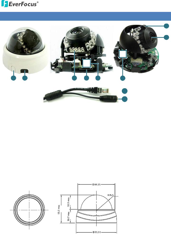
2. Physical Description
1
2
8 |
7 |
6 |
5 |
4 |
3 |
|
|
|
|
9 |
|
|
|
||
|
|
|
10 |
|
|
|
|
|
|
No. |
Item Name |
Descriptions |
||
1 |
Light Sensor |
Detects lights. |
||
|
|
|
|
|
2 |
Lens |
Fixed IRIS with 4 mm focal length and F2.0 aperture. |
||
|
|
|
|
|
3 |
Microphone |
One built-in microphone. |
||
|
|
|
|
|
4 |
Reset Button |
Resets all configurations to the factory default settings. |
||
|
|
|
|
|
5 |
Micro SD / SDHC Slot |
For inserting a micro SD / SDHC card. |
||
|
|
|
|
|
6 |
LEDs |
19 IR LEDs for infrared illumination in night vision applications. |
||
|
|
|
|
|
7 |
Release Button |
Push to remove the camera cover. |
||
|
|
|
|
|
8 |
Plastic Cut |
Remove to wire the cables along the wall / ceiling. |
||
|
|
|
|
|
9 |
LAN / PoE Cable |
Connects to a 10/100 Ethernet or PoE. |
||
|
|
|
|
|
10 |
Power Cable |
Connects to a 12 VDC power. |
||
|
|
|
|
|
Dimensions
2

EDN2160/2260/2560
3.Features
1/4” color CMOS image sensor delivers 1-megapixel resolution (EDN2160) 1/2.7” color CMOS image sensor delivers 2-megapixel resolution (EDN2260) 1/3” color CMOS image sensor delivers 5-megapixel resolution (EDN2560)
Mini palm-sized, easy installation
Provides True Day/Night functionality with automatic IR filter operation
Wide Dynamic Range function
Extended IR range of up to 10 meters with 19 IR LEDs
Dual streaming from H.264, MJPEG or MPEG4
H.264 up to 30 fps at 1280 x 800 of video resolution (EDN2160) H.264 up to 30 fps at 1920 x 1080 of video resolution (EDN2260)
H.264 up to 10 fps at 2560 x 1920 of video resolution; 30 fps at all the other resolution (EDN2560)
Built-in microphone
Built-in Micro SD Card slot for edge recording
Support Motion Detection and Email Notification functions
12 VDC / PoE
Multi-languages on Web interface
ONVIF / PSIA compliant
Supports EverFocus CMS and Mobile Applications (iOS / Android)
3
EDN2160/2260/2560
4.Installation
4.1 Packing List
Please check that there is no missing item in the package before installing.
• |
Camera x 1 |
• Mounting Kit x 1 |
• Base Plate and Mounting Plate x 1 |
- Screw Anchor x 2 |
|
• RJ-45 connector x 1 |
- Long Screw x 2 |
|
• Software CD x 1 |
- Short Screw x 2 |
|
• |
Quick Installation Guide x 1 |
- Fix Screw x 1 |
Note:
1.Equipment configurations and supplied accessories vary by country. Please consult your local EverFocus office or agents for more information. Please also keep the shipping carton for possible future use.
2.Contact the shipper if any items appear to have been damaged in the shipping process.
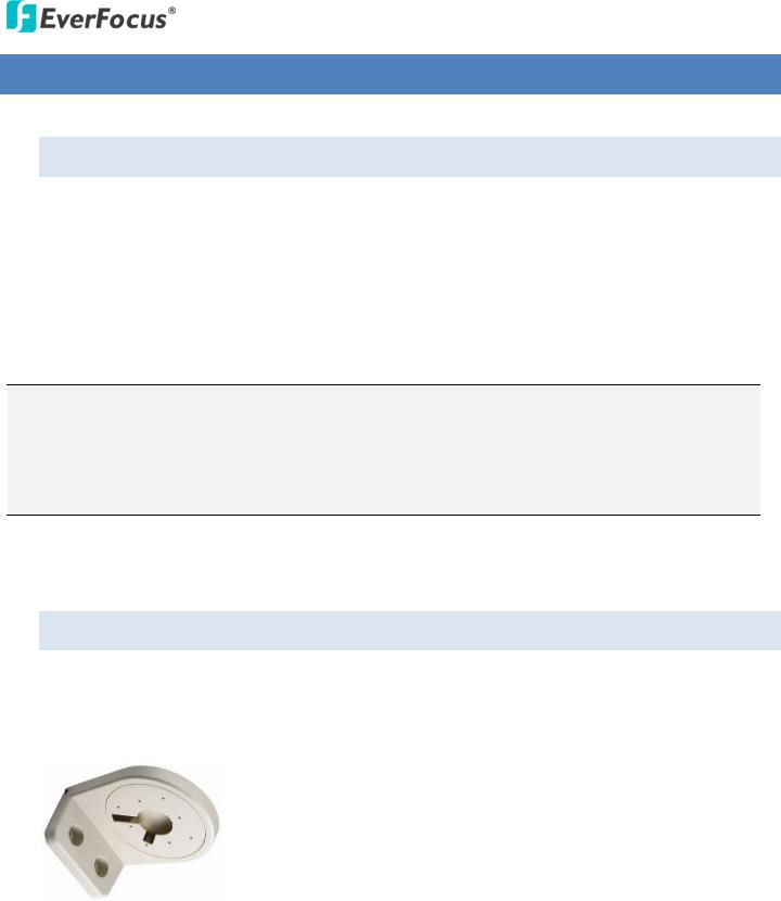
4.2 Optional Accessory
The Dome Bracket (BA-ED) is an L-type bracket designed to install the dome camera on the wall. For details on the wall-mount installation, please refer to 4.4 Wall-Mount Installation Using a Dome Bracket.
4
EDN2160/2260/2560
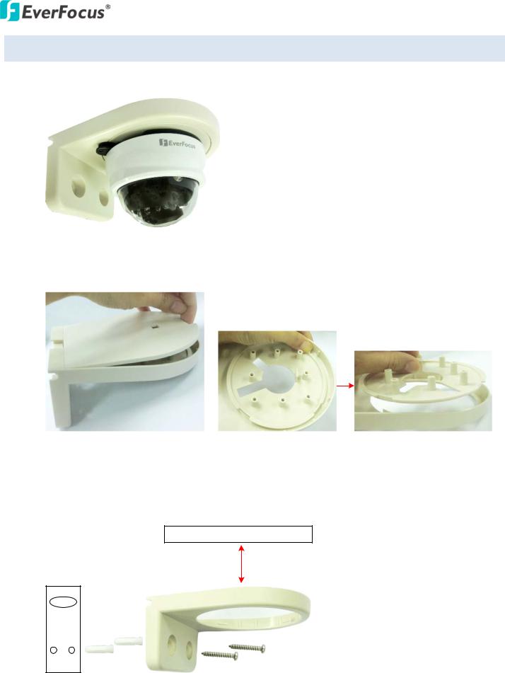
4.3 Basic Installation
The camera adopts a clever mounting design for users to easily install or remove it from the wall / ceiling.
Base Plate
 Mounting Plate
Base Plate |
Mounting Plate |
Please follow the detail steps below to mount the camera to the wall / ceiling:
1. Screw the Base Plate onto the bottom of the camera using the supplied Short Screws.
Base Plate
 Camera Base
2.Attach the Mounting Plate to the wall / ceiling and mark the location of the screw holes based on the Mounting Plate.
Mounting Plate
Make marks
Note: Before drilling the holes, make sure the camera lens can be adjusted to the desired view of your surveillance environment.
5

EDN2160/2260/2560
3.Drill the two marks and insert the supplied two Screw Anchors into the anchor holes. Then, screw the Mounting Plate to the wall / ceiling.
Mounting Plate |
Wall / Ceiling |
|
|
|
|
|
|
|
Screw Anchors
Long Screws
4.Thread the cables from the side cut of the camera or through the wall. a. To thread the cables through the wall / ceiling:
(1)Drill a hole on the upper-left side of the Mounting Plate.
Mounting Plate
Drill a Hole
(2) Run the cables through the hole and then slide the camera into the Mounting Plate.
Wall /
Ceiling
Cables
6
EDN2160/2260/2560
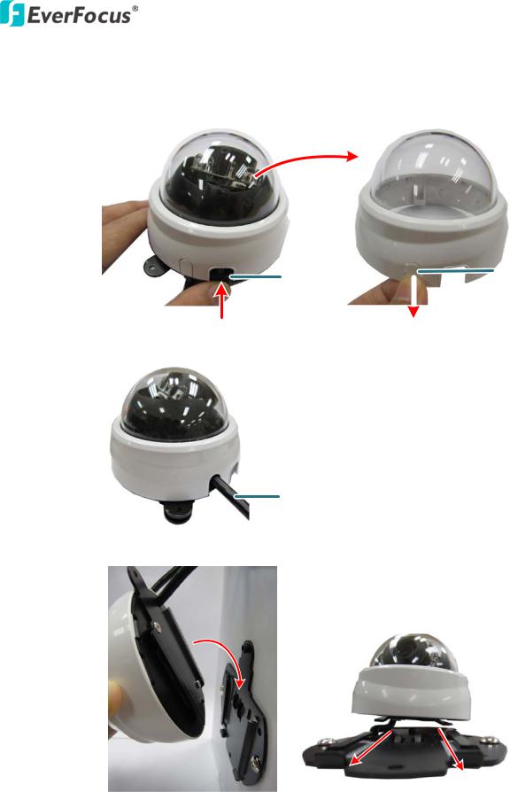
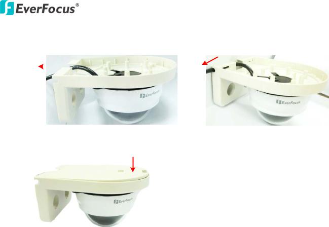
b.To thread the cables from the side cut of the camera:
(1)Remove the camera cover by pressing the Release Button. Break the Plastic Cut and then pull it out.
Release Button |
Plastic Cut |
|
|
|
|
(2) Run the cable through the side cut of the camera cover.
Cables
(3) Slide the camera into the Mounting Plate.
7
EDN2160/2260/2560
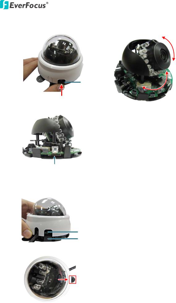
5.Press the Release Button to remove the cover and then: a. Adjust the camera Pan / Tilt angles.
Tilt: 70°
Release Button
Pan: 200°
b. Optionally insert a micro SD / SDHC card to the card slot.
Micro SD / SDHC Card Slot
6.Connect the network and power cables to the camera.
7.Place the dome cover back by aligning the Cut-Out with the Release Button. Press the dome cover for it to snap into place. A “click” sound should be heard when installed properly.
Cut-Out
Release Button
8. Screw the camera to the Mounting Plate using the supplied Fix Screw.
8
EDN2160/2260/2560
4.4 Wall-Mount Installation Using a Dome Bracket
You can optionally install the camera onto the wall using a Dome Bracket (BA-ED).
1.Remove the Top Cover and Bracket Plate from the Dome Bracket.
Top Cover
Bracket Plate
2.Drill two small holes on the wall and insert the supplied two Anchors into the holes. Drill another hole on the wall only if you wish to run the cables through the wall. Attach and screw the Dome Bracket to the wall using the supplied two Long Screws. Note that the distance between the ceiling and the Dome Bracket should be more than 10 cm.
Ceiling
> 10 cm
Hole
Wall
9

EDN2160/2260/2560
3.Screw the Base Plate onto the bottom of the camera.
Base Plate
4.Run the cable through the hole of the Bracket Plate and then screw the Mounting Plate to the Bracket Plate using the supplied three Short Screws.
Bracket Plate
Mounting Plate
5.Slide the camera into the Mounting Plate and then screw the camera using the supplied Fix Screw.
Fix Screw
6.Place the camera into the Dome Bracket.
10
EDN2160/2260/2560
7.Thread the cables from the side cut or through the hole on the wall.
Through the wall |
Along the wall |
|
|
|
|
8.Put the Top Cover back to the Dome Bracket.
11
EDN2160/2260/2560
5. Accessing the User Interface
This section explains how to access the Web interface of the camera for configuration.
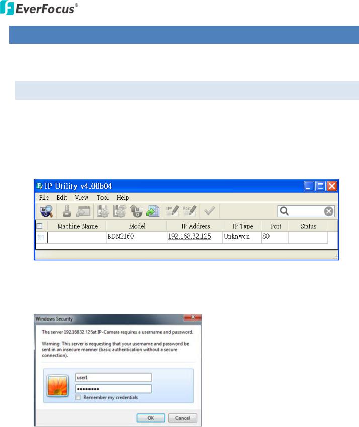
5.1 Checking the Dynamic IP Address
You can look up the IP address and access the Web interface of the camera using the IP Utility (IPU) software included in the software CD. Please connect the IP camera in the same LAN of your computer.
1.Install and then start the IPU program  , the following IPU window appears. The IPU will automatically search the IP devices connected in the LAN.
2.Double click the IP address of the desired device, the login window pops up. Type the user ID and password to log in. By default, the user ID is user1 or admin and the password is 11111111.
12
EDN2160/2260/2560
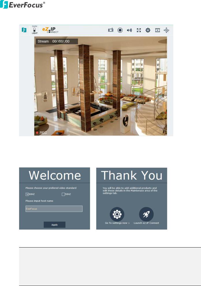
3.Click OK, the Live View window appears.
Note that for the first time user, you will be prompted to choose a desired video standard (lower-left image). Check the desired video standard, input a host name and then click the Apply button, a Thank You window appears (lower-right image). To access camera live view, click the Launch eZ.IP Connect button. To change video standard, see 7.2.1.1 Camera Setting.
Note:
1.You might be required to download ActiveX for viewing the camera feed. If asked, click Yes.
2.To enable Remote Live View, Firmware Upgrade and ActiveX Prompt on Internet Explorer, some settings have to be complete. Please refer to 5.2 Settings for Microsoft Internet Explorer in the User’s Manual.
13

EDN2160/2260/2560
4.To optionally configure the Machine Name, IP Address, IP Type or Port Number using IPU:
a.Log in the camera by checking the desired model and then click the Log in  icon. The Log in dialog box appears.
b.Click the OK button directly, the status of the selected camera will displayed Login.
Note:
9.The default user ID is user1 or admin and the default password is 11111111.
10.If you select more than one camera that has the same user ID / password, you will be able to log in several cameras at once.
c.Right click the column to configure the settings. Click the Apply Changes  button to apply and save the settings.
Note: Most networks uses DHCP to assign IP address, if you are unsure of your network settings, please consult your network administrators for configuration details.
14
EDN2160/2260/2560
5.2Settings for Microsoft Internet Explorer
A. To enable Remove Live View, Firmware Upgrade and ActiveX Prompt on Internet Explorer, some settings have to be complete. Please follow the steps below:
1.On the computer, click Start > Control Panel > System and Security > Action Center (click Change User Account Control Settings), the User Account Control Settings window appears. Adjust the slide bar to Never Notify and then click OK. Restart your computer if requested.
2.Open the Internet Explore, click Tools > Internet Options > Security Tab > Custom Level, the
Security Settings windows appears.
15

EDN2160/2260/2560
3.In the Download unsigned ActiveX controls field, select Prompt. In the Include local directory path when uploading files to a server field, select Enable. Click OK.
4.In the Internet Options window, click the Advanced tab and then disable Enable memory protection to help mitigate online attacks. Click OK.
16
Loading...