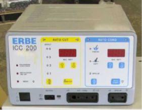
Erbe ICC 200 Service guideline

Title: Erbe ICC 200 ESU |
Date: 9-28-2017 |
|
By: Erbe, Tübingen & Georgia, USA |
DISCLAIMER: THIS PROCEDURE PROVIDED "AS IS" AND |
|
File = Erbe ICC 200.doc |
WITH POSSIBLE FAULTS. USER MUST VERIFY BEFORE USE. |
|
NEITHER PROVIDER NOR WEBSITE ASSUMES ANY |
||
|
||
|
RESPONSIBILITY FOR ITS USE. |
1.General
Applies to model ICC200. The following checks are likely considered minimal. Actual adjustments, if needed, are in the service manual noted below.
2.Reference Documents
Instruction manual P/N 80104-401 or 10128. Service manual P/N 80116-201
Note: A web search (include Bing) for these numbers preceded with “Erbe” often locates online copies.
3. Tools / Fixtures / Accessories |
|
|
Electrosurgical Analyzer: ex: Dempsey 443 or |
ICC 200 ESU |
|
better. |
||
|
||
Patient Plate Cable, Bipolar Cable/Forceps. |
|
|
Hand Control Pencil/Cable, Footswitch. |
|
|
Safety Tester |
|
4.Performance Verifications (Erbe recommends inspection on a yearly basis.)
4.1.Inspection
Check unit for any damage; i.e. connectors, knobs, the power cord and the footswitch with its cable and strain reliefs.
4.2.With no accessories plugged in, turn unit on.
After a brief self test, relevant visual displays will blink and the unit cannot be activated until any key on the front panel is briefly pressed. Verify that the up and down arrow power set buttons function. Change both settings from the original, and after turning power off then back on, verify
that the new settings re-appear.
Verify that the  button can change the CUT mode effects (i.e., various “Blends” ex: “1”, “2”, “3” and
“4” )
Verify that the  button can change the COAG mode effects (i.e., “Forced, “Soft” and “Bipolar”). Verify “Endo Cut” and “Auto Start”???
4.3.Neutral/Patient Plate/ Return Electrode (aka NESSY)
Note: To enable normal generator operation, the unit must see a resistance of 0–40 ohms between these two connector pins. Between 40 and 120, the unit will operate but with warning indications. Above 120, the unit cannot be activated.
Check with a variable test resistor connected between the connector pins. When the resistance exceeds 120 ohms, the “NESSY” LED will extinguish. Remove the neutral plug from its panel connector. A loud non-adjustable tone will activate, and the red patient plate lamp will light. To re-calibrate the ohm level, perform Test Program 16, Adjustment 9 in the service manual.
4.4.Power Measurement Setup
1
 Loading...