


 Loading...
ERBE
ERBOTOM ICC 350
Instruction manual 08.00
ERBOTOM ICC 350 V 4.X
10128-016, 10128-061, 10128-300, 10128-301, 10128-025,10128-402
ERBOTOM ICC 350 Z V 2.X
10128-065
ERBOTOM ICC 350 T V 2.X
10128-066
ERBOTOM ICC 350 M V 4.X
10128-080, 10128-083
ERBOTOM ICC 350 M-DOKU V 4.X
10128-081
Instruction manual 08.00

ISO 9001
EN 46001
All rights to this instruction manual, particularly the right to reproduction, distribution and translation, are reserved. No part of this instruction manual may be reproduced in any form (including photocopying, microfilm or other means), or processed, reproduced or distributed by means of electronic systems without prior written permission from ERBE ELEKTROMEDIZIN GmbH.
The information contained in this instruction manual may be revised or extended without prior notice and represents no obligation on the part of ERBE ELEKTROMEDIZIN GmbH.
©ERBE ELEKTROMEDIZIN GmbH, Tübingen 2000
Printed by: ERBE ELEKTROMEDIZIN, Tübingen |
Instruction manual No. 80104-301 |
Chapter |
Title |
Page |
1 |
INTRODUCTION ................................................................ |
1-1 |
1.1 |
Intended purpose of the ICC 350 ................................................ |
1-1 |
1.2 |
How do I work with this instruction manual? ............................. |
1-1 |
1.3 |
Explanation of the safety instructions ......................................... |
1-1 |
2 |
INITIAL OPERATION ........................................................ |
2-1 |
3 |
RISKS AND SAFETY |
|
|
OF HIGH-FREQUENCY SURGERY .................................. |
3-1 |
3.1 |
Unintentional thermal tissue damage .......................................... |
3-1 |
3.1.1 |
- due to HF leakage currents ....................................................... |
3-1 |
3.1.2 |
- due to unintentional activation of an HF generator ................... |
3-2 |
3.1.3 |
- due to inappropriate application ................................................ |
3-3 |
3.1.4- due to inappropriate or nonapplication of
|
the neutral electrode .................................................................... |
3-3 |
3.1.5 |
- due to unsuitable and/or faulty accessories ............................... |
3-4 |
3.1.6 |
- due to inattentiveness ................................................................ |
3-5 |
3.1.7 |
- due to an output error ................................................................ |
3-5 |
3.1.8- due to the ignition of flammable liquids, gases
|
and/or vapors ............................................................................... |
3-5 |
3.1.9 |
Unintentional burns due to hot electrodes ................................... |
3-6 |
3.2 |
Electric shock .............................................................................. |
3-6 |
3.3 |
Stimulation of nerves and muscles .............................................. |
3-6 |
3.4 |
Cardiac pacemaker ...................................................................... |
3-7 |
3.5 |
Danger of explosion .................................................................... |
3-7 |
3.6 |
Interference with other electronic equipment .............................. |
3-7 |
4 |
DESCRIPTION OF THE HIGH-FREQUENCY |
|
|
SURGICAL UNIT ............................................................... |
4-1 |
4.1 |
General description ..................................................................... |
4-1 |
4.2 |
Description of the controls .......................................................... |
4-4 |
1 |
Power switch .......................................................................................... |
4-4 |
2 |
AUTO CUT function field ..................................................................... |
4-5 |
3 |
AUTO COAG 1 function field ............................................................... |
4-6 |
4 |
AUTO COAG 2 function field ............................................................... |
4-7 |
5 |
AUTO BIPOLAR function field ............................................................ |
4-8 |
6 |
Working with programs ......................................................................... |
4-9 |
7 |
Connecting socket for neutral electrodes ............................................. |
4-12 |
8 |
Connecting socket for the AUTO CUT and AUTO COAG 1 |
|
|
function fields ...................................................................................... |
4-12 |
9 |
Connecting socket for the the AUTO CUT and AUTO COAG 2 |
|
|
function fields ...................................................................................... |
4-12 |
10 |
Connecting socket for the AUTO BIPOLAR function field ................ |
4-13 |
11 |
Safety field ........................................................................................... |
4-13 |
12 |
Connecting socket for a dual-pedal footswitch .................................... |
4-13 |
13 |
Connecting socket for a single-pedal footswitch ................................. |
4-13 |
14 |
Terminal for potential equalization ...................................................... |
4-14 |
15 |
Volume for acoustic signals ................................................................. |
4-14 |
16 |
Loudspeaker for acoustic signals ......................................................... |
4-14 |
17 |
Power connection ................................................................................. |
4-14 |
18 |
Power fuses .......................................................................................... |
4-14 |
4.3 |
Description of the safety features .............................................. |
4-14 |
5 |
ERBOTOM ICC 350 Z ....................................................... |
5-1 |
6 |
ERBOTOM ICC 350 T ....................................................... |
6-1 |
7 |
ERBOTOM ICC 350 M ....................................................... |
7-1 |
8 |
ERBOTOM ICC 350 M-DOKU ........................................... |
8-1 |
9 |
TECHNICAL DATA, SIGNALS, DIAGRAMS ..................... |
9-1 |
9.1 |
Technical data .............................................................................. |
9-1 |
9.2 |
Visual and acoustic signals .......................................................... |
9-5 |
9.3 |
Diagrams ..................................................................................... |
9-6 |
10 |
INSTALLATION ............................................................... |
10-1 |
11 |
CLEANING AND DISINFECTION OF THE UNIT ............ |
11-1 |
12 |
PERFORMANCE CHECKS ............................................. |
12-1 |
12.1 |
Automatic performance test after starting up the unit ............... |
12-1 |
12.2 |
Automatic performance check during activation ...................... |
12-1 |
12.3 |
Automatic error documentation ................................................. |
12-2 |
|
Error list ..................................................................................... |
12-3 |
13 |
SAFETY CHECKS ........................................................... |
13-1 |
14 |
MAINTENANCE, CARE, DISPOSAL .............................. |
14-1 |
15 |
GUARANTEE .................................................................. |
15-1 |
|
ADDRESSES |
|
1 INTRODUCTION
1.1Intended purpose of the ICC 350
The ICC 350 is a high-frequency surgical unit for cutting and coagulation. Due to its performance features, it has universal applications. To meet the special requirements of surgical specialty fields, the ICC 350 is available in several versions.
1.2How do I work with this instruction manual?
Please read the instruction manual for the ICC 350. It applies to all versions of this high-frequency surgical unit. If you have an ICC 350 Z, for example, please additionally read the chapter ICC 350 Z.
1.3Explanation of the safety instructions
The WARNING  safety instruction indicates a danger which can result in personal injury.
The CAUTION  safety instruction indicates a danger which can result in property damage.
The IMPORTANT safety instruction indicates a danger which can cause functional failure of the unit.
1-1
1-2
2 INITIAL OPERATION
Read carefully before initial operation of the unit.
In the development and production of this high-frequency surgical unit, the relevant, generally recognized rules of technology, as well as the valid occupational safety and accident prevention regulations have been taken into consideration. This ensures that patients, employees and third parties are protected from dangers to life and health during intended application of the highfrequency surgical unit, to the extent permitted by the type of application intended.
Initial operation
Before delivery, every high-frequency surgical unit is tested by the manufacturer in regard to its function and safety. To ensure that the unit also functions safely after shipping and installation at the operator’s site, the following points should be observed:
The operator should only operate the high-frequency surgical unit if the manufacturer or supplier
1.has subjected the unit to a performance test on site
2.has instructed the parties responsible for operation of the unit in handling of the unit by means of the instruction manual.
2-1
2-2
3 RISKS AND SAFETY OF HIGH-FREQUENCY SURGERY
3.1Unintentional thermal tissue damage
High-frequency surgery is associated in principle with various risks for the patient, the personnel and surroundings. In order to avoid these risks in practice, the surgeon and his/her assistants must recognize these risks and observe the appropriate rules for prevention of damage. In the following, these risks and rules for prevention of damage are explained.
3.1.1 Unintentional thermal tissue damage due to HF leakage currents
During high-frequency surgery, the patient unavoidably conducts high-frequency electrical current to ground potential. If the patient makes contact with electrically conductive objects during high-frequency surgery, a high-frequency electrical current can result at the contact point between the patient and this object, which can in turn cause thermal necroses. Not just objects made of metal are electrically conductive objects, but also wet cloths.
WARNING 
The patient must be insulated against electrically conductive objects during high-frequency surgery. The black elastic table covers on operating tables demonstrate a certain electrical conductivity for diverting electrical charges. Therefore they are never suitable for ensuring the required insulation of the patient against metal parts of the operating table. For this reason, an electrically insulating intermediate layer, for example dry cover cloths, must be laid between the patient and this black operating table cover during the application of high-frequency surgery.
Electrically insulated |
Grounded |
surface |
operating |
|
table |
Fig.: Insulated positioning of the patient on the operating table
If it is possible for this intermediate layer to become wet during the operation, for example due to perspiration, irrigation liquid, urine etc., wetting of these intermediate layers must be prevented by a watertight sheet of plastic. Urine should be carried away via catheter.
Extremities lying against the trunk or skin-to-skin contact points should be insulated from one another by laying dry cover cloths between them.
Do not apply ECG electrodes closer than 15 cm next to the operating field.
Needle electrodes or injection cannulae should not be used as ECG electrodes during high-frequency surgery.
3-1

3.1.2 Unintentional activation of an HF generator
Unintentional activation of an HF generator can lead to burns on the patient if the active electrode hereby touches the patient directly or indirectly through electrically conductive objects or wet cloths.
Unintentional activation of an HF generator can, for example, be caused by:
Unintentionally pressing a footswitch pedal
Unintentionally pressing a fingerswitch
Defective fingerswitches, footswitches or cables
Penetration of electrically conductive liquids (blood, amniotic fluid, urine, physiological saline solution, irrigation fluids etc.) into fingerswitches or footswitches.
Errors within the high-frequency surgical unit
WARNING 
To prevent burns on the patient due to unintentional activation of a high-frequency generator, the following application rules should be heeded:
Never lay active electrodes onto or beside a patient in such a way that they can touch the patient directly or indirectly through electrically conductive objects or wet cloths.
The lines to the active electrodes should be positioned in such a way that they touch neither the patient nor other lines.
Always set the acoustic signal, which indicates the active status of the high-frequency generator, so that it can be easily heard.
For operations in which the cutting or coagulation electrode unavoidably remains in contact with the patient even in a nonactive condition, e.g. for endoscopic operations, particular care is required. If such an electrode is unintentionally activated due to an error, this activated electrode should then not be removed from the body without special supervision. When removing the activated electrode from the patient’s body, burns can result on all areas within the body which come into contact with the activated electrode. For this reason, in case such errors occur, the power switch for the high-frequency surgical unit should be switched off immediately before an attempt is made to remove the activated electrode from the body.
3-2
3.1.3 Unintentional thermal tissue damage due to inappropriate application
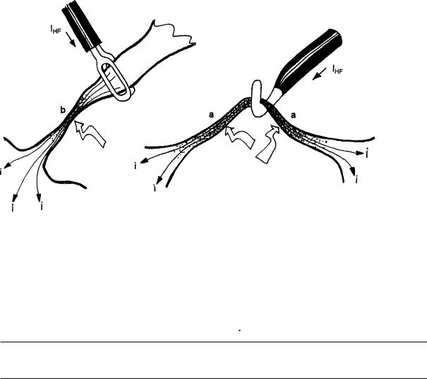
Generally speaking, the bipolar coagulation technique should be applied in preference to the monopolar coagulation technique. This particularly applies to coagulations on straight organs, on which the high-frequency current flows over longer areas through diameters which are approximately equal or become even smaller.
Fig.: Thermal damage of lateral tissue
The tissue is always first heated at places on the tissue where the diameter is smallest. If the HF current flows through the same diameter (a) over longer distances, the tissue coagulates over this entire distance. If the diameter of the tissue next to the application point of the coagulation electrode is smaller than at the point of application, coagulation will also occur next to the application point (b).
WARNING 
Always make certain that the HF current does not flow through thin tissue structures or vessels with a small diameter.
3.1.4Unintentional thermal tissue damage due to inappropriate or nonapplication of the neutral electrode
With inappropriate or even nonapplication of the neutral electrode, there is a large risk of unintentional thermal tissue damage both at the application point of the neutral electrode as well as to other areas on the patient’s body.
The neutral electrode must be applied with its entire surface as closely and reliably as possible to the operating field on the patient’s body.
3-3
WARNING 
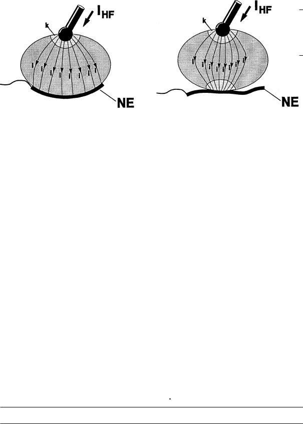
The effective contact surface, i.e. the electrical conductive value between the neutral electrode and the patient must correspond to the HF capacity used, meaning the intensity of the HF current. Here the effective contact surface means the surface of the neutral electrode which has electrically conductive contact to the skin of the patient during high-frequency surgery.
a) |
b) |
Fig.: The neutral electrode must be applied at an appropriate location on the patient’s skin using the entire contact surface available (a). If the neutral electrode has only partial contact to the patient’s skin (b), there is a risk that burning will occur at this location
3.1.5Unintentional thermal tissue damage due to unsuitable and/or faulty accessories
It must be ensured that only accessories in perfect condition are used for high-frequency surgery. Only accessories that are compatible or tested by the unit manufacturer must be used. This applies both to the active electrodes including cable and plugs, as well as to the neutral electrodes including cables and plugs.
When using an instrument with electric insulation, it is necessary to be certain that these insulations are not overloaded and destroyed by overly high electric voltages. The electric output voltages for the high-frequency surgical unit are indicated for the various cutting and coagulation modes relative to the possible settings in this instruction manual. The electric strength of the instrument insulation can be found in the technical data for the instruments or, in case of doubt, can be requested from the manufacturer of the respective instrument.
WARNING 
All insulation on electrodes, electrode holders, cables, plugs etc. must be in perfect condition.
3-4

3.1.6 Unintentional thermal tissue damage due to inattentiveness
Like a scalpel, high-frequency surgery is always a potential source of danger if handled without care.
WARNING 
The cutting or coagulation electrodes should always be handled with care and laid aside in the intervals between use so that neither the patient nor other persons can come in contact with the electrodes.
Laying unused electrode handles or coagulation forceps on the patient, next to the patient or within folds on the cover cloths is dangerous. Cases of burns on patients are known which were caused by laying the coagulation forceps within folds on the cover cloths which penetrated through the cloths into the patient’s skin and resulted in burns without being noticed.
3.1.7 Unintentional thermal tissue damage due to output error
The risk of unintentional thermal tissue damage is proportionate to the intensity and time limit set on the unit for cutting or coagulation.
WARNING 
The intensity for cutting or coagulation should only be set and only activated for as long as necessary for the intended purpose.
An insufficient effect at a standard setting can, for example, be caused by poor attachment of the neutral electrode, poor contact in the connectors, defective cables or electrically insulating tissue remnants on the active electrode. This must be checked before setting at a higher power.
3.1.8Unintentional thermal tissue damage due to the ignition of flammable liquids, gases and/or vapors
During high-frequency surgery, electric sparks or arcs that can ignite flammable liquids, gases or vapors occur at the active electrode.
3-5
WARNING 
Make certain during high-frequency surgical operations that anesthetics, skin cleaning agents and disinfectants are nonflammable. If their use is unavoidable, they must have completely evaporated and the vapor must be removed from the area of spark formation before switching on the high-frequency surgical unit.
Before application of high-frequency surgery in the gastro-intestinal tract, it must be ensured that no flammable (endogenous) gases are present here. There is danger of explosion if flammable gases are present. For this reason, these gases must be extracted and/or eliminated by flushing out the affected lumen with CO2before using high-frequency surgery.
During transurethral resection (TUR), H2O molecules may dissociate into H2 and O2 in the arc between the resection loop and the irrigation liquid. These gases may collect on the roof of the urinary bladder as a highly explosive gas mixture. If resection is performed in this gas mixture, dangerous explosions may occur.
3.1.9 Unintentional burns due to hot electrodes
Cutting and/or coagulation electrodes become hot during cutting and/or coagulation procedures indirectly through the heated tissue and through the electric arc.
WARNING 
Tissue can be unintentionally burnt immediately after cutting and/or coagulation procedures if electrodes that are still hot touch the tissue. Attention must be especially paid to this during endoscopic operations, such as during pelviscopic fallopian tube coagulation or during endoscopic polypectomy.
3.2Electric shock
An electric shock may occur if the high-frequency surgical unit delivers a too heavy low-frequency current or if a too heavy low-frequency current flows through the patient into the high-frequency surgical unit from another voltage source.
3.3Stimulation of nerves and muscles
A known risk of high-frequency surgery is the unintentional electric stimulation of the patient’s nerves and muscles. This stimulation can result from low-frequency electrical currents that are caused either by low-frequency current sources or due to electrical arcs between an active electrode and the patient’s tissue.
Electric alternating current with a frequency above 300 kHz is unable to stimulate nerves and muscles.
3-6

During cutting procedures, forced coagulation and spray coagulation, the unavoidable electric arcs between an active electrode and the tissue nevertheless have the effect that a portion of the high-frequency alternating current is rectified, from which more or less strongly modulated, low-frequency current components result which stimulate electrically stimulable structures such as nerves and muscles.
This can result in more or less strong spasms or muscle contractions.
WARNING 
When using high-frequency surgery on electrically stimulable structures, contractions of the affected muscles must be taken into account. This can occur, for example, during endoscopic operations in the urinary bladder in the vicinity of the obturator nerve and during operations in the area of the facial nerve.
3.4Cardiac pacemaker
For patients with implanted cardiac pacemakers or pacemaker electrodes, irreparable damage to the pacemaker and disturbance of the pacemaker function, which can lead to ventricular fibrilation, must be reckoned with.
3.5Danger of explosion
High-frequency surgical units always generate sparks during operation on the active electrode. For this reason, it is necessary to make certain during interventions that anesthetics, degreasers and disinfectants are neither flammable nor explosive. They should at least have evaporated completely before switching on the high-frequency surgical unit and be removed from the area of spark formation.
3.6Interference with other electronic equipment
High-frequency surgical units normally generate high-frequency electrical voltages and currents which can interfere with other electronic equipment.
When installing or arranging sensitive electronic equipment in the operating room, this problem should be taken into consideration. In principle, sensitive electronic equipment should be set up as far as possible from the high-frequency surgical unit and particularly from the cables providing HF current. In addition, the cables providing HF current, which act like broadcast antennas, should not be unnecessarily long and should never be positioned parallel or too close to cables from sensitive electronic equipment.
The unit has been fitted with a special generator in consideration of the disturbance of sensitive electronic equipment, which generates a relatively low interference level as compared to conventional high-frequency surgical units.
3-7
3-8

Standard
International |
7 |
8 |
9 |
10 |
4 DESCRIPTION OF THE HIGH-FREQUENCY SURGICAL UNIT
4.1General description
Cutting with automatic control of the HF voltage (Auto Cut)
The ERBOTOM ICC is equipped with automatic open and closed loop control systems which control and regulate the parameters relevant to the cutting quality so that each respectively selected cutting quality is guaranteed to be reproducible and constant.
Adjustable power limitation in the cutting mode
Since the ICC units are equipped with automatic control of the HF voltage in the cutting mode, a power setting in regard to cutting quality is not required. The adjustable power limitation is primarily intended to guarantee the safety of the patient from unintentional thermal tissue damage, and to protect fine cutting instruments, such as fine needle electrodes, from destruction due to overly high HF currents if these come in contact in activated condition with other metallic instruments. The latter, for example, is a risk during laparoscopic operations. This adjustable power limitation must not be confused with the power setting for conventional high-frequency surgical units, where the cutting quality is directly dependent upon the power setting.
Monopolar and bipolar cutting modes
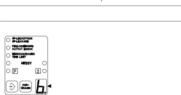
With the ERBOTOM ICC 350, both monopolar and bipolar cutting electrodes can be operated. A special operating mode is available for the users of bipolar cutting electrodes, which can be called up as program “b“.
Cutting with automatic control of the electric arc (HIGH CUT)
HIGH CUT is especially suitable for cutting in tissue with poor electric conduction. Since the HF voltage in the HIGH CUT mode can attain high values on the active electrode, HIGH CUT should however only be used with electrically well insulated instruments when cutting in tissue with poor electric conduction. For bipolar or quasibipolar cutting, HIGH CUT is not recommended inasmuch as the insulation paths for bipolar and quasibipolar instruments are generally very small and must not be exposed to higher voltages. For bipolar and quasibipolar instruments, automatic voltage control is recommended.
PPS (Power Peak System)
The initial incision phase can represent a special problem during an incision, particularly if the cutting electrode is firmly pressed against the tissue to be cut before activating the HF generator, so that the cutting electrode has a relatively large-surface, and therefore low-resistance, contact. This is the case, for example, for TUR and for endoscopic polypectomy. In such cases, the HF generator must provide higher-than-normal power so that the initial incision can proceed without delay, for otherwise a very large coagulation necrosis may result at the cutting location. The ICC is equipped with an automatic power control which recognizes low-resistance loads and controls the HF generator in such a way that it briefly provides enough power so that the HF voltage, i.e. the intensity of the electric arc, required for the set cutting quality is ensured even for a lowresistance load. Thanks to this device, the average power can be limited to relatively small quantities, which corresponds to an improvement in protection from unintentional thermal tissue damage.
4-1
ENDO CUT
A further special problem during endoscopic operations, for example during polypectomy and papillotomy, consists in the fact that the electrodes used for cutting, for example polypectomy loops and papillotomes, must be guided on long wire pulls through narrow working channels on flexible endoscopes, and therefore the operator has no direct control over the cutting procedure. However, particularly for polypectomy and papillotomy, a controlled incision is a requirement in preventing complications. An incision that is too fast can lead to bleeding of the cut edges due to lack of sufficient coagulation. An incision that is too slow can cause thermal damage, for example to the intestinal wall.
Soft coagulation
Soft coagulation can be activated by key or pedal. It is especially advantageous for use in combination with the Auto Stop mode available in the ICC. Here, the coagulation process is automatically stopped as soon as the electric resistance of the coagulum increases due to vapor formation. In this way, the coagulation process is prevented from stopping too early or too late. If the coagulation process stops too early, coagulation may be insufficient. If coagulation is too long, the coagulum can dry out and adhere to the coagulation electrode.
Forced coagulation
Forced coagulation is advantageous if an efficient hemostasis is to be achieved with relatively small-surface electrodes, such as TUR resection loops.
Spray coagulation
The Spray coagulation mode on the ICC is also suitable for Argon Gas coagulation.
Adjustable power limitation in the various coagulation modes
For the ERBOTOM ICC units, the surgically relevant coagulation qualities, i.e. the coagulation effects Soft Coag., Forced Coag. Spray Coag. and Bipolar Coag., are delimited by definition from one another and selectable by the press of a key. Nevertheless, the intensity of the different effects can be varied by power limitation.
The Soft, Forced and Spray modes are each doubly available
In this way, two different coagulation modes can be preset independent of one another and, if two coagulation instruments are used, applied independent of one another, although not simultaneously for reasons of safety. Thus for example one coagulation instrument can be connected and applied to Soft coagulation and another instrument to Argon Plasma coagulation on the same ICC 350.
Bipolar coagulation
In this coagulation mode, the HF voltage is, similar to Soft coagulation, automatically and constantly controlled, and its peak value always remains lower than 200 Vp, so that the current density and thus the coagulation effect is, for the most part, independent of the effective contact surface between the coagulation electrode and the tissue, provided the effective contact surface is not too large relative to the currently set power limitation.
The adjustable power limitation serves the purpose of protecting fine bipolar coagulation instruments, such as pointed bipolar coagulation forceps, from being thermally destroyed in case of a short between the two forcep tips.
4-2
The footswitch or Auto Start is used for activation.
In the Auto Start mode, the HF generator is automatically activated if both poles of the bipolar coagulation instruments used contact electrically conductive tissue simultaneously. Auto Start can occur either immediately at the moment of contact with the tissue or more or less temporally delayed. With immediate activation, it is possible to work very quickly, especially if several coagulations must be performed one after another. Delayed activation offers the operator the advantage that he/she can prepare and securely grasp the tissue to be coagulated with the bipolar coagulation forceps before the HF generator is automatically activated. Automatic activation of the HF generator only occurs if both poles of the bipolar coagulation instruments contact the tissue uninterruptedly for at least as long as the respectively selected delay lasts. If the contact is interrupted before the respectively selected period of delay is over, the respective period of delay restarts as of the next contact.
Deactivation can proceed either via the pedal (however only if it was also activated via the pedal), or via Auto Stop. In the Auto Stop mode, the HF generator is automatically deactivated as soon as the electric resistance of the coagulum increases due to vapor formation. In this way, the coagulation process is stopped for the coagulum dries out or even carbonizes. This prevents the coagulum from adhering to the coagulation electrode and that the coagulation electrode becomes soiled too quickly.
Programmability of the front panel
In spite of the multiple possibilities for use of the ICC 350, this unit is relatively simple and easy to operate. This especially applies to the utilization of the memory available in this unit, in which various front panel settings can be stored.
4-3

4.2Description of the controls
This symbol, in accordance with EN 60 601-1, is intended to indicate to the user that this unit must only be used on the patient if the user is acquainted with the operation and features of this unit.
The figures set in cursive relate to the ICC illustration for this chapter, or to the function fields in the text.
1Power switch
Using this power switch, the unit is switched on and off.
Each time after being switched on, the unit automatically proceeds with various performance checks. If an error in the unit or in the accessories is recognized here, a warning signal sounds and the determined error is indicated by a corresponding error number. (See Chapter 12.1, Automatic performance checks after switching on the unit). If no error is determined, the unit is ready to operate.
If the unit was switched off for less than approx. 15 seconds, all settings for the program used before switching off appear after the automatic performance check on the front panel, and the unit can be immediately reactivated. This is advantageous if, for example, the power supply briefly fails.
If the unit was switched off for longer than approx. 15 seconds, the basic setting of the program used before switching off appears after the automatic performance check on the front panel, whereby all relevant visual displays continue to blink and the unit cannot be activated until any key on the front panel is briefly pressed as confirmation that this program should be used. Then the relevant displays are continously illuminated and the unit can be activated using the available settings. These settings can be changed or adapted to the current requirements at any time. However, other programs can be selected as well.
2-5 Function fields
The AUTO CUT, AUTO COAG 1, AUTO COAG 2 and AUTO BIPOLAR function fields can be adjusted separately from one another, although not activated simultaneously for reasons of safety.
WARNING 
Function fields that are not used may be switched off completely to prevent unintentional activation. To do this the power limitation must be turned down so far in the corresponding function field until a beep is heard and “—“ appears on the digital display. The corresponding function field cannot be activated in this condition.
4-4
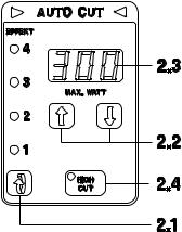
2 AUTO CUT function field
All parameters can be set in this function field that are relevant to cutting:
2.1Setting of the coagulation EFFECT when cutting
Here the required cutting quality in regard to the coagulation effect on the cutting edges can be adjusted.
Level 1 corresponds to minimum coagulation effect. Level 4 corresponds to maximum coagulation effect.
2.2Setting the power limitation
The HF power output can be limited in one watt steps from 300 watts to 1 watt. If display 2.3 shows “—“, the Auto Cut mode is switched off.
2.3Display of the set power limitation in watts
This display shows the respectively set power limitation
2.4HIGH CUT ON/OFF
The required Cut mode “AUTO CUT“ or “HIGH CUT“ can be set here. In “AUTO CUT“ mode, the HF voltage is constant. In the “HIGH CUT“ mode, the intensity of the arc between the active electrode and the tissue is constant.
Activation of monopolar cutting
can be done using either the yellow key on the electrode handle or the yellow pedal on the footswitch. Activation is visually signaled by continuous illumination of the triangle symbols in the upper part of the CUT function field and also acoustically signaled. Monopolar cutting instruments are connected to the CUT/COAG 1 and/or CUT/COAG 2 sockets.
Activation of bipolar cutting
proceeds via the yellow pedal. To do this, program “b“ = bipolar must be selected. Activation is visually signaled by continuous illumination of the triangle symbol in the upper part of the Auto Cut function field as well as acoustically signaled. Bipolar instruments are connected to the BIPOLAR socket. The maximum power setting for bipolar cutting is 100 watts. In program “b“, the AUTO BIPOLAR function field for bipolar coagulations can also be activated via the blue pedal of a dual-pedal footswitch or by the white pedal on a single-pedal footswitch. For bipolar cutting, the High Cut cutting mode is not required and therefore cannot be activated.
4-5
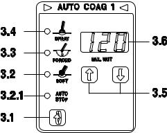
3 AUTO COAG 1 function field
All parameters can be set in this function field and are relevant to monopolar coagulation:
3.1Selection of the coagulation mode
By pressing this key, one of the following coagulation modes can be selected:
3.2Soft coagulation without Auto Stop
3.3Forced coagulation (Check the version. See Chapter 10.12)
3.4Spray coagulation (Also suitable for Argon Plasma coagulation)
3.5Power limitation
The HF power output can be limited in 1 watt steps from 120 watts to 1 watt. If the display 3.6 shows “—“, the Auto Coag 1 mode is switched off.
3.6Display of the set power limitation in max. watt
Activation
The coagulation modes for this AUTO COAG 1 function field can be started via the blue key on an electrode handle, and stopped via this key or automatically (Auto Stop). Activation is visually signaled by continuous illumination of the triangle symbols in the upper part of the AUTO COAG 1 function field as well as acoustically signaled.
4-6
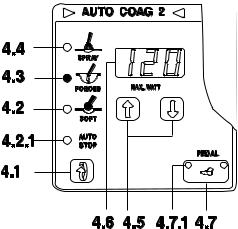
4 AUTO COAG 2 function field
All parameters can be set in this function field and are relevant to monopolar coagulation:
4.1Selection of the coagulation mode
By pressing this key, one of the following coagulation modes can be selected:
4.2Soft coagulation without Auto Stop
4.2.1 Soft coagulation with Auto Stop
4.3Forced coagulation (Check the version. See Chapter 10.12)
4.4Spray coagulation (Also suitable for Argon Gas coagulation)
4.5Power limitation
The HF power output can be limited in 1 watt steps from 120 watts to 1 watt. If the display 4.6 shows “—“, the Auto Coag 2 mode is switched off.
4.6Display of the set power limitation in max. watt
4.7Changeover switch for the blue pedal
If the left signal 4.7.1 is illuminated in this key, the currently selected coagulation mode of the Auto Coag 2 function field can be activated via the blue pedal of a dual-pedal footswitch.
Activation
The coagulation modes for this AUTO COAG 2 function field can be activated via the blue key on an electrode handle or via the blue pedal of a footswitch and stopped via this key or this pedal or automatically (Auto Stop). Activation is visually signaled by continuous illumination of the triangle symbols in the upper part of the COAGULATION function field as well as acoustically signaled.
4-7
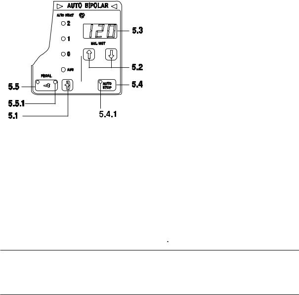
5 AUTO BIPOLAR function field
All parameters can be set in this function field and are relevant to bipolar coagulation:
5.1Selection of the Auto Start mode
If the unit is to be activated by Auto Start, three different Start modes are available:
AUTO START 2 AUTO START 1 AUTO START 0 AUTO START OFF
Auto Start with a long start delay Auto Start with a short start delay Auto Start without a start delay No Auto Start
The operator can use the start delay, for example, to prepare or safely grasp the tissue to be coagulated with the coagulation forceps before starting.
WARNING 
Only use Auto Start if unintentional contact of tissue with the coagulation instrument can be safely avoided. For endoscopic interventions, such as laparoscopy, pelviscopy or thoracoscopy, Auto Start should not be used because unintentional contact of the coagulation instrument with tissue cannot be safely avoided here.
The AUTO START key has no function on the ICC 350 No. 10128-025!
n some countries the ICC units are supplied with the AUTO START function deactivated. This may also apply in your case. If you nevertheless wish to use the AUTO START function, please consult your local ERBE branch office. You will find the address on the last page of the Instruction Manual. Technical Service will activate the AUTO START function for you on request.
5.2Power limitation
With the Auto Start switched off, the HF power output can be limited in 1 watt steps from 120 watts to 1 watt. With Auto Start, the HF power output is limited to 50 W max. If the display 5.3 shows “ —“, the Auto Bipolar mode is switched off. The power limit is recommended, for example, for pointed bipolar coagulation forceps, because in this way thermal damage to the forceps points can be prevented if these directly contact each other.
5.3Display of the set power limitation in max. watt
4-8
5.4Auto Stop mode
In the Auto Stop mode, the HF generator is automatically switched off as soon as the water reaches the vapor phase in the coagulum. The Auto Stop mode is switched once signal lamp 5.4.1 is illuminated.
5.5Activation, changeover switch for the blue pedal of a dual-pedal footswitch
If the right signal 5.5.1 is illuminated in this key, the Auto Bipolar can be started via the blue pedal on a dual-pedal footswitch. Auto Bipolar can also be activated via the white pedal on a single-pedal footswitch or by Auto Start.
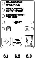
6 Working with programs
The ERBOTOM ICC 350 is equipped with 11 memory locations for storage of various basic settings. In this way, the settings required for every application of high-frequency surgery can be reduced to a minimum.
A basic setting is the setting which is defined at the factory or by the user and is stored in the program memory. Consequently, every program has a basic setting.
The basic setting for program “0“ is defined and programmed by the manufacturer and cannot be reprogrammed by the user. For the ERBOTOM ICC 350, Software Version 1.05 and up, the basic setting for program “0“ is defined and stored as follows:
AUTO CUT: Auto. voltage control, Effect 3, power limitation 150 watts
Activation with yellow key or yellow pedal
AUTO COAG 1: Soft coagulation, power limitation 60 watts
Activation with blue key
AUTO COAG 2: Forced coagulation, power limitation 60 watts
Activation with blue key or blue pedal
AUTO BIPOLAR: Power limitation 40 watts
Activation with white pedal, Auto Stop off
The basic settings for programs “1“ to “9“, as well as Program “b“ = Bipolar for bipolar cutting and coagulation, can be custom-defined and programmed by the user. It is recommended that the corresponding basic settings be documented.
The use of programs is especially practical for special application areas or cutom settings. The basic setting of each selected program is also immediately available again if the unit has been switched off in the meantime. If another program is required than that appearing in display 6.3 after the unit is switched on, the required program can be called up by pressing key 6.2 “PROGRAM“. The unit is immediately ready to operate using this program. If necessary, the functions and parameters appearing on the front panel for the appropriately selected program through the basic setting, can be changed or adapted to the immediate purpose and, if the changed
4-9
setting is also to be used for the following operations, it can be accepted into this program. To do this, only the SAVE key 6.1 must be depressed uninterruptedly long enough until “Set“ is indicated on display 3.6 for Auto Coag 1 and the signal heard continuously during storage changes into an intermittent signal.
WARNING 
The operator and/or user of the unit must ensure that programs are not changed and stored uncontrollably. Program changes must always be documented and all users must be informed.
Program b = Bipolar
With Program “b“, bipolar instruments connected to the bipolar output of the unit can be used for coagulation and cutting.
The parameters for bipolar cutting with a choice of coagulation effect are set via the AUTO CUT function field. The parameters for bipolar coagulation are set via the AUTO BIPOLAR function field.
Settings |
|
AUTO CUT |
The HF power output for bipolar cutting can be limited in 1 watt steps |
|
from 100 watts to 1 watt. |
|
EFFECT can be set from 1 to 4. |
AUTO COAG 1 |
This function field is not limited and all parameters can be set. |
AUTO COAG 2 |
This function field is switched off. |
AUTO BIPOLAR |
The HF power output for bipolar coagulation can be limited in 1 watt |
|
steps from 120 watts to 1 watt. |
|
With the changeover switch for the blue pedal of a dual-pedal |
|
footswitch, |
|
activation can be blocked using the blue footswitch pedal. |
|
Activation of AUTO STOP is possible. |
|
AUTO START is blocked in this program. |
4-10
Loading...