


 Loading...
APC 300
Service Manual
09.1998
V 2.xx
1

APC 300 No. 10132-010 Standard Version
ISO 9001
EN 46001
APC 300 No. 10132-011 UL Version
ISO 9001
EN 46001
Manual part number: 80116-121
for APC 300 International and UL Version
All rights reserved. No part of this document may be translated, stored in information retrieval systems, or transmitted in any form or by any means - electronic or mechanical, including photocopying, recording or otherwise - without the written permission of ERBE Elektromedizin.
Printed by: ERBE Elektromedizin
Printed in Germany
Copyright © ERBE Elektromedizin GmbH, Tübingen 1998
2
ERBE APC 300
Service Manual
3

4

5

System safety
Test functions
Status monitoring
Watchdog monitoring
SWSR monitoring
Exception processing
Stack monitoring
Flash memory
Check sum
Dose monitoring
Self check
Self check step 1
Self check step 2
Self check step 3
Self check step 4
Self check step 5
Display on activation
Reset operational data recording
Coded level
Maximum
instrument parameters
System setup
Adjust argon flow
Set flow
Display measurements
Store flow measurements
Instrument recognition
Instrument recognition
Instrument measurements
Store measurement
Activation recognition
Activation recognition
Activation measurements
Store measurements
Display memory page values
Display page values
Display elements 0-127
Init. error page
Init. system page
Init. application programs
Menu text in German
Menu text in English
Menu text in French
Menu text in Spanish
6
Contents
Chapter |
Title ........................................................................................ |
Page |
1 |
Safety notes for servicing ..................................................................... |
9 |
2 |
General Description of Clinical use .................................................... |
11 |
3 |
Installation ............................................................................................ |
13 |
4 |
Gas supply ............................................................................................ |
17 |
5 |
Description of the front and back panels .......................................... |
19 |
6 |
Technical Data ...................................................................................... |
23 |
7 |
Circuit descriptions ............................................................................. |
25 |
|
Circuit diagram of the APC 300 .............................................................. |
26 |
|
Circuit description of the APC 300 ......................................................... |
27 |
|
The main board ...................................................................................... |
28 |
|
The microcomputer unit ......................................................................... |
34 |
|
The pneumatic unit ................................................................................ |
39 |
|
The fluorescent display tube .................................................................. |
41 |
|
The switching power supply ................................................................... |
42 |
|
The APC keyboard ................................................................................. |
43 |
8 |
Test and adjustment instructions ....................................................... |
45 |
|
Measurement equipment and testing facilities ....................................... |
45 |
|
Tools for loading the program code ........................................................ |
45 |
|
Code level, identification numbers ..................................................... |
45 |
|
Adjustment of activation recognition ...................................................... |
46 |
|
Adjustment of argon flow ........................................................................ |
47 |
|
Test functions ......................................................................................... |
48 |
|
Checking for leaks ................................................................................. |
49 |
|
Testing footswitch signals to the surgical equipment ............................. |
50 |
|
Continuous test ...................................................................................... |
51 |
|
Memory page values, initialization ......................................................... |
51 |
|
Standard settings ................................................................................... |
52 |
|
Limiting parameters ............................................................................... |
53 |
|
Standard settings in rinse parameters program ..................................... |
54 |
7
9 |
Finding errors ....................................................................................... |
55 |
|
Finding errors in the APC 300 ................................................................ |
55 |
|
APC 300 appears to have broken down ................................................ |
57 |
|
No reaction from APC 300 ..................................................................... |
58 |
|
Device reacts but nothing visible on display .......................................... |
59 |
|
Error number and text are displayed ...................................................... |
60 |
|
Output error, deviations, irregularities .................................................... |
61 |
|
Operating error during switch-on phase ................................................. |
62 |
|
Self check error, hardware error, accessory error .................................. |
63 |
|
Check sum error, system error ............................................................... |
64 |
|
Service support through test programs .................................................. |
65 |
10 |
Finding errors when there is a leak in the argon gas unit ............... |
69 |
|
Notes on safety ...................................................................................... |
69 |
|
Gas leak in system ................................................................................. |
70 |
|
Gas leak in inlet section of the APC 300 ................................................ |
71 |
|
Gas leak in outlet section of the APC 300 .............................................. |
72 |
|
Gas leak in the high-pressure component of the system ....................... |
73 |
11 |
Exchange of components and assemblies ........................................ |
75 |
|
Line fuses ............................................................................................... |
76 |
|
Device outlet with power line filter .......................................................... |
77 |
|
Power switch .......................................................................................... |
78 |
|
Power control board ............................................................................... |
79 |
|
Footswitch outlet .................................................................................... |
80 |
|
Loudspeaker .......................................................................................... |
81 |
|
Gas connections of the rear panel ......................................................... |
82 |
|
Gas connections of the front panel ........................................................ |
83 |
|
Changing argon cylinder ........................................................................ |
84 |
12 |
List of components and assemblies mentioned in Chapter 11 ....... |
85 |
Please notice: All values in the displays are shown in [bar] or [mbar]. 1 bar = 14.5 psi.
8

1 Safety notes for servicing
WARNING |
The safety instruction WARNING denotes a danger which can cause injury |
|
to persons. |
CAUTION |
The safety instruction CAUTION denotes a danger which can cause damage |
|
to property. |
ATTENTION |
The safety instruction ATTENTION denotes a danger which can cause failure |
|
of the device. |
Safety precautions against the threat of electric shocks
WARNING! Only connect the APC 300 using the power cord supplied by ERBE, or one of at least the same quality, to a properly installed grounded outlet. If you use an equipment cart, this also applies to the power cord of the cart. The power cord must bear the national mark of conformity.
For safety reasons, multiple outlets and extension cords should not be used. If their use is unavoidable, they, too, must be provided with proper grounding.
WARNING! Unplug the power cord from the outlet before exchanging parts of the device or cleaning it.
WARNING! Do not plug in a mains cable which is wet into the device or into a outlet.
WARNING! Do not touch any unprotected wires or conductive surfaces while the device is disassembled and is under voltage. Never carry a grounding belt while working with a device under voltage.
WARNING! The unit is protected by mains fuses. If one of these fuses blows, the unit must not be used on patients until it has been checked by a properly trained technician. Only replacement fuses of the rating specified on the unit’s name plate may be used.
WARNING! High-frequency voltages of over 1000 V are needed to ionize argon. Check that there is no damage to the electrical insulation of the applicators and all cords prior to use.
Dangers when handling argon cylinders
WARNING! Gas cylinders may only be transported with valve protection (cylinder cap).
WARNING! Protect the argon cylinder from being warmed by heaters or open fires.
WARNING! Argon cylinders may only be connected to the APC 300 with the pressure reducer and hoses provided by ERBE!
WARNING! No force of any kind should be exerted on cylinders, cylinder connections or the pressure reducer. Secure the argon cylinder during transport, storage and use from tipping over or falling down by means of chains, straps, safety belts. Always use the safety belt on the mobile equipment cart.
WARNING! The input pressure at cylinder connections 1 and 2 of the APC 300 must not exceed 4.5 bar (65.25 psi). If the unit is connected to a central argon supply, the input pressure must not exceed 2.5 bar (36.25 psi).
9
WARNING! Damaged cylinders must not be used. Mark them. Inform the argon supplier immediately. Only use argon cylinders conforming to your national safety standards.
WARNING! The APC 300 may only be operated with argon. A cylinder containing a dangerous or improper gas could be connected to the cylinder connection of the unit. Check each cylinder to ensure that it really does contain argon. Identification must not be damaged or missing.
WARNING! Argon is heavier than air. If it builds up in the air being breathed, it can displace the oxygen, so that there is a danger of suffocation. Symptoms of oxygen deficiency are drowsiness, rising blood pressure and breathing difficulties. In an atmosphere of pure argon, sudden and unexpected loss of consciousness and suffocation occur.
A short hissing noise will be heard when the gas valves are opened due to the argon flowing into the hoses. If this hissing continues for longer than 2 seconds when a cylinder is opened, there is a leak and the argon cylinder must be closed again immediately. The unit may not be used until the leak has been repaired. Make sure that the hoses are tightly connected to the APC 300. The same applies to the pressure reducer connection to the argon cylinder. Close the safety valve of the argon cylinders after use.
Environment
ATTENTION: The APC 300 can be operated at a room temperature of between +10 and +40° C. The effective humidity can be between 30% and 75%, non-condensing. If these tolerances are exceeded in either direction, the unit may break down.
ATTENTION: If the APC 300 has been stored or transported at temperatures below +10 °C, especially below 0 °C, the unit requires about 3 hours to acclimatize at room temperature.
ATTENTION: The APC 300 must be set up in a way that permits air to freely circulate around the case. The unit must not be set up in narrow niches or shelves.
CAUTION! The APC 300 is protected against penetration by liquids according to EN 60-601-2-2. The case is not absolutely water tight. For this reason, do not set up the unit in the direct vicinity of tubes or vessels containing liquids.
Electrostatically sensitive components
CAUTION! This device contains electrostatically sensitive components. Work at an anti-static workplace while repairing the device. Wear a grounding armband while working with electrostatically sensitive components. Hold the circuit boards by their non-conducting corners. Use an anti-static container for transporting electrostatically sensitive components and the circuit boards.
10
2 General Description of Clinical use
APC equipment combines argon gas with a monopolar power source. The electrode in the argon channel of the applicator is connected to an electrosurgical generator.
The APC applicator ionizes the argon gas where it remains ionized approximately 2-10 mm distal to the tip of the applicator. lonized Argon gas is electrically conductive. This allows the current to flow between the applicator and the tissue. Current density upon arrival at the tissue surface causes coagulation. The application of the energy to the tissue is uniform, and contact free.
The Argon plasma beam acts not only in a straight line (axially) along the axis of the applicator, but also lateralIy, radially and "around the corner" as it seeks conductive bleeding surfaces. Following physical principles, the plasma beam has a tendency to turn away from already coagulated (high impedance) areas toward bleeding or still inadequately coagulated (low impedance) tissue in the areas receiving treatment. This automatically results in evenly applied, uniform surface coagulation.
11
12
3 Installation
First-time operation
The APC 300 has been checked for proper and safe operation prior to shipment. In order to guarantee that the unit functions safely after transport and installation by the operator, it may only be put in operation after:
1.It has been subjected to a functional check in conjunction with the electrosurgical unit at the location of operation, and
2.those responsible for operating this combination of equipment have been instructed by the manufacturer or supplier on the proper use of this combination of equipment with reference to the operating instructions.
Mains fuses
The unit is protected by mains fuses. If one of these fuses blows, the unit must not be used on patients until it has been checked by an experienced technician. Only use replacement fuses of the rating specified on the unit's name plate.
Installation on the equipment cart
APC 300
The APC 300 is normally installed on an ERBE-equipment cart Type 20185-008 International version, 20185-009 UL version. It also carries the argon gas cylinder(s) and the high-frequency surgical unit required for operation.
Electrosurgical unit
The electrosurgical units ERBOTOM ACC 450 and ICC 350 are equipped with a high-frequency leakage current monitor which samples for high-frequency leakage current in the grounding and potential equalization conductors in these units. For this reason the units must be installed on the APC 300 in such a way that their cases are not in electrical conducting contact with the APC 300 casing: i.e. the aforementioned electrosurgical units must be electrically insulated and installed on the surface provided on the APC 300.
Location of equipment cart in the operating theatre
If the electrosurgical unit and the APC 300 are installed together on an equipment cart, this system must be kept outside any operating theatre subject to danger of explosion. Read the operating instructions of the electrosurgical units under Explosion protection ◊.
13
Electrical Installation on the equipment cart
Only connect the APC 300 using the power cord supplied by ERBE, or one of at least the same quality, to the equipment cart's power connection. The power cord must bear the national mark of conformity. The power cord is connected to a properly installed grounded outlet.
Apart from the APC 300 and the electrosurgical unit, no other appliances must be connected to the mains outlets of the equipment cart.
For safety reasons, multiple outlets and extension cords should not be used. If their use is unavoidable, they, too, must be provided with proper protective grounding.
To avoid high frequency disturbance, and to protect the patient, connect the potential equalization pins of the electrosurgical unit and the APC 300 to the equipment cart via potential equalization conductors. Connect the potential equalization of the equipment cart to the potential equalization of the operating theatre.
NOTE
The CE 0124 sign is not at the
UL version.
 power cord from APC 300 to equipment cart
 power cord from ICC to equipment cart
 power cord of the equipment cart
 Potential equalization equipment cart - operating theatre
 Potential equalization equipment cart - ICC
 Potential equalization equipment cart - APC 300
14
Environmental conditions
The APC 300 can be operated at a room temperature of between 10 and 40 °C. The effective humidity can be between 30% and 75%, non-condensing. If these tolerances are exceeded in either way, the unit may break down.
The APC 300 must be set up in a way that permits air to freely circulate around the case. The unit must not be set up in narrow niches or shelves.
The APC 300 is protected against penetration by liquids according to EN 60-601-2-2 . The case is not absolutely watertight. For this reason, do not set up the unit in the direct vicinity of tubes or vessels containing liquids. Do not place any liquids on the APC 300.
15
16
4 Gas supply
Central gas supply
The maximum permissible input pressure is 2.5 bar (36.25 psi). The APC 300 must be modified by a technician if a central argon supply is used.
Connecting argon cylinders
The input pressure at cylinder connections 1 and 2 of the APC 300 may not exceed 4.5 bar (65.25 psi).
ERBE advises working with two argon cylinders with a volume of 5 liters and a pressure of 200 bar (2900 psi). The APC 300 has been programmed by ERBE to operate with this type of cylinder. If you wish to use other types of cylinders, you must reprogram the cylinder data in the menu Argon gas information under menu point Changing cylinder data.
To change cylinders, the APC 300 must be switched on.
Unmounting cylinder
1.Shut the cylinder valve. The cylinder valve may be a little stiff.
2.Remove the pressure hose of the argon cylinder at the rear of the APC 300.
3.Place the hose opening on the drainage pin at the rear of the APC 300 and press. The hose contains a residue of argon which escapes with a loud hissing noise.
4.The union nut of the pressure reducer should only be unscrewed to the left and removed by hand.
Mounting cylinder
1.The pressure reducer should only be screwed onto the new cylinder to the right by hand.
2.Open the cylinder valve.
3.Put the pressure hose onto the cylinder connection of the APC 300.
The system will now automatically be rinsed with argon by the APC 300. If the presure hose and pressure reducer are fitted tightly, no further hissing noises should be audible!
17

Cyllinder valve |
Union nut |
Connecting pressure reducer to cylinder
Drainage pin
Pressure hose
Connecting pressure hoses
NOTE
The CE 0124 sign is not on the UL version.
18

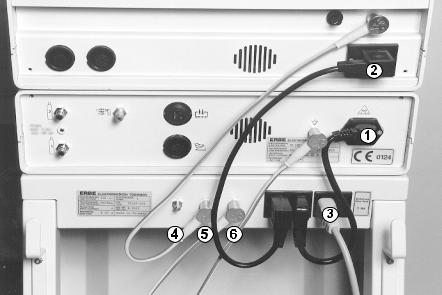
5 Description of the front and rear panels
Diagrams on folding leaf clockwise
Operating elements on the front panel
Display
On the display, the graphical interface (shell) of the APC 300 is shown. The shell is the interface between the operator and the unit's software. Using the shell, the instrument's COAG flow and CUT flow, as well as all the functions of the APC 300, can be controlled and the unit modified to suit your requirements. See CHAPTER 7
Description of the graphical interface of the APC 300 in APC 300 Handbook ◊.
UP / DOWN buttons
The UP / DOWN keys are used to set the flow parameters. For instance, up: increases COAG flow, down: decreases COAG flow.
In addition, the UP / DOWN keys are used for marking menu items in selection menus. All the APC 300's menus have the same structure. There is a cursor in the second line. If you press the up or down keys, the cursor runs up and down the menu items.
PROGRAM button
The APC 300 possesses 13 application programs. Using these, you can, among other things, program and store COAG flow and CUT flow settings for a particular instrument.
Using the program key, the selected application program is started.
ENTER button
The enter key is used to alternate between the standard display and the program selection menu and for calling the menu item marked. Its current function is always shown on the bottom, at the right of the display.
Start of the menu |
|
Cursor |
||||||||
|
|
|
|
|
|
|
|
|
|
|
|
|
|
|
|
|
|
|
|
|
|
|
|
|
|
|
|
|
|
|
|
|
|
|
|
|
|
|
|
|
|
|
|
|
|
|
|
|
|
|
|
|
|
|
|
|
|
|
|
|
|
|
|
|
|
|
|
|
|
|
|
|
|
|
|
|
|
|
|
|
|
|
|
|
|
|
|
|
|
|
|
|
|
|
|
|
|
|
|
|
|
|
|
|
|
|
|
|
|
|
|
|
|
|
|
|
|
|
|
|
|
|
|
|
|
|
|
|
|
|
|
|
|
|
|
|
|
|
|
|
|
|
|
|
|
|
|
|
|
|
|
|
|
|
|
|
|
|
|
|
|
|
|
|
|
|
|
|
|
|
|
|
|
|
|
|
|
|
|
|
|
|
|
|
|
|
|
|
|
|
|
|
|
|
|
|
|
|
|
|
|
|
|
|
|
|
|
|
|
|
|
|
|
|
|
|
|
|
|
|
|
|
|
|
|
|
|
|
|
|
|
|
|
|
|
|
|
|
|
|
|
End of the menu
19

PURGE button
Using the purge key, the rinse program is called. Before an instrument is actuated for the first time it must be rinsed with argon.
Instrument outlets
Argon outlet
Argon output. Insert the instrument's argon gas connection into this outlet.
Multiple outlet
Input of finger switch signals, instrument recognition, output of high-frequency current. Insert the instrument's multiple plug into this outlet.
Meaning of the symbol 


The unit has been built in compliance with Type CF (cardiac floating) and it has a patient leakage current of less than 10 µA. The APC 300 is protected against defibrillator voltages.
HF inputs
The high-frequency current of the electrosurgical unit is conducted to the APC 300 via this outlet. Insert the highfrequency lead into the outlet. Connect it to the CUT / COAG outlet of an ERBE electrosurgical unit. The ICC 300 and 350 possess two CUT /COAG outlets. Please refer to the CHAPTER 8 entitled Actuation concepts in APC 300 Handbook ◊ to discover which outlet is used for which concept.
Mains switch
Before the unit is switched on, the APC 300 should be installed and configured as described in CHAPTERS 4 and 8 ◊in APC 300 Handbook .
Switch on the APC 300 about 5 minutes before starting an application. The unit requires this amount of time to reach its thermal equilibrium and to conduct self checks and functional tests.
Self checks
After being switched on, the unit conducts a self check in which the pressure sensors are tested. If an error is identified, the message Selfcheck Error appears on the standard display. The unit of flow [L/min] is not shown. Despite this error, the COAG flow and CUT flow can still be set and the unit utilized.
If a self check error occurs, the APC 300 should only be used in an emergency when no reserve unit is available as an argon overdose could occur. This is, however, less of a threat than the non-availability of the APC 300 in an emergency.
Functional test
The unit conducts a functional test in which the keys on the front panel, the foot and the finger switches are checked. In addition, the APC 300 identifies whether a supply of argon gas is available. The supply level in the gas cylinders may also be identified. Errors are displayed in plain language and signalled by an audible signal.
Meaning of the symbol 
Only use the APC 300 if you are familiar with its operation and properties.
20
Operating elements on the rear panel
Argon cylinder connections
Only argon gas cylinders or a central argon supply may be connected to these cylinder connections.
Cylinders with a capacity of 5 liters or other volumes can be connected. The pressure reducer supplied by ERBE must be installed on the argon cylinders. The cylinders may only be connected using the pressure hoses supplied by ERBE. The input pressure for the gas cylinders is maximally 4.5 bar (65.25 psi).
If the APC 300 is connected to a central argon supply, the maximum input pressure is 2.5 bar (36.25 psi).
WARNING! The APC 300 may only be operated with argon. A cylinder containing a dangerous or improper gas could be connected to the cylinder connection of the unit. Check each cylinder to ensure that it really does contain argon. Identification must not be damaged or missing.
Argon cylinders may only be connected to the APC 300 with the pressure reducer and hoses provided by ERBE.
Please read the APC 300 Handbook CHAPTER 5 Changing cylinders ◊. Please read sections Danger of pressure explosions and Dangers associated with handling of argon in CHAPTER 2 Notes on safety ◊.
Drainage pin
There is a residual amount of argon in the pressure hoses of empty argon cylinders. In order to empty the hose when changing the cylinder, the hose is pressed onto the drainage pin.
Output for actuation signals
The actuation signals (foot or finger switch of the instrument) are conducted to the electrosurgical unit via this outlet. Insert the connection lead 20189-022 or 20132-063 into this outlet and connect it to one of the foot switch outlets at the rear of the electrosurgical unit. Please refer to CHAPTER 8 Actuation configurations ◊ in APC 300 Handbook to discover which outlet and which lead is used for which configuration.
Power cord
WARNING! Only connect the APC 300 using the power cord supplied by ERBE, or one of at least the same quality, to a properlyly installed grounded socket. The power cord must bear the national mark of conformity. If you use the equipment cart provided by ERBE, the power cord of the APC 300 is connected to the outlet of the cart.
For safety reasons, multiple outlets and extension cords should not be used. If their use is unavoidable, they, too, must be provided with proper protective grounding.
Please read the section Electrical installation on the equipment cart in the Handbook CHAPTER 3 entitled Installation ◊.
Potential equalization connections
To avoid high-frequency disturbance, and to protect the patient, connect the potential equalization pin of the APC 300 to the equipment cart via potential equalization conductors.
Loudspeaker
Over the loudspeaker of the APC 300, actuation and warning signals are emitted. Always place the APC 300 / the equipment cart in a position where the audible signals can be heard clearly.
21
Foot switch outlet
A singleor two-pedal foot switch can be connected to this socket. Please refer to CHAPTER 8 entitled Actuation configurations in APC 300 Handbook ◊ to discover which outlet is used for which concept.
Drainage opening
During the self check, argon is expelled through this opening.
22

6 Technical Data
Technical Data
APC 300 Typ Sp. No. 10132-010 Standard version
APC 300 Typ Sp. No. 10132-011 UL version
Supply voltage
Current input
Mains fuse
Protective Class according to
EN 60 601-1 IEC 601-1
Potential equalization
Cylinder connections
Input pressure of cylinder connections when gas cylinders are connected
Maximum input pressure of cylinder connections when central gas supply is connected
Maximum cylinder pressure
Minimum purity of argon
Maximum gas flow rate
Modes of actuation
Automatic instrument identification
Automatic flow setting
Plain language error messages
Weight of APC 300
Size of APC 300
Size of equipment trolley
100-230 V
50 / 60 Hz
0.3 A
T 1 A
I, CF
Yes
2 connections,
2 cylinders 5 l recommended
Minimum 2.5 bar (36.25 psi), maximum 4.5 bar (65.25 psi)
2.5 bar (36.25 psi)
200 bar (2900 psi)
99.998 %
from 0.1 l/min to 9 l/min regulated argon flow with pressure limitation
Foot switch or finger switch
Yes
Yes
Yes
6.8 kg
W x H x D 410 x 105 x 380 cm
W x H x D 161 x 41 x 150 inches
410 x 820 x 445 cm
161 x 213 x 175 inches
23
24
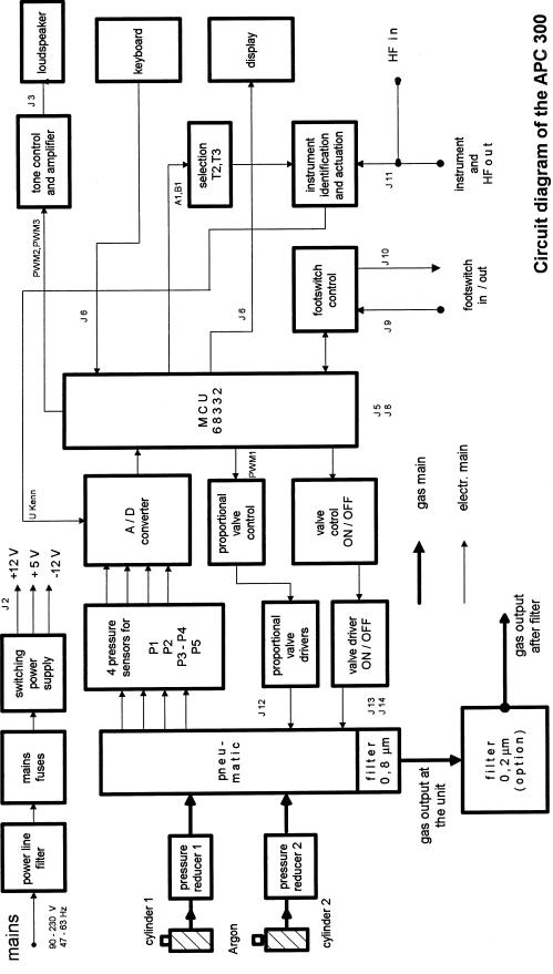
7 Circuit diagram, circuit descriptions
The circuit diagram of the APC 300
In conjunction with suitable electrosurgical equipment (e.g. from the ERBE ICC series), the Argon Plasma Coagulator APC 300 is an argon coagulator controlled and regulated by microcomputer.
The mains voltage in the range of 90V to 230V nominal arrives via a power line filter (to limit EMC problems) and the mains fuses at a switching power supply which adjusts the highest permissible power voltage range and produces and stabilizes the required operational voltages + 12 V, + 5 V and - 12 V.
The argon emerges from the supply cylinders via a separate pressure reducer to a pneumatic unit in which several electrically controlled valves are located for controlling and regulating the flow of the argon. In addition, a 0.8 µ filter is integrated to remove particles in the gas flow.
The valves of the pneumatic unit are set by the microcomputer unit (MCU 68332) both through the proportional valve driver and the valve controller and valve driver.
From the pneumatic unit, hose connections lead to four pressure sensors by means of which the gas flow is regulated and the proper function of the gas unit can be tested. The analog output signal of the pressure sensors is fed through an analog/digital converter to the microcomputer unit for evaluation.
A fluorescent display tube (display), a keyboard and a loudspeaker serve as interfaces for communication between the user and the APC 300.
The display receives its data from the microcomputer unit. Inputs to the keyboard are fed to the microcomputer unit and the audible signals are generated in the microcomputer unit, processed in the tone controller and amplified before being sent out through the loudspeaker.
The APC 300 can be actuated both via footswitches and via finger switches. The footswitch control unit conducts the signals to the controller of the APC 300 and to the electrosurgical equipment.
Several different types of instruments, requiring different performance parameters, can be connected to the APC 300 as desired. The APC 300 can be actuated via the instrument connected. At the same time, it is automatically recognized, which instrument is connected and which working parameters are stored for this instrument. The instrument and actuation identification facility, which conveys its signals to the microcomputer unit, is present for this purpose.
25
26
Circuit description of the APC 300
The Argon-Plasma-Coagulator APC 300 consists of the following components and circuit boards
∙ |
main board |
30132 - 021 |
∙ |
MCU 68332 |
30132 - 043 |
∙ |
front panel |
30132 - 067 |
∙ |
switching power supply |
40132 - 101 |
∙ |
pneumatic control block, complete |
40132 - 090 |
∙ |
fluorescent display tube |
50602 - 039 |
The circuit diagram shows the links between the different function groups. The different function groups are each described individually.
27
Loading...