

Page 1

Service Manual
Color Inkjet Printer
EPSON
WF-7820 Series
WF-7830 Series
WF-7840 Series/EC-C7000
Confidential
SEMF20-003
Page 2

Notice
All rights reserved. No part of this manual may be reproduced, stored in a retrieval system, or transmitted in any form or by any means, electronic, mechanical, photocopying,
recording, or otherwise, without the prior written permission of SEIKO EPSON CORPORATION.
All effort have been made to ensure the accuracy of the contents of this manual. However, should any errors be detected, SEIKO EPSON would greatly appreciate being
informed of them.
The contents of this manual are subject to change without notice.
The above not withstanding SEIKO EPSON CORPORATION can assume no responsibility for any errors in this manual or the consequences thereof.
EPSON is a registered trademark of SEIKO EPSON CORPORATION.
Notice: Other product names used herein are for identification purpose only and may be trademarks or registered trademarks of their respective owners.
EPSON disclaims any and all rights in those marks.
Copyright © 2020 SEIKO EPSON CORPORATION.
P ⋅ CS Quality Assurance Department
Confidential
Page 3

Safety Precautions
All safety procedures described here shall be strictly adhered to by all parties servicing and maintaining this product.
DANGER
Strictly observe the following cautions. Failure to comply could result in serious bodily injury or loss of life.
1. Always disconnect the product from the power source and peripheral devices when servicing the product or performing maintenance.
2. When performing works described in this manual, do not connect to a power source until instructed to do so. Connecting to a power source causes high voltage in the power supply unit and some
electronic components even if the product power switch is off. If you need to perform the work with the power cable connected to a power source, use extreme caution to avoid electrical shock.
WARNING
Strictly observe the following cautions. Failure to comply may lead to personal injury or loss of life.
1. When using compressed air products; such as air duster, for cleaning during repair and maintenance, the use of such products containing flammable gas is prohibited.
PRECAUTIONS
Strictly observe the following cautions. Failure to comply may lead to personal injury or damage of the product.
1. Repairs on Epson product should be performed only by an Epson certified repair technician.
2. No work should be performed on this product by persons unfamiliar with basic safety knowledge required for electrician.
3. The power rating of this product is indicated on the serial number/rating plate. Never connect this product to the power source whose voltages is different from the rated voltage.
4. Replace malfunctioning components only with those components provided or approved by Epson;
introduction of second-source ICs or other non-approved components may damage the product and void any applicable Epson warranty.
5. The capacitors on the Main Board may be electrically charged right after the power turns off or after driving motors which generates counter electromotive force such as when
rotating the PF Roller or when moving the CR Unit. There is a risk to damage the Main Board if the FFC is short-circuited with the capacitors on the Main Board electrically
charged, therefore, after the power turns off or after motors are driven, leave the printer untouched for approximately 30 seconds to discharge the capacitors before starting
disassembly/ reassembly.
Confidential
Page 4

6. To prevent the circuit boards from short-circuiting, be careful about the following when handling FFC or cables.
When handling FFC, take care not to let the terminal section of FFC touch metal parts.
When connecting cables/FFC to the connectors on circuit boards, connect them straight to the connectors to avoid slant insertion.
7. In order to protect sensitive microprocessors and circuitry, use static discharge equipment, such as anti-static wrist straps, when accessing internal components.
8. Do not tilt this product immediately after initial ink charge, especially after performing the ink charge several times. Doing so may cause ink to leak from the product because it
may take some time for the waste ink pads to completely absorb ink wasted due to the ink charge.
9. Never touch the ink or wasted ink with bare hands. If ink comes into contact with your skin, wash it off with soap and water immediately. If you have a skin irritation, consult a
doctor immediately.
10. When disassembling or assembling this product, make sure to wear gloves to avoid injuries from metal parts with sharp edges.
11. Use only recommended tools for disassembling, assembling or adjusting the printer.
12. Observe the specified torque when tightening screws.
13. Be extremely careful not to scratch or contaminate the following parts.
Nozzle plate of the printhead
CR Scale
PF Scale
Coated surface of the PF Roller
Gears
Rollers
LCD
Scanner Sensor
Exterior parts
14. Never use oil or grease other than those specified in this manual. Use of different types of oil or grease may damage the component or give bad influence on the printer function.
15. Apply the specified amount of grease described in this manual.
16. Make the specified adjustments when you disassemble the printer.
17. When cleaning this product, follow the procedure described in this manual.
18. When transporting this product after filling the ink in the printhead, pack the printer without removing the adapters in order to prevent the printhead from drying out.
19. Make sure to install antivirus software in the computers used for the service support activities.
20. Keep the virus pattern file of antivirus software up-to-date.
21. When disassembling/reassembling this product, if you find adhesive power of the double-sided tape which secure the parts or FFC is not enough, replace the tape with new one
and attach it correctly to the specified points where the parts or FFC should be secured.
22. Unless otherwise specified in this manual, the labels attached on the returned product should be transferred to the corresponding attachment positions on the new one referring
to the labels on the returned product.
Confidential
Page 5

About This Manual
This manual, consists of the following chapters, is intended for repair service personnel and includes information necessary for properly performing maintenance and servicing the
product.
CHAPTER 1. OPERATING PRINCIPLES
Describes the electrical and mechanical basic operating principles of the product.
CHAPTER 2. TROUBLESHOOTING
Describes the step-by-step procedures for the troubleshooting.
CHAPTER 3. DISASSEMBLY/ASSEMBLY
Describes the disassembly/reassembly procedures for main parts/units of the product, and provides the standard operation time for servicing the
product.
CHAPTER 4. ADJUSTMENT
Describes the required adjustments for servicing the product.
CHAPTER 5. MAINTENANCE
Describes maintenance items and procedures for servicing the product.
CHAPTER 6. APPENDIX
Provides the following additional information for reference:
• Connector Diagram
• Protection for Transportation
Confidential
Page 6
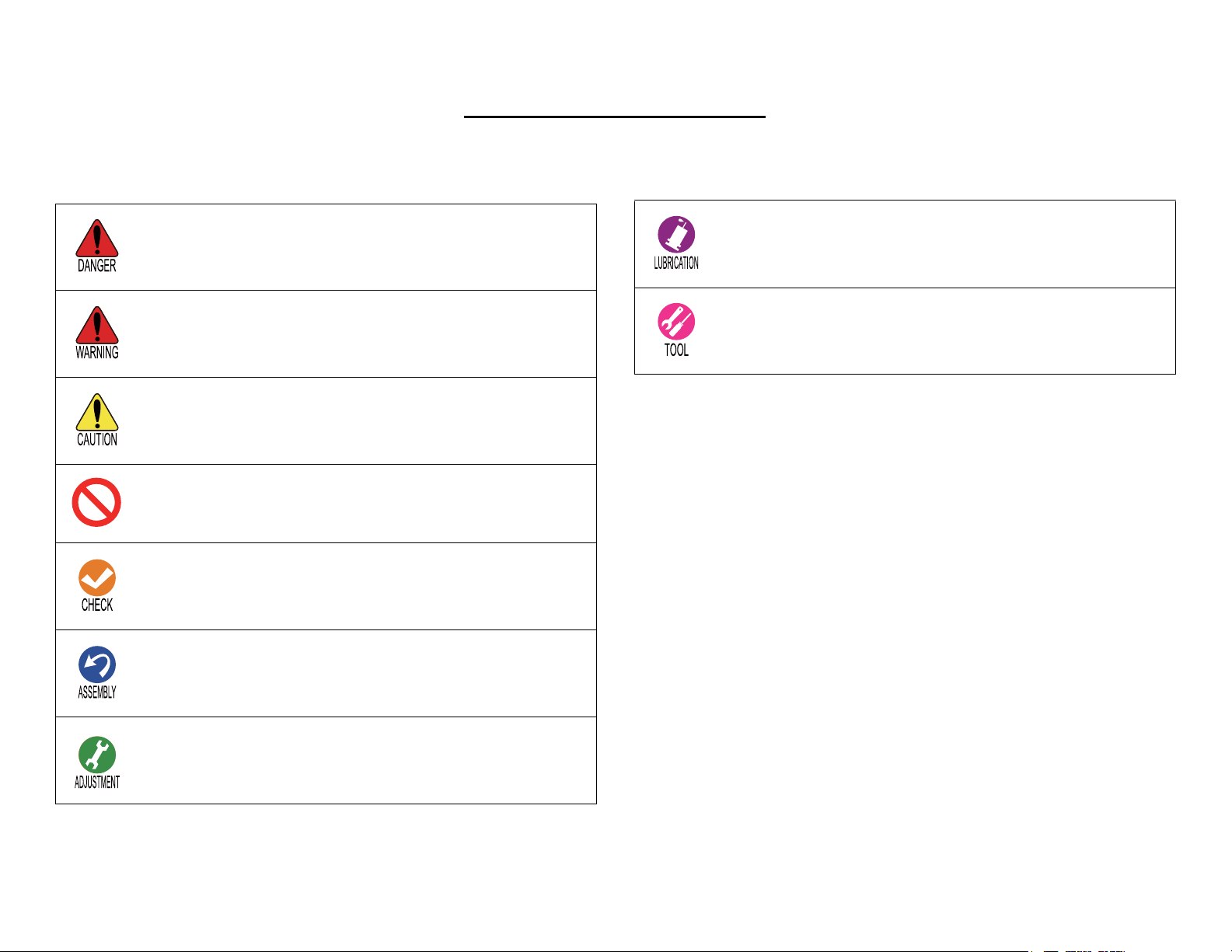
Symbols Used in this Manual
Various symbols are used throughout this manual either to provide additional information on a specific topic or to warn of possible danger present during a procedure or an action.
Pay attention to all symbols when they are used, and always read explanation thoroughly and follow the instructions.
Indicates an operating or maintenance procedure, practice or
condition that, if not strictly observed, would result in injury
or loss of life.
Indicates an operating or maintenance procedure, practice or
condition that, if not strictly observed, could result in injury
or loss of life.
Indicates an operating or maintenance procedure, practice or
condition that, if not strictly observed, could result in
personal injury or may cause damage to, or destruction of
equipment.
Indicates a prohibited action.
Notes have important information and useful tips on the
operation of your equipment.
Indicates that a particular task must be carried out according
to a certain standard after disassembly and before
reassembly, otherwise the quality of the components in
question may be adversely
Indicates an operating or maintenance procedure, practice,
or condition that is necessary to keep the product's quality.
Indicates a lubrication point, practice, or condition that is
necessary to keep the product's quality.
Indicates that special tools and jigs are required.
For Chapter 3 “Disassembly/Reassembly”, symbols other than indicated above
are used to show additional information for disassembly/reassembly. For the
details on those symbols, see "3.3.3 Disassembly Flowchart (p108)".
Confidential
Page 7

Revision Status
Revision Date of Issue Description
A August 21, 2020 First release
Confidential
Page 8

EPSON WF-7820 Series, WF-7830 Series, WF-7840 Series/EC-C7000 Revision A
Contents
Chapter 1 Operating Principles
1.1 Overview .............................................................................................................. 11
1.1.1 Printhead...................................................................................................... 11
1.1.2 Carriage Mechanism / APG Mechanism..................................................... 12
1.1.3 Paper Loading/Feed Mechanism ................................................................. 13
1.1.4 Ink System Mechanism................................................................................ 14
1.1.5 Scanner Mechanism..................................................................................... 15
1.1.6 ADF Mechanism.......................................................................................... 16
1.1.7 List of Motor and Sensor ............................................................................. 18
1.2 APG Mechanism Operating Principles ................................................................ 20
1.2.1 Overview...................................................................................................... 20
1.2.2 Operating Principles .................................................................................... 21
1.2.2.1 Driving Path.........................................................................................21
1.2.2.2 PG Type ...............................................................................................22
1.3 Paper Loading/Feed Mechanism Operating Principles........................................ 23
1.3.1 Overview...................................................................................................... 23
1.3.1.1 Paper Feeding Path ..............................................................................24
1.3.2 Operating Principles .................................................................................... 27
1.3.2.1 Driving Path.........................................................................................27
1.3.2.2 Pre-paper Loading................................................................................ 34
1.3.2.3 Stacker Auto Open/Close Mechanism.................................................35
1.4 Ink System Mechanism ........................................................................................ 37
1.4.1 Overview...................................................................................................... 37
1.4.1.1 Mechanical Configuration ...................................................................37
1.4.1.2 Cleaning............................................................................................... 38
1.4.1.3 Controlling Waste Ink..........................................................................38
1.4.2 Operating Principles .................................................................................... 39
1.4.2.1 Drive Path ............................................................................................39
1.4.3 Operation of Each Mechanism .................................................................... 41
1.4.3.1 Pump Mechanism.................................................................................41
1.4.3.2 Cap Mechanism ................................................................................... 42
1.4.3.3 Carriage Lock Mechanism................................................................... 43
1.4.3.4 Wiper Mechanism................................................................................43
1.4.3.5 Venting Valve...................................................................................... 44
Chapter 2 Troubleshooting
2.1 Troubleshooting.................................................................................................... 46
2.1.1 Troubleshooting Workflow ......................................................................... 46
2.2 Power-On Sequence ............................................................................................. 49
2.3 Fatal Error Code List............................................................................................ 50
2.3.1 Displaying the Fatal Error Code.................................................................. 50
2.3.2 Fatal Error Code .......................................................................................... 50
2.3.2.1 ADF/Scanner ....................................................................................... 51
2.3.2.2 Printer (CR)..........................................................................................58
2.3.2.3 Printer (PF) ..........................................................................................61
2.3.2.4 Printer (ASF)........................................................................................63
2.3.2.5 Printer (2nd ASF: WF-7830 Series/WF-7840 Series/EC-C7000 only)
.......................................................................................................................... 66
2.3.2.6 Printer (I/S) ..........................................................................................68
2.3.2.7 Printer (Stacker)...................................................................................70
2.3.2.8 Printer (RASF: WF-7820 Series/WF-7840 Series/EC-C7000 only) ... 72
2.3.2.9 Printer (Head/CSIC) ............................................................................ 74
2.3.2.10 Printer (Others) .................................................................................. 76
2.3.2.11 System Error ......................................................................................78
2.4 Service Support Mode.......................................................................................... 79
2.4.1 Overview ..................................................................................................... 79
2.4.2 Structure of service support mode menu ..................................................... 79
2.4.3 Service Support Mode startup and operating procedures............................ 79
2.4.4 Status Sheet Information ............................................................................. 82
Confidential
8
Page 9

EPSON WF-7820 Series, WF-7830 Series, WF-7840 Series/EC-C7000 Revision A
Chapter 3 Disassembly/Assembly
3.1 Overview .............................................................................................................. 97
3.1.1 Tools ............................................................................................................ 97
3.1.2 Jigs............................................................................................................... 97
3.1.3 Locations of the Parts/Units......................................................................... 98
3.1.4 Standard Operation Time for Servicing the Product ................................... 99
3.2 Common Cautions on Disassembly/Reassembly ............................................... 105
3.3 Disassembly/Reassembly Procedures ................................................................ 107
3.3.1 Parts/Components Need to be Removed Before Disassembly/Reassembly
............................................................................................................................. 107
3.3.2 Functional differences between models and component parts .................. 107
3.3.3 Disassembly Flowchart.............................................................................. 108
3.3.3.1 WF-7820 Series/WF-7840 Series/EC-C7000.................................... 109
3.3.3.2 WF-7830 Series ................................................................................. 115
3.3.4 Repairing Major Components Disassembly/Assembly Procedure............ 121
3.3.4.1 Maintenance Box ...............................................................................121
3.3.4.2 Housing Left ......................................................................................121
3.3.4.3 Housing Right....................................................................................124
3.3.4.4 Rear ASF Cover Assy (WF-7820 Series/WF-7840 Series/EC-C7000
only) ................................................................................................................126
3.3.4.5 ADF/Scanner Unit .............................................................................128
3.3.4.6 Printhead ............................................................................................129
3.3.4.7 Housing Upper...................................................................................133
3.3.4.8 Inksystem Unit...................................................................................134
3.3.4.9 2nd Bin Assy (WF-7830 Series/WF-7840 Series/EC-C7000 only) ..137
3.3.4.10 Main Board ...................................................................................... 138
3.3.4.11 Rear ASF Unit (WF-7820 Series/WF-7840 Series/EC-C7000 only)
......................................................................................................................... 140
3.3.4.12 CR Unit w/CR Guide Shaft.............................................................. 143
3.3.4.13 Paper Guide Upper Left/Paper Guide Upper Center/Paper Guide Upper
Right................................................................................................................146
3.3.4.14 Porous Pad A/Porous Pad B.............................................................148
3.4 Detailed Disassembly/Reassembly Procedure for each Part/Unit...................... 152
3.5 Routing FFCs/cables .......................................................................................... 156
Chapter 4 Adjustment
4.1 Required Adjustments....................................................................................... 161
4.2 Adjustment Program........................................................................................... 166
4.2.1 Operating Environment ............................................................................. 166
4.2.2 Adjustment and Inspection List................................................................. 166
4.2.3 Details of the Adjustment Program ........................................................... 171
4.2.3.1 Adjustment (Print Adjustment by Program)...................................... 171
4.3 Mechanism Adjustment / Check ........................................................................ 178
4.3.1 PG Adjustment .......................................................................................... 178
4.3.1.1 PG Adjustment procedure..................................................................178
4.3.1.2 Preparation.........................................................................................178
4.3.1.3 PG adjustment procedure...................................................................181
4.3.1.4 Checking the Platen Gap.................................................................... 183
Chapter 5 Maintenance
5.1 Cleaning.............................................................................................................. 185
5.1.1 Cleaning the CR Unit ................................................................................ 185
5.1.2 Cleaning the Exterior Parts/inside of the printer ....................................... 186
5.2 Lubrication ......................................................................................................... 186
5.2.1 Lubrication Points and Instructions........................................................... 187
Chapter 6 Appendix
6.1 Connection Diagram........................................................................................... 193
6.2 Head Fuse........................................................................................................... 194
6.3 Protection for Transportation ............................................................................. 195
6.3.1 Securing the CR Unit................................................................................. 195
6.3.2 Protection of Stacker Assy ........................................................................ 196
6.3.3 Protection of Cassette Cover ..................................................................... 196
6.3.4 Protection of Scanner Unit ........................................................................ 197
6.3.5 Protection of Paper Support
(WF-7820 Series/WF-7840 Series/EC-C7000 only) ........................................... 198
6.3.6 Securing the ADF Document Support....................................................... 198
6.3.7 Securing the Paper Support Cover
(WF-7820 Series/WF-7840 Series/EC-C7000 only) ........................................... 199
6.3.8 Securing the Maintenance Box.................................................................. 199
Confidential
9
Page 10

OPERATING PRINCIPLES
CHAPTER
1
Confidential
Page 11
EPSON WF-7820 Series, WF-7830 Series, WF-7840 Series/EC-C7000 Revision A
A#3
A#2
A#1
A#400
A#399
A#398
B#400
B#399
B#398
B#3
B#2
B#1
C#3
C#2
C#1
C#400
C#399
C#398
D#400
D#399
D#398
D#3
D#2
D#1
C#136
C#129
C#128
D#136
C#137
D#137
D#129
D#128
C#272
C#265
C#264
D#272
C#273
D#273
D#265
D#264
0.085 mm
1/300 inch)
8.636 mm
(204/600 inch
)
1.016 mm
(24/600 inch)
)
0.042 mm
1/600 inch)
)
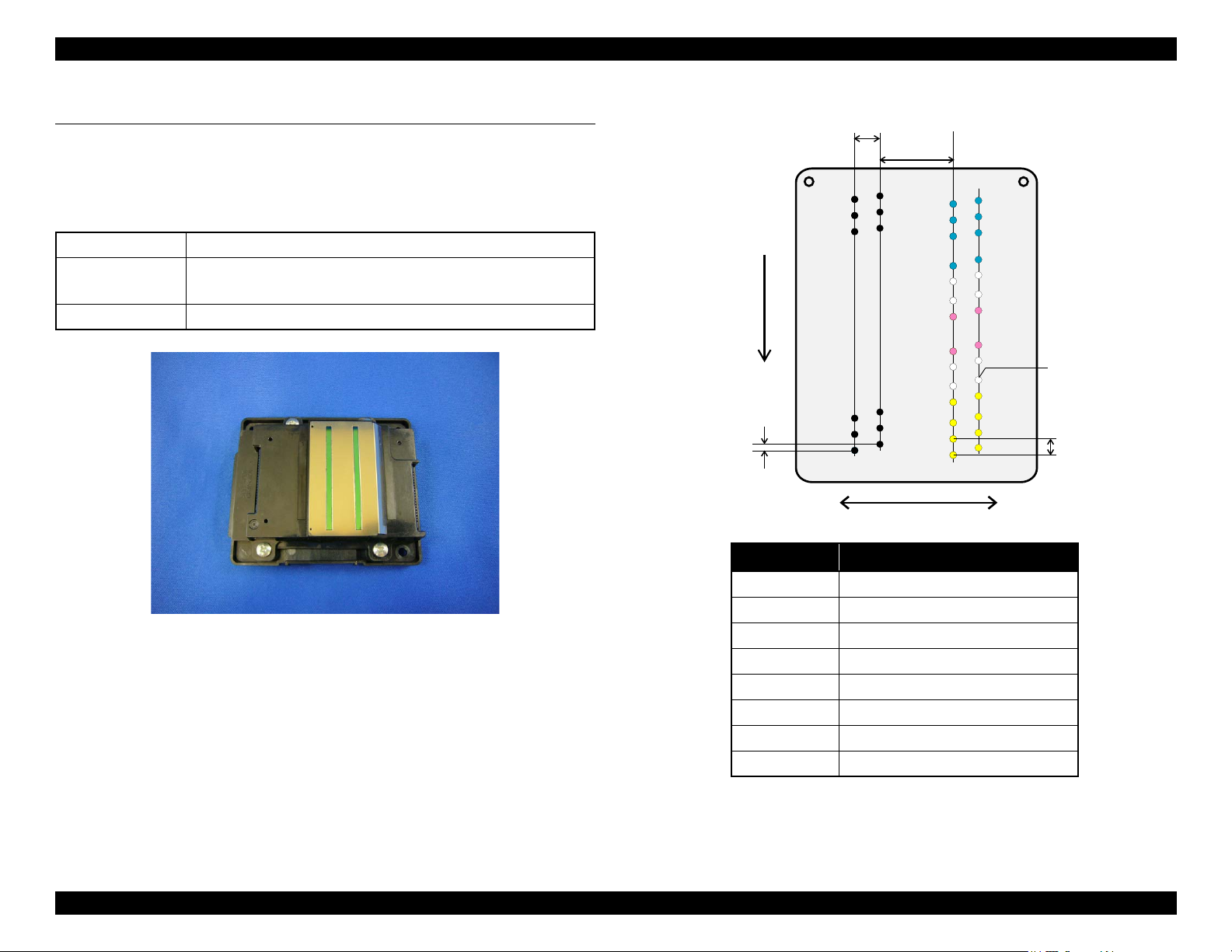
Black
Column A
Column B
Column C
Column D
Carriage movement direction
Paper feed direction
Column Color
ABk
BBk
C #1~#128 Y
C #137~#264 M
C #273~#400 C
D #1~#128 Y
D #137~#264 M
D #273~#400 C
Yellow
Cyan
Magenta
Not used
1.1 Overview
This chapter describes overview of each mechanism inside the printer.
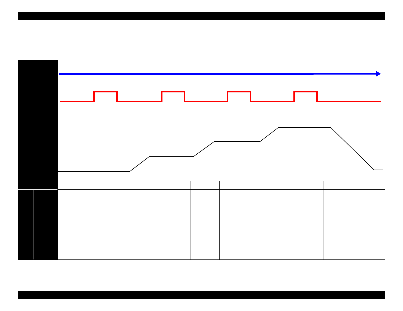
1.1.1 Printhead
Table 1-1. μTFP2 Head Nozzle Configuration
Color Bk, C, M, Y (four colors)
Number of nozzles 1568 nozzles
(Bk: 400 nozzles x 2 columns / Y, M, C: 256 nozzles per color)
Nozzle pitch 300 dpi
Figure 1-1. μTFP2 Head Appearance
Figure 1-2. μTFP2 Head Nozzle Layout
Confidential
Operating Principles Overview 11
Page 12
EPSON WF-7820 Series, WF-7830 Series, WF-7840 Series/EC-C7000 Revision A
CR Scale
Main Frame
CR Guide Shaft
CR Unit
CR Timing Belt
Eccentric Cam
Eccentric
Cam
CR Motor
(Backside of the Main Frame)
CR Unit
Section view
Main Frame
CR Guide Shaft
CR Encoder
CR Scale
CR Unit
Rear
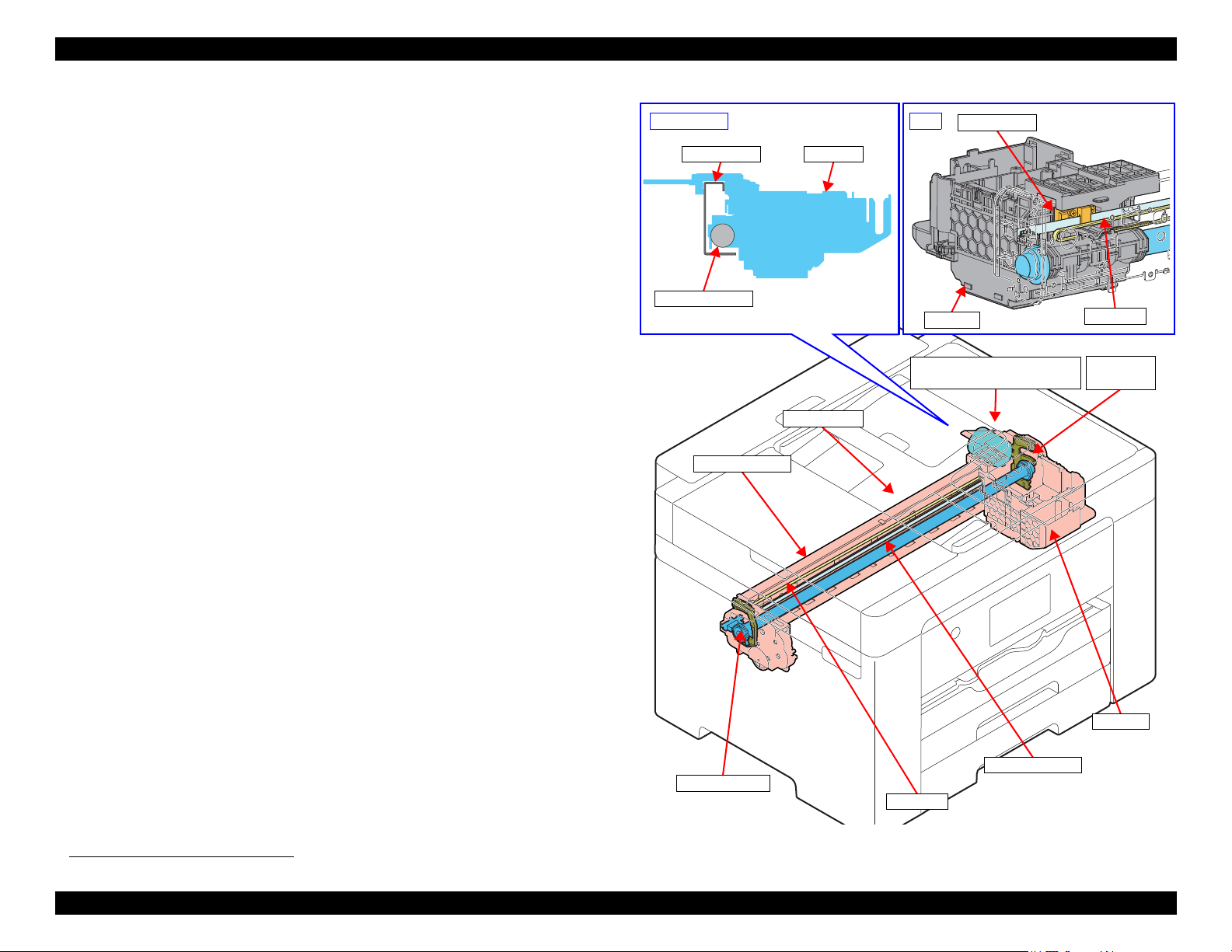
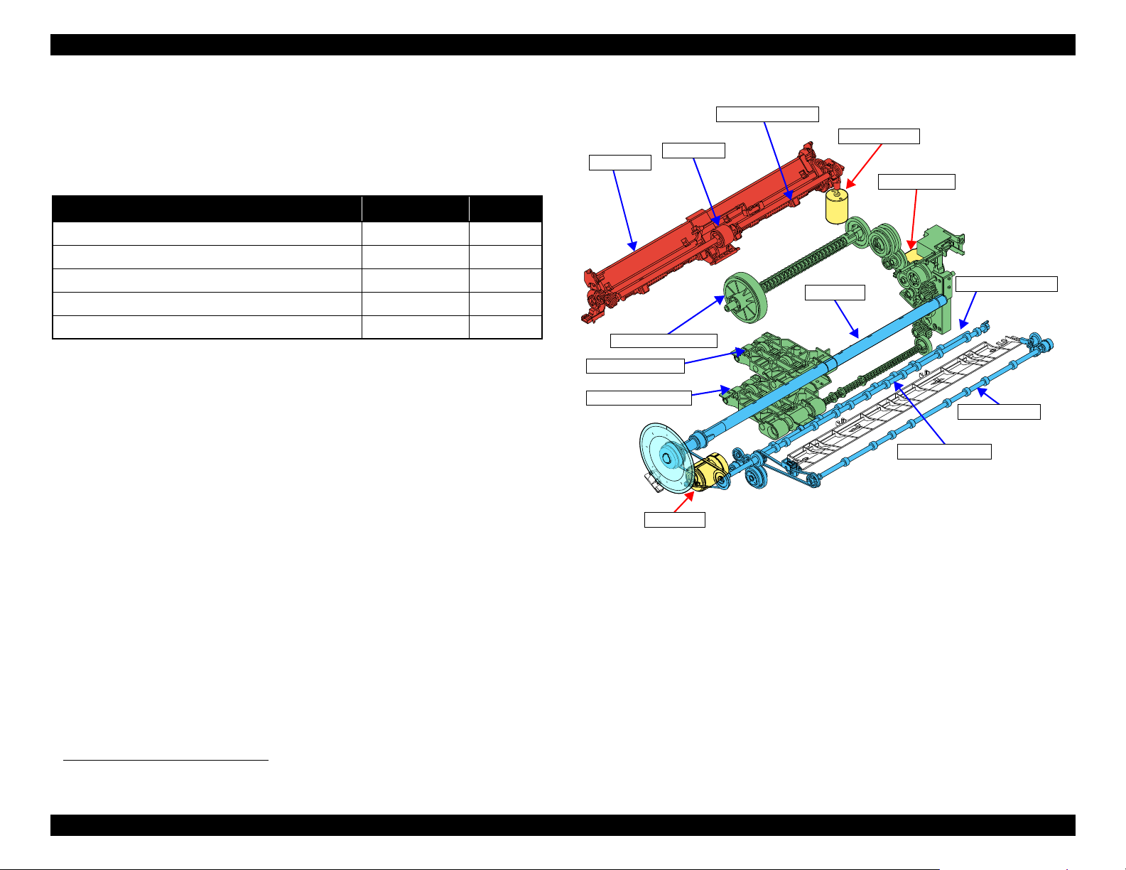
1.1.2 Carriage Mechanism / APG Mechanism
The carriage mechanism is consist of CR Unit, CR Encoder, CR Scale, CR
Motor, CR Timing Belt, and etc. The carriage mechanism is a key mechanism
to ensure stable print quality because printing is performed by moving the CR
Unit from side to side.
The CR Unit is supported by the CR Guide Shaft and by the Main Frame.
When the CR Motor rotates, and drive force is transmitted to the CR Timing
Belt, the CR Unit fastened to the CR Timing Belt moves to the left and right to
implement printing.
The position and speed of the CR Unit are always monitored by the CR
Encoder and CR Scale, and the CR Motor is controlled in accordance with the
information acquired by the CR Encoder.
*1
The APG mechanism
the paper (PG: Platen Gap) as suitable, depending on the paper to be printed.
When the PF Motor drive force rotates the CR Guide Shaft via the APG Mechanism, the CR Guide Shaft is raised and lowered by the Eccentric Cams
mounted to both ends of the CR Guide Shaft. With this, the CR Unit supported
by the CR Guide Shaft rises and lowers, and the Platen Gap is set properly.
adjusts the distance between the printhead nozzle and
Operating Principles Overview 12
*1. See "1.2 APG Mechanism Operating Principles" (p 20) for the details of the APG mechanism.
Figure 1-3. Carriage Mechanism
Confidential
Page 13
EPSON WF-7820 Series, WF-7830 Series, WF-7840 Series/EC-C7000 Revision A
Paper feed mechanism
(includes Duplex Unit)
Front paper loading
mechanism
Rear paper loading mechanism
Cassette
Stacker auto open/close
mechanism
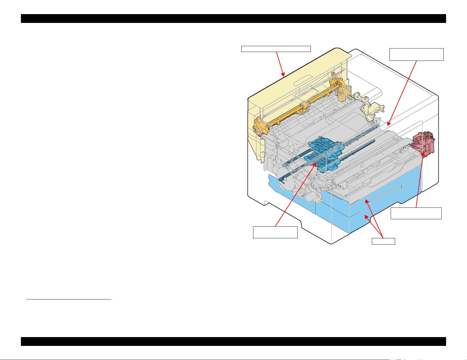
1.1.3 Paper Loading/Feed Mechanism
This product employs the front paper loading*1 and the rear paper loading*2
mechanism. This also supports automatic duplex printing. The lower path that
is independent to the paper conveyance path for printing has been added as the
paper turn-over path for duplex printing.
Each mechanisms are driven by the ASF Motor, RASF Motor*2, and PF Motor.
Also, the throughput for continuous printing and duplex printing is
dramatically improved compared to conventional models by mounting “Prepaper Loading” that loads the next page while printing.
The Auto Open/Close Mechanism for the Stacker has been installed. This
functions automatically to pull out the Stacker to correspond to the size of the
paper being printed. The Auto Open/Close Mechanism for the Stacker operates
using the drive force of the STK Motor.
*3
Figure 1-4. Paper Loading/Feed Mechanism
*1. WF-7820 Series: one cassette
WF-7830 Series/WF-7840 Series/EC-C7000: two cassettes
*2. Except for WF-7830 Series
*3. See "1.3 Paper Loading/Feed Mechanism Operating Principles" (p 23) for more details.
Operating Principles Overview 13
Confidential
Page 14
EPSON WF-7820 Series, WF-7830 Series, WF-7840 Series/EC-C7000 Revision A
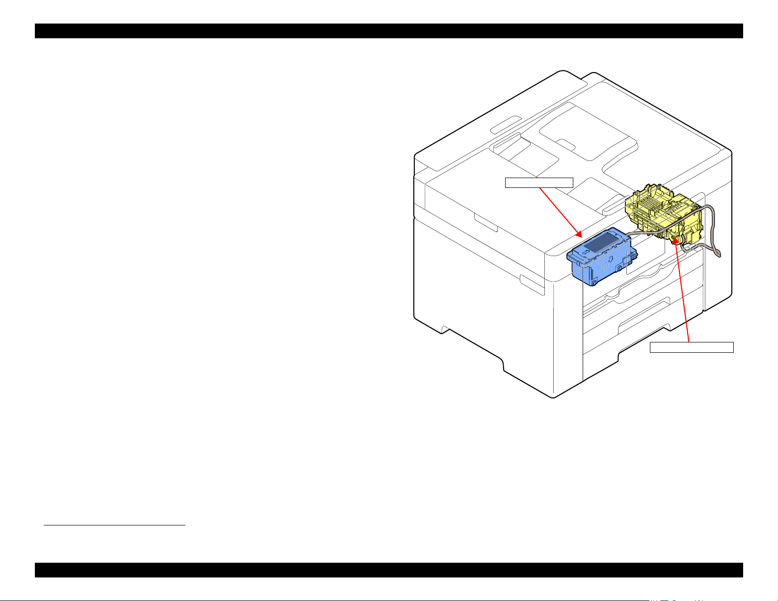
Ink System Mechanism
Maintenance Box
Ink system mechanism
1.1.4 Ink System Mechanism
The major components of the ink system mechanism*1 are a Cap, Pump Unit,
and Waste Ink Tube.
The ink system mechanism employs the direct acting type for capping. The
Pump Motor drives the pump mechanism, capping mechanism, wiper mechanism, carriage lock mechanism, and venting valve mechanism to clean the
Printhead.
User replaceable Maintenance Box is installed to this product. A CSIC
mounted on the Maintenance Box keeps track of how much waste ink has been
collected.
Figure 1-5. Ink System Mechanism
*1. See "1.4 Ink System Mechanism" (p 37) for more details.
Operating Principles Overview 14
Confidential
Page 15
EPSON WF-7820 Series, WF-7830 Series, WF-7840 Series/EC-C7000 Revision A
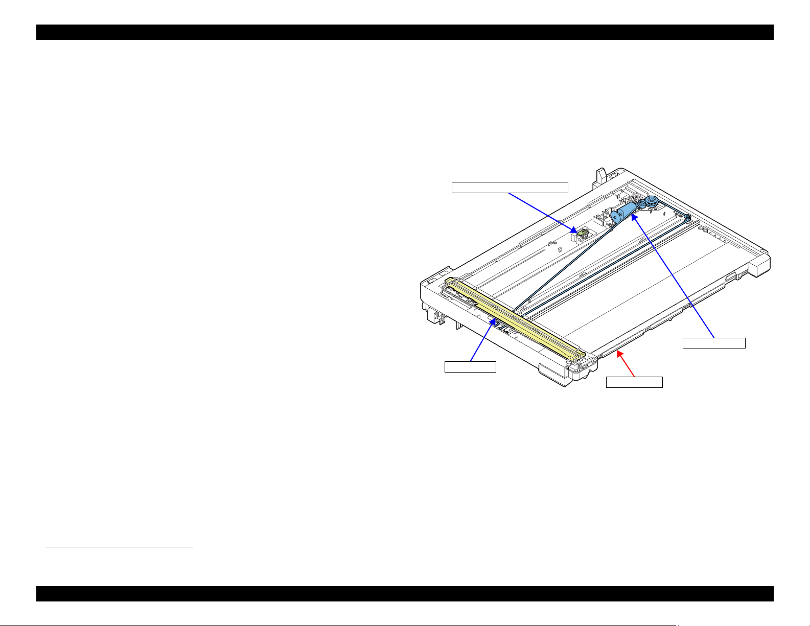
Scanner Unit
CIS Module
Scanner Motor
Scanner Document Size Sensor*
Note " * " : Except for WF-7830 Series
1.1.5 Scanner Mechanism
The scanner mechanism consists of a Scanner Motor that drives the Scanner
Carriage equipped with the CIS Module that scans documents and the Scanner
*1
Document Size Sensor
of this printer, the CIS module moves using a timing belt, scanning documents.
that detects the document size. For the Scanner Unit
Figure 1-6. Scanner Mechanism
*1. Except for WF-7830 Series
Operating Principles Overview 15
Confidential
Page 16
EPSON WF-7820 Series, WF-7830 Series, WF-7840 Series/EC-C7000 Revision A
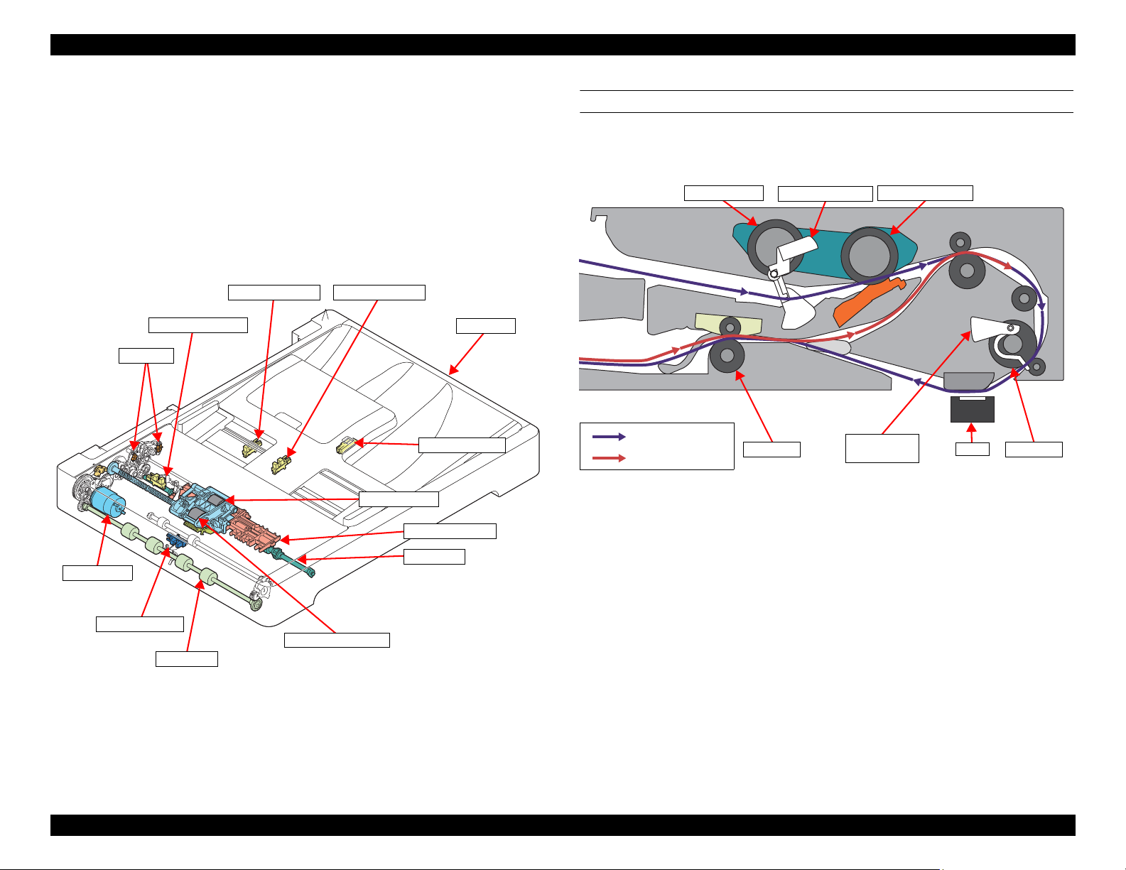
EJ Roller
Pickup Roller
ADF Unit
ADF Motor
Solenoid
PF Roller
ADF PE Sensor
ADF DOC Sensor
ADF PW Sensor
ADF PL Sensor*
EJ Driven Roller
Separation Roller
ADF PW Sensor*
Note " *" : Except for WF-7830 Series
Pickup Roller Separation Roller
EJ Roller
CIS
Lever of ADF
PE Sensor
ADF DOC Lever
PF Roller
Front side scanning
Rear side scanning
1.1.6 ADF Mechanism
The ADF mechanism uses a stationary image sensor that scans documents
transported by the mechanism. It consists of ADF Motor, ADF Encoder, ADF
PE Sensor, ADF DOC Sensor, ADF PW Sensor, ADF PL Sensor, PF Roller, EJ
Roller, Pickup Roller and etc.
The mechanism is also capable of turning over the documents when finished
scanning their one side, and then scanning the other side (automatic doublesided scanning).
DOCUMENT FEED PATH
When scanning document, the document is fed inside the ADF as shown
below.
Figure 1-8. Document Feed Path
Operating Principles Overview 16
Figure 1-7. ADF Mechanism
Confidential
Page 17
EPSON WF-7820 Series, WF-7830 Series, WF-7840 Series/EC-C7000 Revision A
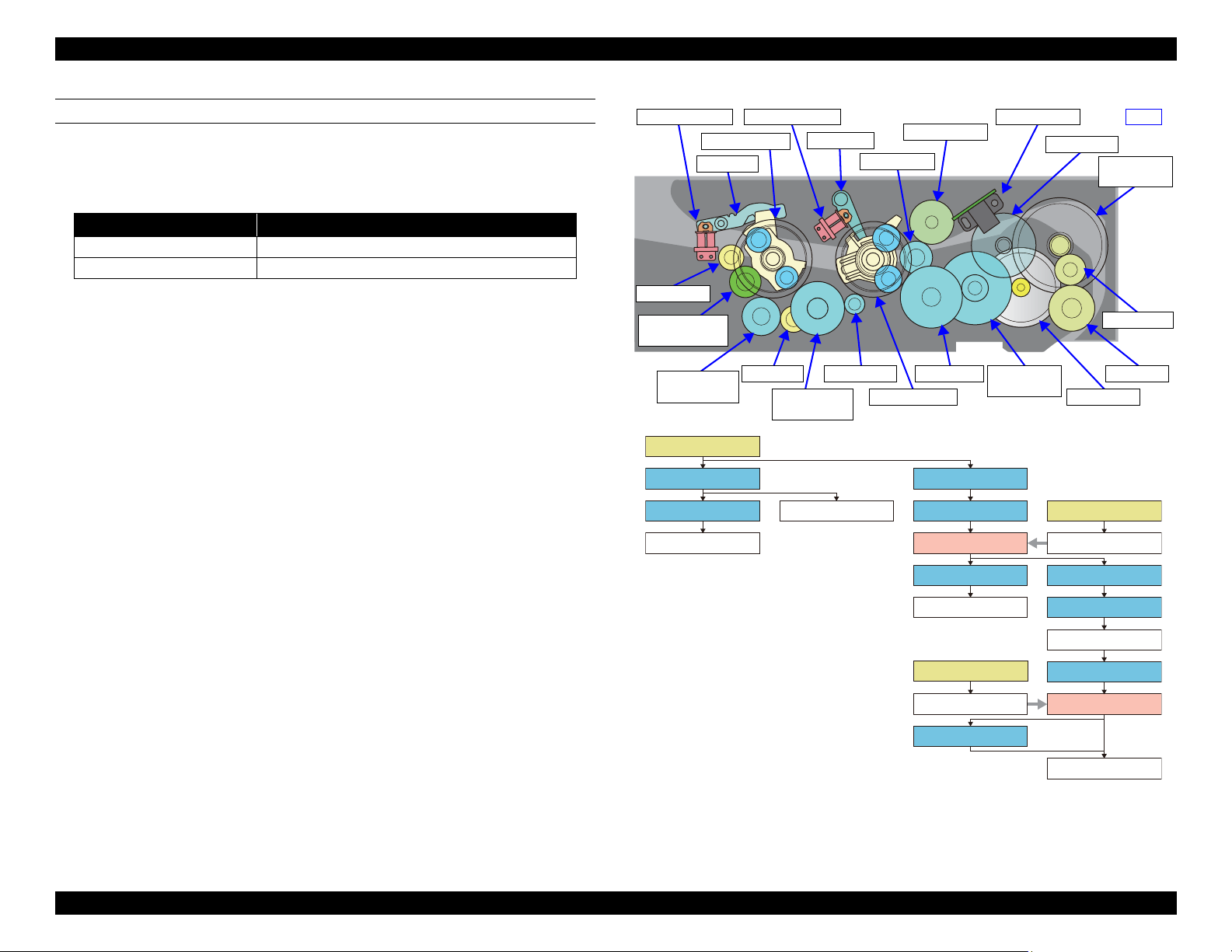
ADF Motor
PF Roller
ADF Scale
ADF Encoder
Pickup Roller
LD planet gear
ADF Solenoid 1ADF Solenoid 2
EJ Roller
EJ intermittent
gear
EJ planet gear
Combination
gear 4
Spur gear E
Spur gear D
Spur gear B
Combination
gear 3
Combination
gear 2
Spur gear A
Combination
gear 1
Rear
Spur gear C
ADF Motor
Combination gear 1 Combination gear 2
Spur gear A
PF Roller
ADF Scale
Spur gear B
LD planet gear
Spur gear C
Pickup Roller
Spur gear D
Combination gear 3
EJ Roller
Combination gear 4
EJ planet gear
Spur gear E
EJ intermittent gear
LD Lever
EJ Lever
LD Lever
EJ Lever
ADF Solenoid 2
ADF Solenoid 1
DRIVING PATH
The ADF Motor, which uses the DC motor, is controlled by the ADF Scale and
the ADF Encoder. The following describes the relationship between the
rotation direction of the ADF Motor and the movement of the ADF.
Rotation direction* Movement
CCW (counter clockwise) Scanning Operation (Paper Loading to Ejection)
CW (clockwise) Turn-over operation for rear side scanning
Note " *": Rotation direction seen from the output shaft side of the motor.
Drive force of the ADF Motor drives the Pickup Roller, PF Roller, EJ Roller,
and EJ intermittent gear in the path shown in Figure 1-9.
The ADF Solenoid 1/2 are used for rotation control of the Pickup Roller, and to
control the rising and lowering of the EJ Driven Roller that passes through the
EJ Intermittent Gear.
When idling
The ADF Solenoid 1/2 are not being energized. At this time, the LD Lever
and the EJ Lever transmit paper-loading direction rotation from the LD
Planet Gear to the Pickup Roller through the Spur Gear C, and maintains
When paper loading originals
them in a state that prevents rising of the EJ Driven Roller that passes from
the EJ Planet Gear through the EJ Intermittent Gear.
By energizing the ADF Solenoid after the ADF Motor starts rotating in the
CCW direction, the LD Lever releases the LD Planet Gear enabling drive
force transmission to the Pickup Roller. The Pickup Roller rotates in the
paper-loading direction and the Separation Roller is lowered.
Operating Principles Overview 17
Figure 1-9. Driving Path
Confidential
Page 18
EPSON WF-7820 Series, WF-7830 Series, WF-7840 Series/EC-C7000 Revision A
D
B
E
7
8
2
5
12
9
4
A
C
6
3
11
10
1
13
14
15
17
16
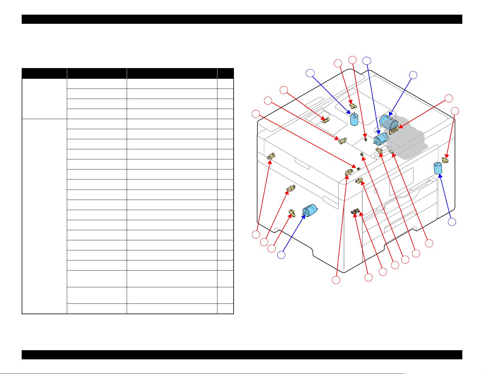
1.1.7 List of Motor and Sensor
This section describes the types and positions of the motors and sensors.
Table 1-2. List of Motor and Sensor (1)
Mechanism name
Carriage
mechanism
Paper loading/
feed mechanism
Motor/Sensor name Motor/Sensor type No.
CR Motor DC Motor D
CR Encoder Transmission-type photo interrupter 17
PW Sensor Reflection-type photo interrupter 15
APG Sensor Transmission-type photo interrupter 7
PF Motor DC Motor B
PF Encoder Transmission-type photo interrupter 8
ASF Motor DC Motor E
ASF Encoder Transmission-type photo interrupter 14
RASF Motor
RASF Encoder
STK Motor DC Motor C
STK Encoder Transmission-type photo interrupter 16
1st Cassette Sensor Mechanical contact 13
2nd Cassette Sensor
PE Sensor Transmission-type photo interrupter 9
PE2 Sensor Transmission-type photo interrupter 12
PE3 Sensor Transmission-type photo interrupter 4
LD Phase Sensor Transmission-type photo interrupter 6
RASF Paper Sensor
Stacker A4 Position
Sensor
Stacker A3 Position
Sensor
Duplex Unit Sensor Mechanical contact 1
*1
*1
*2
*1
Note "*1": WF-7820 Series/WF-7840 Series/EC-C7000 only
"*2": WF-7830 Series/WF-7840 Series/EC-C7000 only
Operating Principles Overview 18
DC Motor A
Transmission-type photo interrupter 2
Mechanical contact 5
Transmission-type photo interrupter 3
Mechanical contact 11
Mechanical contact 10
Figure 1-10. List of Motor and Sensor (1)
Confidential
Page 19
EPSON WF-7820 Series, WF-7830 Series, WF-7840 Series/EC-C7000 Revision A
H
F
G
28
30
25
29
26
20
19
18
21
21
27
24
22
23
34
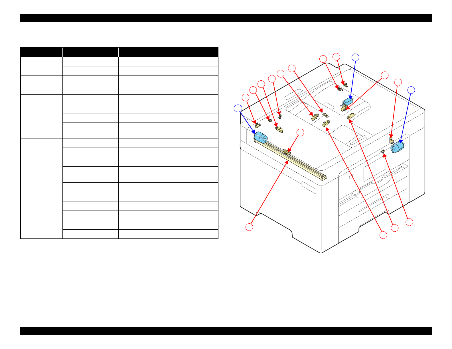
Table 1-3. List of Motor and Sensor (2)
Mechanism name
Ink system
mechanism
Others PIS Sensor Reflection-type photo interrupter
Scanner Scanner Motor DC Motor F
ADF Unit ADF Motor DC Motor G
Motor/Sensor name Motor/Sensor type No.
Pump Motor DC Motor H
Pump Encoder Transmission-type photo interrupter 29
Scanner Open Sensor Mechanical contact 28
Scanner Encoder Transmission-type photo interrupter 30
CIS Module CIS 26
Scanner Document
Size Sensor
*1
Reflection-type photo interrupter 20
ADF Encoder Transmission-type photo interrupter 25
ADF Close Sensor
ADF Half Close
*1
Sensor
ADF PW Sensor (x2)
ADF PL Sensor
ADF Solenoid 1 Solenoid 24
ADF Solenoid2 Solenoid 22
ADF DOC Sensor Transmission-type photo interrupter 23
ADF PE Sensor Transmission-type photo interrupter 34
*1
*1
Mechanical contact 19
Mechanical contact 18
*2
Transmission-type photo interrupter 21
Transmission-type photo interrupter 27
Note "*1": WF-7820 Series/WF-7840 Series/EC-C7000 only
"*2": Only rear side one is equipped on WF-7830 Series.
Figure 1-11. List of Motor and Sensor (2)
Operating Principles Overview 19
Confidential
Page 20
EPSON WF-7820 Series, WF-7830 Series, WF-7840 Series/EC-C7000 Revision A
CR Unit
CR Guide Shaft
APG Cam Left
APG Cam Right
PG Adjust Cam Left
PG Adjust Cam Right
APG Change Gear
APG Sensor
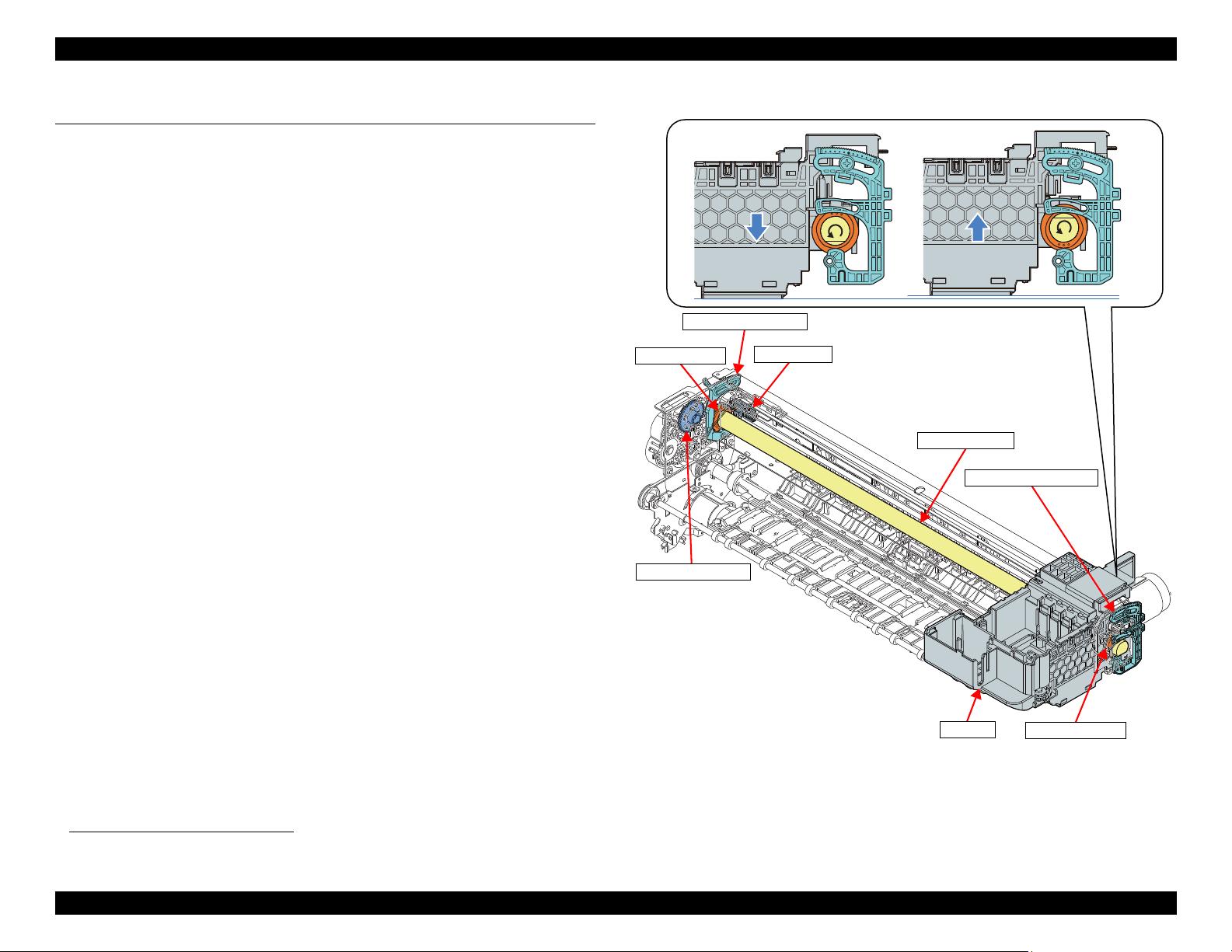
1.2 APG Mechanism Operating Principles
The APG Mechanism rotates the Cams at both ends of the CR Guide Shaft that
supports the CR Unit with the drive force of the PF Motor, and switches the PG
(4 types).
1.2.1 Overview
The APG Mechanism is composed of the APG Change Gear that switches
drive force transmission from the PF Motor, the APG Sensor that detects the
PG Position, and the APG Cams (left/right) on both ends of the CR Guide
Shaft.
The APG Sensor that detects each PG Position adopts the transmission-type
photo interrupter. When the drive force of the PF Motor is transmitted to the
APG Cams by the APG Change Gear, the APG Cams rotate along with the
rotation of the PF Motor. The PG Position detection flag is mounted to the
APG Cam Left. When the flag passes through the slit in the APG Sensor, it
detects the PG Position.
The APG Cams on both ends of the CR Guide Shaft are installed on top of each
of the PG Adjust Cams (left/right). When the APG Cams are rotated by the
drive force from the PF Motor, the CR Guide Shaft moves up and down using
the PG Adjust Cams as pivot points. This action switches the PG.
*1
*1. See "1.2.2 Operating Principles" (p 21).
Operating Principles APG Mechanism Operating Principles 20
Figure 1-12. APG Mechanism
Confidential
Page 21
EPSON WF-7820 Series, WF-7830 Series, WF-7840 Series/EC-C7000 Revision A
PF Motor
PF Roller
PF Timing Belt
EJ Roller
Center
APG Cam Left/
CR Guide Shaft
APG Change Gear
Full side
Combination gear A
Spur gear1
Combination
gear B
Spur gear 2
Combination gear D
Combination gear C
APG Change Gear
APG Cannot Switch
APG Can Switch
The gear train that transmits drive force from
the APG Change Gear and the PF Motor, and
the gear that rotates the APG Cams on the
ends of the CR Guide Shaft are not engaged
with the tension of the spring.
Drive force from the PF Motor is
transmitted to the APG Cams on the ends of
the CR Guide Shaft by the CR Unit pushing
the APG Change Gear.
CR Unit
APG Sensor
Top
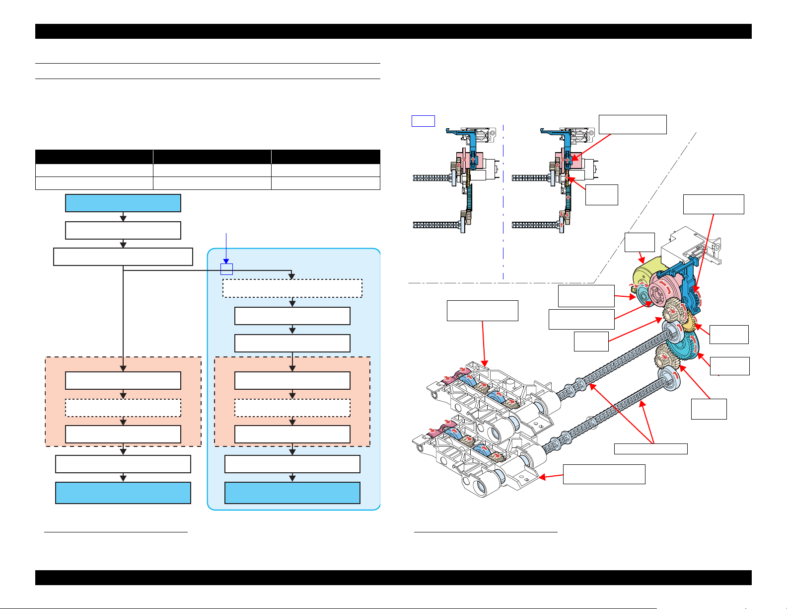
1.2.2 Operating Principles
1.2.2.1 Driving Path
The APG Change Gear in the APG Unit transmits drive force of the PF Motor
to the APG Cams by the engaging of the gear train that transmits drive force
from the PF Motor and the gear that rotates the APG Cams on the ends of the
CR Guide Shaft.
This APG Change Gear is normally in an disengaged state with each gear train
by the compression spring. This prevents the PG from being changed when
conveying paper because the PF Motor drives the PF Roller and EJ Roller.
To change the PG, push the APG Change Gear by moving the CR Unit to the
Full side. By doing this, drive force of the PF Motor switches to a state to be
transmitted to the APG Cams by each gear train and the APG Change Gear
engaging.
The PG change is detected by the APG Sensor. The output of the APG Sensor
is High when the flag on the APG Cam Left is in the slit in the APG Sensor.
Figure 1-13. Driving Path
Operating Principles APG Mechanism Operating Principles 21
Confidential
Page 22
EPSON WF-7820 Series, WF-7830 Series, WF-7840 Series/EC-C7000 Revision A
(When the PF Motor rotates further in the CW direction from the state of PG4, it transitions again to PG1.)
CW
High High High HighLow Low Low Low Low
1.5
1.85
2.35
3.0
1.2.2.2 PG Type
This product has four types of PGs. The following describes the details of PGs. If the PG position is unknown for some reason, set it to PG1 using the APG reset
operation.
PF Motor
rotation
direction*
APG Sensor
Output
PG (mm)
PG position
Printing
Application
Not
printing
Note " *": Rotation direction seen from the output shaft side.
Operating Principles APG Mechanism Operating Principles 22
--- PG1 --- PG2 --- PG3 --- PG4 ---
---
• Printing plain
paper (Single)
default
• Special paper
(Glossy paper)
---
• Initialization
when turning
power ON
• When turning
power OFF
• Plain paper: Fine
• Duplex printing
• Avoid rubbing
in high speed
(Bi-d)
• Special paper
(matte paper)
---
• Avoid rubbing
(Uni-d)
---
--- ---
• Envelope (Unid)
• Avoid rubb ing at
PG3
---
• Cleaning
(wiping)
Confidential
Page 23

EPSON WF-7820 Series, WF-7830 Series, WF-7840 Series/EC-C7000 Revision A
LD Roller*
LD Roller*
PF Roller
EJ Roller Center
Holder Cam Assy
Change Slider
PF Encoder
Paper Support*
Paper Cassette
Stacker
STK Motor
PF Motor
Intermediate
Roller
Pickup Roller
Assy
RASF Motor*
EJ Roller Front
PE1 Sensor
PE3 Sensor
PE2 Sensor
ASF Motor
Intermediate
Roller
Note " * " : Except for WF-7830 Series
1.3 Paper Loading/Feed Mechanism Operating Principles
1.3.1 Overview
The following describes the relationship between each mechanism relating to
paper loading and paper feeding, and the drive motors/sensors. The DC Motor
is used in each mechanism so the rotary encoder is used for control.
Function Power source Configuration
With front paper loading enabled by the Change Lever, the ASF
Front paper
loading
Rear paper
loading
Paper feeding/
Auto duplex
printing
(paper
reversing)
Stacker open/
close
*2
ASF Motor
RASF Motor
ASF Motor
PF Motor
ASF Motor
STK Motor
Note "*1" : Except for WF-7820 Series
"*2": Except for WF-7830 Series
Motor drives the Pickup Roller Assy (Paper Cassette 1st/Paper
Cassette 2nd
the cassette to the PF Roller. Select Paper Cassette 1st or Paper
Cassette 2nd with the rotation direction of the ASF Motor and the
Change Slider position.
The paper conveyance state is detected by the PE3 Sensor near the
Intermediate Roller and the PE1 Sensor in front of the PF Roller.
The LD Roller is rotated by driving the RASF Motor to convey
paper from the Rear ASF to the Intermediate Roller.
The state of the LD Roller is detected by the LD Phase Sensor.
Drive the Intermediate Roller to convey paper from the
Intermediate Roller to the PF Roller. The paper conveyance state
is detected by the PE3 Sensor near the Intermediate Roller and
the PE1 Sensor in front of the PF Roller.
Drive the PF Roller and the EJ Roller Center to convey the paper
being printed.
Drive the Intermediate Roller to convey paper from the
Intermediate Roller to the PF Roller. The paper conveyance state
is detected by the PE3 Sensor near the Intermediate Roller and
the PE1 Sensor in front of the PF Roller.
If the Stacker is housed in the body, the Stacker is automatically pulled
out when starting printing to correspond to A4 size or to A3 size paper
for the paper to be printed.
Also, when the power supply is turned off, or the like, house the Stacker.
The state of the Stacker is detected by the Stacker A4 Position Sensor
and the Stacker A3 Position Sensor.
*1
) and the Intermediate Roller to convey paper from
Operating Principles Paper Loading/Feed Mechanism Operating Principles 23
Figure 1-14. Paper Loading/Feed Mechanism
Confidential
Page 24
EPSON WF-7820 Series, WF-7830 Series, WF-7840 Series/EC-C7000 Revision A
Paper Cassette 1st
EJ Roller Front
PF Roller
PE1 Sensor
Pickup Roller Assy
Star Wheel Holder
Paper Cassette 2nd
EJ Roller Center
PE1 Sensor
Section view
PE3 Sensor
PE3 Sensor
Star Wheel Holder Center
Star Wheel Holder
Center
Star Wheel
Holder
Paper
Cassette 1st
Intermediate Roller
Intermediate Roller
EJ Roller Center
PF Roller
PE1 Sensor
Pickup Roller Assy
PE1 Sensor
Section view
PE3 Sensor
PE3 Sensor
EJ Roller Front
Star Wheel Holder
Star Wheel Holder Center
Star Wheel
Holder Center
Star Wheel
Holder
Paper Cassette 2nd
Paper Cassette 2nd
Intermediate Roller
Intermediate Roller
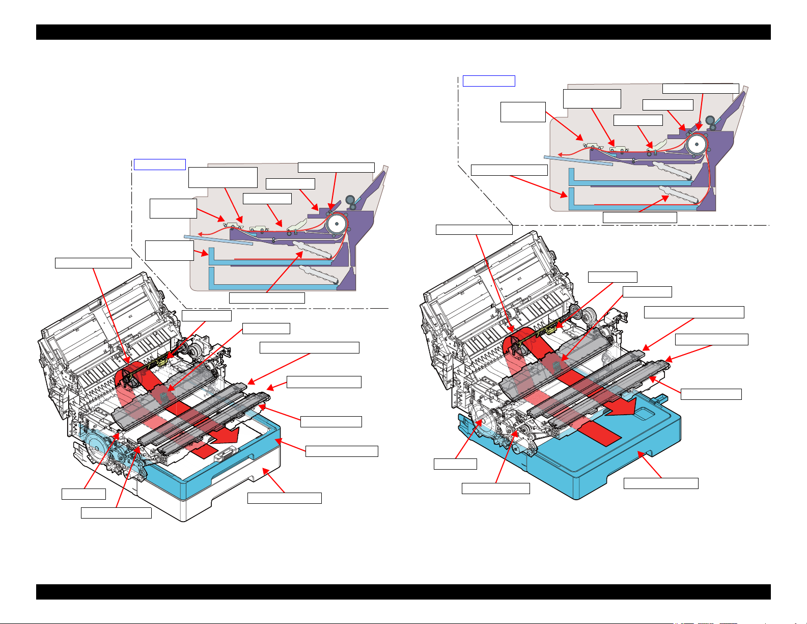
1.3.1.1 Paper Feeding Path
1.3.1.1.1 Front Paper Loading
Paper loaded into the Paper Cassette is fed to the Intermediate Roller by way of
the Pickup Roller Assy, and arrives at the PE1 sensor via PE3 Sensor. Next,
skew is removed, and the paper is printed while being fed using the PF Roller
and EJ Roller Center/EJ Roller Front/Star Wheel Holder.
Figure 1-16. Paper Loading Path When Using Front Paper Loading (2)
Figure 1-15. Paper Loading Path When Using Front Paper Loading (1)
Operating Principles Paper Loading/Feed Mechanism Operating Principles 24
Confidential
Page 25
EPSON WF-7820 Series, WF-7830 Series, WF-7840 Series/EC-C7000 Revision A
Hopper
EJ Roller Front
PF Roller
PE1 Sensor
LD Roller
EJ Roller Center
Hopper
LD Roller
PE1 Sensor
Section view
PE3 Sensor
PE3 Sensor
Star Wheel Holder
Star Wheel Holder Center
Star Wheel
Holder Center
Star Wheel
Holder
Intermediate Roller
Intermediate Roller
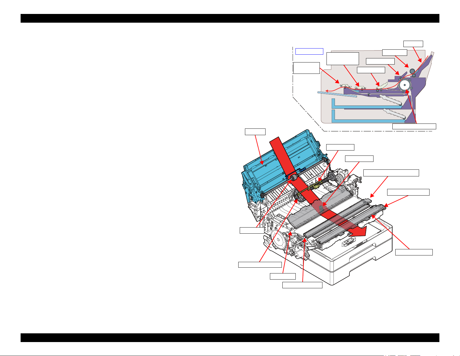
1.3.1.1.2 Rear Paper Loading (Except for WF-7830 Series)
Paper set in the Hopper in the rear of the printer is fed to the PE3 Sensor
position by the LD Roller.
Thereafter, it is conveyed by the Intermediate Roller to the PE1 Sensor
position. After deskewing, printing is implemented while the paper is conveyed
by the PF Roller and EJ Roller Center/EJ Roller Front/Star Wheel Assy.
Operating Principles Paper Loading/Feed Mechanism Operating Principles 25
Figure 1-17. Paper Loading Path When Using Rear Paper Loading
Confidential
Page 26
EPSON WF-7820 Series, WF-7830 Series, WF-7840 Series/EC-C7000 Revision A
EJ Roller Center
PF Roller
PE1 Sensor
Section view
EJ Roller Front
Upper path
Lower path
Change Flap (descent)
Change Flap (rise)
Lower Path Roller
EJ Roller Front
PE1 Sensor
PE3 Sensor
PE3 Sensor
PE1 Sensor
Intermediate Roller
Intermediate Roller
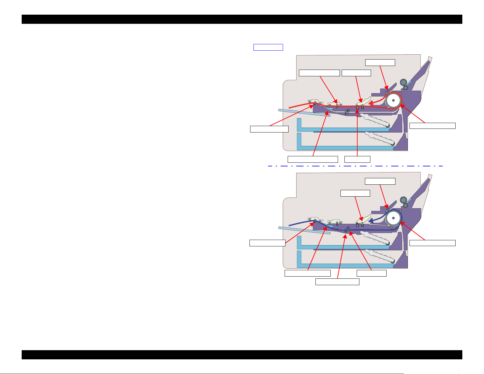
1.3.1.1.3 Paper Loading Path When Using Duplex Printing
This product has two paper turn-over paths to improve throughput when
implementing duplex printing.
After printing the front of the page, the printer holds the paper using the EJ
Roller Center/EJ Roller Front and Star Wheel Holder Assy in order to dry the
ink on the page.
After the prescribed drying time has passed, and after conveying the paper up
to a state in which it is gripped only by the EJ Roller Front and the Star Wheel
Holder Assy, the path is switched using the Change Flap.
Upper Path
After lowering the Change Flap and switching the turn-over path to the upper
path, rotate the EJ Roller Front in reverse to convey the paper with the EJ
Roller Center and PF Roller. After the paper reaches the Intermediate Roller
and the PE3 Sensor detects the leading edge of the back side of the paper, the
paper is conveyed up to the PE1 Sensor after deskewing and the back side of
the paper is printed.
Lower Path
After raising the Change Flap and switching the turn-over path to the lower
path, the printer conveys the paper using the Lower Path Roller. After the paper
reaches the Intermediate Roller via the PE2 Sensor, and the leading edge of the
back side of the paper is detected by the PE3 Sensor, the paper is conveyed up
to the PE1 Sensor after deskewing and the back side of the paper is printed.
Operating Principles Paper Loading/Feed Mechanism Operating Principles 26
Figure 1-18. Paper Turn-over Path When Implementing Duplex Printing
Confidential
Page 27
EPSON WF-7820 Series, WF-7830 Series, WF-7840 Series/EC-C7000 Revision A
EJ Roller Center
RASF Motor
*1
PF Roller
PF Motor
Paper Back Lever
*1
Hopper
*1
LD Roller
*1
ASF Motor A
Pickup Roller 1st
EJ Roller Front
Lower Path Roller
Intermediate Roller
Note "*1" : Except for WF-7830 Series
"*2": Except for WF-7820 Series
Pickup Roller 2nd
*2
1.3.2 Operating Principles
1.3.2.1 Driving Path
In this section, driving path from each motor*1 driving paper loading/feed
mechanism to rollers which load/feed paper.
Drive targets Driving motor Ref.
Pickup Roller ASF Motor p.28
Intermediate Roller ASF Motor p.29
LD Roller*/Paper Back Lever*/Hopper* RASF Motor* p.30
PF Roller/EJ Roller Center PF Motor p.31
EJ Roller Front/Lower Path Roller PF Motor p.31
Note "* " : Except for WF-7830 Series
*1. Each motor is controlled by rotary encoder.
Operating Principles Paper Loading/Feed Mechanism Operating Principles 27
Figure 1-19. Driving Path
Confidential
Page 28
EPSON WF-7820 Series, WF-7830 Series, WF-7840 Series/EC-C7000 Revision A
Pinion gear of ASF Motor
Combination gear 10.8-20.36
Combination gear 34.2-20.8-20.8
Oneway clutch
Sun gear
Planet gear (x3)
External gear
Spur Gear 24.1 (Change Slider)
Pickup Drive Shaft Pickup Drive Shaft
Pickup Roller Assy
(Paper Cassette 1st)
Oneway clutch
Sun gear
Planet gear (x3)
External gear
Spur Gear 24.1
Spur Gear 32.8.2
Pickup Roller Assy
(Paper Cassette 2nd)
Drive force transmitted only when
the Change Slider is at the 2nd ASF
Trigger ON position
Except for WF-7820 Series
Spur gear 24.1
(Change Slider)
Pickup Roller Assy
(Paper Cassette 2nd)*
Pickup Roller Assy
(Paper Cassette 1st)
Oneway
clutch
Spur gear
32.8.2
Spur gear
24.1
ASF
Motor
Oneway
clutch
Combination gear
34.2-20.8-20.8
Combination
gear 10.8-20.36
Pickup Drive Shaft
Spur
gear 24.1
Spur gear 24.1
(Change Slider)
Front
The Change Slider is at the 2nd
ASF Trigger Off position so
drive force is not transmitted to
the Pickup Roller Assy of Paper
Cassette 2nd.
The Change Slider is at the
2nd ASF Trigger On position
so drive force is transmitted to
the Pickup Roller Assy of
Paper Cassette 2nd.
Note " *" : Except for WF-7820 Series
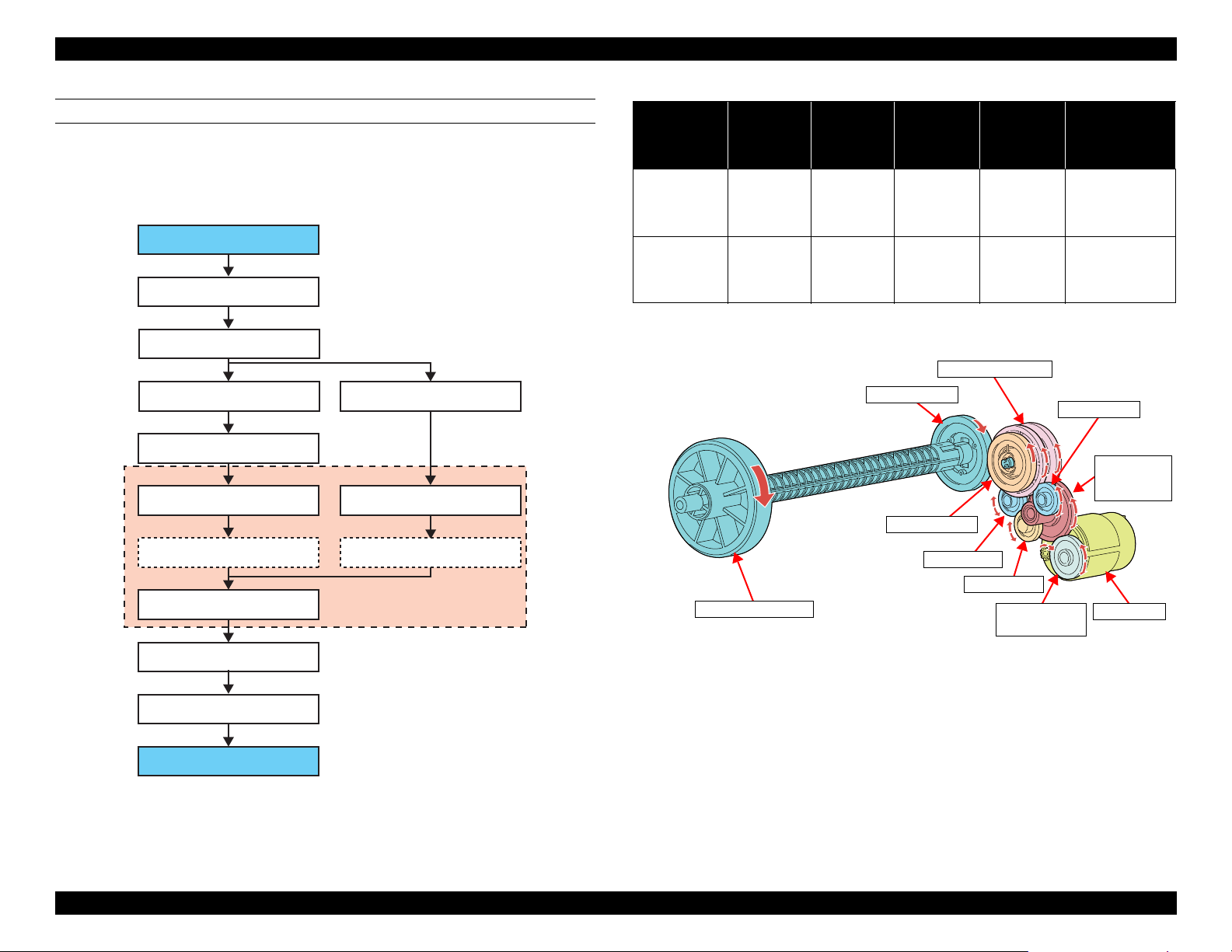
DRIVE PATH FROM ASF MOTOR TO PICKUP ROLLER
Drive force of the ASF Motor is transmitted to the Pickup Roller Assy of Paper
*1
Cassette 1st or Paper Cassette 2nd
through the path shown below.
Whether drive force is transmitted to the Pickup Roller Assy of either Paper
Cassette 1st and Paper Cassette 2nd, is controlled by the Change Slider position
and the rotation direction of the ASF Motor.
ASF Motor rotation direction Change Slider position Driving Pickup Roller Assy
CCW --- Paper Cassette 1st
CW 2nd ASF trigger ON position Paper Cassette 2nd
The Change Slider switches position depending on the action of the CR Unit.
*2
Also, the oneway clutch
controls so that the Pickup Roller rotates only in the
paper-loading direction.
Figure 1-20. Drive Path From ASF Motor to Pickup Roller (1)
*1. Except for WF-7820 Series
Operating Principles Paper Loading/Feed Mechanism Operating Principles 28
Figure 1-21. Drive Path From ASF Motor to Pickup Roller (2)
*2. See " Principle of Oneway Clutch" (p 33).
Confidential
Page 29
EPSON WF-7820 Series, WF-7830 Series, WF-7840 Series/EC-C7000 Revision A
Pinion gear of ASF Motor
Combination gear 10.8-20.36
Combination gear 29.29-10.5
Dual oneway clutch
External gear A (Full side)
Intermediate Roller
Sun gear/Output shaft
Planet gear (x5)
Planet gear (x5)
External gear B (Home side)
Spur gear 26.4
Dual drive gear
Planet gear A
Planet gear A
Planet gear A
Spur gear 26.4
Intermediate Roller
Dual oneway clutch
Combination
gear 10.8-20.36
ASF Motor
Combination
gear 29.29-
10.5
Planet gear A
Dual drive gear
Planet gear A
Planet gear A
DRIVE PATH FROM ASF MOTOR TO INTERMEDIATE ROLLER
Drive path from ASF Motor to Intermediate Roller is as shown below.
The Intermediate Roller rotates in a constant direction (paper feed direction)
with the dual oneway clutch regardless of the rotation direction of the ASF
Motor.(p 33)
Rotation
direction of ASF
Motor*
CCW CCW CW Idle
CW CW CCW
Rotation
direction of
external gear
A*
Rotation
direction of
external gear
B*
State of planet
gear B
Engaging
with the
External gear
A claw
Note " * ": Rotation direction seen form spur gear 26.4 side.
State of planet
gear C
Engaging
with the
External gear
B claw
Idle CW
Rotation direction
of sun gear/output
shaft, spur gear
26.4*
CW
Figure 1-22. Drive Path From ASF Motor to Intermediate Roller (1)
Operating Principles Paper Loading/Feed Mechanism Operating Principles 29
Figure 1-23. Drive Path From ASF Motor to Intermediate Roller (2)
Confidential
Page 30
EPSON WF-7820 Series, WF-7830 Series, WF-7840 Series/EC-C7000 Revision A
Worm gear of RASF
Motor
Combination gear A
Spur gear 17.5
Spur gear 27.2
LD Roller
Clutch
Paper Back Lever
Hopper
Hopper Cam
Combination gear B
Spur gear 1
Spur gear LD
Spur gear 1
Spur gear 2
PB Cam
Engage
clutch
LD Roller
Hopper
LD Phase Sensor
PB Cam
RASF Motor
Spur gear
Retard roller
Combination
gear A
Spur gear
17.5
Combination
gear B
Spur gear
27.2
Spur gear 1
Spur gear LD
Hopper Cam
Spur gear 1
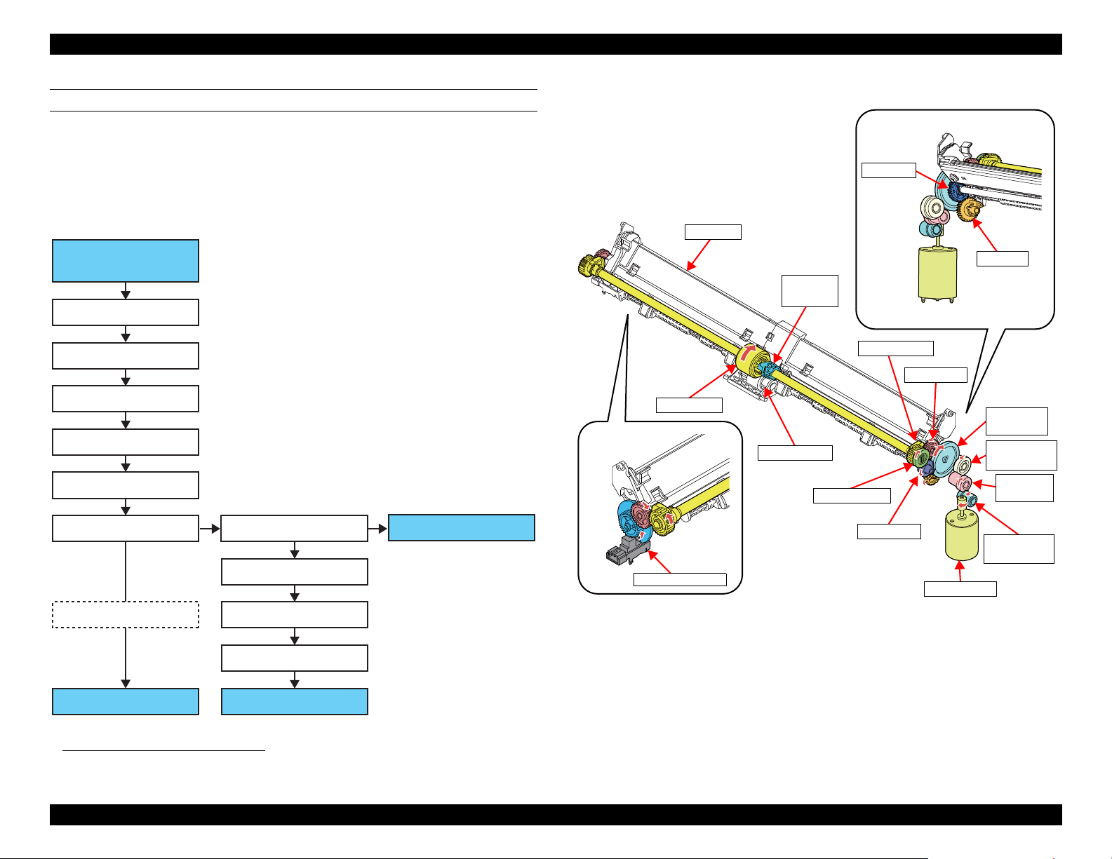
DRIVE PATH FROM RASF MOTOR TO LD ROLLER
*1
RASF Motor drives LD Roller, Hopper, and Paper Back Lever when loading paper
from rear. When the RASF Motor is rotated in the CW direction when looking from
the Output Shaft side, the engaging clutch is connected, so drive force from the
RASF Motor is transmitted up to the LD Roller. When the RASF Motor is rotated
in the CW direction, the engaging clutch is disconnected, so LD Roller does not
rotate. The state of the LD Roller is detected by the LD Phase Sensor.
Figure 1-24. Drive Path From RASF Motor to LD Roller (1)
*1. Except for WF-7830 Series
Operating Principles Paper Loading/Feed Mechanism Operating Principles 30
Figure 1-25. Drive Path From RASF Motor to LD Roller (2)
Confidential
Page 31

EPSON WF-7820 Series, WF-7830 Series, WF-7840 Series/EC-C7000 Revision A
PF Motor
EJ Roller Center
PF Pulley
PF Encoder
PF Timing Belt
PF Scale
Full side
EJ1 Pulley
PF Roller
EJ1 Pulley*
Combination gear 16-15.92
Spur gear EJ2/ EJ Roller
Front/ Spur gear 10.8
Spur gear 15.6
Flap Change Lever
Flap
Sun gear
Planet gear (x5) Planet gear (x5)
External gear A
(Home side)
External gear B
(Full side)
Dual oneway clutch
Spur gear 15.6
Spur gear 15.6
Spur gear 10.8/
Lower Path Roller
Note "*": See " Drive Path From PF Motor to PF Roller/EJ
Roller" (p 31) for details on the drive path up to
the EJ1 Pulley.
DRIVE PATH FROM PF MOTOR TO PF ROLLER/EJ ROLLER
Driving force of the PF Motor is transmitted to the PF Roller and EJ Roller
Center via PF Timing Belt.
PF Motor is controlled by reading the PF Scale Attached on the PF Pulley with
the PF Encoder.
Also, the EJ Roller Front and Lower carrying roller are also driven by the PF
Motor.
DRIVE PATH FROM EJ ROLLER FRONT/LOWER PATH ROLLER
When implementing the paper turn-over operation for duplex printing, the EJ
Roller Front and the Lower Path Roller play a role in pulling the paper into the
lower path.
EJ Roller Front and Lower Carrying Roller are rotated using the drive force of
the PF Motor. The drive force of the PF Motor is transmitted with the following
paths via the EJ1 Pulley.
Figure 1-26. Drive Path From PF Motor to PF Roller/EJ Roller
Operating Principles Paper Loading/Feed Mechanism Operating Principles 31
Figure 1-27. Drive Path From EJ Roller Front/Lower Path Roller (3)
Confidential
Page 32

EPSON WF-7820 Series, WF-7830 Series, WF-7840 Series/EC-C7000 Revision A
Spur gear EJ2
Dual oneway clutch
Combination
gear 16-15.92
EJ Roller Front
Flap
Lower Path Roller
PF Roller
EJ Roller Center
Spur gear
10.8
Spur gear 15.6
EJ2 Timing Belt
EJ1 Pulley
When the EJ Roller Front rotates in the direction to pull in the paper, the flap is
opened by the Flap Change Lever and the paper is pulled into the lower path.
When the EJ Roller Front rotates in the paper-eject direction, the Flap is closed
by the Flap Change Lever.
The Lower Path Roller rotates in the direction only when the EJ Roller Front
pulls the paper toward the Intermediate Roller, with the dual oneway clutch (p
33).
Figure 1-28. Drive Path From EJ Roller Front/Lower Path Roller (4)
Operating Principles Paper Loading/Feed Mechanism Operating Principles 32
Confidential
Page 33

EPSON WF-7820 Series, WF-7830 Series, WF-7840 Series/EC-C7000 Revision A
Planet gear
External gear
Sun gear
External gear rotates clockwise
when viewed from the full side
External gear rotates counter clockwise
when viewed from the full side
External gear
Sun gear
External gear A
Sun gear/Output shaft
Spur gear 26.4
Planet gear (x5)
External gear B
Planet gear (x5)
Dual oneway clutch used to drive
Middle Roller
Dual oneway clutch used to drive
Lower Path Roller
External gear A
Planet gear (x5)
Planet gear (x5)
Sun gear
External gear B
PRINCIPLE OF ONEWAY CLUTCH
A oneway clutch comprises an external gear, a sun gear, and three planet gears.
Rotation of the planet gear controls the drive of the sun gear.
If the external gear rotates clockwise when viewed from the full side
The teeth of the planet gears catch on the external gear ratchet, meaning that
the sun gear rotates together with the external gear.
If the external gear rotates counter clockwise when viewed from the full side
The planet gears are not fixed, therefore the planet gears rotate freely
around the sun gear together with the external gear. Accordingly, the sun
gear does not rotate.
The operating principle is also the same for the dual oneway clutch. This is
composed to include two sets: a Planet gear and an External gear on one Sun
gear.
Figure 1-30. Dual Oneway Clutch
Figure 1-29. Principle of Oneway Clutch
Operating Principles Paper Loading/Feed Mechanism Operating Principles 33
Confidential
Page 34

EPSON WF-7820 Series, WF-7830 Series, WF-7840 Series/EC-C7000 Revision A
Rear paper loading
Front paper loading
Movement of paper during printing
Movement of paper pre-paper loaded
PE3 Sensor
PE3 Sensor
1.3.2.2 Pre-paper Loading
This product uses a separate motor for paper conveyance and paper-loading
operations while printing, so paper conveyance and paper-loading operations
can be implemented independently.
The feature for loading paper without waiting for printing to end when
continuously printing, using this characteristic, is called “Pre-paper loading.”
This product supports both front paper loading (from Paper Cassette 1st and
*1
Paper Cassette 2nd
After the trailing edge of the paper being printed passes through the PE3
Sensor and the prescribed step paper feed is implemented, the next sheet is fed
up to the position where it is detected by the PE3 Sensor.
) and rear paper loading (rear ASF*2).
*1. Except for WF-7820 Series
*2. Except for WF-7830 Series
Figure 1-31. Pre-paper Loading
Operating Principles Paper Loading/Feed Mechanism Operating Principles 34
Confidential
Page 35

EPSON WF-7820 Series, WF-7830 Series, WF-7840 Series/EC-C7000 Revision A
STK Motor
STK EncoderSTK Scale
Stacker drive gear
Stacker Support
Auto Stacker
Open Unit
Stacker A4 Position Sensor
Stacker A3 Position Sensor
Stacker
Groove of Stacker
1.3.2.3 Stacker Auto Open/Close Mechanism
The Stacker Auto Open/Close Mechanism has been adopted for this product. If
the Stacker is not in an open state when starting printing, the Stacker will open
automatically in two stages according to paper size. Also, when the power
supply is turned off and the Stacker is in an open state, the Stacker will
automatically close.
The Stacker Auto Open/Close Mechanism is operated using the drive force of
the STK Motor. It is controlled by the STK Encoder.
The state of the Stacker is detected by the Stacker A4 Position Sensor and the
Stacker A3 Position Sensor Lever being ON/OFF in the Stacker groove, when
the Stacker moves.
Table 1-4. Stacker State
Stacker 1st Stage Extension
(For Paper Sizes up to A4)
Stacker 2nd Stage Extension
(For Paper Sizes Exceeding A4)
Stacker state
Stacker Housing Close Close OFF OFF
Stacker
State Sensor
Stacker
Support
Close Open OFF ON
Open Open ON ON
Also, it is possible to turn this function on and off using the panel.
Stacker A3
position
Stacker A4
position
Figure 1-32. Stacker Auto Open/Close Mechanism
Operating Principles Paper Loading/Feed Mechanism Operating Principles 35
Confidential
Page 36

EPSON WF-7820 Series, WF-7830 Series, WF-7840 Series/EC-C7000 Revision A
Pinion gear of STK
Motor
Combination gear A
Spur gear 1
Combination gear 28.10
Stacker planet gear
Planet gear Planet gear
Combination gear B
Combination gear C
Stacker drive gear
<Neutral>
Pinion gear of
STK Motor
Stacker
drive gear
Stacker planet gear
Combination
gear C
Combination gear A
Spur gear 1
Combination gear B
Top
<Stacker open> <Stacker close>
Stacker
STK Scale
Stacker drive gear
STK Encoder
STK Motor
DRIVE PATH
Drive path from the STK Motor to Stacker drive gear is as shown below.
Figure 1-33. Drive Path (1)
The Stacker Planet Gear is incorporated into the drive system path of the
Stacker Auto Open/Close Mechanism. This is to create a neutral state in
addition to the Stacker open/Stacker close states.
In addition to automatically opening and closing the Stacker with this function,
the user can also manually open or close the Stacker.
At that time, if the gear train from the STK Motor is in an engaged state, there
will be some resistance if the user tries to open or close the Stacker manually.
To avoid that, rotate the STK Motor slightly in the reverse direction after using
the Stacker auto open/close operation to disengage the planet gears and operate
it when in the neutral state.
Figure 1-34. Drive Path (2)
Operating Principles Paper Loading/Feed Mechanism Operating Principles 36
Confidential
Page 37

EPSON WF-7820 Series, WF-7830 Series, WF-7840 Series/EC-C7000 Revision A
Capping
mechanism
Maintenance Box
(Waste Ink Pad)
Pump
mechanism
Valve mechanism
Wiper mechanism
Carriage lock mechanism
Ink cartridge
Printhead
Cap
Wiper
Carriage lock lever
Pump Unit
Venting valve
Pump drive combination gear
Pump Motor
Pump Encoder
1.4 Ink System Mechanism
1.4.1 Overview
1.4.1.1 Mechanical Configuration
The ink system mechanism of this product employs the direct acting type*1 and
consists of the carriage lock mechanism, wiper mechanism, capping mechanism, pump mechanism, and venting valve (valve mechanism).
All the mechanisms are driven by the Pump Motor. The drive force of the
Pump Motor is transmitted to each mechanism via transmission parts, such as
the Pump drive combination gear, clutch gear, intermittent gear, cam, and drive
lever.
Additionally, a Maintenance Box (Waste Ink Pad) that retains waste ink from
the Cap which users can replace ink themselves is utilized.
Figure 1-35. Inksystem Mechanism (Simplified Model)
*1. There are two types of the capping: direct acting type and sliding type. In the direct acting type, the cap moves up and
down independently of the carriage and caps the printhead. In the sliding type, the printhead is capped (the cap is
moved up) when the carriage pushes the cap slider.
Figure 1-36. Ink System Mechanism
Operating Principles Ink System Mechanism 37
Confidential
Page 38

EPSON WF-7820 Series, WF-7830 Series, WF-7840 Series/EC-C7000 Revision A
Maintenance Box
Maintenance Box CSIC
Ink system
Waste Ink Pad for
borderless printing
1.4.1.2 Cleaning
Clogging of nozzles on the printhead occurs due to air bubbles generated inside
the ink path of the printhead, or an increase in ink viscosity caused by drying of
ink. To prevent the clogging or clean the clogged nozzles, various types of
cleaning (CL) are performed at different times as described in the table below.
Initial ink charge To fill the head with
Timer cleaning (TCL)
Manual
cleaning
(MCL)
Regular cap suction To prevent ink leakage
Flushing To prevent ink inside
*1. To save ink, the time between the timer cleanings is becoming longer on the most newer printers. This is achieved by
*2. When carrying out manual cleaning, CL1 → CL2 → CL3 are automatically selected and performed in order. How-
*3. “Main suction” is a suction operation that sucks up ink from cartridges to the printhead, and at the same time, sucks
*4. “Wiping” removes ink attached to the printhead nozzle surface.
*5. “Cap suction” is a suction operation that sucks ink out of the cap.
*6. “Small amount suction” is a suction operation performed to eject tiny air bubbles from the printhead. Ink amount
*7. Some off-carriage type printers use a choke valve mechanism to perform the cleaning.
Table 1-5. Printhead Cleanings
CL Type Purpose Explanation
Performed after the printer is
ink
*1
To eject bigger air
bubbles
inside the printhead
CL1 To restore a proper
convex meniscus of ink
*2
at the tip of nozzles
CL2 To eject air bubbles
inside the printhead
*7
CL3
To eject air bubbles
inside the ink supply
nozzles
from the cap
nonused nozzles from
increasing its viscosity
adopting the plastic that have the function to suppress the growth of air bubbles inside the printhead and by improving
in shape of the ink supply nozzles.
ever, in the following conditions, they may not be carried out in this order.
(Ex.) . CL3 may change to CL2 depending on the ink cartridge remaining quantity and conditions of maintenance
counter and others.
If the interval between cleaning is more than a specified period, then this may not be counted as continuous.
out air bubbles inside the printhead and thick ink inside the nozzles.
sucked by this operation is less than that by the “Main suction”.
powered at the first time.
Performed according to the printing
time and time elapsed since the last
cleaning.
Main suction*3 (short) → Wiping*4
→ Cap suction*5 → Small amount
suction*6 → Cap Suction
Main suction (middle) → Wiping →
Cap suction → Small amount suction
→ Cap Suction
Main suction (long) → Wiping → Cap
suction → Small amount suction → Cap
Suction
Sucks out ink pooling inside the cap due
to head flushing operations or the like.
The printhead is controlled to fire ink
droplets from the nozzles
periodically.
1.4.1.3 Controlling Waste Ink
Ink used by cleanings (waste ink) is absorbed by the Waste Ink Pad. If the
absorbed amount exceeds the limit of the Waste Ink Pad, leakage of the waste
ink can occur. To prevent this, the printer firmware has a counter to counts the
waste ink amount taking evaporation into account, The count value is retained
in the Maintenance Box CSIC and in the EEPROM.
Another waste ink produced by borderless printing is absorbed by absorbers
attached on the Front Paper Guide. For the borderless printing, the printer
makes an image slightly expand all the way to the edge of the paper, therefore,
the image edge portions not printed on paper must be absorbed. Some printers
also have the counter for this waste ink amount.
If a counter reaches its limit, a maintenance error occurs and replacement of the
maintenance box will be required.
Figure 1-37. Position of Waste Ink Pad
Operating Principles Ink System Mechanism 38
Confidential
Page 39

EPSON WF-7820 Series, WF-7830 Series, WF-7840 Series/EC-C7000 Revision A
A
B
C
D
E
Pump Motor
I
H
F
G
J
K
L
E
G
Drive
Drive
disengaged
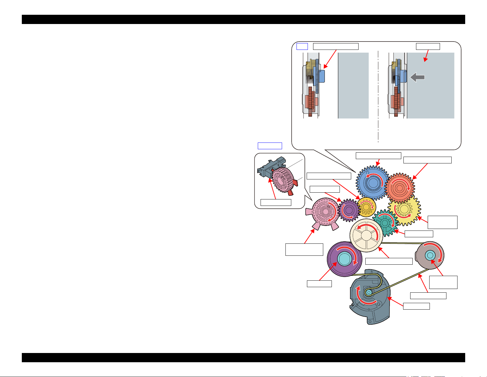
1.4.2 Operating Principles
1.4.2.1 Drive Path
The ink system mechanism is driven by the Pump Motor. The relationship
between the pump motor rotational direction and operation of each part is as
follows.
Table 1-6. Pump motor rotational direction and operation of the inksystem
Mechanism
Rotational direction of the pump motor
CW CCW
Wiper Wiping position Passing
Cap Drop Rise (capping)
Pump Release Suction
CR lock Drop (CR lock release) Rise (CR lock set)
Venting valve Open Close
*1. Rotational direction seen from output shaft
*1
Driving path is as follow.
Symbol Parts name Symbol Parts name
A Combination gear A G Intermittent gear 1
B Combination gear B
(with Pump Encoder Scale)
C Spur gear I Wiper/cap-drive cam
D Pump drive combination gear J Wiper gear 1
E Combination gear C K Wiper gear 2
F Clutch L Wiper gear 3
H Intermittent gear 2
Figure 1-38. Inksystem Mechanism Drive Path (1)
Operating Principles Ink System Mechanism 39
Confidential
Page 40

EPSON WF-7820 Series, WF-7830 Series, WF-7840 Series/EC-C7000 Revision A
Wiper gear 1
Wiper gear 2
Wiper gear 3
Intermittent
gear 1
Intermittent
gear 2
Pump drive
combination gear
Cap (p 41)
Pump (p 41)
Pump Motor
Combination
gear A
Spur gear
Combination
gear C
Clutch
Wiper/cap-drive
cam
CR lock lever (p 43)
Valve (p 44)
Wiper (p 43)
Combination
gear B
The clutch, intermittent gear 1, intermittent gear 2, and wiper/cap-drive cam move
linked to the rotation of combination gear C, but if the wiper moves to the wiping
position, the intermittent gear 2 teeth surface separate, and the combination gear C
drive is disengaged. At these times, the wiper, cap, valve, and CR lock lever will
not operate even if the pump motor is rotating. If the pump motor rotates in the
opposite direction, then the intermittent gear 2 and combination gear C will again
mesh, operating each part.
This prevents mechanisms except the pump mechanism from driving while the
pump motor rotates continuously to drive the pump mechanism.
Figure 1-39. Inksystem Mechanism Drive Path (2)
Operating Principles Ink System Mechanism 40
Confidential
Page 41

EPSON WF-7820 Series, WF-7830 Series, WF-7840 Series/EC-C7000 Revision A
Pump motor counter-clock wise
rotation (suction)
Rotates flattening
the tube.
Rotates without
flattening the tube.
Pump motor clock wise rotation (release)
Pump-drive
compound gear
Timing plate
Pump pulley Pump cam
Pump frame
Pump spring (x2)
Pump tube
Pump spacer
Pump shaft
Pump Pulley
Pump cam
Pump frame
Pump tube
Pump shaft
1.4.3 Operation of Each Mechanism
1.4.3.1 Pump Mechanism
The pump mechanism sucks ink from the printhead at cleaning.
The drive force from the pump-drive compound gear is transmitted to the pump
shaft via the timing plate. This timing plate allows the pump-drive compound
gear to start rotating at the different timing from the pump shaft. After the PF
motor rotates for a while, the pump unit starts its operation.
When the pump motor rotates counter-clock wise as seen from the output-shaft
side of the motor, the drive force via the pump-drive compound gear rotates the
pump pulley to flatten the tube to suck the air (to generate negative pressure)
inside the tube. When the pump motor rotates clock wise, the pump pulley does
not flatten the tube, and the negative pressure is released.
Figure 1-40. Pump Mechanism (1)
Operating Principles Ink System Mechanism 41
Figure 1-41. Structure of the pump unit
Confidential
Page 42

EPSON WF-7820 Series, WF-7830 Series, WF-7840 Series/EC-C7000 Revision A
Printhead
Intermittent
gear2
Cap
Tab
Cap
Printhead
Wiper/cap-drive
cam
Cap drive lever
The cam surface (in red) of
the wiper/cap-drive cam raises
and lowers the cap drive lever.
Cap
Wiper/cap-drive
cam
Cap drive lever
1.4.3.2 Cap Mechanism
The direct acting type is employed in the capping mechanism, where the cap is
moved up and down by the pump motor and the printhead is capped at the suction for cleaning.
Intermittent gear 2 rotates on drive power from the pump motor, and the cam
surface on the intermittent gear 2 pushes the cap, moving it forward. At this
time, the cap tab contacts the printhead surface, guiding the printhead on the
cap. Next, the wiper/cap-drive cam moves the cap drive lever, raising the cap,
capping the printhead.
Operating Principles Ink System Mechanism 42
Figure 1-42. Cap Mechanism (1)
Figure 1-43. Cap Mechanism (2)
Confidential
Page 43

EPSON WF-7820 Series, WF-7830 Series, WF-7840 Series/EC-C7000 Revision A
Carriage lock
Carriage lock drive lever
Lever down
(Unlock)
Lever up
(Lock)
Printhead
Compression spring
Cap drive lever
Wiper/cap-drive
cam
Printhead
Wiper
Wiper/cap-drive
cam
Wiper gear 1
Wiper gear 2
Wiper gear 3
Passing status
Wiping
Back
1.4.3.3 Carriage Lock Mechanism
The tension of the compression spring at the bottom of the carriage lock moves
up the carriage lock. When the carriage lock drive lever pushes the carriage
lock downward, the carriage lock is released.
Since the carriage lock drive lever moves up and down together with the cap
drive lever, the carriage lock also operates together with the movement of the
cap. This means that the printhead nozzle surface is always capped when the
carriage lock is set.
1.4.3.4 Wiper Mechanism
The rotation of the wiper/cap-drive cam drives the wiper mechanism. After
release, if the wiper cam rotates, the drive is conveyed to wiper gears 1, 2, and 3,
and the wiper moves along the CR unit path.
Figure 1-45. Wiper Mechanism
Figure 1-44. Carriage Lock Mechanism
Operating Principles Ink System Mechanism 43
Confidential
Page 44

EPSON WF-7820 Series, WF-7830 Series, WF-7840 Series/EC-C7000 Revision A
Pump tube (to cap)
Valve: Closed
Shaft
Valve lever
Valve: Open (vented)
Compression spring
Wiper/cap-drive cam
Link lever
The rotation of the wiper/cap
drive cam moves the salient of
the wiper drive lever along
the cam surface of the wiper/
cap drive cam (red part) to
move the valve open and close.
Wiper/cap-drive cam
(Home side)
1.4.3.5 Venting Valve
Before capping, the valve lever interferes with the link lever, therefore the
venting valve opens.
During the capping sequence, the valve lever shaft moves along the wiper/capdrive cam slot, and the valve lever drops backwards. When this happens, the
valve lever and link lever interference is removed, and the return force of the
compression spring makes this slide to the full side, closing the venting valve.
Figure 1-46. Venting Valve
Operating Principles Ink System Mechanism 44
Confidential
Page 45

TROUBLESHOOTING
CHAPTER
2
Confidential
Page 46

EPSON WF-7820 Series, WF-7830 Series, WF-7840 Series/EC-C7000 Revision A
Print check pattern
5
What is returned reason?
2
Standby condition
3
Is printing operation
finished without trouble?
Start
Turn on the printer
1
4
(p 47)
(p 47)
(p 47)
(p 48)
(p 48)
Copy an image
*: In case of “Not Trouble Found”, check fatal error code.
6
(p 48)
ADF/Scanner unit failure
Printer failure only
Yes
No
Yes
No
Yes
Yes
No
Yes
Yes
No
No
No
No
Yes
Does printer turn on
the power?
Is Power-on sequence
finished without error?
Is printing operation
finished without error?
Is ADF operation finished
without trouble?
ADF failure?
Finish
*
Is scanning operation
finished without
trouble?
A
A
A
Copy an image by ADF
2.1 Troubleshooting
This section describes the troubleshooting workflow and fatal error
information.
2.1.1 Troubleshooting Workflow
The following page describes the troubleshooting workflow. Follow the flow
when troubleshooting problems.
This flowchart is compiled based on the following
contents.
• Our experience regarding the quality problem
• ESK’s repair data
• Printer Mechanism specification for WF-7820 Series/
WF-7830 Series/WF-7840 Series/EC-C7000
If the reason for the return is evident, first check the
phenomenon user claims recurs, then proceed to the
troubleshooting.
Flowchart 2-1. Troubleshooting Workflow (1)
Troubleshooting Troubleshooting 46
Confidential
Page 47

EPSON WF-7820 Series, WF-7830 Series, WF-7840 Series/EC-C7000 Revision A
The power-on
1
sequence does
not start (p 46)
No Power
[Presumable Cause]
• PS Unit damage
• Main Board damage
• Panel Assy damage
[Major Troubleshooting]
• PS Unit replacement
• Main Board
replacement
• Panel Assy replacement
*
*: If the printer can turn on but turns off right
away, the protection circuit may cut off the
power due to an error such as a circuit
failure.
Fatal error
Please refer to " 2.3 Fatal Error
Code List (p50)" for
troubleshooting.
Error is indicated during
2
power-on sequence (p 46)
[Occurrence Condition]
This error occurs when
maintenance counter in
EEPROM exceeds the specified
value.
[Major Occurrence Timing]
• Power-on timing
• Print start timing
• Paper eject timing
• Cleaning timing
[Major Troubleshooting]
• Replace Maintenance Box
• Paper Guide Lower Porous
• Maintenance counter reset
Maintenance error
Pad replacement
(only Paper Guide Lower
Porous Pad)
No Maintenance Box error
[Occurrence Condition]
This error occurs when
Maintenance Box is not installed.
[Major Occurrence Timing]
• At power-on
• Maintenance Box monitoring
timing
[Major Troubleshooting]
Install the Maintenance Box.
Maintenance Box detection
[Occurrence Condition]
This error occurs when
Maintenance Box data is incorrect
or it is not recognized correctly.
[Major Occurrence Timing]
• Power-on timing
• Maintenance Box replacement
• Maintenance Box monitoring
[Major Troubleshooting]
• Remove and reinstall
• Maintenance Box replacement
• Holder Connector CSIC
• Holder Connector FFC
• Main Board replacement
error
timing
timing
Maintenance Box
replacement
replacement
Ink End error
[Occurrence Condition]
This error occurs when the value
of ink counter is near to the end.
[Major Occurrence Timing]
• Power-on timing
• Print start timing
• Print timing
• Cleaning timing
• Ink cartridge replacement
timing
[Major Troubleshooting]
Ink cartridge replacement
[NOTE]
If an error occurs during
printing, the page where the error
occurred is skipped and the
printing resumes from the next
page.
Ink cartridge detection error
[Occurrence Condition]
This error occurs when Ink
cartridge data is incorrect or Ink
cartridge is not recognized
correctly.
[Major Occurrence Timing]
• Power-on timing
• Print start timing
• Cleaning timing
• Ink cartridge replacement timing
[Major Troubleshooting]
• Remove and reinstall Ink
cartridge.
• Ink cartridge replacement
• CSIC Terminal replacement
• CR Contact Module
replacement
• Head FFC replacement
• Main Board replacement
No Ink cartridge error
[Occurrence Condition]
This error occurs when Ink
cartridge is not installed.
[Major Occurrence Timing]
At power-on
[Major Troubleshooting]
Install Ink cartridge.
Cover open error
[Occurrence Condition]
This error occurs when Scanner
Unit (Printer Cover) is open.
[Major Occurrence Timing]
• At power-on
• During printing
[Major Troubleshooting]
• Close Scanner Unit (Printer
Cover) replacement
• Scanner Unit (Printer Cover)
replacement
• Scanner Open Sensor
replacement
• Main Board replacement
CR Fixing Tape error
[Occurrence Condition]
This error occurs if a paper jam
occurs during the power-on
sequence before initial ink
charge.
[Major Occurrence Timing]
Power-on timing
(before initial ink charge)
[Major Troubleshooting]
Open the Scanner Unit and
remove the CR Fixing Tape.
Paper Jam error
Please refer to " Paper jam
error"
Error is indicated during printing nozzle check pattern (p 46)
3
Paper jam error
[Occurrence Condition]
This error occurs when top/bottom of
paper is not detected by PE Sensor in the
specified steps of paper feeding
operation correctly.
[Major Occurrence Timing]
• Power-on timing
• Paper loading timing
• Paper eject timing
• Duplex print timing
[Major Troubleshooting]
1 Remove the Duplex Unit, and open
the Scanner Unit (Printer Cover) and
Front Cover to remove the jammed
paper.
2 Push “Start” button.
3 If not resolved by 2), check the
following.
• Foreign material, bits of paper
• Part come-off
• PE Lever
• PE Sensor
• Float of Paper Guide Front Porous
Pad
•Main Board
• PW Sensor
[NOTE]
* If an error occurs during printing, the
page where the error occurred is skipped
and the printing resumes from the next
page.
* If an error occurs during duplex
printing, the following are performed.
• If an error occurs during the front
face of duplex printing, the page
where the error occurred and the
next page are skipped and the
printing resumes from the page
after the next.
• If an error occurs during the back
face of duplex printing, the page
where the error occurred is skipped
and the printing resumes from the
next page.
No Paper error
[Occurrence Condition]
This error occurs when top of
paper is not detected by PE Sensor
in the specified steps of paper
loading operation correctly.
[Major Occurrence Timing]
Paper loading timing
[Major Troubleshooting]
1 Put paper in Paper Cassette/
Rear ASF Unit and push
“Start” button.
2 If a paper stops before reaching
PE Sensor, remove it and
check the paper condition.
3 A) If no damage on the paper, set
edge guide correctly after
putting paper in cassette and
push “PRINT” button again.
B) If damage on the paper, check
foreign materials / parts come off / parts transformation in
paper path.
4 If not resolved by 3-A) & 3-B),
check the following.
• Pickup Roller
• Duplex Unit
• PE Sensor
• Main Board
• PF Motor
• Paper Cassette 1st
• Paper Cassette 2nd
• Rear ASF Unit
Double Feed error
[Occurrence Condition]
This error occurs on the following
cases.
• A paper is ejected without
printing during paper loading
operation.
• Actual paper length is longer
than theoretical one.
[Major Occurrence Timing]
Paper loading timing
[Major Troubleshooting]
• PE Lever replacement
• PE Sensor replacement
• PW Sensor replacement
• Main Board replacement
[NOTE]
This error occurs only for manual
duplex print.
No Paper Cassette error
[Occurrence Condition]
This error occurs if one of the
cassettes is not installed.
[Major Occurrence Timing]
Paper loading timing
(Front loading)
[Major Troubleshooting]
Install the Paper Cassette.
Paper Size Unmatch error
[Occurrence Condition]
This error occurs when actual
paper size is not matched to
theoretical one.
[Major Occurrence Timing]
• Duplex print timing
• FAX data print timing
[Major Troubleshooting]
1 Put correct sized paper in
cassette, and push “START”
button.
2 If not resolved by step 1),
check the following points.
• PE Lever
•PE Sensor
• PW Sensor
• Main Board
Flowchart 2-2. Troubleshooting Workflow (2)
Troubleshooting Troubleshooting Workflow 47
Confidential
Page 48

EPSON WF-7820 Series, WF-7830 Series, WF-7840 Series/EC-C7000 Revision A
Problems related to print result or during printing (p 46)
4
Poor Printing
[Phenomenon]
• Poor printing quality
• Ink stain on paper
• Dot missing
• Paper eject without printing
[Presumable Cause]
• Driver / Panel mis-setting
• Contamination of CR scale
• Contamination of Printhead
Cover
• Printhead damage
• Ink clogging of Printhead
• Contamination on Cap Unit /
Wiper of Inksystem Unit
• Inksystem Unit damage
• Float of Paper Guide Front
Porous Pad
• Narrow PG
• PE Lever damage
• PE Sensor damage
• PW Sensor damage
• Ink Tank Breathable Film is
moist
• Mixture of different type ink
[Major Troubleshooting]
• Driver / Panel re-setting
• CR Scale replacement
• Printhead cover cleaning
• Printhead cleaning
• Printhead replacement
• Rubber cl eaning of Cap Unit of
Inksystem Unit
• Inksystem Unit replacement
• Paper Guide Front Porous Pad
re-installation
• PG readjustment
• Printer Mechanism
replacement
• PE Lever replacement
• PE Sensor replacement
• PW Sensor replacement
• Tank Assy replacement
• Ink supply route replacement
or cleaning
Poor Paper Loading
[Presumable Cause]
• Use of 3rd party media
• Edge guide mis-setting
• Foreign material
• Part come-off
• Contamination of paper feed
roller (Duplex Unit)
• Cassette Assy damage
• Pickup Roller deterioration,
contamination
• Contamination of PF roller
[Major Troubleshooting]
• Recommendation of EPSON
media
• Edge guide re-setting
• Foreign material removal
• Part re-installation
• PF Roller replacement
• Cassette Assy replacement
• Pickup Roller replacement
Abnormal Noise
[Presumable Cause]
• Foreign material
• Insufficient grease
• Gear damage
[Major Troubleshooting]
• Foreign material removal
• Lubrication of grease
• Gear replacement
Nothing printed
[Presumable Cause]
• Ink Tank Breathable Film is
moist
• Ink Tube is twisted
• Ink Tube installation is not
enough
[Major Troubleshooting]
• Tank Assy replacement
• Ink Tube re-installation or
replacement
Scanning cannot be
performed
5
successfully (p 46)
Scanner failure
[Presumable Cause]
• Contamination of Scanner
Glass
• Contamination of Document
Pad
• CIS Unit bonding failure
• CIS Unit damage
• Scanner Motor damage
[Major Troubleshooting]
• Scanner Glass cleaning
• Document Pad cleaning
• Document Pad replacement
• CIS Unit replacement
• Scanner Motor replacement
ADF does not operate
6
normally (p 46)
ADF failure
[Phenomenon]
• No paper feed
• Double feed
• Paper jam
• Paper skew
[Presumable Cause]
• Wear of Pickup Roller
• Wear of ADF Pad Assy
•Gear damage
• ADF Motor damage
• Contamination of Scanner Glass
• ADF Document Support Assy
damage
• Foreign material
• ADF Cover Assy damage
• Wear of EJ Roller
• ADF PE Sensors damage
[Major Troubleshooting]
• ADF Cover Assy replacement
• ADF Pad Assy replacement
• Scanner Glass cleaning
• ADF Document Support Assy
replacement
• Foreign material removal
• ADF Unit replacement
Flowchart 2-3. Troubleshooting Workflow (3)
Troubleshooting Troubleshooting Workflow 48
Confidential
Page 49

EPSON WF-7820 Series, WF-7830 Series, WF-7840 Series/EC-C7000 Revision A
㻜㻝㻟㻜 㻴㻼
㻜㻝㻟㻜 㻴㻼
㻜㻝㻟㻜 㻴㻼
㻜㻝㻟㻜 㻴㻼
㻜㻝㻟㻜 㻴㻼
㻜㻝㻟㻜 㻴㻼
㻜㻝㻟㻜 㻴㻼
2.2 Power-On Sequence
This section describes the power-on sequences as reference for
troubleshooting. The preconditions are as follows.
Condition: Power-on sequence (See Table 2-1)
No error occurred when you turned on the printer last time and it has been
correctly turned off.
Initial ink charge was done and every tank has sufficient ink.
No paper on the paper path.
The Printhead is capped and the Carriage is normally fixed by the CR Lock.
Maintenance error recovery has never been performed.
Table 2-1. Normal Power-on Sequence
Operation
*1
1. Checking for waste ink overflow
1-1.Checks the maintenance counter if the waste ink overflow is
occurring.
2. Seeking the home position
2-1.The CR Unit moves to the Home side slowly and confirms it touches
the Right Frame.
2-2.By regarding the position where the CR Unit touches the Right Frame
as the specified distance from the origin, the home position is
determined. Thereafter, the position of the CR Unit is monitored
based on the information provided by the CR Encoder.
2-3.The CR Unit slowly moves to its home position.
3. APG reset
3-1.The CR Unit moves to the Full side slowly and confirms it touches the
Left Frame.
3-2.Drive the PF Motor clockwise while monitoring the APG Sensor.
CR Unit/PF Roller
movement and
position
㻯㻾㻌㼁㼚㼕㼠
Table 2-1. Normal Power-on Sequence
Operation
*1
3-4.CR Unit moves to Home side a little.
3-5.The PF Motor rotates clockwise to confirm the APG Change Gear is
disengaged from the APG Wheel Train.
4. Low temperature operation sequence
*3
4-1.The CR Unit moves to its home position.
4-2.The CR Unit moves back and forth between near the Home Position
and near the Left Frame for two times.
5. Printhead initialization
*2
㻜㻝㻟㻜
㻴㻼
㻯㻾㻌㻸㼛㼏㼗
5-1.Checks if the fuse on the Printhead circuit boards is blown.*
6. CR lock setting
4
6-1.Rotate the Pump Motor clockwise to set the CR Lock.
Note *1 : The rotation directions of the PF Motor are as follows.
Clockwise: Paper is fed normally
Counterclockwise: Paper is fed backward
*2: The conditions of the Lock CR are as follows.
Red: Lock CR is set
White: Lock CR is released
o
*3: Executed when the detected temperature is under 5
C (41oF) by the thermistor on the
Printhead.
*4: The fatal error occurs if there is a problem such as the fuse blew.
CR Unit/PF Roller
movement and
position
*2
㻜㻝㻟㻜 㻴㻼
㻜㻝㻟㻜 㻴㻼
㻜㻝㻟㻜 㻴㻼
㻜㻝㻟㻜 㻴㻼
㻜㻝㻟㻜 㻴㻼
3-3.When the APG Sensor detects the change from off to on, it checks the
number of rotation steps of the PF Motor. If it is greater than the
prescribed number of steps, it judges that it has switched from PG4 to
PG1.
Troubleshooting Power-On Sequence 49
Confidential
Page 50

EPSON WF-7820 Series, WF-7830 Series, WF-7840 Series/EC-C7000 Revision A
Printer Error
Printer error.
Turn the power off and on again.
If the problem persists, contact Epson Support.
000031
LCD display screen
Error code
2.3 Fatal Error Code List
This section describes how to check the fatal error code, description, and the
possible causes.
2.3.1 Displaying the Fatal Error Code
The fatal error code is stored in the EEPROM on the Main Board and can be
read out using the Adjustment Program. When a fatal error occurs, this product
displays the fatal error code automatically on the panel LCD.
Figure 2-1. Indication of the fatal error code
2.3.2 Fatal Error Code
This section describes the fatal error code and the possible cause for this
product.
" ADF/Scanner (p51)"
" Printer (CR) (p58)"
" Printer (PF) (p61)"
" Printer (ASF) (p63)"
" Printer (2nd ASF: WF-7830 Series/WF-7840 Series/EC-C7000 only)
(p66)"
" Printer (I/S) (p68)"
" Printer (Stacker) (p70)"
" Printer (RASF: WF-7820 Series/WF-7840 Series/EC-C7000 only) (p72)"
" Printer (Head/CSIC) (p74)"
" Printer (Others) (p76)"
" System Error (p78)"
ADF related errors are included in the scanner fatal error
list.
Troubleshooting Fatal Error Code List 50
Confidential
Page 51

EPSON WF-7820 Series, WF-7830 Series, WF-7840 Series/EC-C7000 Revision A
2.3.2.1 ADF/Scanner
Table 2-2. ADF/Scanner
Error
code
100001 ADF PID excess speed error
100002 ADF PID reverse error
100003 ADF PID lock error
Error name Possible cause Confirmation procedure Connector No.
Failed to read the ADF Encoder
1. Contamination of the ADF Scale
2. Damage or skew of the ADF Encoder FFC
3. Failure of the ADF Encoder
Failure of the ADF Motor Driver
4. Failure of the Main Board
Paper feed fails, stopped by obstacles
1. Paper feed was stopped by;
• Obstacles such as jammed paper
• Overload of the paper feed mechanism
• Disengaging or tooth breakage of wheel train of the paper feed
mechanism
Failed to read the PF Encoder
2. Jumping of the ADF Timing Belt
3. Contamination of the ADF Scale
4. Damage or skew of the ADF Encoder FFC
5. Failure of the ADF Encoder
6. Failure of the Main Board
The ADF motor did not run or obstacles exist in the paper path
1. Overload of the paper feed mechanism
2. The ADF Timing Belt become frayed, jumping, or the wheel train of
paper feed mechanism is disengaged or its tooth is broken
Failed to read the ADF Encoder
3. Contamination of the ADF Scale
4. Disconnection, break, skew or damage of the ADF Encoder FFC
5. Failure of the ADF Encoder
6. Failure of the ADF Motor (the lead wire is broken or the connector is
disconnected)
7. Failure of the Main Board
1. Clean the ADF Scale if it is contaminated.
2. Check the cable/FFC of the ADF Motor/Encoder.
3. Replace the ADF Encoder with a new one.
4. Replace the Main Board with a new one.
1. Check that no pieces of paper or foreign objects exist in the paper path.
2. Check the load of the ADF paper feed mechanism.
3. Check the ADF Drive Gear Wheel Train.
4. Clean the ADF Scale if it is contaminated.
5. Check the cable/FFC of the ADF Motor/Encoder.
6. Replace the ADF Encoder with a new one.
7. Replace the Main Board with a new one.
1. Check that no jammed paper exist in the paper path.
2. Check the load of the ADF.
3. Check the ADF Drive Gear Wheel Train.
4. Clean the ADF Scale if it is contaminated.
5. Check the cable/FFC of the ADF Motor/Encoder.
6. Replace the ADF Encoder with a new one.
7. Check the connector of the ADF Motor.
8. Replace the ADF Motor with a new one.
9. Replace the Main Board with a new one.
Main Board
•CN900
•CN202
Relay ADF
Board
•CN109
•CN105
Troubleshooting Fatal Error Code List 51
Confidential
Page 52

EPSON WF-7820 Series, WF-7830 Series, WF-7840 Series/EC-C7000 Revision A
Table 2-2. ADF/Scanner
Error
code
100005 ADF PID excess load error
100006 ADF PID driving time error
100009 ADF BS+ excess speed error
100010 ADF BS+ reverse error
Error name Possible cause Confirmation procedure Connector No.
The ADF Motor stopped running in the middle of the operation
1. The ADF was stopped by;
• Obstacles such as jammed paper
• Overload of the paper feed mechanism
• Disengaging or breakage of the gears
Failed to read the ADF Encoder
2. Jumping of the ADF Timing Belt
3. Contamination of the ADF Scale
4. Disconnection, break, skew or damage of the ADF Motor cable/encoder
FFC
5. Failure of the ADF Motor (not completely broken)
6. Failure of the Main Board
Malfunction or crash of the firmware
Failed to read the ADF Encoder
1. Contamination of the ADF Scale
2. Damage or skew of the ADF Encoder FFC
3. Failure of the ADF Encoder
Failure of the Scanner Motor Driver
4. Failure of the Main Board
Paper feed fails, stopped by obstacles
1. Paper feed was stopped by;
• Obstacles such as jammed paper
• Overload of the paper feed mechanism
• Disengaging or tooth breakage of wheel train of the paper feed
mechanism
Failed to read the ADF Encoder
2. Contamination of the ADF Scale
3. Damage or skew of the ADF Encoder FFC
4. Failure of the ADF Encoder
5. Failure of the Main Board
1. Check that no pieces of paper or foreign objects exist in the paper path.
2. Check the load of the ADF paper feed mechanism.
3. Check the ADF Drive Gear Wheel Train.
4. Check the ADF Scale for damage or contamination.
5. Check the cable/FFC of the ADF Motor/Encoder.
6. Replace the ADF Motor with a new one.
7. Replace the Main Board with a new one.
1. Turn the printer off and back it on.
2. If the error still occurs after the restart, replace the Main Board.
1. Clean the ADF Scale if it is contaminated.
2. Check the cable/FFC of the ADF Motor/Encoder.
3. Replace the ADF Encoder with a new one.
4. Replace the Main Board with a new one.
1. Check that no pieces of paper or foreign objects exist in the paper path.
2. Check the load of the ADF paper feed mechanism.
3. Check the ADF Drive Gear Wheel Train.
4. Clean the ADF Scale if it is contaminated.
5. Check the cable/FFC of the ADF Motor/Encoder.
6. Replace the ADF Encoder with a new one.
7. Replace the Main Board with a new one.
Main Board
•CN900
•CN202
Relay ADF
Board
•CN109
•CN105
---
Main Board
•CN900
•CN202
Relay ADF
Board
•CN109
•CN105
Troubleshooting Fatal Error Code List 52
Confidential
Page 53

EPSON WF-7820 Series, WF-7830 Series, WF-7840 Series/EC-C7000 Revision A
Table 2-2. ADF/Scanner
Error
code
100011 ADF BS+ lock error
100013 ADF BS+ excess load error
100014 ADF BS+ driving time error
100016 HP detection failure
Error name Possible cause Confirmation procedure Connector No.
The ADF Motor did not run
1. The ADF was stopped by;
• Obstacles such as jammed paper
• Overload of the mechanism
• Disengaging or breakage of the gears
Failed to read the ADF Encoder
2. Contamination of the ADF Scale
3. Disconnection, break, skew or damage of the ADF Motor cable/Encoder
FFC
4. Failure of the ADF Encoder
5. Failure of the ADF Motor (the lead wire is broken or the connector is
disconnected)
6. Failure of the Main Board
The ADF Motor stopped running in the middle of the operation
1. The ADF was stopped by;
• Obstacles such as jammed paper
• Overload of the paper feed mechanism
• Disengaging or tooth breakage of wheel train of the gears
Failed to read the ADF Encoder
2. Contamination of the ADF Scale
3. Failure of the ADF Motor (not completely broken)
4. Failure of the Main Board
Malfunction or crash of the firmware
The Scanner CR could not return to its home.
1. Damage or disengaging of Wheel Train of the Drive Mechanism
2. Disengaging, fraying, jumping of the Timing Belt
Failed to read the white standard/home patterns.
3. Disconnection, break, skew or damage of the Scanner FFC
4. Failure of the CIS module
5. Failure of the Scanner Housing
6. Failure of the Main Board
1. Check that no pieces of paper or foreign objects exist in the paper path.
2. Check the ADF Drive Gear Wheel Train.
3. Clean the ADF Scale if it is contaminated.
4. Check the cable/FFC of the ADF Motor/Encoder.
5. Replace the ADF Encoder with a new one.
6. Replace the ADF Motor with a new one.
7. Replace the Main Board with a new one.
1. Check that no pieces of paper or foreign objects exist in the paper path.
2. Check the load of the ADF paper feed mechanism.
3. Check the ADF Drive Gear Wheel Train.
4. Clean the ADF Scale if it is contaminated.
5. Replace the ADF Motor with a new one.
6. Replace the Main Board with a new one.
1. Turn the printer off and back it on.
2. If the error still occurs after the restart, replace the Main Board.
1. With the ADF Unit or the Document Cover opened, turn the power on.
2. Check if the CIS moves to the right to read the white standard/home patterns.
3. Check if the CIS’s emission color of the CIS is white (not greenish, reddish,
or bluish).
If the light does not look like white, check the Scanner FFC for damage,
disconnection or skew.
4. Replace the Scanner Unit with a new one.
5. Replace the Main Board with a new one.
Main Board
•CN900
•CN202
Relay ADF
Board
•CN109
•CN105
---
Main Board
•CN803
•CN912
•CN801
Troubleshooting Fatal Error Code List 53
Confidential
Page 54

EPSON WF-7820 Series, WF-7830 Series, WF-7840 Series/EC-C7000 Revision A
Table 2-2. ADF/Scanner
Error
code
100017
100018
100019
100020 Measurement error
100032 LED light failure
100054 Paper jam error
Error name Possible cause Confirmation procedure Connector No.
Contact detection distance
exceeded
Opposite side contact
detection distance exceeded
error
Wrong contact detection
distance error
The Scanner CR cannot completely reach the home (left side).
1. Damage or disengaging of Wheel Train of the Drive Mechanism
Failure of Scanner Encoder reading
2. Damage or skew of the Scanner FFC
3. Failure of the CIS Module
4. Failure of the Scanner Housing
5. Failure of the Main Board
The Scanner CR cannot completely reach the opposite side of the home
(right side)
1. Damage or disengaging of wheel train of the drive mechanism
Failed to read the Scanner Encoder
2. Damage or skew of the Scanner FFC
3. Failure of the CIS Module
4. Failure of the Scanner Housing
5. Failure of the Main Board
1. Failure of the CIS Module
2. Failure of the Scanner Housing
(Including wrong attachment of the origin mark)
3. Failure of the Main Board
4. Failure of the Scanner FFC / Connection failure of the Scanner FFC
5. Failure of the Scanner Motor / Connection failure of the Scanner Motor
Cable
Overload of the Scanner Drive Mechanism
Failure of the Scanner Motor
Failure of the CIS LED light (RGB)
1. Disconnection, break, skew or damage of the Scanner FFC
2. Failure of the CIS Module
3. Failure of the Main Board
No jammed paper is remaining but the sensor does not turn off
1. Failure of the ADF PE Sensor
2. Failure of the cable
Jammed paper is remaining
The Paper Feed Rollers and Paper Conveying Rollers slip too much
At power-on, during paper feed, during scanning
1. With the Document Cover opened, turn the power on.
2. Check if the CIS (CR) reaches (comes in contact with) the right side.
3. Check the Wheel Train of the Drive Mechanism for damage.
4. Check the Scanner FFC for damage, disconnection or skew.
5. Replace the Scanner Unit with a new one.
6. Replace the Main Board with a new one.
1. Check the connector of the Scanner Motor cable.
2. Check the cable/FFC of the Scanner Motor.
3. Replace the Scanner Unit with a new one.
4. Replace the Main Board with a new one.
1. Check if the CIS (CR) moves or not.
1. Check the Timing Belt for Damage or disengaging
2. Check the Wheel Train of the drive mechanism for damage.
2. Replace the Scanner Unit with a new one.
3. Replace the Main Board with a new one.
1. Check the color of the LED at power-on.
2. Check the Scanner FFC for damage, disconnection or skew.
3. Replace the Scanner Unit with a new one.
4. Replace the Main Board with a new one.
1. Open the PGU LD ADF Assy and check if paper exist or not.
2. Open the ADF Document Support Cover and check if paper exist or not.
3. Open the ADF and check if paper exist or not.
4. Check if the paper sensor lever moves up and down.
5. Replace the ADF unit with a new one.
6. Replace the Scanner Unit with a new one.
7. Replace the Main Board with a new one.
Main Board
•CN803
•CN912
•CN801
---
---
Main Board
•CN803
•CN912
•CN801
Main Board
•CN900
•CN202
Relay ADF
Board
•CN109
•CN103
Troubleshooting Fatal Error Code List 54
Confidential
Page 55

EPSON WF-7820 Series, WF-7830 Series, WF-7840 Series/EC-C7000 Revision A
Table 2-2. ADF/Scanner
Error
code
100065 FB PID excess speed error
100066 FB PID reverse error
100067 FB PID lock error
Error name Possible cause Confirmation procedure Connector No.
Failed to read the Scanner Encoder
1. Contamination of the Scanner Scale
2. Damage or skew of the Scanner FFC
3. Failure of the Scanner Encoder
Failure of the Scanner Motor Driver
4. Failure of the Main Board
Operation failure of the Scanner Motor
1. The scanning operation was stopped by;
• Disengaging of the Scanner CR
• Disengaging of the Scanner Motor Pulley or cracking of the Scanner
Motor Gears
Failure of Scanner Encoder reading
2. Contamination of the Scanner Encoder
3. Damage or skew of the Scanner FFC
4. Failure of the Scanner Encoder
5. Failure of the Main Board
The Scanner Motor did not run
1. The scanning operation was stopped by;
• Disengaging of the Scanner CR
• Disengaging of the Scanner Motor Pulley or cracking of the Scanner
Motor Gears
Failed to read the Scanner Encoder
2. Contamination of the Scanner Encoder
3. Damage or skew of the Scanner FFC
4. Failure of the Scanner Encoder
5. Failure of the Scanner Motor
6. Failure of the Main Board
1. Check the Scanner FFC for damage, disconnection or skew.
2. Replace the Scanner Unit with a new one.
3. Replace the Main Board with a new one.
1. Check the Scanner FFC for damage, disconnection or skew.
2. Replace the Scanner Unit with a new one.
3. Replace the Main Board with a new one.
Main Board
•CN912
•CN801
•CN803
1. Check the Scanner FFC for damage, disconnection or skew.
2. Replace the Scanner Unit with a new one.
3. Replace the Main Board with a new one.
Troubleshooting Fatal Error Code List 55
Confidential
Page 56

EPSON WF-7820 Series, WF-7830 Series, WF-7840 Series/EC-C7000 Revision A
Table 2-2. ADF/Scanner
Error
code
100068 FB PID acceleration lock error
100069 FB PID excess load error
100070 FB PID driving time error
100073 FB BS+ excess speed error
Error name Possible cause Confirmation procedure Connector No.
The Scanner Motor did not run
1. The scanning operation was stopped by;
• Disengaging of the Scanner CR
• Disengaging of the Scanner Motor Pulley or cracking of the Scanner
Motor Gears
Failed to read the Scanner Encoder
2. Contamination of the Scanner Encoder
3. Damage or skew of the Scanner FFC
4. Failure of the Scanner Encoder
5. Failure of the Scanner Motor
6. Failure of the Main Board
The Scanner Motor stopped running in the middle of the operation
1. The scanning operation was stopped by;
• Disengaging of the Scanner CR
• Disengaging of the Scanner Motor Pulley or cracking of the Scanner
Motor Gears
Failed to read the Scanner Encoder
2. Contamination of the Scanner Encoder
3. Disconnection, break, skew or damage of the Scanner FFC
4. Failure of the Scanner Encoder
5. Failure of the Scanner Motor (not completely broken).
6. Failure of the Main Board
Malfunction or crash of the firmware
Failed to read the Scanner Encoder
1. Contamination of the Scanner Scale
2. Damage or skew of the Scanner FFC
3. Failure of the Scanner Encoder
Failure of the Scanner Motor Driver
4. Failure of the Main Board
1. Check the Scanner FFC for damage, disconnection or skew.
2. Replace the Scanner Unit with a new one.
3. Replace the Main Board with a new one.
1. Check the Scanner FFC for damage, disconnection or skew.
2. Replace the Scanner Unit with a new one.
3. Replace the Main Board with a new one.
1. Turn the printer off and back it on.
2. If the error still occurs after the restart, replace the Main Board.
1. Check the Scanner FFC for damage, disconnection or skew.
2. Replace the Scanner Unit with a new one.
3. Replace the Main Board with a new one.
Main Board
•CN912
•CN801
•CN803
---
Main Board
•CN912
•CN801
•CN803
Troubleshooting Fatal Error Code List 56
Confidential
Page 57

EPSON WF-7820 Series, WF-7830 Series, WF-7840 Series/EC-C7000 Revision A
Table 2-2. ADF/Scanner
Error
code
100074 FB BS+ reverse error
100075 FB BS+ lock error
100077 FB BS+ excess load error
100078 FB BS+ driving time error
Error name Possible cause Confirmation procedure Connector No.
Operation failure of the Scanner Motor
1. The scanning operation was stopped by;
• Disengaging of the Scanner CR
• Disengaging of the Scanner Motor Pulley or cracking of the Scanner
Motor Gears
Failed to read the Scanner Encoder
2. Contamination of the Scanner Encoder
3. Damage or skew of the Scanner FFC
4. Failure of the Scanner Encoder
5. Failure of the Main Board
The Scanner Motor did not run
1. The scanning operation was stopped by;
• Disengaging of the Scanner CR
• Disengaging of the Scanner Motor Pulley or cracking of the Scanner
Motor Gears
Failed to read the Scanner Encoder
2. Contamination of the Scanner Encoder
3. Damage or skew of the Scanner FFC
4. Failure of the Scanner Encoder
5. Failure of the Scanner Motor
6. Failure of the Main Board
The Scanner Motor stopped running in the middle of the operation
1. The scanning operation was stopped by;
• Disengaging of the Scanner CR
• Disengaging of the Scanner Motor Pulley or cracking of the Scanner
Motor Gears
Failed to read the Scanner Motor encoder
2. Contamination of the Scanner Encoder
3. Damage or skew of the Scanner FFC
4. Failure of the Scanner Encoder
5. Failure of the Scanner Motor (not completely broken).
6. Failure of the Main Board
Malfunction or crash of the firmware
1. Check the Scanner FFC for damage, disconnection or skew.
2. Replace the Scanner Unit with a new one.
3. Replace the Main Board with a new one.
1. Check the Scanner FFC for damage, disconnection or skew.
2. Replace the Scanner Unit with a new one.
3. Replace the Main Board with a new one.
1. Check the Scanner FFC for damage, disconnection or skew.
2. Replace the Scanner Unit with a new one.
3. Replace the Main Board with a new one.
1. Turn the printer off and back it on.
2. If the error still occurs after the restart, replace the Main Board.
Main Board
•CN912
•CN801
•CN803
---
Troubleshooting Fatal Error Code List 57
Confidential
Page 58

EPSON WF-7820 Series, WF-7830 Series, WF-7840 Series/EC-C7000 Revision A
2.3.2.2 Printer (CR)
Table 2-3. Printer (CR)
Error
code
000020 CR PID driving time error
000021 CR PID excess load error
000022 CR PID excess speed error
000023 CR PID reverse error
Error name Possible cause Confirmation procedure Connector No.
Malfunction or crash of the firmware
The CR Motor stopped running in the middle of the operation
1. The CR was stopped by;
• Obstacles such as jammed paper
• Overload of the mechanism
• Interfere with the Inksystem Unit
• Disengaging, fraying, jumping of the Timing Belt
• Crack or disengaging of the gear, or the APG lever interferes with the CR
Failed to read the CR Encoder
2. Contamination of the CR Scale
3. Failure of the CR Motor (not completely broken)
4. Failure of the Main Board
Failed to read the CR Encoder
1. Contamination of the CR Scale
2. Damage or skew of the CR Encoder FFC
3. Failure of the CR Encoder
Failure of the CR Motor Driver
4. Failure of the Main Board
Operation failure of the CR Motor, stopped by obstacles
1. CR was stopped by;
• Obstacles such as jammed paper
• Interfere with the Inksystem Unit
• Disengaging or breakage of the gears
Failed to read the CR Encoder
2. Jumping of the CR Timing Belt
3. Contamination of the CR Scale
4. Damage or skew of the CR Encoder FFC
5. Failure of the CR Encoder
6. Failure of the Main Board
1. Turn the printer off and back it on.
2. If the error still occurs after the restart, replace the Main Board.
1. Check that no obstacle exist in the CR motion range.
2. Check the CR lock and Inksystem Unit for any abnormality.
3. Check the Timing Belt for fraying or looseness.
4. Check the load applied to the CR by moving it by hand.
5. Check if the lubricant on the CR Guide Shaft is adequate.
6. Check the CR drive mechanism.
7. Clean the CR Scale if it is contaminated.
8. Replace the CR Motor with a new one.
9. Replace the Main Board with a new one.
1. Clean the CR Scale if it is contaminated.
2. Check the FFC of the CR Encoder.
3. Replace the CR Encoder with a new one.
4. Replace the Main Board with a new one.
1. Check that no obstacle exist in the CR motion range.
2. Check the CR lock and Inksystem Unit for any abnormality.
3. Check the Timing Belt for fraying or looseness.
4. Clean the CR Scale if it is contaminated.
5. Check the CR Encoder FFC or the connector.
6. Replace the CR Encoder with a new one.
7. Replace the Main Board with a new one.
---
---
Main Board
•CN200
•CN370
Troubleshooting Fatal Error Code List 58
Confidential
Page 59

EPSON WF-7820 Series, WF-7830 Series, WF-7840 Series/EC-C7000 Revision A
Table 2-3. Printer (CR)
Error
code
000024 CR PID lock error
000025 CR PID speed fall error
000030
000031
CR load position driving time
error
CR load position excess load
error
Error name Possible cause Confirmation procedure Connector No.
The CR Motor did not run, or the CR could not move smoothly
1. Overload of the CR
Failed to read the CR Encoder
2. The Timing Belt become frayed or jumping
3. Contamination of the CR Scale
4. Disconnection, break, skew or damage of the CR Encoder FFC
5. Failure of the CR Encoder
6. Failure of the CR Motor (the lead wire is broken or the connector is
disconnected)
7. Failure of the Main Board
Operation failure of the CR
1. The CR was stopped by;
• Obstacles such as jammed paper
• Overload of the mechanism
• Interfere with the Inksystem Unit
Failed to read the CR Encoder
2. The Timing Belt become loosened or jumping
3. Contamination of the CR Scale
4. Damage or skew of the CR Encoder FFC
5. Failure of the CR Motor
6. Failure of the Main Board
Malfunction or crash of the firmware
The CR Motor stopped running in the middle of the operation
1. The CR was stopped by;
• Obstacles such as jammed paper
• Overload of the mechanism
• Interfere with the Inksystem Unit
• Disengaging or breakage of the gears
• Disengaging, fraying, jumping of the Timing Belt
Failed to read the CR Encoder
2. Contamination of the CR Scale
3. Failure of the CR Motor (not completely broken)
4. Failure of the Main Board
1. Check that no obstacle exist in the CR motion range.
2. Move the CR by hand to see if it moves smoothly without getting stuck.
3. Check the Timing Belt for fraying or looseness.
4. Clean the CR Scale if it is contaminated.
5. Check the connector and the CR Encoder FFC for damage.
6. Replace the CR Encoder FFC with a new one.
7. Check the connector of the CR Motor.
8. Replace the CR Motor with a new one.
9. Replace the Main Board with a new one.
1. Check that no obstacle exist in the CR motion range.
2. Check the CR lock and Inksystem Unit for any abnormality.
3. Check the Timing Belt for looseness.
4. Clean the CR Scale if it is contaminated.
5. Check the connector of the CR Encoder FFC.
6. Replace the CR Motor with a new one.
7. Replace the Main Board with a new one.
1. Turn the printer off and back it on.
2. If the error still occurs after the restart, replace the Main Board.
1. Check that no obstacle exist in the CR motion range.
2. Check the CR lock and Inksystem Unit for any abnormality.
3. Check the Timing Belt for fraying or looseness.
4. Check the load applied to the CR by moving it by hand.
5. Check if the lubricant on the CR Guide Shaft is adequate.
6. Check the CR drive mechanism.
7. Clean the CR Scale if it is contaminated.
8. Replace the CR Motor with a new one.
9. Replace the Main Board with a new one.
Main Board
•CN200
•CN370
---
Main Board
•CN200
•CN370
Troubleshooting Fatal Error Code List 59
Confidential
Page 60

EPSON WF-7820 Series, WF-7830 Series, WF-7840 Series/EC-C7000 Revision A
Table 2-3. Printer (CR)
Error
code
000032
000033 CR load position reverse error
CR load position excess speed
error
Error name Possible cause Confirmation procedure Connector No.
Failed to read the CR Encoder
1. Contamination of the CR Scale
2. Damage or skew of the CR Encoder FFC
3. Failure of the CR Encoder
Failure of the CR Motor driver
4. Failure of the Main Board
Operation failure of the CR Motor, stopped by obstacles
1. CR was stopped by;
• Obstacles such as jammed paper
• Overload of the mechanism
• Interfere with the Inksystem Unit
Failed to read the CR Encoder
2. Jumping of the CR Timing Belt
3. Contamination of the CR Scale
4. Damage or skew of the CR Encoder FFC
5. Failure of the CR Encoder
6. Failure of the Main Board
1. Clean the CR Scale if it is contaminated.
2. Check the FFC of the CR Encoder.
3. Replace the CR Encoder with a new one.
4. Replace the Main Board with a new one.
1. Check that no obstacle exist in the CR motion range.
2. Check the CR lock and Inksystem Unit for any abnormality.
3. Check the Timing Belt for fraying or looseness.
4. Clean the CR Scale if it is contaminated.
5. Check the CR Encoder FFC or the connector.
6. Replace the CR Encoder with a new one.
7. Replace the Main Board with a new one.
Main Board
•CN200
•CN370
Troubleshooting Fatal Error Code List 60
Confidential
Page 61

EPSON WF-7820 Series, WF-7830 Series, WF-7840 Series/EC-C7000 Revision A
2.3.2.3 Printer (PF)
Table 2-4. Printer (PF)
Error
code
000040 PF PID driving time error
000041 PF PID excess load error
000042 PF PID excess speed error
000043 PF PID reverse error
Error name Possible cause Confirmation procedure Connector No.
Malfunction or crash of the firmware
The PE sensor remains in paper detection status and a paper jam error
occurs instead of causing a fatal error.
The PF Motor stopped running in the middle of the operation
1. The PF was stopped by;
• Obstacles such as jammed paper
• Overload of the paper feed mechanism
• Disengaging or breakage of the gears
Failed to read the PF Encoder
2. The timing belt become frayed or jumping
3. Contamination of the PF Scale
4. Disconnection, break, skew or damage of the PF Motor cable/Encoder
FFC
5. Failure of the PF Motor (not completely broken)
6. Failure of the Main Board
Failed to read the PF Encoder
1. Contamination of the PF Scale
2. Skew or damage of the PF Encoder FFC
3. Failure of the PF Encoder
Failure of the PF Motor driver
4. Failure of the Main Board
Paper feed fails, stopped by obstacles
1. Paper feed was stopped by;
• Obstacles such as jammed paper
• Overload of the paper feed mechanism
• Disengaging or tooth breakage of wheel train of the paper feed
mechanism
Failed to read the PF Encoder
2. Jumping of the PF Timing Belt
3. Contamination of the PF Scale
4. Skew or damage of the PF Encoder FFC
5. Failure of the PF Encoder
6. Failure of the Main Board
1. Turn the printer off and back it on.
2. If the error still occurs after the restart, replace the Main Board.
1. Check that no pieces of paper or foreign objects exist in the paper path.
2. Check the load of the paper feed mechanism.
3. Check the wheel train of the PF drive and the Timing Belt for damaging or
looseness.
4. Check the PF Scale for damage or contamination.
5. Check the PF Encoder FFC or the connector.
6. Replace the PF Motor with a new one.
7. Replace the Main Board with a new one.
1. Clean the PF Scale if it is contaminated.
2. Check the PF Encoder FFC or the connector.
3. Replace the PF Encoder with a new one.
4. Replace the Main Board with a new one.
1. Check that no pieces of paper or foreign objects exist in the paper path.
2. Check the load of the paper feed mechanism.
3. Check the wheel train of the PF drive and the PF Timing Belt.
4. Clean the PF Scale if it is contaminated.
5. Check the PF Encoder FFC or the connector.
6. Replace the PF Encoder with a new one.
7. Replace the Main Board with a new one.
---
Main Board
•CN201
•CN703
Troubleshooting Fatal Error Code List 61
Confidential
Page 62

EPSON WF-7820 Series, WF-7830 Series, WF-7840 Series/EC-C7000 Revision A
Table 2-4. Printer (PF)
Error
code
000044 PF PID lock error
000050
000051
000052
000053 PF load position reverse error
PF load position driving time
error
PF load position excess load
error
PF load position excess speed
error
Error name Possible cause Confirmation procedure Connector No.
The PF Motor did not run or obstacles exist in the paper path
1. Overload of the paper feed mechanism
2. The PF Timing Belt become frayed, jumping, or the wheel train of paper
feed mechanism is disengaged or its tooth is broken.
Failed to read the PF Encoder
3. Contamination of the PF Scale
4. Disconnection, break, skew or damage of the PF Encoder FFC
5. Failure of the PF Sensor
6. Failure of the PF Motor (the lead wire is broken or the connector is
disconnected)
7. Failure of the Main Board
Malfunction or crash of the firmware
The PF Motor stopped running in the middle of the operation
1. The PF was stopped by;
• Obstacles such as jammed paper
• Overload of the paper feed mechanism
• Disengaging or breakage of the gears
Failed to read the PF Encoder
2. Jumping of the PF Timing Belt
3. Contamination of the PF Scale
4. Failure of the PF Motor (not completely broken)
5. Failure of the Main Board
Failed to read the PF Encoder
1. Contamination of the PF Scale
2. Skew or damage of the PF Encoder FFC
3. Failure of the PF Encoder
Failure of the PF Motor driver
4. Failure of the Main Board
Paper feed fails, stopped by obstacles
1. Paper feed was stopped by;
• Obstacles such as jammed paper
• Overload of the paper feed mechanism
• Disengaging or tooth breakage of wheel train of the paper feed
mechanism
Failed to read the PF Encoder
2. Jumping of the PF Timing Belt
3. Contamination of the PF Scale
4. Skew or damage of the PF Encoder FFC
5. Failure of the PF Encoder
6. Failure of the Main Board
1. Check that no jammed paper exist in the paper path.
2. Check the load of the PF.
3. Check the wheel train of the PF drive and the Timing Belt for damaging or
looseness.
4. Clean the PF Scale if it is contaminated.
5. Check the PF Encoder FFC or the connector.
6. Replace the PF Sensor with a new one.
7. Check the connector of the PF Motor.
8. Replace the PF Motor with a new one
9. Replace the Main Board with a new one.
1. Turn the printer off and back it on.
2. If the error still occurs after the restart, replace the Main Board.
1. Check that no pieces of paper or foreign objects exist in the paper path.
2. Check the load of the paper feed mechanism.
3. Check the wheel train of the PF drive and the Timing Belt for damaging or
looseness.
4. Clean the PF Scale if it is contaminated.
5. Replace the PF Motor with a new one
6. Replace the Main Board with a new one.
1. Clean the PF Scale if it is contaminated.
2. Check the PF Encoder FFC or the connector.
3. Replace the PF Encoder with a new one.
4. Replace the Main Board with a new one.
1. Check that no pieces of paper or foreign objects exist in the paper path.
2. Check the load of the paper feed mechanism.
3. Check the wheel train of the PF drive and the Timing Belt for damaging or
looseness.
4. Clean the PF Scale if it is contaminated.
5. Check the PF Encoder FFC or the connector.
6. Replace the PF Encoder with a new one.
7. Replace the Main Board with a new one.
Main Board
•CN201
•CN703
---
---
Main Board
•CN201
•CN703
Troubleshooting Fatal Error Code List 62
Confidential
Page 63

EPSON WF-7820 Series, WF-7830 Series, WF-7840 Series/EC-C7000 Revision A
2.3.2.4 Printer (ASF)
Table 2-5. Printer (ASF)
Error
code
000060 ASF PID driving time error
000061 ASF PID excess load error
000062 ASF PID excess speed error
000063 ASF PID reverse error
Error name Possible cause Confirmation procedure Connector No.
Malfunction or crash of the firmware
The ASF Motor stopped running in the middle of the operation
1. The ASF was stopped by;
• Obstacles such as jammed paper
• Overload of the mechanism
• Disengaging or breakage of the gears
Failed to read the ASF Encoder
2. Disconnection or contamination of the ASF Scale
3. Disconnection, break, skew or damage of the ASF Motor cable/ASF
Encoder FFC
4. Failure of the ASF Encoder
5. Failure of the ASF Motor (not completely broken)
6. Failure of the Main Board
Failed to read the ASF Encoder
1. Contamination of the ASF Scale
2. Damage or skew of the ASF Motor cable/Encoder FFC
3. Failure of the ASF Encoder
Failure of the ASF Motor driver
4. Failure of the Main Board
Paper feed fails, stopped by obstacles
1. The ASF was stopped by;
• Obstacles such as jammed paper
• Overload of the mechanism
• Disengaging or breakage of the gears
Failed to read the ASF Encoder
2. Contamination of the ASF Scale
3. Damage or skew of the ASF Motor cable/Encoder FFC
4. Failure of the ASF Encoder
5. Failure of the Main Board
1. Turn the printer off and back it on.
2. If the error still occurs after the restart, replace the Main Board.
1. Check that no obstacle exist in the ASF motion range.
2. Check the ASF Drive Wheel Train.
3. Check the ADF Scale for disconnection or contamination. Clean the ADF
Scale if it is contaminated.
4. Check the cable/FFC of the ASF Motor/Encoder.
5. Replace the ASF Encoder with a new one.
6. Replace the ASF Motor with a new one.
7. Replace the Main Board with a new one.
1. Clean the ASF Scale if it is contaminated.
2. Check the cable/FFC of the ASF Motor/Encoder.
3. Replace the ASF Encoder with a new one.
4. Replace the Main Board with a new one.
1. Check that no obstacle exist in the ASF motion range.
2. Check the ASF Drive Wheel Train.
3. Clean the ASF Scale if it is contaminated.
4. Check the cable/FFC of the ASF Motor/Encoder.
5. Replace the ASF Encoder with a new one.
6. Replace the Main Board with a new one.
---
Main Board
•CN204
•CN704
Relay Board
•CN1
•CN8
Troubleshooting Fatal Error Code List 63
Confidential
Page 64

EPSON WF-7820 Series, WF-7830 Series, WF-7840 Series/EC-C7000 Revision A
Table 2-5. Printer (ASF)
Error
code
000064 ASF PID lock error
000070
000071
ASF load position driving
time error
ASF load position excess load
error
Error name Possible cause Confirmation procedure Connector No.
The ASF Motor did not run
1. The ASF was stopped by;
• Obstacles such as jammed paper
• Overload of the mechanism
• Disengaging or breakage of the gears
Failed to read the ASF Encoder
2. Contamination of the ASF Scale
3. Disconnection, break, skew or damage of the ASF Motor cable/Encoder
FFC
4. Failure of the ASF Encoder
5. Failure of the ASF Motor (the lead wire is broken or the connector is
disconnected)
6. Failure of the Main Board
Malfunction or crash of the firmware
The ASF Motor stopped running in the middle of the operation
1. The ASF was stopped by;
• Obstacles such as jammed paper
• Overload of the mechanism
• Disengaging or breakage of the gears
Failed to read the ASF Encoder
2. Contamination of the ASF Scale
3. Failure of the ASF Encoder
4. Failure of the ASF Motor (not completely broken)
5. Failure of the Main Board
1. Check that no obstacle exist in the ASF motion range.
2. Check the ASF Drive Wheel Train.
3. Clean the ASF Scale if it is contaminated.
4. Check the cable/FFC of the ASF Motor/Encoder.
5. Replace the ASF Encoder with a new one.
6. Replace the ASF Motor with a new one.
7. Replace the Main Board with a new one.
1. Turn the printer off and back it on.
2. If the error still occurs after the restart, replace the Main Board.
1. Check that no obstacle exist in the ASF motion range.
2. Check the load of the ASF paper feed mechanism.
3. Clean the ASF Scale if it is contaminated.
4. Replace the ASF Encoder with a new one.
5. Replace the ASF Motor with a new one.
6. Replace the Main Board with a new one.
Main Board
•CN204
•CN704
Relay Board
•CN1
•CN8
---
Main Board
•CN204
•CN704
Relay Board
•CN1
•CN8
Troubleshooting Fatal Error Code List 64
Confidential
Page 65

EPSON WF-7820 Series, WF-7830 Series, WF-7840 Series/EC-C7000 Revision A
Table 2-5. Printer (ASF)
Error
code
000072
000073
Error name Possible cause Confirmation procedure Connector No.
ASF load position excess
speed error
ASF load position reverse
error
Failed to read the ASF Encoder
1. Contamination of the ASF Scale
2. Damage or skew of the ASF Motor cable/Encoder FFC
3. Failure of the ASF Encoder
Failure of the ASF Motor Driver
4. Failure of the Main Board
Paper feed fails, stopped by obstacles
1. The ASF was stopped by;
• Obstacles such as jammed paper
• Overload of the mechanism
• Disengaging or breakage of the gears
Failed to read the ASF Encoder
2. Contamination of the ASF Scale
3. Damage or skew of the ASF Motor cable/Encoder FFC
4. Failure of the ASF Encoder
5. Failure of the Main Board
1. Clean the ASF Scale if it is contaminated.
2. Check the cable/FFC of the ASF Motor/Encoder.
3. Replace the ASF Encoder with a new one.
4. Replace the Main Board with a new one.
1. Check that no obstacle exist in the ASF motion range.
2. Check the load of the ASF paper feed mechanism.
3. Check the ASF Drive Wheel Train.
4. Clean the ASF Scale if it is contaminated.
5. Check the cable/FFC of the ASF Motor/Encoder.
6. Replace the ASF Encoder with a new one.
7. Replace the Main Board with a new one.
Main Board
•CN204
•CN704
Relay Board
•CN1
•CN8
Troubleshooting Fatal Error Code List 65
Confidential
Page 66

EPSON WF-7820 Series, WF-7830 Series, WF-7840 Series/EC-C7000 Revision A
2.3.2.5 Printer (2nd ASF: WF-7830 Series/WF-7840 Series/EC-C7000 only)
Table 2-6. Printer (2nd ASF: WF-7830 Series/WF-7840 Series/EC-C7000 only)
Error
code
000080
000081
000082
000083 2nd ASF PID reverse error
2nd ASF PID driving time
error
2nd ASF PID excess load
error
2nd ASF PID excess speed
error
Error name Possible cause Confirmation procedure Connector No.
Malfunction or crash of the firmware
The ASF Motor stopped running in the middle of the operation
1. The 2nd ASF was stopped by;
• Obstacles such as jammed paper
• Overload of the mechanism
• Disengaging or breakage of the gears
Failed to read the ASF Encoder
2. Disconnection or contamination of the ASF Scale
3. Disconnection, break, skew or damage of the ASF Motor cable/Encoder
FFC
4. Failure of the ASF Encoder
5. Failure of the ASF Motor (not completely broken)
6. Failure of the Main Board
Failed to read the ASF Encoder
1. Contamination of the ASF Scale
2. Damage or skew of the ASF Motor cable/Encoder FFC
3. Failure of the ASF Encoder
Failure of the ASF Motor driver
4. Failure of the Main Board
Paper feed fails, stopped by obstacles
1. The 2nd ASF was stopped by;
• Obstacles such as jammed paper
• Overload of the mechanism
• Disengaging or breakage of the gears
Failed to read the 2nd ASF Encoder
2. Contamination of the 2nd ASF Scale
3. Damage or skew of the 2nd ASF Motor cable or encoder FFC
4. Failure of the 2nd ASF Encoder
5. Failure of the Main Board
1. Turn the printer off and back it on.
2. If the error still occurs after the restart, replace the Main Board.
1. Check that no obstacle exist in the 2nd ASF motion range.
2. Check the load of the 2nd ASF paper feed mechanism.
3. Check the 2nd ASF Drive Wheel Train.
4. Check the ASF Scale for damage or contamination.
5. Check the ASF Encoder FFC or the connector.
6. Replace the ASF Motor with a new one.
7. Replace the Main Board with a new one.
1. Clean the ASF Scale if it is contaminated.
2. Check the ASF Encoder FFC or the connector.
3. Replace the ASF Encoder with a new one.
4. Replace the Main Board with a new one.
1. Check that no pieces of paper or foreign objects exist in the paper path.
2. Check the load of the 2nd ASF paper feed mechanism.
3. Check the 2nd ASF Drive Gear Wheel Train.
4. Clean the ASF Scale if it is contaminated.
5. Check the ASF Encoder FFC or the connector.
6. Replace the ASF Encoder with a new one.
7. Replace the Main Board with a new one.
---
Main Board
•CN204
•CN704
Relay Board
•CN1
•CN8
Troubleshooting Fatal Error Code List 66
Confidential
Page 67

EPSON WF-7820 Series, WF-7830 Series, WF-7840 Series/EC-C7000 Revision A
Table 2-6. Printer (2nd ASF: WF-7830 Series/WF-7840 Series/EC-C7000 only)
Error
code
000084 2nd ASF PID lock error
000090
000091
000092
000093
2nd ASF load position driving
time error
2nd ASF load position excess
load error
2nd ASF load position excess
speed error
2nd ASF load position reverse
error
Error name Possible cause Confirmation procedure Connector No.
The ASF Motor did not run
1. The 2nd ASF was stopped by;
• Obstacles such as jammed paper
• Overload of the mechanism
• Disengaging or breakage of the gears
Failed to read the ASF Encoder
2. Contamination of the ASF Scale
3. Disconnection, break, skew or damage of the ASF Motor cable/Encoder FFC
4. Failure of the ASF Encoder
5. Failure of the ASF Motor (the lead wire is broken or the connector is
disconnected)
6. Failure of the Main Board
Malfunction or crash of the firmware
The ASF Motor stopped running in the middle of the operation
1. The 2nd ASF was stopped by;
• Obstacles such as jammed paper
• Overload of the mechanism
• Disengaging or breakage of the gears
Failed to read the ASF Encoder
2. Contamination of the ASF Scale
3. Failure of the ASF Encoder
4. Failure of the ASF Motor (not completely broken)
5. Failure of the Main Board
Failed to read the ASF Encoder
1. Contamination of the ASF Scale
2. Damage or skew of the ASF Motor cable or Encoder FFC
3. Failure of the ASF Encoder
Failure of the ASF Motor driver
4. Failure of the Main Board
Paper feed fails, stopped by obstacles
1. The 2nd ASF was stopped by;
• Obstacles such as jammed paper
• Overload of the mechanism
• Disengaging or breakage of the gears
Failed to read the ASF Encoder
1. Contamination of the ASF Scale
2. Damage or skew of the ASF Motor cable or Encoder FFC
3. Failure of the ASF Encoder
4. Failure of the Main Board
1. Check that no jammed paper exist in the paper path.
2. Check the load of the 2nd ASF.
3. Check the 2nd ASF Drive Wheel Train.
4. Clean the ASF Scale if it is contaminated.
5. Check the ASF Encoder FFC or the connector.
6. Replace the ASF Encoder with a new one.
7. Check the connector of the ASF Motor.
8. Replace the ASF Motor with a new one.
9. Replace the Main Board with a new one.
1. Turn the printer off and back it on.
2. If the error still occurs after the restart, replace the Main Board.
1. Check that no pieces of paper or foreign objects exist in the paper path.
2. Check the load of the 2nd ASF paper feed mechanism.
3. Check the 2nd ASF Drive Wheel Train.
4. Clean the ASF Scale if it is contaminated.
5. Replace the ASF Motor with a new one.
6. Replace the Main Board with a new one.
1. Clean the ASF Scale if it is contaminated.
2. Check the ASF Encoder FFC or the connector.
3. Replace the ASF Encoder with a new one.
4. Replace the Main Board with a new one.
1. Check that no pieces of paper or foreign objects exist in the paper path.
2. Check the load of the 2nd ASF paper feed mechanism.
3. Check the 2nd ASF Drive Wheel Train.
4. Clean the ASF Scale if it is contaminated.
5. Check the ASF Encoder FFC or the connector.
6. Replace the ASF Encoder with a new one.
7. Replace the Main Board with a new one.
Main Board
•CN204
•CN704
Relay Board
•CN1
•CN8
---
Main Board
•CN204
•CN704
Relay Board
•CN1
•CN8
Troubleshooting Fatal Error Code List 67
Confidential
Page 68

EPSON WF-7820 Series, WF-7830 Series, WF-7840 Series/EC-C7000 Revision A
2.3.2.6 Printer (I/S)
Table 2-7. Printer (I/S)
Error
code
000100 IS PID driving time error
000101 IS PID excess load error
000102 IS PID excess speed error
000103 IS PID reverse error
000104 IS PID lock error
000110
IS load position driving time
error
Error name Possible cause Confirmation procedure Connector No.
Malfunction or crash of the firmware
The Pump Motor stopped running in the middle of the operation
1. The Inksystem Unit was stopped by;
• Overload of the mechanism
• Disengaging or breakage of the gears
Failed to read the Pump Encoder
2. Contamination of the Pump Scale
3. Failure of the Pump Motor (not completely broken)
4. Failure of the Main Board
Failed to read the Pump Encoder
1. Contamination of the Pump Scale
2. Damage or skew of the Pump Encoder FFC
3. Failure of the Pump Encoder
Failure of the Pump Motor Driver
4. Failure of the Main Board
Operation failure of the Pump Motor, stopped by obstacles
1. The Inksystem Unit was stopped by;
• Overload of the mechanism
• Disengaging or breakage of the gears
Failed to read the Pump Encoder
2. Contamination of the Pump Scale
3. Damage or skew of the Pump Motor cable/Encoder FFC
4. Failure of the Pump Encoder
5. Failure of the Main Board
The Pump Motor did not run
1. The Inksystem Unit was stopped by;
• Overload of the mechanism
• Disengaging or breakage of the gears
Failed to read the Pump Encoder
2. Contamination of the Pump Scale
3. Break, skew or damage of the Pump Motor cable/Encoder FFC
4. Failure of the Pump Encoder
5. Failure of the Pump Motor (the lead wire is broken or the connector is
disconnected)
6. Failure of the Main Board
Malfunction or crash of the firmware
1. Turn the printer off and back it on.
2. If the error still occurs after the restart, replace the Main Board.
1. Check the load applied to the Pump Motor by moving it by hand.
2. Check the wheel train of the Inksystem Unit drive for disengage or crack.
3. Clean the Pump Scale if it is contaminated.
4. Replace the Inksystem Unit with a new one.
5. Replace the Main Board with a new one.
1. Clean the Pump Scale if it is contaminated.
2. Check the Pump Encoder FFC or the connector.
3. Replace the Inksystem Unit with a new one.
4. Replace the Main Board with a new one.
1. Check the load applied to the Pump Motor by moving it by hand.
2. Check the wheel train of the Inksystem Unit drive for tooth breakage or
disengaging.
3. Clean the Pump Scale if it is contaminated.
4. Check the cable/FFC of the Pump Motor/Encoder.
5. Replace the Inksystem Unit with a new one.
6. Replace the Main Board with a new one.
1. Turn the printer off and back it on.
2. If the error still occurs after the restart, replace the Main Board.
---
---
Main Board
•CN203
•CN704
Relay Board
•CN7
•CN1
---
Troubleshooting Fatal Error Code List 68
Confidential
Page 69

EPSON WF-7820 Series, WF-7830 Series, WF-7840 Series/EC-C7000 Revision A
Table 2-7. Printer (I/S)
Error
code
000111
000112
000113 IS load position reverse error
IS load position excess load
error
IS load position excess speed
error
Error name Possible cause Confirmation procedure Connector No.
The Pump Motor stopped running in the middle of the operation
1. The Inksystem Unit was stopped by;
• Overload of the mechanism
• Disengaging or breakage of the gears
Failed to read the Pump Encoder
2. Contamination of the Pump Scale
3. Failure of the Pump Motor (not completely broken)
4. Failure of the Main Board
Failed to read the Pump Encoder
1. Contamination of the Pump Scale
2. Damage or skew of the Pump Encoder FFC
3. Failure of the Pump Encoder
Failure of the Pump Motor Driver
4. Failure of the Main Board
Operation failure of the Pump Motor, stopped by obstacles
1. The Inksystem Unit was stopped by;
• Overload of the mechanism
• Disengaging or breakage of the gears
Failed to read the Pump Encoder
2. Contamination of the Pump Scale
3. Damage or skew of the Pump Motor cable/Encoder FFC
4. Failure of the Pump Encoder
5. Failure of the Main Board
1. Check the load applied to the Pump Motor by moving it by hand.
2. Check the wheel train of the Inksystem Unit drive for disengage or crack.
3. Clean the Pump Scale if it is contaminated.
4. Replace the Inksystem Unit with a new one.
5. Replace the Main Board with a new one.
1. Clean the Pump Scale if it is contaminated.
2. Check the Pump Encoder FFC or the connector.
3. Replace the Inksystem Unit with a new one.
4. Replace the Main Board with a new one.
1. Check the load applied to the Pump Motor by moving it by hand.
2. Check the wheel train of the Inksystem Unit drive for tooth breakage or
disengaging.
3. Clean the Pump Scale if it is contaminated.
4. Check the cable/FFC of Pump Motor/Encoder.
5. Replace the Inksystem Unit with a new one.
6. Replace the Main Board with a new one.
Main Board
•CN203
•CN704
Relay Board
•CN7
•CN1
Troubleshooting Fatal Error Code List 69
Confidential
Page 70

EPSON WF-7820 Series, WF-7830 Series, WF-7840 Series/EC-C7000 Revision A
2.3.2.7 Printer (Stacker)
Table 2-8. Printer (Stacker)
Error
code
000140 STK PID driving time error
000141 STK PID excess load error
000142 STK PID excess speed error
000143 STK PID reverse error
000144 STK PID lock error
Error name Possible cause Confirmation procedure Connector No.
Malfunction or crash of the firmware
The Stacker motor stopped running in the middle of the operation
1. The Auto Stacker Open Unit was stopped by;
• Overload of the mechanism
• Disengaging or breakage of the gears
Failed to read the STK Encoder
2. Contamination of the STK Scale
3. Failure of the STK Motor (not completely broken)
4. Failure of the Main Board
Failed to read the STK Encoder
1. Contamination of the STK Scale
2. Damage or skew of the STK Encoder FFC
3. Failure of the STK Encoder
Failure of the STK Motor Driver
4. Failure of the Main Board
Operation failure of the STK Motor, stopped by obstacles
1. The Auto Stacker Open Unit was stopped by;
• Overload of the mechanism
• Disengaging or breakage of the gears
Failed to read the STK Encoder
2. Contamination of the STK Scale
3. Damage or skew of the STK Motor cable/Encoder FFC
4. Failure of the STK Encoder
5. Failure of the Main Board
The STK Motor did not run
1. The Auto Stacker Open Unit was stopped by;
• Overload of the mechanism
• Disengaging or breakage of the gears
Failed to read the STK Encoder
2. Contamination of the STK Scale
3. Break, skew or damage of the STK Motor cable/Encoder FFC
4. Failure of the STK Encoder
5. Failure of the STK Motor (the lead wire is broken or the connector is
disconnected)
6. Failure of the Main Board
1. Turn the printer off and back it on.
2. If the error still occurs after the restart, replace the Main Board.
1. Check the load applied to the STK Motor by moving it by hand.
2. Check the wheel train of the Auto Stacker Open Unit drive for tooth
breakage or disengaging.
3. Clean the STK Scale if it is contaminated.
4. Replace the Auto Stacker Open Unit with a new one.
5. Replace the Main Board with a new one.
1. Clean the STK Motor Scale if it is contaminated.
2. Check the STK Motor Encoder FFC or the connector.
3. Replace the Auto Stacker Open Unit with a new one.
4. Replace the Main Board with a new one.
1. Check the load applied to the STK Motor by moving it by hand.
2. Check the wheel train of the Auto Stacker Open Unit drive for tooth
breakage or disengaging.
3. Clean the STK Scale if it is contaminated.
4. Check the cable/FFC of the STK Motor/Encoder.
5. Replace the Auto Stacker Open Unit with a new one.
6. Replace the Main Board with a new one.
---
---
Main Board
•CN207
•CN704
Relay Board
•CN10
•CN1
Troubleshooting Fatal Error Code List 70
Confidential
Page 71

EPSON WF-7820 Series, WF-7830 Series, WF-7840 Series/EC-C7000 Revision A
Table 2-8. Printer (Stacker)
Error
code
000150
000151
000152
000153
Error name Possible cause Confirmation procedure Connector No.
STK load position driving time
error
STK load position excess load
error
STK load position excess
speed error
STK load position reverse
error
Malfunction or crash of the firmware
The Stacker motor stopped running in the middle of the operation
1. The Auto Stacker Open Unit was stopped by;
• Overload of the mechanism
• Disengaging or breakage of the gears
Failed to read the STK Encoder
3. Contamination of the STK Scale
4. Failure of the STK Motor (not completely broken)
5. Failure of the Main Board
Failed to read the STK Encoder
1. Contamination of the STK Scale
2. Damage or skew of the STK Encoder FFC
3. Failure of the STK Encoder
Failure of the STK Motor Driver
4. Failure of the Main Board
Operation failure of the STK Motor, stopped by obstacles
1. The Auto Stacker Open Unit was stopped by;
• Overload of the mechanism
• Disengaging or breakage of the gears
Failed to read the STK Encoder
2. Contamination of the STK Scale
3. Damage or skew of the STK Motor cable/Encoder FFC
4. Failure of the STK Encoder
5. Failure of the Main Board
1. Turn the printer off and back it on.
2. If the error still occurs after the restart, replace the Main Board.
1. Check the load applied to the STK Motor by moving it by hand.
2. Check the wheel train of the Auto Stacker Open Unit drive for disengage or
crack.
3. Clean the STK Scale if it is contaminated.
4. Replace the Auto Stacker Open Unit with a new one.
5. Replace the Main Board with a new one.
1. Clean the STK Scale if it is contaminated.
2. Check the STK Encoder FFC or the connector.
3. Replace the Auto Stacker Open Unit with a new one.
4. Replace the Main Board with a new one.
1. Check the load applied to the STK Motor by moving it by hand.
2. Check the wheel train of the Auto Stacker Open Unit drive for tooth
breakage or disengaging.
3. Clean the STK Scale if it is contaminated.
4. Check the cable/FFC of the STK Motor/Encoder.
5. Replace the Auto Stacker Open Unit with a new one.
6. Replace the Main Board with a new one.
---
Main Board
•CN207
•CN704
Relay Board
•CN10
•CN1
Troubleshooting Fatal Error Code List 71
Confidential
Page 72

EPSON WF-7820 Series, WF-7830 Series, WF-7840 Series/EC-C7000 Revision A
2.3.2.8 Printer (RASF: WF-7820 Series/WF-7840 Series/EC-C7000 only)
Table 2-9. Printer (RASF: WF-7820 Series/WF-7840 Series/EC-C7000 only)
Error
code
000680 RASF PID driving time error Malfunction or crash of the firmware
000681 RASF PID excess load error
000682 RASF PID excess speed error
00683 RASF PID reverse error
000684 RASF PID lock error
Error name Possible cause Confirmation procedure Connector No.
The RASF motor stopped running in the middle of the operation
1. The Rear ASF Unit was stopped by;
• Overload of the mechanism
• Disengaging or breakage of the gears
Failed to read the RASF Encoder
3. Contamination of the RASF Scale
4. Failure of the RASF Motor (not completely broken)
5. Failure of the Main Board
Failed to read the RASF Encoder
1. Contamination of the RASF Scale
2. Damage or skew of the RASF Encoder FFC
3. Failure of the RASF Encoder
Failure of the RASF Motor Driver
4. Failure of the Main Board
Operation failure of the RASF Motor, stopped by obstacles
1. The Rear ASF Unit was stopped by;
• Overload of the mechanism
• Disengaging or breakage of the gears
Failed to read the RASF Encoder
2. Contamination of the RASF Scale
3. Damage or skew of the RASF Motor cable/Encoder FFC
4. Failure of the RASF Encoder
5. Failure of the Main Board
The RASF Motor did not run
1. The Rear ASF Unit was stopped by;
• Overload of the mechanism
• Disengaging or breakage of the gears
Failed to read the RASF Encoder
2. Contamination of the RASF Scale
3. Break, skew or damage of the RASF Motor cable/Encoder FFC
4. Failure of the RASF Encoder
5. Failure of the RASF Motor (the lead wire is broken or the connector is
disconnected)
6. Failure of the Main Board
1. Turn the printer off and back it on.
2. If the error still occurs after the restart, replace the Main Board.
1. Check the load applied to the RASF Motor by moving it by hand.
2. Check the wheel train of the Rear ASF Open Unit drive for tooth breakage or
disengaging.
3. Clean the RASF Scale if it is contaminated.
4. Replace the Rear ASF Open Unit with a new one.
5. Replace the Main Board with a new one.
1. Clean the RASF Scale if it is contaminated.
2. Check the RASF Encoder FFC or the connector.
3. Replace the Rear ASF Unit with a new one.
4. Replace the Main Board with a new one.
1. Check the load applied to the RASF Motor by moving it by hand.
2. Check the wheel train of the Rear ASF Unit drive for tooth breakage or
disengaging.
3. Clean the RASF Scale if it is contaminated.
4. Check the cable/FFC of the RASF Motor/Encoder.
5. Replace the Rear ASF with a new one.
6. Replace the Main Board with a new one.
1. Check the load applied to the RASF Motor by moving it by hand.
2. Check the wheel train of the Rear ASF Unit drive for tooth breakage or
disengaging.
3. Clean the RASF Scale if it is contaminated.
4. Check the cable/FFC of the RASF Motor/Encoder.
5. Replace the Rear ASF Unit with a new one.
6. Replace the Main Board with a new one.
---
Main Board
•CN205
•CN704
Relay Board
•CN1
•CN9
Troubleshooting Fatal Error Code List 72
Confidential
Page 73

EPSON WF-7820 Series, WF-7830 Series, WF-7840 Series/EC-C7000 Revision A
Table 2-9. Printer (RASF: WF-7820 Series/WF-7840 Series/EC-C7000 only)
Error
code
000690
000691
000692
000693
Error name Possible cause Confirmation procedure Connector No.
RASF load position driving
time error
RASF load position excess
load error
RASF load position excess
speed error
RASF load position reverse
error
Malfunction or crash of the firmware
The RASF Motor did not run
1. The Rear ASF Unit was stopped by;
• Overload of the mechanism
• Disengaging or breakage of the gears
Failed to read the RASF Encoder
2. Contamination of the RASF Scale
3. Failure of the RASF Motor (the lead wire is broken or the connector is
disconnected)
4. Failure of the Main Board
Failed to read the RASF Encoder
1. Contamination of the RASF Scale
2. Damage or skew of the RASF Encoder FFC
3. Failure of the RASF Encoder
Failure of the RASF Motor Driver
4. Failure of the Main Board
Operation failure of the RASF Motor, stopped by obstacles
1. The Rear ASF Unit was stopped by;
• Overload of the mechanism
• Disengaging or breakage of the gears
Failed to read the RASF Encoder
2. Contamination of the RASF Scale
3. Damage or skew of the RASF Motor cable/Encoder FFC
4. Failure of the RASF Encoder
5. Failure of the Main Board
1. Turn the printer off and back it on.
2. If the error still occurs after the restart, replace the Main Board.
1. Check the load applied to the RASF Motor by moving it by hand.
2. Check the wheel train of the Rear ASF Unit drive for tooth breakage or
disengaging.
3. Clean the RASF Scale if it is contaminated.
4. Replace the Rear ASF Unit with a new one.
5. Replace the Main Board with a new one.
1. Clean the RASF Scale if it is contaminated.
2. Check the RASF Encoder FFC or the connector.
3. Replace the Rear ASF Unit with a new one.
4. Replace the Main Board with a new one.
1. Check the load applied to the RASF Motor by moving it by hand.
2. Check the wheel train of the Rear ASF Unit drive for tooth breakage or
disengaging.
3. Clean the RASF Scale if it is contaminated.
4. Check the cable/FFC of the RASF Motor/Encoder.
5. Replace the Rear ASF with a new one.
6. Replace the Main Board with a new one.
---
Main Board
•CN205
•CN704
Relay Board
•CN1
•CN9
Troubleshooting Fatal Error Code List 73
Confidential
Page 74

EPSON WF-7820 Series, WF-7830 Series, WF-7840 Series/EC-C7000 Revision A
2.3.2.9 Printer (Head/CSIC)
Table 2-10. Printer (Head/CSIC)
Error
code
031001
031002
031003 Transistor temperature error
031004 Head temperature error
031006 Blowout of a fuse error (Head)
031008 VBS overvoltage error
033008 HCS error
033001
HeadHot detect error
(pre printing)
HeadHot detect error
(after flushing)
Blowout of a fuse error
(CRCM)
Error name Possible cause Confirmation procedure Connector No.
Disconnection, break, skew or damage of the Head FFC
Overheat of the Printhead
1. Failure of the Printhead
2. Failure of the Main Board
Occurs in-between print passes (after printing one pass and before
printing the next pass)
Disconnection, break, skew or damage of the Head FFC
Overheat of the Printhead
1. Failure of the Printhead
2. Failure of the Main Board
Occurs every after ink flushing operation
(Flushing before starting printing, flushing after manual cleaning and
etc.)
Failure of the Main Board
Occurs after receiving a print job and starting printing
Disconnection, break, skew or damage of the Head FFC
Occurs after receiving a print job and starting printing
Failure of the thermistor inside the Printhead
Temperature around the Printhead is out of the range from -20 to 80
degrees C.
Failure of the power source for the Printhead
1. Failure of the circuit
Disconnection, break, skew, or damage of the Head FFC
2. Blowout of fuse on the Main Board
Failure of the Printhead
Occurs at power-on, when replacing the ink cartridge, in-between print
passes, and after flushing operation
1. Head FFC failure (skew, foreign object attached)
2. Failure of the Printhead
3. Failure of the Main Board
(Occurrence frequency based on past record is 1. > 2. > 3.)
Error for diversion measurement of the Printhead. This error does not occur
normally, but may occur by the failure of the Printhead.
Failure of the Main Board
Occurs at power-on, and during operation for replacing the ink cartridge
1. Check the Head FFC for disconnection, break, skew or damage.
2. Replace the Printhead with a new one.
3. Replace the Main Board with a new one.
1. Check the Head FFC for disconnection, break, skew or damage.
2. Replace the Printhead with a new one.
3. Replace the Main Board with a new one.
Replace the Main Board with a new one.
1. Check the Head FFC for disconnection, break, skew or damage.
2. Replace the Printhead with a new one.
3. Replace the Main Board with a new one.
If the fuse has not blown out
1. Check the Head FFC for disconnection, break, skew or damage.
If the fuse has blown out
1. Replace the Main Board with a new one.
In the other cases
1. Replace the Printhead with a new one.
1. Check the Head FFC.
2. Replace the Printhead with a new one.
3. Replace the Main Board with a new one.
1. Turn the printer off and back it on.
If the error occurs consecutively, the Printhead may be broken.
1. Check the CRCM FFC for disconnection, break, skew or damage.
2. If the error still occurs after the restart, replace the Main Board.
Main Board
•CN302
•CN304
---
Main Board
•CN302
•CN304
---
Main Board
•CN370
Troubleshooting Fatal Error Code List 74
Confidential
Page 75

EPSON WF-7820 Series, WF-7830 Series, WF-7840 Series/EC-C7000 Revision A
Table 2-10. Printer (Head/CSIC)
Error
code
033003 Other Ink device error
033004 Other Ink device error
033005 Other Ink device error
033006
033007
033010
CRCM access error
(Hard factor)
CRCM access error
(Hard factor)
CSIC access error
(Hard factor)
Error name Possible cause Confirmation procedure Connector No.
Error in the printer settings
Failure of the Main Board
Occurs at power-on
Disconnection, break, skew or damage of the CRCM FFC
Failure of the CSIC terminal/CR contact module
Failure of the Main Board
Disconnection, break, skew or damage of the CRCM FFC
Failure of the CSIC terminal/CR contact module
Failure of the Main Board (mismatch of the printer settings that cannot be
changed when repairing the printer)
Occurs at power-on
1. Turn the printer off and back it on.
2. If the error still occurs after the restart, replace the Main Board.
1. Check the CRCM FFC for disconnection, break, skew or damage.
2. If the error still occurs after the restart, replace the Main Board.
---
Main Board
•CN370
Troubleshooting Fatal Error Code List 75
Confidential
Page 76

EPSON WF-7820 Series, WF-7830 Series, WF-7840 Series/EC-C7000 Revision A
2.3.2.10 Printer (Others)
Table 2-11. Printer (Others)
Error
code
030004
033501 ILS environmental error
033502
033503 ILS no reflected light error
033504 ILS shift length error
033505 ILS Empty Jig error
033506 Excessive Light error
033507 Insufficient Light error
034001
Emergency error of cover
opened
ILS continuous reflected light
error
Home position error
*Paper jam error will be
displayed but the error history
is saved.
Error name Possible cause Confirmation procedure Connector No.
If rear unit is removed during motor moving, the printer stops motor at an
emergency to occur error in order to ensure the safety
1. Failed to install rear unit
2. Failure of installing sensor of rear unit
The PIS Sensor received unexpected amount of light
The PIS Sensor received unexpected amount of reflected light from the jig
I/C
Anti-reflection film of the I/C has been removed
Electric voltage for the PIS Sensor is insufficient
• Break of the FFC
• The PIS Sensor has deteriorated
• Reflected light from the I/C is insufficient
At power-on, during replacing I/C
Positioning of the I/C and the PIS Sensor is inaccurate.
Light from Empty jig I/C is insufficient
Light from Full jig I/C is too much
Electric voltage for the PIS Sensor is insufficient
• Break of the FFC
• The PIS Sensor has deteriorated
• Reflected light from the I/C is insufficient
At power-on, during replacing I/C, during switching APG
The carriage does not move
1. Overload of the carriage drive mechanism (paper jam, foreign object)
2. Failure of the ink system
3. Failure of the CR motor
4. Failure of the Main Board
1. Check that failed to install rear unit.
2. Check that Failure of installing sensor of rear unit.
1. If the sensor is directly exposed to light, block out the light.
2. Replace the PIS Sensor with a new one.
1. Replace the jig I/C.
2. Replace the PIS Sensor with a new one.
1. Replace the PIS Sensor FFC with a new one.
2. Replace the PIS Sensor with a new one.
3. Replace the I/C with a new one.
1. Replace the jig I/C.
2. Replace the PIS Sensor with a new one.
1. Replace the jig I/C.
2. Replace the PIS Sensor with a new one.
1. Replace the jig I/C.
2. Replace the PIS Sensor with a new one.
1. Replace the I/C with a new one.
2. Replace the PIS Sensor with a new one.
1. Check that no obstacle exist in the CR motion range.
2. Manually unlock the carriage. (If unlocking is impossible, the problem
caused by failure of the ink system.)
3. Check the load applied to the CR by moving it by hand.
4. Turn the printer on and check if the carriage moves. If it still does not move,
the motor is broken or failure of the Main Board.
---
Main Board
•CN704
Relay Board
•CN1
•CN11
---
Troubleshooting Fatal Error Code List 76
Confidential
Page 77

EPSON WF-7820 Series, WF-7830 Series, WF-7840 Series/EC-C7000 Revision A
Table 2-11. Printer (Others)
Error
code
034019 APG error
034500
060002 Driver mismatch error
Ink cartridge replacement
timing contact detection error
Error name Possible cause Confirmation procedure Connector No.
The PG Change Mechanism is not behaving normally.
• Engagement when CR pushes the gear on the PG Change
Mechanism is poor so it cannot push in the gear.
• The PG Change Mechanism has malfunctioned so it does not switch.
Because the I/C is not securely installed, it comes in contact with the housing. Install the I/C securely. ---
Non -supported printer driver
Mismatch between custom printer driver and custom printer.
1. Turn the power supply on and off. Try the PG change again to check for an
error.There is a high possibility of disengagement if this does not occur
continuously.
2. If this occurs continuously, check to see if the PG moves up and down.
If it does not move up and down, there could be a mechanical malfunction of
the PG Change Mechanism, inadequate pushing force on the CR Gear, or
disengagement.
If it moves up and down, the APG Sensor could be malfunctioning.
Check the OS and the version of the printer driver. ---
Main Board
•CN701
Troubleshooting Fatal Error Code List 77
Confidential
Page 78

EPSON WF-7820 Series, WF-7830 Series, WF-7840 Series/EC-C7000 Revision A
2.3.2.11 System Error
Since the listed errors are common for all EPSON printers,
some of the errors do not occur in this product.
Table 2-12. System Error
Error
code
202620 Wi-Fi Board failure Failure or disconnection of the wireless network board
3xxxxx Firmware bug An error code will be assigned to each firmware internal error as necessary.
Error name Possible cause Confirmation procedure Connector No.
1. Check the Wi-Fi Board.
2. Check the FFC.
1. Firmware version
2. Main Board
Main Board
CN105
---
Troubleshooting Fatal Error Code List 78
Confidential
Page 79

EPSON WF-7820 Series, WF-7830 Series, WF-7840 Series/EC-C7000 Revision A
Maintenance SP Mode
Run:Center/ Select:Right
1.Printer Inspection Mode
2.Status Sheet Print Mode
3.User Log Get Mode
Power SW
# button
2.4 Service Support Mode
2.4.1 Overview
Service support mode is a service dedicated special mode that can be started by
a special operation from the control panel, and allows you to execute functions
including printer mode, service status sheet, and touch panel adjustment.
2.4.2 Structure of service support mode menu
Figure 2-2. Service support mode: top menu
Item Display Explanation When to use
2.4.3 Service Support Mode startup and operating procedures
WF-7820 SERIES/WF-7840 SERIES/EC-C7000
1. Press the [#] and [Power SW] button until the screen switches, starting the
printer.
Figure 2-3. Service Support Mode startup and operating procedures
Printer mode Printer Inspection Mode
Service status sheet print
(p.82)
User log get mode User Log Get Mode
Status Sheet Print Mode
Allows you to perform
adjustment with the ADF/
Scanner Unit Assy removed.
In addition to the normal
status sheet information, you
can check information needed
for servicing.
When performing analysis,
copy the user log data to
external storage media such as
a USB memory device
connected to the main unit.
When repairing
Troubleshooting
Troubleshooting
Troubleshooting Service Support Mode 79
Confidential
Page 80

EPSON WF-7820 Series, WF-7830 Series, WF-7840 Series/EC-C7000 Revision A
UP/Down:[2][8][Right]
SHIFT:[6]/FIN:[#]
*****_
[2] button [6] button
[8] button [#] button
Power SW SW1
2. Operate the Touch Panel, and enter the ID.
ID to enter: 98308
Operating procedure
1. Press the [2] button and [8] button until the value you wish to input
is displayed.
2. Press the [6] button to check the value. The value will change to
“*”, and await entry of the next digit.
3. Repeat steps 1 and 2 to enter the 5 digit ID.
4. When entry is completed, press the [#] button to confirm.
WF-7830 SERIES
1. Press the [SW1] and [Power SW] button until the screen switches, starting
the printer.
When pressing the Touch Panel, ensure that an object at least
20 mm (L) x 25 mm (W) x 2 mm (H) in size is used. (E.g. Press
with a finger diagonally)
Figure 2-5. Service Support Mode startup and operating procedures
Figure 2-4. Service support mode operation method
3. Hereafter, use the [2] button and [8] button to select the menu, and execute
with the [#] button.
Troubleshooting Service Support Mode 80
Confidential
Page 81
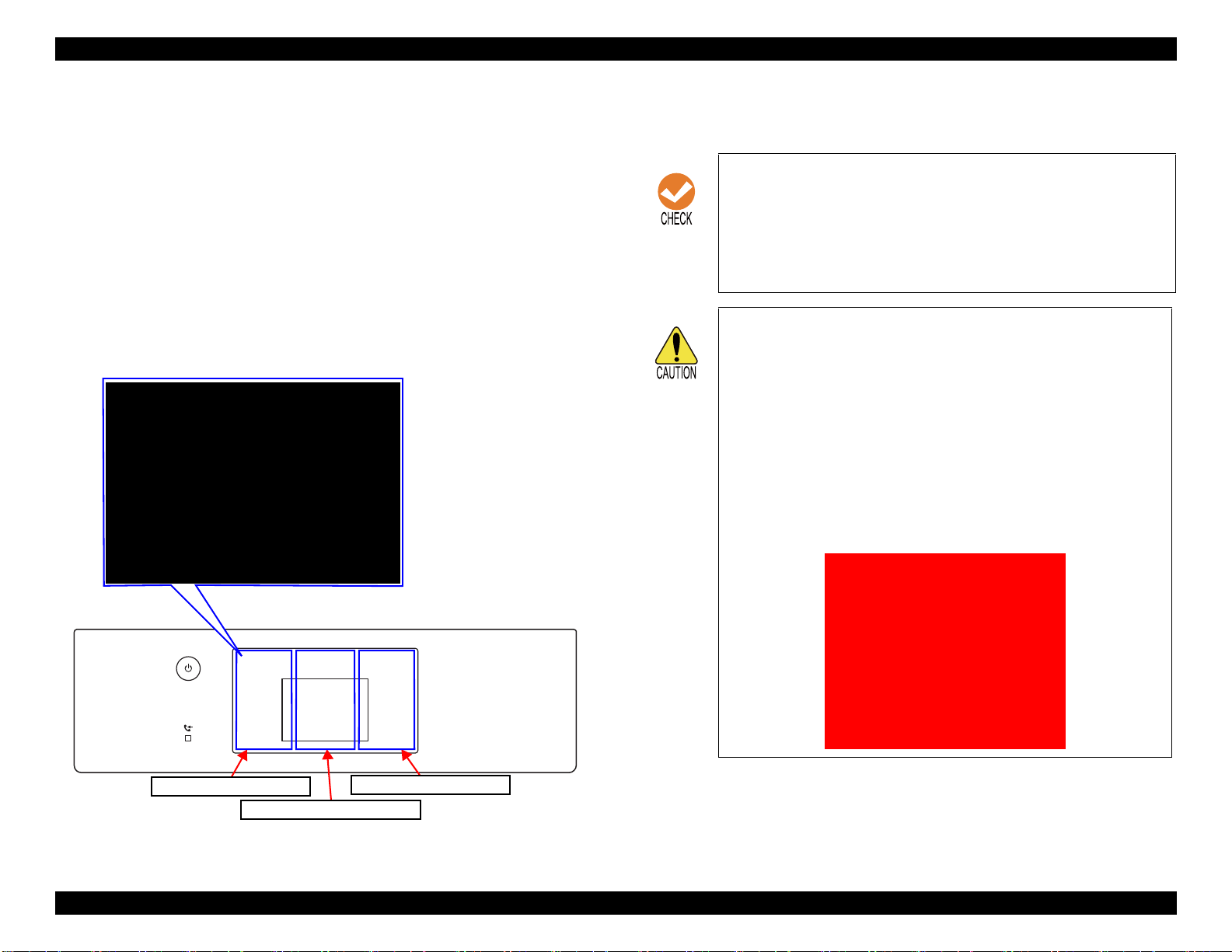
EPSON WF-7820 Series, WF-7830 Series, WF-7840 Series/EC-C7000 Revision A
UP:[Right]
SHIFT:[Left]/FIN:[Center]
*****_
Touch Panel Right [RIGHT]
Touch Panel Left [LEFT]
Touch Panel Center [CENTER]
Input ID is not found!!
Please wait Poweroff...
2. Operate the Touch Panel, and enter the ID.
ID to enter: 98308
Operating procedure
1. Tap the Touch Panel Right [RIGHT] until the value you wish to
input is displayed.
2. Tap the Touch Panel Left [LEFT] to check the value. The value
will change to “*”, and await entry of the next digit.
3. Repeat steps 1 and 2 to enter the 5 digit ID.
4. When entry is completed, tap the Touch Panel Center [CENTER]
to confirm.
3. Hereafter, use the Touch Panel Right [RIGHT] to select the menu, and
execute with the Touch Panel Center [CENTER].
It is not possible to return to the previous digit after
shifting digits. If you wish to correct the number of the
previous digit, proceed with the steps until after the last
step and then perform input again.
Please note that the execute button is not enabled until at
least two digits have been entered.
Solution if enter and execute the wrong ID
When a different mode starts:
If you enter the wrong ID and a different mode starts,
there is the possibility of changing important settings of
the unit, so press the power button to turn off the power
immediately and then perform the process again to enter
the correct ID number.
When non-existent ID number:
The following panel LCD display appears and the power
is turned off automatically.
Figure 2-6. Service support mode operation method
Troubleshooting Service Support Mode 81
Confidential
Page 82

EPSON WF-7820 Series, WF-7830 Series, WF-7840 Series/EC-C7000 Revision A
2.4.4 Status Sheet Information
This section explains about each item printed on the status sheets.
The following status sheets can be printed from the printer.
Overview of Status Sheets
Configuration Status Sheet: printer settings information
Supply Status Sheet: supported model numbers of consumables or periodic replacement
parts, and the total number of sheets fed into the printer.
Usage History Sheet: usage history such as the total number of printed pages per function.
Service Status Sheet: in addition to the information included in the above three sheets, information required for servicing is also provided.
However, the status sheet can be printed only in service support mode. (p 79)
Status Sheet Items
Configuration Status Sheet (total pages: 1 sheet)
Item Explanation
Device ID Device ID (product name) is displayed.
Serial Number The serial number of the product is displayed.
MAC Address MAC address of the product is displayed.
Hardware Configuration
<Hardware> Memory Capacity Capacity of the memory inside the product is displayed.
Firmware Version of the firmware is displayed.
<Version>
Main Firmware Version of the main firmware is displayed.
Network Firmware Version of the NW firmware is displayed.
QPIT Version of the QPIT is displayed.
Troubleshooting Service Support Mode 82
Confidential
Page 83

EPSON WF-7820 Series, WF-7830 Series, WF-7840 Series/EC-C7000 Revision A
Item Explanation
The current language setting is displayed.
Sound level setting (0 to 10) is displayed.
Whether the sleep timer is enabled or not is displayed. When enabled, the time
period before the product enters sleep mode is also displayed.
Whether the auto power off setting is enabled or not is displayed. When enabled, the
time period before the printer automatically turns off is also displayed.
The Ink Drying Time when duplex printing is displayed.
Whether the setting is enabled or not is displayed.
Whether the setting is enabled or not is displayed.
Whether the setting is enabled or not is displayed.
Basic settings
Printer settings
Language
Mute The setting of mute (on/off) is displayed.
Button Press
ADF set sound
Receive Completion Notice
Error Notice
<Sound settings>
Sleep timer
Power Off Timer
Auto Error Solver Whether the auto error resolver options are enabled or not is displayed.
Memory Device Interface
Ink Drying Time
PC connection via USB
Thick Paper Whether the setting is enabled or not is displayed.
Quiet Mode
Paper Ejection Tray Auto Extension
Normal
Memory Device Whether the setting is enabled or not is displayed.
File Sharing Whether to prefer USB connection or to prefer network connection is displayed.
Receive Completion Notice
Send Completion Notice
Print Completion Notice
Ring Tone
Receiver
Sound Type Setting state (pattern 1/pattern 2) is displayed
Troubleshooting Service Support Mode 83
Confidential
Page 84

EPSON WF-7820 Series, WF-7830 Series, WF-7840 Series/EC-C7000 Revision A
Item Explanation
Paper Size Paper size settings for each of the paper sources.
Paper Type Paper type settings for each of the paper sources.
Paper Size Paper size settings for each of the paper sources.
Paper Type Paper type settings for each of the paper sources.
Paper Size Paper size settings of the rear tray is displayed.
Paper Type Paper type settings of the rear tray is displayed.
Cassette 1 Whether the setting is enabled or not is displayed.
Cassette 2 Whether the setting is enabled or not is displayed.
MP tray Whether the setting is enabled or not is displayed.
Cassette 1 Whether the setting is enabled or not is displayed.
Cassette 2 Whether the setting is enabled or not is displayed.
MP tray Whether the setting is enabled or not is displayed.
Cassette 1 Whether the setting is enabled or not is displayed.
Cassette 2 Whether the setting is enabled or not is displayed.
MP tray Whether the setting is enabled or not is displayed.
The offset setting (-30 to 30) is displayed.
Paper source settings
Universal Print Settings
Cassette 1
Paper cassette
Auto Selection
A4/Letter Auto Switching Whether the auto switching function is enabled or not is displayed.
Rear Paper Feed Priority Whether the setting is enabled or not is displayed.
Paper Size Notice Whether the setting is enabled or not is displayed.
Paper Type Notice Whether the setting is enabled or not is displayed.
Top Offset
Left Offset
Top Offset in Back
Left Offset in Back
Check Paper Width Whether the setting is enabled or not is displayed.
Skip Blank Page Whether the setting is enabled or not is displayed.
Cassette 2
MP tray
Copy
Fax
Other
Troubleshooting Service Support Mode 84
Confidential
Page 85

EPSON WF-7820 Series, WF-7830 Series, WF-7840 Series/EC-C7000 Revision A
Item Explanation
Color The color setting (Color or Mono) is displayed.
Document Open Password Whether the password setting is enabled or not is displayed.
Permissions password Whether the password setting is enabled or not is displayed.
Printing Whether printing scanned document is permitted or not is displayed.
Editing Whether editing scanned document is permitted or not is displayed.
Resolution Scan resolution setting (200dpi/300dpi/600dpi) is displayed
2-Sided Printing Scan setting (simplex/duplex) is displayed.
Binding position of documents (left/top/--- (in case of one-side scanning)) is
displayed.
The frame width setting (0 to 40 mm/---(in case of the shadow remove setting is
disabled)) is displayed.
The center width setting (0 to 40 mm/---(in case of the shadow remove setting is
disabled)) is displayed.
The erasing setting (left edge/right edge/top edge/bottom edge/--- (in case of the
remove punch holes setting is disabled)) is displayed.
The erasing amount (0 to 20 mm/--- (in case of the remove punch holes setting is
disabled)) is displayed.
Scan settings
<Common settings>
<Scan to Email>
<Scan to Network
Folder>
Binding Position
Surround
Remove shadow
Center
Erasing Position
Remove Punch Holes
Erase Amount
Orientation (Original) The document orientation setting (portrait or landscape) is displayed.
Document Type The quality setting (Text/Text & Image/Photo) is displayed.
Density The density setting (-4 to 4) is displayed.
Subject The subject of email is displayed.
File Format File format setting is displayed.
Scan area Original document size setting is displayed.
Compression Ratio The Compression Ratio is displayed.
Attached File Max Size The maximum file size that can be attached to an email is displayed.
Filename Prefix File name prefix setting for scanned file is displayed.
Date Whether the setting is enabled or not is displayed.
Time of Day Whether the setting is enabled or not is displayed.
File Format File format setting is displayed.
Scan area Original document size setting is displayed.
Compression Ratio The Compression Ratio is displayed.
Filename Prefix File name prefix setting for scanned file is displayed.
Date Whether the setting is enabled or not is displayed.
Time of Day Whether the setting is enabled or not is displayed.
Troubleshooting Service Support Mode 85
Confidential
Page 86

EPSON WF-7820 Series, WF-7830 Series, WF-7840 Series/EC-C7000 Revision A
Item Explanation
File Format File format setting is displayed.
Scan area Original document size setting is displayed.
Compression Ratio The Compression Ratio is displayed.
Filename Prefix File name prefix setting for scanned file is displayed.
Date Whether the setting is enabled or not is displayed.
Time of Day Whether the setting is enabled or not is displayed.
File Format File format setting is displayed.
Scan area Original document size setting is displayed.
Scan settings
<Scan to Memory
Device>
<Scan to Cloud>
Troubleshooting Service Support Mode 86
Confidential
Page 87

EPSON WF-7820 Series, WF-7830 Series, WF-7840 Series/EC-C7000 Revision A
Supply Status Sheet (total pages: 1 sheet)
Item Explanation
Device ID Device ID (product name) is displayed.
Serial Number The serial number of the product is displayed.
MAC Address MAC address of the product is displayed.
<Hardware> Memory Capacity Capacity of the memory inside the product is displayed.
Firmware Version of the firmware is displayed.
<Version>
Hardware Configuration
Ink Cartridge
Maintenance Box Product number Product number of the Maintenance Box is displayed.
Main Firmware Version of the main firmware is displayed.
Network Firmware Version of the NW firmware is displayed.
QPIT Version of the QPIT is displayed.
Black
Cyan
Magenta
Yellow
Product Number
Serial Number
Product Number
Serial Number
Product Number
Serial Number
Product Number
Serial Number
Product number of the ink cartridge is displayed.
Troubleshooting Service Support Mode 87
Confidential
Page 88

EPSON WF-7820 Series, WF-7830 Series, WF-7840 Series/EC-C7000 Revision A
Usage History Sheet (total pages: 1 sheet)
Item Explanation
Hardware Configuration
Hardware Configuration
Usage History First Time Printing The date and time when the printer printed for the first time is displayed.
Number of Pages
Device ID Device ID (product name) is displayed.
Serial Number The serial number of the product is displayed.
MAC Address MAC address of the product is displayed.
<Hardware> Memory Capacity Capacity of the memory inside the product is displayed.
Firmware Version of the firmware is displayed.
<Version>
<Sorted by Function>
<Sorted by Paper Size>
(1-sided/2- sided, B&W/
Color)
<Sorted by Usage>
<Sorted by Printer
Language>
Main Firmware Version of the main firmware is displayed.
Network Firmware Version of the NW firmware is displayed.
QPIT Version of the QPIT is displayed.
Total Number of Pages The total number of printed pages is displayed.
Total Number of B&W Pages The total number of pages printed in monochrome is displayed.
Total Number of Color Pages The total number of pages printed in color is displayed.
Total Number of 2-Sided Printing Pages The total number of printed 2-sided pages is displayed.
Total Number of 1-Sided Printing Pages The total number of printed one-sided pages is displayed.
A3/Ledger
A4/Letter
A5
A6
B4/Legal
B5
Envelope
Others
B&W Copy
Color Copy
B&W Fax
Color Fax
B&W Print from Computer or Mobile Device
Color Print from Computer or Mobile Device
B&W Print from Memory Device or Other Functions
Color Print from Memory Device or Other Functions
ESC/P-R
Other
The total number of printed pages per paper size is displayed.
Detailed count per function (one-sided/2-sided, monochrome/color) is also
displayed for each paper size.
The total number of printed pages for each of the purposes is displayed.
The version of each of the printer language is displayed.
Troubleshooting Service Support Mode 88
Confidential
Page 89

EPSON WF-7820 Series, WF-7830 Series, WF-7840 Series/EC-C7000 Revision A
Item Explanation
Number of Scan Pages
B&W Scan Number of sheets scanned in monochrome.
Color Scan Number of sheets scanned in color.
Troubleshooting Service Support Mode 89
Confidential
Page 90

EPSON WF-7820 Series, WF-7830 Series, WF-7840 Series/EC-C7000 Revision A
Service Status Sheet (total pages:9 sheets)
Item Explanation
Device ID Device ID (product name) is displayed.
Serial Number The serial number of the product is displayed.
MAC Address MAC address of the product is displayed.
Hardware Configuration
Basic Settings
Printer settings
<Hardware> Memory Capacity Capacity of the memory inside the product is displayed.
Firmware Version of the firmware is displayed.
<Version>
Language The current language setting is displayed.
<Sound settings>
Sleep timer
Power Off Timer
Auto Error Solver
Memory Device Interface
Ink Drying Time
PC connection via USB
Thick Paper Whether the setting is enabled or not is displayed.
Quiet Mode
Main Firmware Version of the main firmware is displayed.
Network Firmware Version of the NW firmware is displayed.
QPIT Version of the QPIT is displayed.
Mute The setting of mute (on/off) is displayed.
Button Press
ADF set sound
Receive Completion Notice
Error Notice
Normal
Memory Device Whether the setting is enabled or not is displayed.
File Sharing Whether to prefer USB connection or to prefer network connection is displayed.
Receive Completion Notice
Send Completion Notice
Print Completion Notice
Ring Tone
Receiver
Sound Type Setting state (pattern 1/pattern 2) is displayed
Sound level setting (0 to 10) is displayed.
Whether the sleep timer is enabled or not is displayed. When enabled, the time
period before the product enters sleep mode is also displayed.
Whether the auto power off setting is enabled or not is displayed. When enabled, the
time period before the printer automatically turns off is also displayed.
Whether the auto error resolver options are enabled or not is displayed.
The Ink Drying Time when duplex printing is displayed.
Whether the setting is enabled or not is displayed.
Whether the setting is enabled or not is displayed.
Troubleshooting Service Support Mode 90
Confidential
Page 91

EPSON WF-7820 Series, WF-7830 Series, WF-7840 Series/EC-C7000 Revision A
Item Explanation
Paper Size Paper size settings for each of the paper sources.
Paper Type Paper type settings for each of the paper sources.
Paper Size Paper size settings for each of the paper sources.
Paper Type Paper type settings for each of the paper sources.
Paper Size Paper size settings of the rear tray is displayed.
Paper Type Paper type settings of the rear tray is displayed.
Cassette 1 Whether the setting is enabled or not is displayed.
Cassette 2 Whether the setting is enabled or not is displayed.
MP tray Whether the setting is enabled or not is displayed.
Cassette 1 Whether the setting is enabled or not is displayed.
Cassette 2 Whether the setting is enabled or not is displayed.
MP tray Whether the setting is enabled or not is displayed.
Cassette 1 Whether the setting is enabled or not is displayed.
Cassette 2 Whether the setting is enabled or not is displayed.
MP tray Whether the setting is enabled or not is displayed.
The offset setting (-30 to 30) is displayed.
Paper source settings
Universal Print Settings
Cassette 1
Paper cassette
Auto Selection
A4/Letter Auto Switching Whether the auto switching function is enabled or not is displayed.
Rear Paper Feed Priority Whether the setting is enabled or not is displayed.
Paper Size Notice Whether the setting is enabled or not is displayed.
Paper Type Notice Whether the setting is enabled or not is displayed.
Top Offset
Left Offset
Top Offset in Back
Left Offset in Back
Check Paper Width Whether the setting is enabled or not is displayed.
Skip Blank Page Whether the setting is enabled or not is displayed.
Cassette 2
MP tray
Copy
Fax
Other
Troubleshooting Service Support Mode 91
Confidential
Page 92

EPSON WF-7820 Series, WF-7830 Series, WF-7840 Series/EC-C7000 Revision A
Item Explanation
IP Address
Subnet Mask
Default Gateway
Primary DNS Server
Network Settings
Scan settings <Common settings>
Secondary DNS Server
Proxy Server Settings
Proxy Server
Proxy Server Port Number
DNS Domain Name
Color The color setting (Color or Mono) is displayed.
Document Open Password Whether the password setting is enabled or not is displayed.
Permissions password
Printing Whether printing scanned document is permitted or not is displayed.
Editing
Resolution Scan resolution setting (200dpi/300dpi/600dpi) is displayed
2-Sided Printing Scan setting (simplex/duplex) is displayed.
Binding Position
Surround
Remove shadow
Center
Erasing Position
Remove Punch Holes
Erase Amount
Orientation (Original)
Document Type
Density The density setting (-4 to 4) is displayed.
The network settings are displayed.
Whether the password setting is enabled or not is displayed.
Whether editing scanned document is permitted or not is displayed.
Binding position of documents (left/top/--- (in case of one-side scanning)) is
displayed.
The frame width setting (0 to 40 mm/---(in case of the shadow remove setting is
disabled)) is displayed.
The center width setting (0 to 40 mm/---(in case of the shadow remove setting is
disabled)) is displayed.
The erasing setting (left edge/right edge/top edge/bottom edge/--- (in case of the
remove punch holes setting is disabled)) is displayed.
The erasing amount (0 to 20 mm/--- (in case of the remove punch holes setting is
disabled)) is displayed.
The document orientation setting (portrait or landscape) is displayed.
The quality setting (Text/Text & Image/Photo) is displayed.
Troubleshooting Service Support Mode 92
Confidential
Page 93

EPSON WF-7820 Series, WF-7830 Series, WF-7840 Series/EC-C7000 Revision A
Item Explanation
Subject The subject of email is displayed.
File Format File format setting is displayed.
Scan area Original document size setting is displayed.
<Scan to Email>
Scan settings
Option Settings Fax Function Whether the fax feature is enabled or not is displayed.
Supply Status
<Scan to Network
Folder>
<Scan to Memory
Device>
<Scan to Cloud>
Ink Cartridge
Maintenance Box
Compression Ratio The Compression Ratio is displayed.
Attached File Max Size The maximum file size that can be attached to an email is displayed.
Filename Prefix File name prefix setting for scanned file is displayed.
Date Whether the setting is enabled or not is displayed.
Time of Day Whether the setting is enabled or not is displayed.
File Format File format setting is displayed.
Scan area Original document size setting is displayed.
Compression Ratio The Compression Ratio is displayed.
Filename Prefix File name prefix setting for scanned file is displayed.
Date Whether the setting is enabled or not is displayed.
Time of Day Whether the setting is enabled or not is displayed.
File Format File format setting is displayed.
Scan area Original document size setting is displayed.
Black
Cyan
Magenta
Yellow
Maintenance Box
Product Number
Serial Number
Product Number
Serial Number
Product Number
Serial Number
Product Number
Serial Number
Product number Product number of the Maintenance Box is displayed.
Product number of the ink cartridge is displayed.
Troubleshooting Service Support Mode 93
Confidential
Page 94

EPSON WF-7820 Series, WF-7830 Series, WF-7840 Series/EC-C7000 Revision A
Item Explanation
First Time Printing The date and time when the printer printed for the first time is displayed.
Total Number of Pages The total number of printed pages is displayed.
Total Number of B&W Pages The total number of pages printed in monochrome is displayed.
<Sorted by Function>
<Sorted by Paper Size>
(1-sided/2- sided, B&W/
Color)
Usage History
<Sorted by Usage>
<Sorted by Printer
Language>
Other The Cumulative number of paper jam The total number of times a paper jam error occurs is displayed.
Number of Sheets
Scanned
Number of Sheets Loaded
Total Number of Color Pages The total number of pages printed in color is displayed.
Total Number of 2-Sided Printing Pages The total number of printed 2-sided pages is displayed.
Total Number of 1-Sided Printing Pages The total number of printed one-sided pages is displayed.
A3/Ledger
A4/Letter
A5
A6
B4/Legal
B5
Envelope
Others
B&W Copy
Color Copy
B&W Fax
Color Fax
B&W Print from Computer or Mobile Device
Color Print from Computer or Mobile Device
B&W Print from Memory Device or Other Functions
Color Print from Memory Device or Other Functions
ESC/P-R
Other
Document Table (Number of pages)
ADF (Number of pages)
ADF (Number of Fed Sheets) The total number of document sheets fed by the ADF is displayed.
B&W Scan
Color Scan
Paper Cassette 1
MP tray
The total number of printed pages per paper size is displayed.
Detailed count per function (one-sided/2-sided, monochrome/color) is also
displayed for each paper size.
The total number of printed pages for each of the purposes is displayed.
The version of each of the printer language is displayed.
The total number of pages scanned on the scanner glass or in the ADF is displayed.
Number of sheets scanned is displayed.
The total number of printed pages per paper source is displayed.Paper Cassette 2
Troubleshooting Service Support Mode 94
Confidential
Page 95

EPSON WF-7820 Series, WF-7830 Series, WF-7840 Series/EC-C7000 Revision A
Item Explanation
Printer Error For each of the errors, the following information is displayed.
• Error code
• Sub code
• Date and time of occurrence
• Number of pages to be printed
• Internal temperature
• Internal humidity
• Paper feed path
For each of the errors, the following information is displayed
• Error code
• Date and time of occurrence
• Number of pages to be scanned
For each of the errors, the following information is displayed
• Error code
• Date and time of occurrence
Status of the product (error occurring state) is displayed.Network Error
Error History
Status
Paper Jam Error
Fatal Error When Printing
Scanner Error
Fatal Error When Scanning
Fax Error
Network Error
System Error
Other Error
Printer Error Status of the product (error occurring state) is displayed.
Scanner Error Always “---” is displayed.
Fax Error
Other Error
Troubleshooting Service Support Mode 95
Confidential
Page 96

DISASSEMBLY/ASSEMBLY
CHAPTER
3
Confidential
Page 97

EPSON WF-7820 Series, WF-7830 Series, WF-7840 Series/EC-C7000 Revision A
3.1 Overview
This chapter describes procedures for disassembling the main parts/units of
WF-7820 Series/WF-7830 Series/WF-7840 Series/EC-C7000. Unless
otherwise specified, disassembled parts/units can be reassembled by reversing
the disassembly procedure. Disassembly/reassembly precautions and tips are
give in 3.3.4 Repairing Major Components Disassembly/Assembly Procedure
(P121) and 3.4 Detailed Disassembly/Reassembly Procedure for each Part/
Unit (P152). See the sections as necessary.
Make sure to read Safety Precautions (P3) before starting work.
When you have to remove units or parts that are not described in this chapter,
see the exploded diagrams of SPI (Service Parts Information).
3.1.1 Tools
Use only specified tools to avoid damaging the printer.
Table 3-1. Tools
Name Availability EPSON Part Code
(+) Phillips screwdriver #1 1080530
(+) Phillips screwdriver #2 ---
Flathead screwdriver ---
Flathead Precision screwdriver #1 ---
3.1.2 Jigs
Name Quantity EPSON Part Code
Thickness gauge (1.18 mm) 1 Commercially available
Thickness gauge (1.66 mm) 1 Commercially available
Teflon tape (t = 0.08 mm) 1 Commercially available
Tweezers ---
Longnose pliers ---
Acetate tape --- 1003963
Note 1: “Availability” means that use of a commercially available one is permitted.
2: EPSON provides the tools listed with EPSON part code.
Disassembly/Assembly Overview 97
Confidential
Page 98

EPSON WF-7820 Series, WF-7830 Series, WF-7840 Series/EC-C7000 Revision A
1
2
5
3
4
Front8Right
11
10
9
Left
6
7
Rear
14
13
11
15
Rear
12
1
2
3
4
6
7
8
9
10
Front
5
3.1.3 Locations of the Parts/Units
This section shows the locations of the main parts/units.
The parts/units which can not be seen in the following
pictures are indicated in dotted lines ( ).
Exterior parts
Printer mechanism
No. Name No. Name
1 Rear ASF Unit (p111)
*1
2 CR Scale (p112/p118) 10 Head FFC (p111/p117)
3 Paper Guide Front (p113/p119) 11 Star Wheel Holder (p112/p118)
Porous Pad A (p113/p119)/
4
Porous Pad B (p113/p119)
5 PF Roller (p113/p119) 13 CR Motor (p111/p117)
Paper Guide Upper Left (p113/p119)/
6
Paper Guide Upper Center (p113/p119)/
Paper Guide Upper Right (p113/p119)
Star Wheel Holder Center (p113/p119)
7
8 Printhead (p109/p115)
9 CR Unit (p111/p117)
EJ Roller Center (p113/p119)
12
PE Sensor (p111/p117)
14
Pickup Roller 1st (p110/p116)/
15
Pickup Roller 2nd (p110/p116)
*2
No. Name No. Name
1 ADF/Scanner Unit (p114/p120) 7 Duplex Unit (p110/p116)
2 Paper Cassette 1st (p109/p115) 8 Housing Right (p109/p115)
3 Paper Cassette 2nd (p109/p115)
*1
9 Housing Left (p109/p115)
Note "*1" : WF-7840 Series/EC-C7000/WF-7820 Series only
"*2": WF-7840 Series/EC-C7000/WF-7830 Series only
Figure 3-2. Printer Mechanism (1)
4 Stacker Assy (p110/p116) 10 Housing Upper (p109/p115)
5 Panel Assy (p112/p118) 11 Maintenance Box (p109/p115)
6 Rear ASF Cover Assy (p110)
Note "*1": WF-7840 Series/EC-C7000/WF-7830 Series only
"*2": WF-7840 Series/EC-C7000/WF-7820 Series only
*2
Figure 3-1. Exterior Parts
Disassembly/Assembly Overview 98
Confidential
Page 99

17
16
18
19
20
Right
21
24
22
23
25 26
Left
EPSON WF-7820 Series, WF-7830 Series, WF-7840 Series/EC-C7000 Revision A
3.1.4 Standard Operation Time for Servicing the Product
The following are the standard operation time for servicing the product. This
standard operation time was determined based on the MTTR result measured using
the prototype of WF-7820 Series/WF-7830 Series/WF-7840 Series/EC-C7000.
The underlined parts/units are supplied as After Service Parts.
WF-7820 SERIES/WF-7840 SERIES/EC-C7000
Table 3-2. Standard Operation Time (WF-7820 Series/WF-7840 Series/EC-C7000)
Time (in units of seconds)
No. Name No. Name
16 Auto Stacker Open Unit (p111/p117) 22 Main Board (p112/p118)
17 Inksystem Unit (p111/p117) 23 PS Unit (p109/p115)
18 ASF Motor (p111/p117) 24 Wi-Fi Board (p112/p118)
19 ASF Encoder (p111/p117) 25 PF Encoder (p109/p115)
20 Relay Board (p109/p115) 26 PF Motor (p113/p119)
21 Fax Board (p112)/p118)
Figure 3-3. Printer Mechanism (2)
Parts/Unit
Housing Left
Housing Right
Relay Board 3:06 --- 3:06
Maintenance Box 0:08 --- 0:08
Rear ASF Cover Assy
Rear ASF Cover Left/Right
Rear ASF Cover
Paper Support w/Spring 4:33 --- 4:33
Paper Cassette 1st
Paper Cassette 2nd* 0:10 2:32 2:42
Maintenance Box Cover 0:08 --- 0:08
ADF Document Support
ADF Pad Assy 0:17 --- 0:17
ADF Pad Spring 0:17 --- 0:17
Document Pad
Holder Board Assy 2:19 --- 2:19
CRCM Assy
CSIC Connector (x4)
CSIC Holder
Cover Cable Head Inner 2:36 --- 2:36
Replacement
1:36 --- 1:36
1:40 --- 1:40
3:13 --- 3:13
3:59 --- 3:59
3:59 --- 3:59
0:10 2:32 2:42
0:15 --- 0:15
0:39 --- 0:39
2:37 --- 2:37
3:48 --- 3:48
3:48 --- 3:48
Adjustment/
inspection
Total
Disassembly/Assembly Overview 99
Confidential
Page 100

EPSON WF-7820 Series, WF-7830 Series, WF-7840 Series/EC-C7000 Revision A
Table 3-2. Standard Operation Time (WF-7820 Series/WF-7840 Series/EC-C7000)
Time (in units of seconds)
Parts/Unit
Printhead 4:19 23:24 27:43
Duplex Unit
Retard Roller Assy 0:25 --- 0:25
Pickup Holder 1st 0:17 --- 0:17
Pickup Roller 1st
Paper Guide Cover Assy
(w/Paper Stopper Assy 1st)
Paper Guide Cover Assy
Paper Stopper Assy 1st
Pickup Holder 2nd* 0:49 --- 0:49
Pickup Roller 2nd
Paper Stopper Assy 2nd* 0:54 --- 0:54
ADF Cover Assy 0:14 --- 0:14
ADF Cover
ADF LD Shaft
ADF LD Assy
LD Sub Cover 0:45 --- 0:45
Stacker Assy
PS Plate 2:40 --- 2:40
PS Unit 4:04 1:58 6:02
PF Scale
Holder Gear w/Spring 3:44 --- 3:44
APG Sensor
Holder Gear Spring
APG Cam Left 3:53 --- 3:53
Shaft Spring Left 4:28 --- 4:28
Shaft Spring Right 4:01 --- 4:01
* 1:01 --- 1:01
Replacement
0:08 3:14 3:22
0:29 --- 0:29
0:40 2:40 3:20
1:22 --- 1:22
2:08 --- 2:08
0:52 --- 0:52
1:08 --- 1:08
1:17 --- 1:17
0:08 --- 0:08
1:48 --- 1:48
4:04 --- 4:04
4:06 --- 4:06
Adjustment/
inspection
Total
Table 3-2. Standard Operation Time (WF-7820 Series/WF-7840 Series/EC-C7000)
Time (in units of seconds)
Parts/Unit
PF Encoder 2:24 --- 2:24
PF Encoder FFC
FFC Rail 4:46 --- 4:46
USB Connector Assy 5:57 --- 5:57
USB Connector Holder 2:03 --- 2:03
2nd Bin Assy
Pickup Roller Assy 2nd* 6:57 --- 6:57
ADF/Scanner Unit 7:38 --- 7:38
Housing Upper 5:50 --- 5:50
CR Cover
CR FFC Cover 7:39 --- 7:39
Relay Board FFC 6:09 --- 6:09
Holder Tilt Left 6:15 --- 6:15
Panel Assy
Speaker Cover 6:18 --- 6:18
Speaker Assy
Scanner Open Sensor 6:04 --- 6:04
IS FFC Rail 6:17 --- 6:17
Inksystem Unit
IS Porous Pad 8:55 --- 8:55
Holder Connector Assy 6:52 --- 6:52
* 6:02 8:02 14:04
SC Cable Holder
Scanner Hinge
SC Cable Cover
ADF Unit
Scanner Unit
Replacement
2:44 --- 2:44
8:18 --- 8:18
9:42 --- 9:42
10:07 --- 10:07
10:54 1:28 12:22
10:54 1:28 12:22
6:37 --- 6:37
7:32 --- 7:32
7:12 --- 7:12
8:51 0:30 9:21
Adjustment/
inspection
Total
Disassembly/Assembly Overview 100
Confidential
 Loading...