

Page 1
SERVICE MANUAL
Color Inkjet Printer
Epson WF-7525 / Epson WF-7521 / Epson WF-7520/
Epson WF-7515 / Epson WF-7511 / Epson WF-7510/
Epson WF-7018 / Epson WF-7015 / Epson WF-7012/
Epson WF-7011 / Epson WF-7010
SEMF10-012
Page 2

Notice:
All rights reserved. No part of this manual may be reproduced, stored in a retrieval system, or transmitted in any form or
by any means, electronic, mechanical, photocopying, recording, or otherwise, without the prior written permission of
SEIKO EPSON CORPORATION.
All effort have been made to ensure the accuracy of the contents of this manual. However, should any errors be
detected, SEIKO EPSON would greatly appreciate being informed of them.
The contents of this manual are subject to change without notice.
The above not withstanding SEIKO EPSON CORPORATION can assume no responsibility for any errors in this
manual or the consequences thereof.
EPSON is a registered trademark of SEIKO EPSON CORPORATION.
Note :Other product names used herein are for identification purpose only and may be trademarks or registered
trademarks of their respective owners. EPSON disclaims any and all rights in those marks.
Copyright 2011 SEIKO EPSON CORPORATION
I&I CS Quality Assurance Department
Page 3

Safety Precautions
All safety procedures described here shall be strictly adhered to by all parties servicing and maintaining this
product.
DANGER
Strictly observe the following cautions. Failure to comply could result in serious bodily injury or loss of life.
1. Always disconnect the product from the power source and peripheral devices when servicing the product or
performing maintenance.
2. When performing works described in this manual, do not connect to a power source until instructed to do so.
Connecting to a power source causes high voltage in the power supply unit and some electronic components
even if the product power switch is off. If you need to perform the work with the power cable connected to a
power source, use extreme caution to avoid electrical shock.
WARNING
Strictly observe the following cautions. Failure to comply may lead to personal injury or loss of life.
1. Always wear protective goggles for disassembly and reassembly to protect your eyes from ink in working. If
any ink gets in your eyes, wash your eyes with clean water and consult a doctor immediately.
2. When using compressed air products; such as air duster, for cleaning during repair and maintenance, the use
of such products containing flammable gas is prohibited.
PRECAUTIONS
Strictly observe the following cautions. Failure to comply may lead to personal injury or damage of the product.
1. Repairs on Epson product should be performed only by an Epson certified repair technician.
2. No work should be performed on this product by persons unfamiliar with basic safety knowledge required for
electrician.
3. The power rating of this product is indicated on the serial number/rating plate. Never connect this product to
the power source whose voltages is different from the rated voltage.
4. Replace malfunctioning components only with those components provided or approved by Epson;
introduction of second-source ICs or other non-approved components may damage the product and void any
applicable Epson warranty.
5. The capacitors on the Main Board may be electrically charged right after the power turns off or after driving
motors which generates counter electromotive force such as when rotating the PF Roller or when moving the
CR Unit. There is a risk to damage the Main Board if the Head FFC is short-circuited with the capacitors on
the Main Board electrically charged, therefore, after the power turns off or after motors are driven, leave the
printer untouched for approximately 30 seconds to discharge the capacitors before starting disassembly/
reassembly.
Page 4

6. To prevent the circuit boards from short-circuiting, be careful about the following when handling FFC or
cables.
When handling FFC, take care not to let the terminal section of FFC touch metal parts.
When connecting cables/FFC to the connectors on circuit boards, connect them straight to the connectors to avoid
slant insertion.
7. In order to protect sensitive microprocessors and circuitry, use static discharge equipment, such as anti-static
wrist straps, when accessing internal components.
8. Do not tilt this product immediately after initial ink charge, especially after performing the ink charge several
times. Doing so may cause ink to leak from the product because it may take some time for the waste ink pads
to completely absorb ink wasted due to the ink charge.
9. Never touch the ink or wasted ink with bare hands. If ink comes into contact with your skin, wash it off with
soap and water immediately. If you have a skin irritation, consult a doctor immediately.
10. When disassembling or assembling this product, make sure to wear gloves to avoid injuries from metal parts
with sharp edges.
11. Use only recommended tools for disassembling, assembling or adjusting the printer.
12. Observe the specified torque when tightening screws.
13. Be extremely careful not to scratch or contaminate the following parts.
Nozzle plate of the printhead
CR Scale
PF Scale
Coated surface of the PF Roller
Gears
Rollers
LCD
Scanner Sensor
Exterior parts
14. Never use oil or grease other than those specified in this manual. Use of different types of oil or grease may
damage the component or give bad influence on the printer function.
15. Apply the specified amount of grease described in this manual.
16. Make the specified adjustments when you disassemble the printer.
17. When cleaning this product, follow the procedure described in this manual.
18. When transporting this product after filling the ink in the printhead, pack the printer without removing the
ink cartridges in order to prevent the printhead from drying out.
19. Make sure to install antivirus software in the computers used for the service support activities.
20. Keep the virus pattern file of antivirus software up-to-date.
21. When disassembling/reassembling this product, if you find adhesive power of the double-sided tape which
secure the parts or FFC is not enough, replace the tape with new one and attach it correctly to the specified
points where the parts or FFC should be secured.
22. Unless otherwise specified in this manual, the labels attached on the returned product should be transferred to
the corresponding attachment positions on the new one referring to the labels on the returned product.
Page 5

About This Manual
This manual, consists of the following chapters, is intended for repair service personnel and includes information
necessary for properly performing maintenance and servicing the product.
CHAPTER 1. PRODUCT DESCRIPTIONS
Provides a general overview and specifications of the product.
CHAPTER 2. OPERATING PRINCIPLES
Describes the theory of mechanical operations of the product.
CHAPTER 3. TROUBLESHOOTING
Describes the step-by-step procedures for the troubleshooting.
CHAPTER 4. DISASSEMBLY / REASSEMBLY
Describes the disassembly/reassembly procedures for main parts/units of the product.
CHAPTER 5. ADJUSTMENT
Describes the required adjustments for servicing the product.
CHAPTER 6. MAINTENANCE
Describes maintenance items and procedures for servicing the product.
Symbols Used in this Manual
Various symbols are used throughout this manual either to provide additional information on a specific topic or
to warn of possible danger present during a procedure or an action. Pay attention to all symbols when they are
used, and always read explanation thoroughly and follow the instructions.
Indicates an operating or maintenance procedure, practice or condition that, if not strictly observed,
could result in serious injury or loss of life.
Indicates an operating or maintenance procedure, practice, or condition that, if not strictly observed,
could result in bodily injury, damage or malfunction of equipment.
May indicate an operating or maintenance procedure, practice or condition that is necessary to
accomplish a task efficiently. It may also provide additional information that is related to a specific
subject, or comment on the results achieved through a previous action.
For Chapter 4 “Disassembly/Reassembly”, symbols other than indicated above are used to show additional
information for disassembly/reassembly. For the details on those symbols, see "4.2 Disassembly/Reassembly
Procedures (p46)".
Page 6

Revision Status
Revision Date of Issue Description
A Aug. 24, 2011 First Release
Page 7

Epson WF-7520/7510/7010 series Revision A
Contents
Chapter 1 Product description
1.1 Features . ................................................................................................................................................................... 10
1.2 Printing Specifications . ............................................................................................................................................ 12
1.2.1 Basic Specifications. ........................................................................................................................................ 12
1.3 Scanner Specifications (WF-7520/7510 series only) ............................................................................................... 13
1.3.1 Basic Specifications. ........................................................................................................................................ 13
1.4 Control Panel . ........................................................................................................................................................... 14
1.4.1 Operation Buttons. ........................................................................................................................................... 14
1.4.2 LEDs and LCD Indications ............................................................................................................................. 16
1.5 Various Settings . ...................................................................................................................................................... 19
1.5.1 Panel Operation . .............................................................................................................................................. 19
1.5.1.1 Setup Menu Configuration (WF-7520/7510 series only) ....................................................................... 19
1.5.1.2 Forced Power OFF (WF-7010 series only)............................................................................................. 20
1.5.1.3 Printer Status Sheet ................................................................................................................................. 20
Chapter 2 Operating Principles
2.1 Overview . ................................................................................................................................................................. 22
2.2 Motors and Sensors . ................................................................................................................................................ 22
2.3 Optical Sensor Control . ............................................................................................................................................ 25
2.4 Power-On Sequence . ................................................................................................................................................ 26
Chapter 3 Troubleshooting
3.1 Troubleshooting. ....................................................................................................................................................... 30
3.1.1 Error Message List. .......................................................................................................................................... 30
3.1.2 Troubleshooting Workflow ............................................................................................................................. 31
3.1.3 Fatal Error Code . ............................................................................................................................................. 33
3.1.4 FAX Troubleshooting (WF-7520/7510 series only) ....................................................................................... 37
3.1.4.1 FAX Log ................................................................................................................................................. 37
3.1.4.2 Error Code/Superficial Phenomenon-Based Troubleshooting ............................................................... 42
Chapter 4 Disassembly/Reassembly
4.1 Overview . ................................................................................................................................................................. 45
4.1.1 Tools . ............................................................................................................................................................... 45
4.1.2 Jigs . .................................................................................................................................................................. 45
4.2 Disassembly/Reassembly Procedures . ..................................................................................................................... 46
4.2.1 Parts/Units Need to be Removed in Advance ................................................................................................. 46
4.2.2 Disassembling Flowchart ................................................................................................................................ 48
4.2.2.1 Exterior Parts . ......................................................................................................................................... 48
4.2.2.2 Printer Mechanism .................................................................................................................................. 52
4.3 Detailed Disassembly/Reassembly Procedure for each Part/Unit............................................................................ 55
4.4 Routing FFCs/cables . ............................................................................................................................................... 63
4.5 Connector Summary . ................................................................................................................................................ 67
7
Page 8

Epson WF-7520/7510/7010 series Revision A
Chapter 5 Adjustment
5.1 Required Adjustments .............................................................................................................................................. 69
5.2 Details of Adjustments . ............................................................................................................................................ 75
5.2.1 PF Timing Belt Tension Check ....................................................................................................................... 75
5.2.2 Checking the Platen Gap . ................................................................................................................................ 76
5.2.3 Scanner Timing Belt Tension Check . .............................................................................................................. 77
5.2.4 MAC Address Setting. ..................................................................................................................................... 78
Chapter 6 Maintenance
6.1 Overview . ................................................................................................................................................................. 80
6.1.1 Cleaning . .......................................................................................................................................................... 80
6.1.2 Lubrication. ...................................................................................................................................................... 80
6.2 Lubrication Points and Instructions.......................................................................................................................... 81
8
Page 9

CHAPTER 1
PRODUCT DESCRIPTION
Page 10

Epson WF-7520/7510/7010 series Revision A
1.1 Features
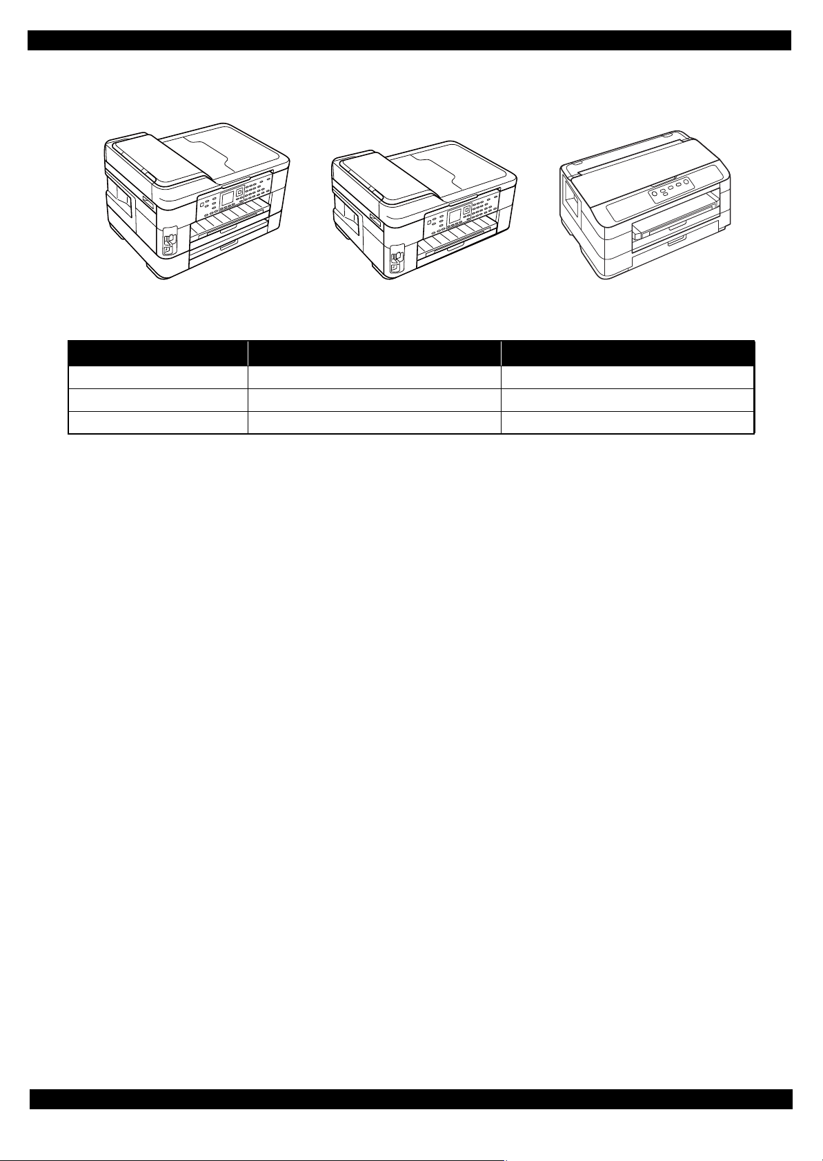
In this chapter, the product names are called as follows:
WF-7520 series: Epson WF-7525/Epson WF-7521/Epson WF-7520
WF-7510 series: Epson WF-7515/Epson WF-7511/Epson WF-7510
WF-7010 series: Epson WF-7018/Epson WF-7015/Epson WF-7012/Epson WF-7011/
Epson WF-7010
WF-7520/7510/7010 series are an A3 color inkjet printer based on Epson WorkForce 840/Epson Stylus Office
BX925FWD. Major features are as follows.
Common futures
Printer
Maximum print speed: 15 ppm (A4, monochrome, draft printing mode)
O6-Chip Turbo 2 Printhead (Black: 128 nozzles x 3, Color: 128 nozzles x 1 per color)
Maximum print resolution: 5760 x 1440 dpi
Auto duplex printing up to A3 paper with the Duplex Unit (WF-7520/7010 series only)
Four independent ink cartridges are installed (pigment inks)
Interface
In addition to USB connection, wired/wireless LAN connection are available
Scanner (WF-7520/7510 series only)
CIS type sensor (scanning resolution: 1200 x 2400 dpi)
ADF up to A3 paper scanning
Note"*": Auto duplex scanning is available only for WF-7520 series. (A4 or letter sized paper only)
*
Differences between the models
WF-7520/7510/7010 series are different as shown below.
Table 1-1. Differences between the Models
Item WF-7520 series WF-7510 series WF-7010 series
LCD display size 2.5 inch 2.5 inch No
Auto duplex printing Yes No Yes
Scanner / ADF Yes Yes No
USB host
(for PictBridge / Backup of an external storage device)
FAX Yes Yes No
Wi-Fi Yes Yes Yes
2nd cassette Yes No Yes
Note *: The availability of the WiFi varies depending on the destinations.
Available: EHC/Euro/CISMEA/ESP/ETT/EKL
Not available: EAL/Latin/EAL/ECC/EHK
Yes Yes No
*
Product description Features 10
Page 11
Epson WF-7520/7510/7010 series Revision A
WF-7520 series WF-7510 series WF-7010 series
External view
Figure 1-1. External View
Table 1-2. Dimensions
Model Dimensions (W x D x H)
WF-7520 series 559 mm x 418 mm x 365 mm 18.9 kg
WF-7510 series 559 mm x 418 mm x 287 mm 15.6 kg
WF-7010 series 558 mm x 414 mm x 264 mm 12.3 kg
*1
Weight
*2
Note *1: Paper support for rear ASF and stacker are closed. Rubber feet are included.
*2: Excluding the weight of ink cartridges and power cable.
Product description Features 11
Page 12

Epson WF-7520/7510/7010 series Revision A
1.2 Printing Specifications
1.2.1 Basic Specifications
Table 1-3. Printer Specifications
Item Specification
Print method On-demand ink jet
Nozzle configuration Black: 384 nozzles (128 nozzles x 3)
Color: 384 nozzles (128 nozzles x 1 per color)
Color Black, Cyan, Magenta, Yellow
Print direction Bi-directional minimum distance printing, Unidirectional printing
Print resolution Horizontal x Vertical (dpi)
• 360 x 120
• 360 x 360
• 360 x 720
Control code • ESC/P Raster command
• ESC/P-R (RGB) command
Input buffer size Printing from PC: 64 KBytes
Stand-alone printing: 132 KBytes
Paper feed method Friction feed
Paper feed amount 250 pages (plain paper*), 20 pages (photo paper), 50 pages (postcard)
Paper path Front feed, front out
PF interval 0.01764 mm (1/1440 inch)
• 720 x 720
• 1440 x 720
• 5760 x 1440
Note *: For paper thickness: 0.11 mm, 80 g/m2.
Product description Printing Specifications 12
Page 13

Epson WF-7520/7510/7010 series Revision A
1.3 Scanner Specifications (WF-7520/7510 series only)
1.3.1 Basic Specifications
Table 1-4. Basic Specifications
Item Specification
Scanner type Flatbed, color
Scanning method Moving carriage, stationary document
Home position The rear left corner
Photoelectric device CIS
Light source LED
Maximum document sizes A3 or US B (tabloid)
Scanning range 11.7” x 17” (297 mm x 431.8 mm)
Maximum resolution Main scan: 1,200 dpi
Sub scan: 2,400 dpi
Maximum effective pixels 14,040 x 20,400 pixels
Pixel depth 16 bit per pixel (input) and 1 bit or 8 bit per pixel (output)
Table 1-5. ADF Specifications
Item Specification
Document loading Face-up
Maximum document sizes A4 to A3/tabloid
Supported paper type Plain paper only
Paper thickness 64 to 95 g/m
Maximum number of documents which can be set 30 sheets or 3 mm at maximum
Document path Feeds from upper tray and ejects to lower tray
Document set position Center
Auto duplex scanning
Note *: WF-7520 series only
*
A4 or US Letter only
2
Product description Scanner Specifications (WF-7520/7510 series only) 13
Page 14
Epson WF-7520/7510/7010 series Revision A
WF-7520 series only
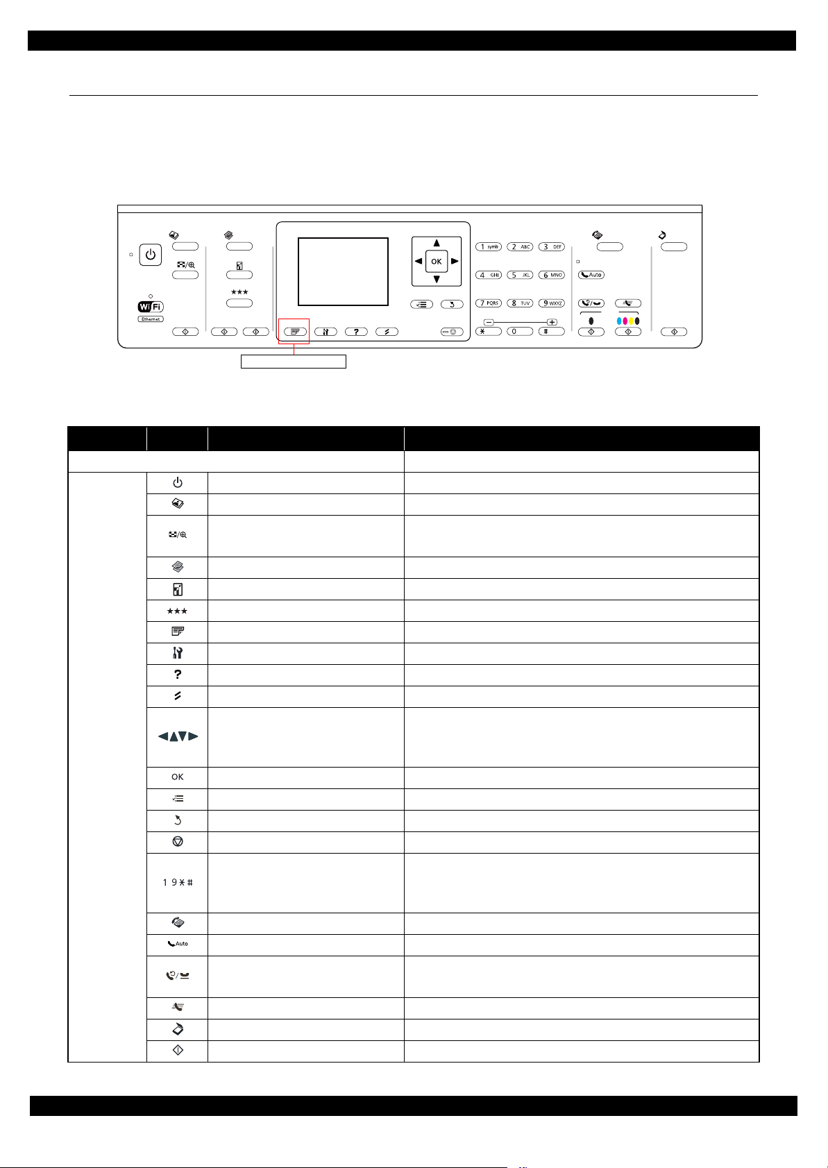
1.4 Control Panel
1.4.1 Operation Buttons
The operation buttons, LEDs, and LCD are shown below. See Table 1-6 and Table 1-7 for the functions.
WF-7520/7510 series
Photo Fax
Print
Copy
Menu
Back
Stop
Start
Figure 1-2. Control Panel (WF-7520/7510 series)
Table 1-6. Operation Buttons, LEDs and LCD (WF-7520/7510 series)
Item Icon Name Function
LCD Indicates the printer status, error, and menu screen.
Power Turns the power on/off.
Photo Enters photo mode.
• Enters zoom setting screen for selected image.
• Switches preview screens on LCD.
• Selects menus.
• Specifies the number of copies.
• Moves the cursor in fax mode.
• Specifies the date/time
• Specifies the number of copies
• Specifies fax numbers
Button/
touch panel
Display/Crop
Copy Enters copy mode.
Reduce/Enlarge Specifies copy magnification.
Quality Specifies print quality.
2-Sided Specifies auto duplex print setting. (WF-7520 series only)
Setup Enters setup mode.
Help Displays help for solutions to problems.
Reset Resets the current setting and displays the home screen.
Arrows
OK Activates the setting you have selected.
Menu Displays detailed settings for each mode.
Back Cancels/returns to the previous menu.
Stop Stops printing.
-
,
,
Ten key
Scan
Start
Fax Enters fax mode.
Auto Answer Turns on/off auto answer mode.
Redial/Pause
• Displays the last number dialed.
• Inserts a pause symbol (-) when entering numbers in fax mode.
Speed Dial Displays speed dial list in fax mode.
Scan Enters scan mode.
Start Starts copying in each mode.
Product description Control Panel 14
Page 15
Epson WF-7520/7510/7010 series Revision A
Note : The WiFi logo and button on the control panel vary
depending on the destinations. (See Table 1-1.)
Table 1-6. Operation Buttons, LEDs and LCD (WF-7520/7510 series)
Item Icon Name Function
Power
LED
Note : See "1.4.2 LEDs and LCD Indications (p16)" for more details about the LCD.
Network Indicates the network connection status.
Auto Answer On when the fax is in auto answer mode.
• Lights when the printer is on.
• Flashes when the printer is in process.
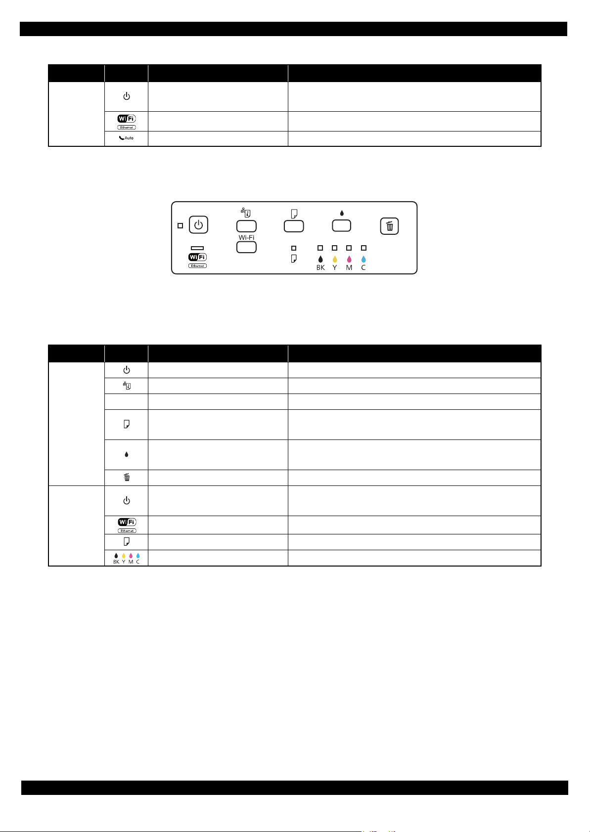
WF-7010 series
Figure 1-3. Control Panel (WF-7010 series)
Table 1-7. Operation Buttons and LEDs (WF-7010 series)
Item Icon Name Function
Power Turns the power on/off.
Network status sheet Prints a network status sheet.
---
Button
LED
Note : See "1.4.2 LEDs and LCD Indications (p16)" for more details about the LEDs.
Note *: The corresponding color LED is indicated.
Wi-Fi Configures the wireless network.
Paper feed/eject
Ink
Cancel Cancels printing during a print job.
Power
Network Indicates the network connection status.
Paper Indicates error status for paper.
*
Ink
• Loads or ejects paper.
• Resumes printing after a paper out error, multiple page feed error.
• Starts ink replacement.
• Starts head cleaning.
• Lights when the printer is on.
• Flashes when the printer is in process.
Indicates error status for ink.
Product description Control Panel 15
Page 16
Epson WF-7520/7510/7010 series Revision A
1.4.2 LEDs and LCD Indications
Table 1-8. LEDs and LCD Indications
WF-7010 series WF-7520/7510 series
Operating
Status
LED
LCD Message
Power Network Paper Ink
Printer error. Turn power off and then on
again. For details, see your documentation or
visit Epson.com.
Paper jam inside, in back, or in ADF. Press
OK to see how to remove jammed paper.
Scanner error. Turn power off and then on
again. In the error is not fixed, visit
Printer fatal error
Printer fatal error
(paper jam)
Scanner fatal error
*1
Flash at
high speed
Flash at
high speed
Flash at
high speed
Flash at
high speed
Flash at
high speed
Flash at
high speed
--- --- --- ---
Flash at
high speed
Flash at
high speed
Epson.com for technical support.
ADF fatal error
ADF paper jam error
Waste ink pad end error Flash
Waste ink pad near end
error
Paper jam error Flash
No paper cassette error Flash
Paper out error Flash
Multi-feed error Flash
Paper length mismatch
error for duplex
printing
Paper size mismatch
error
Incorrect paper size
*1
error
Printer/printer driver
mismatch error
*1
*1
*3
--- --- --- --- Automatic Document Feeder (ADF) error.
--- --- --- ---
Alternate
flash 1
Alternate
flash 1
Flash
Flash
Flash
*2
*2
*2
*2
*2
*2
*2
*2
---
---
--- Flash ---
--- ON ---
--- ON ---
--- ON ---
--- ON ---
--- ON ---
Alternate
flash 2
Alternate
flash 2
Paper jam in the Automatic Document
Feeder (ADF).
A printer's ink pad is at the end of its service
life. Please contact Epson Support.
A printer's ink pad is nearing the end of its
service life. Please contact Epson Support.
Paper jam. Press OK to see how to remove
jammed paper.
Load Cassette correctly and press or
.
Paper out or paper jam. Check paper size and
load paper in paper cassette.
Multi-page feed error. Remove and reload
the paper, then press or .
Incorrect paper size detected. Load correct
paper size and press or .
No paper source matches paper size setting.
Load appropriate paper in Cassette 1. Press
or .
--- --- --- ---
Flash
*2
---
Flash at
high speed
Flash at
high speed
Paper size is incorrect. Load US B 11x17in
size plain paper in Cassette.
Error Press .
Cover open error Flash --- Flash 2 Flash 2 Close the scanner unit.
You need to replace the following ink
*4
cartridge(s).
Ink end error Flash
*2
--- --- ON
<Ink Cartridges>XXXXXXX
Ink cartridge detection
error
Flash
Ink cartridge detection
error (non-Epson
Flash
cartridge)
No ink cartridge error Flash
*2
*2
*2
--- --- ON
--- --- ON
--- --- ON
Cannot recognize the following cartridge(s).
*4
Try installing them again.
<Ink Cartridges>XXXXXXX
Ink cartridge is not recognized. Please
*4
replace the cartridge.
<Ink Cartridges>XXXXXXX
The cartridge is installed incorrectly. Press it
*4
down until it clicks.
<Ink Cartridges>XXXXXXX
*5
*5
*5
*5
Product description Control Panel 16
Page 17

Epson WF-7520/7510/7010 series Revision A
Table 1-8. LEDs and LCD Indications
WF-7010 series WF-7520/7510 series
Operating
Status
LED
LCD Message
Power Network Paper Ink
Starting filling of ink
(after carriage moves)
Ink cartridge cover open
error
Flash --- --- ---
*2
Flash
--- --- ---
Starting initialization Flash --- --- ---
Replace the cartridge(s) and close the
scanner unit.
<Ink Cartridges>XXXXXXX
*5
The ink cartridge cover is open. Close the ink
cartridge cover.
Install the ink cartridges. See the setup sheet
for details.
Initializing...Please wait.
Initializing Flash --- --- ---
Do not turn off until initialization is
complete. This takes about 7 minutes.
Filling of ink Flash --- --- --- Charging ink...Please wait.
Checking ink cartridges Flash --- --- --- Checking the ink cartridges...
Drying 1st side
(printing from PC)
Flash --- --- ---
Printing 2-sided document. Do not touch the
paper in the output tray until printing is
complete.
Printing (PC) Flash --- --- --- Printing...
Printing nozzle check
pattern
Printing printer status
sheet
Flash --- --- --- Printing...
Flash --- --- --- Printing...
Printing (UPNP) Flash Flash --- --- Printing...
Receiving data Flash Flash --- --- Receiving data...
Canceling (PC)
*6
Flash --- --- --- Canceling...
Cleaning (PC) Flash --- --- --- Cleaning print head...Please wait.
Print head cleaning Flash --- --- --- Cleaning print head...Please wait.
Canceling nozzle check
pattern print
Canceling printer status
sheet print
Initializing network Flash
Waiting for network
initialization
Network initialization
(LED ON)
Network initialization
(LED OFF)
Preparing to update
firmware (cancel OK)
Updating firmware Flash
Flash --- --- --- Canceling...
Flash --- --- --- Canceling...
Flash
OFF
OFF
ON
*2
*2
*2
*2
*2
*7
Flash --- --- ---
--- --- --- ---
ON --- --- ---
OFF --- --- ---
Flash at
high speed
--- --- Preparing to update...
Updating firmware...Do not turn power off.
OFF OFF OFF
It turns off and on automatically when
complete.
Preparing to update
firmware
Canceling firmware
update
ON
ON
*2
*2
Flash at
high speed
Flash at
high speed
--- --- Preparing to update...
--- --- Canceling...
Product description Control Panel 17
Page 18

Epson WF-7520/7510/7010 series Revision A
Table 1-8. LEDs and LCD Indications
WF-7010 series WF-7520/7510 series
Operating
Standby
Operating/
*8
Standby
Status
LED
LCD Message
Power Network Paper Ink
Powering OFF
Flash at
high speed
--- --- --- Turning off...
Powering ON Flash Flash --- --- Starting up...Please wait.
Feeding a paper
(load/eject)
Flash --- --- --- Printing...
No error ON --- --- --- ---
Ink level low ON
Waste ink pad near end
error
ON
Requiring ink cartridges
(carriage is at the
Flash --- --- ---
replacement position)
Ink end error
(during Bk mode)
Ink end error
(out of Bk mode)
ON
ON
No ink cartridge error ON
*2
*2
*2
*2
*2
--- --- Flash
---
Alternate
flash 1
--- --- ON
--- --- ON
--- --- ON
*4
Alternate
flash 2
*4
*4
*4
Ink low.
A printer's ink pad is nearing the end of its
service life. Please contact Epson Support.
Replace the cartridge(s) and close the
scanner unit.
<Ink Cartridges>XXXXXXX
You can temporarily copy, print and fax in
B&W on plain paper on the next job.
You need to replace the following ink
cartridge(s).
<Ink Cartridges>XXXXXXX
The cartridge is installed incorrectly. Press it
down until it clicks.
<Ink Cartridges>XXXXXXX
Ink cartridge detection
error
Ink cartridge detection
error (non-Epson
cartridge)
ON
ON
*2
*2
--- --- ON
--- --- ON
Cannot recognize the following cartridge(s).
*4
Try installing them again.
<Ink Cartridges>XXXXXXX
Ink cartridge is not recognized. Please
*4
replace the cartridge.
<Ink Cartridges>XXXXXXX
When starting up --- Flash --- --- ---
Not connected --- --- --- --- ---
Connected via wired
LAN (with IP)
--- ON --- --- ---
*5
*5
*5
*5
*5
Note : Flash Turns on and off at intervals of 1.25 seconds.
Flash 2 On for 0.5 sec., Off for 0.5 sec., On for 0.5 sec. and Off for 1.0 sec.
Flash at high speed Turns on and off at intervals of 0.5 seconds.
Alternate flash 1 Same as “Flash”
Alternate flash 2 Turns on and off at intervals of 1.25 seconds.
Note *1: WF-7520/7510 series only
*2: Flashes if the status arises when printing starts or when the printer starts up, but lights if the status arises when printing is
complete.
*3: WF-7520/7010 series only
*4: The corresponding ink LED flashes/lights.
*5: The corresponding ink cartridge product number is indicated.
*6: Occurs when cancelling printing from PC, UPNP printing.
*7: Lights and then flashes.
*8: This does not occur independently. Occurs together with operating or standby state.
Product description Control Panel 18
Page 19
Epson WF-7520/7510/7010 series Revision A
1.5 Various Settings
1.5.1 Panel Operation
1.5.1.1 Setup Menu Configuration (WF-7520/7510 series only)
The following explains the setup menu structure and the outline of the menu functions.
Table 1-9. Setup Menu Configuration (WF-7520/7510 series only)
Menu Description
Setup Ink Levels --- Displays the status of ink cartridges.
Maintenance Print Head Nozzle Check Prints a nozzle check pattern.
Print Head Cleaning Runs a print head cleaning.
Print Head Alignment Prints a gap adjustment pattern.
Ink Cartridge Replacement Starts ink cartridge replacement.
Printer Setup Paper Size Loaded
Sound Turns the sound on/off.
Screen Saver
Display Format Specifies display format for the images in the memory card.
Date/Time Selects display format for data/time.
Daylight Saving Time Selects daylight saving time.
Country/Region Selects country/region.
Language Selects the language displayed on the LCD.
Paper Size Notice
Wi-Fi/Network
Settings
File Sharing Setup USB
External Device
Setup
Print Status Sheet --- Prints a printer status sheet.
Restore Default
Settings
Wi-Fi Setup Selects a connection method for wireless LAN.
General Network Setup
Wi-Fi/Network Connection
Check
Confirm Network Settings • Displays the network information.
Wi-Fi/Network
Print Settings Configures the print and paper settings when printing an image in
Photo Adjustments Configures the color correction for photo.
Reset Fax Send/Receive
Settings
Reset Fax Data Settings Deletes the fax data settings.
Reset Wi-Fi/Network
Settings
Reset All except Wi-Fi/
Network & Fax Settings
Reset All Settings Initializes the all settings.
*1
*2
*1
Selects the paper size.
Configures the screen saver setting.
Checks the paper size and selects whether to alert users when an
error occurs (Off/On).
Configures the general setting for network.
• Checks the network connection status.
• Prints the connection check result.
• Prints a network status sheet.
Sets the access priority when accessing the storage device
connected to the USB host port to USB or Wi-Fi/Network.
external device.
Initializes the fax send/receive settings.
Initializes the Wi-Fi/network settings.
Initializes the settings except Wi-Fi/network/fax settings.
Note *1: WF-7520 series only
*2: Not available for some destinations.
Product description Various Settings 19
Page 20

Epson WF-7520/7510/7010 series Revision A
1.5.1.2 Forced Power OFF (WF-7010 series only)
For WF-7010 series, the power can be turned off forcibly by the following panel operation. If the power is turned
off forcibly, the same process of the normal power-off is executed.
Operation method
1. Press the power button and then stop button, and hold down the buttons for seven seconds or more.
2. When the Power LED starts flashing, release the buttons.
1.5.1.3 Printer Status Sheet
WF-7520/7510/7010 series print the printer status sheet by the following operation.
Table 1-10. Status Sheet
Model Procedure
WF-7520/7510 series 1. Press the setup button.
2. Select “Print Status Sheet” from the setup menu.
3. Press the OK button.
WF-7010 series Turn the power on while pressing the paper feed/eject button.
Note : When printing the network status sheet to check the network information, follow the procedure below.
WF-7520/7510 series: Select “Wi-Fi/Network Settings” - “Confirm Wi-Fi/Network Settings”, and press th
(See "1.5.1.1 Setup Menu Configuration (WF-7520/7510 series only) (p19) ".)
WF-7010 series: Press the “network status sheet” button. (See
"1.4.1 Operation Buttons (p14)"
.)
e OK butt
on.
Product description Various Settings 20
Page 21

CHAPTER 2
OPERATING PRINCIPLES
Page 22
Epson WF-7520/7510/7010 series Revision A
A
Printhead
1
2
5
3
4
B
7
6
2.1 Overview
In this chapter, the product names are called as follows:
WF-7520 series: Epson WF-7525/Epson WF-7521/Epson WF-7520
WF-7510 series: Epson WF-7515/Epson WF-7511/Epson WF-7510
WF-7010 series: Epson WF-7018/Epson WF-7015/Epson WF-7012/Epson WF-7011/
Epson WF-7010
This chapter describes the operating principles of WF-7520/7510/7010 series printer mechanism.
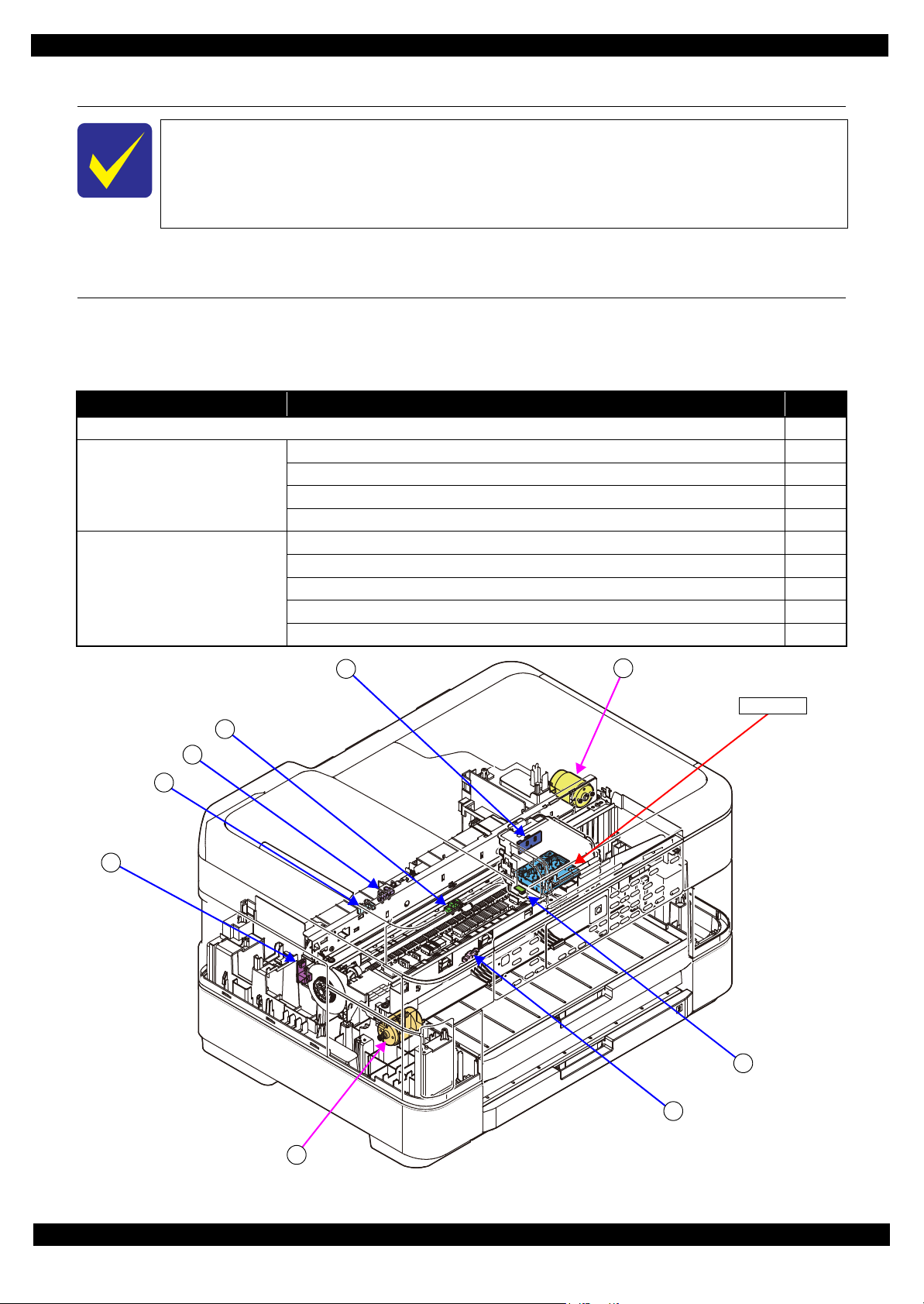
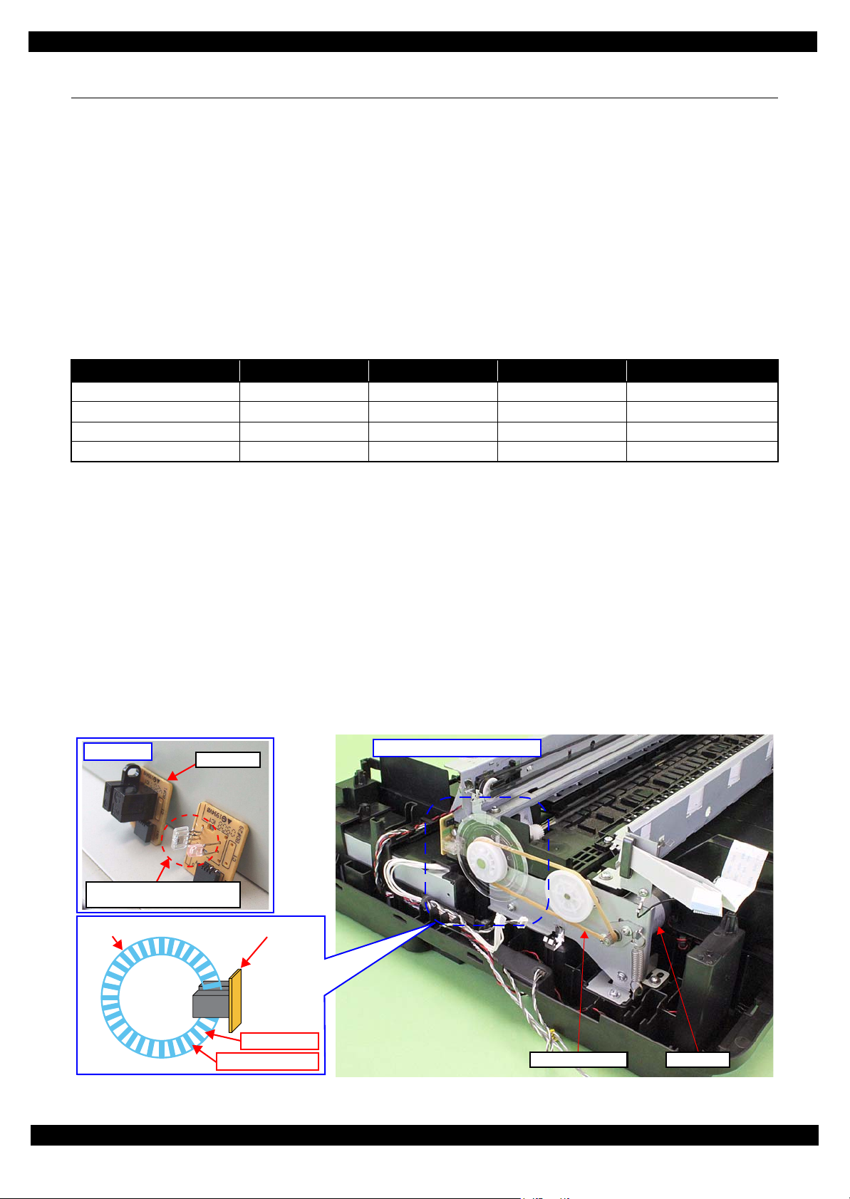
2.2 Motors and Sensors
The following table lists the motors and sensors of WF-7520/7510/7010 series.
Printer Mechanism
Table 2-1. List of Motors & Sensors (Printer Mechanism)
Mechanism Motor or Sensor No.
Printhead ---
Carriage mechanism CR Motor A
CR Encoder 1
PW Sensor 2
Cover Open Sensor 3
Paper loading/feed mechanism PF Motor B
PF Encoder 4
PE Sensor 5
Pre-PE Sensor 6
Paper Stopper Lever Sensor 1st 7
Figure 2-1. Motors & Sensors (Printer Mechanism)
Operating Principles Overview 22
Page 23
Epson WF-7520/7510/7010 series Revision A
2
1
A
2nd cassette (WF-7520/7010 series only)
Table 2-2. List of Motors & Sensors (2nd Cassette)
Mechanism Motor or Sensor No.
Paper loading/feed mechanism Pickup Motor A
Pickup Encoder 1
Paper Stopper Lever Sensor 2nd 2
Figure 2-2. Motors & Sensors (2nd Cassette)
Operating Principles Motors and Sensors 23
Page 24
Epson WF-7520/7510/7010 series Revision A
1
A
A
1
2
3
Scanner (WF-7520/7510 series only)
Table 2-3. List of Motors & Sensors (Scanner)
Mechanism Motor or Sensor No.
Scanner mechanism Scanner Motor Assy A
CIS Unit 1
Figure 2-3. Motors & Sensors (Scanner)
Table 2-4. List of Motors & Sensors (ADF)
Mechanism Motor or Sensor No.
ADF mechanism ADF Motor A
ADF PE Sensor 1
ADF DOC Sensor 2
ADF Encoder 3
Figure 2-4. Motors & Sensors (ADF)
Operating Principles Motors and Sensors 24
Page 25
Epson WF-7520/7510/7010 series Revision A
PF Encoder
With cover
Without cover (light-emitting
and receiving devices)
Left side of Printer Mechanism
PF Encoder
Light passes
Light does not pass
PF Scale
PF Timing Belt PF Motor
2.3 Optical Sensor Control
WF-7520/7510/7010 series uses the optical sensor to control itself. The following describes the operating
principles of optical sensor control.
Control method
To ensure accurate printing, each part must be controlled to make an adequate amount (time) of movement. The
optical sensors read the amount (time) of movements as follows to printer to control it for achieving accurate printing.
1. Rotates the motors for control of the printer, and transmits drive force to the each part via the gear or the
timing belt.
2. The encoder reads the drive amount of each part from the scale one by one to printer to monitor that the part
drives for an adequate amount (time).
Controlled parts
The following table lists where the optical sensor control is used.
Table 2-5. Controlled Parts
Item Motor Scale Encoder Transmission method
PF/ASF (1st cassette) PF Motor PF Scale PF Encoder PF Timing Belt
CR CR Motor CR Scale CR Encoder CR Timing Belt
ASF (2nd cassette*2) Pickup Motor Pickup Scale Pickup Encoder Gear
*3
ADF
Note *1: See Fig. 2-1 (p22) and Fig. 2-2 (p23) for the positions of the parts.
*2: WF-7520/7010 series only
*3: WF-7520/7510 series only
ADF Motor ADF Scale ADF Encoder Gear
Operating principles
The following describes the PF drive control as an example of the actual operation for the optical sensor.
The PF scale consists of light-passing and light-blocking portions on its surface, and runs through the slit between
the encoder’s light-emitting and light-receiving devices. While the printer is operating, the encoder always emits
light from light-emitting device toward the light-receiving device, and the light-receiving device detects light when
the light is transmitted through the light-passing portion of the scale, and does not detect light when the light is
blocked by the light-blocking portion of the scale. According to the counts of light-detected and non detected times,
the printer controls paper feed drive direction and amount.
When the encoder cannot read light-emitting/blocking counts correctly due to the misalignment, broken or
contaminated scale, paper jam, foreign object and increasing a load, the fatal error occurs and the printer stops.
*1
Figure 2-5. PF Drive Control Section
Operating Principles Optical Sensor Control 25
Page 26
Epson WF-7520/7510/7010 series Revision A
%4NQEM %4
130
130
130
130
%4NQEM
KUTGNGCUGF
130
130
130
130
130
130
130
130
130
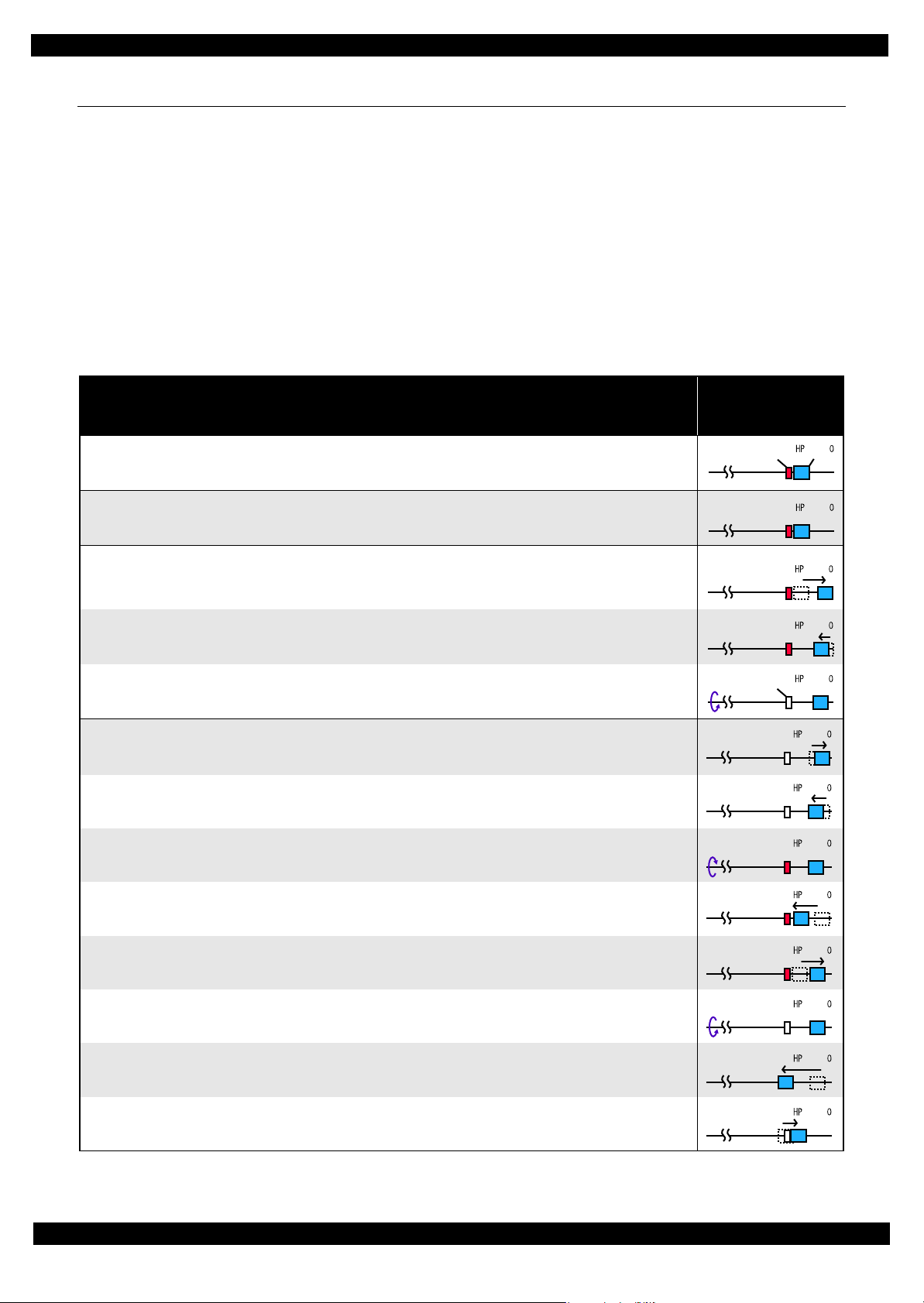
2.4 Power-On Sequence
This section describes the power-on sequences for this product. The preconditions are as follows.
Condition 1: Normal power-on sequence (See Table 2-6.)
Turning on the printer after turning it off without an error.
Initial ink charge has finished and every cartridge has sufficient ink.
No paper on the paper path.
The Printhead is capped with the Cap of the Ink System Assy.
The Carriage is normally fixed by the CR Lock.
Condition 2: Power-on sequence after recovering from a paper jam error (See Table 2-7.)
Turning on the printer after turning it off with a paper jam error.
There still remains paper on the paper path out of the detecting area of the PE sensor.
Table 2-6. Condition 1: Normal Power-on Sequence
Operation
1. Printhead initialization
1-1.Initializes the Printhead, and checks for the fuse on the board in the Printhead.
*2
*4
*1
Carriage/PF Roller
movement and
position
*3
2. Checking for waste ink overflow
2-1.Checks the waste ink counter if the waste ink overflow is occurring.
3. Avoiding deadlock sequence
3-1.The carriage moves to the 0-digit side slowly and confirms it touches the Right Frame.
3-2.The carriage slightly moves to the 130-digit side slowly.
3-3.The PF Motor rotates clockwise, and releases the CR lock.
*5
4. Seeking the home position
4-1.The carriage moves to the 0-digit side slowly and confirms it touches the Right Frame. The position when it
touches the Right Frame is set as the origin position temporarily.
4-2.The carriage slowly moves to the CR lock set position.
4-3.The PF Motor rotates counterclockwise, and sets the CR lock.
4-4.The carriage moves to the 130-digit side slowly and confirms it touches the CR lock.
4-5.The carriage slowly moves toward the 0-digit side and reaches the CR lock set position.
4-6.The PF Motor rotates clockwise, and releases the CR lock.
4-7.The carriage moves to the 130-digit side slowly and confirms it does not touch the CR lock.
4-8.The carriage slowly moves to its home position, and the origin position is fixed.
Afterward, the carriage position is monitored according to the signals from the CR Encoder.
Operating Principles Power-On Sequence 26
Page 27

Epson WF-7520/7510/7010 series Revision A
130
130
130
130
130
130
130
130
130
130
130
130
Table 2-6. Condition 1: Normal Power-on Sequence
Operation
5. PF initialization
5-1.The PF Motor rotates clockwise for approximately one second.
5-2.The PE sensor detects if paper exists
6. Low temperature operation sequence
6-1.The carriage moves back and forth between the CR lock and the 130-digit side for two times.
*6
and the PF Motor rotates clockwise for approximately 0.5 second.
*7
7. PF measurement and PW sensor initialization
7-1.The carriage slowly moves to the 130-digit side.
7-2.The carriage moves to the VHCheck position quickly and stops; meanwhile the voltage values detected by the PW
sensor at the specified three points are recorded. At the same time, the PF Motor rotates clockwise and its load is
measured.
7-3.The carriage detects the voltage of the PW sensor at the carriage stop position (the black area at the Paper Guide
Front).
7-4.The carriage returns near its home position. At the same time, the PF Motor rotates clockwise and its load is
measured.
*2
*1
Carriage/PF Roller
movement and
position
*3
8. Detecting ink cartridge and initializing ink system
8-1.After the carriage slightly moves to the 130-digit side and checks the ink end sensor, detects the ink remaining.
8-2.The carriage slowly returns to its home position.
8-3.The carriage slowly moves to the 0-digit side to the CR lock set position.
8-4.The PF Motor rotates counterclockwise and sets the CR lock.
8-5.The carriage slowly returns to its home position.
*8
Note *1: The PF motor drive is not transmitted to the Pickup Roller during this power-on sequence.
*2: The rotation directions of the PF Motor are as follows.
Clockwise: Paper is fed normally
Counterclockwise: Paper is fed backward
*3: The conditions of the CR lock are as follows.
Red CR lock is set
White CR lock is released
*4: The fatal error occurs if there is a problem such as the fuse blew.
*5: Confirm that the CR lock is not get stuck in the gap of the carriage or any other parts preventing the carriage from moving.
*6: Eject paper if any.
*7: Executed when the detected temperature is under 5 oC (41oF) by the thermistor on the Printhead.
*8: The empty suction operation may occur depending on situations.
Operating Principles Power-On Sequence 27
Page 28

Epson WF-7520/7510/7010 series Revision A
130
130
Table 2-7. Condition 2: Power-on Sequence after Recovering from a Paper Jam Error
Carriage/PF Roller
Operation
Executes No.1 to No.5 on the normal power-on sequence (Table 2-6).
6. Detecting remaining paper
6-1.The carriage moves to the 130-digit side and confirms there is no paper.
6-2.The carriage quickly returns to its home position, and the paper jam error occurs again.
When the user removes the paper and releases the paper jam error by panel operation, the normal power-on sequence from No.1 (Table 2-6) is executed
*2
again.
*1
Note *1: “Paper exists” is detected when the carriage touches the paper. When “paper does not exist” is detected, the power-on sequence
of condition 1 (Table 2-6) is executed from No.6.
*2: If the paper jam error cannot be solved after repeating the power-on sequence on condition 2 (Table 2-7) twice, the printer turns
into the paper jam fatal error for the third time.
movement and
position
Operating Principles Power-On Sequence 28
Page 29

CHAPTER 3
TROUBLESHOOTING
Page 30

Epson WF-7520/7510/7010 series Revision A
3.1 Troubleshooting
In this chapter, the product names are called as follows:
WF-7520 series: Epson WF-7525/Epson WF-7521/Epson WF-7520
WF-7510 series: Epson WF-7515/Epson WF-7511/Epson WF-7510
WF-7010 series: Epson WF-7018/Epson WF-7015/Epson WF-7012/Epson WF-7011/
Epson WF-7010
This section describes the error message list, troubleshooting workflow, fatal error code and FAX
Troubleshooting.
3.1.1 Error Message List
Table 3-1. Error Message List
WF-7010 series WF-7520/7510 series
Status
LED
LCD Message
Power Network Paper Ink
Printer fatal error
Printer fatal error
(paper jam)
Scanner fatal error
Flash at
high speed
Flash at
high speed
*1
--- --- --- ---
Flash at
high speed
Flash at
high speed
Flash at
high speed
Flash at
high speed
Flash at
high speed
Flash at
high speed
Printer error. Turn power off and then on again. For
details, see your documentation or visit Epson.com.
Paper jam inside, in back, or in ADF. Press OK to see
how to remove jammed paper.
Scanner error. Turn power off and then on again. In
the error is not fixed, visit Epson.com for technical
support.
ADF fatal error
ADF paper jam error
Waste ink pad end error Flash
Waste ink pad near end error Flash
Paper jam error Flash
No paper cassette error Flash
Paper out error Flash
Multi-feed error Flash
Paper length mismatch error
for duplex printing
Paper size mismatch error Flash
Incorrect paper size error
Printer/printer driver
mismatch error
*1
*1
*3
*1
--- --- --- --- Automatic Document Feeder (ADF) error.
--- --- --- ---
Alternate
flash 1
Alternate
flash 1
Flash
*2
*2
*2
*2
*2
*2
*2
*2
---
---
--- Flash ---
--- ON --- Load Cassette correctly and press or .
--- ON ---
--- ON ---
--- ON ---
--- ON ---
--- --- --- ---
Flash
*2
---
Flash at
high speed
Alternate
flash 2
Alternate
flash 2
Flash at
high speed
Paper jam in the Automatic Document Feeder
(ADF).
A printer's ink pad is at the end of its service life.
Please contact Epson Support.
A printer's ink pad is nearing the end of its service
life. Please contact Epson Support.
Paper jam. Press OK to see how to remove jammed
paper.
Paper out or paper jam. Check paper size and load
paper in paper cassette.
Multi-page feed error. Remove and reload the paper,
then press or .
Incorrect paper size detected. Load correct paper size
and press or .
No paper source matches paper size setting. Load
appropriate paper in Cassette 1. Press or .
Paper size is incorrect. Load US B 11x17in size plain
paper in Cassette.
Error Press .
Cover open error Flash --- Flash 2 Flash 2 Close the scanner unit.
Ink end error Flash
Ink cartridge detection error Flash
*2
*2
--- --- ON
--- --- ON
You need to replace the following ink cartridge(s).
*4
<Ink Cartridges>XXXXXXX
Cannot recognize the following cartridge(s). Try
*4
installing them again.
<Ink Cartridges>XXXXXXX
*5
*5
Troubleshooting Troubleshooting 30
Page 31

Epson WF-7520/7510/7010 series Revision A
Table 3-1. Error Message List
WF-7010 series WF-7520/7510 series
Status
Power Network Paper Ink
Ink cartridge detection error
(non-Epson cartridge)
No ink cartridge error Flash
Ink cartridge cover open
error
Note : Flash Turns on and off at intervals of 1.25 seconds.
Flash 2 On for 0.5 sec., Off for 0.5 sec., On for 0.5 sec. and Off for 1.0 sec.
Flash at high speed Turns on and off at intervals of 0.5 seconds.
Alternate flash 1 Same as “Flash”
Alternate flash 2 Turns on and off at intervals of 1.25 seconds.
Note *1: WF-7520/7510 series only
*2: Flashes if the status arises when printing starts or when the printer starts up, but lights if the status arises when printing is
complete.
*3: WF-7520/7010 series only
*4: The corresponding ink LED flashes/lights.
*5: The corresponding ink cartridge product number is indicated.
Flash
Flash
*2
*2
*2
LED
--- --- ON
--- --- ON
--- --- ---
LCD Message
Ink cartridge is not recognized. Please replace the
*4
cartridge.
<Ink Cartridges>XXXXXXX
The cartridge is installed incorrectly. Press it down
*4
until it clicks.
<Ink Cartridges>XXXXXXX
The ink cartridge cover is open. Close the ink
cartridge cover.
*5
*5
3.1.2 Troubleshooting Workflow
The following page describes the troubleshooting workflow. Follow the flow when troubleshooting problems.
Troubleshooting Troubleshooting 31
Page 32

Epson WF-7520/7510/7010 series Revision A
Start
Turn on the printer
Does power-on
sequence start?
Yes
Is Power-on sequence
finished without error?
Yes
Standby condition
Perform “Flow A”
What is returned reason?
ADF/Scanner
unit failure
Copy an image
Is scanning operation
finished without
trouble?
Yes
ADF failure?
Yes
Copy an image by ADF
Is ADF operation finished
without trouble?
Yes
*5
Finish
No
No
1
Printer failure only
No
No
No
Major problem without
error message
No Power
[Presumable Cause]
• Power Supply Unit damage
• Main Board damage
[Major Troubleshooting]
• Power Supply Unit
replacement
• Main Board replacement
Scanner failure
[Presumable Cause]
• Contamination of Scanner Glass
• Contamination of Document Pad
• CIS Unit bonding failure
• CIS Unit damage
• Scanner Motor Assy damage
[Major Troubleshooting]
• Scanner Glass cleaning
• Document Pad cleaning
• Document Pad replacement
• CIS Unit replacement
• Scanner Motor Assy replacement
ADF failure
[Phenomenon]
• No paper feed
• Double feed
• Paper jam
• Paper skew
[Presumable Cause]
• Wear of Pickup Roller
• Wear of ADF Pad Assy
• Gear damage
• ADF Motor damage
• Contamination of Scanner Glass
• Paper Sheet damage
• Foreign material
• ADF Paper Guide Upper Assy damage
• Wear of paper eject roller
• ADF Sensor damage
[Major Troubleshooting]
• ADF LD Assy replacement
• ADF Pad Assy replacement
• Scanner Glass cleaning
• Paper Sheet replacement
• Foreign material removal
• ADF Unit replacement
*1
1
Fatal error
Please refer to “ 3.1.3 Fatal Error
Code (p33)” for troubleshooting.
Flow A
Print check pattern
Is printing operation
finished without error?
Is printing operation
finished without trouble?
Return previous flow
Major problem without error message
Poor Printing
[Phenomenon]
• Poor printing quality
• Ink stain on paper
• Dot missing
• Paper eject without printing
[Presumable Cause]
• Driver / Panel mis-setting
• Contamination of CR Scale
• Contamination of Printhead
Cover
• Printhead damage
• Ink clogging of Printhead
• Contamination on Cap / Wiper
of Ink System Assy
• Ink System Assy damage
• Float of Paper Guide Front
Porous Pad
• Narrow PG
• PE Sensor Lever damage
• PE Sensor damage
[Major Troubleshooting]
• Driver / Panel re-setting
• CR Scale replacement
• Printhead Cover cleaning
• Printhead cleaning
• Ink Cartridge replacement
• Printhead replacement
• Rubber cleaning of Cap
• Ink System Assy replacement
• Paper Guide Front Porous Pad
re-installation
• Printer Mechanism (Frame
Base Assy) replacement
• PE Sensor Lever replacement
• PE Sensor replacement
[Occurrence Condition]
[Major Occurrence Timing]
[Troubleshooting]
Start
Yes
Yes
[Presumable Cause]
• Use of 3rd party media
• Edge guide mis-setting
• Foreign material
• Part come-off
• Contamination of paper feed
• Cassette Assy damage
[Major Troubleshooting]
• Recommendation of EPSON
• Edge guide re-setting
• Foreign material removal
• Part re-installation
• Roller replacement
• Cassette Assy replacement
[Presumable Cause]
• Foreign material
• Insufficient grease
• Gear damage
[Major Troubleshooting]
• Foreign material removal
• Lubrication of grease
• Gear replacement
Waste ink pad end error
This error occurs when
maintenance counter in EEPROM
exceeds the specified value.
• Power-on timing
• Print start timing
• Cleaning timing
• Ink Cartridge replacement timing
• Waste Ink Pad (Waste Ink Tray
Assy or Paper Guide Lower
Porous Pad) replacement
• Maintenance counter reset
No
No
Poor Paper Loading
roller in Duplex Unit
media
Abnormal Noise
Ink end error
[Occurrence Condition]
This error occurs when ink in Ink
Cartridge is empty.
[Major Occurrence Timing]
• Power-on timing
• Print start timing
• Cleaning timing
• Ink Cartridge replacement
timing
• During printing
[Troubleshooting]
• Ink Cartridge replacement
[NOTE]
If this error occurs during auto
duplex print operation, printer
stops and eject the paper
automatically even if the printing
is not completed.
Paper jam error
[Occurrence Condition]
This error occurs when the top/
bottom of paper cannot be
detected by PE Sensor within the
specified steps even if the paper
has been fed correctly.
[Major Occurrence Timing]
• Power-on timing
• Paper loading timing
• Paper eject timing
• Auto duplex print timing
[Major Troubleshooting]
1 Press the “OK” button to eject
the paper.
• If succeeded
Starts paper feeding operation
again if printer has print data.
• If failed
Occurs paper jam error again.
2 If fail in the above 1, remove
the paper by opening Scanner
Unit or Printer Cover and
taking off Duplex Unit.
3 Press the “OK” button again.
• If succeeded
Starts paper feeding operation
again if printer has print data.
• If failed
Occurs paper jam error again.
4 Check the following if failed in
Step 3.
• Foreign material
• Part come-off
• PE Sensor Lever
• PE Sensor
• Paper Guide Front Porous
Pad
• Main board
• Paper Stopper Assy
[NOTE]
If this error occurs during auto
duplex print operation, printer
stops and eject the paper
automatically even if the printing
is not completed. (print data of
adverse side & reverse side is
eliminated.)
Major problem with error message
Ink cartridge detection error
[Occurrence Condition]
This error occurs when Ink
Cartridge data is incorrect or Ink
Cartridge is not recognized
correctly.
[Major Occurrence Timing]
• Power-on timing
• Print start timing
• Cleaning timing
• Ink Cartridge replacement
timing
[Major Troubleshooting]
• Remove and reinstall Ink
Cartridge
• Ink Cartridge replacement
• CSIC Terminal replacement
• CR Contact Module
replacement
• Head FFC replacement
• Main Board replacement
Paper out error
[Occurrence Condition]
This error occurs when the top of
paper cannot be detected by PE
Sensor within the specified steps
even if the paper has been fed
correctly. (No paper / paper
loading failed / paper is fed at
slant)
[Major Occurrence Timing]
*4
• Paper loading timing
[Major Troubleshooting]
1 Put papers in Cassette Assy
and press the “OK” button.
2 If a paper stops before reaching
PE Sensor, remove it and
check the paper condition.
3 A) If no damage in the above 2,
set edge guide correctly after
putting papers in
Assy
and retry.
B) If damage in the above 2,
check foreign materials /
parts come-off / parts
transformation in paper path.
4 If the problem is not solved by
3-A & 3-B, check the following.
• Foreign material
• Part come-off
• Surface condition of Pickup
Roller or paper feed roller in
Duplex Unit
• PE Sensor Lever
• PE Sensor
• Pre-PE Sensor Lever
• Pre-PE Sensor
• Main Board
• PF Motor or Pickup Motor
• Cassette Assy
• Paper Stopper Assy
Cassette
No ink cartridge error
[Occurrence Condition]
This error occurs when Ink
Cartridge is not installed.
[Major Occurrence Timing]
• Power-on timing
[Troubleshooting]
• Ink Cartridge installation
Multi-feed error
[Occurrence Condition]
This error occurs on the following
case.
• The top of paper is detected
before the specified steps are
reached.
• Actual paper length is longer
than theoretical one.
[Major Occurrence Timing]
• Paper loading timing
• Paper feed timing
• Paper eject timing
[Troubleshooting]
• PE Sensor Lever replacement
• PE Sensor replacement
• PW Sensor replacement
• Main Board replacement
Cover open error
[Occurrence Condition]
This error occurs when Scanner
Unit or Printer Cover is in open
condition.
[Major Occurrence Timing]
• Power-on timing
[Major Troubleshooting]
• Scanner Unit or Printer Cover
close
• Scanner Unit or Printer Cover
replacement
• Cover Open Sensor
replacement
• Main Board replacement
Paper length mismatch error
for duplex printing
[Occurrence Condition]
This error occurs when actual
paper size is not matched to
theoretical one (both shorter and
longer).
[Major Occurrence Timing]
• Auto duplex print timing
[Troubleshooting]
• PE Sensor Lever replacement
• PE Sensor replacement
• PW Sensor replacement
• Main Board replacement
No paper cassette error
[Occurrence Condition]
This error occurs when Cassette
Assy cannot be detected.
[Major Occurrence Timing]
• Paper loading timing
[Troubleshooting]
• Check connection for Paper
Stopper Lever Sensor cable
• Replace Paper Stopper Lever
Sensor
*2
Paper jam error
Please refer to “ Paper jam error”
of “Error occurs in printing
operation”.
Paper size mismatch error
[Occurrence Condition]
This error occurs when actual
paper size is not matched to
theoretical one. (shorter only)
[Major Occurrence Timing]
• Paper loading timing
*4
• Paper feed timing
• Paper eject timing
[Troubleshooting]
• PE Sensor Lever replacement
• PE Sensor replacement
• PW Sensor replacement
• Main Board replacement
*1: If the printer can turn on but turns off right away, the protection circuit may cut off the power
due to an error such as a circuit failure.
*2: For WF-7010 series, this error occurs only when the Printer Cover is opened.
*3: Only for fax printing for WF-7520/7510 series.
*4: Auto duplex printing is available only for WF-7520/7010 series.
*5: In case of “Not Trouble Found”, check fatal error code.
This flowchart is compiled based on the following contents.
• Our experience regarding the quality problem
• ESK’s repair data
• Printer Mechanism specification for WF-7520/7510/7010 series
WF-7010 series are not equipped with the Scanner / ADF unit,
therefore, the troubleshooting related to the Scanner / ADF unit is
not applied.
*3
Appendix Troubleshooting Workflow 32
Page 33

Epson WF-7520/7510/7010 series Revision A
3.1.3 Fatal Error Code
This section describes the fatal error code and the possible cause for this product.
Printer fatal error list
Table 3-2. Fatal Error List (Printer)
Error type
DC motor
error
Error
code
01H CR PID excess load error
02H CR PID excess speed error
03H CR PID reverse error
04H CR PID lock error
05H CR PID speed degradation error
08H CR load position reverse error
09H CR load position excess speed error
0AH CR load position excess load error
F1H PF PID excess load error
F2H PF PID excess speed error
F3H PF PID reverse error
F4H PF PID lock error
F6H PF PID excess torque limitation error • PF drive mechanism overload (paper jam/foreign object)
Error name Possible cause
• CR Encoder failure (contaminated/detached scale, Encoder Board failure)
• CR Motor failure
• Carriage overload error (paper jam/foreign object)
• Cable disconnection
• CR Encoder failure (contaminated/detached scale, Encoder Board failure)
• Motor driver failure (Main Board failure)
• Tooth skip of the CR Timing Belt
• Improper tension of the CR Timing Belt
• CR Encoder failure (contaminated/detached scale, Encoder Board failure)
• Tooth skip of the CR Timing Belt
• Improper tension of the CR Timing Belt
• Paper jam
• CR Encoder failure (contaminated/detached scale, Encoder Board failure)
• CR Motor failure
• Carriage overload error (paper jam/foreign object)
• Cable disconnection
• CR Encoder failure (contaminated/detached scale, Encoder Board failure)
• Motor driver failure (Main Board failure)
• Tooth skip of the CR Timing Belt
• Improper tension of the CR Timing Belt
• Paper jam
• CR Encoder failure (contaminated/detached scale, Encoder Board failure)
• Tooth skip of the CR Timing Belt
• Improper tension of the CR Timing Belt
• Paper jam
• CR Encoder failure (contaminated/detached scale, Encoder Board failure)
• Motor driver failure (Main Board failure)
• Tooth skip of the CR Timing Belt
• Improper tension of the CR Timing Belt
• CR Encoder failure (contaminated/detached scale, Encoder Board failure)
• CR Motor failure
• Carriage overload error (paper jam/foreign object)
• Cable disconnection
• PF Encoder failure (contaminated/detached scale, Encoder Board failure)
• PF Motor failure
• PF drive mechanism overload (paper jam/foreign object)
• Cable disconnection
• PF Encoder failure (contaminated/detached scale, Encoder Board failure)
• Motor driver failure (Main Board failure)
• Tooth skip of the PF Timing Belt
• Improper tension of the PF Timing Belt
• PF Encoder failure (contaminated/detached scale, Encoder Board failure)
• Tooth skip of the PF Timing Belt
• Improper tension of the PF Timing Belt
• Paper jam
• PF Encoder failure (contaminated/detached scale, Encoder Board failure)
• PF Motor failure
• PF drive mechanism overload (paper jam/foreign object)
• Cable disconnection
Troubleshooting 33
Page 34

Epson WF-7520/7510/7010 series Revision A
Table 3-2. Fatal Error List (Printer)
Error type
DC motor
error
Motor drive
time error
Printhead
system error
Error
code
Error name Possible cause
• PF Encoder failure (contaminated/detached scale, Encoder Board failure)
F8H PF load position reverse error
• Tooth skip of the PF Timing Belt
• Improper tension of the PF Timing Belt
• PF Encoder failure (contaminated/detached scale, Encoder Board failure)
F9H PF load position excess speed error
• Motor driver failure (Main Board failure)
• Tooth skip of the PF Timing Belt
• Improper tension of the PF Timing Belt
FAH PF load position excess load error • PF Encoder failure (contaminated/detached scale, Encoder Board failure)
• PF Motor failure
FCH PF load position error
• PF drive mechanism overload (paper jam/foreign object)
• Cable disconnection
• Pickup Encoder failure (contaminated/detached scale, Encoder Board
failure)
11H ASF PID excess load error
*
• Pickup Motor failure
• Pickup drive mechanism (2nd cassette) overload (paper jam/foreign object)
• Cable disconnection
• Pickup Encoder failure (contaminated/detached scale, Encoder Board
failure)
12H ASF PID excess speed error
*
• Pickup Motor driver failure (Main Board failure)
• Pickup Encoder failure (contaminated/detached scale, Encoder Board
failure)
13H ASF PID reverse error
*
• Paper jam
• Pickup Encoder failure (contaminated/detached scale, Encoder Board
failure)
14H ASF PID lock error
*
• Pickup Motor failure
• Pickup drive mechanism (2nd cassette) overload (paper jam/foreign object)
• Cable disconnection
16H ASF PID excess torque limitation error
18H ASF load position reverse error
*
• Pickup Roller (2nd cassette) overload (paper jam/foreign object)
*
• Pickup Encoder failure (contaminated/detached scale, Encoder Board
failure)
• Paper jam
• Pickup Encoder failure (contaminated/detached scale, Encoder Board
failure)
19H ASF load position excess speed error
*
• Motor driver failure (Main Board failure)
• Pickup Encoder failure (contaminated/detached scale, Encoder Board
failure)
1AH ASF load position excess load error
*
• Pickup Motor failure
• Pickup drive mechanism (2nd cassette) overload (paper jam/foreign
object)
• Cable disconnection
D1H CR (PID) driving time error
D2H CR (load position) driving time error
D3H PF (PID) driving time error
D4H PF (BS) driving time error
D5H ASF (PID) driving time error
D6H ASF (BS) driving time error
*
*
• Main Board failure
40H Transistor temperature error • Main Board failure
41H X-Hot detect error (pre printing)
42H X-Hot detect error (after flushing)
• Printhead failure
• Main Board failure
43H Head temperature error
Troubleshooting 34
Page 35

Epson WF-7520/7510/7010 series Revision A
Table 3-2. Fatal Error List (Printer)
Error type
Sequence
error
Sensor error
Ink device
error
Circuit error 80H Circuit error (include blowout of a fuse) • Main Board failure
Error
code
50H Home position error
51H Deadlock avoidance error
52H Impossible contact detection error
56H
5BH Insoluble paper jam error
60H PW detector error
61H PW detector confusion error
63H PE detector error
B0H -
CFH
Contact error at ink replacement timing
(Power-off)
Ink device error
Error name Possible cause
• Paper jam
• Foreign object
• Deformation of the Main Frame
• Paper jam
• Foreign object
• PW Sensor failure
• Main Board failure
• PW Sensor failure
• Main Board failure
• A piece of paper remaining
• Ink contamination on the Paper Guide Front Assy
• PE Sensor failure
• Main Board failure
• Ink Cartridge failure
• CSIC Terminal failure
• CR Contact Module failure
• Main Board failure
Note *: WF-7520/7010 series only
Troubleshooting 35
Page 36

Epson WF-7520/7510/7010 series Revision A
Scanner/ADF fatal error list (WF-7520/7510 series only)
Table 3-3. Fatal Error List (Scanner/ADF)
Error code Error name Possible cause
01H ADF PID excess speed error
02H ADF PID reverse error
03H ADF PID lock error • ADF Encoder failure (contaminated/detached scale, Encoder Board failure)
04H ADF PID acceleration lock detection error
05H ADF PID excess load error
06H ADF PID driving time error • Main Board failure
09H ADF BS+ excess speed error
0AH ADF BS+ reverse error
0BH ADF BS+ lock error • ADF Encoder failure (contaminated/detached scale, Encoder Board failure)
0DH ADF BS+ excess load error
0EH ADF BS+ driving time error • Main Board failure
10H Scanner HP detection error
20H Scanner LED light error
30H ADF option error • Main Board failure
36H ADF paper jam error • Paper jam
• ADF Encoder failure (contaminated/detached scale, Encoder Board failure)
• Motor driver failure (Main Board failure)
• ADF Encoder failure (contaminated/detached scale, Encoder Board failure)
• Paper jam
• ADF Motor failure
• ADF drive overload (paper jam/foreign object)
• Cable disconnection
• ADF Encoder failure (contaminated/detached scale, Encoder Board failure)
• Motor driver failure (Main Board failure)
• ADF Encoder failure (contaminated/detached scale, Encoder Board failure)
• Paper jam
• ADF Motor failure
• ADF drive overload (paper jam/foreign object)
• Cable disconnection
• CIS Unit failure
• Scanner Housing failure
• Main Board failure
• CIS Unit failure
• Main Board failure
Troubleshooting 36
Page 37

Epson WF-7520/7510/7010 series Revision A
Item Information
Communication start
date / time
Year/month/day/hour/minute
Communication type Sending/receiving/polling reception
Communication ID
Sending/polling reception:
• Destination name of speed dial (first 20 characters)
• Telephone number (last 20 characters)
• Destination fax ID (20 characters)
Receiving:
• Destination fax ID (20 characters)
Airtime Hour/minute/second
Communication pages 0 to 100
Communication result
Common:
Normal/cancel/error code
*
Sending/polling reception:
No dial tone detected/No fax signal detected/Busy tone detected
3.1.4 FAX Troubleshooting (WF-7520/7510 series only)
3.1.4.1 FAX Log
When an error related to fax occurs, it is not only indicated on the LCD but also saved as a log file. The error
code is recorded in it, and according to this log, the contents of the error can be confirmed.
Table 3-4. FAX Log (1)
Log Name Description Save Destination
Latest log
(Last Transaction)
*1
The latest communication log of sending / polling reception Nonvolatile memory
The following information is stored.
Communication log
(Fax Log)
Note *: For error codes, see Table 3-6. Error Code List (p.38).
Power failure log
(Fax Log)
Note *1 : The latest communication log for all destinations are printed in a list form when the sequential broadcast is executed. Cancellation is treated as
*2: The power failure log when the sequential broadcast is being executed is not printed for the destinations to which the transmission log is already
*2
a normal termination, therefore, if it is cancelled, the latest log is printed when the auto print setting is “always print”, and not printed when the
setting is “only when an error occurs”. If “only when an error occurs” is selected, the log is printed even when an error occurs for just one
destination.
complete then. If the power failure occurs before the scheduled sending time when a broadcast is scheduled, the scheduled sending time is
recorded.
The information stored in this log is the same as the communication log. However, since the
airtime is “Unknown” in this case, the result of it is recorded as “power failure”.
Nonvolatile memory
Nonvolatile memory
The communication log is not stored under the following conditions:
When the sending operation is canceled while storing B&W image or waiting for
redialing.
In the case of a power failure during the operation of sending/polling reception including
waiting status for redial, or during receive operation.
When the receiving operation is canceled before the fax signal is detected.
If the fax signal is not detected during receiving operation.
If cancelled during the sequential broadcast.
Troubleshooting 37
(The log for the destinations of “not dialed yet” or “waiting for re-dial” is not saved except
for those of which the communication is complete.)
Page 38

Epson WF-7520/7510/7010 series Revision A
Item Information
Communication start
date / time
Year/month/day/hour/minute
Communication type Sending/receiving/polling reception
Communication ID
Sending/polling reception:
• Destination name of speed dial (first 20 characters)
• Telephone number (last 20 characters)
• Destination fax ID (20 characters)
Receiving:
• Destination fax ID (20 characters)
Airtime Hour/minute/second
Communication pages 0 to 100
Communication result
Common:
Normal/cancel/error code
Sending/polling reception:
No dial tone detected/No fax signal detected/Busy tone detected
Diagnosing code
10 bytes
Protocol data
The latest 43 commands/responses*
• Time stamp
• Sending / receiving
• Command /response code
(See Table 3-7. Command/Response Code (p.40))
• FCF/FIF (first 33 octets).
Table 3-5. FAX Log (2)
Log Name Description Save Destination
The following information of the latest communication is stored.
Protocol trace
Note *: If a large amount of FIF is received, the recorded command/response may be less than
40.
Volatile memory
Error codes
Table 3-6. Error Code List
Error
Code
(HEX)
000 Successful completion (Monochrome) Complete OK
C000 Successful completion (Color) Complete OK Color
400 Communication error Communication error Error code
401 Communication error Communication error Error code
402 Communication error Communication error Error code
403 Communication error Communication error Error code
404 Communication error Communication error Error code
Troubleshooting 38
405 Communication error Communication error Error code
407 Communication error Communication error Error code
408 Communication error Communication error Error code
409 Communication error Communication error Error code
410 Communication error Communication error Error code
412 Communication error Communication error Error code
416 Communication error Communication error Error code
417 Communication error Communication error Error code
418 Communication error Communication error Error code
420
421 Communication error Communication error Error code
422 Communication error Communication error Error code
427 Communication error Communication error Error code
433 Communication error Communication error Error code
Fax signal was not detected during receive operation. (The call was a
telephone call)
Phenomenon LCD Display Print Example
Not displayed ---
Page 39

Epson WF-7520/7510/7010 series Revision A
Table 3-6. Error Code List
Error
Code
(HEX)
434 Communication error Communication error Error code
436 Communication error Communication error Error code
459 Communication error Communication error Error code
490 Communication error Communication error Error code
494 Communication error Communication error Error code
495 Communication error Communication error Error code
496 Communication error Communication error Error code
501 Communication error Communication error Error code
502 Communication error Communication error Error code
503 Communication error Communication error Error code
504 Communication error Communication error Error code
505 Communication error Communication error Error code
540 Communication error Communication error Error code
541 Communication error Communication error Error code
542 Communication error Communication error Error code
543 Communication error Communication error Error code
544 Communication error Communication error Error code
550 Communication error Communication error Error code
554 Communication error Communication error Error code
620 Communication error Communication error Error code
621 Communication error Communication error Error code
623 Communication error Communication error Error code
624 Communication error Communication error Error code
630 A busy tone was detected after dialing
631 Communication error Communication error Error code
632 Communication error Communication error Error code
633 Communication error Communication error Error code
634 A fax signal was not detected for a given length of time after dialing No Answer No Answer
637 A dial tone was not detected before dialing No Dial Tone No Dial Tone
638 A power failure occurred during communication Not displayed Power Fail
700 The communication was canceled by an operation Canceled Canceled
706 System error System Error Error code
709 Communication error Communication error Error code
815 Communication error Communication error Error code
870 The image memory is full Memory Full Memory Full
871 The maximum number of files was exceeded Error code Error code
873 Communication error Communication error Error code
874 Communication error Communication error Error code
875 Communication error Communication error Error code
880 System error System Error Error code
881 System error System Error Error code
882 System error System Error Error code
883 System error System Error Error code
884 System error System Error Error code
928 Collision (A call signal was detected when shifting to dial operation) Not displayed ---
F0B Communication error Communication error Error code
F1E Communication error Communication error Error code
F20 Communication error Communication error Error code
F21 System error System Error Error code
Phenomenon LCD Display Print Example
Talking
(Line Busy)
Talking
(Line Busy)
Troubleshooting 39
Page 40

Epson WF-7520/7510/7010 series Revision A
Table 3-6. Error Code List
Error
Code
(HEX)
F23 Communication error Communication error Error code
F24 Communication error Communication error Error code
F25 Communication error Communication error Error code
F27 System error System Error Error code
F28 System error System Error Error code
F29 Communication error Communication error Error code
F2A Communication error Communication error Error code
F2B No image data for reprint exists No Image ---
F2F System error System Error Error code
F3A Communication error Communication error Error code
F51 System error System Error Error code
F57 Communication error Communication error Error code
F58 Communication error Communication error Error code
F59 System error System Error Error code
F60 A scanner fatal error occurs
F61 A printer fatal error occurs
F62 Reserved --- Error code
F63 ADF misfeed or paper jam occurred
F64 The memory for printing received image is full Error code Error code
Note *: Confirm the fatal error code with the Adjustment Program to check which error occurred. (See " 3.1.3 Fatal Error Code (p33)".)
Phenomenon LCD Display Print Example
Same message when a scanner
fatal error occurred
Same message when a printer
fatal error occurred
Same message when an ADF
fatal error occurred
*
*
*
Error code
Error code
ADF Jam
Command/response code
Table 3-7. Command/Response Code
Command/response
code
DIS 80 - Digital Identification Signal
CSI 40 - Called Subscriber Identification
NSF 20 - Non-Standard Facilities
DTC 81 - Digital Transmit Command
CIG 41 - CallInG subscriber identification
NSC 21 - Non-Standard facilities Command
PWD C1 - PassWorD
SEP A1 - Selective Polling
Reserved (PSA) 61 - Polled SubAddress
Reserved (CIA) E1 - Calling subscriber Internet Address
Reserved (ISP) 11 - Internet Selective Polling address
DCS 82 - Digital Command Signal
TSI 42 - Transmitting Subscriber Identification
NSS 22 - Non-Standard facilities Set-up
SUB C2 - SUBaddress
SID A2 - Sender IDentification
TRN E6 - Training
TCF F0 - Training Check
CTC 12 - Continue To Correct
Reserved (TSA) 62 - Transmitting Subscriber internet Address
Reserved (IRA) E2 - Internet Routing Address
CFR 84 - ConFirmation to Receive
FCF value (HEX)
(LSB first: X=0)
First Second
Content
Troubleshooting 40
Page 41

Epson WF-7520/7510/7010 series Revision A
Table 3-7. Command/Response Code
Command/response
code
FTT 44 - Failure To Train
CTR C4 - Response for Continue To correct
Reserved (CSA) 24 - Called Subscriber internet Address
EOM 8E - End Of Message
MPS 4E - MultiPage Signal
EOP 2E - End Of Procedure
PRI-EOM 9E - Procedure Interrupt-End Of Message
PRI-MPS 5E - Procedure Interrupt-MultiPage Signal
PRI-EOP 3E - Procedure Interrupt-End Of Procedure
Reserved (EOS) 1E - End Of Selection
PPS-EOM BE 8E Partial Page Signal-End Of Message
PPS-MPS BE 4E Partial Page Signal-MultiPage Signal
PPS-EOP BE 2E Partial Page Signal-End Of Procedure
PPS-PRI-EOM BE 9E Partial Page Signal-Procedure Interrupt- End Of Message
PPS-PRI-MPS BE 5E Partial Page Signal-Procedure Interrupt- MultiPage Signal
PPS-PRI-EOP BE 3E Partial Page Signal-Procedure Interrupt- End Of Procedure
PPS-EOS BE 1E Partial Page Signal-End Of Selection
PPS-NULL BE 00 Partial Page Signal-partial page boundary
EOR-EOM CE 8E End Of Retransmission-End Of Message
EOR-MPS CE 4E End Of Retransmission-MultiPage Signal
EOR-EOP CE 2E End Of Retransmission-End Of Procedure
EOR-PRI-EOM CE 9E End Of Retransmission-Procedure Interrupt-End Of Message
EOR-PRI-MPS CE 5E End Of Retransmission-Procedure Interrupt-MultiPage Signal
EOR-PRI-EOP CE 3E End Of Retransmission-Procedure Interrupt-End Of Procedure
EOR-EOS CE 1E End Of Retransmission-End Of Selection
EOR-NULL CE 00 End Of Retransmission- partial page boundary
RR 6E - Receive Ready
MCF 8C - Message ConFirmation
RTP CC - ReTrain Positive
RTN 4C - ReTrain Negative
PIP AC - Procedure Interrupt Positive
PIN 2C - Procedure Interrupt Negative
PPR BC - Partial Page Request
RNR EC - Receive Not Ready
ERR 1C - Response for End of Retransmission
Reserved (FDM) FC - File Diagnostic Message
DCN FA - DisCoNnect
CRP 1A - Command RePeat
Reserved (FNV) CA - Field Not Valid
PIX FF - PIXel image
Space Other combinations Unknown command/response
FCF value (HEX)
(LSB first: X=0)
First Second
Content
Troubleshooting 41
Page 42

Epson WF-7520/7510/7010 series Revision A
3.1.4.2 Error Code/Superficial Phenomenon-Based Troubleshooting
This section explains the troubleshooting procedures based on the error codes and superficial phenomenon.
When an error occurs, it may be displayed on the LCD panel with a message instead of
an error code. To check the error code, print out a fax log.
If the problem is not solved even after carrying out the remedy shown in the Table 3-8,
print out a protocol trace to analyze the cause of the error.
Table 3-8. Troubleshooting Based on the Error Code/Superficial Phenomenon
Error code (LCD
Message)/Phenomenon
Communication Error
(The error is indicated with
error code on the fax log.)
Line Busy The line is busy. Try again later.
No answer
Power fail
706,880-884,F21,F27F28,F2F,F51,F59
Memory full Out of Memory
871
F60 A scanner fatal error occurred
F61 A printer fatal error occurred
F62 Reserved ---
F63
F64
Cannot receive faxes
Cannot dial
Cannot receive/send faxes
in color
Communication error
The other end of the line does not
answer.
The other end of the line
answered but no answer tone is
detected.
Power failure occurred during
sending/receiving/printing/
redialing.
A system error (fax circuit failure)
occurs
Maximum number of files is
exceeded
ADF document mis-feed or paper
jam occurs
The memory for printing received
image is full
The telephone cable is not
connected properly.
The telephone line is not working. Verify if the phone line works by connecting to a phone to it.
Auto answer is set to “N”. Set to “Y”.
DRD setting is incorrect.
Calling signal cannot be detected.
The telephone cable is not
connected properly.
The telephone line is not working. Verify if the phone line works by connecting to a phone to it.
Pulse/Tone dial setting error Turn the setting to the other one and try again.
ECM is set to off. Set to on and try again.
Fax mode is set to “B&W only”. Set to “B&W/Color”.
Description Remedy
Turn off v.34 and try again.
Turn off ECM and try again.
When using xDSL, check the connection from “Line” jack to the fax
via the xDSL splitter.
When using TAM, check the connection from “Line” jack to the
TAM via the fax.
Check if the telephone line makes any sounds.
Check the number and dial again.
Confirm the P/S Board Connector Cable or P/S Board is not
damaged, and retry.
Replace the FAX board with a new one.
Ask the sender to resend the fax in several batches.
• See Table 3-2 " Fatal Error List (Printer) " (p.33).
• See Table 3-3 " Fatal Error List (Scanner/ADF) " (p.36).
• Set the documents and try again.
• If a paper jam error occurs, remove the jammed paper and try
again.
Ask the sender to resend the fax in several batches.
Connect the telephone cable properly.
Set the setting to “ALL” and try again. Should other ring patterns be
selected, contact the telephone company.
Contact the telephone company or obtain the fax log for more
analysis.
Connect the telephone cable properly.
Troubleshooting 42
Page 43

Epson WF-7520/7510/7010 series Revision A
Table 3-8. Troubleshooting Based on the Error Code/Superficial Phenomenon
Error code (LCD
Message)/Phenomenon
Cannot print all the
received data when
printing data stored in
memory
Images run off the paper
The size of the memory is 2.0
Mbyte. If the data becomes over
the set threshold, oldest data are
deleted to make room for new
ones.
Auto reduction is set to off. Set auto reduction to on and reprint the data.
Paper size setting does not match
the size of the received data.
Paper size setting does not match
the size of papers in the tray.
Description Remedy
Ask the sender to resend the data if necessary because the data
deleted from the memory can not be restored.
Choose the correct setting and reprint the data.
Choose the correct setting or load correct sized papers in the tray and
reprint the data.
Troubleshooting 43
Page 44

CHAPTER 4
DISASSEMBLY/REASSEMBLY
Page 45

Epson WF-7520/7510/7010 series Revision A
4.1 Overview
In this chapter, the product names are called as follows:
WF-7520 series: Epson WF-7525/Epson WF-7521/Epson WF-7520
WF-7510 series: Epson WF-7515/Epson WF-7511/Epson WF-7510
WF-7010 series: Epson WF-7018/Epson WF-7015/Epson WF-7012/Epson WF-7011/
Epson WF-7010
This chapter describes procedures for disassembling the main parts/units of WF-7520/7510/7010 series. Unless
otherwise specified, disassembled parts/units can be reassembled by reversing the disassembly procedure. See
the cautions or tips for disassembly/reassembly described in "4.3 Detailed Disassembly/Reassembly Procedure
for each Part/Unit (p55)".
Read the "Safety Precautions (p3)" before disassembling and reassembling.
When you have to remove units or parts that are not described in this chapter, see the exploded diagrams of SPI
(Service Parts Information).
4.1.1 Tools
Use only specified tools to avoid damaging the printer.
Name Availability EPSON Part Code
(+) Phillips screwdriver #1 O 1080530
(+) Phillips screwdriver #2 O ---
Flathead screwdriver O ---
Flathead Precision screwdriver #1 O ---
Tweezers O ---
Longnose pliers O ---
Acetate tape --- 1003963
Nippers O ---
Note 1: Some of the tools listed above are commercially available.
2: EPSON provides the tools listed with EPSON part code.
4.1.2 Jigs
Name Quantity EPSON Part Code
Thickness gauge (1.5 mm) 2 Commercially available
Thickness gauge (1.9 mm) 2 Commercially available
Sonic tension gauge 1 1294120
Disassembly/Reassembly Overview 45
Page 46

Epson WF-7520/7510/7010 series Revision A
4.2 Disassembly/Reassembly Procedures
4.2.1 Parts/Units Need to be Removed in Advance
In "4.2.2 Disassembling Flowchart (p48)", the procedures are indicated on the premise that some parts/units are
removed in advance. Make sure to remove the following parts/units before starting disassembly.
Cassette Assy 1st / 2nd
Duplex Unit
Figure 4-1. Removing the Cassette Assy 1st/2nd
Figure 4-2. Removing the Duplex Unit
Disassembly/Reassembly Disassembly/Reassembly Procedures 46
Page 47

Epson WF-7520/7510/7010 series Revision A
USB Cover
1
2
(p 15) (p 20)
Ink System Assy
1
1
(p 16) (p 40)
Item Description Reference
Parts/unit name
White-letter Part/unit supplied as an ASP ---
Black-letter Part/unit not supplied as an ASP ---
Icon
Indicates a practice or condition that could result in
injury or loss of life if not strictly observed.
Indicates the reference
page in blue-letter
Indicates a practice or condition that could result in
damage to, or destruction of equipment if not strictly
observed.
Indicates the reference
page in blue-letter
Indicates the parts that are inevitably broken in the
disassembling procedure, and should be replaced with
a new one for reassembly.
Indicates the reference
page in blue-letter
Indicates necessary check items in the disassembling/
assembling procedure.
Indicates the reference
page in blue-letter
Indicates supplementary explanation for disassembly
is given.
Indicates the reference
page in blue-letter
Indicates particular tasks to keep quality of the units
are required.
Indicates the reference
page in blue-letter
Indicates particular routing of cables is required.
Indicates the reference
page in blue-letter
Indicates particular adjustment(s) is/are required.
Chapter 5 "Adjustment
(p68)"
Indicates lubrication is required.
Chapter 6 "Maintenance
(p79)"
Indicates the number of screws securing the parts/
units.
---
Indicates the points secured with other than a screw
such as a hook, rib, dowel or the like.
---
Shows removal/installation
as a unit/assy. is available.
Reference page
Shows the screw types and
the specified torque in the
“Screw type/torque list”.
White letters indicate a part/
unit supplied as an ASP.
Black letters indicate a part/
unit not supplied as an ASP.
This section describes procedures for disassembling the parts/units in a flowchart format. For some parts/units,
detailed procedures or precautions are provided (accordingly indicated by icons and cell's color). Refer to the
explanations in the example chart below and perform an appropriate disassembling and assembling procedure.
(See "4.3 Detailed Disassembly/Reassembly Procedure for each Part/Unit (p55) ".)
For routing cables, see "4.4 Routing FFCs/cables (p63)".
The example below shows how to see the charts on the following pages.
S4
S3
Disassembly/Reassembly Disassembly/Reassembly Procedures 47
Page 48

Epson WF-7520/7510/7010 series Revision A
4.2.2 Disassembling Flowchart
4.2.2.1 Exterior Parts
WF-7520 series
A
(p 49)
WF-7510 series
A
(p 49)
Lower Case
S2
(p 56)
Paper Stopper
Assy 2nd
Pickup Assy 2nd
S2
(p 55)
Lower Case
S2
(p 56)
Waste Ink Tray
Cover
6
4
S1
1
2
(p 55)
Paper Stopper
Assy 2nd
S7
(p 59) (p 79)
Foot
2
---
---
---
---
Waste Ink Tray
Assy
1
(p 68)
4
S1
(p 55)
1
2
Common parts/unit
WF-7520/7010 series specific
Waste Ink Tray
Assy
6
4
(p 55)
S1
(p 68)
1
4
Paper Stopper
Assy 1st
S3
(p 59) (p 79)
Foot
2
---
---
---
---
Screw type/torque list
Symbol Screw type Torque
S1
C.B.P-TITE SCREW 3x10 F/ZB-3C 6 ± 1 kgf·cm
S2
C.B.P-TITE SCREW 3x10 F/ZN-3C 6 ± 1 kgf·cm
S3
C.B.P-TITE SCREW 3x8 F/ZN-3C 6 ± 1 kgf·cm
S4
C.B.P-TITE SCREW 2x8 F/ZN-3C 2 ± 0.5 kgf·cm
S5
C.B.P-TITE SCREW 2.5x8 F/ZN-3C 4 ± 1 kgf·cm
S6
C.B.P-TITE SCREW 3x10 F/ZN-3C 8 ± 1 kgf·cm
S7
C.B.P-TITE SCREW 3x8 F/ZN-3C 8 ± 1 kgf·cm
S8
C.B.P-TITE (S-P1) SCREW 3x12 F/ZN-3C 5.5 ± 0.5 kgf·cm
S9
C.B.S-TITE SCREW 3x6 F/ZN-3C 6 ± 1 kgf·cm
S10
C.B.S-TITE SCREW 3x10 F/ZN-3C 6 ± 1 kgf·cm
S11
C.P.SCREW 2.5x6 F/ZN-3C 2 ± 0.5 kgf·cm
S12
C.P.SCREW 3x4 F/ZN-3C 2 ± 0.5 kgf·cm
S13
C.P.SCREW 3x6 F/ZN-3C 6 ± 1 kgf·cm
S14
C.B.P-TITE (S-P1) SCREW 3x12 F/ZN-3C 6 ± 1 kgf·cm
S15
C.P.SCREW 3x4 F/ZN-3C 6 ± 1 kgf·cm
S16
C.B.S-TITE SCREW 3x6 F/ZB-3C 6 ± 1 kgf·cm
S17
C.B.P-TITE SCREW 3x8 F/ZN-3C 5.5 ± 0.5 kgf·cm
S18
C.B.P-TITE SCREW 2.6x5 F/ZN-3C 2 ± 0.5 kgf·cm
S19
C.B.P-TITE SCREW 3x6 F/ZN-3C 6 ± 1 kgf·cm
S20
C.B.P-TITE SCREW 3x8 F/ZN-3C 5 ± 1 kgf·cm
parts/unit
Flowchart 4-1. Disassembling Flowchart (1)
Disassembly/Reassembly Disassembling Flowchart 48
Page 49

Epson WF-7520/7510/7010 series Revision A
WF-7520/7510 series
A
(p 48)
USB Cover
S1
(p 55)
ADF Unit/
Scanner Unit
S14
(p 64)
Hinge
S2
---
Decoration Plate
Housing Right
Housing Left
Housing Upper
Assy (w/ Panel
Unit)
S2
(p 55) (p 63)
B
(p 52)
ADF Pad Assy
2
7
---
4
(p 57)
4
---
Ferrite Core
---
Document Pad
(p 56)
1
(p 50)
Decoration Plate
---
---
S2S1
---
Housing Right
(p 55)
6
2
Housing Left
---
18
(p 55)
---
19
Paper Sheet
Holder
---
3
---
Paper Sheet
---
2
---
ADF Paper Guide
Upper Assy
(p 57)
---
2
ADF Cover
S3
(p 58)
4
---
---
---
Panel Unit
2
3
---
S2
(p 56) (p 63)
4
---
Cover Open
Sensor
5
Panel Lever
Spacer
---
---
(p 62)
Panel Gear /
Panel Lever
---
4
---
Panel Board
S2
(p 56)
LCD Unit
S4
(p 56)
4
4
2
2
---
(p 63)
Panel Unit
Housing Upper
---
---
---
2
Panel Housing
Lower
6
S2
---
(p 56)
Panel FFC
---
---
(p 63)
Panel Housing
Upper Assy
---
---
(p 62)
LD Shaft
(p 79)
Extension Spring
1.69
---
ADF LD Assy
(p 58)
---
1
---
Screw type/torque list
2
Symbol Screw type Torque
S1
S2
S3
S4
---
2
S5
S6
S7
S8
S9
S10
S11
S12
S13
S14
S15
S16
S17
S18
S19
S20
Common parts/unit
WF-7520/7510 series
specific parts/unit
C.B.P-TITE SCREW 3x10 F/ZB-3C 6 ± 1 kgf·cm
C.B.P-TITE SCREW 3x10 F/ZN-3C 6 ± 1 kgf·cm
C.B.P-TITE SCREW 3x8 F/ZN-3C 6 ± 1 kgf·cm
C.B.P-TITE SCREW 2x8 F/ZN-3C 2 ± 0.5 kgf·cm
C.B.P-TITE SCREW 2.5x8 F/ZN-3C 4 ± 1 kgf·cm
C.B.P-TITE SCREW 3x10 F/ZN-3C 8 ± 1 kgf·cm
C.B.P-TITE SCREW 3x8 F/ZN-3C 8 ± 1 kgf·cm
C.B.P-TITE (S-P1) SCREW 3x12 F/ZN-3C 5.5 ± 0.5 kgf·cm
C.B.S-TITE SCREW 3x6 F/ZN-3C 6 ± 1 kgf·cm
C.B.S-TITE SCREW 3x10 F/ZN-3C 6 ± 1 kgf·cm
C.P.SCREW 2.5x6 F/ZN-3C 2 ± 0.5 kgf·cm
C.P.SCREW 3x4 F/ZN-3C 2 ± 0.5 kgf·cm
C.P.SCREW 3x6 F/ZN-3C 6 ± 1 kgf·cm
C.B.P-TITE (S-P1) SCREW 3x12 F/ZN-3C 6 ± 1 kgf·cm
C.P.SCREW 3x4 F/ZN-3C 6 ± 1 kgf·cm
C.B.S-TITE SCREW 3x6 F/ZB-3C 6 ± 1 kgf·cm
C.B.P-TITE SCREW 3x8 F/ZN-3C 5.5 ± 0.5 kgf·cm
C.B.P-TITE SCREW 2.6x5 F/ZN-3C 2 ± 0.5 kgf·cm
C.B.P-TITE SCREW 3x6 F/ZN-3C 6 ± 1 kgf·cm
C.B.P-TITE SCREW 3x8 F/ZN-3C 5 ± 1 kgf·cm
Flowchart 4-2. Disassembling Flowchart (2)
Disassembly/Reassembly Disassembling Flowchart 49
Page 50

Epson WF-7520/7510/7010 series Revision A
WF-7520/7510 series
(p 49)
1
ADF Unit
(p 57)
Scanner Unit
---
3
ADF Paper Guide
Upper Assy
ADF Stacker
Cover
---
---
ADF Right
Cover
---
(p 57)
2
---
4
Scanner Housing
Upper Assy
10
S1 S2
---
(p 62)
8
(p 57)
ADF Front
Cover
(p 57)
---
11
ADF Rear Cover
S2
(p 57)
ADF Base Cover
2
8
Scanner Carriage
---
2
(p 62) (p 66)
CIS Module
---
2
---
Scanner FFC
Cover
(p 62) (p 66)
---
2
(p 79)
---
ADF Document
Support
(p 57)
8
---
(p 57)
2
ADF Housing
Lower Assy
---
---
---
Scanner Motor
Assy
S14
(p 62) (p 66)
(p 79)
---
WF-7520/7510 series
specific p ar ts/un it
2
Screw type/torque list
Symbol Screw type Torque
S1
C.B.P-TITE SCREW 3x10 F/ZB-3C 6 ± 1 kgf·cm
S2
C.B.P-TITE SCREW 3x10 F/ZN-3C 6 ± 1 kgf·cm
S3
C.B.P-TITE SCREW 3x8 F/ZN-3C 6 ± 1 kgf·cm
S4
C.B.P-TITE SCREW 2x8 F/ZN-3C 2 ± 0.5 kgf·cm
S5
C.B.P-TITE SCREW 2.5x8 F/ZN-3C 4 ± 1 kgf·cm
S6
C.B.P-TITE SCREW 3x10 F/ZN-3C 8 ± 1 kgf·cm
S7
C.B.P-TITE SCREW 3x8 F/ZN-3C 8 ± 1 kgf·cm
S8
C.B.P-TITE (S-P1) SCREW 3x12 F/ZN-3C 5.5 ± 0.5 kgf·cm
S9
C.B.S-TITE SCREW 3x6 F/ZN-3C 6 ± 1 kgf·cm
S10
C.B.S-TITE SCREW 3x10 F/ZN-3C 6 ± 1 kgf·cm
S11
C.P.SCREW 2.5x6 F/ZN-3C 2 ± 0.5 kgf·cm
S12
C.P.SCREW 3x4 F/ZN-3C 2 ± 0.5 kgf·cm
S13
C.P.SCREW 3x6 F/ZN-3C 6 ± 1 kgf·cm
S14
C.B.P-TITE (S-P1) SCREW 3x12 F/ZN-3C 6 ± 1 kgf·cm
S15
C.P.SCREW 3x4 F/ZN-3C 6 ± 1 kgf·cm
S16
C.B.S-TITE SCREW 3x6 F/ZB-3C 6 ± 1 kgf·cm
S17
C.B.P-TITE SCREW 3x8 F/ZN-3C 5.5 ± 0.5 kgf·cm
S18
C.B.P-TITE SCREW 2.6x5 F/ZN-3C 2 ± 0.5 kgf·cm
S19
C.B.P-TITE SCREW 3x6 F/ZN-3C 6 ± 1 kgf·cm
S20
C.B.P-TITE SCREW 3x8 F/ZN-3C 5 ± 1 kgf·cm
Flowchart 4-3. Disassembling Flowchart (3)
Disassembly/Reassembly Disassembling Flowchart 50
Page 51

Epson WF-7520/7510/7010 series Revision A
WF-7010 series
USB Cover
(p 55)
Decoration Plate
Panel Unit
Screw Cover Left/
Right
Housing Upper
Assy (w/ Printer
Cover)
S2
(p 63)
B
(p 52)
---
---
Decoration Plate
---
6
4
(p 56)
Printer Cover
---
3
---
Screw Cover Left/
Right
---
1
---
Panel Unit
---
2
(p 56)
Panel Board
S3
---
3
---
Panel Housing
Upper Assy
---
---
---
Cover Open
Sensor Cover
---
Cover Open
Sensor
(p 63)
Lower Case
---
2
S2
(p 56)
Paper Stopper
Assy 2nd
6
4
---
2
Pickup Assy 2nd
1
S2
2
(p 55)
Waste Ink Tray
Cover
S1
(p 55)
Waste Ink Tray
Assy
S1
(p 55)
(p 68)
Paper Stopper
Assy 2nd
1
2
S7
2
---
(p 59) (p 79)
Foot
---
---
---
1
4
Common parts/unit
WF-7520/7010 ser ies specific
parts/unit
4
WF-7010 ser ies specific pa r t s/
unit
Screw type/torque list
Printer Cover
Housing Upper
---
---
---
Panel FFC
---
---
(p 63)
Symbol Screw type Torque
S1
C.B.P-TITE SCREW 3x10 F/ZB-3C 6 ± 1 kgf·cm
S2
C.B.P-TITE SCREW 3x10 F/ZN-3C 6 ± 1 kgf·cm
S3
C.B.P-TITE SCREW 3x8 F/ZN-3C 6 ± 1 kgf·cm
S4
C.B.P-TITE SCREW 2x8 F/ZN-3C 2 ± 0.5 kgf·cm
S5
C.B.P-TITE SCREW 2.5x8 F/ZN-3C 4 ± 1 kgf·cm
S6
C.B.P-TITE SCREW 3x10 F/ZN-3C 8 ± 1 kgf·cm
S7
C.B.P-TITE SCREW 3x8 F/ZN-3C 8 ± 1 kgf·cm
S8
C.B.P-TITE (S-P1) SCREW 3x12 F/ZN-3C 5.5 ± 0.5 kgf·cm
S9
C.B.S-TITE SCREW 3x6 F/ZN-3C 6 ± 1 kgf·cm
S10
C.B.S-TITE SCREW 3x10 F/ZN-3C 6 ± 1 kgf·cm
S11
C.P.SCREW 2.5x6 F/ZN-3C 2 ± 0.5 kgf·cm
S12
C.P.SCREW 3x4 F/ZN-3C 2 ± 0.5 kgf·cm
S13
C.P.SCREW 3x6 F/ZN-3C 6 ± 1 kgf·cm
S14
C.B.P-TITE (S-P1) SCREW 3x12 F/ZN-3C 6 ± 1 kgf·cm
S15
C.P.SCREW 3x4 F/ZN-3C 6 ± 1 kgf·cm
S16
C.B.S-TITE SCREW 3x6 F/ZB-3C 6 ± 1 kgf·cm
S17
C.B.P-TITE SCREW 3x8 F/ZN-3C 5.5 ± 0.5 kgf·cm
S18
C.B.P-TITE SCREW 2.6x5 F/ZN-3C 2 ± 0.5 kgf·cm
S19
C.B.P-TITE SCREW 3x6 F/ZN-3C 6 ± 1 kgf·cm
S20
C.B.P-TITE SCREW 3x8 F/ZN-3C 5 ± 1 kgf·cm
Flowchart 4-4. Disassembling Flowchart (4)
Disassembly/Reassembly Disassembling Flowchart 51
Page 52

Epson WF-7520/7510/7010 series Revision A
4.2.2.2 Printer Mechanism
B
CR Scale /
Torsion Spring
7.13
(p 59)
Grounding Plate
FAX
FAX Unit
Driven Pulley /
Extension Spring
(p 79)
Grounding Plate
Right
CR Assy (w/ CR
Guide Plate)
S3S2
(p 60)
(p 68) (p 79)
D
(p 54)
(p 51, p 49)
---
3
---
---
3
---
Holder Board
Assy
---
CR Guide Plate
Sub
S9
---
CR Guide Plate
(p 68) (p 79)
CR Unit
(p 68) (p 79)
---
2
CR Contact
Holder Board
1
---
---
---
---
---
Module
---
---
Stacker Assy
---
2
---
---
CR Timing Belt
---
S2
---
CSIC Terminal
---
---
Cartridge Cover
Hinge/Cartridge
2
Cover
*1
Grounding Plate
FAX
Wireless LAN
Module
4
2
Paper Guide Front
Pressing Plate
Holder Cam
Assy
1
---
Grounding Plate
Right
C
2
(p 53)
---
---
S1
S16
---
S9
---
S17
---
5
S3 S9
2
1
---
(p 63)
I/C Guide
---
2
---
---
---
1
Main Board Unit
---
1
(p 58) (p 65)
(p 58)
PF Encoder
S18
---
---
PF Encoder FFC
1
---
---
---
(p 63)
(p 60)
D/E Lever
(p 79)
---
Ink System Assy
---
2
S2
2
1
(p 58) (p 79)
(p 68)
Head FFC Cover
---
---
2
Shield Plate Upper
(w/ Wireless LAN
Module)
6
S9
S12S10
---
Waste Ink Pad
(Bottom of Ink
System Assy)
---
---
---
(p 58)
Common parts/unit
Head FFC
(p 65)
Holder Board
Assy
Main Board
*2
Printhead
3
S5
---
(p 60) (p 68)
---
S11
---
1
---
2
Note "*1" : Only Cartridge Cover Hinge is supplied as an ASP.
"*2": WF-7520/7510 series only
When removing the component parts of the CR Assy (w/ CR Guide Plate),
make sure to remove the following parts in advance.
• Cartridge Cover Hinge / Cartridge Cover
• I/C Guide
• Head FFC Cover
• Holder Board Assy
• Printhead
Shield Plate
Lower
S11
---
Screw type/torque list
*2
1
---
Symbol Screw type Torque
S1
C.B.P-TITE SCREW 3x10 F/ZB-3C 6 ± 1 kgf·cm
S2
C.B.P-TITE SCREW 3x10 F/ZN-3C 6 ± 1 kgf·cm
S3
C.B.P-TITE SCREW 3x8 F/ZN-3C 6 ± 1 kgf·cm
S4
C.B.P-TITE SCREW 2x8 F/ZN-3C 2 ± 0.5 kgf·cm
S5
C.B.P-TITE SCREW 2.5x8 F/ZN-3C 4 ± 1 kgf·cm
S6
C.B.P-TITE SCREW 3x10 F/ZN-3C 8 ± 1 kgf·cm
S7
C.B.P-TITE SCREW 3x8 F/ZN-3C 8 ± 1 kgf·cm
S8
C.B.P-TITE (S-P1) SCREW 3x12 F/ZN-3C 5.5 ± 0.5 kgf·cm
S9
C.B.S-TITE SCREW 3x6 F/ZN-3C 6 ± 1 kgf·cm
S10
C.B.S-TITE SCREW 3x10 F/ZN-3C 6 ± 1 kgf·cm
S11
C.P.SCREW 2.5x6 F/ZN-3C 2 ± 0.5 kgf·cm
S12
C.P.SCREW 3x4 F/ZN-3C 2 ± 0.5 kgf·cm
S13
C.P.SCREW 3x6 F/ZN-3C 6 ± 1 kgf·cm
S14
C.B.P-TITE (S-P1) SCREW 3x12 F/ZN-3C 6 ± 1 kgf·cm
S15
C.P.SCREW 3x4 F/ZN-3C 6 ± 1 kgf·cm
S16
C.B.S-TITE SCREW 3x6 F/ZB-3C 6 ± 1 kgf·cm
S17
C.B.P-TITE SCREW 3x8 F/ZN-3C 5.5 ± 0.5 kgf·cm
S18
C.B.P-TITE SCREW 2.6x5 F/ZN-3C 2 ± 0.5 kgf·cm
S19
C.B.P-TITE SCREW 3x6 F/ZN-3C 6 ± 1 kgf·cm
S20
C.B.P-TITE SCREW 3x8 F/ZN-3C 5 ± 1 kgf·cm
Flowchart 4-5. Disassembling Flowchart of Printer Mechanism (1)
Disassembly/Reassembly Disassembling Flowchart 52
Page 53

Epson WF-7520/7510/7010 series Revision A
(p 52)
C
WF-7520 series
Grounding Plate
FAX
Main Board Unit
Paper Guide Front
Pressing Plate
2nd Bin Base
Assy
S2
(p 61) (p 64)
(p 68)
FAX Unit
Paper Guide
Stopper Assy 1st
S2
(p 59) (p 63)
---
WF-7510 series
Foot
Grounding Plate
FAX
Power Supply
Unit
1
FAX FFC
FAX Unit
Paper Guide
Stopper Assy 2nd
S2
1
(p 68)
(p 63)
---
---
S2
---
1
---
2
S6
(p 59) (p 64)
(p 54)
4
4
FAX Unit
S2
---
1
---
2
FAX FF C
---
---
(p 63)
6
Grounding Plate
Right
Ink System Assy
Lower Case
Paper Stopper
Assy 1st
Pickup Assy 1st
S2
(p 55)
1
3
WF-7010 series
Grounding Plate
FAX
Main Board Unit
Paper Guide Front
Pressing Plate
2nd Bin Base
Assy
S2
(p 61) (p 64)
(p 68)
Foot
Paper Guide
Stopper Assy 2nd
4
S6
6
(p 59) (p 64)
4
---
3
(p 54)
(p 54)
Foot
3
(p 54)
Paper Guide
Stopper Assy 1st
S2
Paper Guide
Stopper Assy 1st
4
4
4
S2
(p 59) (p 63)
4
E
(p 54)
E
(p 59) (p 63)
(p 54)
4
4
Common parts/unit
WF-7520/7010 ser ies specific
parts/unit
WF-7520/7510 ser ies specific
parts/unit
Flowchart 4-6. Disassembling Flowchart of Printer Mechanism (2)
Screw type/torque list
Symbol Screw type Torque
S1
C.B.P-TITE SCREW 3x10 F/ZB-3C 6 ± 1 kgf·cm
S2
C.B.P-TITE SCREW 3x10 F/ZN-3C 6 ± 1 kgf·cm
S3
C.B.P-TITE SCREW 3x8 F/ZN-3C 6 ± 1 kgf·cm
S4
C.B.P-TITE SCREW 2x8 F/ZN-3C 2 ± 0.5 kgf·cm
S5
C.B.P-TITE SCREW 2.5x8 F/ZN-3C 4 ± 1 kgf·cm
S6
C.B.P-TITE SCREW 3x10 F/ZN-3C 8 ± 1 kgf·cm
S7
C.B.P-TITE SCREW 3x8 F/ZN-3C 8 ± 1 kgf·cm
S8
C.B.P-TITE (S-P1) SCREW 3x12 F/ZN-3C 5.5 ± 0.5 kgf·cm
S9
C.B.S-TITE SCREW 3x6 F/ZN-3C 6 ± 1 kgf·cm
S10
C.B.S-TITE SCREW 3x10 F/ZN-3C 6 ± 1 kgf·cm
S11
C.P.SCREW 2.5x6 F/ZN-3C 2 ± 0.5 kgf·cm
S12
S13
S14
S15
S16
S17
S18
S19
S20
C.P.SCREW 3x4 F/ZN-3C 2 ± 0.5 kgf·cm
C.P.SCREW 3x6 F/ZN-3C 6 ± 1 kgf·cm
C.B.P-TITE (S-P1) SCREW 3x12 F/ZN-3C 6 ± 1 kgf·cm
C.P.SCREW 3x4 F/ZN-3C 6 ± 1 kgf·cm
C.B.S-TITE SCREW 3x6 F/ZB-3C 6 ± 1 kgf·cm
C.B.P-TITE SCREW 3x8 F/ZN-3C 5.5 ± 0.5 kgf·cm
C.B.P-TITE SCREW 2.6x5 F/ZN-3C 2 ± 0.5 kgf·cm
C.B.P-TITE SCREW 3x6 F/ZN-3C 6 ± 1 kgf·cm
C.B.P-TITE SCREW 3x8 F/ZN-3C 5 ± 1 kgf·cm
Disassembly/Reassembly Disassembling Flowchart 53
Page 54

Epson WF-7520/7510/7010 series Revision A
(p 52)
D
Main Board Unit
Front Frame Assy
S3
---
(p 59, p 60) (p 65)
(p 68) (p 79)
Star Wheel Assy
S14
(p 59) (p 68)
(p 53)
2
Extension Spring
(Paper Guide
Upper)
---
10
2
(p 61)
Holder Cam Assy
FAX Shield Plate/
FAX Connector
Cover
S2
(p 61)
FAX FFC
Frame Pickup
Assy
3
---
3
S3
(p 64)
(p 53)
---
2
Pickup Motor
Assy
D/E Lever
2
FAX Board
4
Main Frame Assy
2
S3S2
(p 60) (p 68)
4
---
---
---
---
S3
S20
(p 64)
1
Main Frame Assy
Ink System Assy
Stacker Assy
Paper Guide Front
Pressing Plate
Paper Guide Front
Assy
S8
---
(p 59, p 61) (p 63)
(p 68)
(p 79)
Frame Base Assy
---
---
(p 68)
E
S3
S2
(p 55)
(p 53)
Common parts/unit
WF -7520/7010 ser ies sp ecific
parts/unit
Power Supply
Unit
WF -7520/7510 ser ies sp ecific
parts/unit
2
2
S2
(p 68)
1
3
1
Screw type/torque list
1
Symbol Screw type Torque
S1
C.B.P-TITE SCREW 3x10 F/ZB-3C 6 ± 1 kgf·cm
S2
C.B.P-TITE SCREW 3x10 F/ZN-3C 6 ± 1 kgf·cm
S3
C.B.P-TITE SCREW 3x8 F/ZN-3C 6 ± 1 kgf·cm
S4
C.B.P-TITE SCREW 2x8 F/ZN-3C 2 ± 0.5 kgf·cm
S5
C.B.P-TITE SCREW 2.5x8 F/ZN-3C 4 ± 1 kgf·cm
S6
C.B.P-TITE SCREW 3x10 F/ZN-3C 8 ± 1 kgf·cm
S7
C.B.P-TITE SCREW 3x8 F/ZN-3C 8 ± 1 kgf·cm
S8
C.B.P-TITE (S-P1) SCREW 3x12 F/ZN-3C 5.5 ± 0.5 kgf·cm
S9
C.B.S-TITE SCREW 3x6 F/ZN-3C 6 ± 1 kgf·cm
S10
C.B.S-TITE SCREW 3x10 F/ZN-3C 6 ± 1 kgf·cm
S11
C.P.SCREW 2.5x6 F/ZN-3C 2 ± 0.5 kgf·cm
S12
C.P.SCREW 3x4 F/ZN-3C 2 ± 0.5 kgf·cm
S13
C.P.SCREW 3x6 F/ZN-3C 6 ± 1 kgf·cm
S14
C.B.P-TITE (S-P1) SCREW 3x12 F/ZN-3C 6 ± 1 kgf·cm
S15
C.P.SCREW 3x4 F/ZN-3C 6 ± 1 kgf·cm
S16
C.B.S-TITE SCREW 3x6 F/ZB-3C 6 ± 1 kgf·cm
S17
C.B.P-TITE SCREW 3x8 F/ZN-3C 5.5 ± 0.5 kgf·cm
S18
C.B.P-TITE SCREW 2.6x5 F/ZN-3C 2 ± 0.5 kgf·cm
S19
C.B.P-TITE SCREW 3x6 F/ZN-3C 6 ± 1 kgf·cm
S20
C.B.P-TITE SCREW 3x8 F/ZN-3C 5 ± 1 kgf·cm
PF Timing Belt
---
---
(p 62) (p 68)
EJ Roller
---
5
Paper Guide
Front Porous Pad
(p 68) (p 79)
1
Paper Guide
Upper Assy
(p 61) (p 68)
PE Sensor Lever
S19
CR Motor
Paper Stopper
---
6
S15
2
---
Assy 1st
(p 61) (p 63)
(p 68)
(p 59) (p 79)
Grounding Plate
1
---
Right
Ink System Assy
---
(p 68)
64
Pickup Assy 1st
(p 61)
PE Sensor
---
4
(p 63) (p 68)
Paper Guide
Lower Porous
Pad
(p 68)
---
---
Flowchart 4-7. Disassembling Flowchart of Printer Mechanism (3)
Disassembly/Reassembly Disassembling Flowchart 54
Page 55

Epson WF-7520/7510/7010 series Revision A
C.B.P-TITE SCREW 3x10 F/ZB-3C (6 ± 1 kgf·cm)
Hook
Rib
USB Cover
1
2
USB Cover
Section A
Hook
Rib
C.B.P-TITE SCREW 3x10 F/ZB-3C (6 ± 1 kgf·cm)
Rib
Dowel and positioning hole
Waste Ink Tray Assy
Frame Base Assy
Groove
Bottom
Hook
C.B.P-TITE SCREW 3x10 F/ZB-3C (6 ± 1 kgf·cm)
Spur Gear 32
Top
Hook
Bottom
Spur Gear 16
Top
Pickup Assy 1st
Pickup Driven Shaft
Pickup Escape Lever
The location where
the Pickup Escape
Lever interferes.
Pickup Assy 2nd
Pickup Driven Shaft
C.B.P-TITE SCREW 3x10 F/ZN-3C (6 ± 1 kgf·cm)
Pickup Assy 1st (WF-7520/7510/7010 series) Pickup Assy 2nd (WF-7520/7010 series)
Pickup Escape Lever
Bottom
The location where
the Pickup Escape
Lever interferes.
Cover Open Sensor cable
Panel Unit
Panel FFC
Housing Left
Housing Right
Hook
Rib
C.B.P-TITE SCREW 3x10 F/ZN-3C (6 ± 1 kgf·cm)
1
2
3
4
Housing Upper
4.3 Detailed Disassembly/Reassembly Procedure for each Part/Unit
USB Cover (WF-7520/7510 series)
Be careful not to damage the hooks (x6) that secure the USB
Cover.
When removing the USB Cover, follow the procedure below.
1. Remove the screws (x2) that secure the USB Cover.
2. Release the hooks (x6) of the USB Cover by sliding it in the direction
of the arrow shown above, and then remove the USB Cover.
Tighten the screws in the order indicated in the figure above.
USB Cover (WF-7010 series)
Be careful not to damage the hooks (x6) that secure the USB
Cover.
When removing the USB Cover, follow the procedure below.
1. Lift the section A of the USB Cover using a flathead
screwdriver or a similar tool.
2. Slide it in the direction of the arrow to release the hooks (x6),
and then remove the USB Cover.
Waste Ink Tray Assy
For WF-7520/7010 series, the depth of the hole on the bottom of the printer
for the Waste Ink Tray Assy attachment differ because of the 2nd Bin Base
Assy, but the disassembly procedure is the same as that of WF-7510 series.
When installing the Waste Ink Tray Assy, follow the procedure below.
1. Align the ribs (x2) on both sides of the Waste Ink Tray Assy
with the grooves (x2) of the Frame Base Assy, and insert the
Waste Ink Tray Assy from the bottom of the Frame Base Assy.
2. Slide the Waste Ink Tray Assy in the direction of the arrow to
engage the dowels (x2) of the Waste Ink Tray Assy with the
positioning holes (x2) of the Frame Base Assy.
3. Secure the Waste Ink Tray Assy with the screw (x1).
Waste Ink Tray Cover (WF-7520/7010 series)
When removing the Waste Ink Tray Cover, remove the screw (x1)
and slide the Waste Ink Tray Cover in the direction of the arrow to
release the hooks (x5).
Pickup Assy 1st / 2nd
When removing the Pickup Assy 1st / 2nd, follow the procedure below.
1. Release the Pickup Assy 1st / 2nd from the Pickup Escape Lever.
2. Remove the screws (x1 each) that secure the Pickup Assy 1st / 2nd.
3. Pickup Assy 1st: Release the hook of the Spur Gear 32 and remove the Spur Gear 32 from the Pickup Driven Shaft, and then pull out the shaft
4. Pickup Assy 2nd: Remove the Pickup Driven Shaft from the Spur Gear 16, and remove the Pickup Assy 2nd from the 2nd Bin Base Assy.
Disassembly/Reassembly Detailed Disassembly/Reassembly Procedure for each Part/Unit 55
from the hole of the Frame Base Assy, and remove the Pickup Assy 1st.
Housing Left/Housing Right (WF-7520/7510 series)
Be careful not to damage the hooks (x3 each) and ribs
(x5 each) that secure the Housing Left/Housing Right.
When installing the Housing Left, be careful no to catch the
Cover Open Sensor cable and Panel FFC.
When removing/installing the Housing Left/Housing Right, do it
with the Panel Unit open.
Housing Upper (WF-7520/7510 series)
Tighten the screws in the order indicated in the figure above.
Page 56

Epson WF-7520/7510/7010 series Revision A
Left
Panel Shaft Holder
Right Panel Shaft Holder
Hook
3
2
Panel Unit
C.B.P-TITE SCREW 3x10 F/ZN-3C (6 ± 1 kgf·cm)
1
C.B.P-TITE SCREW 3x10 F/ZN-3C (6 ± 1 kgf·cm)
1
Panel Housing Lower
Hole
2
3
4
5
6
Panel FFC
Decoration Plate
Hook
Dowel
Panel Unit
Bottom of Decoration Plate
Panel Unit
1
2
3
4
5
6
Lower Case
Frame Base Assy
Bottom of Frame Base Assy
(WF-7510 series)
C.B.P-TITE SCREW 3x10 F/ZN-3C (6 ± 1 kgf·cm)
1
2
3
4
5
6
2nd Bin Base Assy
Bottom of 2nd Bin Base Assy
(WF-7520/7010 series)
C.B.P-TITE SCREW 3x10 F/ZN-3C (6 ± 1 kgf·cm)
Lower Case
C.B.P-TITE SCREW 3x10 F/ZN-3C (6 ± 1 kgf·cm)
1
Panel Board
Panel Housing Upper Assy
4
2
3
Dowel and positioning hole
C.B.P-TITE SCREW 2x8 F/ZN-3C (2 ± 0.5 kgf·cm)
1
LCD Board
LCD FPC
LCD Unit
2
Dowel and positioning hole
Panel Housing Upper Assy
Sponge positions on back of Document Pad
Cut section
Standard line
ADF Unit Document Pad
Cut section
Panel Unit (WF-7520/7510 series)
When removing the Panel Unit, follow the procedure below.
1. Disconnect the Panel FFC from the connector on the Main
Board. (p 63)
2. Remove the screws (x3) with the Panel Unit open.
3. Turn the Panel Unit in the direction of the arrow to release the
hooks (x1 each) of the Panel Shaft Holders from the Housing
Upper, then remove the Panel Unit.
Secure the hooks of the Panel Shaft Holders firmly to the Housing
Upper, and tighten the screws in the order indicated in the figure
above.
Panel Housing Lower
When installing the Panel Housing Lower, route the Panel FFC
through the hole of the Panel Housing Lower, and then tighten the
screws in the order indicated in the figure above.
Panel Unit / Decoration Plate (WF-7010 series)
When removing the Decoration Plate, release the hooks (x4)
that secure the Decoration Plate.
When removing the Panel Unit, turn the Panel Unit in the
direction of the arrow to release the dowels (x2), and then
remove the Panel Unit.
Lower Case
The Lower Case is installed to the Frame Base Assy for WF-7510
series and to the 2nd Bin Base Assy for WF-7520/7010 series, so
the order to tighten the screws differs between them. Refer to the
figure above when removing and installing the Lower Case.
Tighten the screws in the order indicated in the figure above.
Panel Board (WF-7520/7510 series)
When installing the Panel Board, align the positioning holes (x4) of
the Panel Board with the dowels (x4) of the Panel Housing Upper,
and then tighten the screws in the order indicated in the figure
above.
LCD Unit (WF-7520/7510 series)
When handling the LCD Unit, be careful not to touch the LC Board
and LCD FPC with bare hands.
When installing the LCD Unit, align the positioning holes (x2) of
the LCD Unit with the dowels (x2) of the Panel Housing Upper
Assy, and then tighten the screws in the order indicated in the
figure above.
Document Pad (WF-7520/7510 series)
75 mm
20 mm
126 mm
20 mm
75 mm
Attach double-sided tape on the pieces of sponge on the Document Pad indicated in green in the figure above, and attach the Document Pad to the
ADF Unit.
When attaching the Document Pad, align the cut section of the Document Pad with the front right on the bottom of the ADF Unit.
After attaching the Document Pad, make sure the Document Pad is attached within the standard line shown above and the sponge pieces are not
sticking out from the Document Pad.
168.5 mm 128 mm30 mm 30 mm
149.5 mm149.5 mm
30 mm30 mm
Disassembly/Reassembly Detailed Disassembly/Reassembly Procedure for each Part/Unit 56
26 mm
Page 57

Epson WF-7520/7510/7010 series Revision A
Hook
Dowel
ADF Front Cover
Release hooks/dowels of ADF Front Cover in the order shown above.
1 2 3
4
5 6
7 8
9 10
10
ADF Front Cover
Widen ADF Front Cover in the direction of the arrow to release hooks.
ADF Document Support Link Lever
ADF Base Cover
ADF Stacker Cover
ADF Document Support
Insert this dowel to hole of ADF
Document Support Link Lever.
Cutout
ADF Unit
ADF Document Support Link Lever
Insert dowel of ADF Stacker Cover.
Insert dowel of ADF Document Support.
Hook
Dowel
ADF Right Cover
ADF Paper Guide Upper Assy
ADF Rear Cover
ADF Pad Assy
ADF Rear Cover
Widen ADF Rear Cover in the direction of the arrows to release hooks.
Screw hole
Positioning hole
ADF Unit
ADF Unit (1) (WF-7520/7510 series)
ADF Unit (2) (WF-7520/7510 series)
Disassembly/Reassembly Detailed Disassembly/Reassembly Procedure for each Part/Unit 57
The figures above indicate the hooks, dowels and cutouts that secure the parts and units.
The figures above indicate the hooks, dowels, positioning holes and screws that secure the parts and units.
Page 58

Epson WF-7520/7510/7010 series Revision A
C.B.P-TITE SCREW 3x8 F/ZN-3C (6 ± 1 kgf·cm)
3
ADF Paper Guide Upper Assy
ADF Cover
1
2
4
ADF LD Assy
Left
Lock Release Shaft
Right
Lock Release Shaft
Cover Lock
Release Link
Cover Lock
Release
Middle Link
Cover Lock Release Rear Link
Main Board Unit
MAC Address Label
1
Wireless LAN Module
C.B.S-TITE SCREW 3x6 F/ZN-3C (6 ± 1 kgf·cm)
2
C.B.S-TITE SCREW 3x6 F/ZN-3C (6 ± 1 kgf·cm)
C.P.SCREW 3x4 F/ZN-3C (2 ± 0.5 kgf·cm)
C.B.S-TITE SCREW 3x10 F/ZN-3C (6 ± 1 kgf·cm)
1
2
3
4
5
WF-7010 series
WF-7520 series / WF-7510 series
7
Back
1
2
3
4
5
6
Shield Plate Upper
(w/ Wireless LAN Module)
C.B.S-TITE SCREW 3x6 F/ZN-3C (6 ± 1 kgf·cm)
C.P.SCREW 2.5x6 F/ZN-3C (2 ± 0.5 kgf·cm)
C.P.SCREW 3x4 F/ZN-3C (2 ± 0.5 kgf·cm)
C.B.S-TITE SCREW 3x10 F/ZN-3C (6 ± 1 kgf·cm)
6
Back
Shield Plate Upper
(w/ Wireless LAN Module)
C.B.P-TITE SCREW 3x10 F/ZN-3C (6 ± 1 kgf·cm)
C.B.P-TITE SCREW 3x10 F/ZN-3C (6 ± 1 kgf·cm)
P.W. 3.5X0.5X12 F/ZN-3C
Frame Base Assy
B
A
D
C
B
A
D
C
Ink System Assy
Hole of Frame Base Assy
Waste Ink Tube
8 ± 1 mm
Rib
Frame Base Assy
ADF Cover (WF-7520/7510 series)
ADF LD Assy (WF-7520/7510 series)
Main Board Unit
Do not damage or contaminate the MAC Address Label.
Wireless LAN Module
Tighten the screws in the order indicated in the figure above.
If the Cover Lock Release Link, the Cover Lock Release Middle
Link or the Cover Lock Release Rear Link comes off when
removing the ADF LD Assy, attach it back as shown above.
Shield Plate Upper (w/ Wireless LAN Module)
When replacing the Main Board, it is necessary to set the MAC
address if the EEPROM data cannot be read out from the old Main
Board. In such a case, refer to “5.2.4 MAC Address Setting (p78)”
Tighten the screws in the order indicated in the figure above.
and set it.
Ink System Assy
Disassembly/Reassembly Detailed Disassembly/Reassembly Procedure for each Part/Unit 58
Tighten the screws in the order indicated in the figure above.
Align the dowels A to dowel D of the Ink System Assy with the hole A to hole D of the Frame Base Assy, and install the Ink System Assy to the
Frame Base Assy.
Insert the Waste Ink Tube to the hole of the Frame Base Assy up to 8 ± 1 mm from the end of the tube.
Page 59

Epson WF-7520/7510/7010 series Revision A
Paper Stopper
Compression Spring 0.9
Compression Spring 0.787
Secure springs (x4) with dowels.
Slider Base
Cam Slider
Slider Cassette
C.B.S-TITE SCREW 3x8 F/ZN-3C (6 ± 1 kgf·cm)
1
2
Paper Stopper Assy 1st
Paper Guide Stopper Assy 1st
WF-7520/7510/7010 series
C.B.S-TITE SCREW 3x8 F/ZN-3C (8 ± 1 kgf·cm)
1
2
Paper Guide Stopper Assy 2nd
Paper Stopper Assy 2nd
WF-7520/7010 series
C.B.P-TITE SCREW 3x10 F/ZN-3C (6 ± 1 kgf·cm)
1
2
3
4
Frame Base Assy
Dowel and positioning hole
Paper Guide Stopper Assy 1st
C.B.P-TITE SCREW 3x10 F/ZN-3C (6 ± 1 kgf·cm)
1
2
3
4
2nd Bin Base Assy
Paper Guide Stopper Assy 2nd
Dowel and positioning hole
Hole of Paper Guide Front Assy
Paper Guide Front Assy
EJ Roller
Make the spring touch EJ Roller
Star Wheel Assy
HS Support Plate Grounding Spring
Spring leg A
Spring leg B
HS Support Plate Grounding Spring
Hook
Rib
Front Frame
Star Wheel Assy
1
2
3
4
C.B.P-TITE (S-P1) SCREW 3x12 F/ZN-3C (6 ± 1 kgf·cm)
Star Wheel Assy
Slit of CR
Encoder
CR Unit
Black mark
CR Scale
Torsion Spring 7.13 Cutout of Main Frame
CR Guide Plate
Paper Stopper Assy 1st / 2nd (1)
Paper Stopper Assy 1st / 2nd (2)
Paper Guide Stopper Assy 1st
Paper Guide Stopper Assy 2nd
(WF-7520/7010 series)
When installing the Paper Guide Stopper Assy 1st, align the
If any of the parts of the Paper Stopper Assy 1st/2nd comes off
when removing it, be sure to reassemble the Paper Stopper Assy
Tighten the screws in the order indicated in the figure above.
1st/2nd as shown above.
HS Support Plate Grounding Spring
When attaching the HS Support Plate Grounding Spring, follow the procedure below.
1. Insert the spring leg A of the HS Support Plate Grounding Spring into the hole of the Paper Guide Front Assy.
2. Route the HS Support Plate Grounding Spring through the hook then under the rib of the Star Wheel Assy, and install the Star Wheel Assy to the
3. Install the Front Frame Assy. (p 60)
4. Engage the spring leg B of the HS Support Plate Grounding Spring onto the hook of the Front Frame Assy. After installation, confirm the HS
Disassembly/Reassembly Detailed Disassembly/Reassembly Procedure for each Part/Unit 59
Paper Guide Front Assy. (p 59)
Support Plate Grounding Spring touches the EJ Roller Shaft.
dowels (x4) of the Frame Base Assy with the positioning holes (x4)
of the Paper Guide Stopper Assy 1st, and then tighten the screws in
the order indicated in the figure above.
Star Wheel Assy
Before installing the Star Wheel Assy, attach the HS Support
Plate Grounding Spring to the hook of the Star Wheel Assy.
(p 59)
Tighten the screws in the order indicated in the figure above.
When installing the Paper Guide Stopper Assy 2nd, align the
dowels (x4) of the 2nd Bin Base Assy with the positioning holes
(x4) of the Paper Guide Stopper Assy 2nd, and then tighten the
screws in the order indicated in the figure above.
CR Scale / Torsion Spring 7.13
Install the CR Scale with the black mark section on the top left.
Make sure to put the CR Scale through the slit of the CR Encoder.
When attaching the Torsion Spring 7.13, follow the procedure below.
1. Attach the Torsion Spring 7.13 to the CR Guide Plate, and hook
the shorter leg of the Torsion Spring 7.13 on the CR Scale.
2. Hook the longer leg of the Torsion Spring 7.13 to the
cutout of the Main Frame to complete the Torsion Spring
7.13 attachment.
Page 60

Epson WF-7520/7510/7010 series Revision A
Washer 3.3x0.5x8
Disk Spring 5.3x0.1x7.4
Washer 3.3x0.5x10
Screw A
C.B.P-TITE SCREW 3x10 F/ZN-3C (6 ± 1 kgf·cm)
C.B.P-TITE SCREW 3x8 F/ZN-3C (6 ± 1 kgf·cm)
CR Guide Plate
Nozzle plate surface of Printhead
Right
CR Unit
Head FFC Holder
Washer 3.3x0.5x8
Disk Spring 5.3x0.1x7.4
Washer 5.2x0.5x9.5
Screw A
Main Frame
C.B.P-TITE SCREW 3x10 F/ZN-3C (6 ± 1 kgf·cm)
C.B.P-TITE SCREW 3x8 F/ZN-3C (6 ± 1 kgf·cm)
Rear right
D/E Lever
Cutout
Rear left
Main Frame Assy
Main Frame Assy
Frame Base Assy
C.B.P-TITE SCREW 2.5x8 F/ZN-3C (4 ± 1 kgf·cm)
1
CR Unit
2
3
Printhead
Holder Cam Assy
D/E Lever
Protrusion
Groove
Main Frame
Antistatic Cloth
5 ± 1 mm
78 ± 1 mm
50 ± 1 mm
60 ± 1 mm
70 ± 1 mm
60 ± 1 mm
50 ± 1 mm
C.B.P-TITE SCREW 3x8 F/ZN-3C (6 ± 1 kgf·cm)
Washer 3.3x0.5x8
Disk Spring 5.3x0.1x7.4
Washer 3.3x0.5x10
Screw A
Front Frame Assy
1
2
CR Assy (w/ CR Guide Plate)
When removing the CR Assy (w/ CR Guide Plate) with the Printhead installed on the CR Unit, be careful not to damage the nozzle plate surface of
the Printhead.
When removing the CR Assy (w/ CR Guide Plate), follow the procedure below.
1. Move the CR Unit to the center of the printer.
2. Release the Head FFC from the hooks (x4) of the Front Frame, and remove the Head FFC Holder from the Front Frame. (p 65)
3. Remove the screws (x3) that secure the CR Guide Plate, and remove the CR Assy (w/ CR Guide Plate) from the Frame Base Assy.
Secure the Washer 3.3x0.5x10, Disk Spring 5.3x0.1x7.4 and Washer 3.3x0.5x8 in the order shown above with the screw A.
Main Frame Assy
When removing the Main Frame Assy, follow the procedure below.
1. Slide the D/E Lever toward the 0-digit side to align the D/E Lever with the cutout of the Main Frame, and remove the D/E Lever from the Main Frame.
2. Release the CR Motor cable from the hooks (x3) and ribs (x2) of the Frame Base Assy. (p 63)
3. Remove the screws (x4) that secure the Main Frame Assy, and remove the Main Frame Assy from the Frame Base Assy.
Secure the Washer 3.3x0.5x8, Washer 5.2x0.5x9.5 and Disk Spring 5.3x0.1x7.4 in the order shown above with the screw A.
Printhead
For WF-7520/7510/7010 series, the structure of the frame
supporting the CR Unit has been changed, therefore, there is no
need to use the printhead supporting tool used for Epson
WorkForce 840/Epson Stylus Office BX925FWD and so on when
reassembling the Printhead.
When installing the Printhead, move the CR Unit to the 130-digit side,
and then tighten the screws in the order indicated in the figure above.
Disassembly/Reassembly Detailed Disassembly/Reassembly Procedure for each Part/Unit 60
When installing the Holder Cam Assy to the Main Frame, insert the
protrusion of the D/E Lever into the groove of the Holder Cam
Assy.
Holder Cam Assy
Front Frame Assy
When attaching the Antistatic Cloth to the Front Frame Assy, attach it on the position shown above.
Tighten the screws in the order indicated in the figure above.
Secure the Washer 3.3x0.5x8, Disk Spring 5.3x0.1x7.4 and Washer 5.2x0.5x9 in the order shown above with the screw A.
Page 61

Epson WF-7520/7510/7010 series Revision A
OK
No tab of the pad sticks
out on the frame.
NG
A tab of the pad sticks
out on the frame.
Rib of Paper Guide Front Assy
Back
Paper Guide Front Assy
Leg of Paper Guide Front Porous Pad
Paper Guide Front Assy
Paper Guide Front Porous Pad
C.B.P-TITE SCREW 3x10 F/ZN-3C (6 ± 1 kgf·cm)
6
Rear right
3
2
4
Front right
2nd Bin Base Assy
Frame Base Assy
5
1
1
Paper Guide Front Assy
2
3
C.B.P-TITE(S-P1)SCREW 3x12 F/ZN-3C (5.5 ± 0.5 kgf·cm)
4
C.P SCREW 3x6 F/ZN-3C (6 ± 1 kgf·cm)
Left
5
C.B.P-TITE SCREW 3x10 F/ZN-3C (6 ± 1 kgf·cm)
1
2
3
FAX Connector Cover
FAX Shield Plate
Extension Spring 4.43
Extension Spring 8.78
Paper Guide
Upper Right Assy
Extension Spring 1.47
Extension Spring 4.43
Extension Spring 8.78
Paper Guide
Upper Left Assy
Paper Guide Upper
Center Assy
Acetate tape: 40 mmCR Motor
20.6 mm 7 mm 39.5 mm
CR Motor cable
Paper Guide Front Porous Pad
2nd Bin Base Assy (WF-7520/7010 series)
When installing the Paper Guide Front Porous Pad, make sure of the following.
The legs (x12) of the Paper Guide Front Porous Pad should come out completely from the holes of the Paper Guide Front Assy.
The tabs (x52) of the Paper Guide Front Porous Pad should be inserted into the grooves of the Paper Guide Front Assy, and no tabs must be
lifting above the platen surface of the Paper Guide Front Assy.
Insert the Paper Guide Front Porous Pad under the ribs (x24) of the Paper Guide Front Assy.
Paper Guide Front Assy
FAX Shield Plate/ FAX Connector Cover
(WF-7520/7510 series)
Route the Pickup Motor cable, Pickup Encoder FFC and grounding wire through the hole of the Frame Base Assy. (p 64)
Tighten the screws in the order indicated in the figure above.
Paper Guide Upper Assy
CR Motor
Disassembly/Reassembly Detailed Disassembly/Reassembly Procedure for each Part/Unit 61
When reassembling the Paper Guide Front Assy with the Lower
Case and 2nd Bin Base Assy (WF-7520/7010 series only) installed
to the Frame Base Assy, it is not necessary to use the paper guide
front supporting tools used for Epson WorkForce 635/Epson Stylus
Office TX620FWD/Epson Stylus Office BX625FWD/ME
OFFICE 960FWD.
Tighten the screws in the order indicated in the figure above.
In this manual, the Paper Guide Upper Center Assy, Paper Guide
Upper Left Assy and Paper Guide Upper Right Assy are
collectively called “Paper Guide Upper Assy”.
Tighten the screws in the order indicated in the figure above.
Attach the Extension Spring 4.43 (x2), Extension Spring 8.78 (x2)
and Extension Spring 1.47 (x1) on the positions shown above.
Attach acetate tape on the positions shown above on the CR Motor
cable.
Page 62

Epson WF-7520/7510/7010 series Revision A
1
2
Step 2
PF Motor Plate
C.C SCREW 3x5 F/ZN-3C (6 ± 1 kgf·cm)
Hook
PF Timing Belt
PF Pulley
EJ Pulley
PF Tension Plate
Pinion gear of PF Motor
Extension Spring 4.1
PF Motor Plate
Hook of PF Motor Plate
Hook of PF Tension Plate
Panel Housing Upper Assy
Rib
Panel Housing Lower
Panel Lever Spacer
Panel Lever
Panel Gear
Scanner Housing Lower
Bottom of Scanner Unit
1
2
34
6
5
Upper of Scanner Unit
7
C.B.P-TITE SCREW 3x10 F/ZB-3C (6 ± 1 kgf·cm)
Scanner Housing Upper Assy
9 8 10
C.B.P-TITE SCREW 3x10 F/ZN-3C (6 ± 1 kgf·cm)
Scanner Carriage
Torsion Spring 43.6
Scanner Timing Belt
Protrusion
Attach to CIS
module side inner
than this projection.
Back of Scanner Carriage
CIS Module
Spring leg 1
Spring leg 2
Section A
Scanner Rail Strengthen
Plate Grounding Spring
Scanner Motor
Scanner Rail Strengthen Plate
Dowel of Scanner Housing Lower
Scanner grounding wire
Cutout
Scanner Motor Plate
C.B.P-TITE(S-P1) SCREW 3x12 F/ZN-3C (6 ± 1 kgf·cm)
1
2
Hole
Scanner FFC Cover
Scanner Housing Lower
Hook A
Scanner FFC Cover
Hook B
Install with the
hook A in this way.
Bottom of Scanner Unit
2
1
PF Timing Belt
To prevent improper tension applied to the PF Timing Belt, do not hold the PF Motor, PF Tension Plate or PF Motor Plate when tightening the
screws of the PF Motor.
When installing the PF Timing Belt, follow the procedure below.
1. Loosen the screws (x2) of the PF Motor slightly.
2. Rotate the PF Motor Plate in the direction of the arrow as far as it will go, and attach the PF Timing Belt in the order of the PF Pulley, EJ Pulley,
and the pinion gear of the PF Motor.
3. Attach the Extension Spring 4.1 in the order of the hook of the PF Tension Plate and the hook of the PF Motor Plate.
4. Tighten the screws (x2) in the order shown above to secure the PF Motor Plate.
Panel Housing Upper Assy (WF-7520/7510 series)
When attaching the LCD Unit to the Panel Housing Upper Assy,
the LCD Unit is secured with the ribs of the Panel Housing Upper
Assy which are ground by the positioning holes on the Shield Plate
of the LCD Unit. Therefore, the ribs become smaller than the
positioning holes when removing the LCD Unit and can not hold
the LCD Unit securely. Once the LCD Unit is removed from the
Panel Housing Upper Assy, be sure to replace the Panel Housing
Upper Assy with a new one.
Panel Lever Spacer
The Panel Lever Spacer prevents the Panel Lever from dropping
off from the Panel Housing Lower. When installing the Panel
Lever Spacer, confirm the Panel Lever does not come off from the
Panel Housing Lower.
Scanner Housing Upper Assy
Disassembly/Reassembly Detailed Disassembly/Reassembly Procedure for each Part/Unit 62
Tighten the screws in the order indicated in the figure above.
If the Torsion Spring 43.6 has come off from the Scanner Timing
Belt, attach it to the CIS module side inner than this projection on
the Scanner Carriage.
Scanner Carriage
Scanner Motor Assy
Tighten the screws in the order indicated in the figure above.
Secure the scanner grounding wire and the Scanner Motor Assy
together with the screw 2 shown above.
When attaching the Scanner Rail Strengthen Plate Grounding
Spring, follow the procedure below.
1. Insert the spring leg 1 of the Scanner Rail Strengthen Plate
Grounding Spring into the hole of the Scanner Rail
Strengthen Plate.
2. Attach the section A of the Scanner Rail Strengthen Plate
Grounding Spring to the dowel of the Scanner Housing Lower.
3. Attach the spring leg 2 of the Scanner Rail Strengthen Plate
Grounding Spring to the cutout of the Scanner Motor Plate.
Scanner FFC Cover
When installing the Scanner FFC Cover, install it with the hook A
of the cover to the rear of the printer, and secure the cover to the
Scanner Housing Lower in the order of hook B and hook A.
Page 63

Epson WF-7520/7510/7010 series Revision A
Housing Upper
Rear right
Cover Open
Sensor cable
Panel FFC
Cover Open Sensor
Rear right
Cover Open
Sensor cable
WF-7010 seriesWF-7520/7510 series
Hole A
Hole B
Double-sided tape
Panel FFC
Rib
Groove
Housing Upper
Grounding Plate FAX
Back
PF Encoder
Main Board
PF Encoder FFC
CN14
Double-sided tape
Top
Frame Base Assy
Paper Stopper Lever
Sensor 1st cable
Pre-PE Sensor cable
Grounding wire
Paper Guide Stopper Assy 1st
Frame Base Assy
Bottom
Groove
Hook
Hole
CR Motor cable
Main Frame Assy
Hook A
Hook B
0-digit side
Frame Base
Assy
Main Frame Assy
130-digit side
Rib
Hook C
Frame Base Assy
Hook
Rib
Ferrite core
PF Motor cable
PF Motor
Rib
Hook
Frame Base
Assy
PE Sensor cable
PE Sensor
Section A
Grounding Plate FAX
Main Board
FAX FFC
Ferrite core
CN3
Double-sided tape
4.4 Routing FFCs/cables
Housing Upper
WF-7520/7510 series
• Panel FFC
• Cover Open Sensor cable Route it through the rib and grooves (x2) of the Housing Upper, and then connect it to the connector on the Main Board.
WF-7010 series
• Panel FFC Connected to the Main Board, pull it out from the hole A of the Housing Upper and secure it with double-sided tape on the
• Cover Open Sensor cable Connected to the Main Board, pull it out from the hole A of the Housing Upper and route it through the hole B of the
Route it through the ribs (x3) and groove of the Housing Upper folding the FFC and aligning its fold lines with the routing path,
and secure it with double-side tape on the position shown above, then connect it to the connector on the Main Board.
position shown above, and then connect it to the connector (CN1) on the Panel Board.
Housing Upper, and then connect it to the Cover Open Sensor.
PF Encoder FFC
Route the PF Encoder FFC with folded along the fold line and secure it with
double-sided tape on the position shown in the figure above, and then connect
it to the Main Board.
Paper Guide Stopper Assy 1st
Route the Paper Stopper Lever Sensor 1st cable, Pre-PE Sensor cable and
grounding wire through the grooves (x3) and hook of the Paper Guide Stopper
Assy 1st, and then pull out from the hole of the Frame Base Assy.
CR Motor
Route the CR Motor cable through the rib and hook A of the Frame Base
Assy, and also through the hook B (x6) and hook C (x5) of the Main
Frame Assy.
Route the CR Motor cable with the section wrapped with acetate tape onto
the hook C. (p 61)
Disassembly/Reassembly Routing FFCs/cables 63
Route the PF Motor cable through the hook and ribs (x6) of the Frame
Base Assy.
Put the ferrite core of the PF Motor cable into the position shown in the
figure above.
PF Motor
PE Sensor
Route the PE Sensor cable through the ribs (x3) and hook of the Frame
Base Assy.
See “ Main Board Unit (1) (p65)” for routing the cables in section A.
FAX FFC
Attach the ferrite core of the FAX FFC to the Grounding Plate FAX with
double-sided tape as shown above.
Secure the FAX FFC on the position shown above with double-sided tape,
and then connect it to the connector (CN3) on the Main Board.
Page 64

Epson WF-7520/7510/7010 series Revision A
Hole A
Hole B
Housing Upper
Top: Before ADF / Scanner Unit is installed
Frame Base Assy
Space between Housing Upper and Main Board
Ferrite core A
Hook
Rib A
Double-sided tape
C.B.S-TITE SCREW 3x6 F/ZN-3C (6 ± 1 kgf·cm)
Scanner FFC
Secure ADF grounding wire and Scanner
grounding wire together with the screw.
Ferrite core B
Rib C
Rib B
Main Board
Scanner Unit
Insert all cables/FFCs of ADF Unit and
Scanner Unit into hole of Housing Upper,
and then route them under rib A.
CN22
CN41
CN19
CN18
CN2
CN24
Secure with acetate tape (20 x 65 mm).
Double-sided tape
Paper Stopper Lever
Sensor 2nd cable
Grounding wire A
Hole of 2nd Bin Base Assy
Top of 2nd Bin Base Assy:
Before Frame Pickup Assy is installed
Fig. 3
Bottom of 2nd Bin Base Assy
Paper Stopper Lever
Sensor 2nd cable
Grounding wire A
Hole of 2nd
Bin Base Assy
Paper Guide
Stopper Assy 2nd
Fig. 2
Hole of Frame Base Assy
Paper Stopper Lever
Sensor 2nd cable
Pickup Encoder FFC
Pickup Motor cable
Grounding wire B
C.B.P-TITE SCREW 3x8 F/ZN-3C (6 ± 1 kgf·cm)
C.B.S-TITE SCREW 3x6 F/ZN-3C (6 ± 1 kgf·cm)
Bottom of Frame Base Assy
Hole of Frame Base Assy
Fig. 5
Frame Base Assy
Fig. 1
Top of 2nd Bin Base Assy: After Frame Pickup Assy is installed
Screw to secure
grounding wire B
Frame Pickup
Assy
Fig. 4
Pickup Motor
cable
Ferrite core
Pickup
Encoder FFC
Screw to secure
grounding wire A
Hook A
Hook B
Groove 2
Hook C
Groove 3
Groove 1
Inside the USB Cover (ADF Unit/Scanner Unit related cables: WF-7520/7510 series)
2nd Bin Base Assy (WF-7520/7010 series)
For the correspondence between the cables, FFCs and the connectors on the Main Board, see “ Main Board Unit (2) (p65)”.
When routing the Scanner Motor cable (CN2), ADF PE Sensor cable (CN18), ADF Encoder cable (CN19), ADF Document Sensor cable (CN22), ADF
Motor cable (CN24), ADF grounding wire and scanner grounding wire, follow the procedure below.
1. Insert all cables into the hole of the Housing Upper, and then route them under the rib A.
2. Secure the ADF grounding wire and scanner grounding wire together on the position shown above with the screw.
3. Route the Scanner Motor cable (CN2), ADF PE Sensor cable (CN18), ADF Encoder cable (CN19), ADF Document Sensor cable (CN22) and ADF Motor
4. Put the ferrite core A of the ADF Motor cable into the position shown above.
5. Insert the excess portions of the Scanner Motor cable, ADF PE Sensor cable, ADF Encoder cable, ADF Document Sensor cable and ADF Motor cable
6. Secure the Scanner Motor cable, ADF PE Sensor cable, ADF Encoder cable, ADF Document Sensor cable, ADF Motor cable, ADF grounding wire and
When routing the Scanner FFC, follow the procedure below.
1. Insert it into the hole B of the Housing Upper, and route under the rib A of the Housing Upper.
2. Route the Scanner FFC through the ferrite core B and insert the ferrite core B into the inside of the rib C of the Housing Upper, and then secure it with double-sided tape.
3. Secure the Scanner FFC on the position shown above with double-side tape, and then connect the FFC to the connector (CN41) on the Main Board.
Disassembly/Reassembly Routing FFCs/cables 64
cable (CN24) through the hook of the Frame Base Assy and route them inside the rib B (x8), and then connect them to the connectors on the Main Board.
into the space between the Housing Upper and Main Board.
scanner grounding wire on the positions shown above with acetate tape.
When routing the Paper Stopper Lever Sensor 2nd cable and grounding wire A, follow the procedure below.
1. Route the Paper Stopper Lever Sensor 2nd cable and grounding wire A through the groove 1 (x3) of the Paper Guide Stopper Assy 2nd and through the
hook A, and then insert them into the hole on the bottom of the 2nd Bin Base Assy. (See Fig. 2.)
2. Pull out the Paper Stopper Lever Sensor 2nd cable and grounding wire A from the hole on the upper side of the 2nd Bin Base Assy, and route them as
follows. (See Fig. 3.)
• Grounding wire A Route it through the hook B and hook C of the 2nd Bin Base Assy.
• Paper Stopper Lever Sensor 2nd cable Route it through the hook B of the 2nd Bin Base Assy, and then make one turn around the hook C.
3. Install the Frame Pickup Assy to the 2nd Bin Base Assy, and secure the grounding wire A to the Frame Pickup Assy with the screw (x1). (See Fig. 4.)
Route the Pickup Motor cable, Pickup Encoder FFC and grounding wire B as follows. (See Fig. 4.)
• Pickup Motor cable Route it through the hook C and groove 2, and put the ferrite core of it into the position shown above. Then, route the cable
through the groove 3 and route it through the hook C once again.
• Pickup Encoder FFC Secure it on the position shown above with double-sided tape.
• Grounding wire B Secure it on the Frame Pickup Assy with the screw, and route it through the hook C.
Insert the Paper Stopper Lever Sensor 2nd cable, Pickup Motor cable, Pickup Encoder FFC and grounding wire B into the hole on the bottom of the Frame
Base Assy, and pull them out from the upper side of the Frame Base Assy. (See Fig. 1, Fig. 5.)
Page 65

Epson WF-7520/7510/7010 series Revision A
Pickup Encoder FFC
Grounding wire A,
grounding wire C
Ferrite core
Hook A
Hook B
Hook C
Rib 3
Rib 2
Rib 1
C.B.P-TITE SCREW 3x10 F/ZN-3C (6 ± 1 kgf·cm)
Head FFC
Grounding wire B
CN11
CN12
CN13
Back
Main Board Unit
Frame Base Assy
CN501
CN6
CN15
CN8
CN27
CN29
CN26
CN30
CN7
C.B.S-TITE SCREW 3x6 F/ZN-3C (6 ± 1 kgf·cm)
Edge of Frame Base Assy:
Insert excess portions behind this edge.
2nd Bin Base Assy
Hook
Double-sided tape
Rib
CN2
CN3
CN5
CN14
CN24 CN30
CN6
CN7
CN22
CN41
CN501
CN19
CN15
CN18
CN8
CN29
CN16
CN21
CN26 CN27
CN#
Num
ber of
pins
Connector
Color
Name
CN2 4 White Scanner Motor cable
*1
CN3 10 Black FAX FFC
*1
CN5 20 Light yellow Panel FFC
CN6 2 White CR Motor cable
CN7 2 Black PF Motor cable
CN8 5 Black Pickup Encoder FFC
*2
CN11 14 Light yellow Head FFC
CN12 14 Light yellow Head FFC
CN13 21 Light yellow Head FFC
CN14 5 Black PF Encoder FFC
CN15 3 White PE Sensor cable
CN16 2 White Cover Open Sensor cable
CN18 3 White ADF Document Sensor cable
*1
CN19 4 White ADF Encoder cable
*1
CN21 4 White Wireless LAN Module cable
CN22 5 Black ADF PE Sensor cable
*1
CN24 2 White ADF Motor cable
*1
CN26 3 Black Paper Stopper Lever Sensor 1st cable
CN27 3 Yellow Pre-PE Sensor cable
CN29 3 Blue Paper Stopper Lever Sensor 2nd cable
*2
CN30 2 Red Pickup Motor cable
*2
CN41 16 Black Scanner FFC
*1
CN501
5 White Power Supply Unit cable
CN11
CN12
CN13
Back
Note "*1" : WF-7520/7510 series only
"*2": WF-7520/7010 series only
Ferrite core130-digit side
Head FFC
Grounding wire
C.B.P-TITE SCREW 3x10 F/ZN-3C (6 ± 1 kgf·cm)
CR Unit
Head FFC
To CR Encoder
To Holder Board Assy
Front Frame
Rib
Double-sided tape
Head FFC Holder
Main Board Unit (1)
Main Board Unit (2)
The correspondence between Main Board and cables/FFCs is given above.
Head FFC
Route the following cables as follows.
(For the correspondence between the cables, FFCs and the connectors on the Main Board, see “ Main Board Unit (2) (p65)”.)
• Power Supply Unit cable (CN501) Pull it out between the Grounding Plate FAX and Power Supply Unit and route it inside the rib 1 of the
•
Paper Stopper Lever Sensor 1st cable (CN26)
Pre-PE Sensor cable (CN27) and rib 1, and then connect them to the connectors on the Main Board.
PE Sensor cable (CN15)
CR Motor cable (CN6)
• PF Motor cable (CN7) Pull it out from under the Main Board Unit, and then connect it to the connector on the Main Board.
• Grounding wire A Route it through the hook A, hook B and hook C and route it inside the rib 2 and rib 1 of the Frame Base
• Grounding wire B Secure it together with the Frame Base Assy and Main Board Unit with the screw.
For WF-7520/7010 series, route the cables/FFCs from the 2nd Bin Base Assy as follows.
•
Paper Stopper Lever Sensor 2nd cable (CN29)
Pickup Motor cable (CN30) rib 2 and rib 1, and then connect them to the connectors on the Main Board.
• Pickup Encoder FFC (CN8) Secure it on the position shown above with double-side tape, and then connect it to the connector on the
• Grounding wire C Route it inside the rib 3 of the Frame Base Assy and the hook C and route it inside the rib 2 and rib 1 of the
After connecting the Paper Stopper Lever Sensor 1st cable, Pre-PE Sensor cable, PF Motor cable, Pickup Motor cable and Paper Stopper Lever Sensor 2nd
cable to the connectors on the Main Board, insert the excess portions into the space behind the edge of the Frame Base Assy shown above.
Disassembly/Reassembly Routing FFCs/cables 65
Frame Base Assy, and then connect it to the connector on the Main Board.
Route them through the hook A, hook B and hook C of the Frame Base Assy and route them inside the rib 2
Assy, and then secure it together with the grounding wire B and Main Board Unit with the screw.
Route them inside the rib 3 of the Frame Base Assy and route them through the hook C and route inside the
Main Board.
Frame Base Assy, and then secure it together with the grounding wire A and Main Board Unit with the
screw.
When you do not need to replace the Head FFC, be careful not to disconnect it from the connector on the CR Encoder. Once it is disconnected, you must
disassemble the CR Unit to reconnect it to the CR Encoder.
Confirm that the Head FFC is connected to the Holder Board Assy and CR Encoder.
When routing the Head FFC on the side of the CR Unit, make sure to route it through the ribs (x3) of the CR Unit shown above.
When routing the Head FFC on the Front Frame, first install the Head FFC Holder to the Front Frame Assy, and then route the Head FFC through the ribs
(x4) of the Front Frame.
After routing the Head FFC on the CR Unit and Front Frame Assy, secure the ferrite core to the Front Frame Assy on the position shown above with
double-sided tape.
Secure the grounding wire to the Front Frame Assy with the screw.
Page 66

Epson WF-7520/7510/7010 series Revision A
Scanner
Motor
cable
Route
inside rib.
Scanner
Motor
Assy
After Scanner Motor Assy is installed
Hole of Scanner
Housing Lower
Hook
Rib
Hook
Rib
Before Scanner Motor Assy is installed
Scanner grounding wire
Hole of Scanner
Housing Lower
Route
inside rib.
Scanner Motor cable
Hole A
Hole B
Double-
sided tape
Before Scanner FFC Cover is installed
Scanner FFC Cover
Hole 1
Hole 2
Scanner grounding wire
Bottom of Scanner Unit
Scanner FFC Cover
Step 1, 2
Hole of Scanner
Housing Lower
Rib A
Double-sided tape
Wall of Scanner
Housing Lower
Scanner
FFC
Standard line
Connector
CIS Module
Double-sided tape
Step 3
Scanner FFC
Rib B
Guide rib
Step 5
Scanner FFC
Scanner Housing Lower
Scanner Carriage
Scanner Motor Assy
When routing Scanner Motor cable and scanner grounding wire, follow
the procedure below.
1. Route the scanner grounding wire through the hooks and ribs, and
insert it into the hole of the Scanner Housing Lower.
2. Install the Scanner Motor Assy. (p 62)
3. Route the Scanner Motor cable through the hooks and ribs, and insert
it into the hole of the Scanner Housing Lower.
After inserting the Scanner Motor cable and scanner grounding wire into
the hole of the Scanner Housing Lower, confirm the Scanner Motor cable
is over the scanner grounding wire.
Bottom of the Scanner Unit
When routing the cables/FFCs on the bottom of the Scanner Unit, follow the
procedure below.
1. Pull the Scanner FFC out from the hole A of the Scanner Housing Lower,
and secure it on the position shown above with double-sided tape.
2. Pull the Scanner Motor cable and scanner grounding wire out from the
hole B of the Scanner Housing Lower.
3. Insert the Scanner FFC into the hole 1 of the Scanner FFC Cover, and
insert the Scanner Motor cable and scanner grounding wire into the hole 2
of the Scanner FFC.
4. Install the Scanner FFC Cover to the Scanner Housing Lower. (p 62)
Scanner FFC
When routing the Scanner FFC, follow the procedure below.
1. Fold the Scanner FFC along the fold lines and route the FFC through the rib A and along the standard line so as not to let the FFC touch the wall of the
Scanner Housing Lower, and then insert the FFC into the hole of the Scanner Housing Lower.
2. Secure the Scanner FFC on the position shown above on the Scanner Housing Lower with double-sided tape (x4).
3. Connect the Scanner FFC to the connector on the CIS Module, and secure the Scanner FFC on the position shown above on the CIS Module with doublesided tape.
4. Install the CIS Module to the Scanner Carriage.
5. Route the Scanner FFC under the rib B (x2) of the Scanner Carriage, and confirm the FFC does not come over the guide ribs (x2) of the Scanner Carriage.
Disassembly/Reassembly Routing FFCs/cables 66
Page 67

Epson WF-7520/7510/7010 series Revision A
*
Note "*" : Whether or not the Wireless LAN Module is mounted
depends on the destinations. (See Table 1-1.)
4.5 Connector Summary
Cable connections of this printer are shown below.
CB28 PSH
AC in
Scanner Unit
(
WF-7520/7510 series
Scanner Motor
ADF Unit
(
WF-7520/7510 series
ADF PE Sensor
ADF Document Sensor
FAX Board
(
WF-7520/7510 series
USB
Ethernet
CR Motor
PF Encoder
PE Sensor
)
CIS Module
)
ADF Motor
ADF Encoder
Pre-PE Sensor
Paper Stopper Lever Sensor 1st
2nd Bin Base Assy
(WF-7520/7010 series)
PF Motor
Pickup Encoder
Paper Stopper Lever Sensor 2nd
Pickup Motor
CA69 IF
CN1
CN1
CN4
CN501
CN6
CN14
CN15
CN41
CN2
CN24
CN19
CN22
CN18
)
CN3
CN27 CN29 CN30CN26
CR Unit
Printhead
CN11 CN12 CN13
CA96 Main
CN7
CN8
PW Sensor
CN2
CR Encoder Board
CN1
CN16
CN9/10
CN21
CN20
J1
Wireless LAN Module
B
CR Contact Module
CN1
CN5
Panel Unit (WF-7010 series)
CSIC
M
Y
C
Cover Open Sensor
Panel Unit
(WF-7520/7510 series)
CN1
CN2
CB69 PNL
CN2
CN1
CA70 SUB
2.5 inch LCD Module
CN1
CB59 PNL
Memory Card (WF-7520/7510 series)
USB Host (WF-7520/7510 series)
Figure 4-3. Connector Diagram
Disassembly/Reassembly 67
Page 68

CHAPTER 5
ADJUSTMENT
Page 69

Epson WF-7520/7510/7010 series Revision A
5.1 Required Adjustments
The table from the following page lists the required adjustments depending upon the parts being repaired or
replaced. Find the part(s) you removed or replaced, and check which adjustment(s) must be carried out.
If the EEPROM data cannot be read out from the old Main Board using the Adjustment
Program when replacing the Main Board is required, the Waste Ink Tray Assy must be
replaced with the Main Board at the same time.
After all required adjustments are complete, use the “Final check pattern print” function
to print all adjustment patterns for final check. If you find a problem with the printout
patterns, carry out the adjustment again.
When replacing the Main Board and the Printer Mechanism (Frame Base Assy) at the
same time, the adjustment should be made after performing the initial setting.
In this chapter, the product names are called as follows:
• WF-7520 series: Epson WF-7525/Epson WF-7521/Epson WF-7520
• WF-7510 series: Epson WF-7515/Epson WF-7511/Epson WF-7510
• WF-7010 series: Epson WF-7018/Epson WF-7015/Epson WF-7012/Epson WF-7011/
Epson WF-7010
The table items and marks used in the “Required Adjustment List” provided on the
following pages have the following meanings.
• “O” indicates that the adjustment must be carried out.
• “---” indicates that the adjustment is not required.
• The “Mechanism Adjustment” should be performed just after reinstalling or
reassembling the part or unit. (See “Table 5-1 Required Adjustment List (Mechanism
Adjustment) (p70)”.)
• The “Adjustments using the Adjustment Program” need to be performed after
reassembling the printer completely. (See “Table 5-2 Required Adjustment List
(Adjustment using the Adjustment Program) (p71)”.)
If you have removed or replaced multiple parts, make sure to check the required
adjustments for the all parts. And when multiple adjustments must be carried out, be
sure to carry them out in the order given in the “Priority” row.
Adjustment Required Adjustments 69
Page 70

Epson WF-7520/7510/7010 series Revision A
Table 5-1. Required Adjustment List (Mechanism Adjustment)
Adjustment Type Mechanism adjustment
Priority 1 2 3
PF Timing Belt tension
check
Check if the tension of the
PF Timing Belt is within
the standard.
--- --- ---
--- O ---
--- --- ---
--- O ---
--- --- ---
O O ---
--- --- ---
O O ---
O --- ---
O --- ---
O --- ---
O O ---
O --- ---
O --- ---
O --- ---
O --- ---
--- --- ---
O --- ---
--- --- O
--- --- O
--- --- O
--- --- O
See “5.2.1 PF Timing Belt
Tension Check (p75) ” for
the details.
--- --- ---
(p 75) (p 76) (p 77)
Checking the platen gap
Check if the PG is within
the standard.
See “5.2.2 Checking the
Platen Gap (p76)” for the
details.
CR Guide Plate
Printhead
Frame Base Assy
2nd Bin Base Assy
PF Motor
Paper Guide Front Assy
Part Name
EJ Roller
PF Timing Belt
EJ Pulley
Scanner Carriage
Scanner Motor Assy
How to judge
Adjustment program
Tool
Adjustment Item
Purpose
Remove
Replace
Remove
Replace
Remove
Replace
Remove
Replace
Remove
Replace
Remove
Replace
Remove
Replace
Remove
Replace
Remove
Replace
Remove
Replace
Remove
Replace
Note 1: The mechanism adjustment is not necessary for the parts which are not mentioned above.
2: After the mechanism adjustment is performed, make sure to execute the adjustment using the Adjustment Program.
(See “Table 5-2 Required Adjustment List (Adjustment using the Adjustment Program) (p71)”.)
Scanner Timing Belt
tension check
Check if the tension of the
Scanner Timing Belt is
within the standard.
See “5.2.3 Scanner Timing
Belt Tension Check (p77)”
for the details.
Adjustment Required Adjustments 70
Page 71

Epson WF-7520/7510/7010 series Revision A
OK NGNG
Table 5-2. Required Adjustment List (Adjustment using the Adjustment Program)
Adjustment Type Adjustment using the Adjustment Program
Priority 1 2 4 5 6 3 7 8 9 10 11 12 13 14 15 16 17 18 19
Adjustment Item
Purpose
Main Board
Unit
Power
Supply Unit
CR Unit
Part Name
CR Guide
Plate
Paper Guide
Lower
Porous Pad
Remove
Replace
(Read OK)
Replace
(Read NG)
Remove
Replace
Remove
Replace
Remove
Replace
Remove
Replace
Initialize
EEPROM
data copy
Setting
(including
MAC address
Ink charge
Head ID
input
Maintenance
counter
PE Detector
confirmation
PF / EJ
adjustment
setting)
To copy
adjustment
values or the
like stored on
the old Main
Board to the
new board
when the Main
Board needs to
To write saledestinationspecific
settings and
the serial
number into
the Main
Board after
replacing it.
To fill ink
throughout
the ink path to
make all the
nozzles ready
for printing.
To correct
characteristic
variation of
the replaced
Printhead by
entering its
Printhead ID
(Head ID).
To reset the
waste ink
counter after
replacing the
Waste Ink
Pad.
Confirm the
PE sensor's
chattering after
detecting the
end of the
paper falls
within the
specified
period.
To correct
variations in
paper feed
accuracy to
achieve
higher print
quality.
be replaced.
--- --- --- --- --- --- --- --- --- --- --- --- --- --- --- --- --- --- --- --- ---
O --- --- --- --- --- --- --- --- --- --- --- --- --- --- --- --- --- --- --- ---
--- O --- O O
*3
--- O O O O O O O O O O O O O O ---
--- --- --- --- --- --- --- --- --- --- --- --- --- --- --- --- --- --- --- --- ---
--- --- --- --- --- --- --- --- --- --- --- --- --- --- --- --- --- O O O ---
--- --- --- --- --- --- --- O O --- --- --- O O --- --- --- --- --- --- ---
--- --- --- --- --- --- --- O O O O --- O O O --- O --- --- --- ---
--- --- --- --- --- --- --- O O --- --- --- O O --- --- --- --- --- --- ---
--- --- --- --- --- --- --- O O O O --- O O O --- --- --- --- --- ---
--- --- --- --- --- --- --- --- --- --- --- --- --- --- --- --- --- --- --- --- ---
--- --- --- --- O --- --- --- --- --- --- --- --- --- --- --- --- --- --- --- ---
First dot position / PW
adjustment
1st cassette
2nd cassette
To correct the print start
position in the carriage
moving direction through
software control.
adjustment
*1
To correct
print start
timing in
bidirectional
printing
through
software
control.
Bi-D
Head
angular
adjustment
To correct tilt
of the
Printhead
caused at the
installation
through
software
control.
PF band
adjustment
To correct
variations in
paper feed
accuracy to
achieve higher
print quality in
band printing.
PE adjustment
1st cassette
2nd cassette
To correct the paper detection
positions and the mounting
positions of the PE Sensor by
software control.
Paper skew
adjustment
*1
To align print
start position at
0-digit side with
that at 80-digit
side in bidirectional band
printing, timing
of firing ink
droplet is
adjusted through
software control.
PF / EJ
deterioration
offset
To reset the
counter or set
it to its
maximum
according to
the replaced
parts.
PW
deterioration
offset
To reset the
counter
according to
the replaced
parts.
CR motor
heat
protection
control
To measure
and correct the
electrical
variation of
the CR Motor
and the Power
Supply Board.
PF motor
heat
protection
control
To measure
and correct the
electrical
variation of
the PF Motor
and the Power
Supply Board.
ASF motor
heat
protection
*1
control
To measure
and correct the
electrical
variation of
the Pickup
Motor and the
Power Supply
Board.
Scanner
motor heat
protection
control
To measure
and correct the
electrical
variation of
the Scanner
Motor and the
Power Supply
Board.
*2
Printout pattern
--- --- --- --- --- --- --- --- --- --- --- --- --- ---
See “ 5.2.4
MAC Address
Setting (p78)”
for the details
of the MAC
address
setting.
How to judge
Adjustment program
Tool
---
--- --- --- ---
O O O O O O O O O O O O O O O O O O O O O
--- --- --- --- --- --- ---
Note "*1": WF-7520/7010 series only
"*2": WF-7520/7510 series only
"*3": Replacement of the Waste Ink Tray Assy/Paper Guide Lower Porous Pad is necessary
OK
NG
NG
Examine the
printout
patterns and
enter the
value for the
pattern with
no overlap
and gap
between the
two
rectangles.
-2 -1 0 1 2
-2
-2
-1
-1
0
0
1
1
2
2
-2 -1 0 1 2
-2
-1
0
1
2
PW
Adjustment
Examine the
misaligned lines
printed on top,
bottom, left, and
right of the
paper, and enter
the number
beside the line
that is exactly 5
mm away from
the paper edge
for each side.
1st dot
adjustment
Examine the
lines on the left
side of paper,
and enter the
number beside
the line that
overlaps with
the horizontal
line.
Ruler Ruler
-2
-1
0
1
2
1st dot
adjustment
Examine the
misaligned
lines printed
on left, and
enter the
number
beside the line
that is exactly
5 mm away
from the
paper edge.
OK
NG
NG
Examine the
printout
patterns for
each of the
four modes,
and enter the
value for the
pattern with
no gap and
overlap for
each mode.
NGOK
OK
NG
Band
pattern
Enter the
values of the
most straight
lines.
Microweave
pattern
Enter the
value for the
group of
which the
gaps between
the two color
bars are the
smallest.
OK
NG
NG
Examine the
misaligned
lines printed
on top and
bottom of the
paper, and
enter the
number
beside the line
that is exactly
5 mm away
from the
paper edge for
each side.
--- ---
--- --- --- --- ---
OK NGNG
Examine the
printout
pattern and
enter the
number of the
one with the
least gap and
overlap
between the
two different
colored lines.
--- ---
--- --- --- --- --- ---
--- --- --- --- ---
Adjustment Required Adjustments 71
Page 72

Epson WF-7520/7510/7010 series Revision A
OK NGNG
Table 5-2. Required Adjustment List (Adjustment using the Adjustment Program)
Adjustment Type Adjustment using the Adjustment Program
Priority 1 2 4 5 6 3 7 8 9 10 11 12 13 14 15 16 17 18 19
Adjustment Item
Purpose
Printhead
Waste Ink
Tray Assy
Duplex Unit
Cassette
Assy 1st
Part Name
Frame Base
Assy
2nd Bin Base
Assy
Cassette
Assy 2nd
Remove
Replace
Remove
Replace
Remove
Replace
Remove
Replace
Remove
Replace
Remove
Replace
Remove
Replace
Initialize
EEPROM
data copy
Setting
(including
MAC address
Ink charge
Head ID
input
Maintenance
counter
PE Detector
confirmation
PF / EJ
adjustment
setting)
To copy
adjustment
values or the
like stored on
the old Main
Board to the
new board
when the Main
Board needs to
To write saledestinationspecific
settings and
the serial
number into
the Main
Board after
replacing it.
To fill ink
throughout
the ink path to
make all the
nozzles ready
for printing.
To correct
characteristic
variation of
the replaced
Printhead by
entering its
Printhead ID
(Head ID).
To reset the
waste ink
counter after
replacing the
Waste Ink
Pad.
Confirm the
PE sensor's
chattering after
detecting the
end of the
paper falls
within the
specified
period.
To correct
variations in
paper feed
accuracy to
achieve
higher print
quality.
be replaced.
--- --- --- --- --- --- --- --- --- O O --- --- --- O --- --- --- --- --- ---
--- --- O O --- --- O O O O O O O O O --- --- --- --- --- ---
--- --- --- --- --- --- --- --- --- --- --- --- --- --- --- --- --- --- --- --- ---
--- --- --- --- O --- --- --- --- --- --- --- --- --- --- --- --- --- --- --- ---
--- --- --- --- --- --- --- --- --- --- --- --- --- --- --- --- --- --- --- --- ---
--- --- --- --- --- --- O O O --- --- O O O --- --- --- --- --- --- ---
--- --- --- --- --- --- --- --- --- --- --- --- --- --- --- --- --- --- --- --- ---
--- --- --- --- --- --- --- O --- --- --- --- O --- --- --- --- --- --- --- ---
--- --- --- --- --- O --- --- --- --- --- --- --- --- --- --- --- --- --- --- ---
--- --- --- --- --- O O O --- O O O O O O --- --- --- --- --- ---
--- --- --- --- --- --- --- --- --- --- --- --- --- --- --- --- --- --- --- --- ---
--- --- --- --- --- --- O --- O --- --- O --- O --- --- --- --- --- O ---
--- --- --- --- --- --- --- --- --- --- --- --- --- --- --- --- --- --- --- --- ---
--- --- --- --- --- --- --- --- O --- --- --- --- O --- --- --- --- --- --- ---
First dot position / PW
adjustment
1st cassette
2nd cassette
To correct the print start
position in the carriage
moving direction through
software control.
adjustment
*1
To correct
print start
timing in
bidirectional
printing
through
software
control.
Bi-D
Head
angular
adjustment
To correct tilt
of the
Printhead
caused at the
installation
through
software
control.
PF band
adjustment
To correct
variations in
paper feed
accuracy to
achieve higher
print quality in
band printing.
PE adjustment
1st cassette
2nd cassette
To correct the paper detection
positions and the mounting
positions of the PE Sensor by
software control.
Paper skew
adjustment
*1
To align print
start position at
0-digit side with
that at 80-digit
side in bidirectional band
printing, timing
of firing ink
droplet is
adjusted through
software control.
PF / EJ
deterioration
offset
To reset the
counter or set
it to its
maximum
according to
the replaced
parts.
PW
deterioration
offset
To reset the
counter
according to
the replaced
parts.
CR motor
heat
protection
control
To measure
and correct the
electrical
variation of
the CR Motor
and the Power
Supply Board.
PF motor
heat
protection
control
To measure
and correct the
electrical
variation of
the PF Motor
and the Power
Supply Board.
ASF motor
heat
protection
*1
control
To measure
and correct the
electrical
variation of
the Pickup
Motor and the
Power Supply
Board.
Scanner
motor heat
protection
control
To measure
and correct the
electrical
variation of
the Scanner
Motor and the
Power Supply
Board.
*2
-2 -1 0 1 2
-2
-2
-1
-1
0
0
1
1
2
2
-2 -1 0 1 2
-2
-1
0
1
2
PW
Adjustment
Examine the
misaligned lines
printed on top,
bottom, left, and
right of the
paper, and enter
the number
beside the line
that is exactly 5
mm away from
the paper edge
for each side.
1st dot
adjustment
Examine the
-2
-1
0
1
2
1st dot
adjustment
Examine the
misaligned
lines printed
on left, and
enter the
number
beside the line
that is exactly
5 mm away
from the
paper edge.
OK
NG
NG
Examine the
printout
patterns for
each of the
four modes,
and enter the
value for the
pattern with
no gap and
overlap for
each mode.
NGOK
OK
NG
Band
pattern
Enter the
values of the
most straight
lines.
Microweave
pattern
Enter the
value for the
group of
which the
gaps between
the two color
bars are the
smallest.
OK
NG
NG
Examine the
misaligned
lines printed
on top and
bottom of the
paper, and
enter the
number
beside the line
that is exactly
5 mm away
from the
paper edge for
each side.
--- ---
OK NGNG
Examine the
printout
pattern and
enter the
number of the
one with the
least gap and
overlap
between the
two different
colored lines.
--- --- --- --- --- ---
Printout pattern
How to judge
OK
NG
--- --- --- --- --- --- --- --- --- --- --- --- --- ---
NG
See “ 5.2.4
MAC Address
Setting (p78)”
for the details
of the MAC
address
setting.
Examine the
printout
patterns and
enter the
value for the
pattern with
no overlap
and gap
between the
two
---
--- --- --- ---
rectangles.
lines on the left
side of paper,
and enter the
number beside
the line that
overlaps with
the horizontal
line.
Adjustment program
Tool
O O O O O O O O O O O O O O O O O O O O O
--- --- --- --- --- --- ---
Ruler Ruler
--- --- --- --- ---
--- ---
--- --- --- --- ---
Note "*1": WF-7520/7010 series only
"*2": WF-7520/7510 series only
"*3": Replacement of the Waste Ink Tray Assy/Paper Guide Lower Porous Pad is necessary
Adjustment Required Adjustments 72
Page 73

Epson WF-7520/7510/7010 series Revision A
OK NGNG
Table 5-2. Required Adjustment List (Adjustment using the Adjustment Program)
Adjustment Type Adjustment using the Adjustment Program
Priority 1 2 4 5 6 3 7 8 9 10 11 12 13 14 15 16 17 18 19
Adjustment Item
Purpose
Main Frame
Assy
Paper Guide
Upper Assy
PE Sensor
Lever
PE Sensor
Part Name
CR Motor
PF Motor
Front Frame
Assy
Remove
Replace
Remove
Replace
Remove
Replace
Remove
Replace
Remove
Replace
Remove
Replace
Remove
Replace
Initialize
EEPROM
data copy
Setting
(including
MAC address
Ink charge
Head ID
input
Maintenance
counter
PE Detector
confirmation
PF / EJ
adjustment
setting)
To copy
adjustment
values or the
like stored on
the old Main
Board to the
new board
when the Main
Board needs to
To write saledestinationspecific
settings and
the serial
number into
the Main
Board after
replacing it.
To fill ink
throughout
the ink path to
make all the
nozzles ready
for printing.
To correct
characteristic
variation of
the replaced
Printhead by
entering its
Printhead ID
(Head ID).
To reset the
waste ink
counter after
replacing the
Waste Ink
Pad.
Confirm the
PE sensor's
chattering after
detecting the
end of the
paper falls
within the
specified
period.
To correct
variations in
paper feed
accuracy to
achieve
higher print
quality.
be replaced.
--- --- --- --- --- O --- --- --- --- --- --- O O --- --- --- --- --- --- ---
--- --- --- --- --- O O --- --- O --- O O O O --- --- O --- --- ---
--- --- --- --- --- --- --- --- --- --- --- --- --- --- --- --- --- --- --- --- ---
--- --- --- --- --- --- O --- --- O O O --- --- O --- --- --- --- --- ---
--- --- --- --- --- O --- --- --- --- --- --- --- --- --- --- --- --- --- --- ---
--- --- --- --- --- O O --- --- --- --- O O O --- --- --- --- --- --- ---
--- --- --- --- --- O --- --- --- --- --- --- --- --- --- --- --- --- --- --- ---
--- --- --- --- --- O --- --- --- --- --- --- O O --- --- --- --- --- --- ---
--- --- --- --- --- --- --- --- --- --- --- --- --- --- --- --- --- --- --- --- ---
--- --- --- --- --- --- --- --- --- --- --- --- --- --- --- --- --- O --- --- ---
--- --- --- --- --- --- --- --- --- --- --- --- --- --- --- --- --- --- --- --- ---
--- --- --- --- --- --- --- --- --- --- --- --- --- --- --- --- --- --- O --- ---
--- --- --- --- --- --- --- --- --- --- --- --- --- --- --- --- --- --- --- --- ---
--- --- --- --- --- --- --- O O O O --- O O O --- --- --- --- --- ---
First dot position / PW
adjustment
1st cassette
2nd cassette
To correct the print start
position in the carriage
moving direction through
software control.
adjustment
*1
To correct
print start
timing in
bidirectional
printing
through
software
control.
Bi-D
Head
angular
adjustment
To correct tilt
of the
Printhead
caused at the
installation
through
software
control.
PF band
adjustment
To correct
variations in
paper feed
accuracy to
achieve higher
print quality in
band printing.
PE adjustment
1st cassette
2nd cassette
To correct the paper detection
positions and the mounting
positions of the PE Sensor by
software control.
Paper skew
adjustment
*1
To align print
start position at
0-digit side with
that at 80-digit
side in bidirectional band
printing, timing
of firing ink
droplet is
adjusted through
software control.
PF / EJ
deterioration
offset
To reset the
counter or set
it to its
maximum
according to
the replaced
parts.
PW
deterioration
offset
To reset the
counter
according to
the replaced
parts.
CR motor
heat
protection
control
To measure
and correct the
electrical
variation of
the CR Motor
and the Power
Supply Board.
PF motor
heat
protection
control
To measure
and correct the
electrical
variation of
the PF Motor
and the Power
Supply Board.
ASF motor
heat
protection
*1
control
To measure
and correct the
electrical
variation of
the Pickup
Motor and the
Power Supply
Board.
Scanner
motor heat
protection
control
To measure
and correct the
electrical
variation of
the Scanner
Motor and the
Power Supply
Board.
*2
-2 -1 0 1 2
-2
-2
-1
-1
0
0
1
1
2
2
-2 -1 0 1 2
-2
-1
0
1
2
PW
Adjustment
Examine the
misaligned lines
printed on top,
bottom, left, and
right of the
paper, and enter
the number
beside the line
that is exactly 5
mm away from
the paper edge
for each side.
1st dot
adjustment
Examine the
-2
-1
0
1
2
1st dot
adjustment
Examine the
misaligned
lines printed
on left, and
enter the
number
beside the line
that is exactly
5 mm away
from the
paper edge.
OK
NG
NG
Examine the
printout
patterns for
each of the
four modes,
and enter the
value for the
pattern with
no gap and
overlap for
each mode.
NGOK
OK
NG
Band
pattern
Enter the
values of the
most straight
lines.
Microweave
pattern
Enter the
value for the
group of
which the
gaps between
the two color
bars are the
smallest.
OK
NG
NG
Examine the
misaligned
lines printed
on top and
bottom of the
paper, and
enter the
number
beside the line
that is exactly
5 mm away
from the
paper edge for
each side.
--- ---
OK NGNG
Examine the
printout
pattern and
enter the
number of the
one with the
least gap and
overlap
between the
two different
colored lines.
--- --- --- --- --- ---
Printout pattern
How to judge
OK
NG
--- --- --- --- --- --- --- --- --- --- --- --- --- ---
NG
See “ 5.2.4
MAC Address
Setting (p78)”
for the details
of the MAC
address
setting.
Examine the
printout
patterns and
enter the
value for the
pattern with
no overlap
and gap
between the
two
---
--- --- --- ---
rectangles.
lines on the left
side of paper,
and enter the
number beside
the line that
overlaps with
the horizontal
line.
Adjustment program
Tool
O O O O O O O O O O O O O O O O O O O O O
--- --- --- --- --- --- ---
Ruler Ruler
--- --- --- --- ---
--- ---
--- --- --- --- ---
Note "*1": WF-7520/7010 series only
"*2": WF-7520/7510 series only
"*3": Replacement of the Waste Ink Tray Assy/Paper Guide Lower Porous Pad is necessary
Adjustment Required Adjustments 73
Page 74

Epson WF-7520/7510/7010 series Revision A
OK NGNG
Table 5-2. Required Adjustment List (Adjustment using the Adjustment Program)
Adjustment Type Adjustment using the Adjustment Program
Priority 1 2 4 5 6 3 7 8 9 10 11 12 13 14 15 16 17 18 19
Adjustment Item
Purpose
Star Wheel
Assy
Paper Guide
Front Assy
EJ Roller
Part Name
Scanner Unit
Scanner
Motor Assy
Remove
Replace
Remove
Replace
Remove
Replace
Remove
Replace
Remove
Replace
Initialize
EEPROM
data copy
Setting
(including
MAC address
Ink charge
Head ID
input
Maintenance
counter
PE Detector
confirmation
PF / EJ
adjustment
setting)
To copy
adjustment
values or the
like stored on
the old Main
Board to the
new board
when the Main
Board needs to
To write saledestinationspecific
settings and
the serial
number into
the Main
Board after
replacing it.
To fill ink
throughout
the ink path to
make all the
nozzles ready
for printing.
To correct
characteristic
variation of
the replaced
Printhead by
entering its
Printhead ID
(Head ID).
To reset the
waste ink
counter after
replacing the
Waste Ink
Pad.
Confirm the
PE sensor's
chattering after
detecting the
end of the
paper falls
within the
specified
period.
To correct
variations in
paper feed
accuracy to
achieve
higher print
quality.
be replaced.
--- --- --- --- --- --- --- --- --- --- --- --- --- --- --- --- --- --- --- --- ---
--- --- --- --- --- --- O --- --- --- --- O --- --- --- --- --- --- --- --- ---
--- --- --- --- --- --- --- --- --- --- --- --- --- --- --- --- --- --- --- --- ---
--- --- --- --- --- --- O --- --- O O O --- --- O --- --- --- --- --- ---
--- --- --- --- --- --- --- --- --- --- --- --- --- --- --- --- --- --- --- --- ---
--- --- --- --- --- --- O O O --- --- O O O --- --- --- --- --- --- ---
--- --- --- --- --- --- --- --- --- --- --- --- --- --- --- --- --- --- --- --- ---
--- --- --- --- --- --- --- --- --- --- --- --- --- --- --- --- --- --- --- --- O
--- --- --- --- --- --- --- --- --- --- --- --- --- --- --- --- --- --- --- --- ---
--- --- --- --- --- --- --- --- --- --- --- --- --- --- --- --- --- --- --- --- O
First dot position / PW
adjustment
1st cassette
2nd cassette
To correct the print start
position in the carriage
moving direction through
software control.
adjustment
*1
To correct
print start
timing in
bidirectional
printing
through
software
control.
Bi-D
Head
angular
adjustment
To correct tilt
of the
Printhead
caused at the
installation
through
software
control.
PF band
adjustment
To correct
variations in
paper feed
accuracy to
achieve higher
print quality in
band printing.
PE adjustment
1st cassette
2nd cassette
To correct the paper detection
positions and the mounting
positions of the PE Sensor by
software control.
Paper skew
adjustment
*1
To align print
start position at
0-digit side with
that at 80-digit
side in bidirectional band
printing, timing
of firing ink
droplet is
adjusted through
software control.
PF / EJ
deterioration
offset
To reset the
counter or set
it to its
maximum
according to
the replaced
parts.
PW
deterioration
offset
To reset the
counter
according to
the replaced
parts.
CR motor
heat
protection
control
To measure
and correct the
electrical
variation of
the CR Motor
and the Power
Supply Board.
PF motor
heat
protection
control
To measure
and correct the
electrical
variation of
the PF Motor
and the Power
Supply Board.
ASF motor
heat
protection
*1
control
To measure
and correct the
electrical
variation of
the Pickup
Motor and the
Power Supply
Board.
Scanner
motor heat
protection
control
To measure
and correct the
electrical
variation of
the Scanner
Motor and the
Power Supply
Board.
*2
Printout pattern
--- --- --- --- --- --- --- --- --- --- --- --- --- ---
See “ 5.2.4
MAC Address
Setting (p78)”
for the details
of the MAC
address
setting.
How to judge
Adjustment program
Tool
---
--- --- --- ---
O O O O O O O O O O O O O O O O O O O O O
--- --- --- --- --- --- ---
Note "*1": WF-7520/7010 series only
"*2": WF-7520/7510 series only
"*3": Replacement of the Waste Ink Tray Assy/Paper Guide Lower Porous Pad is necessary
OK
NG
NG
Examine the
printout
patterns and
enter the
value for the
pattern with
no overlap
and gap
between the
two
rectangles.
-2 -1 0 1 2
-2
-2
-1
-1
0
0
1
1
2
2
-2 -1 0 1 2
-2
-1
0
1
2
PW
Adjustment
Examine the
misaligned lines
printed on top,
bottom, left, and
right of the
paper, and enter
the number
beside the line
that is exactly 5
mm away from
the paper edge
for each side.
1st dot
adjustment
Examine the
lines on the left
side of paper,
and enter the
number beside
the line that
overlaps with
the horizontal
line.
Ruler Ruler
-2
-1
0
1
2
1st dot
adjustment
Examine the
misaligned
lines printed
on left, and
enter the
number
beside the line
that is exactly
5 mm away
from the
paper edge.
OK
NG
NG
Examine the
printout
patterns for
each of the
four modes,
and enter the
value for the
pattern with
no gap and
overlap for
each mode.
NGOK
OK
NG
Band
pattern
Enter the
values of the
most straight
lines.
Microweave
pattern
Enter the
value for the
group of
which the
gaps between
the two color
bars are the
smallest.
OK
NG
NG
Examine the
misaligned
lines printed
on top and
bottom of the
paper, and
enter the
number
beside the line
that is exactly
5 mm away
from the
paper edge for
each side.
--- ---
--- --- --- --- ---
OK NGNG
Examine the
printout
pattern and
enter the
number of the
one with the
least gap and
overlap
between the
two different
colored lines.
--- ---
--- --- --- --- --- ---
--- --- --- --- ---
Adjustment Required Adjustments 74
Page 75

Epson WF-7520/7510/7010 series Revision A
PF Timing Belt
Left side
C.C SCREW 3x5 F/ZN-3C (6 ± 1kgf·cm)
PF Motor Plate
Tension: higher
Tension: lower
5.2 Details of Adjustments
This section provides adjustment procedures for which explanation in details is necessary. See “5.1 Required
Adjustments (p69)” for the adjustments not explained here.
5.2.1 PF Timing Belt Tension Check
This section describes PF Timing Belt tension check.
This printer is designed so that each tension of the PF Timing Belt falls within the
expected range if you correctly reassemble the unit according to this manual. If the result
does not fall within the standard range when measuring the belt tension in this section,
adjust it according to the instructions in this section.
The standard tension range of the PF Timing Belt is as follows:
• Standard: 13.5 ± 1.5 N
Tools
Sonic tension gauge
Plastic tweezers
Adjustment procedure
When performing the PF Timing Belt tension measurement, make sure of the following.
Perform PF Timing Belt tension measurement before installing the Main Board.
Bring the microphone of the sonic tension gauge within 5 mm from the PF Timing Belt
but do not let it touch the belt.
Flip the PF Timing Belt as weak as the sonic tension gauge can measure it.
Be careful not to damage the PF Timing belt when flipping it with the plastic tweezers.
1. After installing the PF Timing Belt (p 62), rotate the PF Roller one turn.
2. Set the following parameters to the sonic tension gauge:
Weight:
1.1 g/m
Width: 3.0 mm
Span: 73 mm
3. Bring the microphone of the sonic tension gauge close to the upper center of the PF Timing Belt as shown in
Figure 5-1.
4. Press the “MEASURE” button of the sonic tension gauge and flip the PF Timing Belt with plastic tweezers
and measure the tension of the belt three times.
5. Check if all measured values fall within the standard range.
Within the standard range:
PF Timing Belt tension check is complete.
If any of the measured value is out of the standard range:
1. Loosen the screws (x2) of the PF Motor Plate, and adjust the position referring to Figure 5-1.
2. Tighten the screws of the PF Motor Plate, and measure the tension again.
Figure 5-1. PF Timing Belt Tension Check
Adjustment Details of Adjustments 75
Page 76

Epson WF-7520/7510/7010 series Revision A
130-digit side
Thickness gauge
0-digit side
Thickness gauge
5.2.2 Checking the Platen Gap
This section describes the procedure for checking the platen gap (PG) necessary when removing the Printhead or
in a similar case.
This printer does not have any PG adjustment mechanism, however, it is designed so that
the platen gap can fall within the expected range if you correctly reassemble the unit
according to this manual. If the PG does not fall within the standard range after
performing the platen gap check described in this section, first check if the unit is
correctly reassembled following the instructions in this manual. Even if the unit is
correctly reassembled but the PG still cannot fall within the standard range, replace the
unit with a new one.
The standard range of the PG is as follows:
• Standard: 1.7 ± 0.2 mm
Tools
Thickness gauge: 1.5 mm (x2), 1.9 mm (x2)
Checking procedure
When checking the PG, make sure of the following.
Check the PG with the ink cartridges installed and the Housing Upper removed.
Move the Carriage Assy by pulling the Timing Belt.
Be careful not to damage the nozzle surface of the Printhead with the thickness gauge.
1. Move the Carriage Assy to the center of the printer.
2. Place the thickness gauges (1.5 mm) on the positions shown below.
Figure 5-2. Position of the Thickness Gauge
3. Pull the CR Timing Belt to move the CR Unit to both ends and confirm the CR Unit does not touch the
thickness gauges. If the CR Unit comes in contact with the thickness gauges, the PG is smaller than the
standard value, therefore, check if the unit is correctly reassembled. If not, reassemble the unit and perform
PG check again. (If the unit is correctly reassembled, replace the unit with a new one.)
4. Move the CR Unit to the center, and replace the thickness gauges (1.5 mm) with the thickness gauges
(1.9 mm) on the same positions as Step 2.
5. Pull the CR Timing Belt to move the CR Unit to both ends and confirm the CR Unit touches the thickness
gauges. If the CR Unit does not come in contact with the thickness gauges, the PG is greater than the standard
value, therefore, check if the unit is correctly reassembled. If not, reassemble the unit and perform PG check
again. (If the unit is correctly reassembled, replace the unit with a new one.)
Adjustment Details of Adjustments 76
Page 77

Epson WF-7520/7510/7010 series Revision A
Scanner Timing Belt
Scanner Carriage
Torsion Spring 43.6
5.2.3 Scanner Timing Belt Tension Check
This section describes Scanner Timing Belt tension check.
This product is designed so that each tension of the Scanner Timing Belt falls within the
expected range if you correctly reassemble the unit according to this manual. If the result
does not fall within the standard range when measuring the belt tension in this section,
reinstall or replace the related parts according to the instructions in this section.
The standard tension range of the Scanner Timing Belt is as follows:
• Standard: 3.95 ± 1.15 N
Tools
Sonic tension gauge
Plastic tweezers
Measurement procedure
When performing the Scanner Timing Belt tension measurement, make sure of the following.
Perform Scanner Timing Belt tension measurement before installing the Scanner Housing
Upper Assy.
Bring the microphone of the sonic tension gauge within 5 mm from the Scanner Timing
Belt but do not let it touch the belt.
Flip the Scanner Timing Belt as weak as the sonic tension gauge can measure it.
Be careful not to damage the Scanner Timing belt when flipping it with the plastic
tweezers.
When flipping the Scanner Timing Belt, be careful not to let the grease attach to it.
1. Move the Scanner Carriage to the 0-digit side.
2. Set the following parameters to the sonic tension gauge:
Weight: 1.0 g/m
Width: 2.5 mm
Span: 527 mm
3. Bring the microphone of the sonic tension gauge close to the center of the Scanner Timing Belt as shown in
Figure 5-3.
4. Press the “MEASURE” button of the sonic tension gauge and flip the Scanner Timing Belt with plastic
tweezers and measure the tension of the belt three times.
5. Check if the average of the measured three values falls within the standard range.
Within the standard range:
Scanner Timing Belt tension check is complete.
Out of the standard range:
1. Reinstall the Scanner Carriage, and measure the tension again.
2. If the result does not fall within the standard range, replace the torsion spring 43.6 with a new one and measure
the tension again. (p 62)
Figure 5-3. Scanner Timing Belt Tension Check
Adjustment Details of Adjustments 77
Page 78

Epson WF-7520/7510/7010 series Revision A
MAC Address Label
Last six digits of MAC address
5.2.4 MAC Address Setting
This setting is not necessary when the data in EEPROM on the Main Board can be read out.
To avoid a conflict of MAC address on a network, make sure to correctly follow the MAC
address setting flowchart given on the following.
The user should be notified of the change of MAC address because of the following
reasons.
• If the user has set the printer’s MAC address on a router, the repaired printer with a
new MAC address cannot be connected to the network.
• The default printer name on a network consists of “EPSON” and the last six digits of the
MAC address. Therefore, the printer name becomes different from the previous one.
You are required to enter the last six digits of the MAC address (xx:yy:zz) on the
Adjustment Program.
MAC address example: 00:00:48:xx:yy:zz
(“xx, yy, zz” represents a value unique to each printer)
Figure 5-4. MAC Address Label
Setting procedure
1. After replacing the Main Board, note down the MAC address written on a label on the Shield Plate Lower.
2. Reassemble the printer, and connect the printer and the PC with the USB cable.
3. Start the Adjustment Program.
4. Select the “Initial Setting” from the menu. The initial setting screen appears.
5. Enter the last six digits of MAC address into the MAC address entry field, and click the MAC Address input
button. (Enter the address again into the second entry field to confirm it.)
6. Select the network status sheet from the printer’s control panel, and print the sheet. Check the MAC address
printed on the sheet to see if it is correct.
Figure 5-5. MAC Address Setting Screen
Adjustment Details of Adjustments 78
Page 79

CHAPTER 6
MAINTENANCE
Page 80

Epson WF-7520/7510/7010 series Revision A
6.1 Overview
This section provides information to maintain the printer in its optimum condition.
6.1.1 Cleaning
Except for the printhead, there are no other mechanical parts or units that require periodic cleaning. However, if
need arises, clean the component observing the following instructions.
Instructions for cleaning
Exterior parts such as housing
Wipe dirt off with a soft clean cloth moistened with water. For glossy or transparent parts, use of unwoven cloth is
recommended to avoid scratching those parts.
Inside of the printer
Remove paper dust with a vacuum cleaner.
Rubber or plastic rollers such as an Pickup Roller used to feed paper
If paper dust adhered to the rollers decreases the frictional force of the rollers and the rollers cannot properly feed
paper, wipe off the paper dust with a soft cloth moistened with diluted alcohol.
Instructions for cleaning ink stains
Wipe the stains off with a cloth wrung out of diluted alcohol.
Do not use alcohol for cleaning the transparent parts. Doing so may cause them to get
cloudy.
When wiping paper dust off the Pickup Roller/Middle Roller, be careful not to rub
against the surface asperity.
To minimize the effect on the parts, use diluted alcohol such as 70% diluted ether.
After using alcohol for cleaning, make sure to wipe the part off with a soft dry dust-free
cloth to remove alcohol traces fully.
6.1.2 Lubrication
The type and amount of the grease used to lubricate the printer parts are determined based on the results of the
internal evaluations. Therefore, refer to "6.2 Lubrication Points and Instructions (p81)" for the repairing
procedures below, and apply the specified type and amount of the grease to the specified part of the printer
mechanism.
Grease
Type Name EPSON Part Code Supplier
Grease G-26 1080614 EPSON
Grease G-45 1033657 EPSON
Grease G-71 1480655 EPSON
Grease G-72 1409258 EPSON
Grease G-74 1409257 EPSON
Tools
Name Availability EPSON Part Code
Injector O * ---
Brush O * ---
Note *: Use tools whose specifications are specified in "6.2 Lubrication Points and Instructions (p81)".
Maintenance Overview 80
Page 81

Epson WF-7520/7510/7010 series Revision A
Driven Pulley Holder
Back
Driven Pulley Holder
Front
Driven Pulley
2. Application Point
1. Application Point
3. Application Point
Paper Guide Front Assy
2. Application Point
1. Application Point
3. Application Point
EJ Roller
Paper Guide Front Assy
2. Application Point
1. Application Point
Application Point
PF Roller Grounding Spring
PF Roller
Main Frame
D/E Lever
Application Point
6.2 Lubrication Points and Instructions
<Lubrication Point>
1. Bearing of the Driven
Pulley Holder (x2)
2. Contact points (x8) on
the Driven Pulley
Holder with the Main
Frame
3. Shaft hole of the Driven
Pulley
<Type>
G-71
<Application Amount>
1 mm x 1 mm
<Remarks>
Apply with injector.
1. After attaching the
Driven Pulley to the
Driven Pulley Holder,
wipe the grease that runs
off.
<Lubrication Point>
1.
Ribs (x3) on the Paper
Guide Front Assy
(Contact points with the PF
Roller and Spur Gear 12)
2.
Shaft of the Paper Guide
Front Assy (Contact point
with the Combination
Gear 16.10.4)
3. Shafts (x5) of the Paper
Guide Front Assy
(Contact points with the
Spur Gear 11.2 and
Clutch Gear)
<Type>
G-71
<Application Amount>
1.
3 mm x 1 mm x half circle
2. 3 mm
3. 1 mm x 2 mm
<Remarks>
Apply with injector.
1.
After installing the PF
Roller, rotate it clockwise
and counterclockwise
two turns each, and
confirm the grease is
attached evenly on the
circumference of the PF
Roller and Spur Gear 12.
Figure 6-1. Lubrication of the Driven Pulley / Driven Pulley Holder
<Lubrication Point>
1. Ribs (x3) on the Paper
Guide Front Assy
(Contact points with the
EJ Roller)
2. Shaft of the EJ Roller
(x2)
<Type>
1. G-74
2. G-71
<Application Amount>
1. 0.04 g x 3 points
2. 1 mm x 3 mm
<Remarks>
Stir G-74 before use.
1. Apply with brush and
wipe the grease that runs
off from the ribs.
2. Apply with injector
while rotating the EJ
Roller.
Figure 6-2. Lubrication of the Paper Guide Front Assy
<Lubrication Point>
Contact point between the
PF Roller and the PF
Roller Grounding Spring
<Type>
G-71
<Application Amount>
3 mm x 7 mm
<Remarks>
Apply with injector.
<Lubrication Point>
Contact points (x4)
between the Main Frame
and the D/E Lever
<Type>
G-71
<Application Amount>
0.5 mm x 10 mm
<Remarks>
Apply with brush.
Figure 6-3. Lubrication of the Paper Guide Front Assy (EJ Roller)
Maintenance Lubrication Points and Instructions 81
Figure 6-4. Lubrication of the PF Roller Grounding Spring Figure 6-5. Lubrication of the Main Frame
Page 82

Epson WF-7520/7510/7010 series Revision A
5 mm
2 mm
Front Frame
Front Frame
Application Point
450 mm
2 mm
5.6 mm
2 mm
5 ± 1 mm
2 mm
CR Guide Plate
CR Guide Plate
Application Point
Application Point
Valve Unit
Ink System Assy
Application Point
Bottom of CR Unit
Guide Rail Pressing Plate
Bottom of CR Unit
CR Unit
CR Unit
2. Application Point
1. Application Point
<Lubrication Point>
Contact point (x1) on the
rear of the Front Frame
with the CR Unit
<Type>
G-71
<Application Amount>
230 mg
<Remarks>
After lubricating with
injector, use brush and
spread the grease until it
becomes 2 mm in
width.
Wipe the grease that
runs off from the
lubrication area.
<Lubrication Point>
Contact points (x4) on the
CR Guide Plate with the
CR Unit
<Type>
G-71
<Application Amount>
1.5 m m x 4 50 mm x 4 points
(215 mg each)
<Remarks>
After lubricating with
injector, use brush and
spread the grease until it
becomes 2 mm in
width.
Wipe the grease that
runs off from the
lubrication area.
Figure 6-6. Lubrication of the Front Frame
<Lubrication Point>
Sliding surface of the Cap
Slider (x4)
<Type>
G-74
<Application Amount>
Appropriate amount
<Remarks>
Apply with brush.
Stir G-74 before use.
<Lubrication Point>
Valve Unit (x2)
<Type>
G-74
<Application Amount>
2 mm x 12 mm
<Remarks>
Apply with brush.
Stir G-74 before use.
Figure 6-7. Lubrication of the CR Guide Plate
<Lubrication Point>
1. Guide Rail Pressing
Plate (Two contact
points with the CR
Guide Plate)
2. Contact points (x2) with
the Valve Cam
<Type>
G-71
<Application Amount>
1. 3 mm x appropriate
amount
2. 1 mm x appropriate
amount
<Remarks>
1. Apply with injector.
2. Lubricate along the rib
on the bottom of the CR
Assy with injector.
Wipe the grease that
runs off from the
lubrication area.
Figure 6-8. Lubrication of the Ink System Assy (1) Figure 6-9. Lubrication of the Ink System Assy (2)
Maintenance Lubrication Points and Instructions 82
Figure 6-10. Lubrication of the CR Unit
Page 83

Epson WF-7520/7510/7010 series Revision A
Middle Roller
Application Point
Duplex Unit
7 mm
7 mm
Slider Base
Cam Slider
Cam Slider
Paper Stopper Assy
2. Application Point
1. Application Point
LD Shaft
Inside of ADF Paper Guide Upper Assy
ADF Paper Guide Upper Assy
Application Point
Guide rail
Center
1
2
3
Scanner Housing Lower
Scanner Driven Pulley
Mounting Shaft
Left
Right
Combination Gear
25.2.9.0553 Mounting Shaft
Combination Gear
21.6.10.8 Mounting Shaft
2. Application Point
1. Application Point
<Lubrication Point>
Shaft of the Middle Roller
<Type>
G-71
<Application Amount>
2 mm x 4 mm
<Remarks>
Apply with injector.
<Lubrication Point>
1. Grooves of the slider
base (contact points with
the Cam Slider)
2. Cam Slider
<Type>
1. G-72
2. G-71
<Application Amount>
1. 0.5 g 0.1 g x 16 points
2. Appropriate amount
(0.005 g 0.001 g)
<Remarks>
Apply with brush.
1. Start lubrication 7 mm
from the outer end of
each groove row of the
Slider Base and
lubricate 7 mm at 2
points per groove (16
points in total). After
lubrication, attach the
Cam Slider to the Slider
Base and move the Cam
Slider back and forth
three times to apply the
grease evenly.
Figure 6-11. Lubrication of the Duplex Unit
<Lubrication Point>
LD shaft of the ADF Paper
Guide Upper Assy (x4)
<Type>
G-71
<Application Amount>
1 mm x 2 mm
<Remarks>
Apply with injector.
Figure 6-12. Lubrication of the Paper Stopper Assy 1st/2nd
<Lubrication Point>
1. Combination Gear
21.6.10.8 Mounting
Shaft, Combination
Gear 25.2.9.0553
Mounting Shaft and
Scanner Driven Pulley
Mounting Shaft (x2
each)
2. Guide rail of the
Scanner Housing Lower
(x3)
<Type>
1. G-26
2. G-45
<Application Amount>
1. 1 mm x 2 mm
2. 0.03 g x 3 points
<Remarks>
1. Apply with injector.
2. After lubricating with
injector, use brush and
Figure 6-13. Lubrication of the ADF Paper Guide Upper Assy
Figure 6-14. Lubrication of the Scanner Unit
spread the grease all
over the guide rail in the
order indicated in the
figure.
Maintenance Lubrication Points and Instructions 83
Page 84

Epson WF-7520/7510/7010 series Revision A
Scanner Carriage
Application Point
<Lubrication Point>
Grooves on the bottom of
the Scanner Carriage (x4)
<Type>
G-45
<Application Amount>
5 mm x appropriate
amount x 4 points
<Remarks>
Apply with injector.
Figure 6-15. Lubrication of the Scanner Carriage
Maintenance Lubrication Points and Instructions 84
 Loading...