

Page 1
Technical Reference Guide
Describes features of the product.
Describes setup and installation of the product and peripherals.
Describes advanced usage methods for the product.
Describes how to control the printer and necessary information
when you develop applications.
Describes how to handle the product.
Describes precautions for replacement.
Describes general specications and character code tables.
Product Overview
Setup
Advanced Usage
Application Development Information
Handling
Replacement of the TM-T88VI/TM-T88V
Appendix
M00138500
Rev. A
Page 2

Cautions
• No part of this document may be reproduced, stored in a retrieval system, or transmitted in any form or by
any means, electronic, mechanical, photocopying, recording, or otherwise, without the prior written
permission of Seiko Epson Corporation.
• The contents of this document are subject to change without notice. Please contact us for the latest
information.
• While every precaution has been taken in the preparation of this document, Seiko Epson Corporation
assumes no responsibility for errors or omissions.
• Neither is any liability assumed for damages resulting from the use of the information contained herein.
• Neither Seiko Epson Corporation nor its affiliates shall be liable to the purchaser of this product or third
parties for damages, losses, costs, or expenses incurred by the purchaser or third parties as a result of:
accident, misuse, or abuse of this product or unauthorized modifications, repairs, or alterations to this
product, or (excluding the U.S.) failure to strictly comply with Seiko Epson Corporation’s operating and
maintenance instructions.
• Seiko Epson Corporation shall not be liable against any damages or problems arising from the use of any
options or any consumable products other than those designated as Original Epson Products or Epson
Approved Products by Seiko Epson Corporation.
Trademarks
EPSON is a registered trademark of Seiko Epson Corporation.
Exceed Your Vision and ESC/POS are registered trademarks or trademarks of Seiko Epson Corporation.
Microsoft, Windows, and Windows Vista are registered trademarks of Microsoft Corporation in the United
States and/or other countries.
®
Wi-Fi
, WPATM, and WPA2TM are either registered trademarks or trademarks of Wi-Fi Alliance®.
The Bluetooth
®
word mark and logos are registered trademarks owned by Bluetooth SIG, Inc. and any use of
such marks by Seiko Epson Corporation is under license.
IOS is a trademark or registered trademark of Cisco in the U.S. and other countries and is used under license.
Apple, Apple TV, Apple Watch, iPad, iPad Air, iPad Pro, iPhone, and Lightning are trademarks of Apple Inc.,
registered in the U.S. and other countries. tvOS is a trademark of Apple Inc.
iBeacon is a trademark of Apple Inc.
Android
TM
is a trademark of Google LLC.
Google Play and the Google Play logo are trademarks of Google LLC.
All other trademarks are the property of their respective owners and used for identification purpose only.
ESC/POS® Command System
Epson ESC/POS is a proprietary POS printer command system that includes patented or patent-pending
commands. ESC/POS is compatible with most Epson POS printers and displays.
ESC/POS is designed to reduce the processing load on the host computer in POS environments. It comprises a
set of highly functional and efficient commands and also offers the flexibility to easily make future upgrades.
©Seiko Epson Corporation 2021.
Page 3
For Safety
Key to Symbols
The symbols in this manual are identified by their level of importance, as defined below. Read the following
carefully before handling the product.
You must follow warnings carefully to avoid serious bodily injury.
WARNING
Provides information that must be observed to prevent damage to the equipment or loss of data.
• Possibility of sustaining physical injuries.
CAUTION
• Possibility of causing physical damage.
• Possibility of causing information loss.
Provides information that must be observed to avoid damage to your equipment or a malfunction.
Provides important information and useful tips.
Warnings
WARNING
In the following cases, immediately unplug the AC cable and contact qualified service personnel.
Continued use may lead to fire or electric shock.
• If the product emits smoke, a strange odor, or unusual noises.
• If water or other liquid spills into the product.
• If the product is too hot to touch or the case is deformed.
Note the following points to avoid accidents such as fire, electric shock, or burn.
• Do not use this product where flammable fumes from gasoline, benzine, thinner, or other
flammable liquids may be in the air.
• Do not use aerosol sprayers containing flammable gas inside or around the product.
• Do not cover the product with cloth, or place the product in locations subject to high levels of
humidity or dust.
• Do not allow foreign objects or flammable objects to fall into the equipment.
• Do not touch the inside of the product except where mentioned in the manual.
• Do not use the product with any power supply or voltage other than the ones specified.
• Do not connect cables in ways other than those mentioned in the manual.
• Never disassemble or modify the product.
• Do not use the power plug if there is dust or foreign matter attached.
• Do not bend, twist, pull with excessive force, or place heavy object on the AC cable.
• Do not use the cables if they are damaged.
• Do not place multiple loads on the power outlet (wall outlet).
• Never insert or disconnect the power plug with wet hands.
3
Page 4

Cautions
CAUTION
Note the following points to avoid injury or malfunction.
• Setup the product on a firm, stable, horizontal surface.
• Do not place heavy objects on top of the product. Never stand or lean on the product.
• Do not press your hands or fingers against the cutter when removing printed paper or loading/
replacing roll paper.
• Do not put your hands between the cover and the body of the product when opening/closing
the cover.
• Never attempt to repair the product yourself.
• Do not connect a telephone line to the drawer kick connector.
To ensure safety, unplug this product before leaving it unused for an extended period.
4
Page 5

Caution Labels
The caution labels on the product indicate the following precautions.
CAUTION:
Do not touch the thermal head and the frame on its side because it can be very hot after printing.
CAUTION:
Touching the manual cutter may cause injury.
Restriction of Use
When this product is used for applications requiring high reliability/safety, such as transportation devices
related to aviation, rail, marine, automotive, etc.; disaster prevention devices; various safety devices, etc.; or
functional/precision devices, etc., you should use this product only after giving consideration to including failsafes and redundancies into your design to maintain safety and total system reliability. Because this product was
not intended for use in applications requiring extremely high reliability/safety, such as aerospace equipment,
main communication equipment, nuclear power control equipment, or medical equipment related to direct
medical care, etc., please make your own judgment on this product's suitability after a full evaluation.
Note about interference
•
This product generates, uses, and can radiate radio frequency energy and, if not installed and used in
accordance with the instruction manual, may cause harmful interference to radio communications.
•
If this equipment does cause harmful interference to radio or television reception, which can be determined by
turning the equipment off and on, the user is encouraged to try to correct the interference by one or more of the
following measures:
- Reorient or relocate the receiving antenna for the radio/TV.
- Increase the separation between the equipment and the radio/TV.
- Connect the equipment into an outlet on a circuit different from that to which the receiver is connected.
- Consult your dealer or an experienced radio/TV technician for help.
•
Never disassemble or modify this product.
•
Seiko Epson Corporation shall not be liable for interference to radio/TV resulting from changes or
modifications to this product not expressly approved by Seiko Epson Corporation.
Open Source Software License
This product uses open source software in addition to Epson proprietary software.
For information of the open source software used in this product, see the following URL.
http://xxx.xxx.xxx.xxx/PRESENTATION/ADVANCED/LICENSE/TOP
For “xxx.xxx.xxx.xxx” in the above URL, input your printer’s IP address.
5
Page 6

About this Manual
Aim of the Manual
This manual provides developers/engineers with all the necessary information for design, development and
installation of a POS system, and also design and development of a printer application.
Manual Content
The manual is made up of the following sections:
Chapter 1
Chapter 2
Chapter 3
Chapter 4
Chapter 5
Chapter 6
Appendix
Product Overview
Setup
Advanced Usage
Application Development Information
Handling
Replacement of the TM-T88VI/TM-T88V
Product Specifications
Specifications of Interfaces and Connectors
Bluetooth Low Energy Technology Advertising
Character Code Tables
6
Page 7

Contents
■ For Safety..................................................................................................................................3
Key to Symbols.................................................................................................................................................................... 3
Warnings ............................................................................................................................................................................... 3
Cautions................................................................................................................................................................................. 4
■ Caution Labels.........................................................................................................................5
■ Restriction of Use....................................................................................................................5
■ Note about interference ........................................................................................................5
■ Open Source Software License.............................................................................................5
■ About this Manual ..................................................................................................................6
Aim of the Manual ............................................................................................................................................................. 6
Manual Content .................................................................................................................................................................. 6
■ Contents....................................................................................................................................7
Product Overview ..........................................................................................12
■ Features ................................................................................................................................. 12
■ Product Configurations ...................................................................................................... 14
Models..................................................................................................................................................................................14
Accessories .........................................................................................................................................................................14
■ Part Names and Functions ................................................................................................. 15
Control Panel .....................................................................................................................................................................16
Connectors .........................................................................................................................................................................17
Online and Offline............................................................................................................................................................19
■ Status and Errors.................................................................................................................. 20
Status Display ....................................................................................................................................................................20
Network Connection Status .........................................................................................................................................21
Error Status .........................................................................................................................................................................21
■ NV Memory ........................................................................................................................... 24
NV Graphics Memory......................................................................................................................................................24
User NV Memory ..............................................................................................................................................................24
Memory Switches.............................................................................................................................................................24
R/E (Receipt Enhancement) ..........................................................................................................................................24
Maintenance Counter.....................................................................................................................................................25
■ Simple Setup for Wireless LAN .......................................................................................... 26
■ Useful Functions for Smart Devices.................................................................................. 27
NFC Tag................................................................................................................................................................................27
QR Code...............................................................................................................................................................................27
7
Page 8

■ Printing Using Multiple Interfaces.................................................................................... 28
Setup ...............................................................................................................29
■ Flow of Setup ........................................................................................................................ 29
■ Installing the Printer............................................................................................................ 30
Important Notes on Horizontal Installation ...........................................................................................................30
Important Notes on Wall Hanging.............................................................................................................................30
■ Adjusting the Paper Roll Near-End Sensor...................................................................... 31
■ Connecting the AC adapter................................................................................................ 33
Connecting the AC adapter..........................................................................................................................................33
■ Connecting the Printer to the Host................................................................................... 34
USB Interface .....................................................................................................................................................................34
Ethernet Interface............................................................................................................................................................34
Wireless LAN Interface (With OT-WL06)...................................................................................................................35
Serial Interface ..................................................................................................................................................................39
Parallel Interface ...............................................................................................................................................................39
USB Plus Power Interface ..............................................................................................................................................39
■ Connecting the Cash Drawer ............................................................................................. 40
Cash Drawer Requirements..........................................................................................................................................40
Connecting the drawer kick cable .............................................................................................................................41
■ Connecting the Optional External Buzzer....................................................................... 42
Attachment Position .......................................................................................................................................................42
■ Connecting the Optional Wireless LAN Unit................................................................... 43
■ Connecting the Optional Customer Display ................................................................... 43
■ Attaching the Connector Cover......................................................................................... 44
■ Arranging the Cables........................................................................................................... 46
■ Attaching the Power Switch Cover ................................................................................... 48
■ Changing the Paper Width................................................................................................. 49
■ RTC Settings .......................................................................................................................... 50
Advanced Usage ............................................................................................51
■ Setting the DIP Switches..................................................................................................... 51
Setting Procedure ............................................................................................................................................................51
Serial Model .......................................................................................................................................................................53
Parallel Model/Powered USB Model..........................................................................................................................55
Fixed Interface Model .....................................................................................................................................................57
Selecting the BUSY Status.............................................................................................................................................58
■ Software Settings................................................................................................................. 59
Functions.............................................................................................................................................................................61
8
Page 9

■ Setting/Checking Modes.................................................................................................... 69
Self-test Mode ...................................................................................................................................................................71
NV Graphics Information Print Mode........................................................................................................................71
Receipt Enhancement Information Print Mode ....................................................................................................72
Software Setting Mode..................................................................................................................................................73
Restore Default Values Mode.......................................................................................................................................75
Interface Setup Mode.....................................................................................................................................................76
TM-Intelligent Settings Information Print Mode ..................................................................................................77
Peripheral Device Information Print Mode.............................................................................................................77
Hexadecimal Dumping Mode .....................................................................................................................................78
■ Printing a Status Sheet........................................................................................................ 79
■ Network Connection Check ............................................................................................... 82
Printing a Network Connection Check Report ......................................................................................................82
List of Errors........................................................................................................................................................................82
■ Resetting the Interface Settings ....................................................................................... 83
■ TM-Intelligent Function ...................................................................................................... 84
Server direct print ............................................................................................................................................................84
Application Development Information.......................................................85
■ Controlling the Printer ........................................................................................................ 85
ePOS-Print XML.................................................................................................................................................................85
ePOS-Device XML.............................................................................................................................................................85
ESC/POS...............................................................................................................................................................................85
■ Controlling the Cash Drawer.............................................................................................. 87
■ Controlling the Built-in Buzzer .......................................................................................... 88
■ Controlling the Optional External Buzzer ....................................................................... 89
■ Software................................................................................................................................. 90
Development Kits ............................................................................................................................................................90
Drivers ..................................................................................................................................................................................91
Utilities .................................................................................................................................................................................91
Others...................................................................................................................................................................................92
Download ...........................................................................................................................................................................92
■ Notes on Printing Barcodes and Two-dimensional Symbols....................................... 93
Handling .........................................................................................................94
■ Installing and Replacing Roll Paper.................................................................................. 94
■ Removing Jammed Paper .................................................................................................. 97
■ If Roll Paper Cover does not Open.................................................................................... 99
■ Cleaning the Printer........................................................................................................... 100
Cleaning the Printer Case ...........................................................................................................................................100
9
Page 10

Cleaning the Thermal Head/Platen Roller ............................................................................................................ 100
■ Preparing for Transport..................................................................................................... 101
Replacement of the TM-T88VI/TM-T88V................................................... 102
■ Compatibility ...................................................................................................................... 102
Printing ............................................................................................................................................................................. 102
Print Density.................................................................................................................................................................... 102
Number of Head Energizing Parts........................................................................................................................... 102
Printable Area (for 80 mm Width Paper)............................................................................................................... 102
Cutting Method .............................................................................................................................................................102
Manual Paper Feed.......................................................................................................................................................103
Receive Buffer................................................................................................................................................................. 103
Memory Capacity.......................................................................................................................................................... 103
Electrical Characteristics............................................................................................................................................. 103
DIP Switches.................................................................................................................................................................... 103
Printer Status .................................................................................................................................................................. 103
Logo Registration.......................................................................................................................................................... 103
Driver Compatibility ..................................................................................................................................................... 103
USB Low Power Consumption Mode ..................................................................................................................... 103
Maintenance Counter.................................................................................................................................................. 104
Buzzer................................................................................................................................................................................ 104
NFC ..................................................................................................................................................................................... 104
Epson TM Utility for iOS/Android ............................................................................................................................ 104
Power Supply Box ......................................................................................................................................................... 104
Overall Dimensions ......................................................................................................................................................105
■ Additional Functions and Functional Improvements ................................................. 106
Print Speed ...................................................................................................................................................................... 106
Interface............................................................................................................................................................................ 106
SimpleAP Function .......................................................................................................................................................106
Noise .................................................................................................................................................................................. 106
LED Indicator .................................................................................................................................................................. 106
Appendix...................................................................................................... 107
■ Product Specifications ...................................................................................................... 107
Printing Specifications.................................................................................................................................................108
Character Specifications ............................................................................................................................................. 109
Printable Area................................................................................................................................................................. 110
Printing and Cutting Positions ................................................................................................................................. 112
Paper Specifications ..................................................................................................................................................... 113
Electrical Characteristics............................................................................................................................................. 114
Environmental Conditions ......................................................................................................................................... 115
External Dimensions and Mass ................................................................................................................................ 116
■ Specifications of Interfaces and Connectors ................................................................ 118
USB Interface .................................................................................................................................................................. 118
Network Interface ......................................................................................................................................................... 119
10
Page 11

RS-232 Serial Interface.................................................................................................................................................123
IEEE 1284 Parallel Interface........................................................................................................................................ 126
NFC Tag............................................................................................................................................................................. 128
■ Bluetooth Low Energy Technology Advertising........................................................... 129
Introduction .................................................................................................................................................................... 129
Dongle specifications .................................................................................................................................................. 129
Procedure......................................................................................................................................................................... 129
Changing the Bluetooth Low Energy Technology Advertising Packet...................................................... 130
■ Character Code Tables....................................................................................................... 141
■ Compatibility with USB Type-A ....................................................................................... 142
11
Page 12

Chapter 1 Product Overview
Product Overview
This chapter describes features of the product.
Features
Printing
• High speed printing (500 mm/s maximum).
• Shifting from 80 mm width paper printing to 58 mm width paper printing is available.
• Multi-tone graphic printing.
• Multiple languages are supported (ANK (includes Thai), Japanese (JIS Level 1, 2, 3, and 4), Simplified
Chinese, Traditional Chinese, Korean)
Handling
• Easy drop-in paper loading
Software
•
TM-Intelligent function is equipped.
Supports Server Direct Print that sends a request for print data from the product to the Web server at regular
intervals.
• Command protocol is based on the ESC/POS Proprietary Command System.
• OPOS ADK, OPOS ADK for .NET, JavaPOS ADK, and Windows printer drivers are available.
• In addition to supporting several kinds of bar code printing, DS1 DataBar printing and two-dimensional
symbol (PDF417, QR code, MaxiCode, Composite Symbology) printing are possible.
• A maintenance counter function is supported.
• Vari o u s ut i lity s oftw a r e are av a i lable .
A utility for iOS/AndroidTM (Epson TM Utility for iOS/Android) for making printer settings is also provided.
•
•
Indicates Ethernet and Wi-Fi network status separately with the two LED indicators.
Environment
• Paper saving function is available.
12
Page 13

Chapter 1 Product Overview
Functions
• NFC tag built into the printer unit for printing to a touched printer.
• Printing triggered by bar code scan by smart device camera.
• Supports printing using multiple interfaces.
• Enables HTTPS communication.
• Offers network connection check function.
Others
• Various interface models are available.
• Optional Wireless LAN cable set, customer display, external buzzer, and interface boards are available.
• Optional wall hanging bracket is available to attach the printer to a wall.
13
Page 14

Product Configurations
Models
• Serial model: equipped with serial, Ethernet, and built-in USB interfaces
• Parallel model: equipped with parallel, Ethernet, and built-in USB interfaces
• Powered USB model: equipped with USB Plus Power, Ethernet, and built-in USB interfaces
• Fixed Interface model: equipped with Ethernet and built-in USB interfaces
Accessories
Included
• Roll paper (for operation check)
• Power switch cover
• Connector cover
Chapter 1 Product Overview
• Screw for attaching the Connector cover (x1)
• Bottom cover for the Connector cover
• Screw for attaching the Bottom cover for the Connector cover (x2)
• Roll paper guide
• Screw for attaching the roll paper guide (x1)
• Cable lock band
• AC adapter*
• AC cable*
• TM-T88VII User's Guide
* May not be included depending on the model.
Options
• Power supply box (Model: OT-BX88VII)
• Wall hanging bracket (Model: WH-10)
• Interface boards (UB series)
• Optional external buzzer (Model: OT-BZ20)
• Wireless LAN cable set (Model: OT-WL06)
• Customer display (Model: DM-D30/DM-D70/DM-D110/DM-D210)
14
Page 15
Chapter 1 Product Overview
11
12
2
4
5
6
7
1
3
8
9
10
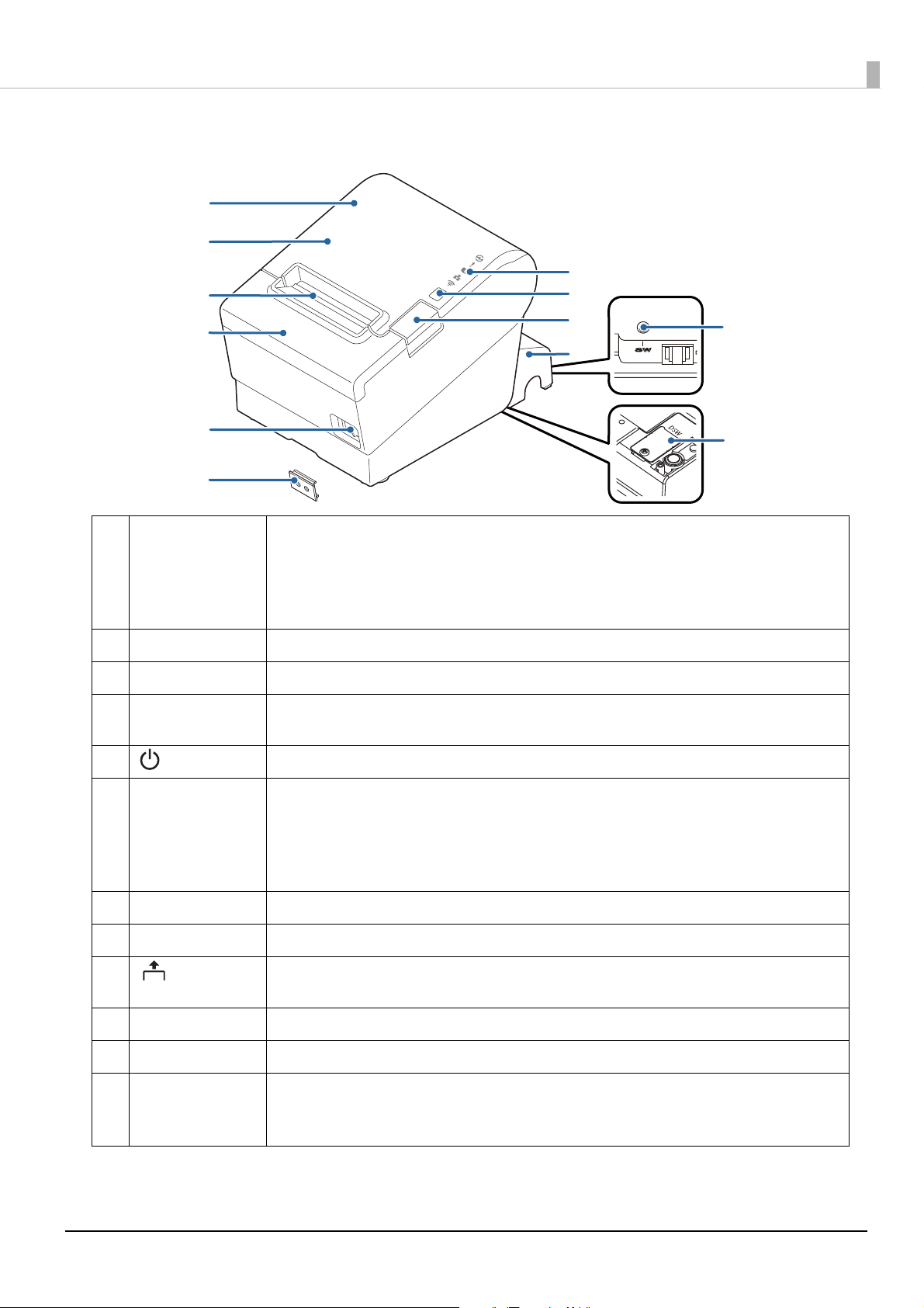
Part Names and Functions
.
1 NFC Tag A mark is printed here to indicate the position of the NFC tag. To establish communication with an
NFC device, bring the device close to this mark. For details on functions that use the NFC tag, refer
to "Useful Functions for Smart Devices" on page 27.
• Ther
e is no data rewriting function.
• Use Epson ePOS SDK to build this function into your application.
2 Roll paper cover Open this cover to install/replace the roll paper.
3 Manual cutter Use this cutter when you cut the roll paper manually.
4 Cutter cover Open this cover to unlock the autocutter blade when the roll paper cover does not open due to a
paper jam.
5 Power switch Turns the printer on or off.
6 Power switch cover Install the power switch cover onto the printer to prevent inadvertent changing of the power
switch, to prevent tampering, and to improve the appearance of the printer.
To operate the power switch, insert an object with a pointed tip such as a ballpoint pen into the
hole on the power switch cover.
For attaching the power switch cover, refer "Attaching the Power Switch Cover" on page 48.
7
Connector cover Use the printer with this cover attached to protect cables.
8 Cover open button Use this button to open the roll paper cover.
9 Feed button Pressing this button once feeds roll paper for one line. Hold down this button to continue feeding
roll paper.
10 Control Panel For details on LED, see "Control Panel" on page 16.
11
Dip switch cover Open the cover to view the dip switches for communication settings.
12 Status sheet button Use this button to print a status sheet on interfaces or initialize the settings on interfaces.
Fixed Interface models have the status sheet button on a different location. See "Fixed Interface
Mo
del" on page 18.
15
Page 16
Chapter 1 Product Overview
When turning off the printer without using the power switch, it is recommended to send a power-off
command to the printer. If you use the power-off sequence, the latest maintenance counter values are
saved. (Maintenance counter values are usually saved every two minutes.)
For information about ESC/POS commands, see the ESC/POS Command Reference.
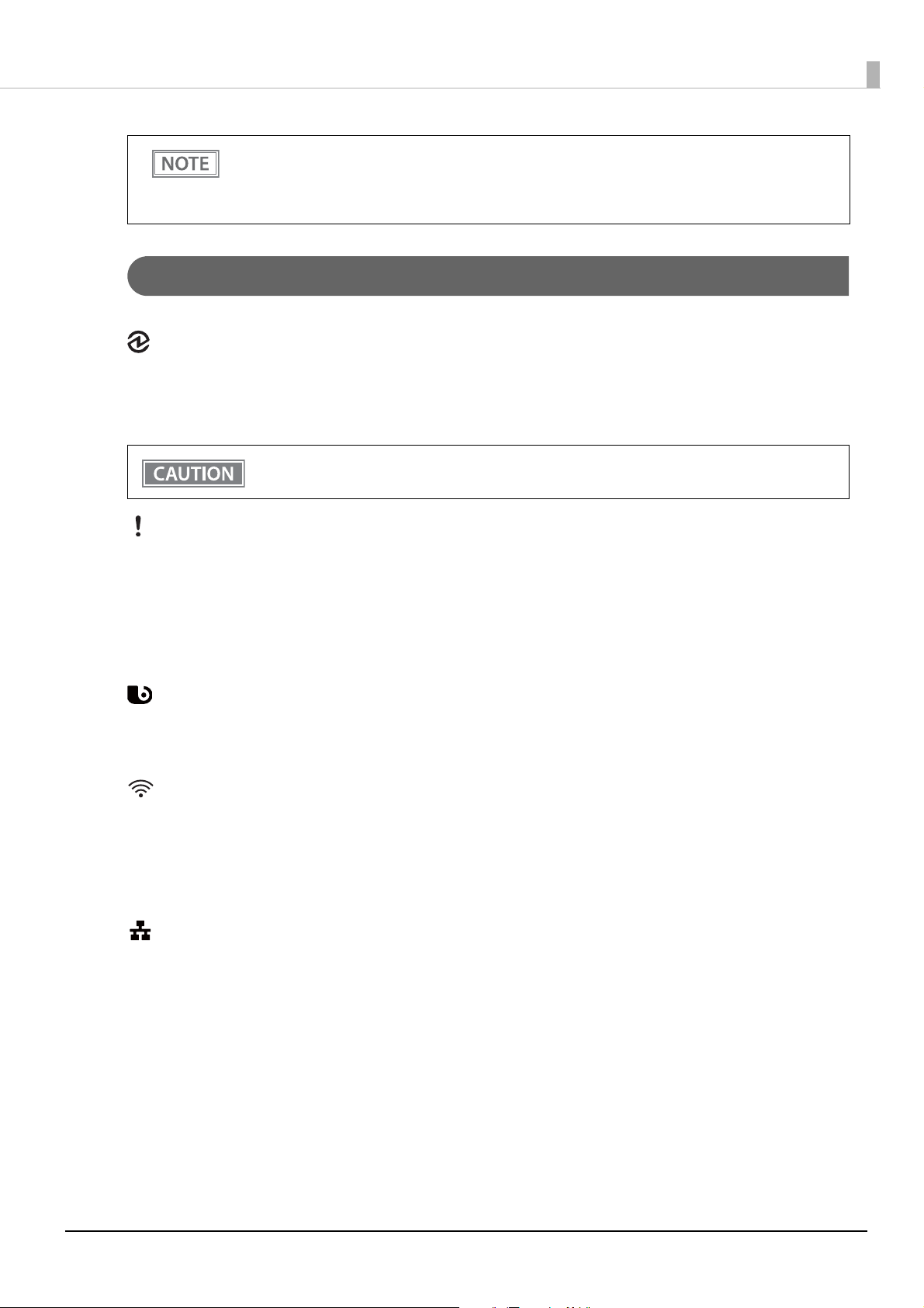
Control Panel
Power LED
• Lights when the power supply is on.
• Off when the power supply is off.
• Flashes during the network to start up, when waiting for power off, or updating firmware.
Do not turn on by using the power switch while waiting for the power to turn off (when the Power
LED is flashing). Otherwise, it may not startup correctly.
Error LED
• Lights or flashes when an error occurs. (For information about the flashing patterns, see "Status and Errors"
on page 20.)
ights after the power is turned on or after a reset (offline). Automatically goes out after a while to indicate
• L
that the printer is ready.
• Off when the printer is in standard mode (online).
Paper LED
• Lights when the roll paper is out.
• Flashes to urge user to operate the Feed button.
Wi-Fi LED
• Lights while the printer is connected to Wi-Fi.
• Off while the printer is not connected to Wi-Fi or while the printer is connected to a wired LAN.
• Flashes while communication is temporarily disabled because an IP address has not been acquired or for
other reason.
Ethernet LED
• Lights while the printer is connected to Ethernet.
• Off while the printer is not connected to Ethernet or while the printer is connected to Wi-Fi.
• Flashes while communication is temporarily disabled because an IP address has not been acquired or for
other reason.
16
Page 17
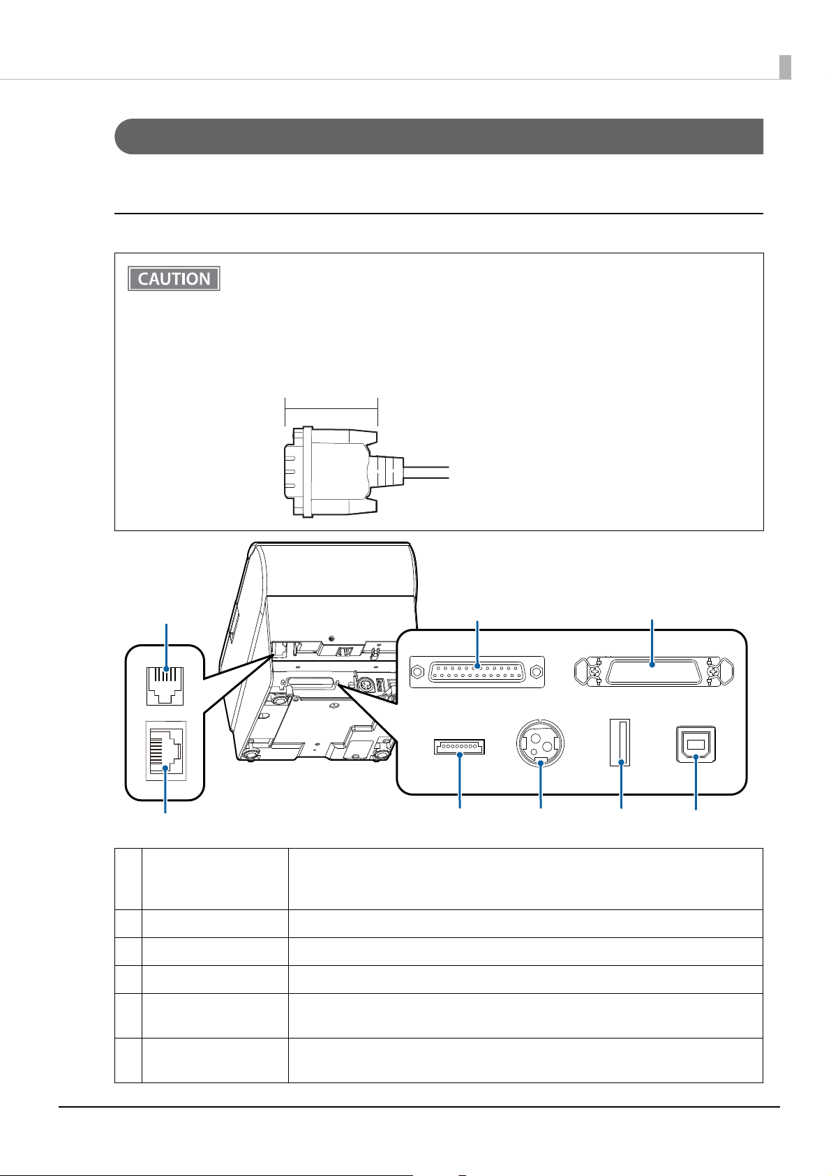
Connectors
All connectors are located on the lower rear of the printer.
Serial/Parallel/Powered USB Models
• The installed interface varies depending on the model.
• Do not insert a Type-B USB connector into the LAN connector or the drawer kick connector. If it
is inserted, the connector, printer, and the system may malfunction.
• If using the drawer kick connector and a serial/parallel connector simultaneously, we recommend
using either of the cables below to prevent the cables from interfering with one another.
* Flat-type drawer kick cable
* Serial/parallel cable with a connector (from the tip to the screw) that is within 34 mm {1.34"}.
Within 34 mm {1.34"}
Chapter 1 Product Overview
1
2
1 Drawer kick connector Connects the cash drawer or the optional external buzzer.
See "Connecting the Cash Drawer" on page 40, and "Connecting the Optional External
Buzz
er" on page 42.
2
Ethernet connector Connects the 10BASE-T/100BASE-TX Ethernet cable.
3 Serial interface Serial model only. Connects the serial cable for connecting to a computer.
4 Parallel interface Parallel model only. Connects the parallel cable for connecting to a computer.
5 USB Plus Power Interface Powered USB model only. Connects the USB Plus Power cable for connecting to a
computer.
3
5
6
4
7
8
6 Power supply connector Connect the AC adapter.
See "Connecting the AC adapter" on page 33.
17
Page 18
Chapter 1 Product Overview
2
1
3 4 5 6
7
7 USB connector Use only for connecting optional Wireless LAN unit and customer display.
CAUTION:
It may be hard to disconnect some types of USB cable. Do not forcibly pull the cable, or
the USB connector and USB cable may be damaged. Contact qualified service personnel
if you encounter the trouble.
8 USB connector (Type B) Connects the USB cable for connecting to a computer.
See "Connecting the Printer to the Host" on page 34.
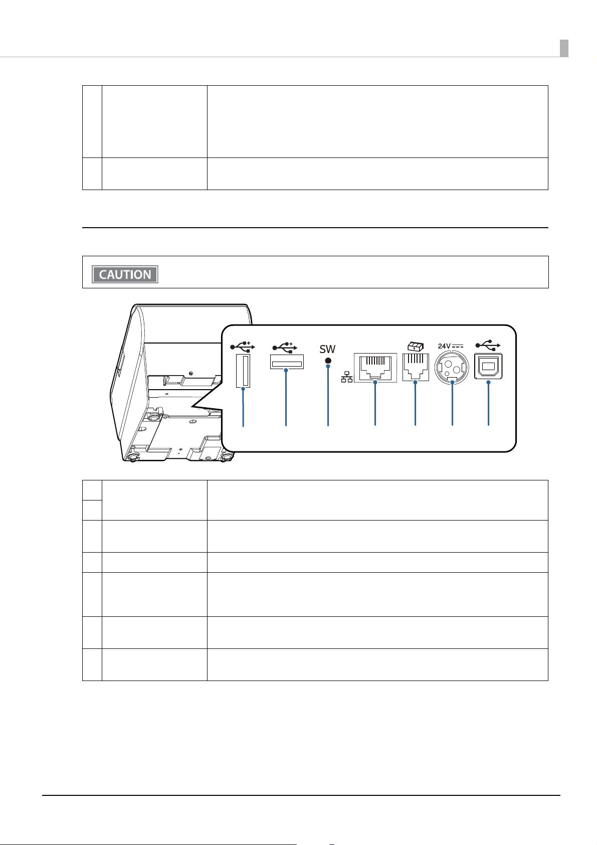
Fixed Interface Model
Do not
insert a Type-B USB connector into the LAN connector or the drawer kick connector. If it is
inserted, the connector, printer, and the system may malfunction.
1
USB connector (Type-A)
2
3 Status sheet button Use this button to print a status sheet on interfaces or initialize the settings on
4 Ethernet connector Connects the 10BASE-T/100BASE-TX Ethernet cable.
5 Drawer kick connector Connects the cash drawer or the optional external buzzer.
6
Power supply connector Connect the AC adapter.
7
USB connector (Type B) Connects the USB cable for connecting to a computer.
Connects a USB cable of a peripheral device such as an optional Wireless LAN cable set,
customer display, or handheld scanner.
interfaces.
See "Connecting the Cash Drawer" on page 40, and "Connecting the Optional External
Buzz
er" on page 42.
See "Connecting the AC adapter" on page 33.
See "Connecting the Printer to the Host" on page 34.
18
Page 19

Chapter 1 Product Overview
Online and Offline
Online
The printer is online and ready for normal printing unless there is a reason to go offline.
Offline
The printer automatically goes offline under the following conditions:
• While the printer power is turning on/off
• While a self-test is running
• While roll paper is fed using the Feed button
• When the printer stops printing due to a paper end (when the paper out detector detected the paper out)
• During an operation standby state
• When an error has occurred (See "Status and Errors" on page 20)
hile the roll paper cover is open
• W
19
Page 20
Status and Errors
The LEDs turn on or flash to indicate status of the printer.
Printing is impossible while an error is occurring.
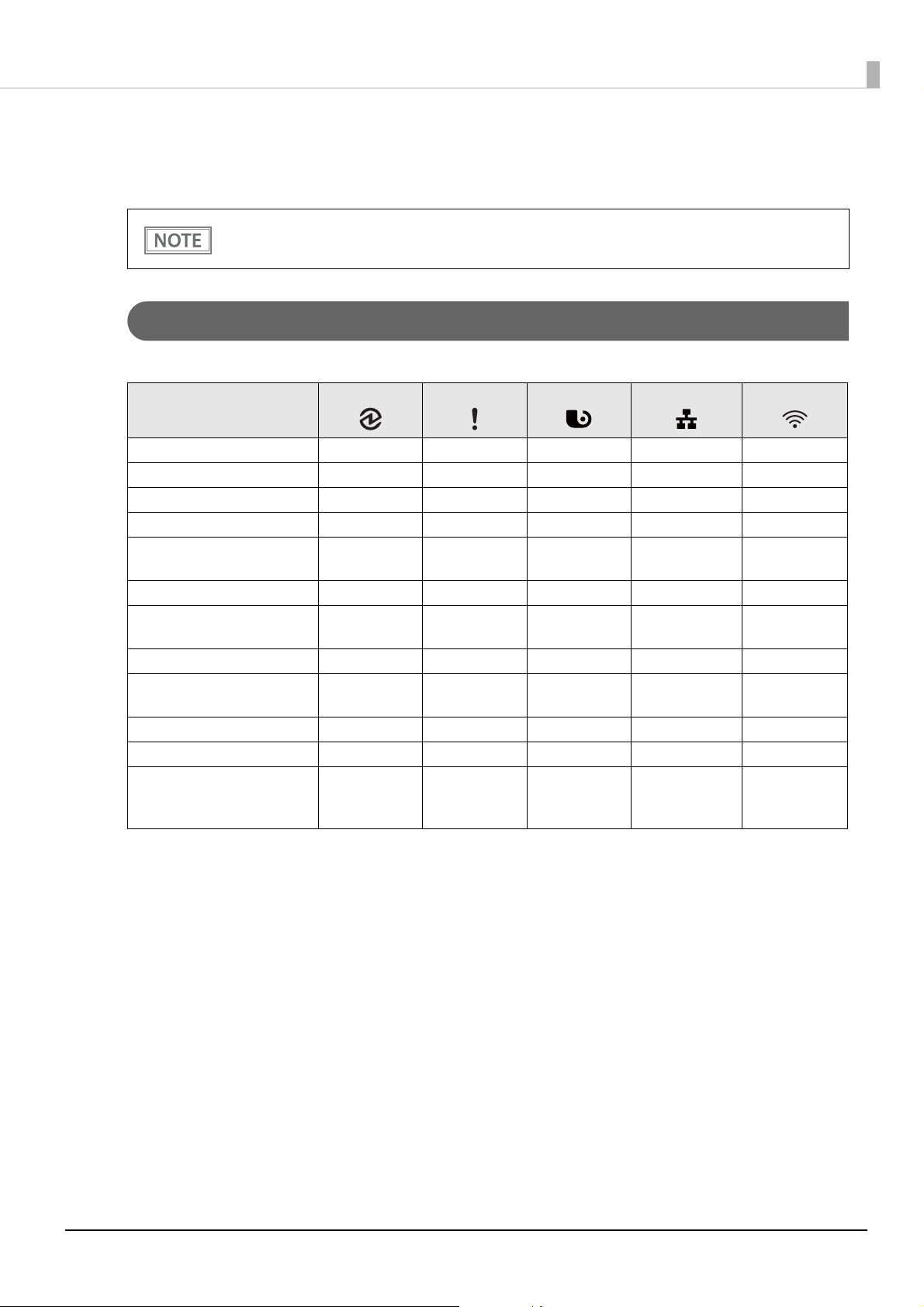
Status Display
Chapter 1 Product Overview
O: OFF N: ON F: Flashing - : Ignore the LED light
POWER LED
Normal state NOO --
Initializing after power-on NN ---
Running a self-test NO ---
Waiting to continue self-test NOF --
Feeding paper using the Feed
button
Waiting to execute a macro NOF --
Roll paper cover open while
not printing
No paper NNN --
Remaining amount of roll
paper is low
Updating firmware FOO --
During power-off process NNO --
Waiting for the roll paper
cover to be closed to print a
status sheet
NO ---
NN ---
NON --
NNF --
ERROR LED PAPER L ED Ethernet LED Wi-Fi LED
∗ -: Changes depending on whether or not paper is detected.
∗ The LED flashing pattern is: lighting for 0.32 s followed by a pause for 0.32 s.
20
Page 21
Chapter 1 Product Overview
0.32 s
LED OFF
LED ON
0.32 s
LED OFF
LED ON
0.32 s
LED OFF
LED ON
0.32 s
LED OFF
LED ON
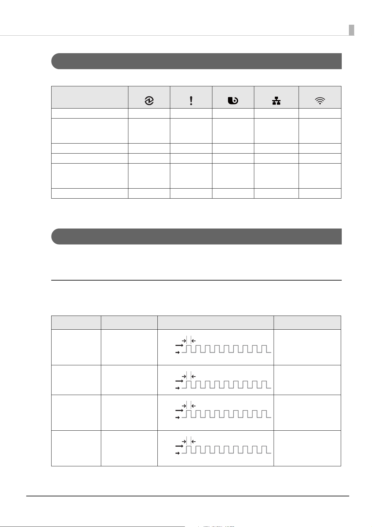
Network Connection Status
O: OFF N: ON F: Flashing - : Ignore the LED light
POWER LED ERROR LED PAPER LED Ethernet LED Wi-Fi LED
Connected to Ethernet NOO N -
In the process of connecting
to Ethernet (An IP address has
not been acquired)
Not connected to Ethernet NOO O -
Connected to Wi-Fi NOO - N
In the process of connecting
to Wi-Fi (An IP address has not
been acquired)
Not connected to Wi-Fi NOO - O
∗ -: Changes depending on whether or not paper is detected.
∗ The LED flashing pattern is: lighting for 0.32 s followed by a pause for 0.32 s.
NOO F -
NOO - F
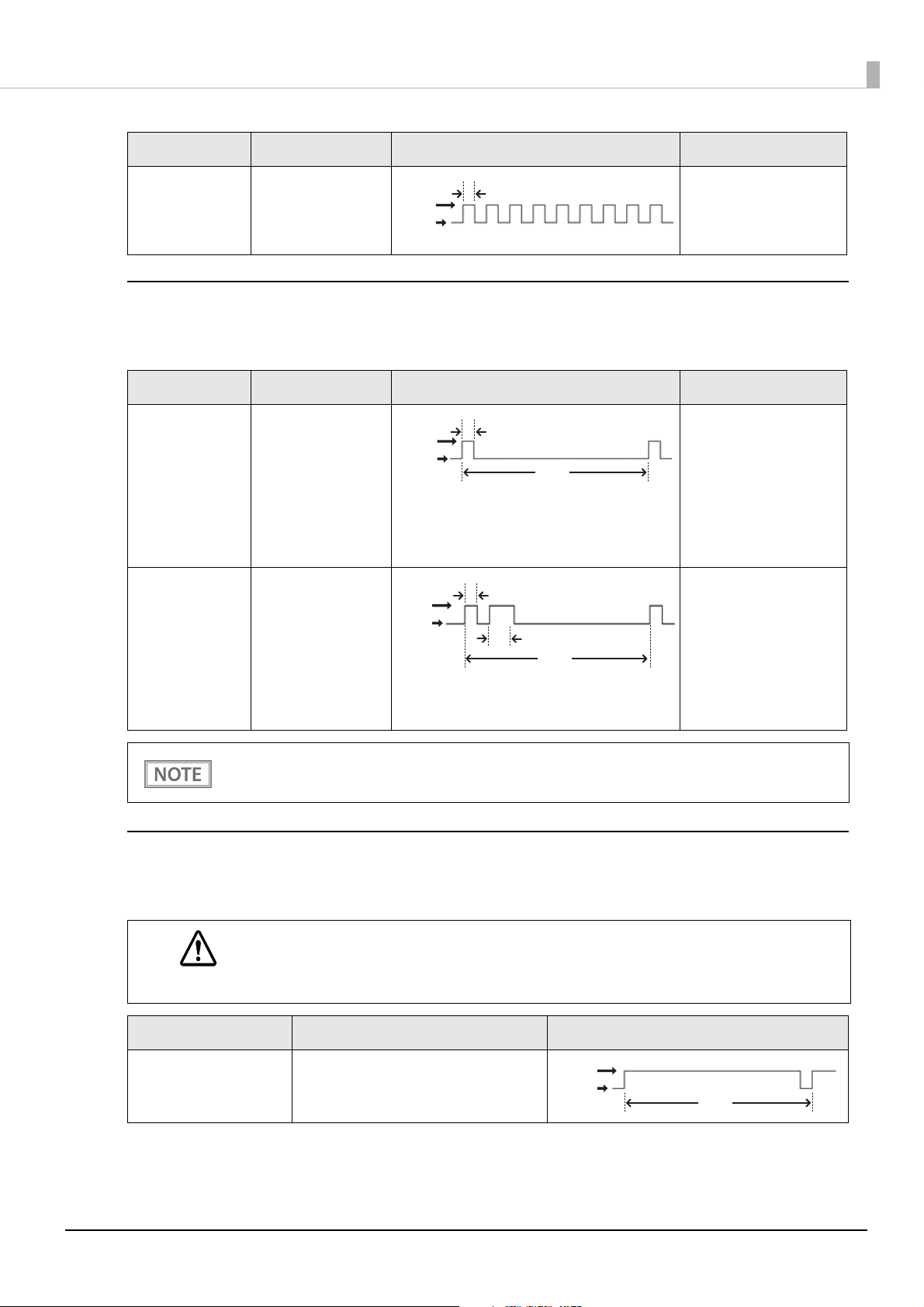
Error Status
There are three possible error types: automatically recoverable errors, recoverable errors, and unrecoverable
errors.
Automatically Recoverable Errors
Printing is impossible while an automatically recoverable error is occurring. The printer recovers from the error
as described below.
Error Explanation Error LED Flashing Pattern Recovery measure
Print head high
temperature error
Cover open error The roll paper cover
Motor driver IC
high temperature
error
A high temperature
beyond the standard
range for driving the
head is detected.
is opened during
printing.
A high temperature
beyond the standard
range for driving the
motor is detected.
The printer recovers from
the error when the head
temperature drops.
The printer recovers from
the error when the cover
is closed.
The printer recovers from
the error after the elapse
of a certain period of
time.
TM-i connection
error
The printer cannot
connect to the
server.
To recover from the error,
correct the printer
settings. (
F
unction" on page 84)
"TM-Intelligent
21
Page 22
Chapter 1 Product Overview
0.32 s
LED OFF
LED ON
0.64 s
0.32 s
5.12 s
LED OFF
LED ON
5.12 s
LED OFF
LED ON
Error Explanation Error LED Flashing Pattern Recovery measure
DC motor heating
error
A high temperature
beyond the standard
range for driving the
motor is detected.
The printer recovers from
the error after the elapse
of a certain period of
time.
Recoverable Errors
Printing is impossible while a recoverable error is occurring. After the error cause is eliminated, the printer
recovers from the error when it is turned off and back on or receives an error recovery command.
Error Explanation Error LED Flashing Pattern Recovery measure
Auto cutter error The autocutter does
not work properly.
DC paper jam
error
The roll paper is
jammed.
LED ON
LED OFF
0.32 s
5.12 s
To recover from the error,
remove jammed paper or
foreign matter in the
printer, close the roll
paper cover, and then
send an error recovery
command, or turn the
printer back on.
To recover from the error,
remove jammed paper or
foreign matter in the
printer, close the roll
paper cover, and then
send an error recovery
command, or turn the
printer back on.
The error recovery command is valid only if a recoverable error (excluding automatically recoverable
errors) occurs.
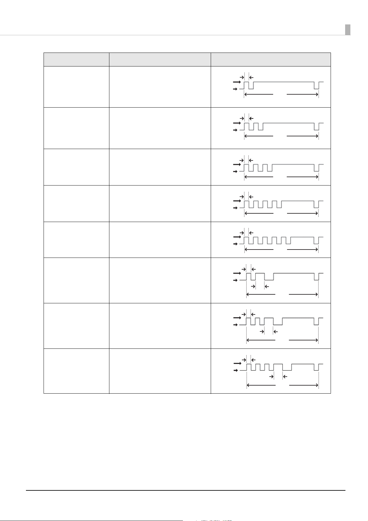
Unrecoverable Errors
Printing is impossible while an unrecoverable errors is occurring. If the error still occurs after turning the
printer off and then back on, the printer may be defective. Contact qualified service personnel.
Turn off the power immediately when unrecoverable errors occur.
CAUTION
Error Explanation Error LED Flashing Pattern
Internal circuit
connection error
Internal circuits are not connected
correctly.
22
Page 23
Chapter 1 Product Overview
0.32 s
5.12 s
LED OFF
LED ON
0.32 s
5.12s
LED OFF
LED ON
0.64 s
0.32 s
5.12 s
LED OFF
LED ON
0.32 s
5.12 s
0.64 s
LED OFF
LED ON
0.32 s
5.12 s
0.64 s
LED OFF
LED ON
Error Explanation Error LED Flashing Pattern
Memory reading/writing
error
After a reading/writing check of the
memory, the printer does not work
correctly.
High voltage error The power supply voltage is extremely
high.
Low voltage error The power supply voltage is extremely
low.
CPU execution error The CPU is executing an incorrect
address.
Communication unit
error
An error has occurred in the
communication unit.
LED ON
LED OFF
LED ON
LED OFF
LED ON
LED OFF
0.32 s
5.12 s
0.32 s
5.12 s
0.32 s
5.12 s
DC reversing error The DC motor is reversing.
DC driving time error DC motor driving time has exceeded the
limit.
DC oscillation error The DC motor is oscillating.
23
Page 24

Chapter 1 Product Overview
NV Memory
The printer's NV memory (Non-Volatile Memory) stores data even after the printer power is turned off. NV
memory contains the following memory areas for the user:
• NV graphics memory
• User NV memory
• Memory switches
• R/E (Receipt Enhancement)
• Maintenance counter
NV memory can be rewritten about 100,000 times. As a guide, NV memory rewriting should be 10
times or less a day when you program applications.
CAUTION
NV Graphics Memory
Graphics, such as shop logos to be printed on receipts, can be stored. Even with a serial interface model whose
communication speed is low, high speed graphics printing is possible.
To register your graphics data, use TM-T88VII Utility or ESC/POS commands.
You can check registered graphics data using TM-T88VII Utility or by printing the data in the NV graphics
information print mode.
User NV Memory
You can store and read text data for multiple purposes, such as for storing a note including customizing or
maintenance information of the printer.
Memory Switches
With the memory switches, which are software switches for the printer, you can configure various settings of the
printer. For information about the memory switch, see "Software Settings" on page 59.
R/E (Receipt Enhancement)
You can set the graphics data, such as a shop logo, registered in the NV graphics memory to be printed on the
top of each receipt or to be printed on the bottom of each receipt just before the paper is cut.
To make the settings, use TM-T88VII Utility or ESC/POS commands.
You can check the settings using TM-T88VII Utility or by printing the settings information in the Receipt
enhancement information print mode.
24
Page 25

Chapter 1 Product Overview
Maintenance Counter
With this function, printer information, such as the number of lines printed, the number of autocuts, and
printer operation time after the printer starts working, is automatically stored in NV memory.
• You can also check the head running length and number of times of autocutting with the self-test
(see "Self-test Mode" on page 71).
• T
he maintenance counter values are automatically saved in the NV memory usually every two
minutes (up to four minutes). However, the values are not saved when the printer is in powersaving mode or when it is turned off without the use of the power switch.
25
Page 26
Chapter 1 Product Overview
SimpleAP Start
SSID : DIR ECT-T M-T88V II- XXXXXXXXXX
Serial number of the printer
Simple Setup for Wireless LAN
The printer has "SimpleAP" mode that allows a device to directly connect to the printer without using an access
point. You can configure wireless LAN settings using the printer setting tool and print on the printer using the
direct connection.
• The printer acts as an access point in the SimpleAP mode and allows up to eight devices to connect
to the printer.
• Connection to a wireless LAN or wired LAN and connection using the SimpleAP mode can be made
at the same time.
• Communication between devices connected to the printer in the SimpleAP mode is impossible.
• If the printer is already connected to a wireless LAN and setting using the SimpleAP mode is
started, the wireless LAN connection is temporarily disconnected.
• If you change the passphrase, connection using SimpleAP from an Android 10 device is disabled. It
may also occur with a device running other OS. If that happens, delete the printer's SimpleAP SSID
profile in the Wi-Fi settings of the Windows, iOS, or Android device, and then connect to the printer
again.
SimpleAP is enabled by default. The printer automatically prints the information shown below when it is turned
on with the following conditions; SimpleAP enabled, not connected to a wireless LAN/wired LAN/USB device,
and wireless LAN settings have not been configured.
The printer activates SimpleAP when it is turned on for the first time, however, if you change the printer
settings using TM-T88VII Utility for Windows or EpsonNet Config, SimpleAP is disabled.
To activate SimpleAP again, start it by selecting the SimpleAP menu that is available after printing a status sheet,
or reset the network settings.
"Setting up from a Windows Computer using SimpleAP" on page 36
"Resetting the Interface Settings" on page 83
26
Page 27

Chapter 1 Product Overview
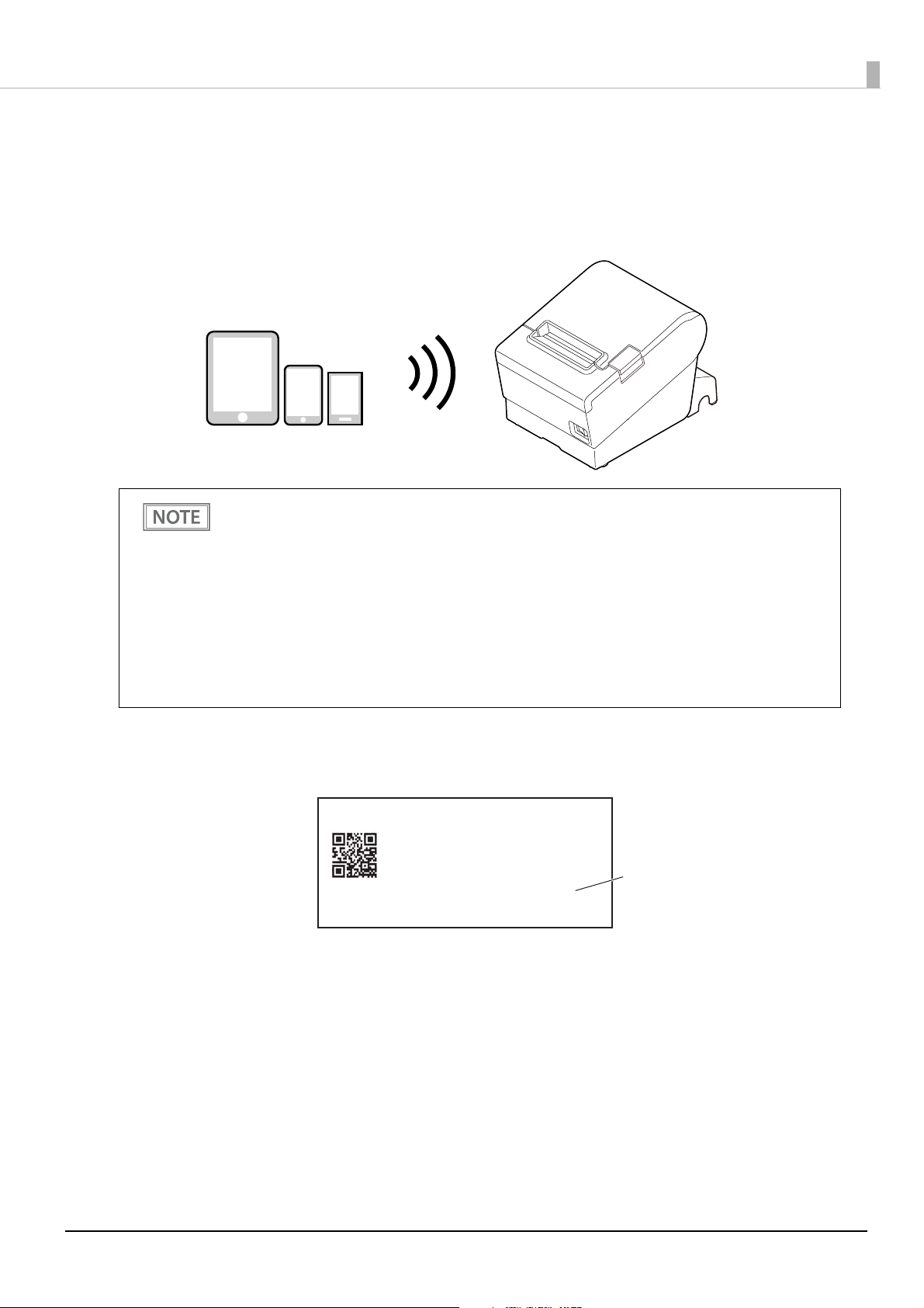
Useful Functions for Smart Devices
You can easily connect this product to the network by using the NFC tag built-in to the printer or the QR code
printed on the status sheet.
NFC Tag
Bring a smart device that supports NFC close to the NFC tag to acquire the printer information (information
for specifying the device).
Specify the target printer using the acquired information to connect to the network.
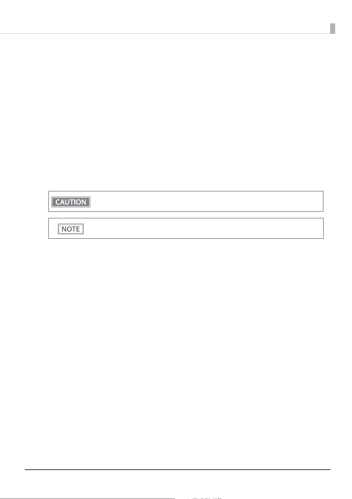
QR Code
Capture the QR code printed on the status sheet with the camera on your smart device to acquire the printer
information (information for specifying the device).
Specify the target printer using the acquired information to connect to the network.
• Programming using Epson ePOS SDK is required to use these functions. These functions are
created by combining NFC touch and QR code capturing operations and the target printer
specifications using Printer Easy Select API.
See the "Epson ePOS SDK for Android/iOS User's Manual" and the Epson ePOS SDK sample
program for more details. The sample program also contains a sample implementation method for
reading an NFC tag and capturing a QR code.
• You can try a demo of these functions by using Epson TM Utility for iOS/Android.
27
Page 28
Chapter 1 Product Overview
Printing Using Multiple Interfaces
In printers with multiple interfaces, you can use all interfaces without any limitations on which interface is to be
used. You can use this function to temporarily connect a smart device to a nearby printer and print.
The printer provides each interface with an independent receive buffer and switches the active interface
depending on the priority, while handling data in each receive buffer.
You can set one interface for the main connection. Data received from the main connection interface is handled
with the highest priority.
By default, the interface that receives the first data transfer is set as the main connection interface; however, you
can select the main connection interface in advance.
In the status where all receive buffers are empty for more than the set time (1 second by default), interface
switching is enabled. The interface that receives the data in this status becomes active.
You cannot use wired and wireless LANs at the same time. When a LAN cable is connected, wireless
LAN is disabled.
You can select the main connection interface and set the time to enable interface switching from the
software settings. For details on software settings, see "Software Settings" on page 59.
28
Page 29
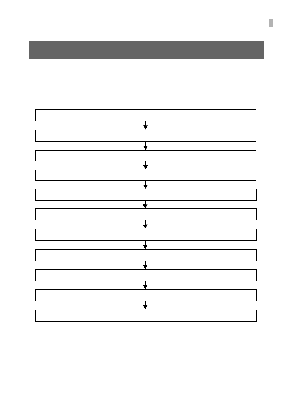
Setup
2. Adjusting the Paper Roll Near-End Sensor (page 31)
5. Connecting the Cash Drawer (page 40)
4. Connecting the Printer to the Host (page 34)
6. Connecting the Optional External Buzzer (page 42)
1. Installing the Printer (page 30)
7. Attaching the Connector Cover (page 44)
8. Arranging the Cables (page 46)
9. Attaching the Power Switch Cover (page 48)
10. Changing the Paper Width (page 49)
3. Connecting the AC adapter (page 33)
11. RTC Settings (page 50)
This chapter describes setup and installation of the product and peripherals.
Flow of Setup
This chapter consists of the following sections along with the setup flow of the product and peripherals.
Chapter 2 Setup
29
Page 30

Chapter 2 Setup
Installing the Printer
You can install this printer horizontally. With an optional hanging bracket (WH-10), you can also attach the
printer to a wall.
Important Notes on Horizontal Installation
• The printer must be installed horizontally on a flat surface (not tilted).
• Do not place the printer in dusty locations.
• Do not catch cables or place foreign matter under the printer.
Important Notes on Wall Hanging
You need to perform the following tasks to install the printer on a wall. For more details, see the installation
manual for the optional wall hanging bracket (WH-10).
• Installing the roll-paper stoppers
• Changing the location of the roll paper near-end sensor
• Attaching the connector cover
• Attaching the wall hanging bracket (WH-10)
For the other notes, see the installation manual for the optional wall hanging bracket (WH-10).
• Be sure to attach the connector cover when you install the printer on a wall using the wall hanging
bracket.
• When installing on a wall using a wall mounting bracket, the status of the wireless signal for the
wireless LAN unit may decline. In this situation, use an extension cable.
30
Page 31

Adjusting the Paper Roll Near-End Sensor
Detection lever
Positioning plate
Adjustment screw
Adjustment screw
Positioning plate
Detection lever
For wall-hanging
For horizontal installation
Knob
Below are two situations where a roll paper NE sensor adjustment is required.
• To adjust the detection position to suit the diameter of the roll paper core used.
• To adjust the detection position of remaining amount of paper.
• Since roll paper cores vary slightly in shape, depending on paper roll design and manufacturing
tolerances, it is impossible to detect the remaining paper exactly.
• To let the NE sensor detect remaining amount of paper accurately, it is recommended to use a roll
paper with a core inner diameter of 12 mm {0.47"} and outer diameter of 18 mm {0.71"}.
• An outer diameter of a paper roll that is detected as near-end varies by usage environment, and/or
paper specifications. Please check operation of the NE sensor by yourself.
Follow the steps below to adjust the roll paper near-end sensor.
Open the roll paper cover, and remove the roll paper.
1
Loosen the adjustment screw fastening the sensor, and then operate the knob to
2
align the top edge of the positioning plate with the upper or lower level.
Chapter 2 Setup
Adjustment position Upper Lower
Outer diameter of a roll to
be detected as near-end
Position of the positioning
plate
Approx. 27 {1.06"} Approx. 23 {0.97"}
31
Page 32

Tighten the adjustment screw.
3
After adjustment, make sure that the detection lever operates smoothly.
4
Chapter 2 Setup
32
Page 33

Connecting the AC adapter
AC adapter
AC cable
Use the Epson PS-180 or an equivalent product as the AC adapter.
• Never insert the AC cable plug into a socket that does not meet the input voltage of the AC
adapter.
WARNING
Connecting the AC adapter
Make sure the printer is turned off.
1
Connect the AC cable to the AC adapter.
2
Doing so may result in damage to the printer.
• Should a fault ever occur, immediately turn off the power to the printer and unplug the AC
cable from the socket.
Chapter 2 Setup
Connect the DC cable of the AC adapter to the power supply connector (stamped
3
24V).
The optional power supply box (OT-BX88VII) is available. You can store the power supply unit in
the box attached to the printer.
33
Page 34

Connecting the Printer to the Host
• Be sure to install the driver before connecting the printer to the host computer.
• The printer uses modular connectors specifically designed for the cash drawer. Do not connect
these connectors to an ordinary telephone line.
USB Interface
When using USB cable to connect with host device, connect the USB cable to the printer, and after starting the
host device, turn the printer on.
• Do not place any weight or stress on the cable when using. Doing so could damage the cable and
connectors.
• Make sure to use a USB 2.0 compliant cable.
• When the printer is connected to an Android device via USB, the connection may be disabled after
changing the printer settings using TM Utility. In that case, restart TM Utility.
Chapter 2 Setup
Ethernet Interface
Use ethernet cable to connect the printer to network via a hub.
Use Epson TM-T88VII Utility for Windows to set network.
For details on Epson TM-T88VII Utility for Windows, refer to TM-T88VII Utility User's Manual.
• When LAN cables are installed outdoors, make sure they are connected through devices that have
surge protection.
Otherwise, the devices can be damaged by lightning.
• Never attempt to connect the drawer kick cable or a standard telephone line cable to the LAN
connector.
As same with Conventional models, you can use WebConfig in the same way.
Start up a web browser and then input the printer's IP address in the address bar.
On the authentication screen, input password as described below.
The default password is the serial number of the printer. You can check the serial number by running a
self-test ("Self-test Mode" on page 71) or on the product ID plate attached to the product.
34
Page 35

Chapter 2 Setup
Wireless LAN Interface (With OT-WL06)
You can connect using a wired cable (LAN/USB), or connect using SimpleAP mode, and setup a wireless LAN
using a network configuration tool. When setting up multiple printers, you can connect using a wired cable
(LAN/USB) and setup a wireless LAN using the Epson Deployment Tool.
Using Epson TM Utility for iOS/Android, you can easily connect the printer to the network from an iOS or
Android devices.
• When using wireless LAN, make sure you disconnect the LAN cable. If a LAN cable is connected,
wireless LAN is disabled.
• When you set up the access point at the same time, set the access point in advance and check that
it operates correctly.
• Examine the radio wave situation in the surrounding area before use.
• Avoid using the same channel that is used in the neighboring shops where Wireless LAN is used.
• Wireless LANs with a frequency band of 2.4 GHz interfere with Bluetooth communication. When
using Bluetooth and Wi-Fi at the same time, we recommend using 5 GHz.
• When using the printer in environments where kitchen microwaves and other devices that may
interfere radio waves are installed, observe the following points.
∗ Keep the printer away from the devices, such as kitchen microwaves, that may cause radio wave
interference.
∗ Use channels that are away from the frequency bands that may cause radio wave interference.
∗ Place shields between the printer and the devices that may cause radio wave interference.
∗ Select either 2.4 GHz or 5 GHz, whichever is free from radio wave interference.
∗ In auto channel setting for the access point, do not select a channel in which the devices may
cause radio wave interference.
For SimpleAP mode, see
"Simple Setup for Wireless LAN" on page 26.
35
Page 36

Setting up from a Windows Computer using SimpleAP
Necessary Items
Prepare the following items.
• Computer for setting: Windows 10/8/7/Vista
Computer equipped with a wireless LAN function
• Utility for setting: Epson TM-T88VII Utility for Windows
Follow the steps below to connect the printer.
Check that the Wireless LAN unit is connected to the printer.
1
Activate SimpleAP on the printer.
2
Check that SSID and QR code is printed. How to activate SimpleAP differs depending on whether network settings have been done or not.
When network settings have Not been done:
The printer activates SimpleAP when it is turned on.
Chapter 2 Setup
After starting the printer, check that the "SimpleAP Start" is printed. If nothing is printed after
70 seconds, you need to enable SimpleAP in interface settings mode.
When network settings have been done:
Activate SimpleAP from the setting menu available after printing the status sheet.
1) Print the status sheet. "Printing a Status Sheet" on page 79
2) Press the Feed button briefly (less than one sec
"SimpleAP mode" is selected in the setting menu.
3) Hold down the Feed button for at least one second.
SimpleAP is activated.
Start TM-T88VII Utility for Windows.
3
The Feed button is disabled when the utility is started.
Connect the printer using SimpleAP.
4
Click [Add port] - [Network] - [Wi-Fi Direct (SimpleAP)], and then add the printer.
When the printer is connected, make the wireless LAN settings.
5
For information about the settings, see TM-T88VII Utility User's Manual.
ond) three times.
When the setting is completed, turn off and back on the printer.
6
36
Page 37

Setting up Using a USB Connection from a Windows Computer
Necessary Items
Prepare the following items.
• Computer for setting: Windows 10/8/7/Vista
• Utility for setting: TM-T88VII Utility for Windows
• USB cable
Follow the steps below to connect the printer.
Connect the printer to a PC via the USB cable.
1
Turn on the host computer.
2
Turn on the printer.
3
Chapter 2 Setup
Start up the TM-T88VII Utility for Windows.
4
When TM-T88VII Utility for Windows starts, the Feed button is disabled.
Select the printer, and then press the [OK] button.
5
If the printer is not displayed, press the "Add Port" button, and then add the printer connected by
USB.
Perform network I/F as well as TCP/IP settings.
6
For details on the settings, see the TM-T88VII Utility User's Manual.
When you have finished making settings, disconnect the USB cable, turn off the
7
printer, and then turn it back on.
37
Page 38

Chapter 2 Setup
Setting up from a Smart Device using Epson TM Utility for iOS/Android
Necessary Items
Prepare the following items.
• Device for setting: iOS or Android device
• Utility for setting: Epson TM Utility for iOS/Android
Run the Epson TM Utility for iOS/Android.
1
Set from “Wi-Fi Setup Wizard” in the menu.
2
Follow the on-screen instructions to complete the settings.
38
Page 39

Chapter 2 Setup
Serial Interface
When connecting to the host computer through a serial interface (RS-232), connect a serial cable to the printer,
start the host computer, and then turn on the printer.
• When using connectors equipped with screws, tighten the screws on both sides to secure the
connectors firmly.
• When using interface cables equipped with a ground line, attach the ground line to the screw hole
marked "FG" on the printer.
Parallel Interface
When connecting to the host computer using a parallel interface, connect the parallel cable to the printer, start
the host computer, and then turn on the printer.
When using interface cables equipped with a ground line, attach the ground line to the screw hole
marked "FG" on the printer.
USB Plus Power Interface
When using a USB Plus Power cable to connect with the host device, connect the flat connector of the USB Plus
Power cable to the printer, and the square connector to the device. After starting the host device, turn the
printer on.
When using USB Plus Power Interface, be careful of the following points.
• Do not connect an AC adapter and USB (Type-B) simultaneously.
• Do not remove or insert the USB Plus Power cable while the printer is still on.
39
Page 40

Chapter 2 Setup
With shielded
Drawer kick connector
Printer side
User side
[Drawer kick side]
Drawer open/
close switch
Drawer kick
solenoid
1
2
3
4
5
6
Connecting the Cash Drawer
• Do not connect both the optional external buzzer and the cash drawer to the printer at the same
time by using a branched connector.
• When the optional external buzzer is enabled with the memory switch (customized values) (see
"Software Settings" on page 59), a cash drawer cannot be used. Be sure to disable it when you use a
cas
h drawer.
• Two driver transistors cannot be energized simultaneously.
• Leave intervals longer than 4 times the drawer driving pulse when sending it continuously.
Cash Drawer Requirements
Specifications of drawers differ depending on makers or models. When you use a drawer other than specified,
make sure its specification meets the following conditions.
Otherwise, devices may be damaged.
• The load, such as a drawer kick solenoid, must be connected between pins 4 and 2 or pins 4 and 5 of the
drawer kick connector.
• When the drawer open/close signal is used, a switch must be provided between drawer kick connector pins 3
and 6.
• The resistance of the load, such as a drawer kick solenoid, must be 24
Ω or more or the input current must be
1A or less.
• Be sure to use the 24V power output on drawer kick connector pin 4 for driving the equipment.
Drawer Connection Diagram
F. G
+24V
Adaptable Connector
RJ12 modular connector
40
Page 41

Pin assignments
Pin number Signal name Direction
1Frame GND -
2 Drawer kick drive signal 1 Output
3 Drawer kick open/close signal Input
4 +24 V -
5 Drawer kick drive signal 2 Output
Chapter 2 Setup
6Signal GND -
6 5 4 3 2 1
Connecting the drawer kick cable
• Use a shield cable for the drawer kick cable.
• When using cash drawer, make sure to use the power supply for printer (connector pins 4).
WARNING
Connect the drawer kick cable to the drawer kick connector by pressing firmly until the connector clicks into
place.
• Do not insert a telephone line into the drawer kick connector.
Doing so may damage the telephone line or printer.
41
Page 42

Chapter 2 Setup
Volume adjustment knob
Connecting the Optional External Buzzer
When the optional external buzzer (model: OT-BZ20) is connected to the drawer kick connector of the printer,
you can set the printer so that it beeps when you send commands, when an error occurs, when executed
autocutting, and when detected paper end. Settings for sound patterns and frequency depending on the
occasions the buzzer beeps are also available.
You need to set with the memory switch (customized values) for buzzer enable/disable setting, sound pattern
setting, and frequency setting. For information about the memory switch (customized values), see "Software
Settings" on page 59.
• Be sure to turn off the printer before you connect/disconnect the optional external buzzer.
• Do not connect both the optional external buzzer and the cash drawer to the printer at the
same time by using a branched connector.
Attachment Position
The optional external buzzer is recommended to be installed in the following positions.
• Do not install the optional external buzzer at the roll paper exit.
• To prevent liquid from entering inside, it is recommended to install the optional external buzzer
so that the volume adjustment knob is positioned sideways or downward.
42
Page 43

Connecting the Optional Wireless LAN Unit
The optional Wireless LAN cable set (OT-WL06) enables you to use the product with a Wi-Fi connection.
For more information, refer to Technical Reference Guide of the Wireless LAN cable set.
• Be sure to turn off the printer when connecting the Wireless LAN unit.
• Depending on the installation conditions of the printer and the routing for cables connected to it,
the status of the radio waves for the Wireless LAN unit may decline. If this does happen, use an
extension cable.
• Do not disconnect the Wireless LAN unit from the printer while the printer is powered.
Chapter 2 Setup
Connecting the Optional Customer Display
You can connect the customer display (DM-D30/DM-D70/DM-D110/DM-D210) to this product, using USB
connection.
For more information, refer to the Technical Reference Guide of the customer display.
• Be sure to turn off the printer when connecting the customer display.
• When using DM-D70 with the serial model and the parallel model, DM-D70 can be used only in the
fixed column and row mode.
• When connecting DM-D70 to the printer, make sure to attach the ferrite core came with DM-D70 to
the USB cable of DM-D70. For more information, refer to DM-D70 Technical Reference Guide.
43
Page 44

Attaching the Connector Cover
Hooks
When using the connector cover, attach the connector cover.
Follow the steps below to attach the connector cover to protect cables.
Turn over the printer.
1
Position the two hooks on both sides of the connector cover so that they hook the
2
printer case.
Chapter 2 Setup
Push the connector cover down to click onto the printer case.
3
44
Page 45

Chapter 2 Setup
• You can use the enclosed screw to fix the connector cover.
• To remove the connector cover, turn the printer over, remove the screw, and push the
connector cover down while pushing both sides of the connector cover inward to detach the
hooks from the printer case.
45
Page 46

Chapter 2 Setup
Hooks
Arranging the Cables
Route the cables when using the connector cover.
Pass the cables through cable exits in the connector cover. The connector cover has cable exits on the back and
both sides.
You can also route the cables out the front by passing them through the notch in the printer bottom.
If you want to pass the USB cable through the cable exit on the back, fit the cable under the hook on the printer
to prevent the cable from coming off and to prevent too much force being applied to the connector section.
46
Page 47

Chapter 2 Setup
• When using cables without lock, use of the bundled cable lock band is recommended.
• You can also attach bottom cover to hide connectors.
Make sure the cable does not get caught when installing.
After the cable arrangement, turn over the printer, and make sure the cables are not pinched.
47
Page 48

Chapter 2 Setup
Attaching the Power Switch Cover
By attaching the power switch cover supplied, you can prevent accidental operations of the power switch. You
can press the power switch by inserting a sharp-pointed object in the holes on the power switch cover. To detach
the cover, use a sharp-pointed object.
If an accident occurs with the power switch cover attached, unplug the power cord immediately.
Continued use may cause fire or shock.
WARNING
48
Page 49

Chapter 2 Setup
Hole
Protrusion
Changing the Paper Width
You can change the paper width from 80 to 58 mm by installing the included 58-mm width roll paper guides.
Follow the steps below to change the paper width.
Once you change the paper width to 58 mm and print on 58-mm width roll paper, you cannot go back
to 80 mm width. Because parts of the print head that do not normally touch the paper may be
damaged by the platen roller, and the autocutter may wear out.
Make sure the printer is turned off.
1
Open the roll paper cover.
2
Install the roll paper guide so that the protrusion on the roll paper holder is aligned
3
with the hole on the printer.
You can use the enclosed screw to fix the roll paper guide.
Set the paper width in software setting mode.
4
For information about the software setting mode, see "Software Settings" on page 59.
49
Page 50

RTC Settings
The time for the RTC (Real Time Clock) may be initialized when starting up for the first time. If the time is
initialized, make settings using the Setup Utilities.
For details on making settings using the Setup Utilities, see the TM-T88VII Utility User's Manual.
Chapter 2 Setup
50
Page 51

Advanced Usage
DSW2 (DIP switch 2)
DSW1 (DIP switch 1)
Fixed Interface model has DSW1 only.
Setting the DIP Switches
On this printer, you can make various settings with DIP switches.
The DIP switches are already set for the current interfaces. Change the setting if necessary.
Functions of the DIP switches differ depending on the interface.
Setting Procedure
Follow the steps below to change the DIP switch settings.
• Before you remove the DIP switch cover, turn off the printer and disconnect all cables.
Otherwise, a short-circuit may cause the printer to malfunction.
CAUTION
• If you open the DIP switch cover, be sure to close the cover and tighten the screw after
adjusting the DIP switch.
Using this product with the cover open may cause fire or electric shock.
Chapter 3 Advanced Usage
• DIP switch settings are enabled only when the power is turned on or the printer is reset via the
interface. If the settings are changed after that, the functions will not change.
• Do not change switches that are fixed to ON or OFF. Otherwise, the printer may not operate
normally.
Make sure the printer is turned off.
1
Unscrew the screw to remove the DIP switch cover from the base of the printer.
2
51
Page 52

Set the DIP switches, using the tip of a tool, such as a small screwdriver.
3
Replace the DIP switch cover, and screw it in place.
4
Chapter 3 Advanced Usage
52
Page 53

Serial Model
DIP Switch Bank 1
Chapter 3 Advanced Usage
SW Function ON OFF
1-1 Data reception error Ignored Prints “?” OFF
1-2 Reserved (Do not change the setting) Fixed to OFF OFF
1-3 Handshaking XON/XOFF DTR/DSR OFF
1-4 Word length 7 bits 8 bits OFF
1-5 Parity check Yes No OFF
1-6 Parity selection Even Odd OFF
1-7
Baud rate selections
1-8 OFF
See the " Transmission Speed (DIP
table below.
Switches 1-7/1-8)"
Transmission Speed (DIP Switches 1-7/1-8)
Transmission speed (bps: bits per second) SW 1-7 SW 1-8
Depends on the software setting mode settings.* ON ON
4800 OFF ON
Default
setting
ON
9600 (default) ON OFF
19200 OFF OFF
bps: bits per second
* The default value of transmission speed set with software settings is 38400 bps. (See "Software Settings" on
pa
ge 59.)
Depending on print conditions, such as print duty, print head temperature, and data transmission
speed, print speed is automatically adjusted, which can cause white lines due to intermittent
print (the motor sometimes stops). To avoid this, set the transmission speed higher or keep the
print speed constant by setting it lower.
53
Page 54

DIP Switch Bank 2
Chapter 3 Advanced Usage
SW Function ON OFF
2-1 Handshaking (BUSY condition) Receive buffer full
2-2 Reserved (Do not change setting) Fixed to OFF OFF
2-3
2-4
2-5
2-6 Reserved (Do not change setting) Fixed to OFF OFF
2-7 I/F pin 6 reset signal Enabled Disabled OFF
2-8 IF pin 25 reset signal Enabled Disabled OFF
Selects print density
Reserved (Do not change setting) Fixed to OFF OFF
• For DIP Switch 2-1 (BUSY condition), see also "Selecting the BUSY Status" on page 58.
• When y
ou use the APD, change the setting of DIP switch 2-1 (BUSY condition) to ON.
See the " Selecting the Print Density (DIP Switches 2-3/2-
4)" table below.
Offline
Receive buffer full
Selecting the Print Density (DIP Switches 2-3/2-4)
Default
setting
OFF
OFF
Function SW 2-3 SW 2-4
Do not set ON ON
Print density (standard) OFF OFF
Print density (medium) ON OFF
Print density (dark) OFF ON
• If the print density is set to “Medium” or “Dark” level, print speed may be reduced.
• The print density can be set with DIP switches (2-3/2-4) or the software settings. (See "Software
Se
ttings" on page 59.)
54
Page 55

Parallel Model/Powered USB Model
DIP Switch Bank 1
Chapter 3 Advanced Usage
SW Function ON OFF
1-1 Auto line feed Always enabled Always disabled OFF
1-2 Reserved (Do not change the setting) Fixed to OFF OFF
Selects paper sensors to output
1-3
1-4 Error signal output*
1-5
1-6
1-7
1-8
paper-end signals (default value of a
command)*
Undefined — OFF
1
Disabled
1
Disabled Enabled OFF
Roll paper end sensor
enabled, roll paper nearend sensor enabled
∗1: For Parallel model only.
DIP Switch Bank 2
SW Function ON OFF
Default
setting
OFF
Default
setting
2-1 Handshaking (BUSY condition) Receive buffer full
2-2 Reserved (Do not change setting) Fixed to OFF OFF
2-3
2-4
2-5
2-6 Reserved (Do not change settings) Fixed to OFF OFF
2-7 Reserved (Do not change settings) Fixed to OFF OFF
2-8
Selects print density
Reserved (Do not change setting) Fixed to OFF OFF
If pin 31 reset signal
Reserved (Do not change settings) Fixed to OFF
*1
See the " Selecting the Print Density (DIP Switches 2-3/2-
4)" table below.
Offline
Receive buffer full
Fixed to ON ON
*2
∗1: For Parallel model only.
∗2: For Powered USB model only.
For DIP Switch 2-1 (BUSY condition), see also "Selecting the BUSY Status" on page 58.
OFF
OFF
OFF
55
Page 56

Selecting the Print Density (DIP Switches 2-3/2-4)
Function SW 2-3 SW 2-4
Do not set ON ON
Print density (standard) OFF OFF
Print density (medium) ON OFF
Print density (dark) OFF ON
• If the print density is set to “Medium” or “Dark” level, print speed may be reduced.
• The print density can be set with DIP switches (2-3/2-4) or the software settings. (See "Software
Settings" on page 59.)
Chapter 3 Advanced Usage
56
Page 57

Fixed Interface Model
DIP Switch Bank
Chapter 3 Advanced Usage
SW Function ON OFF
1 Handshaking (BUSY condition) Receive buffer full
2 Reserved (Do not change setting) Fixed to OFF OFF
3
Selects print density
4
5 Reserved (Do not change setting) Fixed to OFF OFF
6 Reserved (Do not change settings) Fixed to OFF OFF
7 Reserved (Do not change settings) Fixed to OFF OFF
8 Reserved (Do not change settings) Fixed to OFF OFF
For DIP Switch 1 (BUSY condition), see also "Selecting the BUSY Status" on page 58.
See the " Selecting the Print Density (DIP Switches 3/4)"
e below.
tabl
Offline
Receive buffer full
Selecting the Print Density (DIP Switches 3/4)
Default
setting
OFF
OFF
Function SW 3 SW 4
Do not set ON ON
Print density (standard) OFF OFF
Print density (medium) ON OFF
Print density (dark) OFF ON
• If the print density is set to “Medium” or “Dark” level, print speed may be reduced.
• The print density can be set with DIP switches (3/4) or the software settings. (See "Software
Se
ttings" on page 59.)
57
Page 58

Chapter 3 Advanced Usage
Selecting the BUSY Status
With DIP switch 2-1, you can select conditions for invoking a BUSY state as either of the following:
• When the receive buffer is full
• When the receive buffer is full or the printer is offline
In either case above, the printer enters the BUSY state after power is turned on (including resetting
with the interface) and when a self-test is being run.
Printer BUSY Condition and Status of DIP Switch 2-1
Printer status
Offline During the period after power is turned on (including resetting
with the interface) to when the printer is ready to receive data.
During the self-test. BUSY BUSY
When the cover is open. — BUSY
During paper feed with the Feed button. — BUSY
When the printer stops printing due to a paper-end (when
printer has run out of roll paper).
When a macro is executed and waiting for the power is turned
on.
When an error has occurred. — BUSY
When the receive buffer becomes full. BUSY BUSY
DIP SW 2-1
ON OFF
BUSY BUSY
—BUSY
—BUSY
58
Page 59

Chapter 3 Advanced Usage
Software Settings
With the memory switches and customized values, which are software settings for this printer, you can set the
various functions.
For an outline of the functions, see the following section. Use the methods shown in the table below, or ESC/
POS commands for the settings.
Item/Method
Print Density
Print Speed
Automatic Paper Reduction
Auto Paper Feed&Cut at cover close
Paper Width
Top Ma rgin
Character/Font Settings
Interface Selection
Interface Settings
Intelligent Settings
Command Execution (Offline)
Power Supply Output
Other Settings
Software
Setting
Mode
Epson TM-
T88VII Utility
for Windows
*1
*2
Epson TM
Utility for iOS/
Android
*1
*2
Batch rotate print (Upside Down)
Restore & Delete Defined Data
*3
Print Data Parsing setting
Cut Error Release Method
Logo
ePOS-Print
ProxyInfo
Server Direct Print
Status Notification
Customer Display
Network CS Authentication
Network Dev Info
Ethernet Config
Wi-Fi Config
SSL/TLS Config
*4
59
Page 60

Chapter 3 Advanced Usage
Software
Item/Method
Setting
T88VII Utility
Mode
Certificate Config
TCP/IP Config
SNMP Config
Time Config
LPR Config
Port9100 Config
IP/Port Filter Config
∗1: Except for "Thai Character Composition" and "Embedded Font Replacement".
∗2: Only "Buzzer Control" can be set.
∗3: The setting item may not be available depending on the area.
∗4: Can be set on WebConfig that can be accessed from the TM-Utility.
• The software setting mode is the mode set using the printer's panel. For details on panel
operations, see "Software Setting Mode" on page 73.
• For details about the items that can be set with ESC/POS commands and the setting method,
see the ESC/POS command reference.
• If the same setting is set using the DIP switch, the DIP switch setting is applied.
Epson TM-
Epson TM
Utility for iOS/
for Windows
Android
*4
60
Page 61
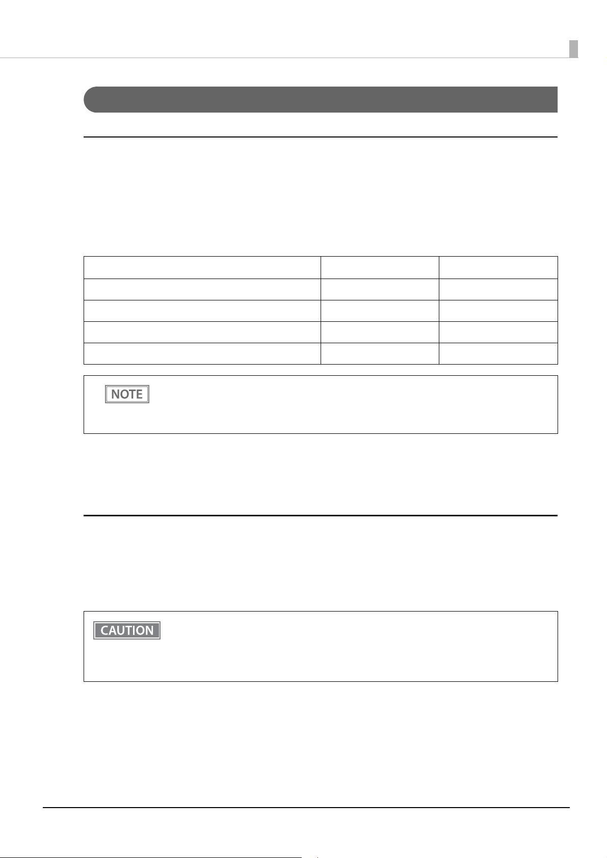
Chapter 3 Advanced Usage
Functions
Print Density
Monochrome
Selectable from 70 to 130% (5% increment)
Default setting: 100%
Depending on the paper type, it is recommended to set the print density as shown in the table below for the best
print quality.
Original Paper type Density Print speed
AP50KS-ND 100% 17 (500 mm/sec)
KT55FA, AP45KS-ND 100% 16 (450 mm/sec)
KT48FA, KT55PF 100% 15 (400 mm/sec)
KT48PF, P5047(55), P5047(46) 105% 15 (400 mm/sec)
• When the print density level is increased, print speed may be reduced. When printing at a
density of 115% or more and below a room temperature of 15°C, the speed drops to less than
200 mm/sec.
• When setting the print speed to level 17, use customized values to set the print density.
Multi-Tone
Selectable from 70 to 130% (5% increment)
Default setting: 100%
Print Speed
• High Speed (500 mm/s)
• Standard Speed (450 mm/s) (default setting)
• Middle Speed (350 mm/s)
*Default setting: Varies by country/region where the printer is purchased
• The print speed is restricted according to the Number of head energizing parts setting.
The maximum 500 mm/s is possible with the One-part energizing (default) option.
The Number of head energizing parts setting can be changed using ESC/POS commands. ("ESC/
POS" on
• The maximum
page 85)
printing speed when using 58 mm is 450 mm/s.
61
Page 62

• When setting the print speed to [High Speed], set the print density using Customized Value
Setting.
• Depending on print conditions, such as print duty, print head temperature, and data
transmission speed, print speed is automatically adjusted, which may cause white lines due to
intermittent print (the motor sometimes stops). To avoid this, keep the print speed constant by
setting it lower.
• By using a setting tool such as TM-T88VII Utility, the print speed can be selected from 17 levels
(from the slowest level 1 to the fastest level 17). (Default setting: level 16)
Automatic Paper Reduction
Upper Margin
• Enable
• Disable (default setting)
Lower Margin
• Enable
• Disable (default setting)
Chapter 3 Advanced Usage
Blank Line Spacing
• 25%
• 50%
• 75%
• Not Reduce (default setting)
Blank Space
• 25%
• 50%
• 75%
• Not Reduce (default setting)
Barcode Height
• 25%
• 50%
• 75%
• Not Reduce (default setting)
Character Height
• Inner Spacing
• Inner Spacing & Height
• Not Reduce (default setting)
• No reduction is applied to blank dot lines that exist in a graphic data.
• Reduced barcodes are not guaranteed to be correctly scanned. Make sure to check whether
they are properly read by a barcode reader that is actually used.
62
Page 63

Auto Paper Feed&Cut at cover close
• Enable
• Disable (default setting)
Paper Width
• 80 mm (default setting)
• 58 mm
Top Margin
Selectable from levels 15 ~ 2 mm (0.5 mm interval)
Default setting: level 15 mm
• Remove all ejected paper before printing with backfeed.
• Disable the automatic top logo setting when enabling backfeed.
• You cannot use backfeed in the following cases even if you have enabled backfeed.
∗ Immediately after auto cutting while the cover is closed.
∗ While the self-test is in progress.
• If setting a top margin of 5 mm {0.2"} or less, confirm that no errors occur in your environment of
usage. Usage in a hot and humid environment or usage of paper that curls easily may increase
the risk of paper jams.
• When implementing a backfeed, rubbing smears may occur due to slack in the paper. We
recommend using thermal paper with high rub resistance.
Chapter 3 Advanced Usage
Character/Font Settings
Default Character Code Page
Selectable from 43 pages including user defined page
Initial setting: PC437: USA, Standard Europe
Default International Character Set
Selectable from 18 sets
Initial setting: USA
Thai Character Composition
• 3 pass
• 1 pass (default setting)
63
Page 64

Embedded Font Replacement
Font A Replacement
• Does not replace (default setting)
• Font B
• Special Font A
• Special Font B
Font B Replacement
• Does not replace (default setting)
• Font A
• Special Font A
• Special Font B
Multi-Language Font
• Thai, Vietnam (default setting)
• Simplified Chinese
Chapter 3 Advanced Usage
Font Priority
• ANK
• Japanese (default setting)
• Simplified Chinese
• Traditional Chinese
• Korean
Interface Selection
• UIB (Serial, Parallel, and Power Plus USB models only)
• Built-in USB
• Ethernet/Wi-Fi
• Auto
• Multiple (default setting)
Interface Settings
Serial Interface Baud Rate
• 2400 bps
• 4800 bps
• 9600 bps
• 19200 bps
• 38400 bps (default setting)
• 57600 bps
• 115200 bps
64
Page 65

USB Interface Settings
Class
• Vendor Class (default setting)
• Printer Class
IEEE1284 Device ID
• Do not output IEEE1284 Device ID
• Output IEEE1284 Device ID (default setting)
USB power-saving function
• Enable
• Disable (default setting)
• The Class setting is applied only to the USB Type B connector.
• The USB power-saving function is valid only when the USB interface communication condition
is set to the vendor-defined class and the system configuration is set so that the USB driver can
support the USB power-saving function.
Chapter 3 Advanced Usage
Interface switch waiting time
Select the number of seconds from 1 to 10 in increments of 1 second, or 60 seconds.
Default setting: 10 seconds
Main connection interface
• UIB
• Built-in USB
• Ethernet/Wi-Fi
• Auto (default setting)
• No main connection I/F
• When using this printer with multiple interfaces, make sure the interface that is always
connected to be set as the main connection.
• You cannot use wired LAN and wireless LAN at the same time.
• The displayed items vary depending on the interface configuration.
• For information about the function, see "Printing Using Multiple Interfaces" on page 28.
Auto Line Feed
• Always disabled (default setting)
• Always enabled
This is only enabled when using a serial interface. When using another interface, make settings by
using
the DIP switches.
65
Page 66

Output Paper-end Signals
• Enable (default setting)
• Disable
When using a parallel interface, make settings by using the DIP switches.
Error Signal Output
• Enable (default setting)
• Disable
When using a parallel interface, make settings by using the DIP switches.
Intelligent Settings
Print Data Parsing
Chapter 3 Advanced Usage
• Enable
• Disable (default setting)
The setting item may not be available depending on the region.
Command Execution (Offline)
• Enable
• Disable (default setting)
Power Supply Output
Selectable from levels 1 to 3 low power load
Default setting: level 3
66
Page 67

Other Settings
Printer Model
• TM-T88VII (default setting)
• TM-T88V
• TM-T88VI
Column Emulation
• 42/30 Column Mode (default setting)
• 48/36 Column mode
This function is supported only on the ANK model.
NV Capacity
User NV Memory
• 1KB (default setting)
Chapter 3 Advanced Usage
• 64KB
• 128KB
• 192KB
NV Graphics Memory
• 256KB(default setting)
• 320KB
• 384KB
Buzzer Control
• For information about how to connect the optional external buzzer, see "Connecting the
Optional External Buzzer" on page 42.
• When
it when you use a cash drawer.
Option Buzzer
• Enable
• Disable (default setting)
the optional external buzzer is enabled, a cash drawer cannot be used. Be sure to disable
Buzzer Frequency (Error)
• Continuous (default setting)
• 1 time
• No sound
67
Page 68

Sound Pattern (Autocut)
Selectable from Patterns A to E
Default setting: Pattern A
Buzzer Frequency (Autocut)
• 1 time (default setting)
• No sound
Sound Pattern (Pulse 1)
Selectable from Patterns A to E
Default setting: Pattern A
Buzzer Frequency (Pulse 1)
• 1 time (default setting)
• No sound
Chapter 3 Advanced Usage
Sound Pattern (Pulse 2)
Selectable from Patterns A to E
Default setting: Pattern B
Buzzer Frequency (Pulse 2)
• 1 time (default setting)
• No sound
68
Page 69

Chapter 3 Advanced Usage
Setting/Checking Modes
As well as print mode, the following modes are also provided for making various printer settings and checking
items.
• Self-test mode
• NV graphics information print mode
• Receipt Enhancement information print mode
• Software settings mode
• Restore default values mode
• Interface setup mode
• TM-Intelligent settings information print mode
• Hexadecimal dumping mode
The self-test mode or hexadecimal dumping mode is selected depending on the operation performed when the
power is turned on.
NV graphic information print mode, Receipt Enhancement information print mode, Software settings mode,
and Restore default settings mode are selected depending on the Feed button operation performed during a
self-test.
Close the roll paper cover, and turn on the printer while pressing the Feed button.
Self-test
Briey press the Feed button. Hold down the Feed button.
Continuing the self-test
Press the Feed
button once briey
and then hold it
down.
NV Graphics
Information
Open the roll paper cover, and turn on the printer while pressing the Feed
Press the Feed
button twice briey
and then hold it
Enhancement
Information
button, and then close the roll paper cover.
Hexadecimal dumping
Mode selection guidance
down.
Receipt
Press the Feed button
three times briey
and then hold it
down.
Software Settings
Press the Feed
button four times
briey and then hold
it down.
Restore Default
Values
Press the Feed button
ve times briey and
then hold it down.
Interface Setup
Press the Feed
button six times
briey and then hold
it down.
TM-Intelligent
settings information
print
Press the Feed
button seven times
briey and then hold
it down.
Peripheral Device
Information print
69
Page 70

Chapter 3 Advanced Usage
Mode Selection
Modes
0: Exit and Reboot Printer
1: NV Graphics Information
2: Receipt Enhancement Information
3: Customize Value Settings
4: Restore Default Values
5: Interface Setup
6: TM-Intelligent Information
7: Peripheral Device Information
8 or more: None
Select Modes by executing following
procedure.
step 1. Press the Feed button less
than 1 second as many times
as the selected mode number.
step 2. Press Feed button for 1
second or more.
In 1 and 2, the following guidances are printed, the Paper LED flashes, and instructs the user's operations.
1. Continuing self-test guidance
2. Mode selection guidance
70
Page 71

Chapter 3 Advanced Usage
Self-test Mode
You can check the following items using the self-test.
• Product name
• Firmware version
• Product serial number
• Interface type
• Resident fonts
• Maintenance counter information (head running length, number of times of autocutting)
• Setting condition of the DIP switch
Follow the steps below. You can also run the self-test using the ESC/POS commands.
Close the roll paper cover.
1
While pressing the Feed button, turn on the printer. (Hold down the Feed button
2
until printing starts.)
After printing the current print status, a Continuing self-test guidance is printed, and the Power LED
flashes.
Briefly press the Feed button (less than one second) to continue the self-test.
3
The printer prints a rolling pattern on the roll paper, using the built-in character set.
After “*** completed ***” is printed, the printer initializes and switches to standard mode.
NV Graphics Information Print Mode
Prints the following NV graphic information registered to the printer.
• Capacity of the NV graphics
• Used capacity of the NV graphics
• Unused capacity of the NV graphics
• Number of NV graphics that are registered
• Key code, number of dots in X direction, number of dots in Y direction to be defined.
• NV graphics data
For details on NV graphics, see "NV Graphics Memory" on page 24.
71
Page 72

Chapter 3 Advanced Usage
Follow the steps below.
After running a self-test, hold down the Feed button for at least one second, and then
1
select the Mode selection.
The Mode selection guidance is printed, and the Paper LED flashes.
After briefly (less than one second) pressing the Feed button once, hold it down for at
2
least one second, to print the NV graphics information.
After information printing, the Mode selection guidance is printed again.
To finish, turn off the power, or select “Exit and Reboot Printer”.
3
Receipt Enhancement Information Print Mode
You can check the following items using the R/E information mode:
• Automatic top logo setting
• Automatic bottom logo setting
• Extended settings for automatic top/bottom logo
Follow the steps below.
After running a self-test, hold down the Feed button for at least one second, and then
1
select the Mode selection.
The Mode selection guidance is printed, and the Power LED flashes.
After briefly (less than one second) pressing the Feed button twice, hold it down for
2
at least one second, to print the R/E information.
After information printing, the Mode selection guidance is printed again.
To finish, turn off the power, or select "Exit and Reboot Printer".
3
72
Page 73

Software Setting Mode
Set the printer's memory switches and customized values.
• Print density
• Auto reduction of amount of paper to use
• Enabling/disabling paper autocutting at cover close
• Paper width setting
• Auto replacement of font
• Print speed
• Command execution (offline)
• Specification for the top margin by backfeed
• Optional external buzzer control
• Interface setting
• Communication conditions using a serial interface
• Communication conditions using a USB interface
Chapter 3 Advanced Usage
• Interface switch wait time
• Main interface selection
• Power supply capacity
• Automatic line feed
• Select paper sensor(s) to output paper-end signals
• ERROR signal when an error occurs
• Thai Character Composition
• Character code table defaults
• International character defaults
For details on the memory switches and customized values, see "Software Settings" on page 59.
Follow the steps below.
After running a self-test, hold down the Feed button for at least one second to enter
1
the Mode selection.
The Mode selection guidance is printed, and the Paper LED flashes.
Briefly press the Feed button three times (less than one second), hold it down for at
2
least one second to enter the Software settings mode (Customized value setting).
The Software setting mode guidance is printed, and the Paper LED flashes.
73
Page 74

Customize Value Settings
Modes
0: Exit
1: Print Current Settings
2: Print Density
3: Print Speed
4: Automatic Paper Reduction
5:
Auto Paper Feed&Cut at cover close
6: Paper Width
7: Top Margin
8: Character/Font Settings
9: Interface Selection
10: Interface Settings
11: Intelligent Settings
12: Command Execution (Oine)
13: Power Supply Output
14: Other Settings
Select Modes by executing following
procedure.
step 1. Press the Feed button less
than 1 second as many times
as the selected mode number.
step 2. Press Feed button for 1
second or more.
Chapter 3 Advanced Usage
After briefly pressing the Feed button (less than one second) for the number of times
3
shown in the print result, hold down the button for more than one second to select
the setting items.
The setting selected as the setting item, the current settings and default settings are printed.
Depending on the setting item, you may need to continue selecting the setting item before the
settings are printed.
For details on setting items, see "Software Settings" on page 59.
When set to a value other than those in the software setting mode, the current settings are not
printed.
Select a setting by briefly pressing the Feed button (less than one second) for the
4
number of times applicable to the setting, and then hold down the button for more
than one second to confirm your selection.
After saving the settings, the Software setting mode guidance is printed, and the Paper LED flashes.
To close Software setting mode, turn off the printer, or select “Exit” to return to Mode
5
selection guidance, and then select “Exit and Reboot Printer”.
• To select 0 as the item number, hold down the Feed button until printing starts.
• If the button is pressed a number of times that is not displayed by the Setup guidance, the
operation is invalid and the same guidance is printed.
74
Page 75

Chapter 3 Advanced Usage
Restore Default Values Mode
In Restore default values mode, following values saved on NV Memory will be set back to default settings.
When any error occurs, you can use to specify the reason.
Setting Contents Setting Items
Customized value
Memory switch
R/E (Receipt Enhancement) settings
Communication condition of USB interface
Communication condition of network interface
TM-Intelligent function settings
NV graphics -
NV bit image -
User-defined page -
User NV Memory -
Follow the steps below.
Restore Default Values
and Delete Defined Data
After running a self-test, hold down the Feed button for at least one second to enter
1
the Mode selection.
The Mode selection guidance is printed, and the Paper LED flashes.
Briefly press the Feed button four times (less than one second), hold it down for at
2
least one second to enter the Restore Default Values.
The guidance is printed.
When only restoring the default settings:
3
Briefly press the Feed button once (less than one second), hold it down for at least
one second. (Hold down the Feed button until the message of restore completion is
printed.)
When restoring default settings and deleting user defined data:
Briefly press the Feed button twice (less than one second), and then hold it down for
at least one second. (Hold down the Feed button until the restoration complete
message is printed.)
To finish, turn off the power.
4
75
Page 76

Chapter 3 Advanced Usage
Interface Setup Mode
Use this mode to setup the interface and other settings.
Follow the steps below.
After running a self-test, hold down the Feed button for at least one second to enter
1
the Mode selection.
The Mode selection guidance is printed, and the Paper LED flashes.
Briefly press the Feed button five times (less than one second), hold it down for at
2
least one second to enter the Interface Setup mode.
The guidance is printed.
After briefly pressing the Feed button (less than one second) for the number of times
3
shown in the print result, hold down the button for more than one second to select
the setting items.
Initialize
Select [Wi-Fi & Ethernet Setup] and select [Initialize] to restore the communication settings to the factory
default. The printer is reset and restarted.
SimpleAP mode (With OT-WL06)
In Wi-Fi model, select [Wi-Fi & Ethernet Setup] and select [SimpleAP] to start in SimpleAP mode (the same as
the factory default setting). The printer is reset and restarted, and several lines starting with "SimpleAP Start"
and a QR code are printed.
Select this to use Quick connection for Wi-Fi model.
For information on the Quick connection function, see "Simple Setup for Wireless LAN" on page 26.
76
Page 77

Chapter 3 Advanced Usage
TM-Intelligent Settings Information Print Mode
This function allows you to print TM-Intelligent setting information currently registered in the printer.
Follow the steps below.
After running a self-test, hold down the Feed button for at least one second to enter
1
the Mode selection.
The Mode selection guidance is printed, and the Paper LED flashes.
Briefly press the Feed button six times (less than one second), hold it down for at
2
least one second to print the TM-Intelligent setting information.
After information printing, the Mode selection guidance is printed again.
To finish, turn off the power, or select “Exit and Reboot Printer”.
3
Peripheral Device Information Print Mode
This function allows you to print information for the device currently connected to the printer.
Customer display information
Wi-Fi adapter information
Follow the steps below.
After running a self-test, hold down the Feed button for at least one second to enter
1
the Mode selection.
The Mode selection guidance is printed, and the Paper LED flashes.
Briefly press the Feed button seven times (less than one second), hold it down for at
2
least one second to print the Peripheral Device Information.
After information printing, the Mode selection guidance is printed again.
To finish, turn off the power, or select “Exit and Reboot Printer”.
3
77
Page 78

Chapter 3 Advanced Usage
Hexadecimal Dumping Mode
In hexadecimal dumping mode, data from the host device is printed in hexadecimal numbers and characters.
By comparing the print outs and the program, you can check whether or not data is being sent to the printer
correctly.
• When there are no characters that correspond to the print data, “ . ” is printed.
• If you press the Feed button when there is less than one line of print data, one line is printed.
• During hexadecimal dumping mode, applications that check the printer status may not operate
correctly. The printer only returns the status for the “Real-time transmission status” command.
Follow the steps below. Entering the hexadecimal dumping mode is also possible using the ESC/POS commands.
Open the roll paper cover.
1
While pressing the Feed button, turn on the printer. (Hold down the Feed button
2
until the Error LED turns on.)
Close the roll paper cover.
3
From this point, all data received by the printer is printed in the corresponding hexadecimal
numbers and ASCII characters.
Example of printing in hexadecimal dumping mode:
To close hexadecimal dumping mode, turn off the printer after printing is complete,
4
or press the Feed button for three times.
78
Page 79

Printing a Status Sheet
Follow the steps below to check the interface settings.
When the power LED is flashing, wait until it remains lit to start printing.
Using the Status Sheet Button
If there is a connector cover, remove the cover.
1
See "Attaching the Connector Cover" on page 44 for details on removing the connector cover.
Check that the printer is turned on.
2
Make sure the roll paper cover is closed.
Hold down the status sheet button for at least three seconds.
3
The status sheet is printed.
To let the printer back to normal mode, hold down the Feed button for at least one second.
Chapter 3 Advanced Usage
Using the Feed button
Check that the printer is on.
1
Open the roll paper cover.
2
Hold down the Feed button for at least one second.
3
Close the roll paper cover.
4
The status sheet is printed.
To let the printer back to normal mode, hold down the Feed button for at least one second.
• After the status sheet is printed, only the print settings of the mainly connected interface are
retained. For the mainly connected interface, see "Printing Using Multiple Interfaces" on page
28.
• Ether
• "(none)" is printed for the "Connected Peripheral" if no peripherals are connected to the USB
net and Wi-Fi status sheets are not printed while the printing communication protocol is
being established. They will be printed after the connection is cut off (including being cut due to
a time out).
downstream port connector.
79
Page 80

Chapter 3 Advanced Usage
Setting menus are printed following the status sheet, and you can perform any one of the following
by using the Feed button.
• Print TM-i status sheet
The intelligent function connects to the server and the connection status is printed.
• Print network connection check report
Network connection is checked and the check result report is printed. For more details, see
"Network Connection Check" on page 82.
• A
ctivate SimpleAP
Activate SimpleAP to establish direct wireless connection with the printer. For more details, see
"Simple Setup for Wireless LAN" on page 26.
80
Page 81

Status Sheet Print Sample
<Wireless>
Wireless On
Comm Mode Infrastructure
Operation Mode IEEE802.11b/g/n
Comm Speed Auto(5.5Mbps)
SSID $$$$$$$$$1$$$$$$$$$2.
$$$$$$$$3$$
Channel None
Security Level WPA2/WPA3-Enterprise
AP Auth Method Auto(Open System)
Link Status Disconnected
Link Down(recent) xxxx
Link Down(total) xxxx
AP(MAC Address) XX:XX:XX:XX:XX:XX
Signal Strength Good
Config method WPS-PIN
WPS-PIN Code XXXXXXXX
<Wi-Fi Direct>
SimpleAP On
Operation Mode IEEE802.11b/g/n
SSID DIRECT-$$$$$$$$
Password XXXXXXXX
Channel XX
Security Level WPA-PSK(AES)
AP Auth Method Auto(Open System)
Connected Devices 1(Max 8)
Client MAC List XX:XX:XX:XX:XX:XX
XX:XX:XX:XX:XX:XX
XX:XX:XX:XX:XX:XX
XX:XX:XX:XX:XX:XX
<TCP/IP IPv4>
IPv4 Enable
Obtain IP Address Manual
IP Address XXX.XXX.XXX.XXX
Subnet Mask XXX.XXX.XXX.XXX
Default Gateway XXX.XXX.XXX.XXX
APIPA Disable
Acq way of DNSADDR Disable
Primary DNS Addr XXX.XXX.XXX.XXX
Secondary DNS Addr XXX.XXX.XXX.XXX
<SSL/TLS>
Server Cert xxx
Enc Strength 128bit
Redirect to HTTPS Enable
<Time Server>
Time Server Enable
Time Server Addr xxx.xxx.xxx.xxx
Update Interval xxx[min]
Time Server status Completed Synchronizi
ng
<IPsec/IP Filter>
IPsec/IP Filter Enable
Access Control Access
Auth Method Pre-Shared Key
Pre-Shared Key ********
Encapsulation Tunnel Mode
Remote Gateway
(Tunnel Mode) xxx.xxx.xxx.xxx
Security Protocol ESP
Encryption(IKE) Any
Authentication
(IKE) Any
Key Exchange(IKE) Any
Authentication
(ESP) Any
Group Policy Enable
<IEEE802.1X>
IEEE802.1X Enable
EAP Type EAP-TLS
User ID xxxx
Password ********
Server ID xxxx
Cert Validation Enable
Anonymous Name xxxx
Enc Strength Medium
Status Disable
<SNMP>
SNMPv1 Enable
SNMPv2c Enable
SNMPv3 Enable
<Custom RAW Port>
Custom RAW Port Enable
Port Number xxxxx
########1/2##################
Chapter 3 Advanced Usage
HHHH Network Status Sheet HHHH
<General Info>
MAC Address XX:XX:XX:XX:XX:XX
Wi-Fi Direct MAC XX:XX:XX:XX:XX:XX
Firmware $$.$$.$$$$$$
($$$$$$$$$1$$$$$/
$$$$$$$$)
Printer Model $$$$$$$$$1$$$$$$$$$2$
$$$$$$$$3$$
Device Name $$$$$$$$$1$$$$$
<Ethernet>
Network Status Auto(100BASE-TX, Full
Duplex)
Port Type Auto
IEEE802.3az Enable
Obtain IP Address
(Wi-Fi Direct) Auto
IP Address
(Wi-Fi Direct) YYY.YYY.YYY.YYY
Subnet Mask
(Wi-Fi Direct) YYY.YYY.YYY.YYY
<TCP/IP IPv6>
IPv6 Enable
DHCPv6 Enable
IP Address fe80::123:4567:89AB:C
DEF /64 (linklocal)
2000:5678:90AB:CDEF::1
234 /64 (manual)
Default Gateway x:x:x:x:x:x:x:x
Primary DNS Addr x:x:x:x:x:x:x:x
Secondary DNS Addr x:x:x:x:x:x:x:x
Privacy Extension Disable
IP(Wi-Fi Direct) fe80::ABC:DEF:1234:567
8 /64 (linklocal)
<Dynamic DNS>
Dynamic DNS Enable
Host Name EPSONxxxxxx.aaa.bbb.c.
o.jp
Obtain Host Name Auto
<Bonjour>
Bonjour Disable
Wide-Area Bonjou Enable
Bonjour Name $$$$$$$$$1$$$$$.local.
Service Name $$$$$$$$$1$$$$$
<SLP>
SLP Disable
<LLMNR>
LLMNR Disable
Host Name $$$$$$$$$1$$$$$
<Idle Timeout>
LPR XXXX[sec]
Port9100 XXXX[sec]
RAW(Custom Port) XXXX[sec]
<SSID/MAC/Ch/Sec/Signal>
1234567890ABCDE A1:02:03:04:05:06
13 WPA2-PSK Excellent(-50)
ABCDEFGHIJKLMNOPQ. A1:02:03:04:05:07
6 WPA2-PSK Fair(-77)
########2/2##################
81
Page 82

Chapter 3 Advanced Usage
Check Network Connection FAIL
Ethernet Cable Connection NG
IP Address Check Unchecked
Detailed IP Setup Check Unchecked
E-01 ethernet disconnect error
Check Network Connection PASS
SSID Check PASS
Communication Mode Check PASS
Security Mode Check PASS
MAC Address Filtering Check PASS
Security Key/Password Check PASS
IP Address Check PASS
Detailed IP Setup Check PASS
Wired LAN check report sample
Wireless LAN check report sample
Network Connection Check
Printing a Network Connection Check Report
Print a network connection check report to check whether the printer is properly connected to a network or
not.
Print the status sheet.
1
"Printing a Status Sheet" on page 79
Press the Feed button briefly (less than one second) twice.
2
"Network connection check report" is selected in the setting menu.
Hold down the Feed button for at least one second.
3
The network connection check report is printed.
List of Errors
Error Number Explanation
Ethernet disconnect error Confirm that the network cable is connected and network devices such as hub, router,
1
Wi-Fi security error Security mode (e.g. WEP, WPA) does not match the current setting of the printer.
5
MAC Address filtered MAC address of your printer may be filtered.
6
Incorrect IP Address Incorrect IP address is assigned to the printer.
8
9 IP Communication error Confirm the connection and network setup of the PC or other device.
10 NW setting error Confirm IP address, subnet mask, and default gateway setup.
11 Gateway setting error Setup is incomplete. Confirm default gateway setup.
or access point are turned on.
Confirm security mode.
Check whether your wireless router has restrictions such as MAC address filtering.
See the documentation of the wireless router or contact your network administrator
for assistance.
Confirm IP address setup of the network device (hub, router, or access point).
82
Page 83

Resetting the Interface Settings
Follow the steps below to restore the interface settings to the factory default.
• You can return the interface settings to their defaults from the Interface Setup mode. See
"Interface Setup Mode" on page 76 for details on the Interface Setup mode.
• Only
Turn off the printer and close the roll paper cover.
1
If the connector cover is attached, remove the cover.
2
See "Attaching the Connector Cover" on page 44 for details on removing the connector cover.
Hold down the status sheet button while turning on the printer.
3
A message is printed indicating that resetting is being performed, and the printer restarts.
Hold down the status sheet button until the initialization execution message is printed.
network settings are returned to their defaults.
Chapter 3 Advanced Usage
83
Page 84

Chapter 3 Advanced Usage
TM-Intelligent Function
This product supports the TM-Intelligent function and provides the following functions.
• Server direct print
You can set each function in the Setup Utilities. For details on the setting method for Epson TM-T88VII Utility
for Windows, see the TM-T88VII Utility User's Manual.
You can also download a dedicated manual and sample programs from our homepage.
Server direct print
The server direct function allows this product to acquire print data from a Web server and then print.
By including print data in a response to request from this product, the Web server application can print to this
product or a TM printer on the network.
The features are as follows.
• You can acquire print data from three different URLs.
• Print data is available in ePOS-Print XML format.
• You can use this product to print to TM printers on a network.
Regarding details on server direct printing, see the Server Direct Printing User's Manual.
84
Page 85

Chapter 4 Application Development Information
Application Development Information
This chapter describes how to control the printer and gives information useful for printer application
development.
Controlling the Printer
The printer supports the following command systems:
• ESC/POS
• ePOS-Print XML
• ePOS-Device XML
Users can control the printer by using the aforementioned command, or the following development kits or
drivers.
• EPSON Advanced Printer Driver (APD)
• OPOS ADK
• OPOS ADK for .NET
• JavaPOS ADK
• Mac Printer Driver
• Epson TM/BA Series Thermal Printer Driver
• Epson ePOS SDK
ePOS-Print XML
ePOS-Print XML is the Epson original control command system for POS printers defined in XML. With ePOSPrint XML commands, you can print in environments where http communication is available and from OS
applications. For detailed information about ePOS-Print XML, see the ePOS-Print XML User's Manual.
ePOS-Device XML
ePOS-Device XML is a command system that uses XML to define functions to control various POS peripherals
(including this product printer unit) connected to this product. An application creates a request message in
XML format and sends it to this product using socket communications. For detailed information about
ePOSDevice XML, see the ePOS-Device XML User's Manual.
ESC/POS
ESC/POS is the Epson original printer command system for POS printers and customer display. With ESC/POS
commands, you can directly control all the printer functions, but detailed knowledge of printer specifications or
combination of commands is required, compared to using drivers and applications.
85
Page 86

Chapter 4 Application Development Information
For detailed information about ESC/POS commands, see the ESC/POS Command Reference that can be
accessed from the following URL.
www.epson-biz.com/pos/reference/
86
Page 87

Chapter 4 Application Development Information
Controlling the Cash Drawer
A pulse output is sent to drawer kick connector pin 2 or pin 5, and you can open the drawer.
You can also check the open/close status of the drawer by checking the signal level of the drawer kick connector
pin 3.
These controls are executed by a driver or by commands.
ESC/POS Commands
Prepare the output command for the specified pulse and the status transmission command.
For details, see the ESC/POS Command Reference.
For Windows Printer Drivers (APD)
You can set so that the drawer opens at the start/end of printing or start/end of a page. For details, see the
manual for drivers.
For details on control, see the manual for Status API of the driver.
OPOS (OCX Driver)
Register a cash drawer using the SetupPOS Utility, and control using the OpenDrawer method or the DirectIO
function.
For details, see the "EPSON OPOS ADK MANUAL APPLICATION DEVELOPMENT GUIDE Cash Drawer"
and the "UnifiedPOS Specification".
OPOS for .NET
Register a cash drawer using the SetupPOS Utility, and control using the OpenDrawer method or the DirectIO
function.
For details, see the "EPSON OPOS ADK for .NET MANUAL Application Development Guide Cash Drawer
(EPSON Standard)" and the "UnifiedPOS Specification".
Epson ePOS SDK
The output command for the drawer kick pulse and the status transmission command are provided in each
SDK library. For details, see the user's manuals provided with each SDK.
• Whether or not pin 2 or pin 5 operates the drawer kick connector depends on the connected cash
drawer.
• You can acquire documents regarding the UnifiedPOS from the following link.
https://www.omg.org/retail/unified-pos.htm
87
Page 88

Chapter 4 Application Development Information
Controlling the Built-in Buzzer
The software settings allow you to set the printer to emit a beep using the built-in buzzer.
Sound volume and tone cannot be changed, however, you can change the beep time by specifying pulse width.
It can be controlled using the printer driver or commands.
ESC/POS Commands
The output command for the specified pulse is used.
For details, see the ESC/POS Command Reference.
For Windows Printer Drivers (APD)
You can set so that the buzzer beeps at the start/end of printing or start/end of a page. For details, see the
manual for drivers.
For API, the API for opening the drawer is used. For details, see the manual for Status API of the driver.
OPOS (OCX Driver)
Register a POS printer using the SetupPOS Utility and control using the DirectIO function.
For details, see the "EPSON OPOS ADK MANUAL APPLICATION DEVELOPMENT GUIDE POSPrinter
(TM Series)".
OPOS for .NET
Register a POS printer using the SetupPOS Utility and control using the DirectIO function.
For details, see the "EPSON OPOS ADK for .NET MANUAL Application Development Guide POSPrinter
(TM-T88VII)".
Epson ePOS SDK
Use the output command for the drawer kick pulse provided in each SDK library. For details, see the user's
manuals provided with each SDK.
88
Page 89

Chapter 4 Application Development Information
Controlling the Optional External Buzzer
You can set the optional external buzzer to buzz when an error occurs and when an automatic cut off occurs.
The buzzer can be buzzed using a driver or a command.
You can also set the timing and the beep pattern for the buzzer.
ESC/POS Command
Use the buzzer control command or the output command for the specified pulse.
For details, see the ESC/POS Command Reference.
For Windows Printer Drivers (APD)
You can set so that the buzzer beeps at the start/end of printing or start/end of a page. For details, see the
manual for drivers.
For API, use the DirectIO function or the API for opening the drawer. For details, see the manual for Status API
of the drivers.
OPOS (OCX Driver)
Register a POS printer using the SetupPOS Utility and control using the DirectIO function.
For details, see the "EPSON OPOS ADK MANUAL APPLICATION DEVELOPMENT GUIDE POSPrinter
(TM Series)".
OPOS for .NET
Register a POS printer using the SetupPOS Utility and control using the DirectIO function.
For details, see the "EPSON OPOS ADK for .NET MANUAL Application Development Guide POSPrinter
(TM-T88VII)".
Epson ePOS SDK
The command for the buzzer function is provided in each SDK library. For details, see the user's manuals
provided with each SDK.
For details on setting the optional external buzzer, see "Connecting the Optional External Buzzer" on
page 42.
89
Page 90

Chapter 4 Application Development Information
Software
The following software is provided for application development.
Development Kits
Software Description
EPSON OPOS ADK This OCX driver can control POS peripherals using OLE technology.*1
Because controlling POS peripherals with original commands is not required on the
application side, efficient system development is possible.
EPSON OPOS ADK for .NET The OPOS ADK for .NET is a POS industry standard printer driver compatible with
Microsoft POS for .NET. It allows you to develop applications that are compatible
with the UPOS (Unified POS) specification. When developing applications, use a
separate development environment such as Microsoft Visual Studio .NET.
EPSON JavaPOS ADK (Windows/
Linux)
Epson ePOS SDK This is a developer kit to control applications, native applications for smart devices,
for Android
for iOS
for JavaScript
JavaPOS is the standard specification which defines an architecture and device
interface (API) to access various POS devices from a Java based system. Using JavaPOS
standard API allows control with Java based applications of functions inherent to each
device. A flexible design with Java language and JavaPOS enables many different
types of computer systems, such as stand alone or network configuration, to use a
same application. You can use JavaPOS to build applications and drivers
independently of platforms. This allows flexible configurations using thin clients to
meet the system requirements.
and printers. This includes libraries, manuals, and sample programs.
*1: OLE technology developed by Microsoft divides software into part blocks. The OPOS driver is presupposed
to be used with a development environment, such as Visual Basic, unlike ordinary Windows printer drivers.
It is not a driver to be used for printing from commercial applications.
You can acquire documents regarding the UnifiedPOS from the following link.
https://www.omg.org/retail/unified-pos.htm
90
Page 91

Drivers
Chapter 4 Application Development Information
Software Description
EPSON Advanced
Printer Driver (APD)
EPSON TM Virtual
Port Driver
Mac Printer Driver Mac printer driver allows you to control the printer using Common UNIX
Epson TM/BA Series
Thermal Printer
Driver
In addition to ordinary Windows printer driver functions, this driver has controls
specific to POS. The Status API (Epson original DLL) that monitors printer status
and sends ESC/POS commands is also attached to this driver.
This is a serial/parallel-USB/LAN conversion driver to make an Epson TM/BA/EU
printer connected via USB or LAN accessible from a POS application through a
virtual serial or parallel port. It allows you to directly control devices connected
via USB or LAN with ESC/POS commands without making changes in the POS
application that controls devices connected via a serial or parallel interface.
Printing System (CUPS) on Mac OS X.
This is a full raster printer driver. It is able to print images, text, and vector
graphics etc., that an application displays. With this driver many printer controls
are possible, such as paper cut timing control, cash drawer control, printing
speed control, blank line skip, and upside-down printing. It also provides API
and dialogues for print setting, sample applications, and logo setting utility.
This driver allows you to control the printer using Common UNIX Printing
System (CUPS) on GNU/Linux.
This is a full raster printer driver. It is able to print images, text, and vector
graphics etc., that an application displays. With this driver many printer control
are possible, such as paper cut timing control, cash drawer control, printing
speed control, blank line skip, and upside-down printing.
Operating
environment
Windows
Windows
Mac OS X
GNU/Linux
Utilities
Software Description
TM-T88VII Utility A utility for checking and changing various printer settings. Use this utility to:
• Check the current settings
• Tes t ope rat ion
• Store logos
• Set paper saving
• Set printing control
• Set communication interfaces
• Set the network
• Set the intelligent function
• Save/restore settings
Operating
environment
Windows
91
Page 92

Chapter 4 Application Development Information
Epson TM Utility A utility that is available on the App Store or Google Play. Use this to perform
wireless connection setup and change settings on the printer from iOS and
Android devices. This utility also comes with the following functions:
• Sample receipt printing
• Customized receipt printing
• Printer status display
• Quick pairing by NFC/QR code
• Easy print by NFC/QR code
• Firmware update
Epson Deployment
To ol
Epson Monitoring
To ol
TM-T88VII Printer
Model Setting Utility
BmpToRaster You can convert BMP image files to multi tone or black and white print
EPSON TMUSB
Identifier Utility
Use to make network and printer settings simultaneously. Allows you to make
settings efficiently at the time of introducing TM printers for the first time, or
when configuring multiple TM printers at the same time.
Use to check a list of status for the Epson printers connected to the network.
You can also update certificates for multiple printers used for WPA2-Enterprise
in a batch.
This tool allows you to change the model name for the TM-T88VII to TM-T88VI
or TM-T88V.
command data.
This tool allows you to change the USB identification code (USB Serial No.).
Setting an identification code before replacement makes it easy to perform
replacement if a malfunction occurs.
iOS, Android
Windows
Windows
Windows
Windows
Windows
TM-T88VII Firmware
Updater
This tool allows you to update the firmware for the TM-T88VII. Windows
Others
Manual Description
ePOS-Print XML User's Manual Describes ePOS-Print XML statements. This manual comes with sample programs.
ePOS-Device XML User's Manual Describes ePOS-Device XML statements. This manual comes with sample programs.
TM-T88VII WebConfig API
User's Manual
Describes the API for setting this product's TM-Intelligent function. Refer to this manual
when using the API from your application to acquire or change settings.
Download
You can obtain software and manuals from one of the following URLs.
For customers in North America, go to the following web site and follow the on-screen instructions.
www.epson.com/support/
For customers in other countries and regions, go to the following web site:
www.epson-biz.com/
92
Page 93

Chapter 4 Application Development Information
Notes on Printing Barcodes and Two-dimensional Symbols
• The user must set the quiet zone, depending on the barcode standards.
• When printing PDF417 (two-dimensional symbols), the following are recommended:
Module height: 3 to 5 times the module width
Vertical size of the symbol: approximately 5 mm {0.20"} or more
• The recognition rate of ladder barcodes and two-dimensional symbols may vary depending on widths of the
modules, print density, environmental temperature, type of paper, and characteristics of the reader.
Therefore, the user must check the recognition rate before setting the use conditions so that the restrictions
of the reader are satisfied.
• Reading quality of barcodes and two-dimensional symbols in graphics multiple tone printing is not
guaranteed.
• When printing ladder barcodes or two-dimensional symbols with graphics printing, set the print speed to
speed level 4.
93
Page 94

Handling
This chapter describes basic handling of the printer.
Installing and Replacing Roll Paper
• Do not open the roll paper cover during printing.
The printer may be damaged.
CAUTION
• Do not touch the manual cutter with your hands when installing or replacing the roll
paper.
Otherwise, you may be injured because the manual cutter blade is sharp.
• Use roll paper that meets the printer specification. For details about paper specification, see
"Paper Specifications" on page 113.
• P
aper must not be pasted to the roll paper spool.
Chapter 5 Handling
Open the roll paper cover.
1
When the roll paper cover cannot be opened, see "Removing Jammed Paper" on page 97.
Remove the used roll paper core, if any.
2
94
Page 95

Install the roll paper in the correct direction.
3
Chapter 5 Handling
When roll paper is loaded, feed the paper for at least 20 mm.
Pull out some roll paper, and close the roll paper cover.
4
95
Page 96

Tear off the paper.
5
Chapter 5 Handling
96
Page 97

Removing Jammed Paper
Do not touch the thermal head and its surroundings. After printing, the thermal head and its
surroundings can be very hot.
CAUTION
When a paper jam occurs, never pull out the paper forcibly.
Follow the steps below if the roll paper is jammed.
Turn off the printer.
1
Open the roll paper cover.
2
Chapter 5 Handling
97
Page 98

Remove the jammed paper.
3
Chapter 5 Handling
Close the covers.
4
98
Page 99

Chapter 5 Handling
knob
triangle
If Roll Paper Cover does not Open
If a foreign substance has entered the autocutter or the roll paper jams, the autocutter blade cannot return to the
correct position and it locks in place. In this situation, the roll paper cover does not open even if you pull the
cover open lever.
Follow the steps below to return the autocutter blade to its normal position.
Turn off the printer.
1
Slide the cutter cover toward the front to open it.
2
Turn the knob until you see a triangle in the opening.
3
This returns the cutter blade to the normal position. There is a label near the cutter to assist you.
Close the cutter cover.
4
Open the roll paper cover and remove the jammed paper.
5
99
Page 100

Chapter 5 Handling
Thermal head
Platen roller
Cleaning the Printer
Cleaning the Printer Case
Be sure to turn off the printer, and wipe the dirt off the printer case with a dry cloth or a damp cloth. Be sure to
unplug the AC cable while cleaning.
Never clean the product with alcohol, benzine, thinner, or other such solvents.
Doing so may damage or break the parts made of plastic and rubber.
Cleaning the Thermal Head/Platen Roller
Epson recommends cleaning the thermal head periodically (generally every 3 months) to maintain receipt print
quality.
Depending on the roll paper used, paper dust may stick to the platen roller and cause an irregular paper feed. To
remove the paper dust, clean the platen roller with a cotton swab moistened with water. Turn on the printer
power only after the water has completely dried.
Turn off the printer, open the roll paper cover, and clean the thermal elements of the thermal head with a cotton
swab moistened with an alcohol solvent (ethanol or IPA).
• After printing, the thermal head can be very hot. Do not touch it and let it cool before you
clean it.
• Do not damage the thermal head by touching it with your fingers or any hard object.
100
 Loading...