

Page 1

receipt printer
TM-T88/T88P
Operator’s Manual
400644802
Page 2
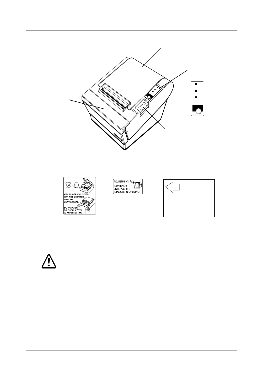
Printer Parts a nd Labels
Slide open this cutter cover
only when paper roll cover
cannot be opened.
Printer cover
Control panel
Cutter cover
Labels
Label inside
printer cover
Label inside
cutter section
POWER
ERROR
PAPER
OUT
FEED
Cover open button
Instruction label
for when cover
won’t open
POWER
ERROR
PAPER
OUT
FEED
Caution label above drawer kick-out connector.
Page 3

Quick Reference
This Quick Reference will direct you to key areas of this Operator’ s
Manual. For a complete listing of topics, see the Contents.
Printer Parts and Labels inside front cover
Ordering Paper page ix
Where to order paper
Setting Up the Printer page 1-1
How to set up the printer.
Installing and Replacing Paper page 1-7
How to load or change the paper roll.
Solving Problems page 3-1
How to correct problems.
Commands page 5-1
Descriptions of all the programming commands.
i
Page 4

All rights reserved. No part of this publication may be reproduced, stored in a
retrieval system, or transmitted in any form or by any means, electronic, mecha nical,
photocopying, recording, or otherwise, without the prior written permission of Seiko
Epson Corporation. No patent liability is assumed with respect to the use of the
information contained herein. While every precaution has been taken in the
preparation of this book, Seiko Epson Corporation assumes no responsibility for
errors or omissions. Neither is any liability assumed for damages resulting from the
use of the information contained herein.
Neither Seiko Epson Corporation nor its affiliates shall be liable to the purchaser of
this product or third parties for damages, losses, costs, or expenses incurred by
purchaser or third parties as a result of: accident, misuse, or abuse of this product or
unauthorized modifications, re pairs, or alterations to this product, or (excluding the
U.S.) failure to strictly comply with Seiko Epson Corporation’s operating and
maintenance instructions.
Seiko Epson Corporation shall not be liable against a ny damages or problems arising
from the use of any options or any consumable products other t han those desig nated
as Original Epson Products or Epson Approved Products by Seiko Epson
Corporation.
EPSON and ESC/POS are registered trademarks of Seiko Epson Corporation.
NOTICE: The contents of this manual are subject to change without notice.
Copyright © 1996 by Seiko Epson Corporation, Nagano, Japan.
ii
Page 5

FCC CLASS A
FCC Compliance Statement
For American Users
This equipment has been tested and found to comply with the limits for a Class A
digital device, pursuant to Part 15 of the FCC Rules. These limits are designed to
provide reasonable protection against harmful interference when the equipment is
operated in a commercial environment.
This equipment generates, uses, and can radiate radio frequency energy and, if not
installed and used in accordance with the instruction manual, may cause harmful
interference to radio communications. Operation of this equipment in a residential
area is likely to cause harmful interferen ce, in whic h case the user will b e required to
correct the interference at his own expense.
WARNING
The connection of a non- shielded print er interfac e cable to th is printer will i nvalidate
the FCC Verification of this device and may cause interference levels which exceed
the limits established by the FCC for this equipment.
You are cautioned that changes or modifications not expressly approved by the
party responsible for compliance could void your authority to operate the
equipment.
FOR CANADIAN USERS
This Class A digital apparatus meets all requirements of the Canadian Interfer enceCausing Equipment Regulations.
Cet appareil numérique de la classe A respecte toutes les exigenves du Règlement
sur le matériel brouileur du Canada.
GEREÄUSCHPEGEL
Gemäß der Dritten Verordnung zum Gerätesicherheitsgesetz
(Maschinenlärminformations- Verordnung-3. GSGV) ist der arbeitsplatzbezogene
Geräusch-Emissionswert kleiner als 70 dB(A) (basierend auf ISO 7779).
iii
Page 6

DECLARATION OF CONFORMITY
Product Name: Printer
Type Name: 129A
These printers conform to the following Directives and Norms
Directive 89/336/EEC
EN 55022 (1986 and 1994) Class B
EN 50082-1 (1992)
IEC 801-2 (1991)
IEC 801-3 (1984)
IEC 801-4 (1991)
Directive 90/384/EEC
EN45501: (1992)
iv
Page 7

EMI and Safety Standards Applied
The following standards are applied only to the printers that are so
labeled. (EMC is tested using the EPSON PS-170 power supply)
Europe: CE marking
EN55022
EN50082-1
EN45501
Safety Standard: TÜV (EN 60950)
North America: EMI: FCC Class A
Safety standards: UL 1950-2TH-D3
C-UL
Japan: EMI: VCCI Class 1
v
Page 8
About This Manual
Setting Up and Using
❏ Chapter 1 contains information on unpacking the printer and setting it up.
❏ Chapter 2 contains in formation on u sing the printer.
❏ Chapter 3 contains troubleshooting information.
Reference
❏ Chapter 4 contains specifications and character code tables.
❏ Chapter 5 contains the commands.
❏ Appendix A tells how to change the DIP switch and paper near end settings,
and Appendix B lists the EPSON Sales Subsidiaries and their addresses.
Warnings, Cautions, and Notes
WARNING:
Warnings must be followed carefully to avoi d serious bodily
injury.
CAUTION:
Cautions must be observed to avoid minor injury to yourself or
damage to your equipment.
Note:
Notes have important information and useful tips on the op eration of your
printer.
vi
Page 9

Introduction
Features
The TM-T88 and TM-T88P are high-quality POS printers that can print on a paper
roll. The printers have the following features:
Printing
❏ High speed printing: approximately 16.5 lines/second (1/6 inch feed).
❏ Low-noise thermal printing.
❏ High reliability due to a stable mechanism.
Application Software
❏ Command protocol is based on the ESC/POS® standard.
❏ Various layouts are possible by using page mode.
❏ Characters can be scaled up to 64 times as large as the standard size. S m oo thing
is also possible.
❏ Bar code printing is possible by using a bar code command. Bar codes can be
printed both in the vertical direction (fence bar code) and in the horizontal
direction (ladder bar code).
❏ Repeated operation and copy printing are possible by using macro definitions.
❏ Character font size (12 x 24 font or 9 x 24 font) can be selected using a command.
Printer Handling
❏ Easy paper roll loading.
❏ An auto-cutter is st andard.
❏ The printer allows easy maintenance for tasks such as head cleaning.
❏ Four different print densities can be selected by DIP switches.
❏ The built-in interface provides control capability for two drawers.
Introductionvii
Page 10

Options and Accessories
❏ EPSON power supply unit, PS-170.
❏ Affixing tapes (model : DF-10).
❏ RS-485 interface board can be equipped as a dealer option.
❏ Wall hanging bracke t se t (W H-1 0)
viii Introduction
Page 11

Ordering Paper and Supplies
Thermal roll paper can be ordered from the supplier in your area.
Specified Thermal Roll Paper: NTP080-80
In Japan: Nakagawa Seisakujo
2-5-21 Nishiki-Cho Warabi-Shi
Saitama-Ken 335 Japan
Tel: (048) 444-8211
Fax: (048) 443-6652
In U.S.A.: Nakagawa Mfg (USA) Inc.
2305 Lincoln Avenue
Hayward, CA 94545 USA
Tel: (510) 782-0197
Fax: (510) 782-7124
In Europe: Nakagawa Mfg (Europe) GmbH.
Krützpoort 16, 47804
Krefeld, Germany
Tel: 02151-711051
Fax: 02151-713293
In Southeast Asia: N.A.K. Mfg (Malaysia) SDN BHD
Lot 19-11, Bersatu Industrial Complexs,
Jalan Satu, Kaw Per. Cheras Jaya,.
Balakong Industrial Area, 43200 Cheras.
Selangor Darul Ehsan, Malaysia
Tel: 03-9047896, 9047900, 9047691
Fax: 03-9047889
Introduction ix
Page 12

Other Qualified Suppliers for Thermal Paper
The following suppliers sell thermal paper that may be used if
desired. Contact each company for information.
Original paper: TF50KS-E
Nippon Paper Industry Co., Ltd.
1-12-1, Yuraku-Cho, Chiyoda-Ku
Tokyo 100 Japan
Tel: 03-3218-8000
Fax: 03-3216-1375
Original paper: PD 160R
New Oji Paper Mfg. Co., Ltd.
7-5 Ginza 4-Chome Chuo-Ku
Tokyo 104 Japan
Tel: 03-3563-4800
Fax: 03-3563-1136
Original paper: AF50KS-E
Jujo Thermal Oy (Finland)
P.O. Box 92 FIN27501 Kauttua Finland
Original paper: F380
x Introduction
Tel: 38-3932900
Fax: 38-3932419
Kanzaki Specialty Papers, Inc.
Cummings Street
Ware, MA 01082 U.S.A.
Tel: (413)967-6204
Fax: (413) 734-5101
Page 13

Contents
Quick Reference. . . . . . . . . . . . . . . . . . . . . . . . . . . . . . . . . . . . . . . . . . . . . . . . . . . . . . . . i
Introduction . . . . . . . . . . . . . . . . . . . . . . . . . . . . . . . . . . . . . . . . . . . . . . . . . . . . . . . . . . . vii
Chapter 1 Setting Up the Printer
Unpacking . . . . . . . . . . . . . . . . . . . . . . . . . . . . . . . . . . . . . . . . . . . . . . . . . . . . . . . . . . . . 1-1
Connecting the Cables and Grounding the Printer . . . . . . . . . . . . . . . . . . . . . . . . . . 1-2
Installing or Replacing the Paper Roll . . . . . . . . . . . . . . . . . . . . . . . . . . . . . . . . . . . . . 1-7
Using the Power Switch Cover . . . . . . . . . . . . . . . . . . . . . . . . . . . . . . . . . . . . . . . . . . . 1-10
Self Test . . . . . . . . . . . . . . . . . . . . . . . . . . . . . . . . . . . . . . . . . . . . . . . . . . . . . . . . . . . . . . 1-10
Running the self test . . . . . . . . . . . . . . . . . . . . . . . . . . . . . . . . . . . . . . . . . . . . . . . 1-10
Adjustments and Settings . . . . . . . . . . . . . . . . . . . . . . . . . . . . . . . . . . . . . . . . . . . . . . . 1-12
Chapter 2 Using the Printer
Operating the Control Panels . . . . . . . . . . . . . . . . . . . . . . . . . . . . . . . . . . . . . . . . . . . . 2-1
Control Panel . . . . . . . . . . . . . . . . . . . . . . . . . . . . . . . . . . . . . . . . . . . . . . . . . . . . . 2-1
Panel Lights . . . . . . . . . . . . . . . . . . . . . . . . . . . . . . . . . . . . . . . . . . . . . . . . . . . . . . . 2-2
Chapter 3 Troubleshooting
Troubleshooting . . . . . . . . . . . . . . . . . . . . . . . . . . . . . . . . . . . . . . . . . . . . . . . . . . . . . . . 3-1
General problems . . . . . . . . . . . . . . . . . . . . . . . . . . . . . . . . . . . . . . . . . . . . . . . . . . 3-1
Printing problems . . . . . . . . . . . . . . . . . . . . . . . . . . . . . . . . . . . . . . . . . . . . . . . . . . 3-1
Cleaning the print head . . . . . . . . . . . . . . . . . . . . . . . . . . . . . . . . . . . . . . . . . . . . . 3-3
Paper handling problems . . . . . . . . . . . . . . . . . . . . . . . . . . . . . . . . . . . . . . . . . . . 3-3
Auto cutter problems . . . . . . . . . . . . . . . . . . . . . . . . . . . . . . . . . . . . . . . . . . . . . . . 3-5
Hexadecimal Dump . . . . . . . . . . . . . . . . . . . . . . . . . . . . . . . . . . . . . . . . . . . . . . . . . . . . 3-7
xi
Page 14

Chapter 4 Reference Information
Printing Specifications . . . . . . . . . . . . . . . . . . . . . . . . . . . . . . . . . . . . . . . . . . . . . . . . . . 4-1
Paper Specifications . . . . . . . . . . . . . . . . . . . . . . . . . . . . . . . . . . . . . . . . . . . . . . . . . . . . 4-3
Electrical Characteristics . . . . . . . . . . . . . . . . . . . . . . . . . . . . . . . . . . . . . . . . . . . . . . . . 4-4
Reliability . . . . . . . . . . . . . . . . . . . . . . . . . . . . . . . . . . . . . . . . . . . . . . . . . . . . . . . . . . . . . 4-5
Environmental Conditions . . . . . . . . . . . . . . . . . . . . . . . . . . . . . . . . . . . . . . . . . . . . . . 4-5
Character Code Tables . . . . . . . . . . . . . . . . . . . . . . . . . . . . . . . . . . . . . . . . . . . . . . . . . . 4-6
Chapter 5 Commands
Command Notation . . . . . . . . . . . . . . . . . . . . . . . . . . . . . . . . . . . . . . . . . . . . . . . . . . . . 5-1
Control Commands . . . . . . . . . . . . . . . . . . . . . . . . . . . . . . . . . . . . . . . . . . . . . . . . . . . . 5-1
Appendix A DIP Switch and Paper Near End Settings
Setting the DIP Switches . . . . . . . . . . . . . . . . . . . . . . . . . . . . . . . . . . . . . . . . . . . . . . . . A-1
Adjusting the Paper Near End Sensor . . . . . . . . . . . . . . . . . . . . . . . . . . . . . . . . . . . . . A-8
Appendix B EPSON Sales Subsidiaries
xii
Page 15
Chapter 1
Setting Up the Printer
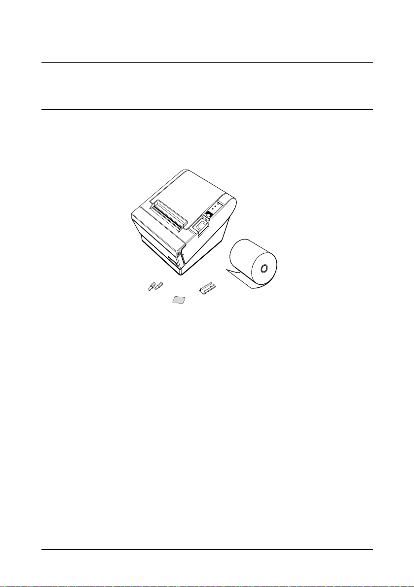
Unpacking
Your printer box should include these items. If any items are
damaged or missing, please contact your dealer for assistance.
Printer
POWER
ERROR
PAPER
OUT
FEED
Paper roll
Hexagonal
lock screws
Switch cover
Instruction label for
when paper roll cover
cannot be opened
See the note on page 1-3 for information abou t the hexag o na l lo ck screws.
Setting Up the Printer 1-1
Page 16

Connecting the Cables and Grounding the Printer
You can connect up to four c ables to the print er. The y a ll connect to
the connector panel on the back of the printer, which is shown
below:
FG
Interface
Grounding screw
FG
Drawer kick-out
DC24V
DK
Power supply
Notes:
There is a caution label above the drawer kick-out connector.
Depending on the interface installed, the interface connector on
your printer may look different from the one illustrated.
Before connecting any of the cables, make sure that both the printer
and the computer are turned off.
Connecting the compu t er
You need an appropriate interface cable.
1. Plug the cable connector securely into the printer’s interface
connector.
2. Tighten the screws on both sides of the cable connector.
1-2 Setting Up the Printer
Page 17
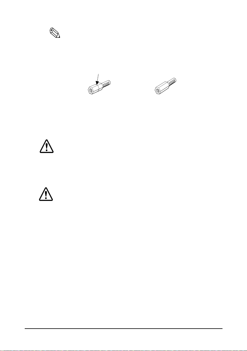
Note:
Your printer has inch-type hexagonal lock screws installed. If
your interface cable requires millimeter-type screws, replace the
inch-type screws with the enclosed millimeter-type screws using
a hex screwdriver (5 mm).
Inch screw
3. Attach the other end of the cable to the computer.
Millimeter screw
Connecting the Drawer
WARNING:
Use a drawer that matches th e prin te r sp eci ficat ion . Usi ng a n
improper drawer may damage the drawer as well as the
printer.
CAUTION:
Do not connect a telephone line to the drawer kick-out
connector; otherwise the printer and the telephone line may
be damaged.
Setting Up the Printer 1-3
Page 18
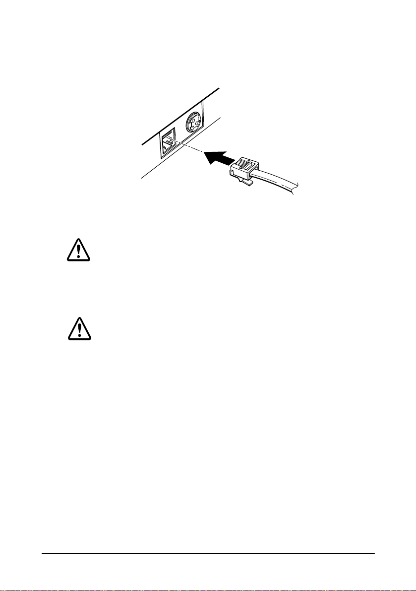
Plug the drawer cable into the drawer kick-out connector on the
back of the printer next to the power supply connector.
Anschließen der Lade
WARNUNG:
Eine für den Drucker geeignete Lade verwenden. Bei
Verwendung einer falschen Lade kann diese oder der
Drucker beschädigt werden.
ACHTUNG:
Kein Telefonkabel an die Schnappsteckerbuchse
anschließen, da sonst der Drucker und die Telef onkabel
beschädigt werden können.
1-4 Setting Up the Printer
Page 19

Das Kabel der Lade an die Schnappsteckerbuchse hinten am
Drucker neben dem Netßzanschluß
anschließen
.
Grounding the Printer
You need a ground wire to ground your printer. Make sure that the
wire is AWG 18 or equivalent.
1. Make sure that the printer is turned off.
2. Connect the ground wire to the printer using one of the the FG
screws on the back of the printer, as shown.
FG
FG
DC24V
DK
Connecting the Power Supply
Use the optional EPSON PS-170 or equivalent power supply for
your printer.
Setting Up the Printer 1-5
Page 20

WARNING:
Make sure that you use the EPSON PS-170 power supply or
equivalent. Usi ng an incorrect power supply may c ause fire or
electrical shock.
CAUTIONS:
When connecting or disconnecting the power supply from
the printer, make sure that the power supply is not plugged
into an electrical outlet. Otherwise you may damage the
power supply or the printer.
If the power supply’s rated voltage and your outlet’s voltage
do not match, contact your dealer for assistance. Do not
plug in the power cord. Otherwise, you may damage the
power supply or the printer.
1. Make sure that the printer’s power switch is turned off, and the
power supply’s power cord is unplugged from the electrical
outlet.
2. Check the label on the power supply to make sure that the
voltage required by the power supply matches that of your
electrical outlet.
3. Plug in the power supply’s cable as shown below. Notice that
the flat side of the plug faces down.
Note:
To remove the DC cable connector, make sure that the power
supply’s power cord is unplugged; then grasp the connector at the
arrow and pull it straight out.
1-6 Setting Up the Printer
Page 21

Installing or Replacing the Paper Roll
Note:
Be sure to use paper rolls that meet the specifications. Do not
use paper rolls that have the paper glued to the core because the
printer cannot detect the paper end correctly.
1. Make sure that the printer is not recei ving data; otherwi se, data
may be lost.
2. Open the paper roll cover by pressi ng the cove r-open butto n. If
the cover-open button will not open the cover, see page 3-4 or
3-6 in Troubleshooting.
POWER
ERROR
PAPER
OUT
FEED
3. Remove the used paper roll core if there is one.
Setting Up the Printer 1-7
Page 22
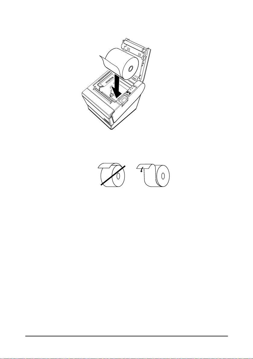
4. Insert the paper roll as shown.
POWER
ERROR
PAPER
OUT
FEED
5. Be sure to note the correct direction that the paper comes off the
roll.
1-8 Setting Up the Printer
Page 23

6. Pull out a small amount of paper, as shown. Then close the
cover.
POWER
ERROR
PAPER
OUT
FEED
7. Tear off the paper as shown.
POWER
ERROR
PAPER
OUT
FEED
Setting Up the Printer 1-9
Page 24

Using the Power Switch Cover
WARNING:
If an accident occurs when the power switch cover is
attached, unplug the power supply cord from the outlet
immediately. Continued usage may lead to fire or shock.
You can use the enclosed power swi tch cove r t o mak e sure that the
power switch is not accidentally pressed. If you want to use this
cover, install it as shown in the illustra tion below.
POWER
ERROR
PAPER
OUT
FEED
Self Test
The self test lets you know if your printer is operating properly. It
checks the control circuits , printer mechanisms, print quality, ROM
version, and DIP switch settin gs.
This test is independent of any other equipment or software.
Running the self test
1. Make sure the printer is turned off and the printer covers are
closed properly.
1-10 Setting Up the Printer
Page 25

2. While holding down the FEED button, turn on the printer using
the switch on the front of the printer to begin the self test. The
self test prints the printer settings and then prints the
following, cuts the paper, and pauses. (The PAPER OUT light
blinks.)
Self test printing.
Please press the PAPER FEED button.
3. Press the FEED button to continue printing. T he print er pri nts a
pattern using the built-in character set.
4. The self test automatically ends and cuts the paper after
printing the following:
*** completed ***
The printer is ready to receive data as soon as it completes the self
test.
Note:
If you want to pause the self test manually, press the FEED
button. Press the FEED button again to continue the self test.
Setting Up the Printer 1-11
Page 26

Adjustments and Settings
The TM-T88/T88P is set up at the factory to be appropriate for
almost all users. It does, however, offer some settings for users with
special requirements.
It has DIP switches that allow you to change communication
settings, such as handshaking and parity check, as well as print
density.
The TM-T88/T88P also has a near-end sensor for the paper. This
can give you a warning when the paper is almost out. If you find
that there is not en ough pap er remai ning on the roll when the nearend detector is triggered, you can change the near-end sensor
setting.
See Appendix A if you need to make any of these changes.
1-12 Setting Up the Printer
Page 27

Using the Printer
Chapter 2
Operating the Control Panels
You can control the basic paper feeding operations of the printer
with the button on the control panel. The indicator lights help you
monitor the printer’s status.
Control Panel
POWER
ERROR
PAPER
OUT
FEED
Button
The button can be disabled by the ESC c 5 command.
Press the FEED button onc e to ad vance pa per one l in e. You ca n also
hold down the FEED button to feed paper continuously.
Using the Printer 2-1
Page 28

Panel lights
POWER
The POWER light is on whenever the printer is on.
ERROR
This indicates an error. See Chapter 3 for informati on on what to do
when this light comes on.
PAPER OUT
This light in dicates the near end of the pape r roll. Install a new
paper roll and the printer will continue pr inting.
When the light blinks, it indicates the self-test printing standby
state or macro execution standby state when the macro execution
command is used.
2-2 Using the Printer
Page 29

Chapter 3
Troubleshooting
Troubleshooting
This chapter gives solutions to so me printer problems you may
have.
General problems
The lights on the control pane l do not come on.
Make sure that the power supply cables are correctly plugged into
the printer, the power unit, and to the pow er outlet.
Make sure that power is s upplied to the power outlet. If the outle t
is controlled by a switch or timer, use another outlet.
Printing problems
The ERROR light is on (not blinking) and nothing is printed.
If the PAPER OUT light is on, the paper roll is not installed or is at
or near the end. Install a new paper roll. See Chapter 1 for
instructions.
If the PAPER OUT light is off, make sure that the printer cover is
properly closed. Press the printer cover until the cover audibly
clicks into place.
The ERROR light is blinking and the printer does not print.
First, turn off the printer and check for a paper jam. (See the paper
jam description on page 3-3.)
Troubleshooting 3-1
Page 30

If there is no paper jam and the printer has been printi ng for quite a
while, the print head may be overheated. If the print head is
overheated, the printer will resume printing when the head has
cooled (usually within two or three minutes).
If there is no paper jam and the print head is not overheated, turn
off the printer and turn it back on after about 10 seconds. If the
ERROR light is still flashing, contact a qualified service person.
The ERROR light is off, but nothing is printed.
Try to run the self test to check that the printer works proper ly. See
the self test instructions in Chapter 1 to run the self test. If the self
test does not work, contact your dealer or a qualified service
person.
If the self test works properly, check the following:
1. Check the connection at both ends of the interface cable
between the printer and the computer. Also make sure that this
cable meets the specifications for both the printer and the
computer.
2. The data transmission settings may be different between the
printer and co mputer. Make sure that the printer’s DIP switch
settings for data transmission are the same as the computer’s.
You can print the printer’s interface settings using the self test.
If the printer still does not print, contact your dealer or a qualified
service person.
Printing is poor.
Paper dust on the heating element of the thermal print head can
lower the pr int quality. Try cleaning the print head as described
below:
3-2 Troubleshooting
Page 31

Cleaning the print head
CAUTIONS:
After printing, the print head can be very hot. Be careful not
to touch it. Also let it cool before you clean it.
Do not damage the print head by touching it with your
fingers or any hard object.
1. Open the printer cover.
2. Clean the thermal element of the print head with a cott on swab
moistened with an alcohol solvent (ethanol, methanol, or IPA).
Radiation plate
Head
Thermal element
Paper handling problems
Paper is jammed inside the printer.
CAUTIONS:
Do not touch the print head because it ca n b e ve ry ho t after
printing continuously for a long time.
Troubleshooting 3-3
Page 32

To clear a paper jam, follow the steps below:
1. Turn the printer off and press the cover open button to open
the cover.
2. Remove the jammed paper and put the roll back in the printer
and close the cover.
3. If paper is caught in the automatic cutter and the printer cover
cannot be opened, open the cutter cover as shown below.
POWER
ERROR
PAPER
OUT
FEED
3-4 Troubleshooting
Page 33

4. Then turn the knob until you see in the opening, as shown in
the illustrati on below. This returns the cutter bl ade to the
normal position. Also notice that there is a label near the cutter
to assist you.
ADJUSTMENT:
TURN KNOB
UNTIL YOU SEE
TRIANGLE IN OPENING
POWER
ERROR
PAPER
OUT
FEED
5. Close the cutter cover.
6. Open the printer cover.
7. Remove the jammed paper.
Auto cutter problems
The auto cutter is jammed.
If a foreign object such as a push pi n or pap er cli p dro ps in the auto
cutter and causes the auto cutter to lock up, the printer enters an
error state and begins the recovery operation automatically.
If the problem is not serious, the auto cutter returns to its normal
position without any intervention by th e user.
Troubleshooting 3-5
Page 34

If the auto cutter does not return to its normal position by itself,
follow the steps below to corre ct the problem:
1. Pull the cutter cover toward you so that you can rotate the
cutter motor knob.
POWER
ERROR
PAPER
OUT
FEED
2. Following the instructions on the label, rotate the knob until the
appears in the hole.
ADJUSTMENT:
TURN KNOB
UNTIL YOU SEE
TRIANGLE IN OPENING
3. Close the cutter cover.
3-6 Troubleshooting
POWER
ERROR
PAPER
OUT
FEED
Page 35

Hexadecimal Dump
This feature allows experienced users to see exactly what data is
coming to the printer. This can be useful in finding software
problems. When you turn on the hex dump function, the printer
prints all commands and other data in hexadecimal format along
with a guide section to help you find specific commands.
To use the hex dump feature, follow these steps:
1. After you make sure that the printer is off, open the cover.
2. Hold down the FEED button while you turn on the printer.
3. Close the cover.
4. Run any software program that sends data to the printer. The
printer prints “Hexadecimal Dump” and then all the codes it
receives in a two-column format. The first column contains the
hexadecimal codes and the second column gives the ASCII
characters that correspond to the codes.
Hexadecimal Dump
1B 21 00 1B 26 02 40 40 . ! . . & . @ @
1B 25 01 1B 63 34 00 1B . % . . c4 . .
41 42 43 44 45 46 47 48 ABCDEFGH
❏ A period (.) is printed for each code that has no ASCII
equivalent.
❏ During the hex dump all commands except DLE EOT and
DLE ENQ are disabled.
5. Open the cover to set the printer off line so that it will print the
last line.
6. Close the cover and turn of f the printe r or reset i t to turn off the
hex dump mode.
Troubleshooting 3-7
Page 36

Chapter 4
Reference Information
Printing Specifications
Printing method: Thermal line printing
Dot density: 180 dpi
25.4 mm (1”)]
Printing direction: Unidirectional with friction feed
Printing width: 72 mm (2.83”), 512 dot positions
Characters per line
(default):
Character spacing
(default):
Printing speed - High: Approximately 16.5 lines/second
Printing speed - Low: Approximately 11.8 lines/second (1/6”
42 (Font A)
56 (Font B)
0.28 mm (.01”) (2 dots) (Font A)
0.28 mm (.01”) (2 dots) (Font B)
Programmable by control command.
(1/6” inch feed, at 24V, 20° C,
density level 2)
Approximately 70 mm/second
(approximately 2.76”/second)
feed)
Approximately 50 mm/second
(approximately 2.0”/second)
High and low speeds are switched
automatically depending on the voltage
applied to the print er and t he temperat ure
of the environment.
Approximately 28 mm/second
(approximately 1.1”/second) when a
ladder bar code is printed.
×
180 dpi [the number of dots per
Reference Information 4-1
Page 37

Notes:
Printing speed may be slower, depending on the data transmission
speed and the combination of control commands.
The printer switches the mode of the printing speed automatically.
There may be variations in printing after switching the mode of the
printing speed. To prevent this for logo printing, using a
downloaded bit image is recommended. (Change in printing speed
does not occur during downloaded bit image printing).
Paper feeding speed: Approximately 70 mm/second
(approximately 2.76”/second) continuous
printing
Line spacing (default): 4.23 mm (1/6”)
Programmable by control command.
Number of characters: Alphanumeric characters: 95
International characters: 32
Character structure: Font A: 12
4-2 Reference Information
Extended graphics: 128
×
(including one space page)
×
24 (including 2-dot spacing
in horizontal)
Font B: 9
×
24 (including 2-dot spacing in
horizontal)
Font A is the default
7 pages
Page 38

CPL
80±
mm 3.15±
2
4
21
28
Double-width/
Double-height
W x H
(mm)
2.82 x 6.77
(.11” x .27”)
1.98 x 6.77
(.08” x .27”)
Standard Double-height Double-width
W x H
(mm)
Font A
12 x 24
Font B
9 x 24
* CPL = Characters Per Line
* Space between characters is not included
* Characters can be scaled up to 64 times as large as the standard sizes.
1.41 x 3.39
(.06” x .13”)
0.99 x 3.39
(.04” x .13”)
CPL
42
56
W x H
(mm)
1.41 x 6.77
(.06” x .27”)
0.99 x 6.77
(.04” x .27”)
CPL
42
56
W x H
(mm)
2.82 x 3.39
(.11” x .13”)
1.98 x 3.39
(.08” x .13”)
Paper Specifications
Paper roll (single-ply): Size: Width: 79.5 mm ± 0.5 mm
(3.13” ± 0.02”)
CPL
21
28
Maximum
83 mm (3.27”)
outside
diameter:
Paper roll
spool
diameter:
Inside: 12 mm (0.47”)
Outside: 18 mm (0.71”)
Paper must not be pasted
to the paper roll spool.
Take up
paper roll
0.5
1.0
0.0
0.0
width:
Reference Information 4-3
Page 39

Electrical Characteristics
Supply voltag e: +24 VDC ± 7% (optional power supply: EPSON
PS-170)
Current
consumption: (at
24V, except for
drawer kick-out
driving)
Note:
Maximum 1A for drawer kick-out driving
Operating: Mean: approximately 1.5A
Standby: Mean: approximately 0.2A
(character font A α-N, capital
letters, 36-character rolling pat tern,
42 columns printing)
Peak: Approximately 5.0 A
4-4 Reference Information
Page 40

Reliability
Life: Mechanism: 15,000,000 lines
Thermal head: 100 million pulses,
100 km
Auto cutter: 1,000,000 cuts
(End of Life is defined as the point at
which the printer reaches the beginning of
the Wearout Period.)
MTBF: 180,000 hours
(Failure is defined as Random Failure
occurring at the time of the Random
Failure Period.)
MCBF: 37,000,000 lines
(This is an average failure interval based
on failures relating to wearout and
random failures up to the life of 15 mill io n
lines.)
Environmental Conditions
Temperature: Operating: 5° to 45°C (41° to 113°F)
Storage: -10° to 50°C (14° to 122°F)
(except for paper)
Humidity: Operating: 10 to 90% RH
Storage: 10 to 90% RH (except for
paper)
Reference Information 4-5
Page 41

Character Code Tables
The following pages show the character code tables. To find the
character corresponding t o a hexadecimal number, co unt across the
top of the table for the left digit and count down the left column of
the table for the right digit. For example, 4A = J.
Page 0 (PC437: U.S.A., Standard Europe)
(International character set: U.S.A.)
Note:
The character code tables show only which characters are printed.
They do not show the actual print pattern.
4-6 Reference Information
Page 42

Page 1 (Katakana)
Reference Information 4-7
Page 43

Page 2 (PC850: Multilingual)
4-8 Reference Information
Page 44

Page 3 (PC860: Portuguese)
Reference Information 4-9
Page 45

Page 255 (Space Page)
4-12 Reference Information
Page 46

International character set
ASCII code
Country
U. S.A. # $ @[ \
Fr a nce # $ à ° ç § ^ ` é ù è ¨
Germ a ny # $ § Ä Ö Ü ^ ` ä ö ü ß
U.K. £ $ @
Den mark I # $ @ Æ Ø Å ^ ` æ ø å
Swe den # ¤ É Ä Ö Å Ü é ä ö å ü
It a ly # $ @ ° \ é ^ ù à ò è ì
Sp ai n Pt $ @ ¡ Ñ ¿ ^ ` ¨ ñ }
Japan # $ @
Nor way # ¤ É Æ Ø Å Ü é æ ø å ü
Den mar k I I # $ É Æ Ø Å Ü é æ ø å ü
Hex 23 24 40 5B 5C 5D 5E 60 7B 7C 7D 7E
Dec 35 36 64 91 92 93 94 96 123 124 125 126
^` { ¦ }
]
\
[
¥
[
^` { ¦ }
]
^` { ¦ }
]
~
~
~
~
~
Reference Information 4-13
Page 47

Chapter 5
Commands
Command Notation
[Name] The name of the command.
[Format] The code sequence.
[Range] Gives the allowable ranges for the arguments.
[Description] Describes the function of the command.
Explanation of Terms
LSB Least Significant Bit
Control Commands
HT
[Name] Horizontal tab
[Format] ASCII HT
[Description] Moves the print position to the next horizontal tab position.
ASCII indicates the ASCII equivalents.
Hex indicates the hexadecimal equivalents.
Decimal indicates the decimal equivalents.
[ ]k indicates the contents of the [ ] should be repeated k times.
Hex 09
Decimal 9
LF
[Name] Print and line feed
[Format] ASCII LF
Hex 0A
Decimal 10
[Description] Prints the data in the print buffer an d f eeds o ne line based on the current
line spacing.
Commands 5-1
Page 48

FF
[Name] Print and return to standard mode (in page mode)
[Format] ASCII FF
Hex 0C
Decimal 12
[Description] In page mode, prints the data in the print buffer collectively and returns
to standard mo de .
CR
[Name] Print and carriage return
[Format] ASCII CR
Hex 0D
Decimal 13
[Description]
Paper
Paper roll Functions as same as LF Ignored
When automatic line feed
enabled
• This comma nd is se t acc ording to the DIP switch 1-1 setting at
power-on or re setting the pr inter with a para llel interface .
Automatic line feed disabled
CAN
[Name] Cancel print data in page mode
[Format] ASCII CAN
Hex 18
Decimal 24
[Description] In page mode, deletes all the print data in the current printable area.
DLE EOT
[Name] Real-time stat us tr an sm ission
[Format] ASCII DLE EOT
[Range] 1 ≤ n ≤ 4
n
Hex 10 04
Decimal 16 4
n
n
n
5-2 Commands
Page 49

[Description] Transmits the selected printer status specified by n in real time, according
to the following parameters:
n
= 1: Transmit printer status
n
= 2: Transmit off-line status
n
= 3: Transmit error status
n
= 4: Transmit paper roll sensor status
DLE ENQ
[Name] Real-time request t o prin t er
[Format] ASCII DLE ENQ
[Range] 1 ≤ n ≤ 2
[Description] Responds to a request from the host computer. n specifies the request as
nRequest
1 Recover from an error and restart printing from the line where the error occurred
2 Recover from an error after clearing the receive and print buffers
n
Hex 10 05
Decimal 16 5
follows:
n
n
n
ESC FF
[Name] Print data in page mode
[Format] ASCII ESC FF
Hex 1B 0C
Decimal 27 12
[Description] In p a g e mode, prints all b u ffe re d data in the prin ting area collectively.
ESC SP
[Name] Set right-side character spacing
[Format] ASCII ESC SP
[Range] 0 ≤ n ≤ 255
[Description] Sets the character spacing for the right side of the character to [n ×
n
Hex 1B 20
Decimal 27 32
horizontal or vertical motion units].
n
n
n
Commands 5-3
Page 50

ESC !
n
[Name] Select print mode(s)
[Format] ASCII ESC !
Hex 1B 21
Decimal 27 33
[Range] 0 ≤ n ≤ 255
[Description] Selects print mode(s) using n as follows:
Bit Off/On Hex Decimal Function
Off 00 0 Character font A (12 x 24).
0
On 01 1 Character font B (9 x 24).
1, 2 - - - Undefined.
Off 00 0 Emphasized mode not selected.
3
On 08 8 Emphasized mode selected.
Off 00 0 Double-height mode not selected.
4
On 10 16 Double-height mode selected.
Off 00 0 Double-width mode not selected.
5
On 20 32 Double-width mode selected.
6 - - - Undefined.
Off 00 0 Underline mode not selected.
7
On 80 128 Underline mod e selected.
n
n
n
• Determine the values of n by adding the values of all the
characteristics you w an t to se le c t .
ESC $
n
L nH
[Name] Set absolute print position
[Format] ASCII ESC $
Hex 1B 24
Decimal 27 36
0 ≤
n
n
≤ 255
L
≤ 255
H
[Range] 0 ≤
[Description] Sets the print starting position from the beginning of the line.
• The distance from the beginning of the line to the print
n
n
+
position is [(
× 256) × (vertical or horizontal motion
L
H
unit)].
5-4 Commands
n
n
n
L nH
L nH
L nH
Page 51

ESC %
[Name] Select/cancel user-defined character set
[Format] ASCII ESC %
[Range] 0 ≤ n ≤ 255
[Description] Selects or cancels the user-defined character set.
n
Hex 1B 25
Decimal 27 37
• When the LSB is 0, the user-defined character set is canceled
and the internal char act er se t is se le cted.
• When the LSB is 1, the user-defined character set is selected.
n
n
n
ESC &
[Name] Define user-define d ch ara ct ers
[Format] ASCII ESC &
[Range]
[Description] Defines user-defined characters.
y c1 c2 [x1 d1...d(y
Hex 1B 26
Decimal 27 38
y
= 3
32 ≤ c1 ≤ c2 ≤ 126
0 ≤ x ≤ 12 Font A (12 × 24)
0 ≤ x ≤ 9 Font B (9 × 24)
0 ≤
d1 ... d(y
×
xk)
×
x1)]...[xk d1...d(y × xk)]
y c1 c2 [x1 d1...d(y
[xk d1...d(y
y c1 c2 [x1 d1...d(y
[xk d1...d(y
y c1 c2 [x1 d1...d(y
[xk d1...d(y
≤ 255
•y specifies the number of bytes in the vertical direction.
•c1 specifies the beginning character code for the definition, and
c2
specifies the final code.
•x specifies the number of dots in the horizontal direction.
•d is the dot data for the characters. The dot pattern is in the
horizontal direction from the left side. Any remaining dots on
the right side are blank.
• The allowab le character code rang e is from ASCII code
20H(32) to 7EH(126).
• The data to defi ne a use r-defined character is
(y × x) bytes.
• Set a corresponding bit to 1 to print a dot o r 0 to not print a do t.
×
x1)]...
xk)]
×
x1)]...
×
xk)]
×
×
x1)]...
xk)]
×
Commands 5-5
Page 52

m n
L nH
d1 ...
dk
ESC ✻
[Name] Select bit -image mode
[Format] ASCII ESC *
Hex 1B 2A
Decimal 27 42
n
L
n
H
m
≤ 255
≤ 3
= 0, 1, 32, 33
[Range]
0 ≤
0 ≤
m n
m n
m n
L nH
L nH
L nH
d1 ...
d1 ...
d1 ...
k
k
k
0 ≤ d ≤ 255
[Description] Selects a bit-image mode using m for the number of dots specified by
n
n
and
L
mMode
0 8-dot single-density 8 60 DPI 90 DPI n
1 8-dot double-density 8 60 DPI 180 DPI n
32 24-dot single-density 24 180 DPI 90 DPI (n
33 24-dot double-density 24 180 DPI 180 DPI (n
, as follows:
H
•The
Vertical Direction Horizontal direction
n
and
L
Number of
Dots
n
indicate the number of dots of the bit image in
H
Dot
Density
Dot
Density
Number of Data
(K)
L
+ nH × 256
L
+ nH × 256
L
+ nH × 256) × 3
L
+ nH × 256) × 3
the horizontal direction. The number of dots is calculated by
n
n
+
× 256.
L
H
• If the bit-image data input exceeds the number of dots to be
printed on a line , t he e xcess data is ignored.
•d indicates the bit-image data. Set a corresponding bit to 1 to
print a dot or to 0 to not print a dot.
ESC - n
[Name] Turn underl in e mode on/off
[Format] ASCII ESC -
Hex 1B 2D
Decimal 27 45
n
n
n
[Range] 0 ≤ n ≤ 2, 48 ≤ n ≤ 50
[Description] Turns under line mode on or off, based on th e fo llowing values of n:
n Function
0, 48 Turns off underline mode
1, 49 Turns on underline mode (1-dot thick)
2, 50 Turns on underline mode (2-dots thick)
5-6 Commands
Page 53

ESC 2
[Name] Select default line spacing
[Format] ASCII ESC 2
Hex 1B 32
Decimal 27 50
[Description] Sets the line spacing to 1/6 inch.
ESC 3
n
[Name] Set line spacing
[Format] ASCII ESC 3
Hex 1B 33
Decimal 27 51
[Range] 0 ≤ n ≤ 255
[Description] Sets the line spacing to [n × vertical or horizontal motion unit].
ESC =
n
[Name] Set peripheral device
[Format] ASCII ESC =
Hex 1B 3D
Decimal 27 61
[Range] 1 ≤ n ≤ 255
[Description] Selects device to which host computer sends data, using n as follows:
Bit Off/On Hex Decimal Function
Off 00 0 Printer disabled.
0
On 01 1 Printer enabled
1-7 - - - Undefined.
n
n
n
n
n
n
ESC ?
n
[Name] Cancel user-defined characters
[Format] ASCII ESC ?
Hex 1B 3F
Decimal 27 63
[Range] 32 ≤ n ≤ 126
[Description] Cancels user-defined characters.
n
n
n
ESC @
[Name] Initialize printer
[Format] ASCII ESC @
Hex 1B 40
Decimal 27 64
[Description] Clears the data in the print buffer and resets the printer mode to the
mode that was in effect wh en t he p ow e r was turned on.
Commands 5-7
Page 54

ESC D n1 ... nk NUL
[Name] Set horizontal tab positions
[Format] ASCII ESC D
Hex 1B 44
Decimal 27 68
[Range] 1 ≤ n ≤ 255
0≤ k ≤ 32
[Description] Sets horizontal tab posit io n s.
•n specifies the column number for setting a horizontal tab
position from the beginning of the line.
•k indicates the total n umber of horizontal tab positi on s t o b e
set.
ESC E
n
[Name] Turn emphasized mode on/off
[Format] ASCII ESC E
Hex 1B 45
Decimal 27 69
[Range] 0 ≤ n ≤ 255
[Description] Turns emphasized mode on or off
• When the LSB is 0, emphasized mode is turned off.
• When the LSB is 1, emphasized mode is turned on.
ESC G
[Name] Turn double-strike mode on/off
[Format] ASCII ESC G
[Range] 0 ≤ n ≤ 255
[Description] Turns double -strike mode on or off.
ESC J
[Name] Print and feed paper
[Format] ASCII ESC J
[Range] 0 ≤ n ≤ 255
[Description] Prints the data in the pri nt b u ffe r an d fe eds t h e pape r n × vertical or
n
Hex 1B 47
Decimal 27 71
• When the LSB is 0, double-strike mode is tur ned off.
• When the LS B is 1, double-strike mode is turned on.
n
Hex 1B 4A
Decimal 27 74
horizontal motion unit.
n
1 ... nkNUL
n
1 ... nk00
n
1 ... nk0
n
n
n
n
n
n
n
n
n
5-8 Commands
Page 55

ESC L
[Name] Select page mode
[Format] ASCII ESC L
Hex 1B 4C
Decimal 27 76
[Description] Switches from st an d ard mode to page mode.
ESC R
n
[Name] Select an intern at ion al character set
[Format] ASCII ESC R
Hex 1B 52
Decimal 27 82
[Range] 0 ≤ n ≤ 10
[Description] Selects an in t e rnational character set n from the following t able:
nCharacter set
0 U.S.A.
1France
2Germany
3U.K.
4Denmark I
5 Sweden
6Italy
7 Spain
8 Japan
9 Norway
10 Denmark II
n
n
n
ESC S
[Name] Select standard mode
[Format] ASCII ESC S
Hex 1B 53
Decimal 27 83
[Description] Switches from page mode to standard mode.
ESC T
n
[Name] Select print direction in page mode
[Format] ASCII ESC T
Hex 1B 54
Decimal 27 84
[Range] 0 ≤ n ≤ 3
48 ≤ n ≤ 51
[Description] Selects the print direction and starting position in page mode.
n
n
n
Commands 5-9
Page 56

n
specifies the print direction an d starting position as follows:
n Print Direction Starting Position
0, 48 Left to right Upper left
1, 49 Bottom to top Lower left
2, 50 Right to left Lower right
3, 51 Top to bottom Upper right
ESC V
n
[Name] Turn 90° clockwise rotation mode on/off
[Format] ASCII ESC V
Hex 1B 56
Decimal 27 86
n
n
n
[Range] n = 0, 1, 48, 49
[Description] Turns 90° clockwise rotation mode on/off
n
is used as follows:
n Function
0, 48 Turns off 90° clockwise rotation mode
1, 49 Turns on 90° clockwise rotation mode
ESC W
L xH yL yH
x
dxL dxH dyL dy
H
[Name] Set printing area in page mode
[Format] ASC II ESC W
Hex 1B 57
Decimal 27 87
x
, xH, yL, yH, dxL, dxH, dyL, dy
[Range] 0 ≤
L
(except
dx
=dxH=0 or dyL=dyH=
L
H
0)
x
L xH yL yH
x
L xH yL yH
x
L xH yL yH
≤ 255
dxL dxH dyL dy
dxL dxH dyL dy
dxL dxH dyL dy
H
H
H
[Description] • The horizontal starting position, vertical starting position,
printing area width, and prin ting a rea h eight are defin ed as x0 ,
y0, dx, dy, respectively.
Each setting for the printing area is calculated as fol lows:
x
x
L
H
+
x0 = [(
y0 = [(
dx = [
dy = [
( 256) × (horizontal motion unit)]
y
y
L
H
+
( 256) × (vertical mo t ion unit)]
dx
dx
L
H
+
( 256) × (horizontal motion unit)]
dy
dy
L
H
+
( 256) × (vertical motion unit)]
5-10 Commands
Page 57

ESC \
nL nH
[Name] Set relative print position
n
n
n
L nH
L nH
L nH
[Format] ASCII ESC \
Hex 1B 5C
Decimal 27 92
n
[Range] 0 ≤
0 ≤
L
n
H
≤ 255
≤ 255
[Description] Sets the print starting position based on the current position.
• This command set s th e di st ance from the current pos it ion to [(
n
H
× 256) × horizontal or vertical motion unit]
ESC a
n
[Name] Select justification
[Format] ASCII ESC a
Hex 1B 61
Decimal 27 97
n
n
n
[Range] 0 ≤ n ≤ 2, 48 ≤ n ≤ 50
[Description] Aligns all the data in one lin e to t h e specified position
n
selects the justifica t ion as follows
n Justification
0, 48 Left justification
1, 49 Center i ng
2, 50 Right justification
:
n
L
+
ESC c 3
n
[Name] Select paper sensor(s) to output paper end signals
[Format] ASCII ESC c 3
Hex 1B 63 33
Decimal 27 99 51
n
n
n
[Range] 0 ≤ n ≤ 255
[Description] Selects the paper sensor(s) to output paper end signals
This command is available only with a parallel inte rface and is ignored with ser ial
interface.
• Each bit of n is used as follows:
Bit Off/On Hex Decimal Function
Off 00 0 Paper roll near-end sensor disabled.
0
On 01 1 Paper roll near-end sensor enabled.
Off 00 0 Paper roll near-end sensor disabled.
1
On 02 2 Paper roll near-end sensor enabled.
Commands 5-11
Page 58

Bit Off/On Hex Decimal Function
Off 00 0 Paper roll end sensor disabled.
2
On 04 4 Paper roll end sensor enabled.
Off 00 0 Paper roll end sensor disabled.
3
On 08 8 Paper roll end sensor enabled.
4-7 - - - Undefined.
ESC c 4
n
[Name] Select paper sensor(s) to stop printing
[Format] ASCII ESC c 4
Hex 1B 63 34
Decimal 27 99 52
n
n
n
[Range] 0 ≤ n ≤ 255
[Description] Selects the paper sensor(s) used to stop printing when a paper-end is
detected, using n as follows:
Bit Off/On Hex Decimal Function
Off 00 0 Paper roll near-end sensor disabled.
0
On 01 1 Paper roll near-end sensor enabled.
Off 00 0 Paper roll near-end sensor disabled.
1
On 02 2 Paper roll near-end sensor enabled.
2-7 - - - Undefined.
ESC c 5
n
[Name] Enable/disa b le pan e l buttons
[Format] ASCII ESC c 5
Hex 1B 63 35
Decimal 27 99 53
n
n
n
[Range] 0 ≤ n ≤ 255
[Description] Enables or disables the panel buttons.
• When the LSB is 0, the panel buttons are enabled.
• When the LSB is 1, the panel buttons are disabled.
ESC d
n
[Name] Print and feed n lines
[Format] ASCII ESC d
Hex 1B 64
Decimal 27 100
n
n
n
[Range] 0 ≤ n ≤ 255
[Description] Prints the dat a in th e pri nt b uffe r an d feeds n lines.
5-12 Commands
Page 59

ESC p
m t1 t2
[Name] Generate pulse
[Format] ASCII ESC p
Hex 1B 70
Decimal 27 112
[Range]
m
= 0, 1, 48, 49
mt1 t2
mt1 t2
mt1 t2
0 ≤ t1 ≤ 255, 0≤ t2 ≤ 255
[Description] Outputs the pulse specified by t1 and t2 to connector pin m as follows:
m Connector pin
0, 48 Drawer kick-out connector pin 2.
1, 49 Drawer kick-out connector pin 5.
ESC t
n
[Name] Select character code table
[Format] ASCII ESC t
Hex 1B 74
Decimal 27 116
n
n
n
[Range] 0 ≤ n ≤ 5, n = 255
[Description] Selects a page n from the character code table.
nPage
0 0 (PC437 [U.S.A., Standard Eutope])
1 1 (Katakana)
2 2 (PC850 [Multilingual])
3 3 (PC860 [Portuguese])
4 4 (PC863 [Canadian-French])
5 5 (PC865 [Nordic])
255 Space page
Commands 5-13
Page 60

ESC {
n
[Name] Turns upside-do wn printing mode on/off
[Format] ASCII ESC {
Hex 1B 7B
Decimal 27 123
n
n
n
[Range] 0 ≤ n ≤ 255
[Description] Turns upside-d own printing mode on or off.
• When the LSB is 0, upsid e -down printing mode is turned off.
• When the LSB is 1, upside-down printing mode is turned on.
GS !
n
[Name] Select charac ter size
[Format] ASCII GS !
Hex 1D 21
Decimal 29 33
n
n
n
[Range] 0 ≤ n ≤ 255
(1 ≤ vertical number of times ≤ 8, 1 ≤ horizontal number of tim e s ≤ 8)
[Description] Selects the character height using bits 0 to 2 and se le ct s t h e character
width using bits 4 to 7, as foll ows:
Bit Off/On Hex Decimal Function
0
1
Character height selection. See Table 2.
2
3
4
5
Character width selection. See Table 1.
6
7
Table 1
Character Width Selection
Hex Decimal Width Hex Decimal Height
00 0 1 (normal) 00 0 1(normal)
10 16 2 (dou bl e-w idt h) 01 1 2 (double-height)
20 32 3 02 2 3
30 48 4 03 3 4
Table 2
Character Height Selection
5-14 Commands
Page 61

Table 1
Character Width Selection
Hex Decimal Width Hex Decimal Height
40 64 5 04 4 5
50 80 6 05 5 6
60 96 7 06 6 7
70 112 8 07 7 8
GS $
L nH
n
Table 2
Character Height Selection
[Name] Set absolute vertical print position in page mode
n
[Format] ASCII GS $
Hex 1D 24
Decimal 29 36
[Range] 0 ≤
n
≤ 255, 0 ≤
L
n
≤ 255
H
L nH
n
L nH
n
L nH
[Description] • Sets the absolute vert ic al print starting position for buffer
character data in page mode .
n
n
• This command sets the absolute print position to [(
+
L
256) × (vertical or horizontal motion unit)] in ches.
×
H
GS ✻
... d(x × y × 8)
x y d1
[Name] Define downloaded bit-image
[Format] ASCII GS *
Hex 1D 2A
Decimal 29 42
x y d1 ... d(x
x y d1 ... d(x
x y d1 ... d(x
× y × 8)
× y × 8)
× y × 8)
[Range]
1 ≤ x ≤ 255
1 ≤ y ≤ 48
0 ≤ d ≤ 255
[Description] Defines a downloaded bit-image using the number of dots specified
by x and
y
• The number of dots in the horizontal dire ction is x × 8 .
• The number of dots in the vertical direction y × 8.
•If x × y is out of the specified range, this command is ignored.
•The d indicates bit-image data. Data (d) specifies a bit printed
to 1 and not printed to 0.
• After a downloaded bit-image is de f i ned, it is availab le until
ESC @ or ESC & is executed; the printer is reset; or the power
is turned off.
Commands 5-15
Page 62

GS /
m
[Name] Print downloaded bit-image
[Format] ASCII GS /
Hex 1D 2F
Decimal 29 47
m
m
m
[Range] 0 ≤ m ≤ 3, 48 ≤ m ≤ 51
[Description] Prints a downloaded bit -im age using the mode specified by m.
m
selects a mode from the tab le b elow:
m Mode Vertical Dot Density (DPI) Horizontal Dot Density (DPI)
0, 48
1, 49
2, 50
3, 51
Normal
Double-width
Double-height
Quadruple
180
180
90
90
180
90
180
90
GS :
[Name] Start/end macro definition
[Format] ASCII GS :
Hex 1D 3A
Decimal 29 58
[Description] Starts or ends macro definition.
GS B
n
[Name] Turn white/black reverse printing mod e on /off
[Format] ASCII GS B
Hex 1D 42
Decimal 29 66
[Range] 0 ≤ n ≤ 255
[Description] Turns on or off white/black reverse p rinting mode.
• When the LSB is 0, white/black rev e rse mode is turned off.
• When the LSB is 1, white/black rev e rse mode is turned on.
n
n
n
GS H
n
[Name] Select printing position of HRI characters
[Format] ASCII GS H
Hex 1D 48
Decimal 29 72
n
n
n
[Range] 0 ≤ n ≤ 3, 48 ≤ n ≤ 51
[Description] Selects the printing position of HRI characters when printing a bar code.
5-16 Commands
Page 63

n
selects the printing position as follows:
n Printing posiition
0, 48 Not printed.
1, 49 Above bar code.
2, 50 Belo w bar code.
3, 51 Both above and below the bar code.
• HRI indicates Human Readable Interpretation.
GS I
n
[Name] Transmit printer ID
[Format] ASCII GS I
Hex 1D 49
Decimal 29 73
n
n
n
[Range] 1 ≤ n ≤ 3, 49 ≤ n ≤ 51
[Description] Transmits the printer ID specified by n as follows:
n Printer ID Specification ID (hexidecimal)
1, 49 Printer model ID TM-T88/T88P 20
2, 50 Type ID See table below.
3, 51 ROM version ID Depends on ROM version.
n
=2, Type ID
Bit Off/On Hex Decimal Function
0 Off 00 0 Two-byte character code not supported.
1 On 02 2 Auto-cutter equipped.
2, 3 - - - Undefined
4 Off 00 0 Not used. Fixed to Off.
5, 6 - - - Undefined.
7 Off 00 0 Not used. Fixed to Off.
GS L
L nH
n
[Name] Set left margin
[Format] ASCII GS L
Hex 1D 4C
Decimal 29 76
0 ≤
n
n
≤ 255
L
≤ 255
H
[Range] 0 ≤
n
L
n
L
n
L
n
H
n
H
n
H
Commands 5-17
Page 64

n
[Description] Sets the left margin using
• The left margin is set to [(
and
L
n
in standard mode.
H
n
n
+
× 256) × horizontal motion
L
H
unit)] from the beginning of the line.
GS P
x y
[Name] Set horizontal and vertical motion units
[Format] ASCII GS P
Hex 1D 50
Decimal 29 80
xy
xy
xy
[Range] 0 ≤ x ≤ 255
0 ≤ y ≤ 255
[Description] Sets the horizontal and vertical motion units to 1/x inch and 1/
y
inches, respectively.
When x and y are set to 0, the default setting of eac h val u e is use d .
➀
GS V m ➁ GS V
m n
[Name] Select cut mode and cut p aper
[Format]
[Range]
➀
ASCII GS V
Hex 1D 56
Decimal 29 86
➁
ASCII GS V
Hex 1D 56
Decimal 29 86
➀
m = 1, 49
m =
➁
66, 0 ≤ n ≤ 255
m
m
m
mn
mn
mn
[Description] Selects a mode for cutting paper and executes paper cutting. The
value of m selects the mode as fo llows:
m Print mode
1, 49 Partial cut (one point left uncut)
66
Feeds paper (cutting position + [n × (vertical motion unit)]), and cuts the paper
partially (one point left uncut)
GS W
n
L nH
[Name] Set printing area width
[Format] ASCII GS W
Hex 1D 57
Decimal 29 87
0 ≤
n
n
≤ 255
L
≤ 255
H
[Range] 0 ≤
n
L
n
L
n
L
[Description] Sets the printing area width to the area specified by
standard mode
The printing area width is set to [(
•
.
n
motion unit)] inches from the left margin.
5-18 Commands
n
H
n
H
n
H
+
× 256) × horizontal
L
H
n
n
and
L
in
H
n
Page 65

L nH
GS \
[Name] Set relative vertical print position in page mode
[Format] ASCII GS \
[Range] 0 ≤
[Description] Sets the relative vertical print starting position from the current
GS ^
[Name] Execute macro
[Format] ASCII GS ^
[Range] 0 ≤ r ≤ 255
[Description] Executes a ma c ro.
n
Hex 1D 5C
Decimal 29 92
n
≤ 255
L
n
≤ 255
0 ≤
H
position in page mode.
This command sets the distance from the current position to
•
[(
+
L
n
r t m
Hex 1D 5E
Decimal 29 94
0 ≤ t ≤ 255
m
= 0, 1
specifies the number of times to execute the macro.
•
r
specifies the waiting time for executing the macro.
•
t
n
L nH
n
L nH
n
L nH
× 256) × vertical or horizontal motion unit].
H
n
r t m
r t m
r t m
The waiting time is t × 100 msec for every macro execution.
m specifies macro executing mode.
•
When m = 0:
•
The macro executes r times continuously with interval specified by t.
When m = 1:
•
After waiting for the period specified by t, the PAPER OUT LED
indicator blinks and the printer waits for the FEED button to be
pressed. After the button is pressed, the printer executes the macro
once. The printer repe at s t he op e ration r times.
GS a
n
[Name] Enable/Disable Automatic Status Back (ASB)
[Format] ASCII GS a
Hex 1D 61
Decimal 29 97
[Range] 0 ≤ n ≤ 255
n
n
n
Commands 5-19
Page 66

[Description] E nables or di sables ASB an d specifies t he status items to include, using
n
as follows:
Bit Off/On Hex Decimal Status for ASB
Off 00 0 Drawer kick-out connector pin 3 status disabled.
0
On 01 1 Drawer kick-out connector pin 3 status enabled.
Off 00 0 On-line/off-line status disabled.
1
On 02 2 On-line/off-line status enabled .
Off 00 0 Error status disabled.
2
On 04 4 Error status enabled.
Off 00 0 Paper roll sensor status disabled.
3
On 08 8 Paper roll sensor status enabled.
4-7 - - - Undefined.
GS b
n
[Name] Turns smoothing m od e on /off
[Format] ASCII GS b
Hex 1D 62
Decimal 29 98
n
n
n
[Range] 0 ≤ n ≤ 255
[Description] Turns smoothing mode on or off.
When the LSB is 0, smoothing m od e is tur n ed off.
When the LSB is 1, smooth in g mode is turned on.
GS f
n
[Name] Select font for Human Readable Interpretat i on (HRI) characters
[Format] ASCII GS f
Hex 1D 66
Decimal 29 102
[Range]
n
= 0, 1, 48, 49
n
n
n
[Description] Selects a font for the HRI characters used w hen printing a bar code.
n
selects a font from the foll owing table:
n Font
0, 48 Font A (12 × 24)
1, 49 Font B (9 × 24)
HRI indicates Human Readable Interpretation.
•
5-20 Commands
Page 67

GS h
n
[Name] Set bar code heig ht
[Format] ASCII GS h
Hex 1D 68
Decimal 29 104
[Range] 1 ≤ n ≤ 255
[Description] Sets the height of the bar code.
n
specifies the number of dots in the vertical direction.
n
n
n
➀ GS k m
d1...dk NUL
➁ GS k
m n d1...dn
[Name] Print bar code
[Format]
[Range]
➀ ASCII GS k
Hex 1D 6B
Decimal 29 107
➁ ASCII GS k
Hex 1D 6B
Decimal 29 107
m
➀ 0 ≤
≤ 6 (k and d depends on the bar code system used)
m
➁ 65 ≤
≤ 73 (n and d depends on the bar code syst e m use d )
m d
m d
m d
m n d
m n d
m n d
1...dkNUL
1...dk 00
1...dk 0
dn
1...
dn
1...
dn
1...
[Description] Selects a bar code system and prints the bar code.
m
selects a bar code system as follows:
m Bar Code System Number of Characters Remarks
0UPC-A 11 ≤ k
➀
1UPC-E 11 ≤ k
2 JAN13 (EAN 13) 12 ≤ k
3 JAN 8 (EAN 8) 7 ≤ k
4 CODE39 1 ≤ k
5ITF 1
6 CODABAR 1 ≤ k48
≤
12 48 ≤ d ≤ 57
≤
12 48 ≤ d ≤ 57
≤
13 48 ≤ d ≤ 57
≤
848
≤
k (even number) 48 ≤ d ≤ 57
≤
d ≤ 57
48 ≤ d ≤ 57, 65 ≤ d ≤ 90
d = 32, 36, 37, 43, 45, 46,
47
≤
d ≤ 57, 65 ≤ d ≤ 68
d = 32, 36, 37, 43, 45, 46,
47, 58
Commands 5-21
Page 68

m Bar Code System Number of Characters Remarks
65 UPC-A 11 ≤ n
➁
66 UPC-E 11 ≤ n
67 JAN13 (EAN 13) 12 ≤ n
68 JAN 8 (EAN 8) 7 ≤ n
69 CODE39 1 ≤ n
70 ITF 1 ≤ n ≤ 255 (even number) 48 ≤ d ≤ 57
71 CODABAR 1 ≤ n ≤ 255 48 ≤ d ≤ 57, 65 ≤ d ≤ 68
72 CODE93 1 ≤ n ≤ 255 0 ≤ d ≤ 127
73 CODE128 2 ≤ n ≤ 255 0 ≤ d ≤ 127
≤
12 48 ≤ d ≤ 57
≤
12 48 ≤ d ≤ 57
≤
13 48 ≤ d ≤ 57
≤
848
≤
255 48 ≤ d ≤ 57, 65 ≤ d ≤ 90
≤
d ≤ 57
d = 32, 36, 37, 43, 45, 46,
47
d = 32, 36, 37, 43, 45, 46,
47, 58
[Description for ➀]
indicates the character code to be printed and k indicates the
•
d
number of characters to be printed.
[Description for ➁]
indicates the number of bar code data, and the printer processes
•
n
bytes from the next character data as bar code data.
n
indicates the character code to be printed.
•
d
GS r
n
[Name] Transmit status
[Format] ASCII GS r
Hex 1D 72
Decimal 29 114
n
n
n
[Range] 1 ≤ n ≤ 2, 49 ≤ n ≤ 50
[Description] Transmits t h e stat us specified by n as follows:
n Function
1, 49 Transmits paper sensor status
2, 50 Transmits drawer kick-out connector status
5-22 Commands
Page 69

GS w
n
[Name] Set bar code width
[Format] ASCII GS w
Hex 1D 77
Decimal 29 119
n
n
n
[Range] 2 ≤ n ≤ 6
[Description] Set the horizontal size of the bar code.
n
specifies the bar code width as follows::
Module Width (mm)
n
for Multi-level Bar Code
2 0.282 0.282 0.706
3 0.423 0.423 1.129
4 0.564 0.564 1.411
5 0.706 0.706 1.834
6 0.847 0.847 2.258
Multi-level bar codes are as follows:
•
Binary-level Bar Code
Thin element width (mm) Thick element width (mm)
UPC-A, UPC-E, JAN13 (EAN 13), JAN 8 (EAN 8), CODE93,
CODE128
Binary-level bar codes are as follows:
•
CODE39, ITF, CODABAR
Commands 5-23
Page 70

Appendix A
Dip Switch and Paper Near End Settings
Although the factory settings are best for almost all uses, if you
have special requirements, y ou can ch ange the DIP switch o r paper
near end settings.
Setting the DIP Switches
DIP switch functions
Your printer has two sets of DIP switches. The functions of the
switches are shown in the following tables.
Serial interface specification
Set 1
SW Function ON OFF
1-1 Data receive error Ignored P rin ts “? ”
1-2 Receiv e buffer capacity 45 bytes 4K bytes
1-3 Handshaking XON/XOFF DTR/DSR
1-4 Data word length 7 bits 8 bits
1-5 Parity check Enabled Disabled
1-6 Parity selection Even Odd
1-7
Transmission speed (See the table below)
1-8
Dip Switch and Paper Near End Settings A-1
Page 71

Transmission Speed
Transmission Speed (BPS)-bits per second 1-7 1-8
2400 ON ON
4800 OFF ON
9600 ON OFF
19200 OFF OFF
Set 2
SW Function ON OFF
Handshaking (BUSY
2-1
condition)
Reserved: do not
2-2
change settings
2-3
Selects print density Refer to table below
2-4
Reserved: do not
2-5
change settings
Reserved: do not
2-6
change settings
2-7 I/F pin 6 reset signal Enabled D isa ble d
2-8 I/F pin 25 reset signal Enabled Disabled
Receive buffer full
Fixed to OFF
Fixed to OFF
Fixed to OFF
Off line or
receive buffer full
A-2 Dip Switch and Paper Near End Settings
Page 72

Print Density Selection
Print Density SW 2-3 SW 2-4
1 (Light) ON ON
2OFFOFF
3ONOFF
4 (Dark) OFF ON
Notes:
With the optional RS-485 interface, DIP switches 2-7 and 2-8 are disabled.
•
Changes in DIP switch settings (excluding switches 2-7 and 2-8 interface reset
•
signals) are recognized only when the printer power is turned on or when the
printer is reset by using the interface. If the DIP switch setting is chan g ed after
the printer power is turned on, the change doe s not take effec t until th e
printer is turned on again or is reset.
If you turn on DIP switch 2-7 or 2-8 while the printer is turned on, the printer may
•
be reset, depending on the signal state. DI P switches should not be changed
while the printer power is on.
If the print density is set to level 3 or 4, the printing will be at th e lo w sp eed .
•
Dip Switch and Paper Near End Settings A-3
Page 73

Parallel interface specification
Set 1
SW Function ON OFF
1-1 Auto line feed Always enabled Always disabled
1-2 Receive buffer capacity 45 bytes 4K bytes
1-3~
1-8
Set 2
SW Function ON OFF
2-1
2-2
2-3
2-4
2-5~
2-7
2-8
Undefined – –
Handshaking
(BUSY condit io n)
Reserved
(Do not cha nge settings )
Selects print density Refer to table below
Reserved
(Do not cha nge settings )
I/F pin 31 reset signal
(Do not cha nge settins)
• Receive buffer full
• Reading data
Fixed to Off
Fixed to Off
Fixed to On
• Off-line
• Receive buffer full
• Reading data
Print Density Selection
Print Density SW 2-3 SW 2-4
1 (Light) ON ON
2OFFON
3ONOFF
4 (Dark) OFF OFF
A-4 Dip Switch and Paper Near End Settings
Page 74

Notes:
Changes in DIP switch settings (excluding switch 2-8 interface reset signal) are
•
recognized only when the printer po wer is turned on or when t he printer is
reset by using the interface. If the DIP switch setting is changed after the
printer power is turned on, the change does no t take effec t until the prin t er is
turned on again or is reset.
If you turn on DIP switch 2-8 while the printer is turned on, the printer may be
•
reset, depending on the signal state. DIP switches should not be changed
while the printer power is on.
If the print density is set to level 3 or 4, the printing will be at th e lo w sp eed .
•
Dip Switch and Paper Near End Settings A-5
Page 75

Changing the DIP switch settings
If you need to change set tings, fol low the steps bel ow to make y our
changes:
CAUTION:
Turn off the printer while removing the DIP switch cover to
prevent an electric short, which can damage the printer.
1. Make sure the printer is turned off.
2. Remove the screw from the DIP switch cov er. The n t ake off t he
DIP switch cover, as shown in the illustration below.
DSW1
DSW2
3. Set the switches using a pointed tool, such as tweezers or a
small screwdriver.
4. Replace the DIP switch cover. Then secure it with the screw.
The new settings take effect when you turn on the printer.
A-6 Dip Switch and Paper Near End Settings
Page 76

ACHTUNG:
Schalten Sie den Drucker aus, während Sie di e die DIPSchalterabdeckung abnehmen, um elektrische Kurzschlüsse
zu verhindern, die den Drucker beschädigen können.
1. Stellen Sie sicher, daß der Drucker ausgeschaltet ist.
2. Entfernen Sie die Schraube von der DIP-Schalterabdeckung.
Dann nehmen Sie die DIP-Schalterabdeckung ab, wie in der
Abbildung unten gezeigt.
DSW1
DSW2
3. Stellen Sie die Schalter mit einem spitzen Gegenstand wie einer
Pinzette oder einem kleinen Schraubenzieher in die
gewünschte Stellung.
4. Setzen Sie die DIP-Schalterabdeckung wieder auf.
Anschließend befestigen Sie sie mit der Schraube.
Die neuen Einstellungen werden gültig, wenn der Drucker wieder
eingeschaltet wird.
Dip Switch and Paper Near End Settings A-7
Page 77

Adjusting the Paper Near End Detector
The paper near end detector detects when paper is almost gone by
measuring the diameter of the paper roll. The detector has two
settings.
Because of variations in paper roll cores, it is not possible for the
detector to measure exactly the length of paper left on the roll when
the detector is triggered. Of the two settings, th e factory setting
(lower) leaves the least amount of paper on the roll when the
sensor is triggered. If you want more paper left, change the setting
as described belo w.
Note:
The factory setting is based on a paper roll core with an outside
diameter of 18mm and an inside diameter of 12mm. If you use a
paper roll with a core with an outside diameter of more than 18mm,
it is better to change to the upper setting, as described below.
1. Open the printer cover, and remove the paper roll.
2. Loosen the adjusting screw and move the tab up to the upper
setting.
Tab
Screw
POWER
ERROR
PAPER
OUT
FEED
3. Tighten the adjusting screw , and check to be sure that the
detecting lever moves freely.
4. Replace the paper roll.
A-8 Dip Switch and Paper Near End Settings
Page 78

Appendix B
EPSON
EPSON AMERICA INC./OEM DIV. 20770 Madrona Ave.
EPSON EUROPE B.V. Prof. J.H. Bavincklaan 5
EPSON Deutschland GmbH Zülpicher Strasse 6, 40549
EPSON U.K. LIMITED Campus 100 Maylands Ave.
EPSON FRANCE S.A. 68 Bis Rue Marjolin B.P. 320 92305
Sales Subsidiaries
Torrance, CA 90559-2842 U.S.A.
Tel : 1-310-787-6300
Fax : 1-310-782-5350
1183 AT Amstelveen The Netherlands
Tel : 31-(0)20-5475-251
Fax : 31-(0)20-6454-315
Düsseldorf 11, Germany
Tel : 49-(0)211-5603218
Fax : 49-(0)211-8584768
Hemel Hempstead Herts. HP2 7TJ
United Kingdom
Tel : 44-1(0)442-61144
Fax : 44-1-(0)442-227-244
Levallois Perret Cedex, France
Tel : 33-(0)1-40-87-38-62
Fax : 33-(0)1-47-37-15-10
EPSON IBERICA, S.A. Avda. de Roma, 18-26
EPSON ITALIA S.P.A. V.le F IIi Casiraghi, 427
EPSON SINGAPORE PTE. LTD. No. 1 Raffles Place #26-00 OUB
08290 Cerdanyola del Vallès (Barcelona), Spain
Tel : 34-(9)3-582-2500
Fax : 34-(9)(3-582-1555
20099 Sesto Si Giovanni (Milan), Italy
Tel : (39)226-2331
Fax (39)2244-0750
Centre Singapore, 0104
Tel : 5-530477
Fax : 5-5338119
EPSON Sales Subsidiaries B-1
Page 79

EPSON HONG KONG LIMITED 25/F., Harbor Centre, 25, Harbor Road,
EPSON TAIWAN TECHNOLOGY 10f, No. 287, Nanking E. Road, Sec. 3
& TRADING LTD. Taipei, Taiwan R.O.C.
SEIKO EPSON CORP. 10F, KIL 63 Building 60,
KOREA OFFICE Yoido Dong, Youngedungpo-Ku,
Wanchai, Hong Kong
Tel : 852-2-585-466 3
Fax : 852-2-827-4346
Tel : 886-(0)2-7 17-7360
Fax : 886-(0)2-718 -9366
Seoul, Korea
Tel : 82-(0)2-784-6027
Fax : 82-(0)2-769-1049
EPSON AUSTRALIA PTY. LTD. 70 Gibbes Street, Chatswood NSW 2067
EPSON HANBAI CO., LTD.
TOKYO OFFICE: 3F Building Kawaguchi
OSAKA OFFICE: 13F Shin-Osaka Daiichi-Seimei Bldg.
Australia
Tel : 61-(0)2-415-9000
Fax : 61-(0)2-417-0077
Fuda Chofu-Shi Tokyo 182 Japan
Tel : 0424-99-7829
Fax : 0424-99-78 34
5-24 3-Chome Miyaha ra Yodogawa-ku
Osaka 532 Japan
Tel : 06-350-4964
Fax : 06-350-496 8
B-2 EPSON Sales Subsidiaries
 Loading...