

Page 1
Technical Reference Guide
Describes features of the product.
Describes advanced usage methods for the product.
Describes precautions for replacement.
Describes how to handle the product.
Describes setup and installation of the product and
peripherals.
Describes how to control the printer and necessary
information when you develop applications.
Describes general specications and character code tables.
Product Overview
Setup
Advanced Usage
Application Development Information
Handling
Replacement of the TM-T20II
Appendix
M00122200
Rev. A
Page 2

Cautions
• No part of this document may be reproduced, stored in a retrieval system, or transmitted in any form or by
any means, electronic, mechanical, photocopying, recording, or otherwise, without the prior written
permission of Seiko Epson Corporation.
• The contents of this document are subject to change without notice. Please contact us for the latest
information.
• While every precaution has been taken in the preparation of this document, Seiko Epson Corporation
assumes no responsibility for errors or omissions.
• Neither is any liability assumed for damages resulting from the use of the information contained herein.
• Neither Seiko Epson Corporation nor its affiliates shall be liable to the purchaser of this product or third
parties for damages, losses, costs, or expenses incurred by the purchaser or third parties as a result of:
accident, misuse, or abuse of this product or unauthorized modifications, repairs, or alterations to this
product, or (excluding the U.S.) failure to strictly comply with Seiko Epson Corporation's operating and
maintenance instructions.
• Seiko Epson Corporation shall not be liable against any damages or problems arising from the use of any
options or any consumable products other than those designated as Original Epson Products or Epson
Approved Products by Seiko Epson Corporation.
Trademarks
EPSON is a registered trademark of Seiko Epson Corporation. Exceed Your Vision and ESC/POS are registered
trademarks or trademarks of Seiko Epson Corporation.
Microsoft and Windows are registered trademarks of Microsoft Corporation in the United States and/or other
countries.
®
Wi-Fi
IOS is a trademark or registered trademark of Cisco in the U.S. and other countries and is used under license.
Android and Google Play are trademarks of Google, Inc.
All other trademarks are the property of their respective owners and used for identification purpose only.
, WPATM, and WPA2TM are either registered trademarks or trademarks of Wi-Fi Alliance®.
ESC/POS® Command System
EPSON ESC/POS is a proprietary POS printer command system that includes patented or patent-pending
commands. ESC/POS is compatible with most EPSON POS printers and displays. ESC/POS is designed to
reduce the processing load on the host computer in POS environments. It comprises a set of highly functional
and efficient commands and also offers the flexibility to easily make future upgrades.
©Seiko Epson Corporation 2019. All rights reserved.
Page 3
For Safety
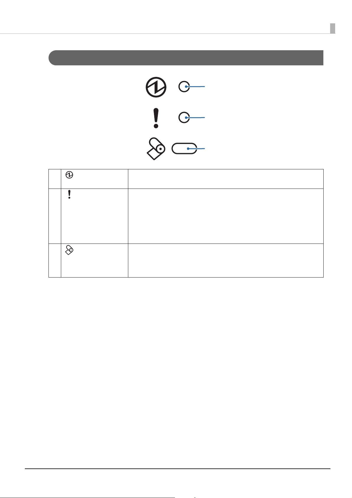
Key to Symbols
The symbols in this manual are identified by their level of importance, as defined below. Read the following
carefully before handling the product.
You must follow warnings carefully to avoid serious bodily injury.
WARNING
Provides information that must be observed to prevent damage to the equipment or loss of data.
• Possibility of sustaining physical injuries.
CAUTION
• Possibility of causing physical damage.
• Possibility of causing information loss.
Provides information that must be observed to avoid damage to your equipment or a malfunction.
Provides important information and useful tips.
Warnings
WARNING
• To avoid risk of electric shock, do not set up this product or handle cables during a
thunderstorm
• Never insert or disconnect the power plug with wet hands.
Doing so may result in severe shock.
• Handle the power cable with care.
Improper handling may lead to fire or electric shock.
∗ Do not modify or attempt to repair the cable.
∗ Do not place any heavy object on top of the cable.
∗ Avoid excessive bending, twisting, and pulling.
∗ Do not place the cable near heating equipment.
∗ Check that the plug is clean before plugging it in.
∗ Be sure to push the plug all the way in.
• Be sure to use the specified AC adapter.
Connection to an improper power source may cause fire or shock.
• Do not place multiple loads on the power outlet.
Overloading the outlet may lead to fire.
• Shut down your equipment immediately if it produces smoke, a strange odor, or unusual noise.
Continued use may lead to fire. Immediately unplug the equipment and contact qualified
service personnel.
• Never attempt to repair this product yourself. Improper repair work can be dangerous.
• Never disassemble or modify this product.
Tampering with this product may result in injury or fire.
• Do not allow foreign matter to fall into the equipment.
Penetration by foreign objects may lead to fire.
3
Page 4
WARNING
Cautions
CAUTION
• If water or other liquid spills into this equipment, do not continue to use it.
Continued use may lead to fire. Unplug the power cord immediately and contact qualified
service personnel.
• Do not use aerosol sprayers containing flammable gas inside or around this product.
Doing so may cause fire.
• Do not connect cables in ways other than those mentioned in this manual.
Different connections may cause equipment damage or fire.
• Be sure to set this equipment on a firm, stable, horizontal surface.
The product may break or cause injury if it falls.
• Do not use this product in locations subject to high humidity or dust levels.
Excessive humidity and dust may cause equipment damage or fire.
• Do not place heavy objects on top of this product. Never stand or lean on this product.
Equipment may fall or collapse, causing breakage and possible injury.
• Take care not to push your hand or finger against the manual cutter. Doing so may injure your
hand or finger.
∗ When you remove printed paper
∗ When you perform other operations such as loading/replacing roll paper
• Do not open the roll paper cover without taking the necessary precautions, as this can result in
injury from the autocutter fixed blade.
• To ensure safety, unplug this product before leaving it unused for an extended period.
• Do not remove the user interface board installed on this product.
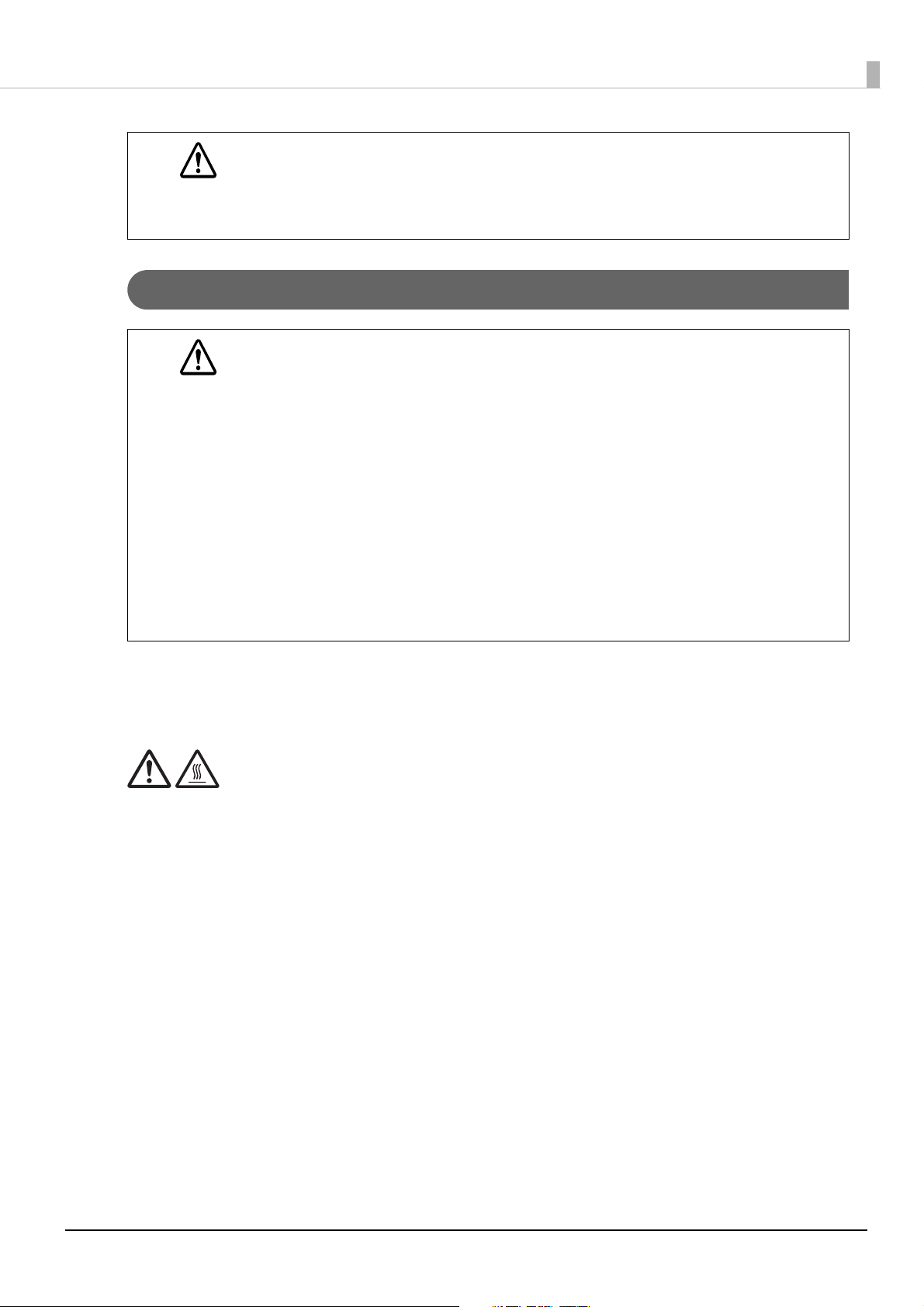
Caution Labels
The caution labels on the product indicate the following precautions.
CAUTION:
Do not touch the thermal head and the frame on its side during or immediately after use. After printing, the thermal head
and its surroundings can be very hot.
Restriction of Use
When this product is used for applications requiring high reliability/safety, such as transportation devices
related to aviation, rail, marine, automotive, etc.; disaster prevention devices; various safety devices, etc.; or
functional/precision devices, etc., you should use this product only after giving consideration to including failsafes and redundancies into your design to maintain safety and total system reliability.
Because this product was not intended for use in applications requiring extremely high reliability/safety, such as
aerospace equipment, main communication equipment, nuclear power control equipment, or medical
equipment related to direct medical care, etc., please make your own judgment on this product's suitability after
a full evaluation.
4
Page 5

Note About Interference
• This product generates, uses, and can radiate radio frequency energy and, if not installed and used in
accordance with the instruction manual, may cause harmful interference to radio communications.
• If this equipment does cause harmful interference to radio or television reception, which can be determined
by turning the equipment off and on, the user is encouraged to try to correct the interference by one or more
of the following measures:
- Reorient or relocate the receiving antenna for the radio/TV.
- Increase the separation between the equipment and the radio/TV.
- Connect the equipment into an outlet on a circuit different from that to which the receiver is connected.
- Consult your dealer or an experienced radio/TV technician for help.
• Never disassemble or modify this product.
• Seiko Epson Corporation shall not be liable for interference to radio/TV resulting from changes or
modifications to this product not expressly approved by Seiko Epson Corporation.
Open Source Software License
This product uses open source software in addition to Epson proprietary software. For information of the open
source software used in this product, see the following URL.
http://xxx.xxx.xxx.xxx/licenses.html
For “xxx.xxx.xxx.xxx” in the above URL, input your printer’s IP address.
5
Page 6

About this Manual
Aim of the Manual
This manual provides developers/engineers with all the necessary information for design, development and
installation of a POS system, and also design and development of a printer application.
Manual Content
The manual is made up of the following sections:
Chapter 1 Product Overview
Chapter 2 Setup
Chapter 3 Advanced Usage
Chapter 4 Application Development I
Chapter 5 Handling
Chapter 6 Replacement of the TM-T20II
Appendix
Product Specifications
Specifications of I
nterfaces and Connectors
nformation
6
Page 7

Contents
■ For Safety.................................................................................................................................3
Key to Symbols.................................................................................................................................................................. 3
Warnings ............................................................................................................................................................................. 3
Cautions............................................................................................................................................................................... 4
■ Caution Labels........................................................................................................................4
■ Restriction of Use...................................................................................................................4
■ Note About Interference ......................................................................................................5
Open Source Software License ................................................................................................................................... 5
■ About this Manual .................................................................................................................6
Aim of the Manual ........................................................................................................................................................... 6
Manual Content ................................................................................................................................................................ 6
■ Contents ..................................................................................................................................7
Product Overview ..........................................................................................11
■ Features ................................................................................................................................ 11
■ Product Configurations ..................................................................................................... 12
Models................................................................................................................................................................................12
Accessories .......................................................................................................................................................................12
■ Parts and Functions............................................................................................................ 13
LED lights ..........................................................................................................................................................................14
Connectors .......................................................................................................................................................................15
■ Status and Errors................................................................................................................. 16
Online and Offline..........................................................................................................................................................16
Automatically Recoverable Errors ............................................................................................................................16
Recoverable Errors .........................................................................................................................................................17
Unrecoverable Errors ....................................................................................................................................................17
Status Display ..................................................................................................................................................................18
■ NV Memory .......................................................................................................................... 19
NV Graphics Memory....................................................................................................................................................19
User NV Memory ............................................................................................................................................................19
Memory Switches (Customized Value)...................................................................................................................19
R/E (Receipt Enhancement) ........................................................................................................................................19
User-defined Page .........................................................................................................................................................20
Maintenance Counter...................................................................................................................................................20
■ Simple Setup for Wireless LAN ......................................................................................... 21
■ Useful Functions for Smart Devices ................................................................................ 22
QR Code.............................................................................................................................................................................22
7
Page 8

Setup ............................................................................................................... 23
■ Flow of Setup....................................................................................................................... 23
■ Installing the Printer ..........................................................................................................24
Installing the Printer Vertically ..................................................................................................................................24
Hanging the Printer on a Wall....................................................................................................................................25
■ Adjusting the Roll Paper Near-End Sensor .................................................................... 27
■ Connecting the AC adapter .............................................................................................. 28
Connecting Procedure .................................................................................................................................................28
■ Connecting the Printer to the Host ................................................................................. 29
USB Interface ...................................................................................................................................................................29
Serial Interface ................................................................................................................................................................29
Ethernet Interface ..........................................................................................................................................................30
Wireless LAN Interface (when OT-WL06 is used) ................................................................................................30
■ Connecting the Cash Drawer............................................................................................ 34
Cash Drawer Requirements ........................................................................................................................................34
Connecting the Drawer Kick Cable..........................................................................................................................35
■ Connecting the Optional External Buzzer ..................................................................... 36
Connecting Procedure .................................................................................................................................................36
■ Connecting the Optional Wireless LAN Unit.................................................................. 38
■ Attaching the Power Switch Cover.................................................................................. 39
■ Changing the Paper Width................................................................................................ 40
Advanced Usage ............................................................................................ 41
■ Software Settings ...............................................................................................................41
Feature ...............................................................................................................................................................................42
■ Setting/Checking Modes................................................................................................... 50
Self-test Mode .................................................................................................................................................................52
NV Graphics Information Print Mode......................................................................................................................52
Receipt Enhancement Information Print Mode ..................................................................................................53
Software Setting Mode ................................................................................................................................................53
Restore Default Values Mode.....................................................................................................................................55
Interface Setup Mode...................................................................................................................................................56
Peripheral Device Information Print Mode...........................................................................................................57
Hexadecimal Dumping Mode ...................................................................................................................................58
■ Printing a Status Sheet ...................................................................................................... 59
■ Resetting the Interface Settings ...................................................................................... 61
8
Page 9

Application Development Information....................................................... 62
■ Controlling the Printer....................................................................................................... 62
ePOS-Print XML...............................................................................................................................................................62
ESC/POS.............................................................................................................................................................................62
■ Controlling the Cash Drawer ............................................................................................ 63
■ Controlling the Optional External Buzzer...................................................................... 64
■ Software ............................................................................................................................... 65
Development Kits ..........................................................................................................................................................65
Drivers ................................................................................................................................................................................66
Utilities ...............................................................................................................................................................................67
Others.................................................................................................................................................................................67
Download .........................................................................................................................................................................67
Handling ......................................................................................................... 68
■ Installing and Replacing Roll Paper ................................................................................ 68
■ Removing Jammed Paper ................................................................................................. 70
When the Roll Paper Cover Cannot be Opened..................................................................................................70
■ Cleaning the Printer ........................................................................................................... 72
Cleaning the Printer Case............................................................................................................................................72
Cleaning the Thermal Head/Platen Roller .............................................................................................................72
■ Preparing for Transport ..................................................................................................... 73
Replacement of the TM-T20II........................................................................ 74
■ Compatibility....................................................................................................................... 74
Printing ..............................................................................................................................................................................74
Print Speed .......................................................................................................................................................................74
Logo Registration...........................................................................................................................................................74
Driver Compatibility......................................................................................................................................................74
Overall Dimensions .......................................................................................................................................................75
Appendix......................................................................................................... 76
■ Product Specifications....................................................................................................... 76
Printing Specifications .................................................................................................................................................77
Character Specifications ..............................................................................................................................................78
Paper Specifications ......................................................................................................................................................79
Printable Area..................................................................................................................................................................80
Printing and Cutting Positions ..................................................................................................................................82
Electrical Characteristics..............................................................................................................................................83
9
Page 10

Environmental Conditions..........................................................................................................................................84
External Dimensions and Mass .................................................................................................................................85
■ Specifications of Interfaces and Connectors................................................................. 86
USB Interface ...................................................................................................................................................................86
RS-232 Serial Interface .................................................................................................................................................87
Ethernet Interface ..........................................................................................................................................................90
Wireless LAN Interface (when OT-WL06 is used) ................................................................................................92
10
Page 11

Chapter 1 Product Overview
Product Overview
This chapter describes features of the product.
Features
Printing
• High speed receipt printing is possible (250 mm/s {9.84"/s} maximum).
• Switching from 80 mm {3.15"} width paper printing to 58 mm {2.28"} width paper printing is available.
Handling
Easy drop-in paper loading
Software
• Command protocol is based on the ESC/POS® Proprietary Command System.
• Windows printer drivers, OPOS ADK, and OPOS ADK for .NET are available.
• Printing of various types of bar codes, GS1-DataBar, and two-dimensional symbols (PDF417, QR code,
MaxiCode, Composite Symbology, Aztec Code, DataMatrix) is supported.
• A maintenance counter function is supported.
• Multiple languages are supported for code pages, Windows drivers, and utility software.
Interface
The interface is selectable when purchasing the product.
Environment
Paper reduction function is available.
Others
• Various installation layouts (horizontal, vertical, and wall-hanging installation) are selectable.
• Optional Wireless LAN unit and external buzzer are available.
11
Page 12

Product Configurations
Models
• Serial (RS-232C)/USB interface model
• Ethernet interface model
Accessories
Included
• Roll paper (for operation check)
• Power switch cover
• Soft power switch cover
Chapter 1 Product Overview
• Wall hanging bracket
• Rubber feet for vertical installation
• 58 mm width roll paper guide
• AC adapter
• Interface cable*
• AC cable*
• User's Guide
*: Not included with some models
Options
• Affixing tape for fixing the printer (Model: DF-10)
• External buzzer (Model: OT-BZ20)
• Wireless LAN cable set (Model: OT-WL06)
12
Page 13
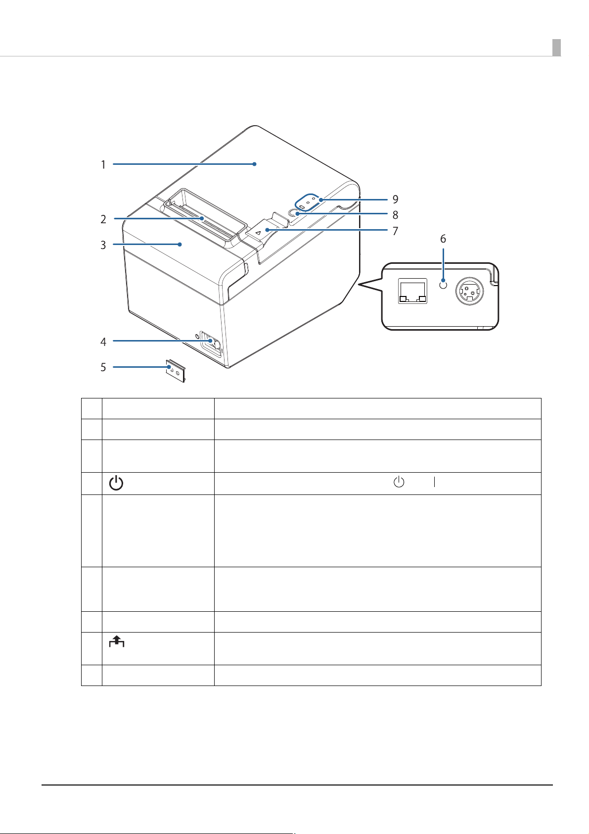
Parts and Functions
Chapter 1 Product Overview
1 Roll paper cover Open this cover to install/replace the roll paper.
2 Manual cutter Use this cutter when you cut the roll paper manually.
3 Cutter cover If the roll paper cover will not open due to a paper jam, open this cover and unlock the
autocutter blade.
4 Power switch Press this button to turn the printer on or off. ( : OFF/ : ON)
5 Power switch cover Put this cover on the power switch to prevent it being operated inadvertently.
To operate the power switch, insert an object with a pointed tip such as a ballpoint
pen into the hole on the power switch cover.
For attaching the power switch cover, see "Attaching the Power Switch Cover" on
page 39.
6
Status sheet button
(Ethernet interface model
only)
7 Cover open lever Use this button to open the roll paper cover.
8 Feed button Press this button to feed the roll paper by one line. Hold down this button to feed the
9 LED lights For details on the LED lights, see "LED lights" on page 14.
Press this button to print the interface status sheet, or to reset the interface settings.
roll paper continuously.
13
Page 14
LED lights
1
2
3
1 Power LED • On when the power supply is on.
• Off when the power supply is off.
Chapter 1 Product Overview
2
3
Error LED Lights or flashes when the printer is offline. (For information about the lighting and
flashing patterns, see "Status and Errors" on page 16.)
• Ligh
ts after the power is turned on or after a reset (offline). Automatically goes out
after a while to indicate that the printer is ready.
• Lights when the end of the roll paper is detected, and when printing has stopped
(offline). If this happens, replace the roll paper.
• Off when the printer is in standard mode (online).
Paper LED • Lights when there is no more roll paper. If the near-end detection is set to
“Enabled”, this LED also lights when the near-end of the paper is detected.
• Off when there is a sufficient amount of roll paper remaining.
• Flashes when a self-test is in progress or when macro execution standby state.
14
Page 15
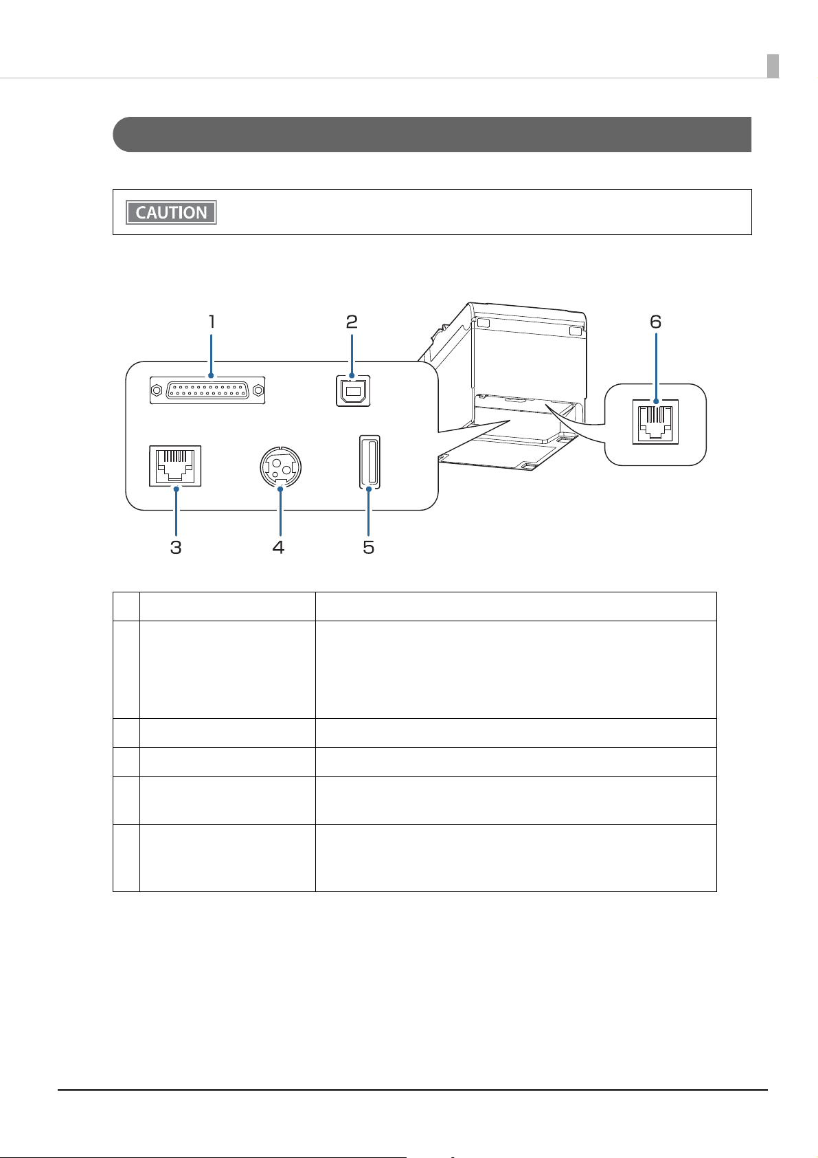
Connectors
All connectors are located on the lower rear of the printer.
• The interface installed differs according to the model.
• Do not remove the user interface board installed on this product.
Chapter 1 Product Overview
1 Serial interface Connects the serial cable for connecting to a computer.
2 USB (Type-B) connector Connects the USB cable for connecting to a computer.
The connector is covered with a plate when shipped with some model.
When using this connector with such model, set Interface Selection in the
printer's Software Setting Mode to [Built-in USB]. See "Software Settings"
on
page 41.
3
Ethernet connector Connects the 10BASE-T/100BASE-TX Ethernet cable.
4 Power supply connector Connects the AC cable. "Connecting the AC adapter" on page 28
5 USB (Type-A) connector Use only for connecting optional Wireless LAN unit.
L
eave the cover in place if this connector is not used.
6 Drawer kick connector Connects the cash drawer or the optional external buzzer.
"Connecting the Cash Drawer" on page 34
"Connec
ting the Optional External Buzzer" on page 36
15
Page 16

Status and Errors
The LEDs light or flash to indicate the printer status.
The printer cannot print while an error is left unsolved.
Online and Offline
Online
The printer is online and ready for normal printing unless there is a reason to go offline.
Offline
The printer automatically goes offline under the following conditions:
Chapter 1 Product Overview
• While the printer power is turning on/off
• While a self-test is running
• While roll paper is fed using the Feed button
• When the printer stops printing due to a paper end
(When the paper end is detected by the roll paper end sensor)
• During an operation standby state
• When an error has occurred ("Status and Errors" on page 16)
hile the roll paper cover is open
• W
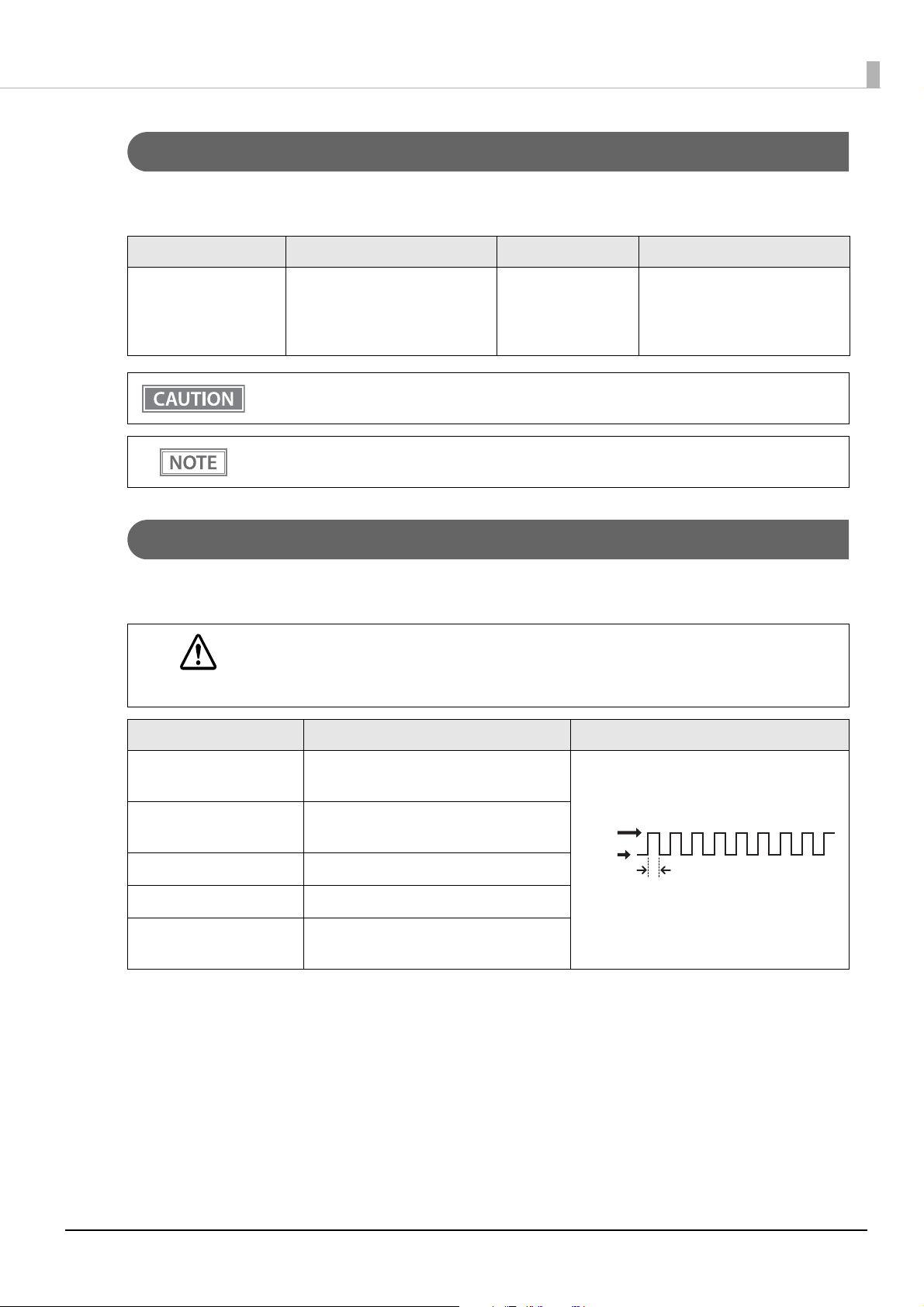
Automatically Recoverable Errors
The printer cannot print when automatically recoverable errors occur. When the conditions for recovery
described below are met, the printer automatically recovers from the error.
Error Error description Error LED status Condition for Recovery
Roll paper cover
open error
Head temperature error A high temperature outside the
The roll paper cover was opened
during printing
thermal head drive operating
range was detected
ON The roll paper cover is closed
ON When the thermal head cools
16
Page 17
Chapter 1 Product Overview
LED OFF
LED ON
Approx. 320 ms
Recoverable Errors
The printer cannot print when a recoverable error occurs. When the roll paper cover is closed, the power is
turned off and on again, or an error recovery command is received, the printer can recover from the error.
Error Error description Error LED status Condition for Recovery
Autocutter error Autocutter does not work
correctly
The error recovery command is valid only if a recoverable error (excluding automatically
recoverable errors) occurs.
Use the TM-T20III Utility to change the condition for recovery. For details, see the TM-T20III Utility
User's Manual.
ON Recovers from the error when
the jammed paper or foreign
matter is removed, and the roll
paper cover is closed
Unrecoverable Errors
The printer cannot print when an unrecoverable error occurs. If the error persists after turning the printer off
and then on again, the printer may be defective. Contact qualified service personnel.
Turn off the power immediately when an unrecoverable error occurs.
CAUTION
Error Error description Error LED flash code
R/W error in memory After R/W checking, the printer does not
work correctly.
High voltage error The power supply voltage is extremely
high.
Low voltage error The power supply voltage is extremely low.
CPU execution error The CPU is executing an incorrect address.
Internal circuit connection
error
Internal circuits are not connected
correctly.
17
Page 18
Chapter 1 Product Overview
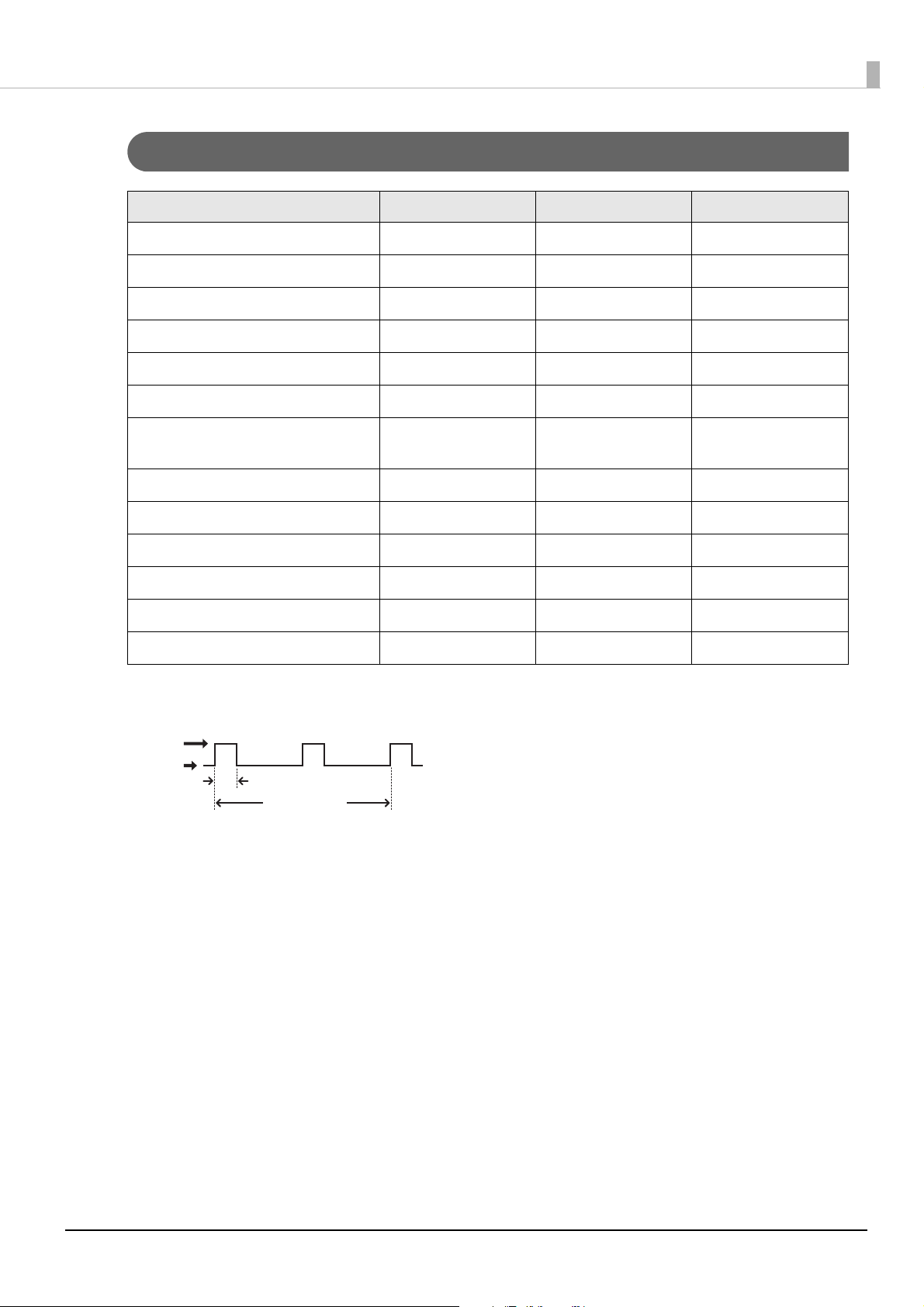
Status Display
Power LED Error LED Paper LED
Online ON OFF OFF
Initializing after power-on ON ON -
Running a self-test ON OFF -
Waiting to continue self-test ON OFF Flashing
Feeding using the Feed button ON OFF -
Waiting to execute a macro ON OFF Flashing
Roll paper cover open while the printer
is not printing
No paper ON ON ON
While updating firmware ON Flashing Flashing
While in forced firmware update mode
While in power off standby ON OFF Flashing
The network link is down ON Flashing
Waiting to print status sheet ON ON Flashing
ON ON -
ON ON ON
* -
-: Changes depending on whether or not paper is detected.
*: The error LED flashing patterns are as follows.
LED ON
LED OFF
Approx. 640 ms
Approx. 5,120 ms
18
Page 19
Chapter 1 Product Overview
NV Memory
The printer is equipped with the NV memory (Nonvolatile Memory) to store data even after the printer power
is turned off. NV memory contains the following memory areas for the user:
• NV graphics memory
• User NV memory
• Memory switches (Customized value)
• R/E (Receipt Enhancement)
• User-defined page
• Maintenance counter
As a guide, NV memory rewriting should be 10 times or less a day when you program applications.
CAUTION
NV Graphics Memory
Graphics, such as shop logos to be printed on receipts, can be stored. Even with a serial interface model whose
transmission speed is low, high speed graphics printing is possible.
Use the TM-T20III Utility to register graphics.
You can confirm the registered graphics in the NV graphics information print mode.
• For detailed information about the Epson TM-T20III Utility, see the TM-T20III Utility User's
Manual.
• For information about how to use the NV graphics information print mode, see "NV Graphics
I
nformation Print Mode" on page 52.
User NV Memory
You can store and read text data for multiple purposes, such as for storing a note including customizing or
maintenance information of the printer.
Memory Switches (Customized Value)
You can configure various settings of the printer.
For more information, see "Software Settings" on page 41.
R/E (Receipt Enhancement)
Graphics, such as shop logos to be printed on top or bottom of receipts can be registered.
Use the TM-T20III Utility to register graphics.
19
Page 20

Chapter 1 Product Overview
User-defined Page
You can store character data in the user-defined page (character code table: page 255) so that you can also print
characters not resident in the printer.
Maintenance Counter
With this function, printer information, such as the number of lines printed, the number of autocuts, and
printer operation time after the printer starts working, is automatically stored in NV memory. You can use the
counter information for periodical checks or part replacement.
You can also check the print head running length and number of times of autocutting with the selftest (see "Self-test Mode" on page 52).
20
Page 21
Chapter 1 Product Overview
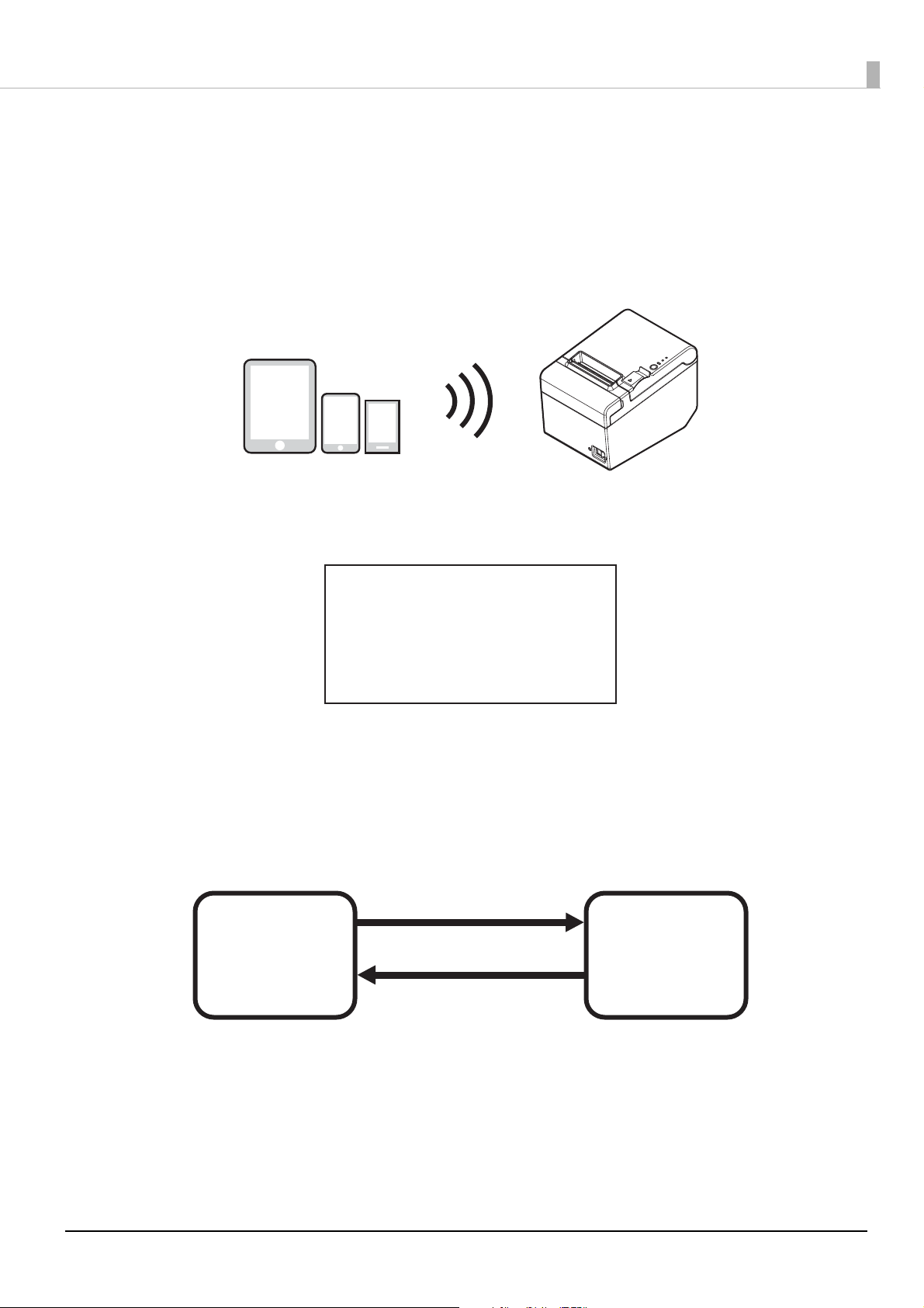
Simple Setup for Wireless LAN
This printer comes with a mode (SimpleAP) that allows printers to connect with a smart device or a computer
without requiring a wireless access point. This allows you to easily setup a wireless LAN for the printer by using
a printer settings tool (TM-T20III Utility, Epson TM Utility for iOS/Android, or EpsonNet Config) even
without a network environment such as access points.
SimpleAP mode is enabled by default when shipping from the factory. When SimpleAP mode is enabled and
the printer is turned on, the following information is printed automatically.
SimpleAP Start
SSID
Encryption Type
Passphrase
IP Address
MAC Address
: EPSON_Printer
: WPA2-PSK
: 12345678
: 192.168.192.168
: xx-xx-xx-xx-xx-xx
Although operations are performed in SimpleAP mode during the initial startup, operations switch to standard
mode (infrastructure mode) when changing settings in Epson TM-T20III Utility or EpsonNet Config. After
switching, operations continue in standard mode. If you want to make settings in SimpleAP mode again,
initialize the communication settings. ("Resetting the Interface Settings" on page 61)
Changing to standard mode
Ex.) Change IP address,
change SSID
SimpleAP mode
(default setting)
Standard mode
(infrastructure
mode)
Initialize the communication
settings
21
Page 22

Chapter 1 Product Overview
Useful Functions for Smart Devices
You can easily connect this product to the network by using the QR code printed on the status sheet.
QR Code
Capture the QR code printed on the status sheet with the camera on your smart device to acquire the printer
information (information for specifying the device).
Specify the target printer using the acquired information to connect to the network.
• To use the function, programming using Epson ePOS SDK is required. In addition to the QR code
capturing operations, use Printer Easy Select API to achieve this function.
See the “Epson ePOS SDK for Android/iOS User's Manual” and the Epson ePOS SDK sample
program for more details. The sample program also contains a sample implementation method
for capturing a QR code.
• You can try a demo of the function by using Epson TM Utility for iOS/Android.
22
Page 23
Setup
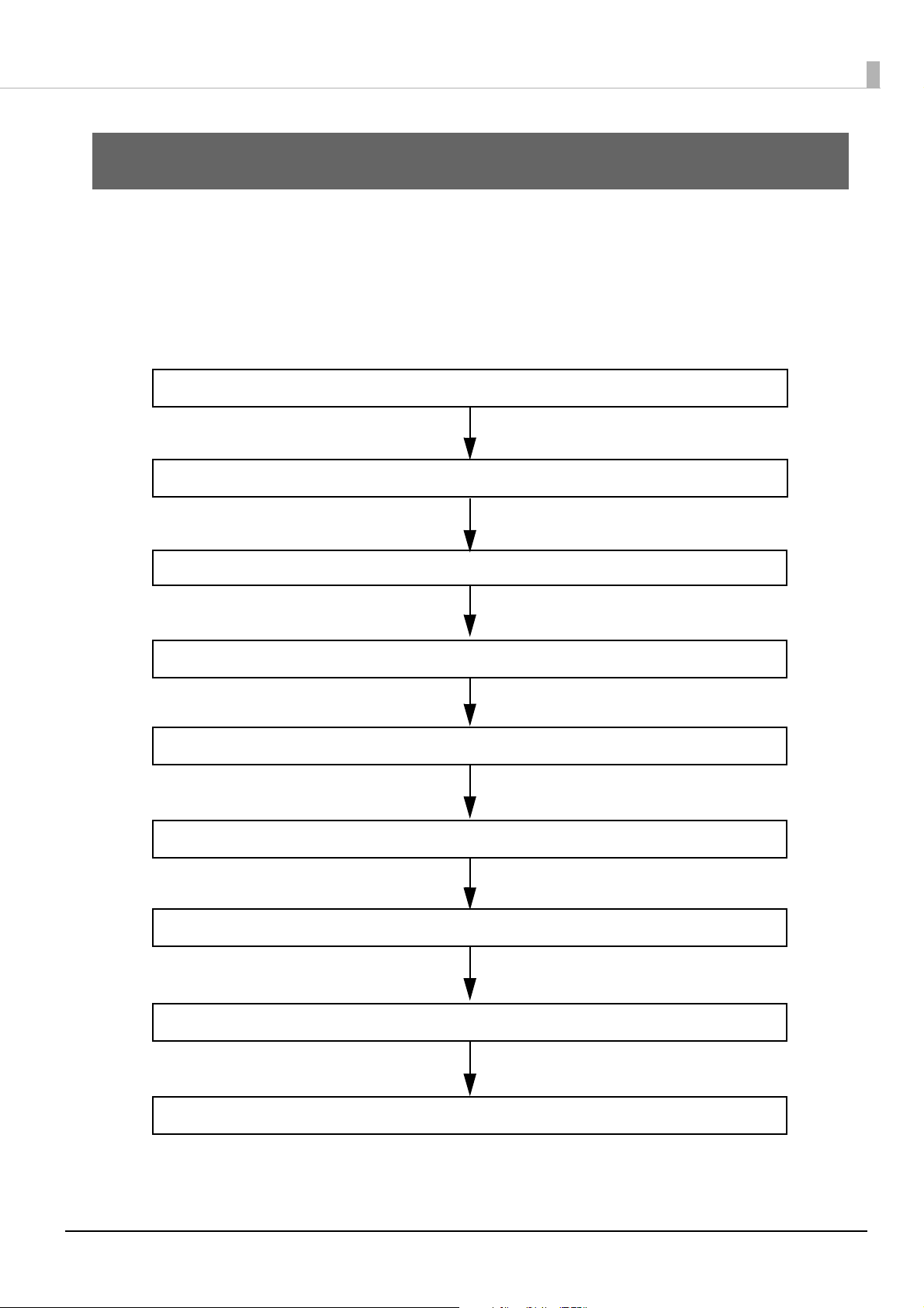
2. Adjusting the Roll Paper Near-End Sensor (page 27)
5. Connecting the Cash Drawer (page 34)
3. Connecting the AC adapter (page 28)
1. Installing the Printer (page 24)
4. Connecting the Printer to the Host (page 29)
6. Connecting the Optional External Buzzer (page 36)
8. Attaching the Power Switch Cover (page 39)
9. Changing the Paper Width (page 40)
7. Connecting the Optional Wireless LAN Unit (page 38)
This chapter describes setup and installation of the product and peripherals.
Flow of Setup
This chapter consists of the following sections along with the setup flow of the product and peripherals.
Chapter 2 Setup
23
Page 24
Chapter 2 Setup
Horizontal installation
Vertical installation
Hanging on a wall
Rubber feet
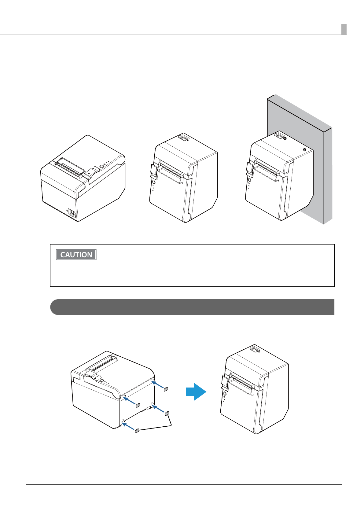
Installing the Printer
You can install the printer horizontally on a flat surface (with the paper exit on top) or vertically (with the paper
exit at the front). Also, you can hang it on a wall using the included accessories.
• Do not place the printer in a dusty location.
• Do not knock or strike the printer. This may cause defective print.
• Do not catch cables or place foreign matter under the printer.
• Take measures to prevent the printer from moving by vibration during paper cutting and when
using a drawer. Affixing tape (Model: DF-10) is provided as an option.
Installing the Printer Vertically
When installing the printer vertically, attach the four rubber feet in the rectangular indents in the printer case,
as shown in the illustration below.
24
Page 25
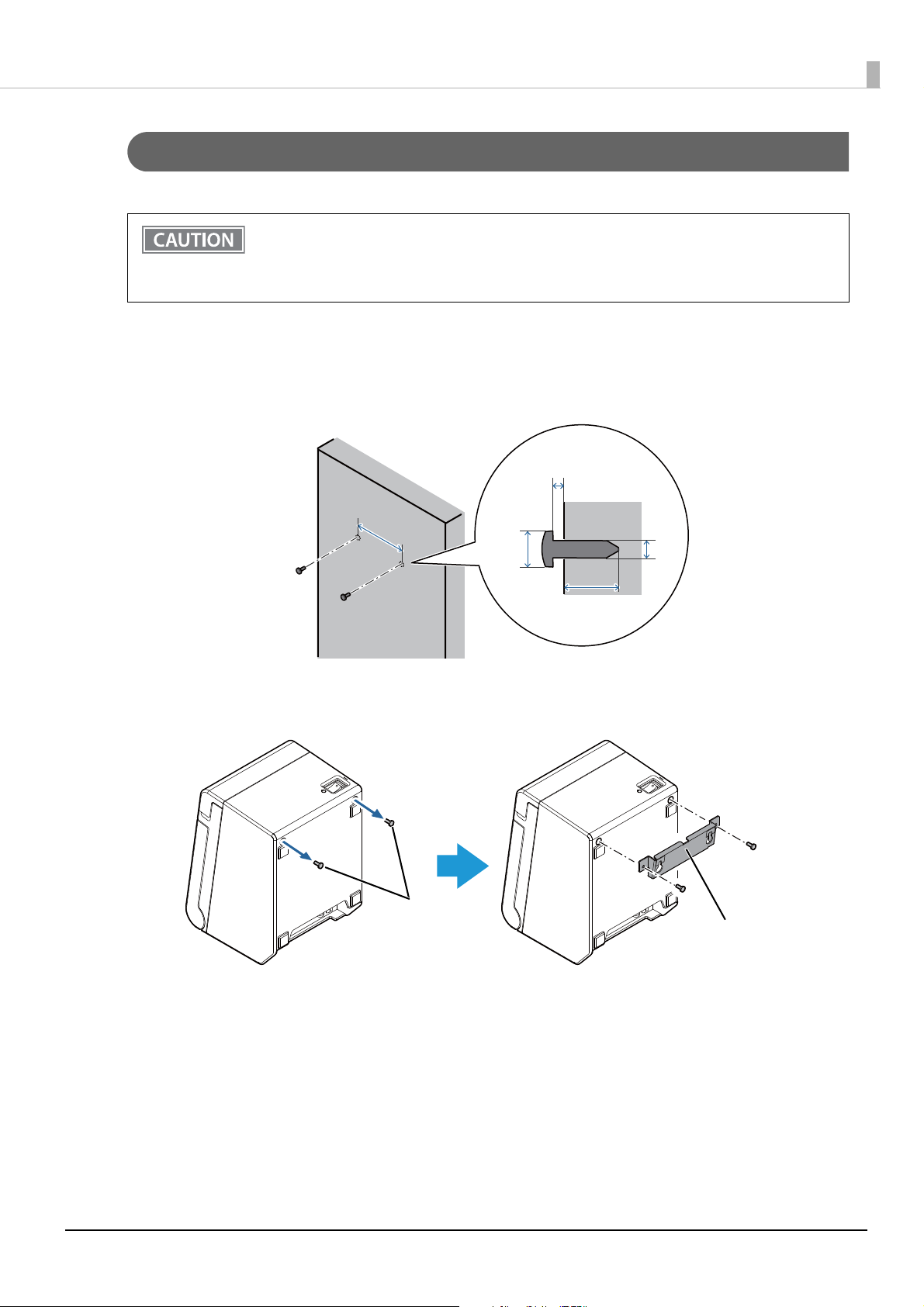
Hanging the Printer on a Wall
80 mm
{3.15"}
4 mm
{0.16"}
3 to 4 mm {0.12 to 0.16"}
7 to 9 mm
{0.28 to 0.35"}
10 mm {0.39"} or more
Screws
Wall hanging bracket
To securely hang the printer on a wall, follow the steps below.
• Hang the printer on a wood, concrete, or metal wall. The thickness of the wall should be 10 mm
{0.4"} or more.
• Be sure to use metallic screws.
• The screws to be put into the wall must have a pull-out strength of 150 N (15.3 kgf) or more.
Put two screws (diameter: 4 mm {0.16"}, head diameter: 7 to 9 mm {0.28 to 0.35"}) into
1
the wall at an interval of 80 mm {3.15"}.
Make sure the length of the screw in the wall is 10 mm {0.39"} or more, and the length outside the
wall is 3 to 4 mm {0.12 to 0.16"}.
Chapter 2 Setup
Remove the two screws from the printer, and then attach the wall hanging bracket to
2
the printer using the screws.
25
Page 26
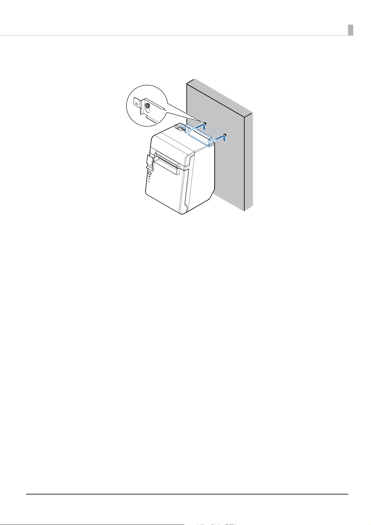
Align the holes in the wall hanging bracket with the screws on the wall, and hook it
3
securely.
Chapter 2 Setup
26
Page 27
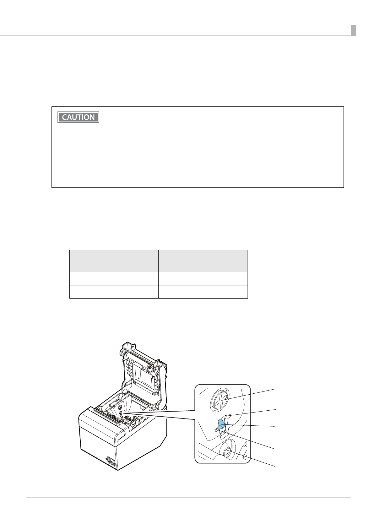
Adjusting the Roll Paper Near-End Sensor
Adjustment screw
Positioning plate
Detection lever
Upper position
Lower position
Below are two situations where a roll paper near-end sensor adjustment is required.
• To adjust the detection position to suit the diameter of the roll paper core used.
• To adjust the detection position of remaining amount of paper.
• The roll paper near-end detection function can be used only when this product is installed
horizontally.
• Be sure to disable the near-end detection when the product is installed vertically or is wallmounted. Failure to do so may lead to erroneous detection.
• Since roll paper cores vary slightly in shape, depending on paper roll design and manufacturing
tolerances, it is impossible to detect the remaining paper exactly.
• Use roll paper with a core inner diameter of 12 mm {0.47"} and outer diameter of 18 mm {0.71"}
so that the near-end sensor can detect the remaining paper as accurately as possible.
• To use the near-end detection, it must be enabled using the memory switches. See "Software
Setting Mode" on page 53 for details about the making the memory switch settings.
Follow the steps below to adjust the roll paper near-end sensor.
Chapter 2 Setup
Open the roll paper cover, and remove the roll paper.
1
Loosen the adjustment screw fastening the sensor, and align the upper edge of the
2
positioning plate with the adjustment position.
Adjustment position
Upper Approx. 27 mm {1.06"}
Lower (Default setting) Approx. 23 mm {0.97"}
Tighten the adjustment screw.
3
After adjustment, make sure that the detection lever operates smoothly.
4
Remaining amount of paper
(outer diameter)
27
Page 28
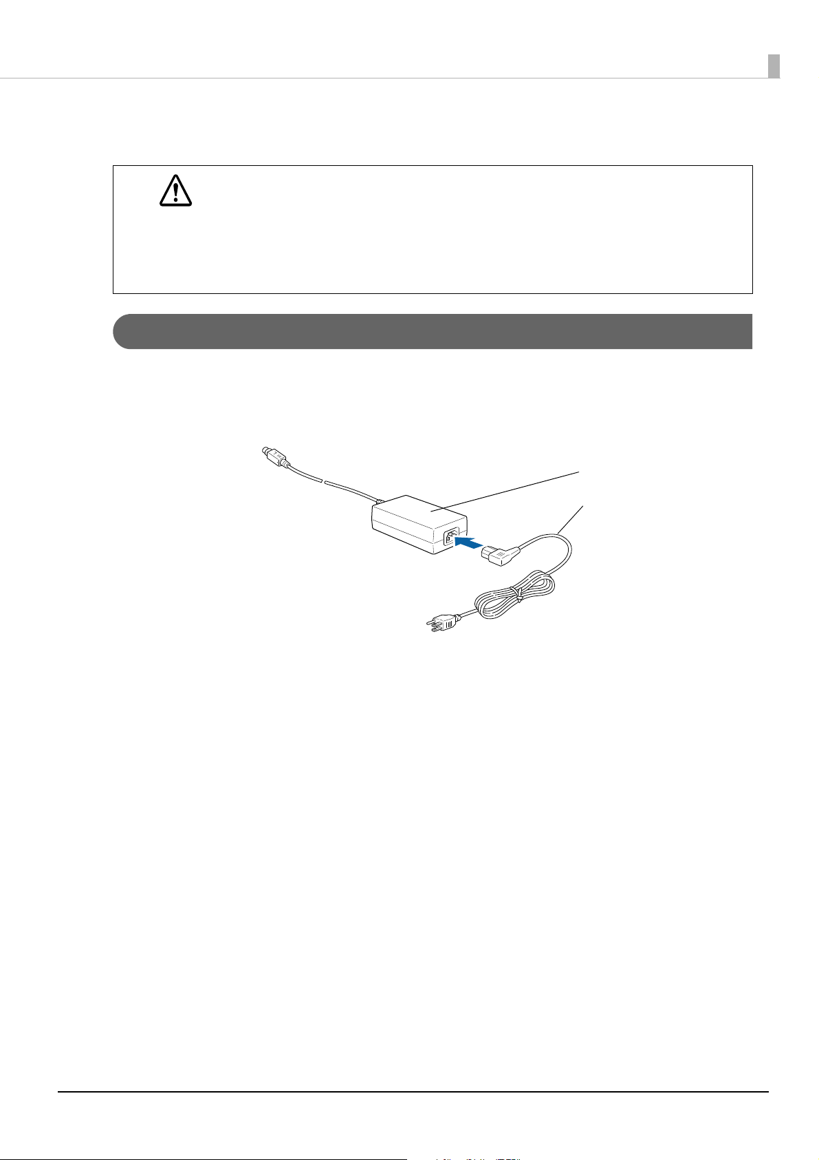
Connecting the AC adapter
AC adapter
AC cable
• Be sure to use the specified AC adapter [AC adapter, C1 (Model: M235B)]. Penetration by foreign
objects may lead to fire.
WARNING
Connecting Procedure
Make sure the printer is turned off.
1
Connect the AC cable to the AC adapter.
2
• Never insert the AC cable plug into a socket that does not meet the input voltage of the AC
adapter.
Doing so may result in damage to the printer.
• Should a fault ever occur, immediately turn off the power to the printer and unplug the AC cable
from the wall socket.
Chapter 2 Setup
Connect the DC cable of the AC adapter to the power supply connector (stamped
3
24V).
28
Page 29
Chapter 2 Setup
USB cable
Hooks
Connecting the Printer to the Host
• Be sure to install the driver before connecting the printer to the host computer.
• The printer uses a modular connector specifically designed for the cash drawer. Do not connect
the connector to an ordinary telephone line.
USB Interface
When using USB cable to connect with host device, connect the USB cable to the printer, and after starting the
host device, turn the printer on.
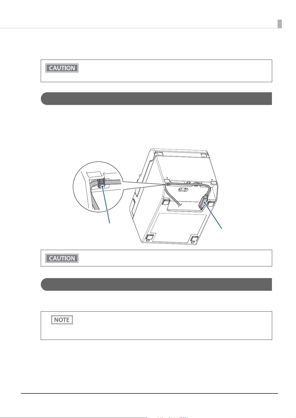
When connecting the USB cable to the printer, fix the cable with the hook to prevent it from being
disconnected.
Do not place any weight or stress on the cable when using. Doing so could damage the cable and
connectors.
Serial Interface
When connecting to the host computer through a serial interface (RS-232), connect a serial cable to the printer,
start the host computer, and then turn on the printer.
• When using connectors equipped with screws, tighten the screws on both sides to secure the
connectors firmly.
• When using interface cables equipped with a ground line, attach the ground line to the screw
hole marked “FG” on the printer.
29
Page 30
Chapter 2 Setup
Ethernet Interface
Use an Ethernet cable to connect the printer to network via a hub.
Use Epson TM-T20III Utility or EpsonNet Config to set network.
For detailed information about the Epson TM-T20III Utility, refer to the TM-T20III Utility User's Manual.
For details on EpsonNet Config, refer to EpsonNet Config User's Guide.
• When LAN cables are installed outdoors, make sure they are connected through devices that
have surge protection.
Otherwise, the devices can be damaged by lightning.
• Never attempt to connect the drawer kick cable or a standard telephone line cable to the LAN
connector.
As same with Conventional models, you can use EpsonNet Config (Web version) in the same way.
User name/password: epson
Wireless LAN Interface (when OT-WL06 is used)
You can connect using a wired cable (LAN/USB), or connect using SimpleAP mode, and setup a wireless LAN
using a network configuration tool. When setting up multiple printers, you can connect using a wired cable
(LAN/USB) and setup a wireless LAN using the Epson Deployment Tool.
Using Epson TM Utility for iOS/Android, you can easily connect the printer to the network from an iOS or
Android devices.
• When using wireless LAN, make sure you disconnect the LAN cable. If a LAN cable is connected,
wireless LAN is disabled.
• When you set up the access point at the same time, set the access point in advance and check
that it operates correctly.
• Examine the radio wave situation in the surrounding area before use.
• Avoid using the same channel that is used in the neighboring shops where Wireless LAN is used.
• When using the printer in environments where kitchen microwaves and other devices that may
interfere radio waves are installed, observe the following points.
∗ Keep the printer away from the devices, such as kitchen microwaves, that may cause radio wave
interference.
∗ Use channels that are away from the frequency bands that may cause radio wave interference.
∗ Place shields between the printer and the devices that may cause radio wave interference.
∗ Select either 2.4 GHz or 5 GHz, whichever is free from radio wave interference.
∗ In auto channel setting for the access point, do not select a channel in which the devices may cause
radio wave interference.
• In the infrastructure mode, W53 and W56 channels are not available to connect to a stealth SSID
access point.
For SimpleAP mode, see "Simple Setup for Wireless LAN" on page 21.
30
Page 31

Setting up Using a SimpleAP Connection from a Windows Computer
Necessary Items
Prepare the following items.
• Computer for setting: Windows 10/8/7
Computer equipped with a wireless LAN function
• Utility for setting: TM-T20III Utility or EpsonNet Config
Follow the steps below to connect the printer.
Turn on the printer.
1
After starting the printer, check that the “SimpleAP Start” is printed. If it is not printed, you need to
enable SimpleAP mode in interface setup mode.
Activate Windows Wireless Network Connection and select [EPSON_Printer] as the
2
connection device on the screen that appears.
If the window to enter a pass phrase appears, enter "12345678”.
Default settings on printer are the following values.
Chapter 2 Setup
Network mode SimpleAP mode
SSID EPSON_Printer
Passphrase 12345678
IP Address 192.168.192.168
When connecting to the printer is complete, setup the Wireless LAN using the TM-
3
T20III Utility or EpsonNet Config.
For information about the TM-T20III Utility, see the TM-T20III Utility User's Manual.
For details about EpsonNet Config, refer to EpsonNet Config User's Guide.
When setting the wireless LAN is complete, remove the wired cable (LAN/USB) and
4
restart the printer.
31
Page 32

Setting up Using a USB Connection from a Windows Computer
Necessary Items
• Computer for setting: Windows 10/8/7
• Utility for setting: TM-T20III Utility
• USB cable
Follow the steps below to connect the printer.
Connect the printer to the computer via the USB cable.
1
Turn on the computer.
2
Turn on the printer.
3
Start the TM-T20III Utility.
4
Chapter 2 Setup
Select the printer, and then press the [OK] button.
5
If the printer is not displayed, press the “Add Port” button, and then add the printer connected by
USB.
Perform network I/F as well as TCP/IP settings.
6
For details, see the TM-T20III Utility User's Manual.
When you have finished making settings, disconnect the USB cable, turn off the
7
printer, and then turn it back on.
To start wireless LAN communication, be sure to disconnect the USB cable, turn off the
printer, and then turn it back on.
32
Page 33

Setting up from a Smart Device
Necessary Items
Prepare the following items.
• Device for setting: iOS or Android device
• Utility for setting: Epson TM Utility for iOS/Android
Running Epson TM Utility for iOS/Android
Run the Epson TM Utility for iOS/Android.
1
Chapter 2 Setup
Set from “Wi-Fi Setup Wizard” in the menu.
2
Setup and Operation Workflow
1. Select the network you want to connect to.
2. Enter the passkey.
3. Perform a test print.
33
Page 34

Chapter 2 Setup
With shielded
Drawer kick connector
Printer side User side [Drawer kick side]
Drawer open/ close
switch
Drawer kick
solenoid
1
2
3
4
5
6
Connecting the Cash Drawer
• The optional external buzzer and the cash drawer cannot be used simultaneously. Do not
connect both the optional external buzzer and the cash drawer to the printer at the same time
by using a branched connector.
• The cash drawer cannot be used If the enable/disable setting for the optional external buzzer is
set to “enable”. When using the cash drawer, be sure to set it to “disable” using the Epson TMT20III Utility.
• Two driver transistors cannot be energized simultaneously.
• Leave intervals longer than 4 times the drawer driving pulse when sending it continuously.
Cash Drawer Requirements
Specifications of drawers differ depending on makers or models. When you use a drawer other than specified,
make sure its specification meets the following conditions.
Otherwise, devices may be damaged.
• The load, such as a drawer kick solenoid, must be connected between pins 4 and 2 or pins 4 and 5 of the
drawer kick connector.
• When the drawer open/close signal is used, a switch must be provided between drawer kick connector pins 3
and 6.
• The resistance of the load, such as a drawer kick solenoid, must be 24 ohms or more or the input current
must be 1A or less.
• Be sure to use the 24V power output on drawer kick connector pin 4 for driving the equipment.
Drawer Connection Diagram
6 5 4 3 2 1
34
Page 35

Chapter 2 Setup
Connecting the Drawer Kick Cable
• Use a shield cable for the drawer kick cable.
• When using cash drawer, make sure to use the power supply for printer (connector pins 4).
WARNING
Connect the drawer kick cable to the drawer kick connector by pressing firmly until the connector clicks into
place.
• Do not insert a telephone line into the drawer kick connector.
Doing so may damage the telephone line or printer.
35
Page 36

Chapter 2 Setup
Volume adjustment k nob
Horizontal installation
(Front View)
Vertical/Wall-hanging installation
(Front View)
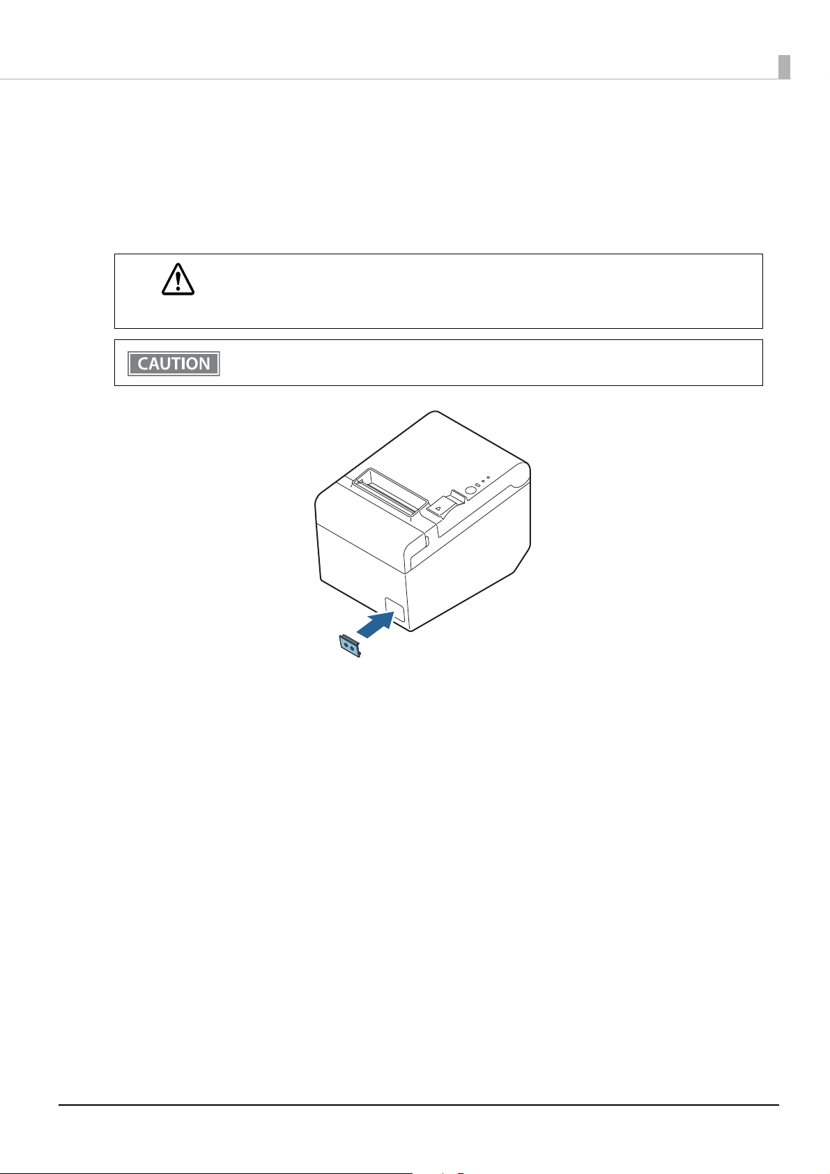
Connecting the Optional External Buzzer
When the optional external buzzer (model: OT-BZ20) is connected to the drawer kick connector of the printer,
you can set the printer so that it beeps when you send commands, when an error occurs, when executed auto
cutting, and when detected paper end. Settings for sound patterns and frequency depending on the occasions
the buzzer beeps are also available.
Use the TM-T20III Utility to make the buzzer settings: enable/disable setting, sound pattern setting, and
frequency setting.
• Be sure to turn off the printer before you connect/disconnect the optional external buzzer.
• The optional external buzzer and the cash drawer cannot be used simultaneously. Do not
connect both the optional external buzzer and the cash drawer to the printer at the same time
by using a branched connector.
Connecting Procedure
The optional external buzzer is recommended to be installed in the following positions.
• When using the printer horizontally: either side
• When using the printer vertically or on a wall: either side/top/bottom (only for wall hanging installation)
• Do not install the optional external buzzer at the roll paper exit.
• To prevent liquid from entering inside, it is recommended to install the optional external buzzer
so that the volume adjustment knob is positioned sideways or downward.
36
Page 37

Turn off the printer.
Affixing tape
Drawer kick
connector
Printer case
1
Clean and dry the printer case where the buzzer will be installed.
2
With 2 included pieces of the affixing tape combined, peel off the backing paper on
3
one side, and stick the tape in the center of the attaching surface of the buzzer unit.
Chapter 2 Setup
Connect the cable of the buzzer to the drawer kick connector on the printer.
4
Peel off the backing paper on the other side of the affixing tape, and attach the
5
buzzer unit to the printer case.
37
Page 38

Chapter 2 Setup
Connecting the Optional Wireless LAN Unit
The optional Wireless LAN cable set (OT-WL06) enables you to use the product with a Wi-Fi connection. For
more information, refer to User’s Manual of the Wireless LAN cable set.
• Be sure to turn off the printer when connecting the Wireless LAN unit.
• Depending on the installation conditions of the printer and the routing for cables connected to
it, the status of the radio waves for the Wireless LAN unit may decline. If this does happen, use an
extension cable.
38
Page 39
Chapter 2 Setup
Power switch cover
Attaching the Power Switch Cover
By attaching the power switch cover supplied, you can prevent accidental operations of the power switch. You
can press the power switch by inserting a sharp-pointed object in the holes on the power switch cover.
To detach the cover, use a sharp-pointed object.
A soft cover for the power switch is also included.
If an accident occurs with the power switch cover attached, unplug the AC cable immediately.
Continued use of the printer may cause fire or shock.
WARNING
Use the soft power switch cover if the printer is installed in a humid location or exposed to water. If
current leakage occurs, it could result in electric shock.
39
Page 40

Changing the Paper Width
Rectangular holes
Roll paper guide
You can change the paper width from 80 to 58 mm {3.15 to 2.28"} by installing the included 58-mm {2.28"}
width roll paper guide. Follow the steps below to change the paper width.
Because some parts of the print head and the autocutter contact the platen and they may become
worn out, once you change the paper width from 80 to 58 mm {3.15 to 2.28"} and use the printer,
you cannot change it back to 80 mm {3.15"}.
Open the roll paper cover.
1
Align the three tabs of the 58-mm {2.28"} width roll paper guide with the rectangular
2
holes in the printer, and push the guide downward.
Chapter 2 Setup
Using the memory switch, change the paper width setting.
3
For more information, see "Software Settings" on page 41.
40
Page 41

Chapter 3 Advanced Usage
Advanced Usage
Software Settings
With the memory switches and customized values, which are software settings for this printer, you can set the
various functions. For an outline of the functions, see the following pages. Use the Epson TM-T20III Utility or
Software Setting Mode to set the memory switches.
• For detailed information about the Epson TM-T20III Utility, refer to the TM-T20III Utility User's
Manual.
• For information about how to use the memory switch setting mode, see "Software Setting
M
ode" on page 53.
Item/Method Software Setting Mode Epson TM-T20III Utility
Automatic line feed ✔ ✔
USB power-saving function ✔ ✔
Paper sensors to output paper end signal ✔ ✔
Error signal output ✔ ✔
Data processing with reception error ✔ ✔
Recovery conditions from receive buffer BUSY ✔ ✔
Memory Switches
Receive buffer capacity ✔ ✔
Condition for BUSY ✔ ✔
Near-end detection ✔ ✔
Print density ✔ ✔
Print speed ✔ ✔
Power supply unit capacity ✔ ✔
Paper Width & Print Column ✔ ✔
Automatic paper reduction ✔ ✔
Character code table defaults ✔ ✔
International character defaults ✔ ✔
Font A auto replacement ✔
Font B auto replacement ✔
Customized Values
Autocutting after closing the roll paper cover ✔ ✔
Buzzer function ✔ ✔
Shrinking/Expanding graphics data ✔
USB class ✔ ✔
Serial Interface Communication Condition ✔ ✔
Interface selection ✔ ✔
41
Page 42

Chapter 3 Advanced Usage
Item/Method Software Setting Mode Epson TM-T20III Utility
Cut error release method ✔
Auto top logo printing ✔
Auto bottom logo printing ✔
Extended settings for auto top logo/bottom logo printing ✔
Feature
Automatic line feed
• Always disabled (default setting)
• Always enabled
When set to “Always enabled”, paper is fed by one line after data in the print buffer is printed.
USB power-saving function
• Disabled
• Enabled (default setting)
The USB power-saving function is valid only when the USB interface communication condition is
set to the vendor-defined class and the system configuration is set so that the USB driver can
support the USB power-saving function.
Paper sensors to output paper end signal
• Enables both the roll paper end sensor and the roll paper near-end sensor (default setting)
• Disables both of the sensors
Error signal output
• Enabled (default setting)
• Disabled
This model does not support this setting.
Data processing with reception error
• Prints “?” (default setting)
• Ignored
42
Page 43

Chapter 3 Advanced Usage
Recovery conditions from receive buffer BUSY
• Releases the BUSY state when the remaining receive buffer capacity reaches 256 bytes (default setting)
• Releases the BUSY state when the remaining capacity of the receive buffer reaches 138 bytes.
Receive buffer capacity
• 4 KB (default setting)
• 45 bytes
Condition for BUSY
• Receive buffer full/Offline (default setting)
• Receive buffer full
• In either case above, the printer enters the BUSY state after power is turned on, and when a self-
test is being run.
• If BUSY condition is set to “Receive buffer full,” the printer will not become BUSY
∗ When the roll paper cover is open
∗ When paper is fed by the FEED button
∗ When printing has stopped for a paper out
∗ When macro execution ready state
∗ When error has occurred
Near-end detection
• Disabled (default setting)
• Enabled
Print density
Selectable from levels 1 to 7 (Light to Dark)
Default setting: Level 4
Depending on the paper type, it is recommended to set the print density as shown in the table below for the best
print quality.
Original Paper type Density
AF50KS-E
KT55FA
KT48FA
F5041(48)
F5041(55)
When the print density level is increased, print speed may be reduced.
Level 4
Level 5
43
Page 44

Print speed
Selectable from levels 1 to 13 (Slow ~ Fast)
Default setting: Level 13
Depending on print conditions, such as print duty, thermal head temperature, and data
transmission speed, print speed is automatically adjusted, which may cause white lines due to
intermittent print (the motor sometimes stops). To avoid this, keep the print speed constant by
setting it lower.
Power supply unit capacity
Selectable from levels 1 to 3
Default setting: Level 3
Paper Width & Print Column
• To change the paper width, you need to install the 58 mm width paper guide plate. (See
"Changing the Paper Width" on page 40.)
• B
ecause some parts of the print head and the autocutter contact the platen and they may
become worn out, once you change the paper width from 80 to 58 mm {3.15 to 2.28"} and use
the printer, you cannot change it back to 80 mm {3.15"}.
Chapter 3 Advanced Usage
• 80 mm {3.15"} width paper/48 characters (default setting)
• 80 mm {3.15"} width paper/42 characters
• 58 mm {2.28"} width paper/35 characters
• 58 mm {2.28"} width paper/42 characters
Automatic paper reduction
• Disabled (default setting)
• Recommended setting
• Maximum paper reduction
The table below shows the details of “Recommended setting”, and “Maximum paper reduction”.
Recommended setting Maximum paper reduction
Top m argin
Bottom margin
Line spacing
Line break
Barcode height
Reduced Reduced
Reduced Reduced
Reduced by 75% Reduced by 75%
Reduced by 75% Reduced by 75%
Reduced by 75% Reduced by 75%
Space around each character
• No reduction is applied to blank lines that are generated for printing a graphic data.
• Reduced barcodes are not guaranteed to be correctly scanned. Make sure to check whether
they are properly read by a barcode reader that is actually used.
Not reduced Reduced by 75%
44
Page 45

Character code table defaults
Selectable from 43 pages including user-defined page
Default setting: PC437: USA, Standard Europe
Refer to the following URL regarding the character code table.
www.epson-biz.com/pos/reference/charcode/
International character defaults
Selectable from 18 sets
Default setting: USA
Font A auto replacement
• Does not replace (default setting)
• Font B
Chapter 3 Advanced Usage
Font B auto replacement
• Does not replace (default setting)
• Font A
Autocutting after closing the roll paper cover
• Cuts (default setting)
• Does not cut
Buzzer function
• For information about how to connect the optional external buzzer, see "Connecting the
Optional External Buzzer" on page 36.
• When
Enables/disables
• Disabled (default setting)
• Enabled
the optional external buzzer is enabled, a cash drawer cannot be used. Be sure to disable
it when you use a cash drawer.
Buzzer frequency (Error)
• Does not sound
• Sounds 1 time
• Sounds continuously (default setting)
45
Page 46

Sound pattern (Autocut)
Selectable from Patterns A to E
Default setting: Pattern A
Buzzer frequency (Autocut)
• Does not sound
• Sounds 1 time (default setting)
Sound pattern (Pulse 1)
Selectable from Patterns A to E
Default setting: Pattern A
Buzzer frequency (Pulse 1)
• Does not sound
• Sounds 1 time (default setting)
Chapter 3 Advanced Usage
Sound pattern (Pulse 2)
Selectable from Patterns A to E
Default setting: Pattern B
Buzzer frequency (Pulse 2)
• Does not sound
• Sounds 1 time (default setting)
Shrinking/Expanding graphics data
Resizing
• No resizing (default setting)
• Automatic shrinking
• Manual adjustment
Algorithm
• Thinning out method
• Nearest neighbor method (default setting)
• Bilinear method
• Bicubic method
Scaling factor (manual adjustment)
50% to 200%
USB class
• Vendor-defined class (default setting)
• Printer class
46
Page 47

Serial Interface Communication Condition
Baud rate
• 2400 bps
• 4800 bps
• 9600 bps
• 19200 bps
• 38400 bps (default setting)
• 57600 bps
• 115200 bps
Parity
• No parity (default setting)
• Odd parity
• Even parity
Chapter 3 Advanced Usage
Handshaking
• DTR/DSR (default setting)
• XON/XOFF
Bit length
• 7 bits
• 8 bits (default setting)
Interface selection
• The default settings and selectable settings differ according to the model.
• If the model has the USB Type B port blocked by a metal plate, to use the USB interface, it is
necessary to remove the metal plate, connect the USB cable, and select [Built-in USB] or [Auto
Selection] for this setting.
• UIB (The interface used for data communication is limited to the serial interface.)
• Built-in USB
• Ethernet
• UIB / Built-in USB (The interface used for data communication is limited to the interface connected to the
printer.)
*1
*2
• Auto Selection
*1: Default setting for Ethernet interface model.
*2: Default setting for Serial/USB interface model.
47
Page 48

Auto top logo printing
TM-T20III Utility does not support the setting for the number of lines to be deleted below top logo.
Key-code
Selectable from key-codes of registered logos
Alignment
• Left
• Center
• Right
Number of lines to be deleted below top logo
Auto bottom logo printing
Chapter 3 Advanced Usage
Key-code
Selectable from key-codes of registered logos
Alignment
• Left
• Center
• Right
48
Page 49

Extended settings for auto top logo/bottom logo printing
TM-T20III Utility does not support the following settings.
• Top logo print while paper feeding to the cutting position
• Top logo print while clearing the buffer to recover from a recoverable error
• Top logo print after paper feeding with the Feed button has finished
Top logo print while paper feeding to the cutting position
• Disabled (default setting)
• Enabled
Top logo print when printer is powered on
• Disabled (default setting)
• Enabled
Top logo print when roll paper cover is closed
• Disabled
Chapter 3 Advanced Usage
• Enabled (default setting)
Top logo print while clearing the buffer to recover from a recoverable error
• Disabled
• Enabled (default setting)
Top logo print after paper feeding with the Feed button has finished
• Disabled (default setting)
• Enabled
49
Page 50

Chapter 3 Advanced Usage
Close the roll paper cover, and turn on the printer while pressing the Feed button.
Self-test
Briefly press the Feed button.
Continuing the self-test
Hold down the Feed button
Mode selection guidance
Press the Feed
button once
briefly and then
hold it down
NV Graphics
Information
Hexadecimal Dumping
Press the Feed
button two times
briefly and then
hold it down
Receipt
Enhancement
Information
Press the Feed
button
three times
briefly and then
hold it down
Software Setting
Press the Feed
button
four times
briefly and then
hold it down
Restore Default
Val ues
Press the Feed
button
five times
briefly and then
hold it down
Interface Setup
Mode
Press the Feed
button
six times
briefly and then
hold it down
Peripheral Device
Information Print
Mode
(1)
(2)
Open the roll paper cover, turn on the printer while pressing the Feed button,
and then close the roll paper cover.
Setting/Checking Modes
As well as print mode, the following modes are also provided for making various printer settings and checking
items.
• Self-test mode
• NV graphics information print mode
• Receipt Enhancement information print mode
• Software setting mode
• Restore default values mode
• Interface setup mode (Ethernet model only)
• Peripheral device information print mode
• Hexadecimal dumping mode
To enter the Self-test mode or the Hexadecimal dumping mode, turn the printer on with the special operations
as described below.
To enter one of the other modes, first enter the Self-test mode, and then select one mode by operating the Feed
button as described below.
50
Page 51

Chapter 3 Advanced Usage
In (1) and (2), the following guidances are printed, the Paper LED flashes, and instructs the user's operations.
1. Continuing self-test guidance
2. Mode selection guidance
51
Page 52

Chapter 3 Advanced Usage
Self-test Mode
You can check the following items using the self-test.
• Product name
• Firmware version
• Product serial number
• Interface information
• Resident fonts
• Maintenance counter information (print head running length, number of times of auto-cutting)
Follow the steps below.
Close the roll paper cover.
1
While pressing the Feed button, turn on the printer. (Hold down the Feed button
2
until printing starts.)
After printing the current print status, a Continuing self-test guidance is printed, and the Power LED
flashes.
Briefly press the Feed button (less than one second) to continue the self-test.
3
The printer prints a rolling pattern on the roll paper, using the built-in character set.
After “*** completed ***” is printed, the printer initializes and switches to standard mode.
NV Graphics Information Print Mode
Prints the following NV graphics information registered to the printer.
• Capacity of the NV graphics
• Used capacity of the NV graphics
• Unused capacity of the NV graphics
• Number of NV graphics that are registered
• Key code, number of dots in X direction, number of dots in Y direction to be defined.
• NV graphics data
For details on NV graphics, see "NV Graphics Memory" on page 19.
Follow the steps below.
After running a self-test, hold down the Feed button for at least one second to enter
1
the Mode selection.
The Mode selection guidance is printed, and the Paper LED flashes.
52
Page 53

Chapter 3 Advanced Usage
After briefly (less than one second) pressing the Feed button once, hold it down for at
2
least one second, to print the NV graphics information.
After information printing, the Mode selection guidance is printed again.
To finish, turn off the power, or select “Exit and Reboot Printer”.
3
Receipt Enhancement Information Print Mode
You can check the following items using the R/E information mode:
• Auto top logo printing setting
• Auto bottom logo printing setting
• Extended settings for auto top/bottom logo printing
Follow the steps below.
After running a self-test, hold down the Feed button for at least one second to enter
1
the Mode selection.
The Mode selection guidance is printed, and the Paper LED flashes.
After briefly (less than one second) pressing the Feed button twice, hold it down for
2
at least one second, to print the R/E information.
After information printing, the Mode selection guidance is printed again.
To finish, turn off the power, or select “Exit and Reboot Printer”.
3
Software Setting Mode
You can change the printer settings. For information on available setting items, see "Software Settings" on page 41.
Follow the steps below.
After running a self-test, hold down the Feed button for at least one second to enter
1
the Mode selection.
The Mode selection guidance is printed, and the Paper LED flashes.
53
Page 54

Chapter 3 Advanced Usage
Briefly press the Feed button three times (less than one second), hold it down for at
2
least one second to enter the Software setting mode (Customized Value Settings).
The Software setting mode guidance is printed, and the Paper LED flashes.
Customize Value Settings
Modes
0: Exit
1: Print Current Settings
2: Interface Settings
3: Print Density
4: Print Speed
5: Automatic Reduction of Paper
6: Auto Paper Feed&Cut at cover close
7: Character/Column Settings
8: Buzzer Control
9: Near-end Detection
10: Power Supply Unit Capacity
Select Modes by executing following
procedure.
step 1. Press the Feed button less
than 1 second as many times
as the selected mode number.
step 2. Press Feed button for 1
second or more.
After briefly pressing the Feed button (less than one second) for the number of times
3
shown in the print result, hold down the button for more than one second to select
the setting items.
The setting selected as the setting item, the current settings and default settings are printed.
Depending on the setting item, you may need to continue selecting the setting item before the
settings are printed.
For details on setting items, see "Software Settings" on page 41.
When set to a value other than those in the software setting mode, the current settings are
not printed.
Select a setting by briefly pressing the Feed button (less than one second) for the
4
number of times applicable to the setting, and then hold down the button for more
than one second to confirm your selection.
After saving the settings, the Software setting mode guidance is printed, and the Paper LED flashes.
To close Software setting mode, turn off the printer, or select “Exit” to return to Mode
5
selection guidance, and then select “Exit and Reboot Printer”.
• To select 0 as the item number, hold down the Feed button until printing starts.
• If the button is pressed a number of times that is not displayed by the Setup guidance, the
operation is invalid and the same guidance is printed.
54
Page 55

Chapter 3 Advanced Usage
Restore Default Values Mode
In Restore default values mode, following values saved on NV Memory will be set back to default settings.
When any error occurs, you can use to specify the reason.
Setting Contents Setting Items
Customized value ✔✔
Memory Switches ✔✔
R/E (Receipt Enhancement) settings ✔✔
Communication condition of USB interface ✔✔
Communication condition of serial interface ✔✔
Communication condition of network interface ✔✔
NV graphics - ✔
NV bit image - ✔
User-defined page - ✔
User NV Memory - ✔
Follow the steps below.
After running a self-test, hold down the Feed button for at least one second to enter
1
the Mode selection.
Restore Default Values
and Delete Defined Data
The Mode selection guidance is printed, and the Paper LED flashes.
Briefly press the Feed button four times (less than one second), hold it down for at
2
least one second to enter the Restore Default Values.
The guidance is printed.
When only restoring the default settings:
3
Briefly press the Feed button once (less than one second), hold it down for at least
one second. (Hold down the Feed button until the restoration complete message is
printed.)
When restoring default settings and deleting user defined data:
Briefly press the Feed button twice (less than one second), and then hold it down for
at least one second. (Hold down the Feed button until the restoration complete
message is printed.)
To finish, turn off the power.
4
55
Page 56

Chapter 3 Advanced Usage
Interface Setup Mode
Use this mode to setup the interface and other settings.
Follow the steps below.
After running a self-test, hold down the Feed button for at least one second to enter
1
the Mode selection.
The Mode selection guidance is printed, and the Paper LED flashes.
Briefly press the Feed button five times (less than one second), hold it down for at
2
least one second to enter the Interface Setup mode.
The guidance is printed.
After briefly pressing the Feed button (less than one second) for the number of times
3
shown in the print result, hold down the button for more than one second to select
the setting items.
Initialize
Select [Wi-Fi & Ethernet Setup] and select [Initialize] to initialize the network setting parameter. The printer is
reset and restarted.
SimpleAP mode (OT-WL06)
In Wi-Fi model, select [Wi-Fi & Ethernet Setup] and select [SimpleAP] to start in SimpleAP mode (the same as
the factory default setting). The printer is reset and restarted, and it begins printing the “SimpleAP Start”
information.
Select this to use Quick connection for Wi-Fi model.
For information on the Quick connection function, see "Simple Setup for Wireless LAN" on page 21.
56
Page 57

Chapter 3 Advanced Usage
Peripheral Device Information Print Mode
This function allows you to print information for the device (Wi-Fi adapter information) currently connected to
the printer.
Follow the steps below.
After running a self-test, hold down the Feed button for at least one second to enter
1
the Mode selection.
The Mode selection guidance is printed, and the Paper LED flashes.
Briefly press the Feed button six times (less than one second), hold it down for at
2
least one second to print the Peripheral Device Information.
After information printing, the Mode selection guidance is printed again.
To finish, turn off the power, or select “Exit and Reboot Printer”.
3
57
Page 58

Chapter 3 Advanced Usage
Hexadecimal Dumping Mode
In the hexadecimal dumping mode, the printer prints the data transmitted from a host computer in
hexadecimal numbers and their corresponding characters. It enables you to check if data is transmitted to the
printer correctly.
• If there is no character corresponding to print data, “.” is printed.
• If you press the Feed button when there is less than one line of print data, one line is printed.
• During hexadecimal dumping mode, applications that check the printer status may not operate
correctly. The printer only returns the status for the “Real-time transmission status” command.
Follow the steps below.
Open the roll paper cover.
1
While pressing the Feed button, turn on the printer. (Hold down the Feed button
2
until the Error LED turns on.)
Close the roll paper cover.
3
The printer starts printing data received from then on in hexadecimal numbers and their
corresponding ASCII characters.
Example of printing in hexadecimal dumping mode:
To close hexadecimal dumping mode, turn off the printer after printing is complete,
4
or press the Feed button for three times.
58
Page 59

Printing a Status Sheet
Follow the steps below to check the interface settings.
• When the power LED is flashing, wait until it remains lit to start printing.
• This function is available only with the Ethernet interface model.
Using the Status Sheet Button
Only the content for the Ethernet and Wi-Fi interface are printed.
Check that the printer is turned on.
1
Make sure the roll paper cover is closed.
Hold down the status sheet button (for 3 seconds or longer).
2
The status sheet is printed. After printing, the printer returns to the standard mode.
Chapter 3 Advanced Usage
59
Page 60

Using the Feed button
Content for the Ethernet, and Wi-Fi interface are printed.
Check that the printer is turned on.
1
Open the roll paper cover.
2
Hold down the Feed button (for 1 seconds or longer).
3
Close the roll paper cover.
4
The status sheet is printed. After printing, the printer returns to the standard mode.
Chapter 3 Advanced Usage
60
Page 61

Resetting the Interface Settings
Follow the steps below to reset the interface settings.
• You can return the interface settings to their defaults from the Interface Setup mode. For details
on the Interface Setup mode, see "Interface Setup Mode" on page 56.
• Only
Turn off the printer and close the roll paper cover.
1
Hold down the status sheet button while turning on the printer.
2
A message is printed indicating that resetting is being performed, and the printer restarts.
Hold down the status sheet button until the initialization execution message is printed.
network settings are returned to their defaults.
Chapter 3 Advanced Usage
61
Page 62

Chapter 4 Application Development Information
Application Development Information
This chapter describes how to control the printer and gives information useful for printer application
development.
Controlling the Printer
The printer supports the following command systems:
• ePOS-Print XML (Ethernet interface model only)
• ESC/POS
Users can control the printer by using the aforementioned command, or the following development kits or
drivers.
• EPSON Advanced Printer Driver (APD)
• OPOS ADK
• OPOS ADK for .NET
• Epson ePOS SDK
ePOS-Print XML
ePOS-Print XML is the Epson original control command system for POS printers defined in XML. With ePOSPrint XML commands, you can print in environments where http communication is available and from OS
applications. For detailed information about ePOS-Print XML, see the ePOS-Print XML User's Manual.
ESC/POS
ESC/POS is the Epson original printer command system for POS printers and customer display.
With ESC/POS commands, you can directly control all the printer functions, but detailed knowledge of printer
specifications or combination of commands is required, compared to using drivers and applications.
For details of ESC/POS, see the ESC/POS Command Reference. The ESC/POS Command Reference can be
accessed at the following URL.
www.epson-biz.com/pos/reference/
62
Page 63

Chapter 4 Application Development Information
Controlling the Cash Drawer
A pulse output is sent to drawer kick connector pin 2 or pin 5, and you can open the drawer.
You can also check the open/close status of the drawer by checking the signal level of the drawer kick connector
pin 3.
These controls are executed by a driver or by commands.
ESC/POS Commands
Prepare the output command for the specified pulse and the status transmission command.
For details, see the ESC/POS Command Reference.
For Windows Printer Drivers (APD)
You can set so that the drawer opens at the start/end of printing or start/end of a page. For details,
see the manual for drivers.
For details on control, see the manual for Status API of the driver.
OPOS (OCX Driver)
Register a cash drawer using the SetupPOS Utility, and control using the OpenDrawer method or
the DirectIO function.
For details, see the “EPSON OPOS ADK MANUAL APPLICATION DEVELOPMENT GUIDE
Cash Drawer” and the “UnifiedPOS Specification”.
OPOS for .NET
Register a cash drawer using the SetupPOS Utility, and control using the OpenDrawer method or
the DirectIO function.
For details, see the “EPSON OPOS ADK for .NET MANUAL Application Development Guide Cash
Drawer (EPSON Standard)” and the “UnifiedPOS Specification”.
Epson ePOS SDK
The output command for the drawer kick pulse and the status transmission command are provided
in each SDK library. For details, see the user's manuals provided with each SDK.
• Whether or not pin 2 or pin 5 operates the drawer kick connector depends on the connected
cash drawer.
• You can acquire documents regarding the UnifiedPOS from the following link.
https://nrf.com/resources/retail-technology-standards/unifiedpos
63
Page 64

Chapter 4 Application Development Information
Controlling the Optional External Buzzer
You can set the optional external buzzer to buzz when an error occurs and when an automatic cut off occurs.
The buzzer can be buzzed using a driver or a command.
You can also set the timing and the beep pattern for the buzzer.
ESC/POS Commands
Use the buzzer control command or the output command for the specified pulse.
For details, see the ESC/POS Command Reference.
For Windows Printer Drivers (APD)
You can set so that the buzzer beeps at the start/end of printing or start/end of a page. For details, see
the manual for drivers.
For API, use the DirectIO function or the API for opening the drawer. For details, see the manual
for Status API of the drivers.
OPOS (OCX Driver)
Register a POS printer using the SetupPOS Utility and control using the DirectIO function.
For details, see the “EPSON OPOS ADK MANUAL APPLICATION DEVELOPMENT GUIDE
POSPrinter (TM Series)”.
OPOS for .NET
Register a POS printer using the SetupPOS Utility and control using the DirectIO function.
For details, see the “EPSON OPOS ADK for .NET MANUAL Application Development Guide POS
Printer (TM-T20III)”.
Epson ePOS SDK
The command for the buzzer function is provided in each SDK library. For details, see the user's
manuals provided with each SDK.
For details on setting the optional external buzzer, see "Connecting the Optional External Buzzer"
on page 36.
64
Page 65

Chapter 4 Application Development Information
Software
The following software is provided for application development.
Development Kits
Software Description
EPSON OPOS ADK This OCX driver can control POS peripherals using OLE technology.* Because
controlling POS peripherals with original commands is not required on the
application side, efficient system development is possible.
EPSON OPOS ADK for .NET The OPOS ADK for .NET is a POS industry standard printer driver compatible with
Microsoft POS for .NET.
It allows you to develop applications that are compatible with the UPOS (Unified
POS) specification.
When developing applications, use a separate development environment such as
Microsoft Visual Studio .NET.
EPSON JavaPOS ADK (Windows/Linux) JavaPOS is the standard specification which defines an architecture and device
interface (API) to access various POS devices from a Java based system. Using
JavaPOS standard API allows control with Java based applications of functions
inherent to each device. A flexible design with Java language and JavaPOS
enables many different types of computer systems, such as stand alone or
network configuration, to use a same application. You can use JavaPOS to build
applications and drivers independently of platforms. This allows flexible
configurations using thin clients to meet the system requirements.
Epson ePOS SDK This is a developer kit to control applications, native applications for smart
for Android
for iOS
for JavaScript
* OLE technology developed by Microsoft divides software into part blocks. The OPOS driver is presupposed to be used
with a development environment, such as Visual Basic, unlike ordinary Windows printer drivers. It is not a driver to be
used for printing from commercial applications.
You can acquire documents regarding the UnifiedPOS from the following link.
https://www.omg.org/retail/unified-pos.htm
devices, and printers. This includes libraries, manuals, and sample programs.
65
Page 66

Drivers
Chapter 4 Application Development Information
Software Description
EPSON Advanced
Printer Driver (APD)
EPSON TM Virtual Port
Driver
Mac Printer Driver Mac printer driver allows you to control the printer using Common UNIX
Epson TM/BA Series
Thermal Printer Driver
In addition to ordinary Windows printer driver functions, this driver has
controls specific to POS. The Status API (Epson original DLL) that
monitors printer status and sends ESC/POS commands is also attached to
this driver.
This is a serial/parallel-USB/LAN conversion driver to make an Epson TM/
BA/EU printer connected via USB or LAN accessible from a POS
application through a virtual serial or parallel port.
It allows you to directly control devices connected via USB or LAN with
ESC/POS commands without making changes in the POS application
that controls devices connected via a serial or parallel interface.
Printing System (CUPS) on Mac OS X.
This is a full raster printer driver. It is able to print images, text, and vector
graphics etc., that an application displays. With this driver many printer
controls are possible, such as paper cut timing control, cash drawer
control, printing speed control, blank line skip, and upside-down
printing. It also provides API and dialogues for print setting, sample
applications, and logo setting utility.
This driver allows you to control the printer using Common UNIX Printing
System (CUPS) on GNU/Linux.
This is a full raster printer driver. It is able to print images, text, and vector
graphics etc., that an application displays. With this driver many printer
control are possible, such as paper cut timing control, cash drawer
control, printing speed control, blank line skip, and upside-down
printing.
Operating
environment
Windows
Windows
Mac OS X
GNU/Linux
66
Page 67

Utilities
Chapter 4 Application Development Information
Software Description
TM-T20III Utility A utility for checking and changing various printer settings. Use this
utility to:
• Check the current settings
• Te st oper a tion
• Store logos
• Set paper reduction
• Set printing control
• Set communication interfaces
• Set the network
• Save/restore settings
Epson TM Utility This application offers wireless connection setup, change of
configuration, and sample receipt printing on an Epson TM printer
from an iOS or Android device. It can be downloaded from the App
Store or Google Play.
EpsonNet Config A network setting tool for Epson network products. Windows, Mac
Epson Deployment Tool Use to make network and printer settings simultaneously. Allows
you to make settings efficiently at the time of introducing TM
printers for the first time, or when configuring multiple TM printers
at the same time.
Operating
environment
Windows
iOS, Android
Windows
Epson Monitoring Tool Use to check a list of status for the Epson printers connected to the
network.
You can also update certificates for multiple printers in a batch.
Windows
Others
Software Description
ePOS-Print XML User's Manual Describes ePOS-Print XML statements. This manual comes with sample
programs.
Download
You can obtain software and manuals from one of the following URLs.
For customers in North America, go to the following web site and follow the on-screen instructions.
www.epson.com/support/
For customers in other countries, go to the following web site:
www.epson-biz.com
67
Page 68

Handling
Cover open lever
This chapter describes basic handling of the printer.
Installing and Replacing Roll Paper
• Do not open the roll paper cover during printing.
The printer may be damaged.
CAUTION
• Do not touch the manual cutter with your hands when installing or replacing the roll paper.
Otherwise, you may be injured because the manual cutter blade is sharp.
• Use roll paper that meets the printer specification. For details about paper specification, see
"Paper Specifications" on page 79.
• D
o not use a roll paper whose end is pasted to the paper core.
Chapter 5 Handling
Press the cover open lever to open the roll paper cover.
1
Remove the used roll paper core, if any.
2
68
Page 69

Install the roll paper in the correct direction.
3
Chapter 5 Handling
Pull out some roll paper, and close the roll paper cover.
4
69
Page 70

Chapter 5 Handling
Removing Jammed Paper
When a paper jam occurs, never pull out the paper forcibly. Open the roll paper cover, and then remove the
jammed paper.
Do not touch the thermal head. (See "Cleaning the Thermal Head/Platen Roller" on page 72.)
After printing, the thermal head and its surroundings can be very hot.
CAUTION
When the Roll Paper Cover Cannot be Opened
If a foreign substance has entered the autocutter or the roll paper jams, the autocutter blade cannot return to the
correct position and it locks in place. In this situation, the roll paper cover does not open even if you pull the
cover open lever.
Follow the steps below to return the autocutter blade to its normal position.
Turn off the printer.
1
Slide the cutter cover toward the front to open it.
2
70
Page 71

Chapter 5 Handling
Knob
Triangle
Turn the knob until you see a triangle in the opening. This returns the cutter blade to
3
the normal position.
Refer to the operation instructions engraved on the back of the cutter cover.
Close the cutter cover.
4
Open the roll paper cover and remove the jammed paper.
5
71
Page 72

Chapter 5 Handling
Thermal head
Platen roller
Cleaning the Printer
Cleaning the Printer Case
Be sure to turn off the printer, and wipe the dirt off the printer case with a dry cloth or a damp cloth. Be sure to
unplug the AC cable while cleaning.
Never clean the product with alcohol, benzine, thinner, or other such solvents.
Doing so may damage or break the parts made of plastic and rubber.
CAUTION
Cleaning the Thermal Head/Platen Roller
Epson recommends cleaning the thermal head periodically (generally every 3 months) to maintain receipt print
quality. Depending on the roll paper used, paper dust may stick to the platen roller and cause an irregular paper
feed. To remove the paper dust, clean the platen roller with a cotton swab moistened with water. Turn on the
printer power only after the water has completely dried.
Turn off the printer and open the roll paper cover. Clean the thermal elements of the thermal head with a cotton
swab moistened with an alcohol solvent (ethanol or IPA).
•
After printing, the thermal head can be very hot. Do not touch it and let it cool before you clean it.
• Do not damage the thermal head by touching it with your fingers or any hard object.
CAUTION
72
Page 73

Preparing for Transport
Follow the steps below to transport the printer.
Turn off the printer.
1
Ensure that the POWER LED has turned off.
2
Disconnect the AC cable.
3
Remove the roll paper.
4
Pack the printer upright.
5
Chapter 5 Handling
73
Page 74

Chapter 6 Replacement of the TM-T20II
Replacement of the TM-T20II
The TM-T20III is designed so that it can smoothly replace the TM-T20II. This chapter describes precautions
for the replacement.
Compatibility
Printing
The printing and character specifications are the same as those of the TM-T20II. Without special
configurations, the TM-T20III prints the same results as the TM-T20II prints.
Print Speed
The TM-T20III prints faster than the TM-T20II.
TM-T20III TM-T20II
Maximum print speed Up to 250 mm/s {9.84"/s} Up to 200 mm/s {7.87"/s}
Print speed setting Level 1 to 13 Level 1 to 13
Depending on print conditions such as print duty, print head temperature, and data transmission
speed, print speed is automatically adjusted.
Logo Registration
The TM-T20III can register logos in the NV memory (NVRAM) with the Setup Utilities.
Driver Compatibility
You can operate the TM-T20III with a driver for the TM-T20II.
74
Page 75

Chapter 6 Replacement of the TM-T20II
140
199
146
Overall Dimensions
You can place the TM-T20III in the same location as the TM-T20II, since its overall dimensions and weight are
almost the same as those of the TM-T20II.
TM-T20III
W:140 × D:199 × H:146 mm Approx. 1.7 kg
{W:5.52” × D:7.84” × H:5.75” Approx. 3.75 lb}
TM-T20II
W:140 × D:199 × H:146 mm Approx. 1.7 kg
{W:5.52” × D:7.84” × H:5.75” Approx. 3.75 lb}
140
199
146
Units: mm
75
Page 76

Appendix
Product Specifications
Printing method Thermal line printing
Paper feed speed Approx. 250 mm/s {approx. 7.88"/s}
(continuous paper feeding with the Feed button)
Cutting Method Partial cut (cutting with one point at left uncut)
Interface Serial/USB mode
USB: USB 2.0 Full-speed (12 Mbps)
Serial: RS-232
Wireless LAN: Connects an optional Wireless LAN unit to the
USB connector.
Ethernet model
USB: USB 2.0 Full-speed (12 Mbps)
Ethernet: 10BASE-T/100BASE-TX
Wireless LAN: Connects an optional Wireless LAN unit to the
USB connector.
Buffers Receive buffer 4 KB/45 bytes (selectable using the memory switches)
Downloaded buffer Approx. 12 KB
(both for user-defined characters and downloaded images)
Appendix
NV graphics data 256 KB
Downloaded graphics data 208 KB
Barcode/two-dimensional symbol/
composite symbol printing
Drawer kick connector drive function 2 drives
Power supply Power supplied by the specified AC adapter
AC power consumption
(100 to 230V/50 to 60 Hz)*
Life Mechanism 15 million lines
Temperature/humidity Operating: 5 to 45°C {41 to 113°F}, 10 to 90% RH
Operating Approx. 29.5 W
Standby Approx. 0.80 W
Thermal head 150 km {93.2 miles}
Autocutter 1,500,000 cuts
MTBF 360,000 hours
MCBF 60,000,000 lines
UPC-A, UPC-E, JAN 8 (EAN 8), JAN 13 (EAN 13), CODE 39,
ITF, CODABAR (NW-7), CODE 93, CODE 128, GS1-128,
GS1 DataBar Omnidirectional, GS1 DataBar Truncated,
GS1 DataBar Stacked, GS1 DataBar Stacked Omnidirectional,
GS1 DataBar Limited, GS1 DataBar Expanded,
GS1 DataBar Expanded Stacked, PDF417, QR CODE,
MaxiCode, Composite Symbology, Aztec Code, DataMatrix
Storage: -10 to 50°C {14 to 122°F}, 10 to 90% RH
Overall dimensions (H × W × D) 146 × 140 × 199 mm {5.75 × 5.51 × 7.83"}
Mass Approx. 1.7 kg {3.31 lb} (roll paper excluded)
* : According to our operation conditions. It may differ depending on the usage conditions and product model.
76
Page 77

Printing Specifications
80 mm {3.15"} width paper 58 mm {2.28"} width paper
Printing method Thermal line printing
Paper feed direction Unidirectional with friction feed
Dot density 203 × 203 dpi
Appendix
Standard mode
Printable Area
Characters per
line
Character
spacing
Line spacing 3.75 mm {0.15"} (default setting, programmable by command)
Maximum print speed 250 mm/s {9.84"/s}
dpi: dots per inch
(default setting)
42 column mode 68.3 mm {2.69"}, 546 dots 47.3 mm {1.86"}, 378 dots
Standard mode
(default setting)
42 column mode
Standard mode
(default setting)
42 column mode
Font A 48 35
Font B 64 46
Font A 42 42
Font B 60 31
Font A 0.25 mm {0.0098"} 2 dots
Font B 0.25 mm {0.0098"} 2 dots
Font A 0.38 mm {0.0098"} 3 dots 0.25 mm {0.0098"} 2 dots
Font B 0.25 mm {0.0098"} 2 dots 0.25 mm {0.0098"} 2 dots
72 mm {2.84"}, 576 dots 52.5 mm {2.07"}, 420 dots
Printing speed may be slower, depending on such items as the data transmission speed.
77
Page 78
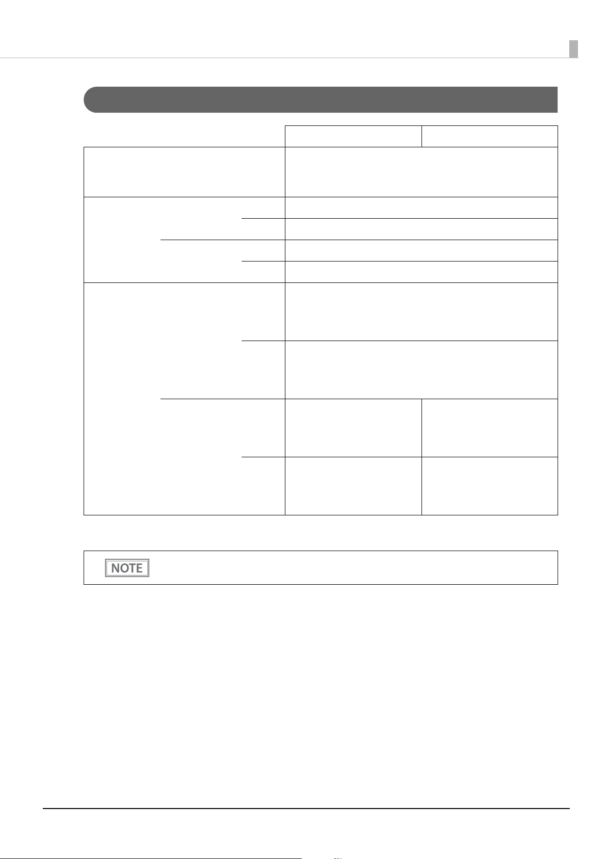
Character Specifications
80 mm {3.15"} width paper 58 mm {2.28"} width paper
Number of characters Alphanumeric characters: 95
Extended graphics: 128 × 43 pages (including user-defined page)
International characters: 18 sets
Appendix
Character
structure
(W x H dots)
Character size
Standard
Double-height
Double-width
Double-width
double-height
Standard mode
(default setting)
42 column mode
Standard mode
(default setting)
*
42 column mode
Font A 12 × 24 dots (Right-side dot space: 2)
Font B 9 × 17 (Right-side dot space: 2)
Font A 13 × 24 dots (Right-side dot space: 3)
Font B 9 × 17 dots (Right-side dot space: 2)
1.25 × 3.00 mm {0.05 × 0.12"}
Font A
Font B
Font A
Font B
1.25 × 6.00 mm {0.05 × 0.24"}
2.50 × 3.00 mm {0.10 × 0.12"}
2.50 × 6.00 mm {0.10 × 0.24"}
0.88 × 2.13 mm {0.03 × 0.08"}
0.88 × 4.26 mm {0.03 × 0.16"}
1.76 × 2.13 mm {0.06 × 0.08"}
1.76 × 4.26 mm {0.06 × 0.16"}
1.25 × 3.00 mm {0.05 × 0.12"}
1.25 × 6.00 mm {0.05 × 0.24"}
2.50 × 3.00 mm {0.10 × 0.12"}
2.50 × 6.00 mm {0.10 × 0.24"}
0.88 × 2.13 mm {0.03 × 0.08"}
0.88 × 4.26 mm {0.03 × 0.16"}
1.76 × 2.13 mm {0.06 × 0.08"}
1.76 × 4.26 mm {0.06 × 0.16"}
0.88 × 2.13 mm {0.03 × 0.08"}
0.88 × 4.26 mm {0.03 × 0.16"}
1.76 × 2.13 mm {0.06 × 0.08"}
1.76 × 4.26 mm {0.06 × 0.16"}
1.25 × 3.00 mm {0.05 × 0.12"}
1.25 × 6.00 mm {0.05 × 0.24"}
2.50 × 3.00 mm {0.10 × 0.12"}
2.50 × 6.00 mm {0.10 × 0.24"}
*: Space between characters is not included.
Characters can be scaled up to 64 times as large as the standard size.
Refer to the following URL regarding the character code table.
www.epson-biz.com/pos/reference/charcode/
78
Page 79

Paper Specifications
80 mm {3.15"} width paper 58 mm {2.28"} width paper
Paper types Specified thermal paper
Form Roll paper
Roll paper diameter Max.: 83 mm {3.27"}
Roll paper spool Inside: 12 mm {0.47"}, Outside: 18 mm {0.71"}
Size
Roll width when taken up 80 + 0.5/-1.0 mm {3.15 +0.02/-0.04"} 58 + 0.5/-1.0 mm {2.28 +0.02/-0.04"}
Paper width 79.5 ± 0.5 mm {3.13 ±0.02"} 57.5 ± 0.5 mm {2.26 ±0.02"}
Specified original paper type NTP080-80 NTP058-80
TF50KS-EY, TF60KS-E (NIPPON Paper Industries Co., Ltd.)
PD150R, PD160R, PD190R (OJI Paper Mfg. Co., Ltd.)
P220AGB-1 (Mitsubishi Paper Mills Limited.)
AF50KS-E (Jujo Thermal Oy)
Specified original paper type
F5041(48), F5041(55) (Mitsubishi HiTec Paper Flensburg GmbH)
KT55FA, KT48FA (Koehler Paper Group)
Appendix
Epson Certified Media List for Thermal Receipt Printers
U www.epson-biz.com/?content=sht_tm_media
• Paper must not be pasted to the roll paper spool.
• For the best print quality for each paper type, it is recommended to set the print density. (See
"Software Settings" on page 41.)
79
Page 80

Appendix
Printable Area
80 mm {3.15"} width paper printing
The maximum printable area of paper with a width of 79.5 ± 0.5 mm {3.13 ± 0.02"} is 72.1 ± 0.2 mm {2.84 ±
0.008"} (576 dots) and the approximate space is 3.0 mm {0.12"} on the left side on the left side and 4.5 mm
{0.18"} on the right side.
80
Page 81

Appendix
58 mm {2.28"} width paper printing
The maximum printable area of paper with a width of 57.5 ± 0.5 mm {2.26 ± 0.02"} is 52.6 ± 0.2 mm {2.07 ±
0.008"} (420 dots), and the approximate space is 3.0 mm {0.12"} on the left side and 2.0 mm {0.079"} on the right
side.
81
Page 82

Printing and Cutting Positions
Autocutter blade position
Approx. 27.1 mm {1.07"}
Approx.
10.5 mm
{0.41"}
Manual cutter position
Paper feed direction
Center of the print dotline
Printable area
Appendix
• The values above may vary slightly as a result of paper slack or variations in the paper. Take this
into account when setting the cutting position of the autocutter.
• When removing cut paper, the remaining roll paper is pulled at the uncut section and the pitch
of the next print may be reduced. When printing after cutting paper for prints with no pitch
reduction, feed the paper about 1 mm {16/406 inches} before printing.
• When leaving paper loaded for an extended period of time, make sure you feed about 30 mm of
paper. This can prevent paper from wrinkling and causing prints to be too light.
82
Page 83

Electrical Characteristics
Print ratio 80% 100%
Print example
Print length 30 mm {1.18"} 20 mm {0.79"}
58 mm {2.28"}
72 mm {2.83"}
Supply voltage 24VDC ± 7%
Rated current 1.5 A
If printing is continuously performed with a high print ratio, the overcurrent protection may be
activated and result in uneven print density or a low voltage error. Therefore, the printing length
must not exceed the following values when printing with high print ratio.
Print ratio: Number of dots being energized per one dot line / Total number of dots per one dot line
(576 dots)
Appendix
83
Page 84

Environmental Conditions
Relative
humidity
Operating
environment
range
Ambient temperature
10
20
40
60
80
90
0
0 1020304050
[%RH]
34°C {93.2°F}, 90%
40°C {104°F}, 65%
45°C {113°F}, 50%
[°C]
Appendix
Temperature/
Humidity
Operating 5 to 45°C {41 to 113°F}, 10 to 90% RH
(See the operating environment range below.)
Storage -10 to 50°C {14 to 122°F}, 10 to 90% RH (except for paper)
Acoustic noise (operating) Approx. 55 dB (bystander position)
Note: The values above are measured in the Epson evaluation condition.
Acoustic noise differs depending on the paper used, printing contents, and the
setting values, such as print speed or print density.
84
Page 85
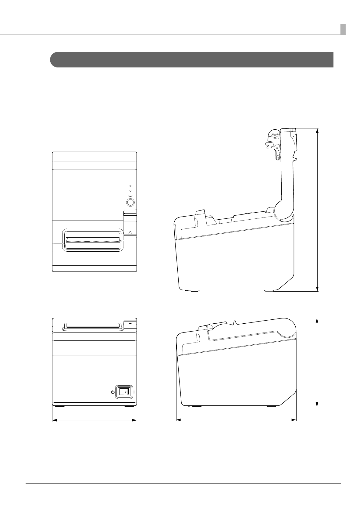
External Dimensions and Mass
269.5
146
199140
[Units: mm]
• Height: Approx. 146 mm {5.75"}
• Width: Approx. 140 mm {5.51"}
• Depth: Approx. 199 mm {7.83"}
• Mass: Approx. 1.7 kg {3.31 lb} (excluding roll paper)
Appendix
85
Page 86

Specifications of Interfaces and Connectors
Description
• Full-speed transmission at 12 Mbps [bps: bits per second]
• Plug & Play, Hot Insertion & Removal
USB Interface
USB interface connector
USB type-B connector
USB transmission specifications
Appendix
USB function
Item Specifications
Overall specifications According to USB 2.0 specifications
Transmission speed USB Full-Speed (12 Mbps)
Transmission method USB bulk transmission method
Power supply specifications USB self power supply function
Current consumed by USB bus 2 mA
USB packet size
(with full-speed connection)
USB device class Both USB vendor-defined class and USB printer class are supported.
To set the USB device class, see "Software Settings" on page 41.
USB bulk OUT (TM) 64 bytes
USB bulk IN (TM) 64 bytes
USB descriptor
Vendor ID
Product ID
String Descriptor
USB vendor-defined class USB printer class
04B8h 04B8h
0202h 0E28h
Manufacturer EPSON EPSON
Product TM-T20III TM-T20III
Serial number Character string based on the
product serial number
Character string based on the
product serial number
86
Page 87

RS-232 Serial Interface
Interface board specifications (RS-232-compliant)
Item Specifications
Data transfer method Serial
Synchronization Asynchronous
Handshaking Select one of the following in the software setting mode.
• DTR/DSR
• XON/XOFF
Signal level MARK -3V to -15V logic “1”/OFF
SPACE +3V to +15V logic “0”/ON
Bit length Select one of the following in the software setting mode.
• 7 bit
• 8 bit
Appendix
Transmission speed Select one of the following in the software setting mode.
2400/4800/9600/19200/38400/57600/115200 bps
[bps: bits per second]
Parity check Select one of the following in the software setting mode.
• Ye s
• No
Parity selection Select one of the following in the software setting mode.
• Even
• Odd
Stop bit 1 or more bits
However, the stop bit for data transfer from the printer is fixed to 1 bit.
Connector Printer side DSUB 25 pin (female)
87
Page 88

Functions of each connector pin
Appendix
Pin no.
1FG - Frame ground
2 TXD Output Transmission data
3 RXD Input Reception data
4 RTS Output Equivalent to DTR signal (pin 20)
6 DSR Input This signal indicates whether the host computer can receive data.
7 SG - Signal ground
20 DTR Output 1) When DTR/DSR control is selected, this signal indicates whether the printer is
Signal
name
Signal
direction
Function
SPACE indicates that the host computer can receive data. MARK indicates that
the host computer cannot receive data.
When DTR/DSR control is selected, the printer transmits data after confirming
this signal. (except if transmitted using some ESC/POS commands).
When XON/XOFF control is selected, the printer does not check this signal.
When you use this signal as the printer’s reset signal, the printer is reset when
the signal remains MARK for a pulse width of 1 ms or more.
BUSY.
•SPACE status
Indicates that the printer is ready to receive data.
•MARK status
Indicates that the printer is BUSY. Select the BUSY condition in the
software setting mode.
2) When XON/XOFF control is selected, this signal indicates that the printer is
properly connected and ready to receive data from the host.
•SPACE status
The signal indicates that the printer is properly connected and ready to
receive data from the host.
The signal is always SPACE, except in the following cases:
•During the period from when power is turned on to when the printer is
ready to receive data.
•While the self-test is in progress.
25 INT Input The printer is reset if the signal remains at SPACE for a pulse width of 1 ms or
more.
88
Page 89
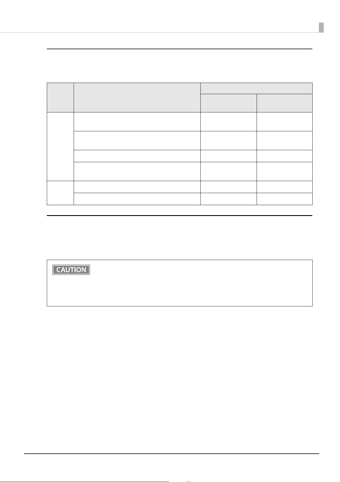
XON/XOFF
When XON/XOFF control is selected, the printer transmits the XON or XOFF signals as follows.
The transmission timing differs, depending on the BUSY condition.
BUSY condition
Signal Printer status
Receive buffer full
Receive buffer full/
Appendix
Offline
XON When the printer goes online after turning on the power
(or reset using the interface)
When the receive buffer is released from the buffer full
state
When the printer switches from offline to online - Transmit
When the printer recovers from an error using some
ESC/POS commands
XOFF When the receive buffer becomes full Transmit Transmit
When the printer switches from online to offline - Transmit
Transmit Transmit
Transmit Transmit
- Transmit
Code
The hexadecimal numbers corresponding to the XON/XOFF codes are shown below.
• XON code: 11H
• XOFF code: 13H
• When the printer goes from offline to online and the receive buffer is full, XON is not
transmitted.
• When the printer goes from online to offline and the receive buffer is full, XOFF is not
transmitted.
• When handshaking is set to DTR/DSR, XON is not transmitted as long as the printer is offline,
even if a receive buffer full state has been cleared.
89
Page 90

Appendix
Ethernet Interface
Communication specifications
10BASE-T/100BASE-TX
Support protocols
Protocols Usage
IP, ARP, ICMP, UDP, TCP Basic communication protocols
LP, LPR Printing protocols
TCP Socket Port Used to transfer printing data and printer status via (bidirectional) direct
socket communication.
HTTP/HTTPS Used by browsers to display and set module status
SNMP Used by dedicated and general MIB tools to acquire and set module and
printer status
ENPC Used to acquire and set module and printer status
DHCP Used to acquire the IP address
APIPA Used to assign the IP address
90
Page 91

Network parameters
Item Default settings
IP Address 192.168.192.168
Appendix
*
Subnet mask 255.255.255.0
Default gateway 0.0.0.0
IP address acquisition Automatic
APIPA Disabled
arp/ping Disabled
IP Address Printing Enabled
Socket Timeout 90 seconds
Standard Community Name (Read Only) "public"
Community name (Read Only) No
Community name (Read/Write) No
SNMP IP Trap 1 Disabled
SNMP IP Trap 2 Disabled
Communication mode Auto negotiation
IP Filter Disabled
*
*
* Initial value when “IP address acquisition” is set to “Manual.”
91
Page 92

Wireless LAN Interface (when OT-WL06 is used)
When using wireless LAN, make sure you disconnect the LAN cable. If a LAN cable is connected,
wireless LAN is disabled.
Specifications
• IEEE802.11b/g/n (2.4 GHz band) or IEEE802.11a/b/g/n (2.4 GHz or 5 GHz band) compliant
• Infrastructure mode is supported.
Communication Standard
• IEEE802.11a (5 GHz)
• IEEE802.11b (2.4 GHz)
• IEEE802.11g (2.4 GHz)
• IEEE802.11n (2.4 GHz / 5 GHz)
Appendix
• IEEE802.11ac (5 GHz)
Security
• WEP
• WPA-PSK(AES): WPA-PSK(AES),WPA-PSK(TKIP),WPA2-PSK(AES),WPA2-PSK(TKIP) can be
connected
• WPA2-PSK: WPA2-PSK(AES),WPA2-PSK(TKIP) can be connected
• WPA2-Enterprise
Settings in SimpleAP mode (Factory default settings)
Parameter Setting value
SSID EPSON_Printer
Passphrase 12345678
IP Address 192.168.192.168
Subnet mask 255.255.255.0
* In SimpleAP mode, DHCP Server is working and assigns IP address to host automatically.
92
Page 93

Appendix
Settings in Standard Mode
Parameter Default setting
Communication standard 802.11b/g/n
Network mode Infrastructure mode
SSID EPSON_Printer
Encryption type WPA2-PSK
Passphrase EpsonNet
IP Address Automatically acquired by DHCP
Printing communication protocol
• LP, LPR: Transfers printing data
• TCP Socket Port: Transfers printing data and printer status via bidirectional direct socket communication.
LP, LPR
• Max. simultaneous connections: 6
• Number of connections for which printing is available: 1 (Other users need to wait until printing is
completed.)
• Time out: 90 sec. (changeable)
• Job cancel: Not available
• Banner printing: Not available
Socket communication
• Port type: TCP communication port for direct printing
• Port number: 9100
• Port communication direction: bidirectional
• Max. simultaneous connections: 6
• Number of connections for which printing is available: 1 (Other users need to wait until printing is
completed.)
• Time out: 90 sec. (changeable)
Notes on Using the Wi-Fi Model
• Keep the printer away from the devices, such as kitchen microwaves, that may cause radio wave interference.
• Use channels that are away from the frequency bands that may cause radio wave interference.
• Place shields between the printer and the devices that may cause radio wave interference.
• Select either 2.4 GHz or 5 GHz, whichever is free from radio wave interference.
• In auto channel setting for the access point, do not select a channel in which the devices may cause radio
wave interference.
93
Page 94

Appendix
Notes on Wi-Fi connection
Because not all the combinations of the printer and Wireless LAN units have been checked for operation, the
operation of the printer in combination with all the Wireless LAN units is not guaranteed. Especially in the
adhoc mode, the printer may not operate normally, depending on the combination of the device to connect
with. Be sure to carry out evaluation of the operation before use.
Notes on use
When you initialize or change the printer settings, the printer is reset to reflect the settings. It may take about
one minute depending on the network settings or environment. Also, your application may indicate power off
during the time waiting for reset. In that case, wait for about one minute, and then reconnect to the printer.
Where Wi-Fi communication is in heavy traffic, your application may falsely recognize that the communication
is disconnected and indicate power off due to response delay. In that case, disable Power Save to improve the
trouble.
94
 Loading...