

Describes how to control the scanner and necessary information
when you develop applications.
Describes setup and installation of the product.
Describes how to handle the product.
Describes features and general specifications for the product.
Technical Reference Guide
Describes the interface and character code tables.
Product Overview
Setup
Application Development Information
Handling
Appendix
M00046002
Rev. C

Cautions
• No part of this document may be reproduced, stored in a retrieval system, or transmitted in any form
or by any means, electronic, mechanical, photocopying, recording, or otherwise, without the prior
written permission of Seiko Epson Corporation.
• The contents of this document are subject to change without notice. Please contact us for the latest
information.
• While every precaution has been taken in the preparation of this document, Seiko Epson Corporation assumes no responsibility for errors or omissions.
• Neither is any liability assumed for damages resulting from the use of the information contained
herein.
• Neither Seiko Epson Corporation nor its affiliates shall be liable to the purchaser of this product or third
parties for damages, losses, costs, or expenses incurred by the purchaser or third parties as a result of:
accident, misuse, or abuse of this product or unauthorized modifications, repairs, or alterations to this
product, or (excluding the U.S.) failure to strictly comply with Seiko Epson Corporation’s operating
and maintenance instructions.
• Seiko Epson Corporation shall not be liable against any damages or problems arising from the use of
any options or any consumable products other than those designated as Original Epson Products or
Epson Approved Products by Seiko Epson Corporation.
Trademarks
EPSON is a registered trademark of Seiko Epson Corporation.
Exceed Your Vision is a registered trademark or trademark of Seiko Epson Corporation.
©Seiko Epson Corporation 2012-2017. All rights reserved.
2
For Safety
Key to Symbols
The symbols in this manual are identified by their level of importance, as defined below. Read
the following carefully before handling the product.
You must follow warnings carefully to avoid serious bodily injury.
WARNING
Provides information that must be observed to prevent damage to the equipment or loss of
data.
CAUTION
Possibility of sustaining physical injuries.
Possibility of causing physical damage.
Possibility of causing information loss.
Provides information that must be observed to avoid damage to your equipment or a
malfunction.
Provides important information and useful tips.
3

Warnings
WARNING
To avoid risk of electric shock, do not set up this product or handle cables during
a thunderstorm.
Never insert or disconnect the power plug with wet hands.
Doing so may result in severe shock.
Handle the power cable with care.
Improper handling may lead to fire or electric shock.
Do not modify or attempt to repair the cable.
Do not place any heavy object on top of the cable.
Avoid excessive bending, twisting, and pulling.
Do not place the cable near heating equipment.
Check that the plug is clean before plugging it in.
Be sure to push the plug all the way in.
Be sure to use the specified AC adapter.
Connection to an improper power source may cause fire or shock.
Do not place multiple loads on the power outlet.
Overloading the outlet may lead to fire.
Shut down your equipment immediately if it produces smoke, a strange odor, or
unusual noise.
Continued use may lead to fire. Immediately unplug the equipment and contact your
dealer or a Seiko Epson service center for advice.
Never attempt to repair this product yourself.
Improper repair work can be dangerous.
Never disassemble or modify this product.
Tampering with this product may result in injury or fire.
Do not allow foreign matter to fall into the equipment.
Penetration by foreign objects may lead to fire.
If water or other liquid spills into this equipment, do not continue to use it.
Continued use may lead to fire. Unplug the power cord immediately and contact your
dealer or Epson service center for advice.
Do not use aerosol sprayers containing flammable gas inside or around this
product.
Doing so may cause fire.
4

Cautions
CAUTION
Do not connect cables in ways other than those mentioned in this manual.
Different connections may cause equipment damage or fire.
Be sure to set this equipment on a firm, stable, horizontal surface.
The product may break or cause injury if it falls.
Do not use this product in locations subject to high humidity or dust levels.
Excessive humidity and dust may cause equipment damage or fire.
Do not place heavy objects on top of this product. Never stand or lean on this
product.
Equipment may fall or collapse, causing breakage and possible injury.
Take care not to injure your fingers on the manual cutter
When you remove printed paper
When you perform other operations, such as loading/replacing roll paper
Before leaving the product unused for an extended period, make sure the ink
cartridge is installed, turn the product off using the power button, and unplug the
product to ensure safety.
Do not connect a telephone line to the drawer kick-out connector; otherwise the
product and the telephone line may be damaged.
Restriction of Use
When this product is used for applications requiring high reliability/safety such as
transportation devices related to aviation, rail, marine, automotive, etc.; disaster prevention
devices; various safety devices etc; or functional/precision
product only after giving consideration to including fail-safes and redundancies into your
design to maintain safety and total system reliability. Because this product was not intended for
use in applications requiring extremely high reliability/safety such as aerospace equipment,
main communication equipment, nuclear power control equipment, or medical equipment
related to direct medical care, etc., please make your own judgment on this product’s suitability
after a f
ull evaluation.
devices, etc., you should use this
5

About this Manual
Aim of the Manual
This manual was created to provide information on development and design of scanner
applications for developers.
Manual Content
The manual is made up of the following sections:
Chapter 1
Chapter 2
Chapter 3
Chapter 4
Appendix
Product Overview
Setup
Application Development Information
Handling
Specifications of USB Interface
Character Code Tables
6

Contents
■ For Safety...............................................................................................................................3
Key to Symbols ....................................................................................................................................... 3
Warnings ................................................................................................................................................. 4
Cautions.................................................................................................................................................. 5
■ Restriction of Use...................................................................................................................5
■ About this Manual ................................................................................................................6
Aim of the Manual................................................................................................................................. 6
Manual Content .................................................................................................................................... 6
■ Contents ................................................................................................................................7
Product Overview ........................................................................11
■ Features...............................................................................................................................11
■ Product Configuration........................................................................................................12
Color...................................................................................................................................................... 12
Attachments ........................................................................................................................................ 12
■ Part Names and Functions.................................................................................................13
Power Button ........................................................................................................................................ 14
Control Panel ....................................................................................................................................... 14
Connectors........................................................................................................................................... 16
■ Offline ..................................................................................................................................17
■ Processing Modes for Cut Sheet Paper ............................................................................18
High-Speed Mode ............................................................................................................................... 18
Confirmation Mode............................................................................................................................. 20
■ Selectable Functions for Processing Cut Sheet ...............................................................24
■ Error Status...........................................................................................................................26
Automatically Recoverable Errors ..................................................................................................... 26
Recoverable Errors .............................................................................................................................. 27
Unrecoverable Errors ........................................................................................................................... 28
■ NV Memory (Non-Volatile Memory) ................................................................................29
NV Graphics Memory.......................................................................................................................... 29
User NV Memory .................................................................................................................................. 29
Memory Switches................................................................................................................................. 29
R/E (Receipt Enhancement) .............................................................................................................. 30
User-defined Page............................................................................................................................... 30
Maintenance Counter ........................................................................................................................ 30
■ Maintenance Counter........................................................................................................31
■ Product Specifications .......................................................................................................32
Printing Specifications ......................................................................................................................... 34
7

Character Specifications ....................................................................................................................36
Scanner Specifications ........................................................................................................................37
MSR (Factory Option)...........................................................................................................................38
Paper Specifications ............................................................................................................................39
Printable Area.......................................................................................................................................41
Printing and Cutting Positions for Roll Paper ..................................................................................... 42
Scannable Area ...................................................................................................................................43
MICR Readable Area ..........................................................................................................................45
Area for Electric Endorsement ............................................................................................................45
Environmental Conditions ...................................................................................................................46
Reliability................................................................................................................................................47
External Dimensions and Mass ............................................................................................................48
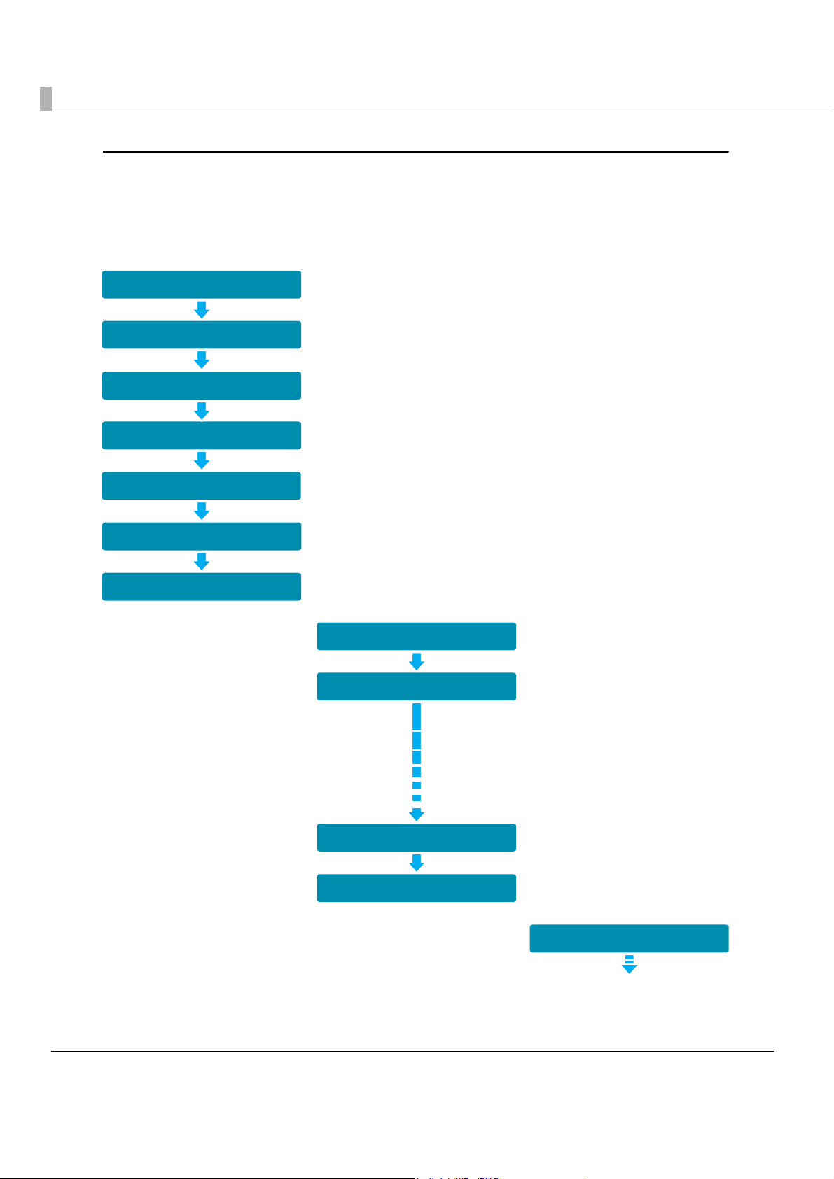
Setup .............................................................................................50
■ Flow of Setup ...................................................................................................................... 50
■ Installing the Product ......................................................................................................... 51
Important Notes on Installation ..........................................................................................................51
■ Connecting the Product to the Host Computer .............................................................. 52
■ Connecting the Power Supply Unit................................................................................... 53
■ Installing and Replacing the Ink Cartridge ..................................................................... 54
■ Installing and Replacing the Roll Paper........................................................................... 56
■ Connecting the Cash Drawer ........................................................................................... 57
Connecting the Drawer Kick-out Cable ...........................................................................................57
■ Setting the Memory Switches and R/E ............................................................................. 59
Functions ...............................................................................................................................................60
Application Development Information......................................64
■ Software .............................................................................................................................. 64
Operating Environment ....................................................................................................................... 64
Software for Windows .......................................................................................................................... 65
Software for Linux .................................................................................................................................66
How to Get Drivers, Utilities, and Manuals .........................................................................................66
■ Setting/Checking Modes .................................................................................................. 67
Self-test Mode.......................................................................................................................................67
NV Graphics Print Mode...................................................................................................................... 69
Receipt Enhancement Information Print Mode ............................................................................... 71
Memory Switch Setting Mode.............................................................................................................72
8

Handling .......................................................................................73
■ Turning On/Off the Product................................................................................................73
Turning On ............................................................................................................................................ 73
Turning Off ............................................................................................................................................ 73
■ Opening Covers .................................................................................................................74
Opening the Roll Paper Cover........................................................................................................... 74
Opening the Ink Cartridge Cover...................................................................................................... 74
Opening the MICR Cover................................................................................................................... 75
Opening the Rear Cover .................................................................................................................... 75
Opening the Scanner Cover.............................................................................................................. 76
■ Processing Cut Sheet Paper ..............................................................................................77
Flow of Single Pass Processing............................................................................................................ 77
Important Notes on Processing Cut Sheet Paper ............................................................................ 77
Inserting Cut Sheet Paper ................................................................................................................... 78
Ejecting Cut Sheet Paper ................................................................................................................... 79
■ Scanning ID Cards..............................................................................................................80
■ Reading Magnetic Stripe Cards........................................................................................81
■ Cleaning..............................................................................................................................82
Cleaning the Thermal Head ............................................................................................................... 82
Cleaning the Ink-Jet Head ................................................................................................................. 82
Cleaning the MICR Head ................................................................................................................... 83
Cleaning the Scanner ......................................................................................................................... 83
Cleaning the Product Case ............................................................................................................... 84
■ Troubleshooting ..................................................................................................................86
Error LED Is On or Flashing ................................................................................................................... 86
Paper or ID Card Is Jammed.............................................................................................................. 86
Printout Is Faint ..................................................................................................................................... 87
Reading/Scanning Is not Normal....................................................................................................... 87
Roll Paper Cover Will not Open ......................................................................................................... 88
■ Preparing for Transport.......................................................................................................89
Install the transportation cartridge .................................................................................................... 89
Pack the scanner................................................................................................................................. 89
Appendix......................................................................................90
■ Specifications of USB Interface .........................................................................................90
USB Interface (Type B) ......................................................................................................................... 90
Optional USB Interface (Type A) ........................................................................................................ 90
■ Character Code Tables .....................................................................................................91
Common to All Pages ......................................................................................................................... 92
Page 0 [PC437: USA, Standard Europe]............................................................................................93
Page 1 (Katakana).............................................................................................................................. 94
9

Page 2 (PC850: Multilingual) ...............................................................................................................95
Page 3 (PC860: Portuguese)...............................................................................................................96
Page 4 (PC863: Canadian-French)....................................................................................................97
Page 5 (PC865: Nordic) .......................................................................................................................98
Page 16 (WPC1252) ............................................................................................................................. 99
Page 17 (PC866: Cyrillic #2) .............................................................................................................. 100
Page 18 (PC852: Latin2) ....................................................................................................................101
Page 19 (PC858: Euro) ....................................................................................................................... 102
Page 255 (User-Defined Page) .........................................................................................................103
International Character Sets .............................................................................................................104
10

Chapter 1 Product Overview
Product Overview
This chapter describes features and specifications of the TM-S9000MJ.
Features
This compact, full-scale, up-grade hybrid product integrates functions of printing, check
computerization, personal ID image reading, and magnetic card stripe reading (optional)
required mainly for reception work at banks.
The main features are as follows.
•Small-footprint
• Roll paper printing function
Autocutter as standard equipment
Paper-saving function
•Check endorsement, cut sheet paper (cut sheet receipts, cashier’s check) printing
Ink-jet printing of multiple line and high resolution with 360 nozzle and 180 dpi
•Check magnetic ink character reader (E13B, CMC7) (supported by the driver.)
ICapturing image on the face and back of cut sheet paper and personal ID (such as driver’s license)
•Capability in obtaining binary (only cut sheet paper is supported.), grayscale, color, and
infrared light source images
•Auto sheet feeder
•Double feed detection for cut sheet paper
•Function to judge improper insertion of checks
•IQA (Image Quality Assurance) (Supported by the driver)
•OCR (Opti
driver)
•High-speed USB (USB 2.0 compliant) port
•Maintenance counter that is convenient for remote maintenance
onal Character Recognition) (OCR-A font, OCR-B font, barcodes) (Supported by the
1
•Buzzer
•Connection to a cash drawer
•Low ink detection, notifications to request replacing the in
•Paper separation using two exit pockets (supported by the two-pocket models only.)
•Magnetic stripe reader (factory option)
•USB-HUB (factory option)
k cartridge
11

Product Configuration
The TM-S9000MJ differs in function and equipment depending on the combinations of the
following specifications.
•Document processing speed: 110 dpm or 200 dpm
•Number of document exit pockets: 1 pocket or 2 pockets
•Whether or not the product has an MSR (Magnetic Stripe Reader) and USB (Type A)
connectors
Processing speed
110 dpm 1 pocket Installed Installed
200 dpm 1 pocket Installed Installed
dpm: documents per m
inute
Number of
document pockets
Not installed Not installed
2 pockets Installed Installed
Not installed Not installed
Not installed Not installed
2 pockets Installed Installed
Not installed Not installed
MSR
Color
EDG (Epson Dark Gray)
USB (Type A)
connectors
Attachments
• Thermal roll paper (for operation check)
•USB cable
•2 dedicated ink cartridges (Model: SJIC18(K))
•AC cable*
•AC adapter
•Setup Guide
• User’s Manual
* May not be included depending on the product model.
12
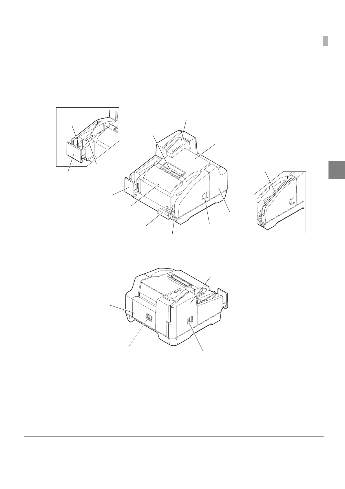
Part Names and Functions
Control panel
Manual cutter
Roll paper cover
MSR
Sub pocket
Rear cover open lever
Main pocket
Rear cover
Pocket guide
Pocket guide
Ink cartridge cover
ASF guide
Power button
MICR cover open lever
Scanner cover open lever
MICR cover
Scanner cover
Two-pocket model
MSR-equipped model
(See "Control Panel" on page 14.)
Chapter 1 Product Overview
1
13
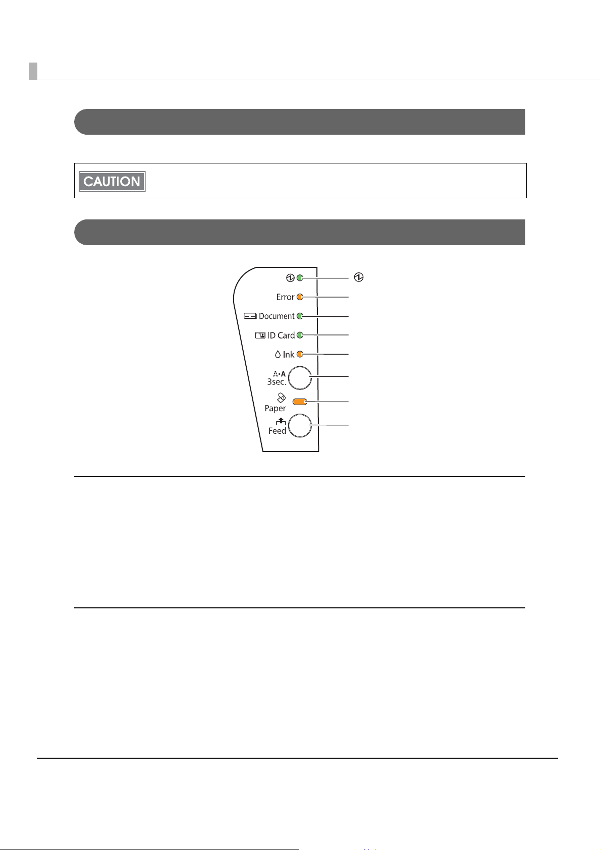
Power Button
(Power) LED
Error LED
Document LED
ID Card LED
Ink LED
Cleaning button
Paper LED
Feed button
Turns the product on or off.
Be sure not to turn off the product or open the covers while the Power LED is flashing.
Control Panel
Power LED (Green)
•Lights when the power supply is on.
•Flashes rapidly while some operations such as turning power on, ink charging, or cleaning,
are executed.
• Flashes slowly while turning power off.
•Goes out when the power supply is turned off.
Error LED (Orange)
•Lights when the product is offline (except during paper feeding using the Feed button, during
self-test, and during ink-jet head cleaning).
•Flashes when an error occurs. (For details about the flash codes, see "Error Status" on page 26.)
•Goes out during regular operation (online).
14

Chapter 1 Product Overview
Document LED (Green)
•Lights when the product is ready to process cut sheet paper in the ASF or while the product is
processing cut sheet paper.
•Flashes when the product is waiting for cut sheet paper insertion.
•Goes out except for the cases above.
ID Card LED (Green)
•Lights when ID card is set and the product is ready to process it.
•Flashes when the product is waiting for ID card insertion or removal.
•Goes out except for the cases above.
Ink LED (Orange)
•Lights when no ink cartridge is installed or it is time to replace the ink cartridge.
1
•Flashes when ink is low.
•Goes out when the ink cartridge is installed and remaining ink is enough.
Cleaning button
Pressing this button for 3 seconds or more starts the ink-jet head cleaning. (See "Cleaning the Ink-
Jet Head" on page 82
.)
Paper LED (Orange)
•Lights when the roll paper is out or almost out.
•Flashes when the product is waiting for test printing on the roll paper.
•Goes out when the remaining roll paper is enough.
Feed button
Pressing this button feeds the roll paper.
15
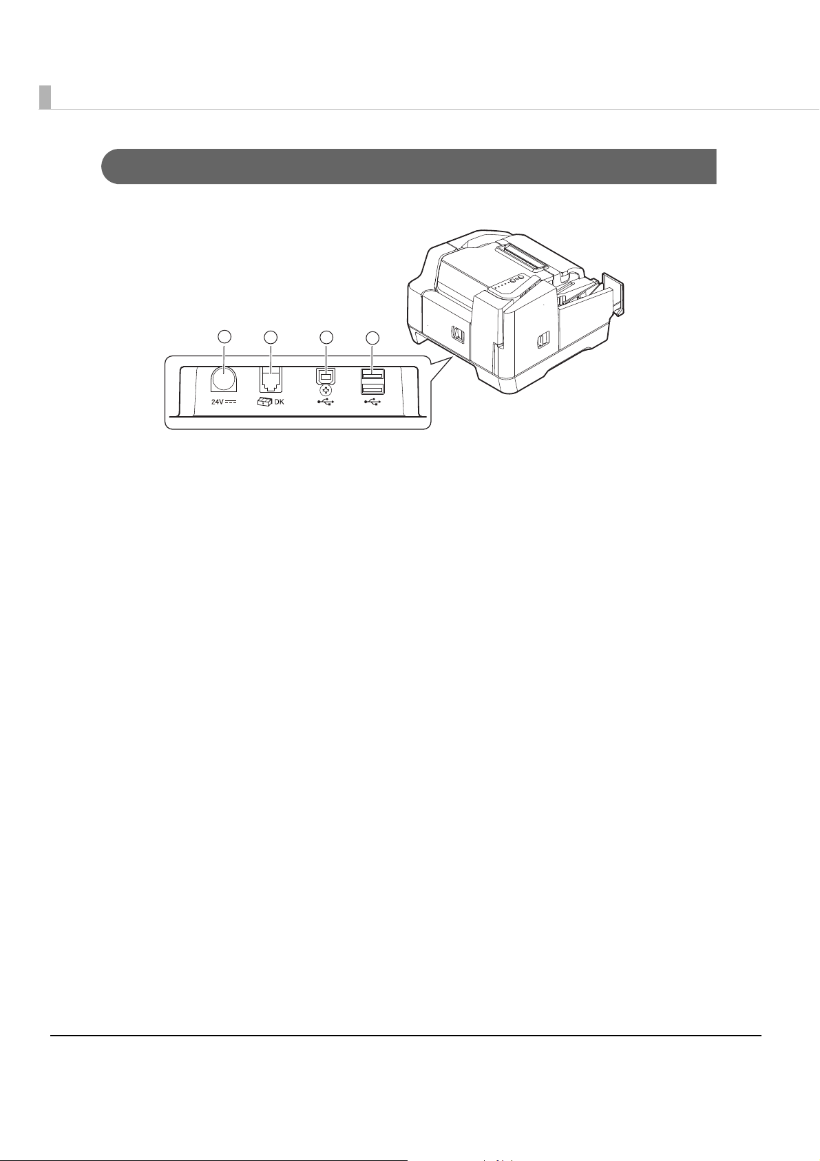
Connectors
1
23
4
All cables are connected to the connector panel on the lower rear of the product.
•Power supply connector (
• Drawer kick-out connector (➁): Connects the cash drawer.
•USB connector (Type B) (➂): Connects the product with the host computer.
•USB connectors (Type A)* (
* Factory option
➀): Connects the power supply unit.
➃): Connects USB devices.
16

Offline
The TM-S9000MJ automatically goes offline under the following conditions:
•During initialization after:
Power on (including resetting with the interface)
Removal of error causes
•When any of the following covers are opened:
Ink cartridge cover
Roll paper cover
MICR cover
Rear cover
Scanner cover
•While the roll paper is fed using the FEED button
•When no ink cartridge is installed
•When it is time to replace the ink cartridge
•During self-test
Chapter 1 Product Overview
1
•During the ink-jet head cleaning
•When an error has occurred
•During macro command execution
•When the product
stops printing on the roll paper due to a roll paper end
For MSR equipped models, reading magnetic stripe card is possible, regardless of whether
the product is online or offline.
17

Processing Modes for Cut Sheet Paper
Fed from the ASF
Check for double feeding
MICR reading
Ink jet printing
Capturing image on both sides
Ejection of the document
Fed from the ASF
Check for double feeding
MICR reading
Fed from the ASF
Check for double feeding
MICR reading
Ink jet printing
Caputuring image on both sides
Ejection of the document
<First document>
<Second document>
<Third document>
The TM-S9000MJ has the following processing modes that are selectable with the driver in
accordance with how you want to use the product with cut sheet paper.
•High-speed mode
•Confirmation mode (with overlap/without overlap)
For detailed information about processing modes, see the TM-S9000MJ API Reference
Guide.
High-Speed Mode
This mode selects pockets and specifies whether to continue processing based on conditions
specified prior to scanning.
18

Chapter 1 Product Overview
<First document>
Fed from the ASF
Check for double feeding
MICR reading
Ink jet printing
Capturing image on both sides
Backward paper feeding*
Switching of the pocket
Ejection of the document
<Second document>
<Third document>
Fed from the ASF
Check for double feeding
Ejection of the document
Fed from the ASF
Switching of the pockets
*: Occurs depending on some
conditions.
When ejecting into the sub pocket (only for two-pocket models)
When documents are sorted into the two ejection pockets, a document is fed backward to the
pocket switching position and then ejected into a pocket if the ejection pocket is required to be
switched and the document is long. In that case, the processing slows down.
1
19

Confirmation Mode
<First document>
Fed from the ASF
Check for double feeding
MICR reading
Ink jet printing
Capturing image on both sides
Stop of paper feeding*
Ejection of the document
<Second document>
<Third document>
Fed from the ASF
Check for double feeding
Ejection of the document
Fed from the ASF
Stop of paper feeding*
* Waits for a command from the
application.
This mode selects pockets and specifies whether to continue processing according to commands
from the application for each scan.
Confirmation mode with overlap
The product starts feeding the next document while ejecting the current document into a pocket.
20

Chapter 1 Product Overview
*1 Waits for a command from the
application.
*
2
Occurs depending on some
conditions.
When ejecting into the sub pocket (only for two-pocket models)
When the two-pocket model receives a command to eject a document into a pocket, the
processing slows down because it feeds the document backward to the pocket switching
position and ejects it into a pocket.
<First document>
Fed from the ASF
Check for double feeding
MICR reading
Ink jet printing
Capturing image on both sides
1
Stop of paper feeding*
Backward paper feeding*
Switching of the pockets
Ejection of the document
1
2
<Second document>
Fed from the ASF
Check for double feeding
Switching of the pockets
<Third document>
Ejection of the document
Fed from the ASF
21
Confirmation mode without overlap
<First document>
Fed from the ASF
Check for double feeding
MICR reading
Ink jet printing
Capturing image on both sides
Stop of paper feeding*
Ejection of the document
<Second document>
<Third document>
Fed from the ASF
Check for double feeding
Ejection of the document
Fed from the ASF
Stop of paper feeding*
Ejection of the document
* Waits for a command from the
application.
The product starts feeding the next cut sheet paper after the current cut sheet paper has been
stored completely into the pocket.
22

Chapter 1 Product Overview
<First document>
Fed from the ASF
Check for double feeding
MICR reading
Ink jet printing
Capturing image on both sides
Stop of paper feeding*
Backward paper feeding*
Switching of the pockets
Ejection of the document
<Second document>
<Third document>
Fed from the ASF
Check for double feeding
Ejection of the document
Fed from the ASF
Switching of the pockets
2
1
*1: Waits for a command
from the application.
*
2
: Occurs depending on
some conditions.
When ejecting into the sub pocket (only for two-pocket models)
When the two-pocket model receives a command to eject the document into the sub pocket, the
processing slows down because it feeds the cut sheet paper backward to the pocket switching
position and ejects it into the sub pocket.
1
23

Selectable Functions for Processing Cut Sheet
The TM-S9000MJ has the following functions that are selectable with the driver in accordance
with how you want to use the product with cut sheet paper. Settings with an application are also
available for the pocket ejection and processing continuance in the confirmation mode.
•Pocket ejection (on
Ejects the document to the Main pocket
Ejects the document to the Sub pocket
Waterfall*
ly for two-pocket models)
•Processing continuance
Continues processing
Ejects the document and stops processing
Stops processing without ejecting the document
• Electric endorsement
Performs electric endorsement
Does not perform electric endorsement
* When the ejection pocket is near-full, the documents are automatically ejected to the other pocket.
Processing Mode:
This mode specifies whether or not to use Pocket ejection or Processing continuance
High-speed
mode
Confirmation
mode
depending on the conditions set before scanning starts.
This allows the application to operate at high speed as it does not need to specify
operations for the next document for each scan. These conditions can be judged by the
host computer (processing in the driver) or by the firmware.
This mode specifies whether or not to use Pocket ejection or Processing continuance
depending on the instructions from the application. If there are no instructions from the
application, operations can also be performed by using the settings made beforehand.
24

Chapter 1 Product Overview
Functions and Judgment Conditions to be Selected in Each Processing Mode:
Processing
Modes
Judgment Selectable Functions
Judged by F/W When judgments are made from the following conditions only.
High-speed
mode
Judged by Driver The following conditions are judged at the same time as well as the
Confirmation
mode
Judged by
Application
Processing speed limitation:
Processing
Modes
Judgment Description
• Detecting double feeding
• Detecting incorrect insertion
• (Check paper)
• Detecting magnetic waveform
• Detecting external noise
• Print result that exceeds the paper length
conditions in the cell above.
• “?” in MICR reading
• IQA judgment
• Barcode recognition result
Functions are judged by application software
1
High-speed
mode
Confirmation
mode
Judged by F/W Since operations can be performed with judgment by the firmware,
without judgment by the host computer, operations can be
performed at a high speed.
However, back feeding occurs when ejecting the document into the
sub pocket for two-pocket models. Therefore, the speed decreases
when the number of sub pocket ejections increases.
Judged by Driver Performance declines when the conditions need to be judged by
the driver.
Judged by
Application
When conditions for scanned images, MICR text strings, and so on
are judged by the application, since the product waits for
instructions from the application, the processing speed changes for
each scan as the application returns instructions to the driver.
Furthermore, performance changes depending on whether or not
to overlap the next document upon instructions from the
applications.
25

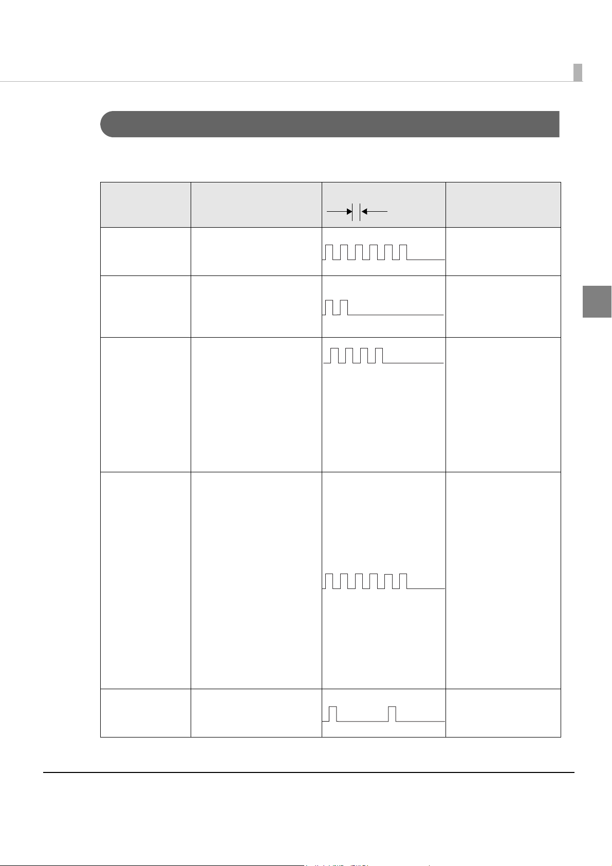
Error Status
Approx. 320 ms
When an error occurs, the printer stops operating, goes offline, and the Error LED flashes.
There are three possible error types: automatically recoverable errors, recoverable errors, and
unrecoverable errors.
Automatically Recoverable Errors
Printing is no longer possible when automatically recoverable errors occur. They can be
recovered easily, as described below.
Error LED flash code
Error Error description
Recovery measure
Roll paper cover
open error*
Print head high
temperature
r*
erro
Print head low
temperature
r*
erro
*1 The memory switch must be set to auto recoverable error.
*2 If a drive circuit error occurs because of extreme temperatures, it is an unrecoverable error.
1
2
2
While printing on the roll
paper, the roll paper
cover was opened.
The temperature of the
print head is extremely
high.
The temperature of the
print head is extremely
low.
Close the roll paper
cover.
Recovers
automatically when
the print head cools.
Recovers
automatically when
the print head warms.
26
Chapter 1 Product Overview
Approx. 320 ms
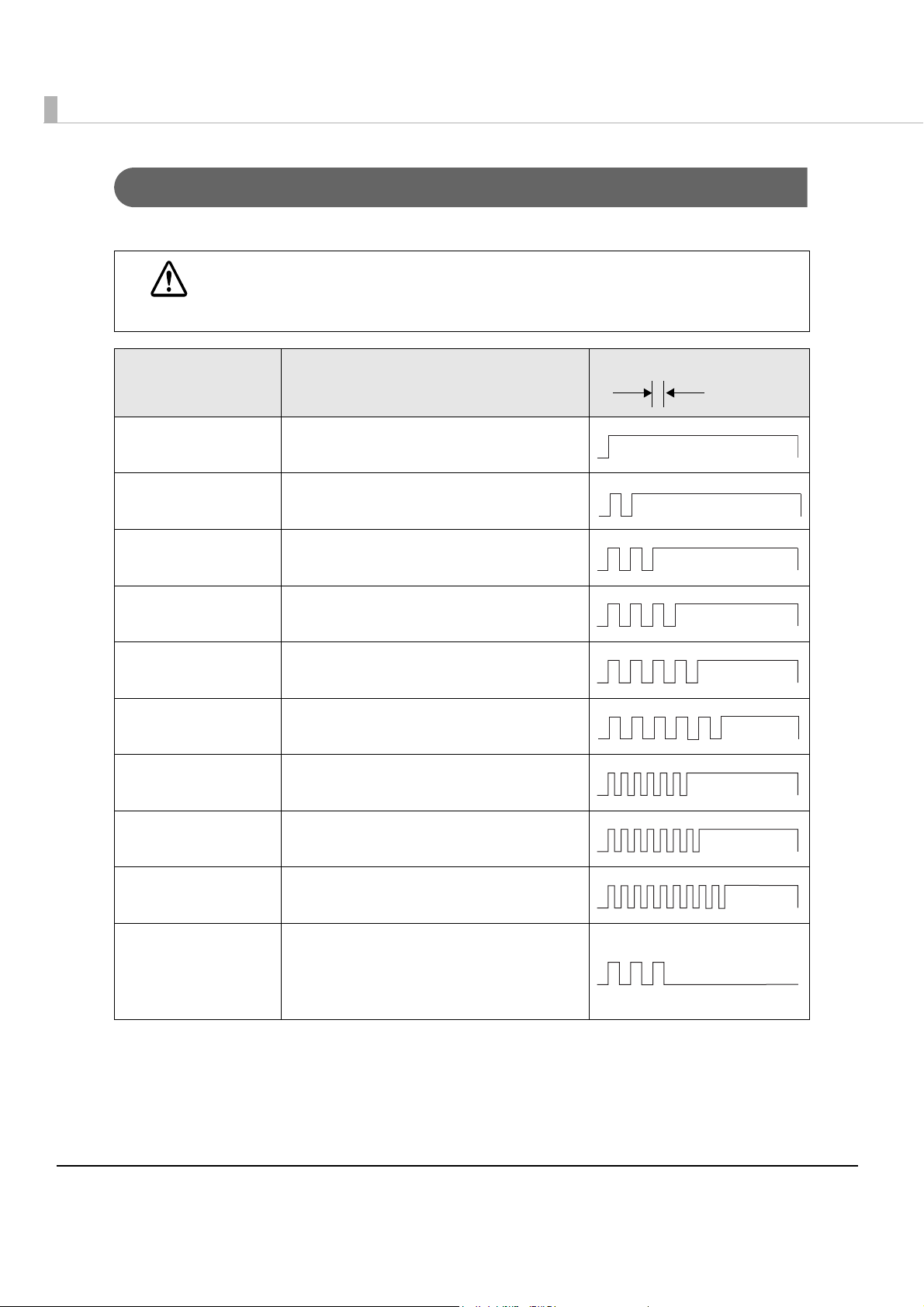
Recoverable Errors
Processing is no longer possible when recoverable errors occur. They can be recovered easily by
sending an error recovery command from the driver after eliminating the cause of the error.
Error LED flash code
Error Error description
Recovery measure
Roll paper cover
open error*
Mechanism
position error
Cut sheet paper
jam error
Cut sheet paper
feed error
While printing on the roll
paper, the roll paper
cover was opened.
The home position of the
hopper or the pocket
switching board cannot
be detected.
The check is not ejected
after feeding a specified
amount of paper.
Feeding from the ASF
failed.
A cut sheet paper/card
jam was detected.
Too short/long paper
was detected.
Double feeding of cut
sheet paper occurred.
Cut sheet paper was
inserted upside down or
back to front.
Selected that incorrect
cut sheet paper feeding
to cause an error in
confirmation mode.
Data that is longer than
the length of the cut
sheet paper was
specified.
Noise was detected
during MICR reading.
Recovers with a
command with the roll
paper cover closed.
Recovers with a
command after the
error cause is
eliminated.
Recovers with a
command after the
error cause is
eliminated.
Recovers with a
command after the
error cause is
eliminated.
1
Auto-cutter error The home position of the
* The memory switch must be set to recoverable error.
auto-cutter cannot be
detected.
Recovers after the
error cause is
eliminated.
27
Unrecoverable Errors
Approx.320 ms
Processing is no longer possible when unrecoverable errors occur. The scanner must be repaired.
Turn off the power immediately when unrecoverable errors occur.
CAUTION
Error LED flash code
Error Error description
Drive circuit error Internal circuit does not work correctly.
There is an abnormality in the thermistor.
Read/Write error After R/W checking, the printer does not
work correctly.
High voltage error The power supply voltage is extremely
high.
Low voltage error The power supply voltage is extremely low.
CPU execution error The CPU executes an incorrect address.
Communication
device error
IJ mechanism error Ink jet print mechanism does not work
Double feeding
detector noise error
Double feeding
detector error
Maintenance error The pump rotates more times than
USB does not work correctly.
correctly.
The double feeding detector detected a
noise.
The double feeding detector does not
work correctly.
specified.
The absorbed amount of the ink
absorber is more than specified.
28

Chapter 1 Product Overview
NV Memory (Non-Volatile Memory)
The printer's NV memory stores data even after the printer power is turned off. NV memory
contains the following memory areas for the user:
•NV graphics memory
• User NV memory
•Memory switches
•Receipt Enhancement (R/E)
•User-defined page
•Maintenance counter
As a guide when you program applications, NV memory should be rewritten 10 or fewer
times a day.
NV Graphics Memory
Graphics, such as logos to be printed on receipts, can be stored to enable high speed graphic
printing.
Use the TM-S9000 Utility to register graphics. You can also print and confirm the registered
graphics in the TM-S9000 Utility or NV graphics memory print mode.
For detailed information about the TM-S9000 Utility, see the TM-S9000 Utility User’s
Manual.
For information about how to use the NV graphics memory print mode, see
Graphics Print Mode" on page 69
.
"NV
User NV Memory
You can store and read text data for multiple purposes, such as for storing a note including
customizing or maintenance information of the printer.
1
Memory Switches
With the memory switches, which are software switches for the printer, you can configure
various settings of the printer.
For information about the memory switches, see
page 59
.
"Setting the Memory Switches and R/E" on
29

R/E (Receipt Enhancement)
Graphics, such as logos, can be printed on top or bottom of receipts by setting R/E.
For information about R/E settings, see
"Setting the Memory Switches and R/E" on page 59.
User-defined Page
You can store character data in the user-defined page (character code table: page 255) so that you
can also print characters not resident in the printer.
Maintenance Counter
With this function, printer information, such as the number of lines fed, the count of thermal
head energizing, and printer operation time after the printer starts working, is automatically
stored in NV memory. You can read or reset the information with the TM-S9000 Utility or the
API of t
For information about maintenance counter, see
he TM-S9000 Driver to use it for periodical checks or part replacement.
"Maintenance Counter" on page 31.
30

Chapter 1 Product Overview
Maintenance Counter
The TM-S9000MJ has the maintenance counter to get the following counts.
Counter Counter type Unit
Number of lines fed for roll paper Resettable/Cumulative Lines
Count of thermal head energizing Resettable/Cumulative Count
Number of lines fed for thermal head Resettable/Cumulative Lines
Number of head shots for ink jet (Column A) Resettable/Cumulative 1000 shots
Number of head shots for ink jet (Column B) Resettable/Cumulative 1000 shots
Count of pump motor operations Resettable/Cumulative Count
Count of autocutter drive Resettable/Cumulative Count
Count of ASF feeding Resettable/Cumulative Count
Count of cut sheet paper scanning Resettable/Cumulative Count
Count of card scanning Resettable/Cumulative Count
Count of magnetic ink character read Resettable/Cumulative Count
Count of pocket switch Resettable/Cumulative Count
Count of hopper open/close Resettable/Cumulative Count
Duration of product operation Resettable/Cumulative Hours
1
31

Product Specifications
Autocutter Cutting method Scissors type with separated blades
Cutting type Partial cut (cutting with one point left edge left uncut)
ASF paper supply Number of sheets that can be loaded: 100 sheets or fewer
(when the paper thickness is 0.13 mm or less).
total thickness must be 13 mm or less including warps.
However, the
Pocket storage One-pocket
model
Two-pocket
model
MICR reader Reading method Permanent magnetic bias
Supported fonts E13B, CMC7 (Alphabetic characters are not supported.)
Recognition rate 99% or more (at 25C {77F} using check paper conforming to
OCR/ barcode
reader
Supported OCR
fonts
100 sheets or fewer (when the paper thickness is 0.13 mm or
less). However, the total thickness must be 13 mm or less
including warps.
Main pocket: 100 sheets or fewer (when the paper thickness is
0.13 mm or less).
or less including warps.
Sub pocket: 50 sheets or fewer (when the paper thickness is
0.13 mm or less). However, the total thickness must be 6.5 mm
or less including warps.
ANSI standards)
E13B, CMC7
OCR A
However, the total thickness must be 13 mm
32
Supported
barcode fonts
OCR B (The characters, %, /, and & are available by driver
setting.)
UPC-A, UPC-E, Code39, Code128, ITF, JAN8(EAN),
JAN13(EAN)

Chapter 1 Product Overview
Interface USB (Type A*/Type B) [compliance: USB 2.0 communication
speed: Hi-Speed (480 Mbps)/Full-Speed (12 Mbps)]
Ink cartridge Exclusive ink cartridge: SJIC18(K)
Color of ink: Black
Power supply Specified AC adapter
Operating voltage DC 24 V ± 7%
* USB (Type A) connector is a factory option.
The specified processing speed is not achievable when using USB Full-Speed.
1
33

Printing Specifications
Cut sheet paper printing
Printing method Line ink jet printing with ink jet head
Nozzle arrangement 360 nozzles in 2 lines
Dot density 180 180 dpi
Printing direction Fixed stroke control
Print height 50.80 mm {2.00 in}
Printable lines Font A 12 lines maximum
Font B 16 lines maximum
Line spacing* Default: Approx. 4.23 mm {1/6 in}
Print width 100 to 215 mm {3.94 to 8.46 in} (depends on the
paper width)
Characters per line Font A 59 to 126 (depends on the paper width)
Font B 78 to 169 (depends on the paper width)
Character spacing* Font A 0.28 mm {0.01 in} (2 dots)
Font B 0.28 mm {0.01 in} (2 dots)
Maximum printing speed Approx. 800 mm/s {31.50 in/s}
(The printing speed depends on the type of the
image to obtain.)
dpi: dots per inch (number of dots per 25.4 mm {1.00 in})
* Programmable by control command.
34

Chapter 1 Product Overview
Roll paper printing
Printing method Thermal line printing
Dot density 180 180 dpi
Printing direction Unidirectional with friction feed
Print width 72 mm {2.83 in}, 512 dot positions
Characters per line Font A 42
Font B 56
Character spacing* Font A 0.28 mm {0.01 in} (2 dots)
Font B 0.28 mm {0.01 in} (2 dots)
Maximum printing speed Text printing with embedded fonts: 300 mm/s {11.81
in/s}
Paper feed speed Approx. 200 mm/s {7.87 in/s} (continuous paper
feeding)
Line spacing* Default: 4.23 mm {1/6 in}
dpi: dots per inch (number of dots per 25.4 mm {1.00 in})
* Programmable by control command.
The printing speed above is the value when the product prints with the standard print
density level at 24 V and 25C. However, the printing speed changes automatically
depending on the condition of the supply voltage or the head temperature.
The maximum printing speed above may not be achieved depending on the type of
interface, the setting of data transmission speed, and the combination of control
commands.
If the data transmission speed is slower than the maximum printing speed, the printing
speed may fluctuate and there may be some cases where the print result becomes
shaded and/or dot displacement in paper feeding occurs.
If the data transmission speed is much slower than the maximum printing speed,
intermittent printing will occur and white lines will be formed when printing graphics.
1
35

Character Specifications
Number of characters Alphanumeric characters 95 characters
Extended graphics 128 characters 11 pages (including user-
defined page)
International characters 16 sets
Character structure Font A 12 24 (including 2-dot horizontal spacing)
Font B 9 17 (including 2-dot horizontal spacing)
Character size (W H) Font A Standard: 1.41 3.39
Double-height: 1.41 6.77
Double-width: 2.82 3.39
Double-height/Double-width: 2.82 6.77
Font B Standard: 0.99 2.40
Double-height: 0.99 4.80
Double-width: 1.98 2.40
Double-height/Double-width: 1.98 4.80
Characters per line Font A Standard: 42
Double-height: 42
Double-width: 21
Double-height/Double-width: 21
Font B Standard: 56
Double-height: 56
Double-width: 28
Double-height/Double-width: 28
Space between characters is not included.
Characters can be scaled up to 64 times as large as the standard sizes.
When using Font B with a font style such as emphasized, some words may be hard to read. Check the font style in advance
when using Font B.
36

Chapter 1 Product Overview
Scanner Specifications
Image Scanner CIS (Contact Image Sensor)
Resolution (H W) Cut sheet paper 300 300 dpi, 240 240 dpi, 200 200 dpi,
120 120 dpi, 100 100 dpi
ID cards 600 600 dpi, 300 300 dpi, 200 200 dpi
Graduation Binary (black and white)*
24-bit color, Binary and 256-level grayscale using
infrared light source
Data compression
format
Data format Binary (black and white)*
Image size (H W) Max. 109.728 mm {4.32 in}*
Image quality Complies with IQA (Image Quality Assurance)
256-level grayscale
24-bit color
Binary (black and white) CCITT/group 4
256-level grayscale TIFF, JPEG, BMP, Raster
24-bit color TIFF, JPEG, BMP
Infrared light source
image
JPEG
2
TIFF*3, BMP
Binary (black and white): TIFF, BMP
256-level grayscale: TIFF, JPEG, BMP, Raster
5
{10.04 in}*
function, the scanning area is approximately
equivalent to the document size.)
formulated by FSTC (Financial Services
Technology Consortium).
(When using the driver’s auto size
1
, 256-level grayscale,
4
Max. 255.0 mm
1
Deskewing images Deskews the image on the skewing document,
according to the TM-S9000 driver settings.
Auto size adjustment Crops the image and adjusts the size to the
document size, according to the TM-S9000 driver
settings.
Scanning speed Cut sheet paper Approx. 800 mm/s {31.50 in/s}, Approx. 600 mm/s
{23.62 in/s}, Approx. 400 mm/s {15.75 in/s}, Approx.
240 mm/s {9.45 in/s} (Depends on the image to
read)
ID card Approx. 118 mm/s {4.65"/s},
Approx. 88mm/s {3.46"/s}
(Depends on the image to read)
37

Cut sheet paper See "Cut sheet paper" on page 39.
ID card Type ISO/IEC7810 compliant (without embossed
effect)
Size (H W) 53.92 to 54.18 mm {2.12 to 2.13 in} 85.47 to 85.90
mm {3.36 to 3.38 in}
Thickness 0.5 to 0.84 mm {0.02 to 2.13 in}
Warpage 2 mm maximum (ISO/IEC7810)
dpi: dots per inch (25.4 mm)
1
Binary is supported by cut sheet paper only.
*
2
The background on the check is eliminated automatically when the TM-S9000 driver binarizes grayscale image.
*
3
The TIFF format of resolution 200 dpi, binary, CCITT-Group 4 compression complies with ANSI X9.100-181-2007.
*
4
Image sensor height is 109.728 mm {4.32 in}. As the image sensor attaching portion is included, the actual obtainable height
*
of the image is maximum 107.358 {4.23 in}.
5
Maximum document width in which image can be obtained is maximum 235 mm {9.25 in} + margin to ensure image
*
obtainment.
MSR (Factory Option)
Recognition method Two-frequency coherent phase (F2F)
Supported magnetic format ISO 7811-6, AAMVA, previous California driver’s license
Card specifications ISO/IEC7810 compliant
Size (H W): 53.92 to 54.18 mm {2.12 to 2.13 in} 85.47 to 85.90 mm
{3.36 to 3.38 in}
Thickness: 0.76 to 0.84 mm {0.03 + 0.033 in}
Warpage: 1.5 mm {0.06 in}
Recognition rate 99.5% or more
38

Chapter 1 Product Overview
55 mm
20 mm
Diameter: 6 mm or less
Paper Specifications
Cut sheet paper
Type Normal paper (single-ply only)
Size (H W) 60 to 120 mm {2.36 to 4.72 in} 120 to 235 mm {4.72 to 9.25 in}
Thickness 0.075 to 0.2 mm {0.003 to 0.008 in} (single-ply only)
Weight 60 to 120 g/m
Make sure that the paper has no curl, folds (especially at the top edges), warps, or
wrinkles. Otherwise a paper jam may occur.
Since the paper sensors use a reflective photo sensor, do not use paper that has holes,
translucency, or areas whose reflection ratio is less than 40% in the area shown in the
figure below.
Do not insert paper that has clips, staples, or other objects. Doing so may cause a paper
jam, MICR reading error, or damage to the MICR head or scanner head.
The paper sensors ignore the range indicated in the figure below for the guide holes in
fan-folded paper.
2
{16 to 32 lb}
1
39

Roll paper
Paper type Specified thermal paper
Paper size Roll paper diameter 83 mm {3.27 in} maximum
Roll paper core Inside: 12 mm {0.47 in}
Outside: 18 mm {0.71 in}
Width: Must be the same as the paper width or less than
the paper width by 1 mm.
Take-up roll paper width 80 + 0.5/-1.0 mm {3.15 + 0.02/- 0.04 in}
Paper width 79.5 ± 0.5 mm {3.13 ± 0.02 in}
Specified roll paper type NTP080-80 [Original paper: TF50KS-E (Nippon Paper
Industries Co., Ltd.)]
In Japan: Nakagawa Manufacturing Co., Ltd.
In U.S.A.: Nakagawa Mfg. (USA) Inc.
In Europe: Nakagawa Mfg. (Europe) GmbH
In Southeast Asia: N.A.K. Mfg. (Malaysia) SDN BHD
Specified original paper type TF50KS-E, TF60KS-E (NIPPON Paper Industries Co., Ltd.)
PD150R, PD160R, PD190R (OJI Paper Mfg. Co., Ltd.)
P220AGB-1 (Mitsubishi Paper Mills Limited.)
P30023, P31023, P35023 (Kanzaki specialty Papers)
AF50KS-E (Jujo Thermal Oy)
F5041 (Mutsubishi HiTec)
KT55F20, KT48F20 (Koehler Paper Group)
40
Paper must not be pasted to the roll paper core.
If paper other than the specified paper is used, serious problems may occur, such as the
print head may be damaged, reliability of the product may decrease, or the print quality
may be poor.
It is recommended to avoid using preprinted thermal paper. If such paper must be used,
conduct preprinting test under the conditions (type of ink/print conditions) recommended
by the paper manufacturer and confirm that no faulty printing, print density, or any other
problems occur before you use it for actual printing.

Chapter 1 Product Overview
50.8 mm
18 mm
10 mm
10 mm
Check insertion direction
50.8 mm
18 mm
10 mm
Check insertion direction
60.8 mm
Printable Area
Cut sheet paper
When the printing start position is set from the top of the paper
1
When the printing start position is set from the end of the paper
In the area that is 40 mm away from the end of the paper, print may be deformed.
41

Roll paper
72.20 mm {2.84 in}
79.50 ± 0.50 mm {3.13 ± 0.02 in}
3.70 ± 2.00 mm
{0.15 ± 0.079 in}
All the numeric values are typical,
Emergency cutter position
Autocutter position
Center of print head
Approx.
10.00 mm
Approx.
27.00 mm
Paper feed direction
All the numeric values are typical,
Printing and Cutting Positions for Roll Paper
42
Numeric values used here are typical values; the values may vary slightly as a result of
paper slack or variations in the paper. Take this into account when setting the cutting
position of the autocutter.
The cut paper may be pulled at the uncut edge when it is removed, causing reduced
printing pitch for the first line of the next receipt. To prevent dot displacement, after
cutting, feed paper approximately 1 mm {14/360 in} or more before printing.
When operating the autocutter after leaving the product unused for some time, feed
paper 40 mm {1.57 in} or longer to prevent paper jams in the autocutter unit.

Chapter 1 Product Overview
Image height: Max. 109.728
Image width: Max. 255.0 mm
c=2.37
a=10.0b=10.0
Paper inserting direction
Image width: Max. 255.0 mm
Image height: Max. 109.728
c=2.37
a=10.0
Paper inserting direction
b=10.0
<
Front>
<Back>
All the numeric values are typical,
Scannable Area
Cut sheet paper
Image scanning may not be possible in the area a and b in the figures below. The quality of the
scanned image may be decreased in the area c.
No. 12345
pay to
the order of
MICR character
$
Dollars
1
43

ID card
Insertion direction (Backward feeding)
107.357 mm
Max 116 mm
10 mm
49.3 mm
10 mm
Scanning direction
Paper path for check
3.9 mm
61.976 mm
109.728 mm
44

MICR Readable Area
MICR read width: Max. 241 mm
Reading starting position of MICR:
3 mm from the paper edge
Max. 12.7 mm
Readable width of paper: Max. 235 mm
Readable MICR width: Max. 225 mm
Paper inserting direction
120 ~ 235
[Units: mm]
60 ~ 106.4 mm
<Front or Back>
Area for Electric Endorsement
Chapter 1 Product Overview
1
45

Environmental Conditions
Humidity (%)
80
55
20
10 27 35
Temperature ( )
°C
Temperature/
humidity
Operating 10 ~ 35°C {50 ~ 95°F}, 20 ~ 80% RH without condensation
(See the operating temperature and humidity range
below.)
Storage
(Factory packing)
Maximum absolute
rated temperature
-20 ~ 60°C {-4 ~ 140°F}, 5 ~ 85% RH without condensation
(120 hours or less at -20 {-4°F} or 60°C {140°F})
70°C {158°F} (This temperature must never be exceeded
during operation or storage.)
46

Reliability
Chapter 1 Product Overview
Cut sheet
paper unit
Roll paper unit Life Printer mechanism
Life including reading of
checks and ID cards
ASF 2 million sheets
Print head 6 billion shots/nozzles
MTBF 180,000 hours
MCBF 4,940,000 processes
(excluding the print
head and autocutter)
Print head 150 million pulses, 150 km
Autocutter 2 million cuts: when using specified
MTBF 360,000 hours
MCBF 96 million lines
2 million sheets
20 million lines (printing): when printing
10 lines and feeding 5 lines is repeated
with 4.23 mm line spacing.
original paper type PD150R, PD160R.
1
47

External Dimensions and Mass
The values below are when the pocket guide is fully pulled out.
One-pocket model
Height
Approximately 177.0 mm {6.97 in}
Width
Approximately 250.0 mm {9.84 in}
Depth
Approximately 374.8 mm {14.76 in}
Mass
Approximately 5.0 kg {11.00 lb}
Two-pocket model
Height
Approximately 177.0 mm {6.97 in}
Width
Approximately 275.0 mm {10.83 in}
Depth
Approximately 409.8 mm {16.13 in}
Mass
Approximately 5.0 kg {11.00 lb}
48

Chapter 1 Product Overview
[Unit: mm]
1
49

Setup
1. Installing the Product (page 51)
3. Connecting the Power Supply Unit (page 53)
2. Connecting the Product to the Host Computer (page 52)
4. Installing and Replacing the Ink Cartridge (page 54)
5. Installing and Replacing the Roll Paper (page 56)
6. Connecting the Cash Drawer (page 57)
7. Setting the Memory Switches and R/E (page 59)
This chapter describes setup and installation of the product.
Flow of Setup
This chapter consists of the following sections along with the setup flow of the product.
50

Chapter 2 Setup
Installing the Product
Important Notes on Installation
•When carrying the product, lift the product holding the indents on both lower sides of the
product.
•Install the product horizontally.
•Make sure that the product is not subjected to any impact or vibration.
•Do not place the prod
rate. Especially, when you install the product near a display device, check the recognition rate
of the MICR reader.
•Leave enough space around the product to open the covers, the pocket guide, and the ASF
guide.
•To prevent a paper jam, do not prevent paper from be
•Make sure cords and foreign objects are not caught in the product.
•Do not put any food or drink on the product case.
•Remove the cushions in the product and fixing tape before use.
uct near any magnetic fields to avoid decreasing the MICR recognition
ing ejected from the paper exit.
2
51

Connecting the Product to the Host Computer
Follow the steps below to connect the product to a host computer.
Be sure to install the driver before connecting the product to the host computer.
Be sure to use the USB cable that is included with the product.
Connect the USB cable to the USB (Type B) connector.
1
Fix the USB cable with the cable hook to prevent the USB cable from falling off.
Connect the USB cable to the host computer.
2
52

Connecting the Power Supply Unit
Follow the steps below to connect the power supply unit to the product.
Be sure to use the specified AC adapter only.
Connection to an improper power source may cause fire or shock.
WARNING
Connect the AC cable to the AC adapter.
1
Connect the DC cable of the AC adapter to the power supply
2
connector on the product.
Should a fault ever occur in the AC adapter immediately turn off the power to the
product and remove the power supply cable from the wall socket.
Chapter 2 Setup
2
Insert the AC cable plug into a socket.
3
53

Installing and Replacing the Ink Cartridge
Follow the steps below to install the ink cartridge into the product for the first time or replace it
with a new one.
Do not open the ink cartridge until you are ready to install it.
Do not touch the green IC chip on the side of the ink cartridge.
Do not puncture the convex part of the bottom of the ink cartridge or remove the
transparent film on the bottom of the ink cartridge.
Do not remove the ink cartridge except when replacing it with a new one.
After installing an ink cartridge, use it up within 6 months.
Use the ink cartridge before the expiration date printed on its package and on the ink
cartridge itself.
A used cartridge may have some ink on the convex part of the bottom of the cartridge.
Avoid touching that part to keep your hands clean.
Dispose of the used ink cartridges according to the laws or regulations in your country
and region.
To transport or store this product for a long period after once using this product, make
sure the ink cartridge is installed in the product.
When the ink cartridge is installed for the first time, the product uses ink to prepare for
printing (ink charging). Make sure to use a new ink cartridge.
Cartridge yields vary based on such usage environment and conditions.
To insure print quality, some ink remains in the cartridge after the Ink LED comes on.
This printer may automatically run maintenance operations at night or when the power is
turned on to maintain print quality. As a result of these maintenance operations, you may
need to replace the ink cartridge. In this case, replace the ink cartridge with a new one.
54
Turn on the product.
1
See "Turning On" on page 73.
Open the ink cartridge cover.
2
See "Opening the Ink Cartridge Cover" on page 74.

Chapter 2 Setup
If there is a used ink cartridge, remove it by pulling up the tab on the top
3
of the cartridge while holding the product.
Remove a new ink cartridge from its package.
4
Install the ink cartridge in the correct direction, and push it until it clicks in
5
place.
2
Close the ink cartridge cover.
6
When you first use the product, installing an ink cartridge begins charging the ink supply.
Ink charging takes approximately four minutes and Power LED flashes during that time.
Do not tilt the product during ink charging to avoid ink leakage.
Be sure not to turn off the product or open the covers while the Power LED is flashing.
This restarts the ink charging, which wastes ink.
Make sure the Power LED turns on after flashing.
7
55

Installing and Replacing the Roll Paper
Follow the steps below to install or replace the roll paper.
Use paper that meets the specification. (See "Paper Specifications" on page 39.)
Open the roll paper cover.
1
See "Opening the Roll Paper Cover" on page 74.
If there is a used roll paper core, remove it.
2
Insert the roll paper in the correct direction.
3
56
Pull out some paper, and close the roll paper cover.
4

Connecting the Cash Drawer
Drawer kick-out connector
When using a cash drawer, connect the cash drawer.
Use the cash drawer handled by EPSON or your dealer.
Connecting the Drawer Kick-out Cable
Specifications of drawers differ depending on makers or models. When you use a
drawer other than specified, make sure its specification meets the following
WARNING
conditions.
Otherwise, devices may be damaged.
The load, such as a drawer kick-out solenoid, must be connected between pins 4 and
2 or pins 4 and 5 of the drawer kick-out connector.
When the drawer open/close signal is used, a switch must be provided between
drawer kick-out connector pins 3 and 6.
The resistance of the load, such as a drawer kick-out solenoid, must be 24
or the input current must be 1A or less.
Be sure to use the 24V power output on drawer-kick out connector pin 4 for driving the
equipment.
Use a shield cable for the drawer connector cable.
Two driver transistors cannot be energized simultaneously.
Leave intervals longer than 4 times the drawer driving pulse when sending it
continuously.
Be sure to use the printer power supply (connector pin 4) for the drawer power
source.
Do not insert a telephone line into the drawer kick-out connector.
Doing so may damage the telephone line or printer.
Chapter 2 Setup
or more
2
Connect the connector of the drawer kick-out cable to the printer.
57

Drawer Connection Circuitry
F. G
+24V
With shielded
Drawer kick-out connector
Printer side
User side [drawer kick-out side]
Drawer open/close switch
Drawer kick-out solenoid
Control device
1
2
3
4
5
6
58

Chapter 2 Setup
Setting the Memory Switches and R/E
With the memory switches and R/E (receipt enhancement) function, which are software settings
for the printer, you can set the various functions.
For an outline of the functions, see the following section. Use the methods shown in the table
below; TM-S9000 Utility or Memory Switch Setting Mode to set
functions.
the memory switches and R/E
Settings/Setttings Methods
Power ON information ✓✓
Auto line feed ✓✓
Remote wake-up ✓✓
Roll paper cover open during printing ✓✓
Print density (roll paper) ✓✓
Cut paper when the cover is closed ✓✓
Roll Paper Reduction Settings ✓✓
Multi-tone print density ✓✓
Time to check ink head cleaning ✓
Memory Switches
Top margin for validation ✓
Left margin for validation ✓
Top margin for cut sheet paper ✓
Customized Values
Left margin for cut sheet paper ✓
Time to enter power saving mode ✓
Top/Bottom logo print setting ✓
TM-S9000
Utility
Memory Switch
Setting Mode
2
Print top logo when paper is cut ✓
Print top logo when device is powered on ✓
Receipt
Print top logo when cover is closed ✓
Enhancement
For detailed information about the TM-S9000 Utility, see the TM-S9000 Utility User’s
Manual.
For information about how to use the memory switch setting mode, see "Memory Switch
Setting Mode" on page 72
.
59

Functions
Power ON information
•Do not transmit (initial setting)
•Transmit
Auto line feed
•Always disabled (initial setting)
•Always enabled
Remote wake-up
•Enabled (initial setting)
•Disabled
Roll paper cover open during printing
•Auto recoverable error (initial setting)
• Recoverable error
Print density (roll paper)
Selectable from levels 1 to 13 (70% ~ 130%). (initial setting: level 7)
Depending on the paper type, it is recommended to set the print density as shown in the table
below to keep the print quality.
Original paper type Density level
AF50KS-E 4 (85%)
TF50KS-E, P220AGB-1 5 (90%)
P35023 6 (95%)
TF60KS-E, PD150R, PD160R, PD190R, KT48F20, KT55F20, F5041 7 (100%)
P30023, P31023 8 (105%)
When the print density setting is too dark, the printing speed tends to drop.
When the print density setting is too dark, paper dust sticks to the print head surface,
often resulting in faded print. (For how to clean the thermal head, see
Thermal Head" on page 82
.)
"Cleaning the
60

Cut paper when the cover is closed
Top margin (dots)
Left margin
(dots)
50.8 mm
18 mm
Print Area
10 mm
10 mm
Paper feed direction
•Use this function (initial setting)
•Not use this function (not recommended)
Roll Paper Reduction Settings
•Extra Upper Space Reduction: Disable (initial setting) or Enable
•Extra Lower Space Reduction: Disable (initial setting) or Enable
•Line Space Reduction Rate: Not reduced (initial setting), 25%, 50%, or 75%
•Line Feed Reduction Rate: Not reduced (initial setting), 25%, 50%, or 75%
•Barcode Height Reduction Rate: Not reduced (initial setting), 25%, 50%, or 75%
Multi-tone print density
Selectable from levels 1 to 13 (70% ~ 130%). (initial setting: level 7)
Depending on the paper type, it is recommended to set the print density.
Chapter 2 Setup
2
When the print density setting is too dark, the printing speed tends to drop.
When the print density setting is too dark, paper dust sticks to the print head surface,
often resulting in faded print. (For instructions on how to clean the thermal head, see
"Cleaning the Thermal Head" on page 82.)
Time to check ink head cleaning
Time (hh:mm) is settable. (initial setting: 20:00)
Validation settings
•Top margin (initial setting: 0)
61

•Left margin (initial setting: 0)
Top margin (dots)
Left margin
(dots)
50.8 mm
18 mm
Print Area
10 mm10 mm
Paper feed direction
Slip settings
•Top margin (initial setting: 0)
•Left margin (initial setting: 0)
Time to enter power saving mode
Settable from 100ms ~ 3600s. (initial setting: 3000 [5 minutes])
Top/Bottom logo print setting
Key code
Selectable from key codes of registered logos
Alignment
•Left
•Center
•Right
Print top logo when paper is cut
•Disable
•Enable (initial setting)
62

Print top logo when device is powered on
•Disable (initial setting)
•Enable
Print top logo when cover is closed
•Disable
•Enable (initial setting)
Chapter 2 Setup
2
63

Application Development Information
This chapter describes software and gives information useful for printer application
development.
Software
Operating Environment
Minimum Specification
•CPU: At least a Pentium 4, 2.0 GHz or the equivalent
•Memory: At least 512 MB or above the minimum operating system requirement
• HDD: Free space of more than 30 MB (before installing the driver)
•Interface: USB 2.0 Hi-speed
Recommended Specification
•CPU: At least Intel Core 2 Duo 1.8 GHz or the equivalent
•Memory: At least 1 GB or above the minimum operating system requirement
• HDD: Free space of more than 30 MB (before installing the driver)
•Interface: USB 2.0 Hi-speed
64

Chapter 3 Application Development Information
Current Settings
Operation Check
Storing Logos
Roll paper Reduction
Automatic Paper Cut
Printing Control
Device Settings
MSR Settings
(only for MSR installed models)
Backup/Restore
Software for Windows
Software Description
TM-S9000 Driver Use this API (Application Program Interface) to fully use functions of
the TM-S9000MJ, such as the scanner function, endorsement printing
function, cut sheet/roll paper printing function, and to monitor the
status of the TM-S9000MJ. Programming can be done in Visual C++,
Basic, or other programming languages.
Printer Driver for TM-S9000 This is the standard printer driver for Windows. Printing is possible using
the print function of commercially available software.
TM Virtual Port Driver for TM-S This driver changes the interface so that a printer connected with the
USB interface acts as if it is connected with the serial/parallel
interface. Use this driver when you use applications that directly send
control commands to printers connected with the serial/parallel
interface. This driver supports the print function only. The scanner
function is not available.
TM-S9000 TWAIN Wrapper Use this software to control the TM-S9000MJ using TWAIN, the standard
interface for scanners. Use it together with the TM-S9000 Driver.
TM-S9000 Java Wrapper Use this software to control the TM-S9000MJ from Java applications.
Use it together with the TM-S9000 Driver.
TM-S9000 Utility Use this software to use or set the following functions of the
TM-S9000MJ.
TWAIN App.
TM-S9000
TWAIN Diver
Im ag e App.and Print App.
TM-S9000 Driver
Print App.
Printer D river
3
TM-S9000MJ
65

Software for Linux
Core API Layer
CUPSSANE Back End
TM-S9000MJ
SANE Front End
(Image App.)
Print App.
Software Description
SANE Backend Use this software to control the TM-S9000MJ using the main scanner
interface for Linux.
CUPS Driver This is a printer driver for Linux.
66
How to Get Drivers, Utilities, and Manuals
You can obtain drivers, utilities, and manuals from one of the following URLs.
For customers in North America, go to the following web site:
http://www.epson.com/support/
For customers in other countries, go to the following web site:
http://download.epson-biz.com/?service=posyy

Chapter 3 Application Development Information
Setting/Checking Modes
Besides the ordinary print mode, the printer has the following modes to set or check settings of
the printer.
•Self-test Mode (
•NV Graphics Print Mode (
•Receipt Enhancement Information Print Mode (page 71)
•Memory Switch Setting Mode (page 72)
page 67)
page 69)
Self-test Mode
In the self-test mode, the printer prints the current status of the printer and resident characters as
a test print on the cut sheet paper or roll paper.
You can confirm the following information with the status print.
•Firmware version
•Buffer capacity
•Handshaking operation (b
•Automatic line feed (CR command function)
•Resident character
•Power on status
•Receipt cover open
usy condition)
3
•Remote wakeup
• Nozzle check pattern (only on the cut sheet paper)
•Maintenance information
•Memory switches
67

Starting the test print on cut sheet paper
Follow the steps below to start a test print on the cut sheet paper.
Close all covers.
1
While pressing the Cleaning button, turn on the printer. (Keep pressing
2
the Cleaning button until the Document LED starts flashing.)
The printer goes into the insertion waiting status for cut sheet paper.
Insert the cut sheet paper.
3
The printer starts printing the current status of the printer on the cut sheet paper.
After ejecting the cut sheet paper, the printer goes into the paper insertion waiting status
again and again until printing the current status of the printer and a test print of a roll
pattern using only the built-in character set complete.
After printing the following message, the printer is initialized and returned to the normal
mode.
*** completed***
ing
Starting the status print and test print on the roll paper
Follow the steps below to start a status print and test print on the roll paper.
Install the roll paper.
1
Close all covers.
2
While pressing the Feed button, turn on the printer. (Keep pressing the
3
Feed button until the printer starts printing.)
The printer starts printing the current status of the printer on the roll paper.
To start the test print, press the Feed button (less than 1 second).
4
The printer prints a rolling pattern on the roll paper, using only the built-in character set.
After printing the following message, the printer is initialized and returned to the normal
mode.
*** completed***
68

Chapter 3 Application Development Information
NV Graphics Print Mode
You can confirm the following information on the cut sheet paper or roll paper by running NV
graphics print mode:
•Capacity of the NV graphics
•Used amount of the NV graphics
•Unused capacity of the NV graphics
•Number of NV graphics that are registered
•Key code, number of dots in X direction, number of dots in Y directi
•NV graphics data
For detailed information about NV graphics, see "NV Graphics Memory" on page 29.
on
Starting the NV graphics print mode on the cut sheet paper
Follow the steps below to run this mode.
With the ink cartridge cover opened, while pressing the Cleaning
1
button, turn on the printer. (Keep pressing the button until the Error LED
lights.)
Press the Cleaning button twice.
2
Close the ink cartridge paper cover.
3
The printer starts printing the NV graphics information.
3
Turn the power off.
4
The printer returns to the normal mode.
69

Starting the NV graphics print mode on the roll paper
Follow the steps below to run this mode.
Install the roll paper.
1
With the roll paper cover opened, while pressing the Feed button, turn
2
on the printer. (Keep pressing the button until the Error LED lights.)
Press the Feed button twice.
3
Close the roll paper cover.
4
The printer starts printing the NV graphics information.
Turn the power off.
5
The printer returns to the normal mode.
70

Chapter 3 Application Development Information
Receipt Enhancement Information Print Mode
You can confirm the following information on the roll paper by running the R/E information
mode:
•Automatic top logo setting
•Automatic bottom logo setting
•Extended settings for automatic top/bottom logo
Starting the R/E information print mode
Follow the steps below to run this mode.
Install the roll paper.
1
With the roll paper cover opened, while pressing the Feed button, turn
2
the power on. (Keep pressing the Feed button until the Error LED lights.)
Press the Feed button four times.
3
Close the roll paper cover.
4
The printer starts printing the R/E information.
Turn the power off.
5
The printer returns to the normal mode.
3
71

Memory Switch Setting Mode
In the memory switch setting mode, you can set the following “memory switches (customized
values),” which are software switches of this printer.
•Receipt print density
•Automatic paper reduction
•Autocutting at roll paper cover close
•Automatic line feed
• Error control
•Power on notice
•Remote wake-up
For detailed information about memory switches, see "Setting the Memory Switches and R/
E" on page 59
.
Starting the memory switch setting mode
Follow the steps below to run this mode.
Install the roll paper.
1
With the roll paper cover opened, while pressing the Feed button, turn
2
the power on. (Keep pressing the button until the Error LED lights.)
Close the roll paper cover.
3
The printer starts printing instructions. Follow them.
After one setting has been completed, the printer stores the setting and then starts
initializing. After that, the printer returns to the normal mode.
72

Handling
This chapter describes basic handling of the scanner.
Turning On/Off the Product
Chapter 4 Handling
Power button
Turning On
To turn on the product, press the power button on the front side of the product.
Turning Off
When turning off the product, make sure the AC cable is connected to the product and a
wall socket, and always use the power button.
To turn off the product, press the power button for 3 seconds or more until Power LED goes off.
4
73

Opening Covers
Do not open the covers while processing is in progress.
Opening the Roll Paper Cover
Put your finger under the left side of the roll paper cover and pull it up to open it.
If the roll paper cover will not open, see "Roll Paper Cover Will not Open" on page 88.
Opening the Ink Cartridge Cover
Put your finger under the left side of the ink cartridge cover and pull it up to open it.
74

Opening the MICR Cover
Pull the MICR cover open lever and pull the MICR cover outward to open it.
Chapter 4 Handling
Opening the Rear Cover
Pull the rear cover open lever and pull the rear cover outward to open it.
4
75

Opening the Scanner Cover
Pull the scanner cover open lever and pull the scanner cover outward to open it.
76

Chapter 4 Handling
1
2
3
4
5
Processing Cut Sheet Paper
The TM-S9000MJ is capable of performing the following actions on cut sheet paper in a single
pass.
Flow of Single Pass Processing
Auto sheet feeder (ASF) section feeds the cut sheet paper. (➀)
MICR reader section reads magnetic ink characters on the cut sheet paper. (
Printer section prints on the cut sheet paper.(
Scanner section scans both sides of the cut sheet paper.(
Pocket section ejects the processed cut sheet paper.(
➂)
➃)
➄)
➁)
4
Important Notes on Processing Cut Sheet Paper
•Use cut sheet paper that meets the specifications. (See "Paper Specifications" on page 39.)
•Do not use copy paper or other multi-ply paper.
•Make sure that the cut sheet paper has no curl, bending (especially on the corners), warpage,
or wrinkles.
•Do not use checks with paper clips, staples, adhesive tape, or other foreign materials attached.
•Be sure to let cut sheet paper go as soon as the scanner starts feeding. Ot
a paper skew, paper jam, or MICR reading error.
•Do not open the covers while processing is in progress.
herwise, there may be
77

Inserting Cut Sheet Paper
1234780 1234567890
1234780 123
456789
0
You can put up to 100 sheets of cut sheet paper in the ASF to be fed automatically.
Pull out the ASF guide and the pocket guide appropriately for the size of
1
the cut sheet paper to be set.
Set the cut sheet paper in the ASF with the edges aligned to the paper
2
setting mark on the right side of the roll paper cover.
Set the sheets with the face on which you want to print facing inside.
To scan checks or read the magnetic ink characters with MICR, set the sheets with the
part of the magnetic ink characters facing outside and down.
To set multiple sheets, align them neatly on the bottom-right (insertion side) corner.
If the sheets are inserted without being aligned, they may not be fed at all, or a paper
jam or incorrect feeding of multiple sheets may result.
78
After setting the cut sheet paper, release it immediately.
3
Do not insert an ID card into the ID card insertion slot while processing cut sheet paper.

Ejecting Cut Sheet Paper
1234780 12345678
90
Remove the cut sheet paper when it is ejected.
To prevent a paper jam, do not leave more than 100 sheets in the pocket (for two-pocket
models, 100 sheets in the main pocket and 50 sheets in the sub pocket) while processing
cut sheet paper.
Chapter 4 Handling
For two-pocket models, paper may be ejected separately into the main pocket and the sub
pocket depending on your application.
4
79

Scanning ID Cards
Follow the steps below to scan both sides of an ID card.
Use an ID card that meets the specifications. (See "Paper Specifications" on page 39.)
Make sure that the ID card is flat and does not have excessive bending, cracks, folds, or
embossing.
Do not touch the external terminal when using an IC card.
Put the ID card in the insertion slot on the right side of the pocket with its
1
photo side facing the pocket, and slide it along the bottom of the slot.
80
When the card starts feeding, release it immediately.
2
When the ID card is feeding, a part of it comes out of the card carrier slit at the back of
the product. Be sure not to block this slit.
Do not touch the ID card when it is being ejected. Doing so may cause distortion and
other problems with the scanned data.
Do not open the covers while processing is in progress.
When the ID card is ejected and the ID Card LED flashes, remove the ID
3
card from the slot.

Chapter 4 Handling
Reading Magnetic Stripe Cards
If your product has a MSR unit, you can read the magnetic stripe on the card.
Use a magnetic stripe card that meets the specification. (See "MSR (Factory Option)" on
page 38
To read the magnetic stripe card, check the insertion direction with the arrow on the card, and
swipe it through the slit downward or upward with the magnetic stripe on the card facing inside
and down.
.)
The buzzer beeps once when reading succeeds and beeps three times when it fails.
4
81

Cleaning
Cleaning the Thermal Head
Epson recommends cleaning the thermal head periodically (generally every 3 months) to
maintain thermal printing quality.
The thermal head can be very hot after printing. Be careful not to touch it, and let it
cool before you clean it.
CAUTION
Turn off the product, open the roll paper cover, and clean the thermal elements of the thermal
head with a cotton swab moistened with an alcohol solvent (ethanol or IPA).
Do not damage the thermal head by touching it with your fingers or any hard
object.
Cleaning the Ink-Jet Head
When printing on cut sheet paper becomes faint or uneven although the Ink LED is not on or
flashing, the ink-jet head may need to be cleaned.
The cleaning process uses some ink. Do not run cleaning when it is unnecessary.
To start the ink-jet head cleaning, press the cleaning button on the control panel for 3 seconds or
more. During the cleaning, Power LED flashes.
When Power LED comes on after flashing, the ink-je
t head cleaning is completed.
82

Chapter 4 Handling
Cleaning the MICR Head
When the MICR head becomes dirty, the product cannot read the magnetic ink characters
normally.
Clean the MICR head every 6 months or every 100,000 passes by setting the following cleaning
sheet in the same way as cut sheet paper. (See
•KIC Team, Inc. “Waffletechnology® cleaning card” (CS1B15WS)
•KIC Team, Inc. "Epson Check Scanner Cleaning Kit" (Model: KWEPS-KCS2)
Use a cleaning sheet only one time; then discard it.
It is recommended to clean the MICR head once per week or once every 2,000 sheets
for good reading results.
It is recommended to clean the scanner after cleaning the MICR head.
"Inserting Cut Sheet Paper" on page 78.)
Cleaning the Scanner
If the glass of the scanner gets soiled from ink or paper dust, the quality of scanned data may
deteriorate. Clean the glass every 6 months or every 100,000 passes by following the steps below.
Do not use synthetic detergent, benzine, water, or other liquid for cleaning.
Doing so may result in a stain.
CAUTION
Open the scanner cover.
1
See "Opening the Scanner Cover" on page 76.
Never apply any liquid directly to the glass of the scanner.
4
83

Lightly wipe 2 parts of glass areas shown in the picture below with a soft,
2
dry cloth.
When the glass of the scanner is smeared with oil, grease or other unremovable substance,
wipe it with a cloth lightly dipped in alcohol. However, never apply any liquid directly to
the glass of the scanner.
Close the scanner cover firmly until it clicks in place.
3
It is recommended to clean the scanner once per week or once every 2,000 sheets for good
reading results.
Cleaning the Product Case
Be sure to turn off the product, and wipe the dirt off the product case with a dry cloth or a damp
cloth.
84

CAUTION
Chapter 4 Handling
Never clean the product with alcohol, benzine, thinner, or other such solvents.
Doing so may damage or break the parts made of plastic and rubber.
85
4

Troubleshooting
Error LED Is On or Flashing
See "Error Status" on page 26.
Paper or ID Card Is Jammed
When the roll paper is jammed
Follow the steps below to remove jammed roll paper.
Do not touch the thermal head, because it can be very hot after printing. Let it cool
CAUTION
Turn off the product.
1
See "Turning Off" on page 73.
before you remove the jammed paper.
Open the roll paper cover.
2
See "Opening the Roll Paper Cover" on page 74.
If the roll paper cover will not open, see
Remove the jammed paper.
3
Close the roll paper cover.
4
"Roll Paper Cover Will not Open" on page 88.
86

Chapter 4 Handling
When cut sheet paper is jammed
Open the MICR cover, rear cover, or scanner cover to remove the jammed paper in the paper
path.
"Opening the MICR Cover" on page 75, "Opening the Rear Cover" on page 75, and "Opening
See
the Scanner Cover" on page 76
.
When an ID card is jammed
Open the scanner cover to remove the jammed ID card.
"Opening the Scanner Cover" on page 76.
See
Printout Is Faint
Printing on roll paper is faint
The thermal head may be dirty.
"Cleaning the Thermal Head" on page 82 to clean the thermal head.
See
Printing on cut sheet paper is faint
The ink-jet head may be dirty.
"Cleaning the Ink-Jet Head" on page 82 to clean the ink-jet head.
See
Reading/Scanning Is not Normal
Magnetic ink character cannot be read normally
The MICR head may be dirty.
"Cleaning the MICR Head" on page 83 to clean the MICR head.
See
Scanned data is not normal
The scanner glass may be dirty.
4
"Cleaning the Scanner" on page 83 to clean the scanner glass.
See
87

Roll Paper Cover Will not Open
When the roll paper cover will not open, the autocutter blade is locked.
Follow the steps below to return the autocutter blade to the correct position.
Turn off the product.
1
See "Turning Off" on page 73.
Open the ink cartridge cover.
2
See "Opening the Ink Cartridge Cover" on page 74.
Turn the knob of the autocutter blade in the direction of the arrow until
3
you see a pin in the opening of the frame.
88
Close the ink cartridge cover.
4

Chapter 4 Handling
Preparing for Transport
Follow the steps below to transport the product.
Keep the product upright and horizontal during transportation.
Install the transportation cartridge
If transporting a product for which the initial ink filling has been done, install the transportation
cartridge and transport it. Failure to do so may cause ink leaks.
Transportation cartridge: TRANSPORTATION CARTRIDGE, SJIC18, UNIT
Turn on the product.
1
See "Turning On" on page 73.
Open the ink cartridge cover.
2
See "Opening the Ink Cartridge Cover" on page 74.
Remove it by pulling up the tab on the top of the cartridge while holding
3
the product.
Install the transportation ink cartridge in the correct direction, and push
4
it until it clicks in place.
Close the ink cartridge cover.
5
Pack the scanner
Turn off the product.
1
See "Turning Off" on page 73.
Confirm that Power LED is off.
2
4
Remove the power supply connector.
3
Store the ASF guide and the pocket guide inside the scanner.
4
Pack the scanner upright.
5
89

Appendix
Specifications of USB Interface
USB Interface (Type B)
Outline
•High-speed transmission at 480 Mbps [bps: bits per second]
•Plug & Play, Hot Insertion & Removal
USB transmission specifications
Overall specifications According to USB 2.0 specifications
Transmission speed USB High-Speed (480 Mbps)
USB Full-Speed (12 Mbps)
Transmission method USB bulk/USB interrupt transmission
Power supply specifications USB self power supply function
Current consumed by USB bus 0 mA
Optional USB Interface (Type A)
This connector is for two-port USB-HUB connector.
USB transmission specifications
Overall specifications According to USB 2.0 specifications
Transmission speed USB High-Speed (480 Mbps)
USB Full-Speed (12 Mbps)
Power supply specifications Bus Powered
Current consumed by USB bus Maximum 100 mA for each port
90

Character Code Tables
The character code tables show only character configurations. They do not show the
actual print pattern.
“SP” in the table shows a space.
Appendix
91

Common to All Pages
When the international character set (See "International Character Sets" on page 104.) is USA:
HEX 0 1 2 3 4 5 6 7
0 NUL DLE
00 16
1 XON
01 17 ! 33
2
02 18 " 34
3 XOFF
03 19 # 35
4 EOT DC4
04 20 $ 36
5 ENQ NAK
05 21 % 37
6 ACK
06 22 & 38
7
07 23 ' 39
8 CAN
08 24 ( 40
9 HT
09 25 ) 41
A LF
10 26
B ESC
11 27 + 43
C FF FS
12 28 , 44
D CR GS
13 29 - 45
E RS
14 30 . 46
F
15 31 / 47
SP
∗
32
42
0
1
2
3
4
5
6
7
8
9
:
;
<
=
>
?
48
49
50
51
52
53
54
55
56
57
58
59
60
61
62
63
@
A
B
C
D
E
F
G
H
I
J
K
L
M
N
O
64
65
66
67
68
69
70
71
72
73
74
75
76
77
78
79
P
Q
R
S
T
U
V
W
X
Y
Z
[
¥
]
^
_
80
81
82
83
84
85
86
87
88
89
90
91
92
93
94
95
`
a
b
c
d
e
f
g
h
i
j
k
l
m
n
o
96
97
98
99
100
101
102
103
104
105
106
107
108
109
110
111
p
112
q
113
r
114
s
115
t
116
u
117
v
118
w
119
x
120
y
121
z
122
{
123
|
124
}
125
~
126
SP
127
92

Appendix
Page 0 [PC437: USA, Standard Europe]
HEX 8 9 A B C D E F
0
Ç
1
ü
2
é
3
â
4
ä
5
à
6
å
7
ç
8
ê
9
ë
A
è
B
ï
C
î
D
ì
E
Ä
F
Å
128
129
130
131
132
133
134
135
136
137
138
139
140
141
142
143
É
æ
Æ
ô
ö
ò
û
ù
ÿ
Ö
Ü
¢
£
¥
Pt
ƒ
144
145
146
147
148
149
150
151
152
153
154
155
156
157
158
159
á
í
ó
ú
ñ
Ñ
a
o
¿
┌
¬
½
¼
¡
«
»
160
161
162
163
164
165
166
167
168
169
170
171
172
173
174
175
░
▒
▓
│
┤
╡
╢
╖
╕
╣
║
╗
╝
╜
╛
┐
176
177
178
179
180
181
182
183
184
185
186
187
188
189
190
191
└
┴
┬
├
─
┼
╞
╟
╚
╔
╩
╦
╠
═
╬
╧
192
193
194
195
196
197
198
199
200
201
202
203
204
205
206
207
╨
╤
╥
╙
╘
╒
╓
╫
╪
┘
┌
█
▄
▌
▐
▀
208
209
210
211
212
213
214
215
216
217
218
219
220
221
222
223
α
β
Γ
π
Σ
σ
μ
τ
Ф
Θ
Ω
δ
∞
Φ
ε
∩
224
225
226
227
228
229
230
231
232
233
234
235
236
237
238
239
≡
±
≥
≤
⌠
⌡
÷
≈
°
•
·
√
n
²
■
SP
240
241
242
243
244
245
246
247
248
249
250
251
252
253
254
255
93

Page 1 (Katakana)
HEX 8 9 A B C D E F
0
ؤ
1
إ
2
ا
3
ئ
4
ب
5
ة
6
ت
7
ث
8
ز
9
ر
A
ذ
B
د
C
خ
D
ح
E
ج
F
┼
128
129
130
131
132
133
134
135
136
137
138
139
140
141
142
143
┴
┬
┤
├
¯
─
│
│
┌
┐
└
┘
ؐ
ؑ
ؓ
ؒ
144
145
146
147
148
149
150
151
152
153
154
155
156
157
158
159
SP
㨫
㨬
㨭
㨮
㨯
㨰
㨱
㨲
㨳
㨴
㨵
㨶
㨷
㨸
㨹
160
161
162
163
164
165
166
167
168
169
170
171
172
173
174
175
㨻
㨼
㨽
㨾
㨿
㩀
㩁
㩂
㩃
㩄
㩅
㩆
㩇
㩈
㩉
176
177
178
179
180
181
182
183
184
185
186
187
188
189
190
191
㩊
㩋
㩌
㩍
㩎
㩏
㩐
㩑
㩒
㩓
㩔
㩕
㩖
㩗
㩘
㩙
192
193
194
195
196
197
198
199
200
201
202
203
204
205
206
207
㩚
㩛
㩜
㩝
㩞
㩟
㩠
㩡
㩢
㩣
㩤
㩥
㩦
㩧
㩨
㩩
208
209
210
211
212
213
214
215
216
217
218
219
220
221
222
223
═
╞
╪
╡
ٻ
ټ
پ
ٽ
♠
♥
♦
♣
●
○
ؔ
ؕ
224
225
226
227
228
229
230
231
232
233
234
235
236
237
238
239
ؖ
240
241
ᐕ
242
243
ᣣ
244
ᤨ
245
ಽ
246
⑽
247
ޥ
248
Ꮢ
249
250
↸
251
252
253
▓
254
SP
255
94

Appendix
Page 2 (PC850: Multilingual)
HEX 8 9 A B C D E F
0
Ç
1
ü
2
é
3
â
4
ä
5
à
6
å
7
ç
8
ê
9
ë
A
è
B
ï
C
î
D
ì
E
Ä
F
Å
128
129
130
131
132
133
134
135
136
137
138
139
140
141
142
143
É
æ
Æ
ô
ö
ò
û
ù
ÿ
Ö
Ü
ø
£
Ø
×
ƒ
144
145
146
147
148
149
150
151
152
153
154
155
156
157
158
159
á
í
ó
ú
ñ
Ñ
a
o
¿
®
¬
½
¼
¡
«
»
160
161
162
163
164
165
166
167
168
169
170
171
172
173
174
175
░
▒
▓
│
┤
Á
Â
À
©
╣
║
╗
╝
¢
¥
┐
176
177
178
179
180
181
182
183
184
185
186
187
188
189
190
191
└
┴
┬
├
─
┼
ã
Ã
╚
╔
╩
╦
╠
═
╬
¤
192
193
194
195
196
197
198
199
200
201
202
203
204
205
206
207
ð
Ð
Ê
Ë
È
ı
Í
Î
Ï
┘
┌
█
▄
¦
Ì
▀
208
209
210
211
212
213
214
215
216
217
218
219
220
221
222
223
Ó
β
Ô
Ò
õ
Õ
μ
þ
Þ
Ú
Û
Ù
ý
Ý
¯
´
224
225
226
227
228
229
230
231
232
233
234
235
236
237
238
239
-
240
±
241
242
¾
243
¶
244
§
245
÷
246
¸
247
°
248
¨
249
·
250
¹
251
³
252
²
253
■
254
SP
255
95

Page 3 (PC860: Portuguese)
HEX 8 9 A B C D E F
0
Ç
1
ü
2
é
3
â
4
ã
5
à
6
Á
7
ç
8
ê
9
Ê
A
è
B
Í
C
Ô
D
ì
E
Ã
F
Â
128
129
130
131
132
133
134
135
136
137
138
139
140
141
142
143
É
À
È
ô
õ
ò
Ú
ù
Ì
Õ
Ü
¢
£
Ù
Pt
Ó
144
145
146
147
148
149
150
151
152
153
154
155
156
157
158
159
á
í
ó
ú
ñ
Ñ
a
o
¿
Ò
¬
½
¼
¡
«
»
160
161
162
163
164
165
166
167
168
169
170
171
172
173
174
175
░
▒
▓
│
┤
╡
╢
╖
╕
╣
║
╗
╝
╜
╛
┐
176
177
178
179
180
181
182
183
184
185
186
187
188
189
190
191
└
┴
┬
├
─
┼
╞
╟
╚
╔
╩
╦
╠
═
╬
╧
192
193
194
195
196
197
198
199
200
201
202
203
204
205
206
207
╨
╤
╥
╙
╘
╒
╓
╫
╪
┘
┌
█
▄
▌
▐
▀
208
209
210
211
212
213
214
215
216
217
218
219
220
221
222
223
α
β
Γ
π
Σ
σ
μ
τ
Ф
Θ
Ω
δ
∞
Φ
ε
∩
224
225
226
227
228
229
230
231
232
233
234
235
236
237
238
239
≡
±
≥
≤
⌠
⌡
÷
≈
°
•
·
√
n
²
■
SP
240
241
242
243
244
245
246
247
248
249
250
251
252
253
254
255
96

Appendix
Page 4 (PC863: Canadian-French)
HEX 8 9 A B C D E F
0
Ç
1
ü
2
é
3
â
4
Â
5
à
6
¶
7
ç
8
ê
9
ë
A
è
B
ï
C
î
D
E
À
F
§
128
129
130
131
132
133
134
135
136
137
138
139
140
141
142
143
É
È
Ê
ô
Ë
Ï
û
ù
¤
Ô
Ü
¢
£
Ù
Û
ƒ
144
145
146
147
148
149
150
151
152
153
154
155
156
157
158
159
¦
´
ó
ú
¨
¸
³
¯
Î
┌
¬
½
¼
¾
«
»
░
160
▒
161
▓
162
│
163
┤
164
╡
165
╢
166
╖
167
╕
168
╣
169
║
170
╗
171
╝
172
╜
173
╛
174
┐
175
176
177
178
179
180
181
182
183
184
185
186
187
188
189
190
191
└
┴
┬
├
─
┼
╞
╟
╚
╔
╩
╦
╠
═
╬
╧
192
193
194
195
196
197
198
199
200
201
202
203
204
205
206
207
╨
╤
╥
╙
╘
╒
╓
╫
╪
┘
┌
█
▄
▌
▐
▀
208
209
210
211
212
213
214
215
216
217
218
219
220
221
222
223
α
β
Γ
π
Σ
σ
μ
τ
Ф
Θ
Ω
δ
∞
Φ
ε
∩
224
225
226
227
228
229
230
231
232
233
234
235
236
237
238
239
≡
±
≥
≤
⌠
⌡
÷
≈
°
•
·
√
n
²
■
SP
240
241
242
243
244
245
246
247
248
249
250
251
252
253
254
255
97

Page 5 (PC865: Nordic)
HEX 8 9 A B C D E F
0
Ç
1
ü
2
é
3
â
4
ä
5
à
6
å
7
ç
8
ê
9
ë
A
è
B
ï
C
î
D
ì
E
Ä
F
Å
128
129
130
131
132
133
134
135
136
137
138
139
140
141
142
143
É
æ
Æ
ô
ö
ò
û
ù
ÿ
Ö
Ü
ø
£
Ø
Pt
ƒ
144
145
146
147
148
149
150
151
152
153
154
155
156
157
158
159
á
í
ó
ú
ñ
Ñ
a
o
¿
┌
¬
½
¼
¡
«
¤
░
160
▒
161
▓
162
│
163
┤
164
╡
165
╢
166
╖
167
╕
168
╣
169
║
170
╗
171
╝
172
╜
173
╛
174
┐
175
176
177
178
179
180
181
182
183
184
185
186
187
188
189
190
191
└
┴
┬
├
─
┼
╞
╟
╚
╔
╩
╦
╠
═
╬
╧
192
193
194
195
196
197
198
199
200
201
202
203
204
205
206
207
╨
╤
╥
╙
╘
╒
╓
╫
╪
┘
┌
█
▄
▌
▐
▀
208
209
210
211
212
213
214
215
216
217
218
219
220
221
222
223
α
β
Γ
π
Σ
σ
μ
τ
Ф
Θ
Ω
δ
∞
Φ
ε
∩
224
225
226
227
228
229
230
231
232
233
234
235
236
237
238
239
≡
±
≥
≤
⌠
⌡
÷
≈
°
•
·
√
n
²
■
SP
240
241
242
243
244
245
246
247
248
249
250
251
252
253
254
255
98

Appendix
-
Page 16 (WPC1252)
HEX 8 9 A B C D E F
0
€
1
SP
2
‚
3
ƒ
4
„
5
…
6
†
7
‡
8
ˆ
9
‰
A
Š
B
‹
C
Œ
D
SP
E
Ž
F
SP
128
129
130
131
132
133
134
135
136
137
138
139
140
141
142
143
SP
‘
’
“
”
•
–
—
˜
™
š
›
œ
SP
ž
Ÿ
144
145
146
147
148
149
150
151
152
153
154
155
156
157
158
159
SP
¡
¢
£
¤
¥
¦
§
¨
©
a
«
¬
®
¯
160
161
162
163
164
165
166
167
168
169
170
171
172
173
174
175
°
±
²
³
´
μ
¶
·
¸
¹
o
»
¼
½
¾
¿
176
177
178
179
180
181
182
183
184
185
186
187
188
189
190
191
À
Á
Â
Ã
Ä
Å
Æ
Ç
È
É
Ê
Ë
Ì
Í
Î
Ï
192
193
194
195
196
197
198
199
200
201
202
203
204
205
206
207
Ð
Ñ
Ò
Ó
Ô
Õ
Ö
×
Ø
Ù
Ú
Û
Ü
Ý
Þ
β
208
209
210
211
212
213
214
215
216
217
218
219
220
221
222
223
à
á
â
ã
ä
å
æ
ç
è
é
ê
ë
ì
í
î
ï
224
225
226
227
228
229
230
231
232
233
234
235
236
237
238
239
ð
240
ñ
241
ò
242
ó
243
ô
244
õ
245
ö
246
÷
247
ø
248
ù
249
ú
250
û
251
ü
252
ý
253
þ
254
ÿ
255
99

Page 17 (PC866: Cyrillic #2)
HEX 8 9 A B C D E F
0
А
1
Б
2
В
3
Г
4
Д
5
Е
6
Ж
7
З
8
И
9
Й
A
К
B
Л
C
М
D
Н
E
О
F
П
128
129
130
131
132
133
134
135
136
137
138
139
140
141
142
143
Р
С
Т
У
Ф
Х
Ц
Ч
Ш
Щ
Ъ
Ы
Ь
Э
Ю
Я
144
145
146
147
148
149
150
151
152
153
154
155
156
157
158
159
а
б
в
г
д
е
ж
з
и
й
к
л
м
н
о
п
160
161
162
163
164
165
166
167
168
169
170
171
172
173
174
175
░
▒
▓
│
┤
╡
╢
╖
╕
╣
║
╗
╝
╜
╛
┐
176
177
178
179
180
181
182
183
184
185
186
187
188
189
190
191
└
┴
┬
├
─
┼
╞
╟
╚
╔
╩
╦
╠
═
╬
╧
192
193
194
195
196
197
198
199
200
201
202
203
204
205
206
207
╨
╤
╥
╙
╘
╒
╓
╫
╪
┘
┌
█
▄
▌
▐
▀
208
209
210
211
212
213
214
215
216
217
218
219
220
221
222
223
р
с
т
у
ф
х
ц
ч
ш
щ
ъ
ы
ь
э
ю
я
224
225
226
227
228
229
230
231
232
233
234
235
236
237
238
239
Ё
240
ё
241
Є
242
є
243
Ї
244
ї
245
Ў
246
ў
247
°
248
•
249
·
250
√
251
№
252
¤
253
■
254
SP
255
100
 Loading...