

Page 1
Technical Reference Guide
Product Overview
Describes features and general specifications for the product.
Setup
Describes setup and instrallation of the product.
Application Development Information
Describes how to control the scanner and necessary information
when you develop applications.
Handling
Describes how to handle the product.
For North/South America
411259105
Rev. E
Page 2

Cautions
• No part of this document may be reproduced, stored in a retrieval system, or transmitted in any form
or by any means, electronic, mechanical, photocopying, recording, or otherwise, without the prior
written permission of Seiko Epson Corporation.
• The contents of this document are subject to change without notice. Please contact us for the latest
information.
• While every precaution has taken in the preparation of this document, Seiko Epson Corporation
assumes no responsibility for errors or omissions.
• Neither is any liability assumed for damages resulting from the use of the information contained
herein.
• Neither Seiko Epson Corporation nor its affiliates shall be liable to the purchaser of this product or third
parties for damages, losses, costs, or expenses incurred by the purchaser or third parties as a result of:
accident, misuse, or abuse of this product or unauthorized modifications, repairs, or alterations to this
product, or (excluding the U.S.) failure to strictly comply with Seiko Epson Corporation’s operating
and maintenance instructions.
• Seiko Epson Corporation shall not be liable against any damages or problems arising from the use of
any options or any consumable products other than those designated as Original Epson Products or
Epson Approved Products by Seiko Epson Corporation.
Trademarks
EPSON is a registered trademark of Seiko Epson Corporation in Japan and other countries/regions.
2
Page 3
For Safety
Key to Symbols
The symbols in this manual are identified by their level of importance, as defined below. Read
the following carefully before handling the product.
You must follow warnings carefully to avoid serious bodily injury.
WARNING
Provides information that must be observed to prevent damage to the equipment or loss of
data.
CAUTION
• Possibility of sustaining physical injuries.
• Possibility of causing physical damage.
• Possibility of causing information loss.
Provides information that must be observed to avoid damage to your equipment or a
malfunction.
Provides important information and useful tips.
Warnings
WARNING
• To avoid risk of electric shock, do not set up this product or handle cables during a
thunderstorm
• Never insert or disconnect the power plug with wet hands.
Doing so may result in severe shock.
• Handle the power cable with care.
Improper handling may lead to fire or electric shock.
∗ Do not modify or attempt to repair the cable.
∗ Do not place any heavy object on top of the cable.
∗ Avoid excessive bending, twisting, and pulling.
∗ Do not place the cable near heating equipment.
∗ Check that the plug is clean before plugging it in.
∗ Be sure to push the plug all the way in.
• Be sure to use the specified power source.
Connection to an improper power source may cause fire or shock.
• Do not place multiple loads on the power outlet.
Overloading the outlet may lead to fire.
3
Page 4

WARNING
Cautions
• Shut down your equipment immediately if it produces smoke, a strange odor, or
unusual noise.
Continued use may lead to fire. Immediately unplug the equipment and contact your
dealer or a Seiko Epson service center for advice.
• Never attempt to repair this product yourself.
Improper repair work can be dangerous.
• Never disassemble or modify this product.
Tampering with this product may result in injury or fire.
• Do not allow foreign matter to fall into the equipment.
Penetration by foreign objects may lead to fire.
• If water or other liquid spills into this equipment, do not continue to use it.
Continued use may lead to fire. Unplug the power cord immediately and contact your
dealer or a Seiko Epson service center for advice.
• If you open the DIP switch cover, be sure to close the cover and tighten the screw
after adjusting the DIP switch.
Using this product with the cover open may cause fire or electric shock.
• Do not use aerosol sprayers containing flammable gas inside or around this
product.
Doing so may cause fire.
CAUTION
• Do not connect cables in ways other than those mentioned in this manual.
Different connections may cause equipment damage or fire.
• Be sure to set this equipment on a firm, stable, horizontal surface.
The product may break or cause injury if it falls.
• Do not use this product in locations subject to high humidity or dust levels.
Excessive humidity and dust may cause equipment damage or fire.
• Do not place heavy objects on top of this product. Never stand or lean on this
product.
Equipment may fall or collapse, causing breakage and possible injury.
• To ensure safety, unplug this product before leaving it unused for an extended
period.
4
Page 5

Restriction of Use
When this product is used for applications requiring high reliability/safety such as
transportation devices related to aviation, rail, marine, automotive etc.; disaster prevention
devices; various safety devices etc; or functional/precision
product only after giving consideration to including fail-safes and redundancies into your
design to maintain safety and total system reliability. B e c ause this product was not intended for
use in applications requiring extremely high reliability/safety such as aerospace equipment,
main communication equipment, nuclear power control equipment, or medical equipment
related to direct medical care etc, please make your own judgment on this product’s suitability
after a f
ull evaluation.
devices etc, you should use this
About this Manual
Aim of the Manual
This manual was created to provide information on development and design of scanner
applications for developers.
Manual Content
The manual is made up of the following sections:
Chapter 1
Chapter 2
Chapter 3
Chapter 4
Product Overview
Setup
Application Development Information
Handling
5
Page 6

Contents
■ For Safety .............................................................................................................................. 3
Key to Symbols........................................................................................................................................3
Warnings..................................................................................................................................................3
Cautions ..................................................................................................................................................4
■ Restriction of Use .................................................................................................................. 5
■ About this Manual................................................................................................................ 5
Aim of the Manual .................................................................................................................................5
Manual Content ..................................................................................................................................... 5
Product Overview ..........................................................................9
■ Features................................................................................................................................. 9
■ Product Configuration........................................................................................................ 11
Interface................................................................................................................................................11
Color ......................................................................................................................................................11
Accessories ...........................................................................................................................................12
■ Part Names and Functions ................................................................................................ 13
For Multi Feed Models ..........................................................................................................................13
For Single Feed Models ........................................................................................................................13
For All Models........................................................................................................................................14
Power Switch.........................................................................................................................................14
Power Switch Cover .............................................................................................................................14
LED Indicators ....................................................................................................................................... 15
Connectors ........................................................................................................................................... 16
Offline.....................................................................................................................................................16
■ Processing Modes.............................................................................................................. 17
Processing speed .................................................................................................................................18
Reading Operation ..............................................................................................................................21
Selectable processes ...........................................................................................................................22
■ Sensors ................................................................................................................................ 23
Paper Sensors........................................................................................................................................23
Cover Open Sensors ............................................................................................................................24
Other Sensors ........................................................................................................................................25
■ Maintenance Counter ....................................................................................................... 26
■ Error Status........................................................................................................................... 27
Recoverable Errors ...............................................................................................................................27
Unrecoverable Errors............................................................................................................................ 29
■ Compatibility with the TM-J9000/J9100 ........................................................................... 29
6
Page 7

■ Product Specifications .......................................................................................................30
Scanner Specifications........................................................................................................................ 32
Paper Specifications............................................................................................................................ 33
Scannable Area .................................................................................................................................. 34
MICR Readable Area.......................................................................................................................... 35
Area for Electric Endorsement ........................................................................................................... 35
Area for Franking.................................................................................................................................. 35
Electrical Characteristics .................................................................................................................... 36
Environmental Conditions................................................................................................................... 36
External Dimensions and Mass ........................................................................................................... 37
Setup .............................................................................................39
■ Flow of Setup.......................................................................................................................39
■ Installing the Scanner.........................................................................................................39
Important Notes on Installation .......................................................................................................... 39
■ Connecting the Scanner to the Host Computer..............................................................40
■ Connecting the Power Supply Unit ...................................................................................41
Application Development Information......................................43
■ Software and Manuals .......................................................................................................43
Download............................................................................................................................................. 43
■ TM-S1000 Utility ...................................................................................................................44
Functions of the Utility.......................................................................................................................... 44
Handling .......................................................................................45
■ Turning On/Off.....................................................................................................................45
■ Opening the Covers ...........................................................................................................46
Opening the Scanner Cover.............................................................................................................. 46
Opening the Franker Cover................................................................................................................ 47
■ Franking Cartridge .............................................................................................................48
Important Notes on the Franking Cartridge ..................................................................................... 48
Installing and Replacing the Franking Cartridge ............................................................................. 48
■ Pulling Out the Guides .......................................................................................................50
Pocket Guide ....................................................................................................................................... 50
ASF/SF Guide ........................................................................................................................................ 50
7
Page 8

■ Processing Documents...................................................................................................... 51
Flow of Single Pass Processing.............................................................................................................51
Important Notes on Processing Documents ..................................................................................... 51
Inserting Checks ................................................................................................................................... 52
Ejecting Checks....................................................................................................................................54
■ Cleaning ............................................................................................................................. 55
Cleaning the Image Scanner .............................................................................................................55
Cleaning the MICR Unit .......................................................................................................................56
■ Removing a Paper Jam ..................................................................................................... 57
■ Preparing for Transport....................................................................................................... 57
8
Page 9

Chapter 1 Product Overview
Product Overview
This chapter describes features and specifications of the product.
Features
The TM-S1000 is a compact document scanner that integrates functions for processing business
documents such as checks.
Single Pass Processing
•Can read magnetic ink characters on a check (E13B, CMC7)
•Can obtain the image data of both sides of a document
•Can scan and recognize OCR A/B fonts in document images
•Can paste process recording image data on the front or back image of a check (Electric
endorse)
•Can analyze the image quality (IQA* f
•Can perform franking on the processed documents
IQA (Image Quality Assurance): Conforms to the recommendations of FSTC (Financial Services
Te ch nology Consortium).
unction)
Standard Equipment
•Double sheet feeding detector (only for the multi feed models)
•ASF (Auto Sheet Feeder) for multi feed models/SF (Sheet Feeder) for single feed models
•Detection of checks inappropriately inserted
•Function for sorting documents into two pockets (except for the one pocket model)
•Maintenance counter
1
Easy Operation
•Easy drop-in paper loading
•Universal design
•Internal alarm sounds allow users to be informed of various events.
• TM-S1000 API is provided for easy application development.
9
Page 10

Franking Cartridge
•Can stamp on documents for electronic settlement
•Franking depending on reading results is selectable.
10
Page 11

Chapter 1 Product Overview
Product Configuration
There are multi feed models and single feed models depending on the document feeding
methods.
For the multi feed models, a 30 dpm model, a 60 dpm model, and a 90 dpm model are available
depending on the document processing speeds. For the single feed models, a one pocket model
and a two pocket model are available depending on the number of pockets they have, into which
documents are ejected.
dpm: the number of docume
Model name
Feeding
methods
Processing
speed
Main pocket equipped equipped equipped equipped equipped
Sub pocket equipped equipped equipped equipped not equipped
30 dpm
model
Auto Sheet Feeder:
You can put up to 100 documents in the ASF to
be fed automatically.
30 dpm 60 dpm 90 dpm
For detailed information about processing speed, see "Processing speed" on page 18.
nts that can be processed in 1 minute (Documents Per Minute)
Multi feed models Single feed models
60 dpm
model
90 dpm
model
Two pocket
model
Sheet Feeder:
You need to put a document in
the SF one by one to be fed
automatically.
——
One pocket
model
Interface
1
USB Hi-Speed/Full-Speed interface (USB 2.0 compliant)
The specified processing speed is not achievable when using USB Full-Speed.
Color
EDG (Epson Dark Gray)
11
Page 12

Accessories
Attachments
•External power supply (Model: AC adapter. C)
•Power switch cover
•USB cable (length: 170 cm [66.9 in])
•Exclusive franking cartridge (Model: EFC-01)
• User’s manual (English)
•Utility & Documents CD*
*1: The following items are included on the CD:
∗ TM-S1000 Driver
∗ TM-S1000 Utility
∗ TM-S1000 Utility User’s Manual
∗ User’s Manual (PDF)
Options
•AC cable
12
Page 13
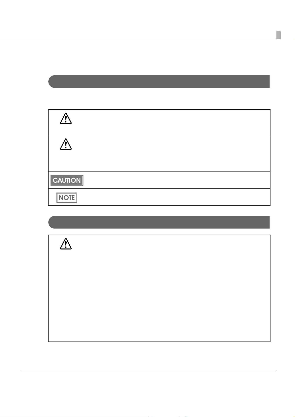
Part Names and Functions
For Multi Feed Models
Auto sheet feeder (ASF)
Main pocket
Sub pocket
Chapter 1 Product Overview
Document scanner
1
Scanner cover
Pocket guide
ASF guide
For Single Feed Models
Sheet feeder (SF)
Main pocket
Sub pocket*
Scanner cover open lever
Document scanner
Scanner cover
Scanner cover open lever
Pocket guide
SF guide
* The one pocket model does not have a Sub pocket.
13
Page 14
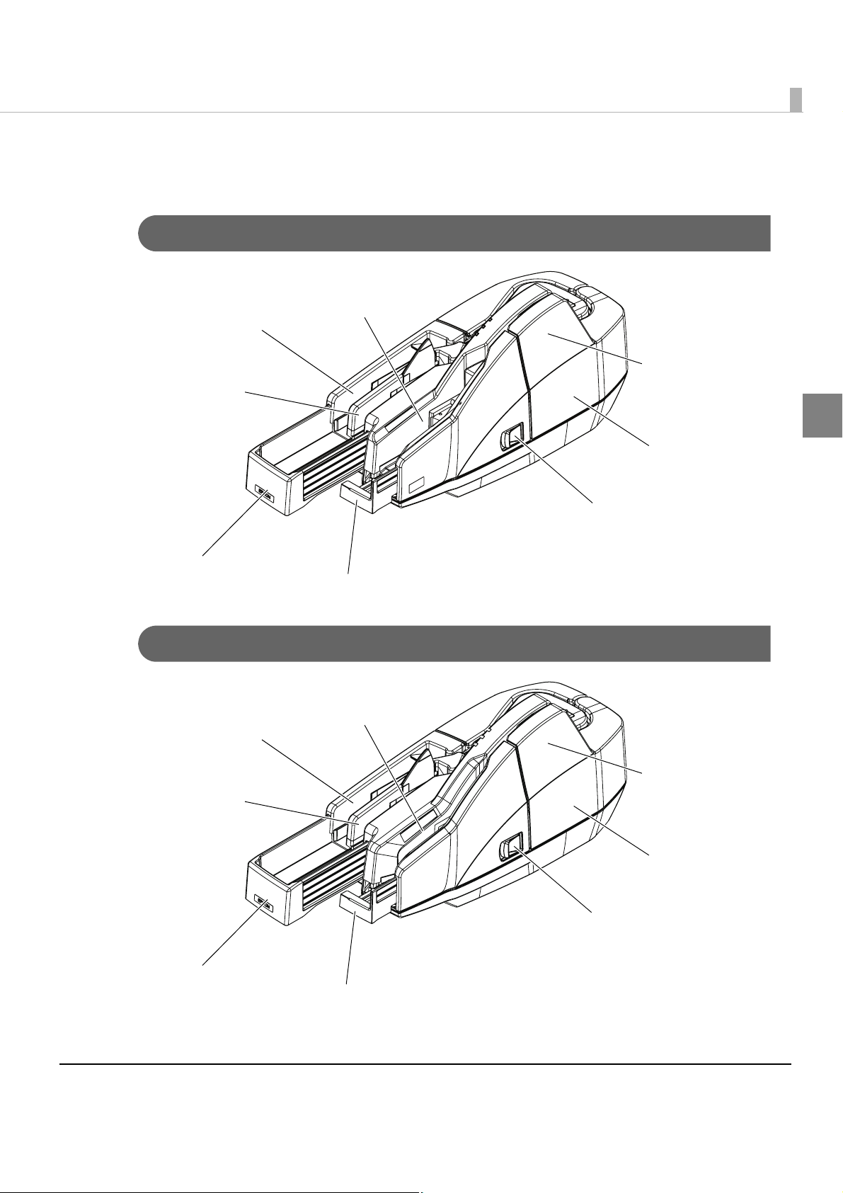
For All Models
Franker cover
Franker cover open lever
LED indicators
Power switch cover
Powe r swit ch
Power Switch
Turns the scanner on or off.
Before turning on the scanner, be sure to check that the AC adapter is connected to
the power supply.
CAUTION
Power Switch Cover
Install the power switch cover that comes with the TM-S1000 onto the scanner to prevent
inadvertent changing of the power switch, to prevent tampering, and to improve the appearance
of the scanner.
To re set the scanner when the power switch cover is installed, insert a long, thin object (such as
the end of a paper clip)
WARNING
into the hole in the power switch cover and press the power switch.
If an accident occurs with the power switch cover attached, unplug the power cord
immediately.
Continued use may cause fire or shock.
14
Page 15
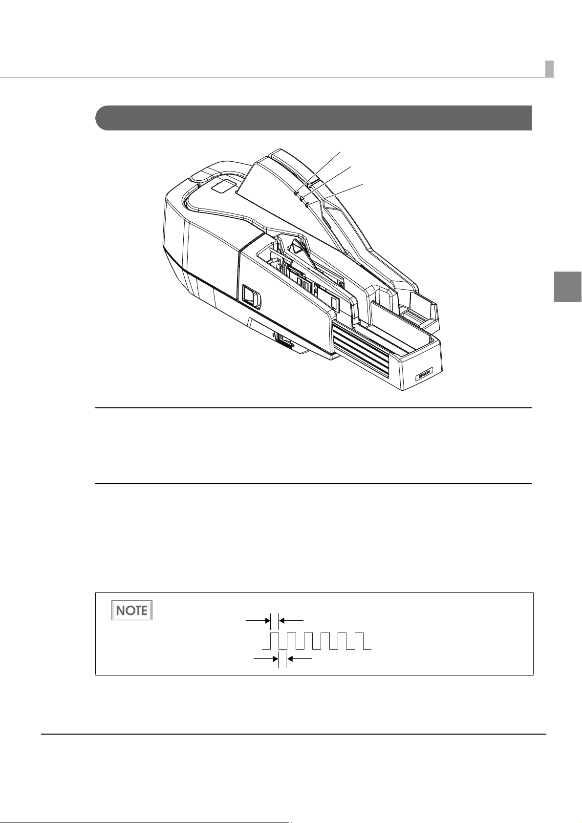
LED Indicators
Chapter 1 Product Overview
POWER LED
ERROR LED
DOCUMENT LED
1
POWER LED (Green)
•Lights when the power supply is on.
•Goes out when the power supply is turned off.
ERROR LED (Orange)
Lights or flashes when the scanner is offline.
•Lights after the power is turned on or after a reset (offline). Automatically goes out when the
scanner is ready.
•Flashes when an error occurs or when waiting for document removal. (For details about the
flash codes, see "Error Status" on page 27.)
When waiting for document removal, the ERROR LED flashes as shown below.
Approx.160 ms
Approx.160 ms
•Out during regular operation
(online).
15
Page 16

DOCUMENT LED (Green)
•Lights when the scanner is ready to process documents in the ASF/SF or while the scanner is
processing documents.
•Flashes when the scanner is waiting for document insertion.
When waiting for document removal, the ERROR LED flashes as shown below.
Approx.160 ms
Approx.160 ms
•Out except for the cases above.
Connectors
All cables are connected to the connector panel on the lower rear of the scanner.
USB cable securing hook
USB connector
•Power supply connector: Connects the power supply unit
•USB connector: Connects the scanner with the host computer interface.
•USB cable securing hook: Hooking the USB cable on the USB cable securing hook prevents
the cable from falling off.
Power supply connector
Offline
The scanner automatically goes offline under the following conditions:
•During power on (including resetting with the interface) until the scanner is ready
•When the scanner cover is opened.
•When the franker cover is opened.
•When an error has occurred.
16
Page 17

Chapter 1 Product Overview
Processing Modes
The TM-S1000 has multiple processing modes that are selectable in accordance with how you
want to use the scanner.
For detailed information about processing modes, see the TM-S1000 API Reference
Guide.
Multi feed models Single feed models
Processing
mode
High-speed
mode
Description
The scanner processes
a document without
stopping from feeding
a document until
ejecting it.
30 dpm
model
✔* ✔* ✔* ✔* ✔*
60 dpm
model
90 dpm
model
2 pckt
model
1 pckt
model
1
Confirmation
mode
w/o overlap
Confirmation
mode
with overlap
After reading a
document, the
scanner stops
processing before
ejecting it and waits
for a command from a
PC to restart
processing.
✔✔✔✔✔
✔✔
Without overlap: The next document is fed after a document is ejected into a pocket.
With overlap: The next document is fed while processing a document is still in progress.
*: Depending on the frank
ing/eject process setting, the scanner stops processing before ejecting
the document and restarts processing depending on the reading result. (For details, see
"Reading Operation" on page 21.)
17
Page 18

Processing speed
The processing speed (dpm: the number of documents that can be processed in 1 minute) for the
multi feed models when using the driver differ depending on the following conditions.
For 30 Dpm Model
High-speed
mode
Confirmation
Paper size
Personal check All disabled Regardless 30 dpm
Business check All disabled Regardless 30 dpm
Any check All disabled Regardless 28 dpm*
Driver/Application
settings*
One or more enabled Both disabled
One or more enabled Both disabled
1
Franking/Eject
Processing
process setting
Either or both enabled 28 dpm
Either or both enabled 28 dpm
mode
w/o overlap
One or more enabled Regardless
*1: Judgements of the following items can be enabled with the driver.
∗Magnetic waveform detection result
∗MICR “?” detection result
∗IQA result
Settings with an application are available only for the confirmation mode.
2
: The processing speed is a maximum. It may slow down depending on the environment
*
(including the application) and conditions of documents.
speed
2
18
The processing speed may slow down while saving data in the HDD.
Page 19

For 60 Dpm Model
Chapter 1 Product Overview
High-speed
mode
Confirmation
mode
with overlap
Confirmation
mode
w/o overlap
Paper size
Personal check All disabled Regardless 60 dpm
Business check All disabled Regardless 60 dpm
Any check All disabled Regardless 40 dpm*
Any check All disabled Regardless 28 dpm*
Driver/Application
settings*
One or more enabled Both disabled
One or more enabled Both disabled
One or more enabled Regardless 32 dpm*
One or more enabled Regardless
1
Franking/Eject
process setting
Either or both enabled 32 dpm
Either or both enabled 32 dpm
Processing
*1: Judgements of the following items can be enabled with the driver.
∗Magnetic waveform detection result
∗MICR “?” detection result
∗IQA result
Settings with an application are available only for the confirmation mode.
2
: The processing speed is a maximum. It may slow down depending on the environment
*
(including the application) and conditions of documents.
speed
2
2
2
1
The processing speed may slow down while saving data in the HDD.
19
Page 20

For 90 Dpm Model
High-speed
mode
Confirmation
Paper size
Personal check All disabled Regardless 90 dpm
Business check All disabled Regardless 75 dpm
Any check All disabled Regardless 40 dpm*
Driver/Application
settings*
One or more enabled Both disabled
One or more enabled Both disabled
1
Franking/Eject
Processing
process setting
Either or both enabled 32 dpm
Either or both enabled 32 dpm
mode
with overlap
Confirmation
Any check All disabled Regardless 28 dpm*
One or more enabled Regardless 32 dpm*
mode
w/o overlap
One or more enabled Regardless
*1: Judgements of the following items can be enabled with the driver.
∗Magnetic waveform detection result
∗MICR “?” detection result
∗IQA result
Settings with an application are available only for the confirmation mode.
2
: The processing speed is a maximum. It may slow down depending on the environment
*
(including the application) and conditions of documents.
speed
2
2
2
20
The processing speed may slow down while saving data in the HDD.
Page 21

Chapter 1 Product Overview
Reading Operation
The reading operation for the single feed models when using the driver differs depending on the
following conditions.
High-speed
mode
Confirmation
mode
w/o overlap
Driver/Application
settings*
All disabled Regardless The scanner processes a
One or more enabled Both disabled
All disabled Regardless After reading a document, the
One or more enabled Regardless
1
Franking/Eject
process setting
document without stopping
from feeding it until ejecting it.
Either or both enabled After reading a document, the
scanner stops processing
before ejecting it and restarts
processing depending on the
reading result.
scanner stops processing
before ejecting it and waits for
a command from a PC to
restart processing.
*1: Judgements of the following items can be enabled with the driver.
∗Magnetic waveform detection result
∗MICR “?” detection result
∗IQA result
Settings with an application are available only for the confirmation mode.
Reading operation
1
21
Page 22

Selectable processes
The following processes can be set with the application for both the multi feed models and single
feed models.
•Franking process
•With franking
•Without franking
•Ejection process
•Ejects documents to the Main pocket
•Ejects documents to the Sub pocket (except for the one pocket model)
•Does not eject documents
•Waterfall (except for the one pocket model)
• Electric endorse
•With electric endorse
•Without electric endorse
Each process is performed based on the parameters shown below.
High-speed mode Confirmation mode
Franking process
Ejection process
Electric endorse
• Double feeding detection result
• Incorrect insertion detection result
• External noise detection result
• Double feeding detection result
• Incorrect insertion detection result
• External noise detection result
• Double feeding detection result
• Incorrect insertion detection result
• External noise detection result
• Magnetic waveform detection result
• MICR “?” detection result
• IQA result
• If the waterfall function is enabled with the driver, the setting of the ejection process is
ignored. When the ejection pocket is near-full, the documents are automatically ejected
to the other pocket.
• The multi feed models detect a double feeding with the paper length sensor and paper
thickness sensor. The single feed models detect a double feeding only with the paper
length sensor when a more than 240 mm length document is detected in the paper path.
• Double feeding detection result
• Incorrect insertion detection result
• External noise detection result
• Magnetic waveform detection result
• MICR “?” detection result
• IQA result
• Double feeding detection result
• Incorrect insertion detection result
• External noise detection result
• Magnetic waveform detection result
• MICR “?” detection result
• IQA result
• Double feeding detection result
• Incorrect insertion detection result
• External noise detection result
• Magnetic waveform detection result
• MICR “?” detection result
• IQA result
22
Page 23

Chapter 1 Product Overview
Sensors
There are 7 paper sensors, 2 cover open sensors, and 5 other sensors. Some scanners are not
equipped with some of them depending on the model.
I
K
L
F
E
J
G
D
N
C
M
B
A
Note: The illustration shows the multi feed model.
H
Paper feed direction
Paper Sensors
ASF/SF sensor (A)
This sensor is located in the feeder paper path. It detects when a document is in the ASF/SF.
When the sensor detects a document, the DOCUMENT LED lights if scanning is possible.
Paper length sensor (B)
This sensor is located in the feeder paper path. It is mainly used for internal processing, but also
includes a function for detecting a piece of paper remaining in the feeder path in the event of a
paper jam or the like.
1
Middle sensor (C)
This sensor is located in the feeder paper path. It is mainly used for internal processing, but also
includes a function for detecting a piece of paper remaining in the feeder path in the event of a
paper jam or the like.
Franking sensor (D)
This sensor is located in the feeder paper path. It detects when a document has reached the
franking printing section.
23
Page 24

Eject sensor (E)
This sensor is located in the feeder paper path. It detects whether a document is properly ejected
and stored in a pocket.
Main pocket nearly full sensor (F)
This sensor is located in the Main pocket. It detects whether documents stored in the pocket need
to be removed.
• The sensor detects the nearly full status when the thickness of the documents in the
Main pocket exceeds the specified value (80 or more of documents whose thickness is
0.13 mm without folds, wrinkles, or roughness).
• To prevent paper jams, use the scanner in the driver mode that stops continuous
processing when a near-full pocket is detected. For detailed information about the driver
setting, see the TM-S1000 API Reference Guide.
Sub pocket nearly full sensor (G) (except for the one pocket model)
This sensor is located in the Sub pocket. It detects whether documents stored in the pocket need
to be removed.
• The sensor detects the nearly full status when the thickness of the documents in the Sub
pocket exceeds the specified value (40 or more of documents whose thickness is 0.13
mm without folds, wrinkles, or roughness).
• To prevent paper jams, use the scanner in the driver mode that stops continuous processing when a near-full pocket is detected. For detailed information about the driver
setting, see the TM-S1000 API Reference Guide.
Cover Open Sensors
Scanner cover open sensor (H)
This sensor detects the opening/closing of the scanner cover. The scanner automatically goes
offline when the cover is opened. It goes back online when the scanner cover is closed.
Franker cover open sensor (I)
This sensor detects the opening/closing of the franker cover. The scanner automatically goes
offline when the cover is opened. It goes back online when the franker cover is closed.
24
Page 25

Chapter 1 Product Overview
Other Sensors
Franking cartridge sensor (J)
This sensor detects whether the franking cartridge is installed or not.
Franking cartridge position sensor (K)
The franking cartridge is installed in the franking cartridge holder, and the franking operation is
achieved by a motor driving the cartridge holder. The scanner has a franking cartridge sensor for
detecting the position of the cartridge holder.
Pocket switch board sensor (L) (except for the one pocket model)
The scanner has two pockets, and a switch board for switching the direction of each of the
pockets. This sensor detects the position of the switch board.
1
Hopper position sensor (M)
This sensor is located in the ASF/SF. It detects the position of the hopper, which holds
documents in place.
Paper thickness sensor (N) (only for the multi feed models)
This sensor detects the level difference and thickness in order to determine whether or not paper
has been double fed.
Even if a double feed is detected, it is still possible to obtain MICR and image data that has
been read, and to carry out print electronic endorsements and franking.
25
Page 26

Maintenance Counter
The TM-S1000 has the maintenance counter to get the following counts.
Counter Counter type Unit
Reading count Resetable Number of times (1 ~ 4,294,967,295)
Cumulative Number of times (1 ~ 4,294,967,295)
Hopper open/close count Resetable Number of times (1 ~ 4,294,967,295)
Cumulative Number of times (1 ~ 4,294,967,295)
Franking drive count Resetable Number of times (1 ~ 4,294,967,295)
Cumulative Number of times (1 ~ 4,294,967,295)
Pocket switch count
(except for the one pocket model)
Product operation time Resetable Hour (1 ~ 71,582,788)
Resetable Number of times (1 ~ 4,294,967,295)
Cumulative Number of times (1 ~ 4,294,967,295)
Cumulative Hour (1 ~ 71,582,788)
•Reading count: Counts the number of documents read.
• Hopper open/close count: Counts the number of times that the hopper in the ASF/SF
switches from the closed state to the open state.
•Franking drive count: Counts the number of times that
the franker is driven.
•Pocket switch count: Counts the number of times that the direction is switched from
the Main pocket to the Sub pocket.
•Product operation time: Counts the number of hours that the power has been on.
26
Page 27

Chapter 1 Product Overview
Error Status
There are two possible error types: recoverable errors and unrecoverable errors.
Recoverable Errors
Processing is no longer possible when recoverable errors occur. They can be recovered easily by
turning the power off and then on again or sending an error recovery command from the driver
after eliminating the cause of the error.
Error LED flash code
Error Error description
Mechanism
position error
When any of the
following errors occurs
during the initialization
and operation.
• Error detected during
hopper position
detection operation.
• Error detected during
franker position
detection operation.
• Error detected during
pocket switch board
position detection
operation.
Approx.320 ms
Approx.5120ms
Recovery measure
1
Remove the cause
(foreign matter or
papers) and call
BiCancelError of the
TM-S1000 API or turn
off/on the power.
27
Page 28

Error Error description
Error LED flash code
Approx.320 ms
Approx.5120ms
Recovery measure
Paper jam error • After initialization,
paper detected
before the CIS.
• Paper jam.
(Paper length sensor,
middle sensor, franking
sensor, or ejection
sensors detected
paper feed error.)
• ASF/SF failed in feeding
paper.
• Too short/long paper
detected.
• Cover opened during
paper feeding.
Remove the paper
and call BiCancelError
of the TM-S1000 API or
turn off/on the power.
Remove the jammed
paper and call
BiCancelError of the
TM-S1000 API or turn
off/on the power.
Remove the paper left
in the paper path and
call BiCancelError of
the TM-S1000 API or
turn off/on the power.
If the paper is left in the
paper path, remove it
and call BiCancelError
of the TM-S1000 API
with covers closed or
turn off/on the power.
Reading error
(Only when the
scanner is set to
stop the
document at the
franking position
instead of
ejecting it into a
pocket if a
reading error
occurs.)
28
When any of the
following errors occurs in
the high-speed mode.
• A double feeding
detected.
• Other than “Check
was correctly inserted.”
detected.
• External noise
detected.
When an application
judges an error in the
confirmation mode.
The error recovery command is valid only if a recoverable error (excluding automatically
recoverable errors) occurs.
Open the franker
cover, remove the
paper, and call
BiCancelError of the
TM-S1000 API or turn
off/on the power.
Page 29

Chapter 1 Product Overview
Unrecoverable Errors
Processing is no longer possible when unrecoverable errors occur. The scanner must be repaired.
Turn off the power immediately when unrecoverable errors occur.
CAUTION
Error LED flash code
Error Error description
Memory R/W error After R/W checking, the scanner does not
work correctly.
High voltage error The power supply voltage is extremely
high.
Approx.320 ms
Approx.5120ms
1
Low voltage error The power supply voltage is extremely low.
CPU execution error The CPU is executing an incorrect address.
Internal circuit
connection error
Communication
device error
An image scanner sensor does not work
correctly.
A communication device does not work
correctly.
Compatibility with the TM-J9000/J9100
With a minimum modification of the application for the TM-J9000/J9100 (Epson ink-jet printers),
you can operate the TM-S1000 with a driver API for the TM-S1000.
For detailed information about the differences from the TM-J9000/J9100, see the API
Reference Guide.
29
Page 30

Product Specifications
Processing speed (only for the multi
feed models)
Operating
environment
(for satisfying
the processing
speed
specified)
CPU 30/60 dpm models without using IQA or single feed models:
Memory 30/60 dpm models without using IQA or single feed models:
HDD Free space of more than 30 MB (with the driver installed)
Operating
system
30 dpm, 60 dpm, or 90 dpm depending on the model.
At least a Pentium 4, 1.2 GHz or the equivalent
Multi feed models using IQA or 90 dpm model without using
IQA:
At least a Pentium 4, 2.0 GHz or the equivalent
At least 256 MB or above the minimum operating system
requirement
Multi feed models using IQA or 90 dpm model without using
IQA:
At least 512 MB or above the minimum operating system
requirement
Microsoft Windows 2000 Service Pack 4
Microsoft Windows XP 32 Bit Service Pack 2, Service Pack 3
Microsoft Windows Vista 32 bit Service Pack 1
Microsoft Windows Vista 64 bit Service Pack 1
.NET Framework .NET Framework 1.1, 2.0, 3.0, or 3.5
Interface USB 2.0 Hi-speed
Supported
development
languages
ASF/SF paper supply
(Number of sheets that can be
loaded)
MICR reader Reading
method
Supported fonts E13B, CMC7 (Alphabetic characters are not supported.)
OCR reader Supported fonts E13B
Electric endorsement • Different images can be pasted on each document.
Win32: Visual C++ 6.0, Visual Basic 6.0
.NET: Visual C++ .NET 2003, Visual C++ 2005, Visual C# .NET 2003,
Visual C# 2005, Visual Basic .NET 2003, Visual Basic 2005
ASF (for multi feed models): 100 sheets or fewer
SF (for single feed models): one sheet
Permanent magnetic bias
OCR A, OCR B
• More than one image can be pasted.
• Logos, graphics, and TrueType fonts are available.
30
Page 31

Chapter 1 Product Overview
Pocket storage Main pocket 100 sheets or fewer (when the paper thickness is 0.13 mm or
less). However, the total thickness must be 13 mm or less
including warps.
Sub pocket
(Except for the
one pocket
model)
Franking
cartridge
Supply voltage DC24 V ± 10%
Interface USB 2.0
Reliability Life 1,000,000 sheets
Type Exclusive franking cartridge (EFC-01)
Ink color Red
Life of ink 18,000 times (based on Epson’s standard pattern used for
MTBF 180,000 hours (A failure is defined as a random failure occurring
MCBF 2,470,000 cycles (An overall average failure interval based on
50 sheets or fewer (when the paper thickness is 0.13 mm or
less). However, the total thickness must be 6.5 mm or less
including warps.
printing)
during the random failure period)
failures relating to wear out and random failures up to the
lifespan of 1,000,000 transactions.) and random failures up to
the lifespan of 1,000,000 transactions.)
1
Overall dimension (W × H × D) 355 × 176 × 160 mm {14.0 × 6.93 × 6.30 in}
Mass (approx.) Multi feed models: Approximately 4.0 kg {8.82 lb}
Single feed models: Approximately 3.9 kg {8.60 lb}
dpm: documents per minute, dpi: dots per inch (25.4 mm)
31
Page 32

Scanner Specifications
Image Scanner CIS (Contact Image Sensor)
Resolution 200 × 200 dpi, 120 × 120 dpi, 100 × 100 dpi
Graduation 256-level gray scale, 2 values (Black and White)
Data compression
format
Data format Gray scale TIFF, JPEG, BMP, Raster
Scanning area (W × H) 100* (*fixed) × max. 235 mm {3.94* (*fixed) × max. 9.25 in}
Image quality Complies with IQA (Image Quality Assurance) formulated
Deskew Deskews the image on the skewing document, according
Auto size adjustment Crops the image and adjusts the size to the document
Scanning speed 500 mm/s {19.69 in/s}
Gray scale JPEG
Black and White CCITT/group 4
Black and White*
1
TIFF*2, BMP
by FSTC (Financial Services Technology Consortium).
to the TM-S1000 driver settings.
size, according to the TM-S1000 driver settings.
dpi: dots per inch (25.4 mm)
1
: Image noises are eliminated automatically when the TM-S1000 driver digitizes grayscale
*
images.
2
: The TIFF format of resolution 200 dpi, binary, CCITT-Group 4 compression conforms to ANSI
*
X9.100-181-2007.
32
Page 33

Chapter 1 Product Overview
Paper Specifications
Type Normal paper (single-ply only)
Size (H × L) 68 ∼ 120 mm {2.68 ~ 4.72 in} × 120 ∼ 235 mm {4.72 ~ 9.25 in}
Thickness 0.075 ∼ 0.2 mm {0.003 ∼ 0.008 in} (single-ply only)
Weight 60 ∼ 120 g/m
• Make sure that the paper has no curl, folds (especially at the top edges), warps, or
wrinkles. Otherwise a paper jam may occur.
• Since the paper sensors use a translucent photo sensor and reflective photo sensor, do
not use paper that has holes or translucency at the sensor position as shown in the figures below.
For multi feed models
<Front>
45
35
<Back>
45
35
2
{16 ∼ 32 lb}
1
Area where holes and
translucency are prohibited.
Area where holes are
prohibited and the reflection
rate of the paper surface
must be 40% or more.
30
15
For single feed models
45
35
45
35
17
7
<Front>
17
7
<Back>
30
15
[Units: mm]
33
Page 34

• The paper sensors ignore the range indicated in the figure below for the guide holes in
fan-folded paper.
Diameter: 6 mm or less
Scannable Area
Image scanning may not be possible in the area a, b, and c in the figures below.
Image length: Max.269.5
No. 12345
pay to
the order of
Front>
<
$
Image height: Max.102.6
Dollars
b=10.0
MICR character
c=3.0
Paper inserting direction
a=10.0b=10.0
Image length: Max.269.5
<Back>
Image height: Max.102.6
c=3.0
Paper inserting direction
a=10.0
[Units: mm]
Note: Values are typical.
34
Page 35

MICR Readable Area
MICR readable paper length: Max.235
Chapter 1 Product Overview
(10.0)
MICR readable length: Max.225
(222.25 [maximum length of check paper] + 2.75)
Area for Electric Endorsement
120 ~ 235
<Front or Back>
Max. 8.0
Max. 12.25
[Units: mm]
1
68~ 100
[Units: mm]
Area for Franking
76
25
7.7
25.5
[Units: mm]
35
Page 36

Electrical Characteristics
Power supply AC adapter, C
Operating voltage 24 V ± 10%
Current
consumption
Operating Mean: Approximately 1.0A
Standby Mean: Approximately 0.2A
Environmental Conditions
Temperature/
humidity
Operating 10 ~ 40°C {50 ~ 104°F}, 20 ~ 80% RH without condensation
Storage
(Factory packing)
Maximum
absolute rated
temperature
(See the operating temperature and humidity range below.)
-20 ~ 60°C {-4 ~ 140°F}, 5 ~ 85% RH without condensation (120
hours or less at -20 {-4°F} or 60°C {140°F})
70°C {158°F} (This temperature must never be exceeded
during operation or storage.)
[%RH]
80
55
36
Humidity (%)
20
10 27 35 40
Temperature ( )
°C
Page 37
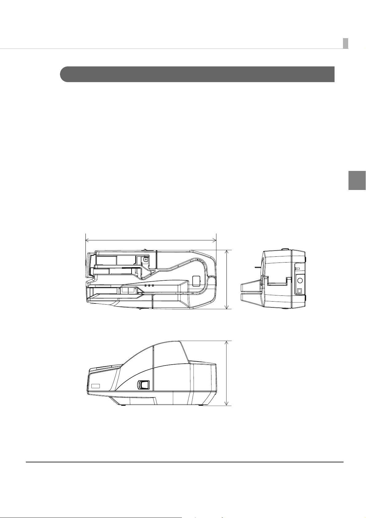
External Dimensions and Mass
Height
Approximately 176 mm {6.93 in}
Width
Approximately 355 mm {13.98 in}
Depth
Approximately 160 mm {6.30 in}
Chapter 1 Product Overview
Mass
Multi feed models: Approximately 4.0 kg {8.82 lb}
Single feed models: Approximately 3.9 kg {8.60 lb}
355
1
160
176
[Unit: mm]
Note: The illustrations show the multi feed model.
37
Page 38

38
Page 39
Setup
This chapter describes setup and installation of the product.
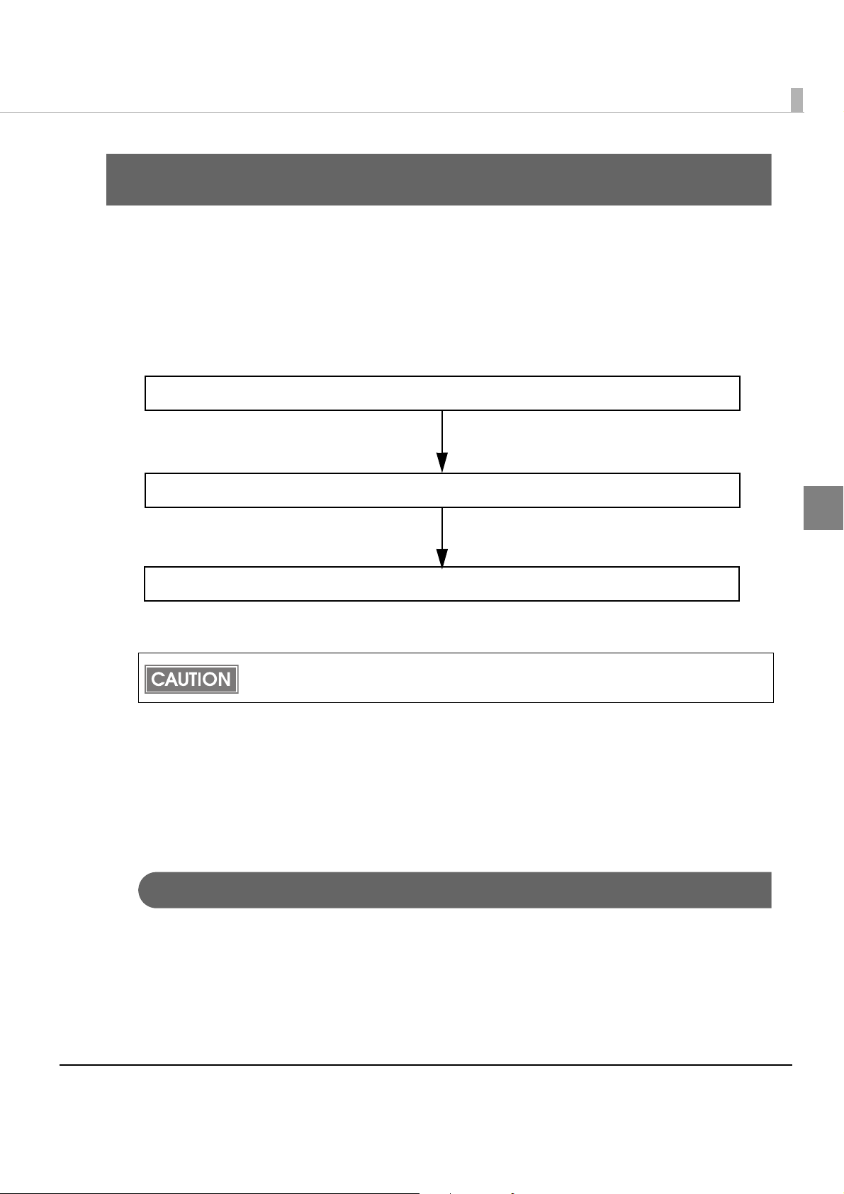
Flow of Setup
This chapter consists of the following sections along with the setup flow of the product.
1. Installing the Scanner (page 39)
2. Connecting the Scanner to the Host Computer (page 40)
Chapter 2 Setup
3. Connecting the Power Supply Unit (page 41)
Do not change the settings of the DIP switch under the bottom cover.
Installing the Scanner
Yo u can install this scanner only horizontally.
Important Notes on Installation
2
•The scanner must be installed horizontally.
•Do not place the scanner in dusty locations.
•Do not catch cables or allow foreign matter under the scanner.
•Do not subject the scanner to abnormal impact while it is operating. This may cause defective
readings.
39
Page 40

Connecting the Scanner to the Host Computer
Connect the scanner to a host computer via a USB port.
Start the TM-S1000 Utility included on the Utility & Documents CD.
1
Starting the TM-S1000 Utility causes the USB driver to be installed. Be sure to start the
TM-S1000 Utility before connecting the scanner to a host computer.
If the scanner is connected to a host computer before installing the USB driver, the Found
New Hardware Wizard will be displayed. In that case, cancel the wizard and start the
TM-S1000 Utility to install the USB driver.
When the TM-S1000 Utility has started, connect the USB cable from the
2
host computer to the USB upstream connector.
• Be sure to use the USB cable that is included with the scanner.
• Hook the USB cable on the USB cable securing hook as shown in the figure below to
prevent the cable from falling off.
USB cable
USB cable securing hook
USB connector
40
Page 41

Connecting the Power Supply Unit
Use the AC adapter. C as the power supply unit.
• Always use the AC adapter. C as the power supply unit.
Using a nonstandard power supply can result in electric shock and fire.
WARNING
Make sure the scanner’s power supply is turned off and the power supply
1
unit’s power cable has been removed from the wall socket.
Insert the connector of the power supply cable onto the power supply
2
connector (stamped 24V).
• Should a fault ever occur in the Epson AC adapter. C, immediately turn off the
power to the scanner and remove the power supply cable from the wall socket.
Chapter 2 Setup
Power supply cable
CAUTION
2
Power supply connector
• Be sure to remove the power supply unit’s cable from the wall socket whenever
connecting or disconnecting the power supply unit to the scanner.
Failure to do so may result in damage to the power supply unit or the scanner.
• Make sure the wall socket power supply satisfies the rated voltage requirements
of the power supply unit. Never insert the power supply cable plug into a socket
that does not meet the rated voltage requirements of the power supply unit.
Doing so may result in damage to both the power supply and the scanner.
Before removing the DC cable connector from the AC adapter. C, make sure the power
supply cable has been removed from the power supply unit; then grasp the arrow-marked
section of the connector and pull straight out.
41
Page 42

42
Page 43

Chapter 3 Application Development Information
Application Development Information
This chapter gives information useful for scanner application development.
Software and Manuals
The following software and manuals are provided for application development.
Software Description Manual
TM-S1000 API This API controls various functions of
the TM-S1000. Log files of API used
by applications are helpful for
troubleshooting. A silent installation
is also available. Sample programs
are provided.
TM-S1000 Utility Use to obtain internal information
about the scanner and for
maintenance.
The TM-S1000 Utility and the TM-S1000 Utility User’s Manual are included on the Utility &
Documents CD that is included with the scanner.
TM-S1000 API Reference Guide
TM-S1000 .NET API Reference Guide
TM-S1000 Utility User’s Manual
Download
Software and manuals can be downloaded from one of the following URLs.
For customers in North America, go to the following web site:
http://www.epsonexpert.com/ and follow the on-screen instructions.
For customers in other countries, go to the following web site:
3
http://www.epson-pos.com/
43
Page 44

TM-S1000 Utility
The TM-S1000 Utility is provided for analyzing the scanner and troubleshooting.
With the TM-S1000 Utility, y o u can check the operation of the scanner, confirm the scanner
status, and perform MICR cleaning.
For more information about the TM-S1000 Utility, see the TM-S1000 Utility User’s manual.
Functions of the Utility
Yo u can use the following functions by running the TM-S1000 Utility.
Obtaining information
•Get the internal information of the TM-S1000
∗ Firmware version
∗ Product serial number
∗ Process speed (30/60/90 dpm)
∗ Remote wakeup enabled/disabled
∗ Franker installed/not installed
∗ Number of pockets
∗ Model type
∗ Waterfall supported/not supported
•Get the USB descriptor (specification of a USB device) of the device
•Get the host PC information
∗ OS version/language
∗ TM-S1000 driver version
∗ Installed .NET Framework
∗ USB driver stack
∗ CPU and memory information
Save/Reading obtained information
•Save the obtained values in a file
•Read the obtained values from a file
Operation check
•Scan and check the MICR character data
•Scan and check the photo data
•Check the paper feed test
Clean the MICR unit
44
Page 45
Handling
This chapter describes basic handling of the scanner.
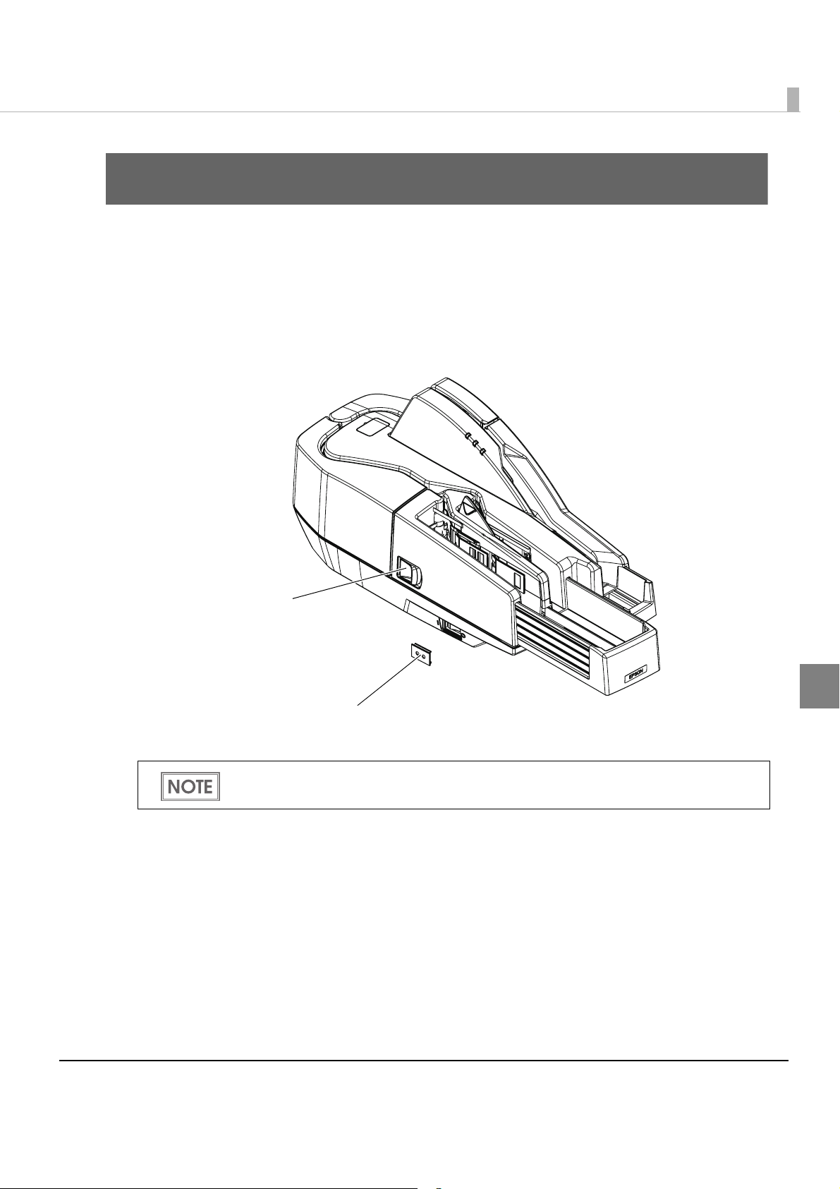
Turning On/Off
Press the power switch to turn the scanner on or off.
Chapter 1 Handling
Power sw i tch
If the power switch cover is attached over the power switch, insert a pointed object into one
of the holes of the cover to press the switch.
4
Power switch cover
45
Page 46

Opening the Covers
Do not open the covers during processing. Otherwise a scanning error, a MICR error, or a
paper jam may result.
Opening the Scanner Cover
Pull the scanner cover open lever to open the scanner cover.
Open the scanner cover when you clean the glass of the scanner (See "Cleaning the Image
Scanner" on page 55.) or remove jammed paper. (See "Removing a Paper Jam" on page 57.)
Do not touch the glass areas of the scanner inside the scanner cover with your bare hands.
Glass area of scanner
Scanner cover open lever
46
Page 47
Chapter 1 Handling
Opening the Franker Cover
Pull the franker cover open lever to open the franker lever.
Open the franker cover when you replace the franking cartridge with new one (See "Installing
and Replacing the Franking Cartridge" on page 48.) or remove jammed paper. (See "Removing a
Paper Jam" on page 57.)
Franker cover open lever
4
47
Page 48

Franking Cartridge
Important Notes on the Franking Cartridge
•Keep the franking cartridges out of the reach of children.
•Do not disassemble franking cartridges.
•Be careful during handling because the ink can permanently stain clothing.
•Seiko Epson recommends using genuine Epson cartridges for your scanner. Products of ot
manufacturers may adversely affect the scanner and printing quality, and may result in the
scanner not being able to achieve the specified performance levels.
•Do not remove the franking cartridge from the packing box until immediately before its
installation. Leaving the cartridge out
adversely affect printing quality.
•Use up the franking cartridge within 18 months from the date of production indicated on the
cartridge box.
•Dispose of the franking cartridge in accordance with any relevant national or local laws,
ances, and regulations.
ordin
of its packing for a prolonged period of time may
her
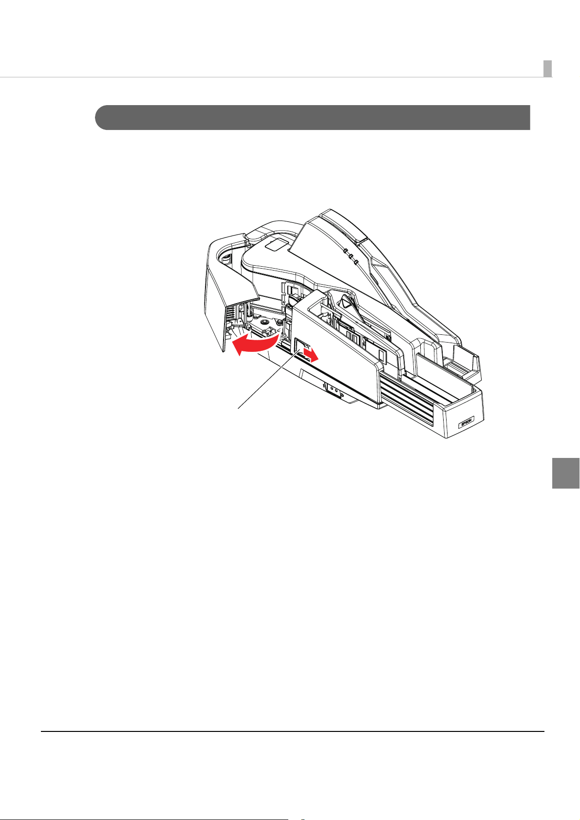
Installing and Replacing the Franking Cartridge
Follow these steps to install a franking cartridge for the first time or to replace it.
Open the franker cover.
1
(See "Opening the Franker Cover" on page 47.)
48
If a used franking cartridge is installed, hold the knob at the top of the
2
cartridge and lift the cartridge out of the scanner.
Franking cartridge
Page 49

Chapter 1 Handling
Carefully insert a new franking cartridge from the top, and push it firmly
3
but gently until it clicks in place.
Close the franker cover firmly until it clicks in place.
4
49
4
Page 50

Pulling Out the Guides
Pocket guide
ASF/SF guide
Pocket Guide
Be sure to pull out the pocket guide far enough to accommodate the documents stored in
the guide before using the scanner. Otherwise a paper jam may occur.
ASF/SF Guide
Feeding paper using the ASF/SF guide allows you to insert documents straight. Pull out the
ASF/SF guide if necessary.
50
Page 51

Chapter 1 Handling
Processing Documents
The TM-S1000 is capable of performing the following four actions on a document in a single
pass: scanning the image of both the face and the back, reading magnetic characters, and
franking.
Flow of Single Pass Processing
4
3
2
5
1
Insert a document into the feeder section. (See "Inserting Checks" on page 52.)
1
The scanner scans the images of the face and back.
2
The scanner reads the magnetic characters on the document.
3
The franking section prints a pattern.
4
The document is fed to the outlet. (See "Ejecting Checks" on page 54.)
5
Important Notes on Processing Documents
• Use paper that meets the scanner specification. (See "Paper Specifications" on page 33.)
•Do not use copy paper or other multi-ply paper.
4
•Make sure that the documents have no curl, bending (especially on the corners), warpage, or
wrinkles.
•Do not use checks with paper clips, staples, adhesive tape, or other foreign materials attached.
•Do not open the covers while processing is in progress.
51
Page 52

Inserting Checks
For the multi feed models, you can put up to 100 documents in the ASF to be fed automatically.
For the single feed models, put documents in the SF one by one to be fed automatically.
For multi feed models
Align the documents neatly on the bottom-right corner as shown in the
1
picture below so that they will be fed one by one.
If the documents are inserted without being aligned, they may not be fed at all, or a paper
jam or incorrect feeding of multiple documents may result.
1234780 1234567890
Insert documents straight with their faces (the side on which magnetic
2
characters are printed) facing outside into the ASF, as shown in the
picture below.
• Be sure to let go of the documents before the scanner starts feeding. Otherwise, there
may be a paper skew, paper jam, or MICR reading error.
• Do not open the covers while processing is in progress.
1234780 1234567890
52
Page 53

Chapter 1 Handling
For single feed models
Insert a document straight with its face (the side on which magnetic
1
characters are printed) facing outside into the SF, as shown in the picture
below.
• Do not put more than one document in the SF. Otherwise, a paper jam or incorrect feeding of multiple documents may result.
• Be sure to let go of the document before the scanner starts feeding. Otherwise, there
may be a paper skew, paper jam, or MICR reading error.
• Do not open the covers while processing is in progress.
1234780 1234567890
After the document is automatically ejected to the Main/Sub pocket,
2
put the next document into the SF.
1234780 1234567890
4
53
Page 54

Ejecting Checks
When the documents are ejected, remove the documents.
Do not leave more than the specified number of documents in the pockets while processing
documents (Main pocket: 100 sheets, sub pocket: 50 sheets). Otherwise, a paper jam may
occur.
Sub pocket
Main pocket
• Some documents may be ejected into the sub pocket depending on your application.
(Except for the one pocket model)
• Buzzer may sound to notify errors depending on your application.
54
Page 55

Chapter 1 Handling
Cleaning
Cleaning the Image Scanner
If the glass of the scanner gets soiled from ink or paper dust, the quality of the image data may
deteriorate. Clean the glass every 6 months or every 100,000 passes.
Follow these steps to clean the glass.
Open the scanner cover.
1
(See "Opening the Scanner Cover" on page 46.)
Lightly wipe the glass areas shown in the picture below with a soft, dry
2
cloth.
When the glass of the scanner is smeared with oil, grease or other
unremovable substance, wipe it with a cloth lightly dipped in alcohol.
CAUTION
• Do not use synthetic detergent, benzine, water, or other liquid for cleaning.
Doing so may result in a stain.
• Never apply any liquid directly to the glass of the scanner.
4
Close the scanner cover firmly until it clicks in place.
3
It is recommended to clean the image scanner once per week or once every 2,000 checks
for good reading results.
55
Page 56

Cleaning the MICR Unit
Dirt on the MICR unit may cause frequent magnetic character reading errors. Clean the MICR
unit every 6 months or every 100,000 passes.
Use the self-test tool in the CD-ROM included with the scanner or your application to clean the
MICR unit.
Use KIC Products "Waffletechnology cleaning card (Part No. KW2663-CS1B15WS EPSON
CAPTURE ONE WAFFLE WS CLEANING CARDS 15/BOX)."
• Do not use sticky cleaning sheets.
They may cause a paper jam or machine failure.
CAUTION
• Be sure to dispose of used cleaning sheets.
• For detailed information on cleaning procedures, see the manuals for the self-test tool or
your application.
• It is recommended to clean the MICR unit once per week or once every 2,000 checks for
good reading results.
• It is recommended to clean the image scanner after cleaning the MICR unit. (See
"Cleaning the Image Scanner" on page 55.)
56
Page 57

Removing a Paper Jam
Open the scanner cover or franker cover to remove the jammed paper. (See "Opening the
Scanner Cover" on page 46 and "Opening the Franker Cover" on page 47.)
Preparing for Transport
Follow the steps below to transport the scanner.
Turn off the scanner.
1
Confirm that POWER LED is off.
2
Remove the power supply connector.
3
Chapter 1 Handling
Store the pocket guide and the ASF/SF guide inside the scanner.
4
Pack the scanner upright.
5
4
57
Page 58

58
 Loading...