

Page 1
Technical Reference Guide
Describes features of the product.
Describes how to mount a tablet/display to the printer.
Describes setup and installation of the product and
peripherals.
Describes how to install and use optional products
dedicated for this product.
Describes advanced usage methods for the product.
Describes how to control the printer and necessary
information when you develop applications.
Describes how to handle the product.
Describes general specications and character code
tables.
Product Overview
Setup of the Tablet
Setup of the Printer
Using Dedicated Optional Products
Advanced Usage
Application Development Information
Handling
Appendix
M00135900
Rev. A
Page 2

Cautions
• No part of this document may be reproduced, stored in a retrieval system, or transmitted in any form or by
any means, electronic, mechanical, photocopying, recording, or otherwise, without the prior written
permission of Seiko Epson Corporation.
• The contents of this document are subject to change without notice. Please contact us for the latest
information.
• While every precaution has been taken in the preparation of this document, Seiko Epson Corporation
assumes no responsibility for errors or omissions.
• Neither is any liability assumed for damages resulting from the use of the information contained herein.
• Neither Seiko Epson Corporation nor its affiliates shall be liable to the purchaser of this product or third
parties for damages, losses, costs, or expenses incurred by the purchaser or third parties as a result of:
accident, misuse, or abuse of this product or unauthorized modifications, repairs, or alterations to this
product, or (excluding the U.S.) failure to strictly comply with Seiko Epson Corporation’s operating and
maintenance instructions.
• Seiko Epson Corporation shall not be liable against any damages or problems arising from the use of any
options or any consumable products other than those designated as Original Epson Products or Epson
Approved Products by Seiko Epson Corporation.
Trademarks
EPSON is a registered trademark of Seiko Epson Corporation.
Exceed Your Vision and ESC/POS are registered trademarks or trademarks of Seiko Epson Corporation.
Microsoft and Windows are registered trademarks of Microsoft Corporation in the United States and/or other
countries.
Wi-Fi
®, WPA
The Bluetooth
such marks by Seiko Epson Corporation is under license.
IOS is a trademark or registered trademark of Cisco in the U.S. and other countries and is used under license.
Apple, Apple TV, Apple Watch, iPad, iPad Air, iPad Pro, iPhone, and Lightning are trademarks of Apple Inc.,
registered in the U.S. and other countries. tvOS is a trademark of Apple Inc. The trademark "iPhone" is used in
Japan with a license from Aiphone K.K.
Android
Google Play and the Google Play logo are trademarks of Google LLC.
All other trademarks are the property of their respective owners and used for identification purpose only.
TM
, and WPA2TM are either registered trademarks or trademarks of Wi-Fi Alliance®.
® word mark and logos are registered trademarks owned by Bluetooth SIG, Inc. and any use of
TM
is a trademark of Google LLC.
ESC/POS® Command System
Epson ESC/POS is a proprietary POS printer command system that includes patented or patent-pending
commands. ESC/POS is compatible with most Epson POS printers and displays.
ESC/POS is designed to reduce the processing load on the host computer in POS environments. It comprises a
set of highly functional and efficient commands and also offers the flexibility to easily make future upgrades.
©Seiko Epson Corporation 2021.
Page 3
For Safety
Key to Symbols
The symbols in this manual are identified by their level of importance, as defined below. Read the following
carefully before handling the product.
You must follow warnings carefully to avoid serious bodily injury.
WARNING
Provides information that must be observed to prevent damage to the equipment or loss of data.
• Possibility of sustaining physical injuries.
CAUTION
• Possibility of causing physical damage.
• Possibility of causing information loss.
Provides information that must be observed to avoid damage to your equipment or a malfunction.
Provides important information and useful tips.
Warnings
WARNING
• Handle the power cable with care.
Improper handling may lead to fire or electric shock.
∗ Do not modify or attempt to repair the cable.
∗ Do not place any heavy object on top of the cable.
∗ Avoid excessive bending, twisting, and pulling.
∗ Do not place the cable near heating equipment.
∗ Check that the plug is clean before plugging it in.
∗ Be sure to push the plug all the way in.
• Be sure to use the specified AC adapter (PS-180).
Connection to an improper power source may cause fire or shock.
• Do not place multiple loads on the power outlet.
Overloading the outlet may lead to fire.
• Shut down your equipment immediately if it produces smoke, a strange odor, or unusual
noise.
Continued use may lead to fire. Immediately unplug the equipment and contact qualified
service personnel.
• Never disassemble or modify this product.
Tampering with this product may result in injury or fire.
• Do not allow foreign matter to fall into the equipment.
Penetration by foreign objects may lead to fire.
• If water or other liquid spills into this equipment, do not continue to use it.
Continued use may lead to fire. Unplug the power cord immediately and contact qualified
service personnel.
• Do not use aerosol sprayers containing flammable gas inside or around this product.
Doing so may cause fire.
• Do not use this product in locations subject to high humidity or dust levels.
Excessive humidity and dust may cause equipment damage or fire.
3
Page 4

Cautions
CAUTION
• Do not connect cables in ways other than those mentioned in this manual.
Different connections may cause equipment damage.
• Be sure to set this equipment on a firm, stable, horizontal surface.
The product may break or cause injury if it falls.
• Do not place heavy objects on top of this product. Never stand or lean on this product.
Equipment may fall or collapse, causing breakage and possible injury.
• Take care not to injure your fingers on the manual cutter
∗ When you remove printed paper
∗ When you perform other operations such as loading/replacing roll paper
• Do not open the roll paper cover without taking the necessary precautions, as this can
result in injury from the autocutter fixed blade.
• To ensure safety, unplug this product before leaving it unused for an extended period.
• To avoid risk of electric shock, do not set up this product or handle cables during a
thunderstorm.
• Never insert or disconnect the power plug with wet hands.
Doing so may result in severe shock.
• Never attempt to repair this product yourself.
Improper repair work can be dangerous.
4
Page 5

Restriction of Use
When this product is used for applications requiring high reliability/safety, such as transportation devices
related to aviation, rail, marine, automotive, etc.; disaster prevention devices; various safety devices, etc.; or
functional/precision devices, etc., you should use this product only after giving consideration to including failsafes and redundancies into your design to maintain safety and total system reliability. Because this product was
not intended for use in applications requiring extremely high reliability/safety, such as aerospace equipment,
main communication equipment, nuclear power control equipment, or medical equipment related to direct
medical care, etc., please make your own judgment on this product's suitability after a full evaluation.
Note about interference
• This product generates, uses, and can radiate radio frequency energy and, if not installed and used in
accordance with the instruction manual, may cause harmful interference to radio communications.
• If this equipment does cause harmful interference to radio or television reception, which can be determined
by turning the equipment off and on, the user is encouraged to try to correct the interference by one or more
of the following measures:
- Reorient or relocate the receiving antenna for the radio/TV.
- Increase the separation between the equipment and the radio/TV.
- Connect the equipment into an outlet on a circuit different from that to which the receiver is connected.
- Consult your dealer or an experienced radio/TV technician for help.
• Never disassemble or modify this product.
• Seiko Epson Corporation shall not be liable for interference to radio/TV resulting from changes or
modifications to this product not expressly approved by Seiko Epson Corporation.
Open Source Software License
This product uses open source software in addition to Epson proprietary software.
For information of the open source software used in this product, see the following URL.
http://xxx.xxx.xxx.xxx/licenses.html
For “xxx.xxx.xxx.xxx” in the above URL, input your printer’s IP address.
5
Page 6

About this Manual
Aim of the Manual
This manual was created to provide information on development, design, and installation of POS systems and
development and design of printer applications for developers.
Manual Content
The manual is made up of the following sections:
Chapter 1 Product Overview
Chapter 2 Setup of the Tablet
Chapter 3 Setup of the Printer
Chapter 4 Using Dedicated Optional Products
Chapter 5 Advanced Usage
Chapter 6 Application Development Information
Chapter 7 Handling
Appendix Product Specifications
Specifications of
Bluetooth Low Energy Technology Advertising
Character Code Tables
Compatibility with USB Type-A
Interface and Connector
6
Page 7

Contents
■ For Safety..................................................................................................................................3
Key to Symbols.................................................................................................................................................................. 3
Warnings ............................................................................................................................................................................. 3
Cautions............................................................................................................................................................................... 4
■ Restriction of Use ....................................................................................................................5
■ Note about interference ........................................................................................................5
■ Open Source Software License.............................................................................................5
■ About this Manual ..................................................................................................................6
Aim of the Manual ........................................................................................................................................................... 6
Manual Content ................................................................................................................................................................ 6
■ Contents....................................................................................................................................7
Product Overview ..........................................................................................12
■ Features ................................................................................................................................. 12
■ Product Configurations ...................................................................................................... 14
Accessories .......................................................................................................................................................................14
Options ..............................................................................................................................................................................14
■ Part Names and Functions ................................................................................................. 15
Front....................................................................................................................................................................................15
Bottom ...............................................................................................................................................................................16
Panel LED ..........................................................................................................................................................................17
Connectors .......................................................................................................................................................................18
Online and Offline..........................................................................................................................................................20
■ Status and Errors .................................................................................................................. 21
Status Display ..................................................................................................................................................................21
Bluetooth Connection Status ....................................................................................................................................22
Network Connection Status .......................................................................................................................................23
Error Status .......................................................................................................................................................................24
■ NV Memory (Non-Volatile Memory) ................................................................................. 25
NV Graphics Memory....................................................................................................................................................25
User NV Memory ............................................................................................................................................................25
Memory Switches (customized values)..................................................................................................................25
R/E (Receipt Enhancement) ........................................................................................................................................25
Maintenance Counter...................................................................................................................................................26
■ Simple Setup for Wireless LAN .......................................................................................... 27
■ Useful Functions for Smart Devices.................................................................................. 28
QR Code.............................................................................................................................................................................28
■ Printing Using Multiple Interfaces.................................................................................... 29
7
Page 8

Setup of the Tablet......................................................................................... 30
■ Flow of Setup ........................................................................................................................ 30
■ Tablets that Can be Mounted to the Printer ................................................................... 31
■ Front Tablet ........................................................................................................................... 32
Mountable Tablet Sizes ................................................................................................................................................32
Mountable Tablet Types...............................................................................................................................................33
■ Rear Display .......................................................................................................................... 34
■ Preparation for Setup.......................................................................................................... 35
Preparation of Tablet.....................................................................................................................................................35
Routing the Cables ........................................................................................................................................................35
■ Mounting the Front Tablet ................................................................................................. 36
■ Connecting Peripheral Devices ......................................................................................... 41
■ Connecting the AC Cable.................................................................................................... 42
■ Attaching the Lock Lever Cover ........................................................................................ 45
■ Replacing the Tablet Table ................................................................................................. 46
Setup of the Printer........................................................................................ 48
■ Flow of Setup ........................................................................................................................ 48
■ Placing the Printer ............................................................................................................... 49
Placing the Printer Horizontally ................................................................................................................................49
Placing the Printer Vertically ......................................................................................................................................50
■ Changing the Paper Width ................................................................................................. 52
■ Connecting Peripheral Devices ......................................................................................... 53
■ Connecting the Wireless LAN Unit.................................................................................... 58
■ Connecting the Customer Display.................................................................................... 59
■ Connecting the Optional External Buzzer....................................................................... 60
Attachment Position .....................................................................................................................................................60
■ Connecting the Cash Drawer............................................................................................. 61
Required specifications of cash drawers................................................................................................................61
Connecting the drawer kick cable ...........................................................................................................................62
■ Connecting to the Power Source ...................................................................................... 63
Connecting the AC cable.............................................................................................................................................63
■ Connecting the Printer to the Host Devices.................................................................... 64
USB Interface ...................................................................................................................................................................64
Ethernet Interface ..........................................................................................................................................................64
Wireless LAN Interface (When using OT-WL02/OT-WL05/OT-WL06)...........................................................64
Bluetooth Interface .......................................................................................................................................................67
■ Attaching the Power Switch Cover ................................................................................... 70
8
Page 9

■ Enabling the Roll Paper Near-End Detection.................................................................. 71
Using Dedicated Optional Products ............................................................ 72
■ OT-DM30SL (Customer Display) ........................................................................................ 72
Mounting OT-DM30SL..................................................................................................................................................72
Adjusting the Display Brightness .............................................................................................................................76
Cleaning the Outer Case..............................................................................................................................................76
Product Specifications..................................................................................................................................................76
WARNING ..........................................................................................................................................................................77
Restriction of Use ...........................................................................................................................................................77
■ OT-WH30SL (Wall Hanging Bracket Set) .......................................................................... 78
Using OT-WH30SL ..........................................................................................................................................................78
Advanced Usage ............................................................................................ 81
■ Software Settings................................................................................................................. 81
Functions...........................................................................................................................................................................82
■ Network Settings ................................................................................................................. 90
Setup methods ...............................................................................................................................................................90
Flow of Setup...................................................................................................................................................................90
Setup using EpsonNet Config ...................................................................................................................................91
Setup using EpsonNet Config (Web version).......................................................................................................92
Setup using arp/ping commands ............................................................................................................................93
MAC Address Confirmation........................................................................................................................................94
■ Setting/Check Modes .......................................................................................................... 95
Self-test Mode .................................................................................................................................................................97
NV Graphics Information Print Mode......................................................................................................................97
Receipt Enhancement Information Print Mode ..................................................................................................98
Software Setting Mode ................................................................................................................................................98
Restore Default Values Mode.................................................................................................................................. 100
Interface Setup Mode................................................................................................................................................101
TM-Intelligent Settings Information Print Mode .............................................................................................103
Peripheral Device Information Print Mode........................................................................................................ 103
Hexadecimal Dumping Mode ................................................................................................................................ 104
■ Printing a Status Sheet...................................................................................................... 105
■ Resetting the Interface Settings ..................................................................................... 107
Resetting using the Interface Setup Mode....................................................................................................... 107
Resetting using the Status Sheet Button............................................................................................................ 107
■ TM-Intelligent Function.................................................................................................... 108
Server direct print ....................................................................................................................................................... 108
Status Notification ...................................................................................................................................................... 108
■ Network Tethering (iOS device only).............................................................................. 109
Tablet Devices Supported by the Network Tethering.................................................................................... 110
9
Page 10

Firmware Versions that Supports the Network Tethering ............................................................................ 110
Enabling the Tethering Function........................................................................................................................... 110
Connection Procedure .............................................................................................................................................. 111
Application Development Information..................................................... 113
■ Controlling the Printer ...................................................................................................... 113
ePOS-Print XML............................................................................................................................................................ 113
ESC/POS.......................................................................................................................................................................... 113
■ Controlling the Cash Drawer............................................................................................ 114
■ Controlling the Optional External Buzzer ..................................................................... 115
■ Software............................................................................................................................... 116
Development Kit ......................................................................................................................................................... 116
Drivers ............................................................................................................................................................................. 117
Utilities ............................................................................................................................................................................ 118
Others.............................................................................................................................................................................. 118
Download ...................................................................................................................................................................... 119
■ Application Development and Distribution for iOS.................................................... 120
■ Notes on Printing Barcodes and Two-Dimensional Symbols .................................... 120
Handling .......................................................................................................121
■ Turning the Power On/Off ................................................................................................ 121
■ Installing or Replacing the Roll Paper............................................................................ 122
When the Printer is Placed Horizontally.............................................................................................................. 122
When the Printer is Placed Vertically.................................................................................................................... 124
■ How to Hold the Printer.................................................................................................... 126
■ Preparing for Transport..................................................................................................... 126
■ Removing Jammed Paper ................................................................................................ 127
■ Roll Paper Cover does not Open ..................................................................................... 128
■ Cleaning the Printer........................................................................................................... 129
Cleaning the Printer Case.........................................................................................................................................129
Cleaning the Thermal Head and the Platen Roller.......................................................................................... 129
Appendix.......................................................................................................131
■ Product Specifications ...................................................................................................... 131
Printing Specifications .............................................................................................................................................. 132
Character Specifications ........................................................................................................................................... 134
Paper Specifications ................................................................................................................................................... 136
Printable Area............................................................................................................................................................... 137
10
Page 11

Printing and Cutting Positions ............................................................................................................................... 138
Electrical Characteristics........................................................................................................................................... 138
Environmental Conditions....................................................................................................................................... 139
External Dimensions .................................................................................................................................................. 140
■ Specifications of Interface and Connector.................................................................... 142
USB Interface ................................................................................................................................................................ 142
Network Interface .......................................................................................................................................................143
Bluetooth Interface .................................................................................................................................................... 147
■ Bluetooth Low Energy Technology Advertising........................................................... 151
Introduction .................................................................................................................................................................. 151
Dongle specifications ................................................................................................................................................ 151
Procedure....................................................................................................................................................................... 151
Changing the Bluetooth Low Energy Technology Advertising Packet.................................................... 152
■ Character Code Tables....................................................................................................... 163
■ Compatibility with USB Type-A ....................................................................................... 164
11
Page 12

Chapter 1 Product Overview
Product Overview
This chapter describes features of the product.
Features
Tablet can be directly mounted to the printer
• An iPad or Android device can be directly mounted to the printer and used just like a built-in display.
• You can mount a tablet to the printer just by sandwiching the tablet with the upper and lower tablet holders.
• The printer can be placed horizontally, vertically, or hung on a wall.
• Because the printer hardware/mechanism is the same as TM-m30II-H, development environment the same
as for TM-m30II-H is provided except for the NFC tag function.
Printing
• High speed receipt printing is possible (250 mm/s maximum).
• By using the included 58-mm width roll paper guides, 58-mm width roll paper can be used.
• Supports a variety of language (ANK (includes Thai language)/Japanese/Simplified Chinese/Traditional
Chinese/Korean)
• When the printer is placed vertically, you can print pages upside down to make it easier to read the pages by
using the "Batch rotate print (Upside Down)" function.
Handling
• Easy drop-in paper loading.
• You can connect to the printer from an interface, other than the mainly connected interface, and run print
operation, when mainly connected interface is not printing.
• The near end detector is installed as standard equipment. (The detection function can be enabled when
placing the printer vertically and using 80 mm width roll paper.)
• Ethernet, Bluetooth, and Wi-Fi connection status can be easily checked by viewing respective LED lights.
• A mechanism that holds paper while feeding paper backward enables reduction of top margin of each label
during continuous printing.
• Equipped with three USB Type-A ports for connecting the option devices.
• The USB port for connecting a tablet computer; USB-A - Device Charging, can provide up to 2.1A.
Software
• TM-Intelligent function is equipped.
• Supports Server Direct Print that sends a request for print data from the product to the Web server at
regular intervals.
• Supports status notification function, which enables the printer to send its status to a web server at a
regular interval.
• Printing triggered by bar code scan by smart device camera.
TM
• A utility for iOS/Android
• Printing of various types of bar codes, GS1-DataBar, and two-dimensional symbols (PDF417, QR code, Max-
iCode, Composite Symbology, Aztec Code, DataMatrix) is supported.
• A maintenance counter function is supported.
(Epson TM Utility for iOS/Android) for making printer settings is provided.
12
Page 13

Environment
• Paper saving function is available.
Others
Optional Wireless LAN cable set, customer display, and external buzzer are available.
Chapter 1 Product Overview
13
Page 14

Product Configurations
Accessories
• 58-mm width roll paper guides
• 80-mm width roll paper (for operation check)
• Power switch cover
• AC adapter (included inside the printer)
• AC cable
• Lock lever cover
• Screw
• Tablet table (large)
• Manuals
Chapter 1 Product Overview
Options
• Wall hanging bracket set dedicated for TM-m30II-SL (Model: OT-WH30SL)
• Customer display dedicated for TM-m30II-SL (Model: OT-DM30SL)
• Wireless LAN cable set (Model: OT-WL02/OT-WL05/OT-WL06)
• Customer display (Model: DM-D30, DM-D70)
• Optional external buzzer (Model: OT-BZ20)
• Tape for fixing the printer (Model: DF-10)
14
Page 15
Part Names and Functions
1
2
3
4
5
6
7
8
9
10
11
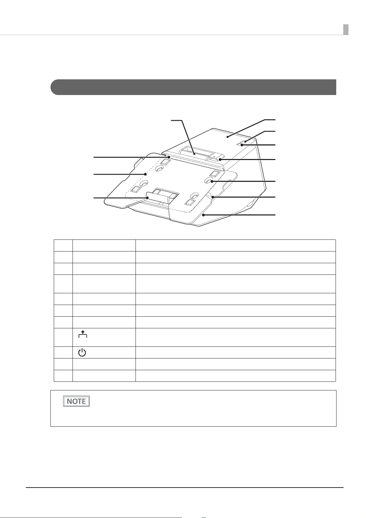
Front
Chapter 1 Product Overview
1 Upper tablet holder Holds the upper side of a tablet.
2 Tablet table (standard) Place a tablet on this table.
3 Lower tablet holder Holds the lower side of a tablet.
4 Security slot Use here to attach an anti-theft tool such as a wire. This slot is provided on both sides
of the printer.
5 Lock lever Operate this lever to secure a tablet.
6 Screw The screws are securing the tablet table.
7 Cover open lever Operate this lever to open the roll paper cover.
8 Feed button Press this button once to feed the roll paper for one line. Hold down this button to
continue feeding the roll paper.
9 Power switch This switch turns the printer on or off.
10 Roll paper cover Open this cover when installing or replacing the roll paper.
11 Panel LED For explanation of the LEDs, see "Panel LED" on page 17
When turning off the printer without using the power switch, it is recommended to send a power-
ff command to the printer. If you use the power-off sequence, the latest maintenance counter val-
o
ues are saved. (Maintenance counter values are usually saved every two minutes.)
For information about ESC/POS commands, see the ESC/POS Command Reference.
15
Page 16
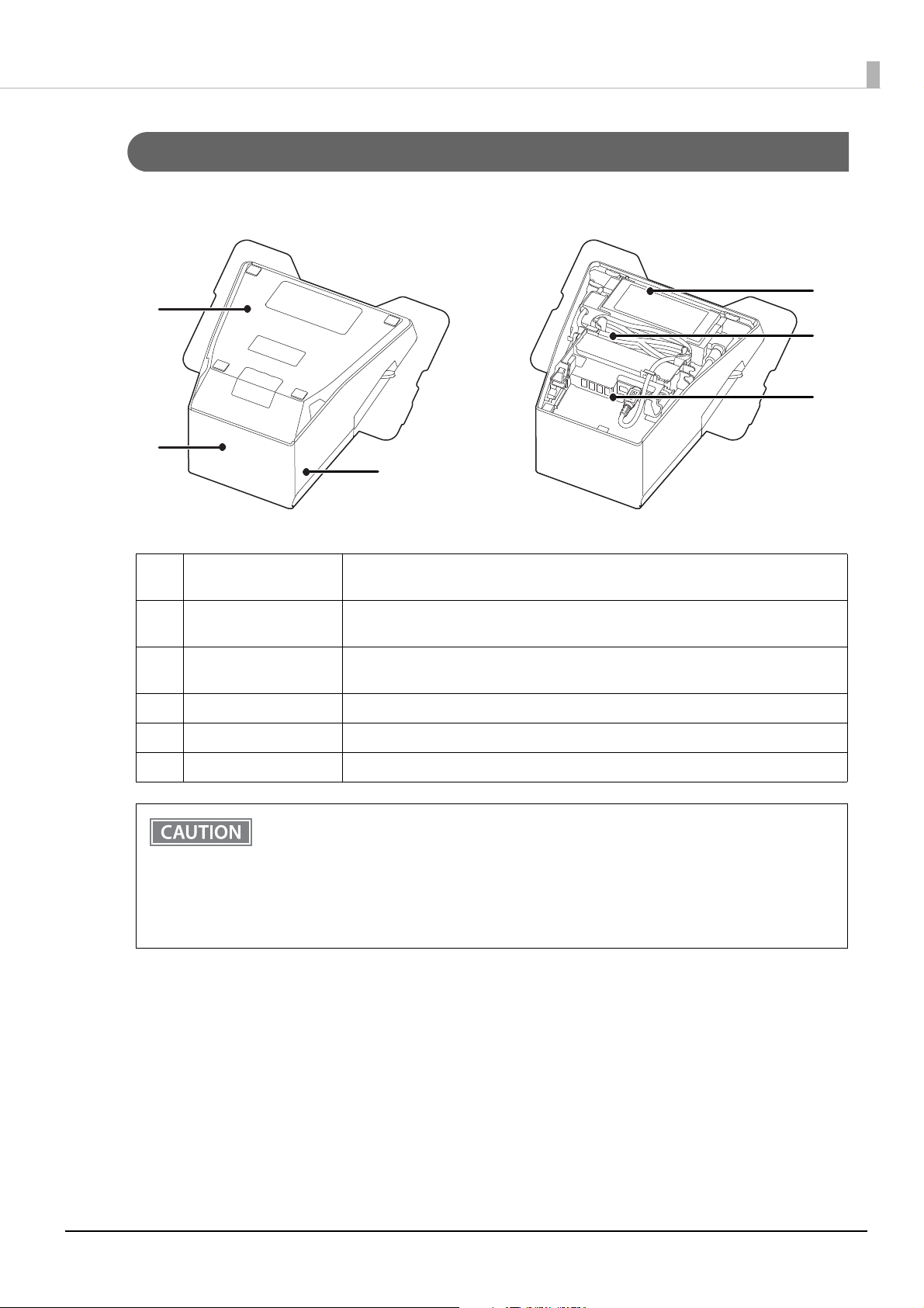
Bottom
1
2
4
5
6
3
Chapter 1 Product Overview
1 Bottom cover Remove this cover when connecting interface cables to the connectors inside the
printer.
2 Rear cover Remove this cover when connecting interface cables to the connectors inside the
printer.
3 Side cover Remove this cover when connecting interface cables to the connectors inside the
printer.
4 Connectors For connecting various devices to the printer.
5 DC cable The AC adapter supplies power to the printer through this cable.
6 AC adapter Supplies power to the printer.
• Be sure to use the specified AC adapter (PS-180) only. Using another AC adapter may result in
fire or electric shock.
• Never insert the AC cable plug into a socket that does not meet the input voltage of the AC
adapter. Doing so may result in damage to the printer.
• Should a fault ever occur, immediately turn off the power to the printer and unplug the AC
cable from the socket.
• Use only the AC cable that came with the printer.
16
Page 17
Chapter 1 Product Overview
Panel LED
Power LED
• Lights when the power supply is on.
• Off when the power supply is off.
• Flashes during the network to start up, when waiting for power off, or updating firmware.
Do not turn on by using the power switch while waiting for the power to turn off (when the Power
LED is flashing). Otherwise, it may not startup correctly.
Error LED
• Lights or flashes when an error occurs. (For information about the flashing patterns, see "Status and Errors"
on page 21.)
ights after the power is turned on or after a reset (offline). Automatically goes out after a while to indicate
• L
that the printer is ready.
• Off when the printer is in standard mode (online).
Paper LED
• Lights when the roll paper is out.
• Flashes to urge user to operate the Feed button.
This LED also lights when the remaining amount of roll paper becomes low if the roll paper nearend detection function has been enabled. The function can be used when placing the printer
vertically and using 80 mm width roll paper.
For more details about the detection setting, see "Software Settings" on page 81.
F
or more details about the near-end detection, see "Enabling the Roll Paper Near-End Detection"
on
page 71.
Wi-Fi LED
• Lights while the printer is connected to Wi-Fi.
• Off while the printer is not connected to Wi-Fi or while the printer is connected to a wired LAN.
• Flashes while communication is temporarily disabled because an IP address has not been acquired or for
other reason.
Ethernet LED
• Lights while the printer is connected to Ethernet.
• Off while the printer is not connected to Ethernet or while the printer is connected to Wi-Fi.
• Flashes while communication is temporarily disabled because an IP address has not been acquired or for
other reason.
Bluetooth LED
• Lights while the printer is connected via Bluetooth.
• Off while the printer is not connected via Bluetooth.
• Flashes while the printer is waiting to be paired with another device.
17
Page 18
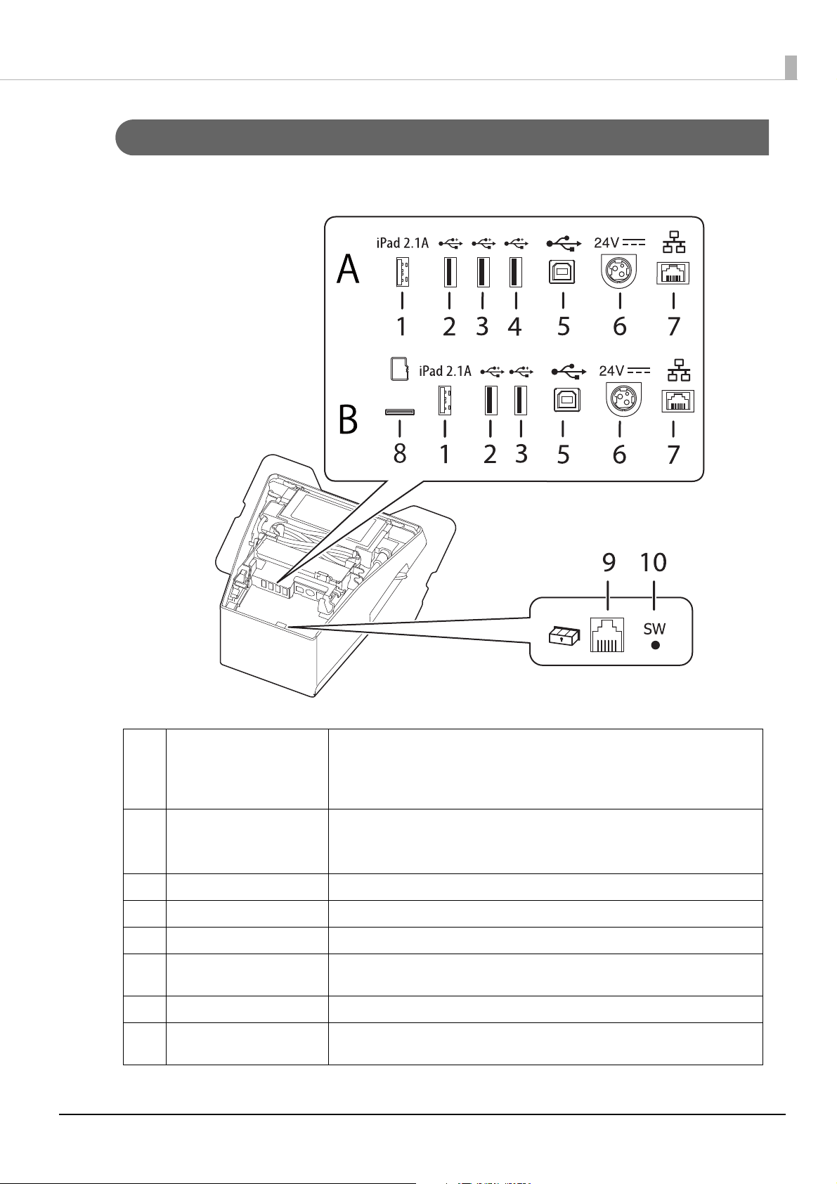
Connectors
A: Printer models without a microSD card slot
B: Printer models with a microSD card slot
Chapter 1 Product Overview
1 USB connector (USB-A - De-
vice Charging)
Color of the USB connector: white
2,3,4USB connector (Type-A)
Color of the USB connector: black
5 USB connector (Type-B) Connects the USB cable for connecting to computers.
6 Power supply connector Connects the DC cable for the AC adapter.
7 Ethernet connector Connects the 10BASE-T/100BASE-TX LAN cable.
8 microSD card slot For a special purpose and cannot be used for daily use. For more details, contact
9 Drawer kick connector Connects the modular cable for the cash drawer.
10 Status sheet button Use this button to print a status sheet on interfaces or initialize the settings on
Connects a USB cable of a tablet. Enables communication with the tablet while
charging the tablet.
No power is supplied to the connected tablet if the printer is turned off.
Connects a USB cable of a peripheral device such as an optional Wireless LAN
cable set, customer display, or handheld scanner.
No power is supplied to the connected device if the printer is turned off.
Epson sales partner.
interfaces.
18
Page 19

Chapter 1 Product Overview
About the USB connector (USB-A - Device Charging, The white USB connector)
• Make sure you use the genuine cable for the tablet, smartphone, or USB device you are using.
• Charging may not be performed depending on the device's charging specifications.
• To set an optimum current value for charging the connected device, it may take several
seconds before charging starts. Charging may stop temporarily immediately after the device is
connected.
• If a device connected to the USB connector (USB-A Device Charging) has a rated power that
exceeds the rated current of the USB connector, charging the device is stopped. See "Product
Specifications" on page 131.
• T
he device may not be fully charged depending on its settings or usage conditions. For
example, when the device is used with the screen brightness set to its maximum, and/or with
the sleep function disabled.
• Seiko Epson Corporation assumes no responsibility for economic damages or problems arising
from failure of charging the connected device due to a failure or malfunction of the product.
• It may be hard to disconnect some types of USB cable. Do not forcibly pull the cable, or the
USB connector and USB cable may be damaged. Contact qualified service personnel if you
encounter the trouble.
• To communicate with a tablet computer via Bluetooth while charging the tablet through the
USB connector (USB-A - Device Charging) on the printer, set the "Interface selection" setting to
"Bluetooth only". For more details, see "Software Settings" on page 81.
How
ever, if you do so, the maximum supply current is limited to 0.5 A, which may not be
enough for charging some types of tablet. Please use the tablet after testing and evaluating it
adequately.
• When connecting an Android device to the USB connector (USB-A - Device Charging) for data
communication, make sure that the device satisfies the following requirements.
Requirements: The version of Android OS is 10 or later with kernel version 4.9.15 or later
However, Epson does not guarantee normal operation of all Android devices even if they
satisfy the requirements. Run some tests before actually using the device.
• If the printer is connected to a wired network, an iOS tablet connected to the printer via the
USB connector can access the network through the Lightning to USB cable. For more details,
see "Network Tethering (iOS device only)" on page 109
19
Page 20

Chapter 1 Product Overview
Online and Offline
Online
The printer is online and ready for normal printing unless there is a reason to go offline.
Offline
The printer automatically goes offline under the following conditions:
• While the printer power is turning on/off
• During the setting and check modes operating (except the hexadecimal dumping mode) (See "Setting/Check
des" on page 95.)
Mo
hile roll paper is fed using the Feed button
• W
• When the printer stops printing due to a paper end (when the paper out detector detected the paper out)
• During an operation standby state
• When an error has occurred (See "Status and Errors" on page 21.)
hile the roll paper cover is open
• W
20
Page 21
Status and Errors
The status of the printer is indicated by lit and flashing LEDs.
You cannot print when an error has occurred.
You cannot identify the error by the flashing patterns of the LEDs. Develop the application so that
users can identify the error description and check the solutions.
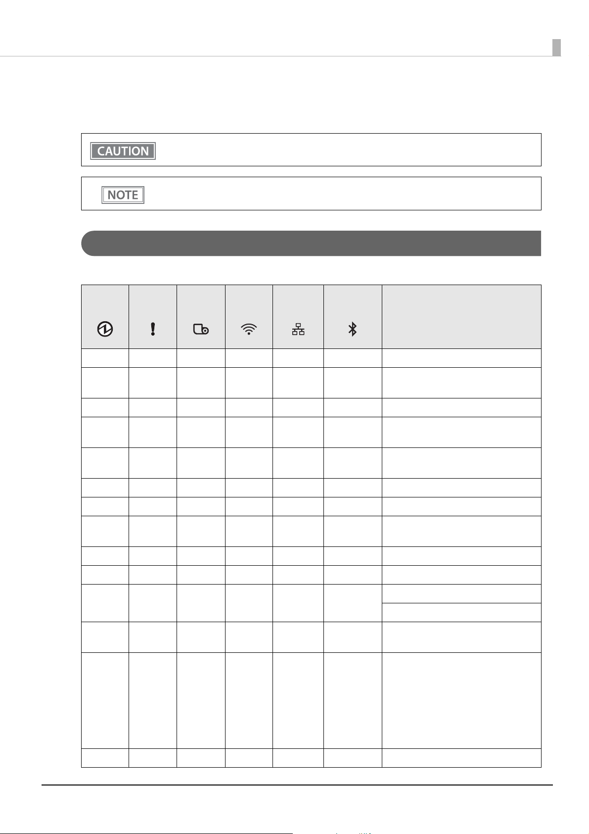
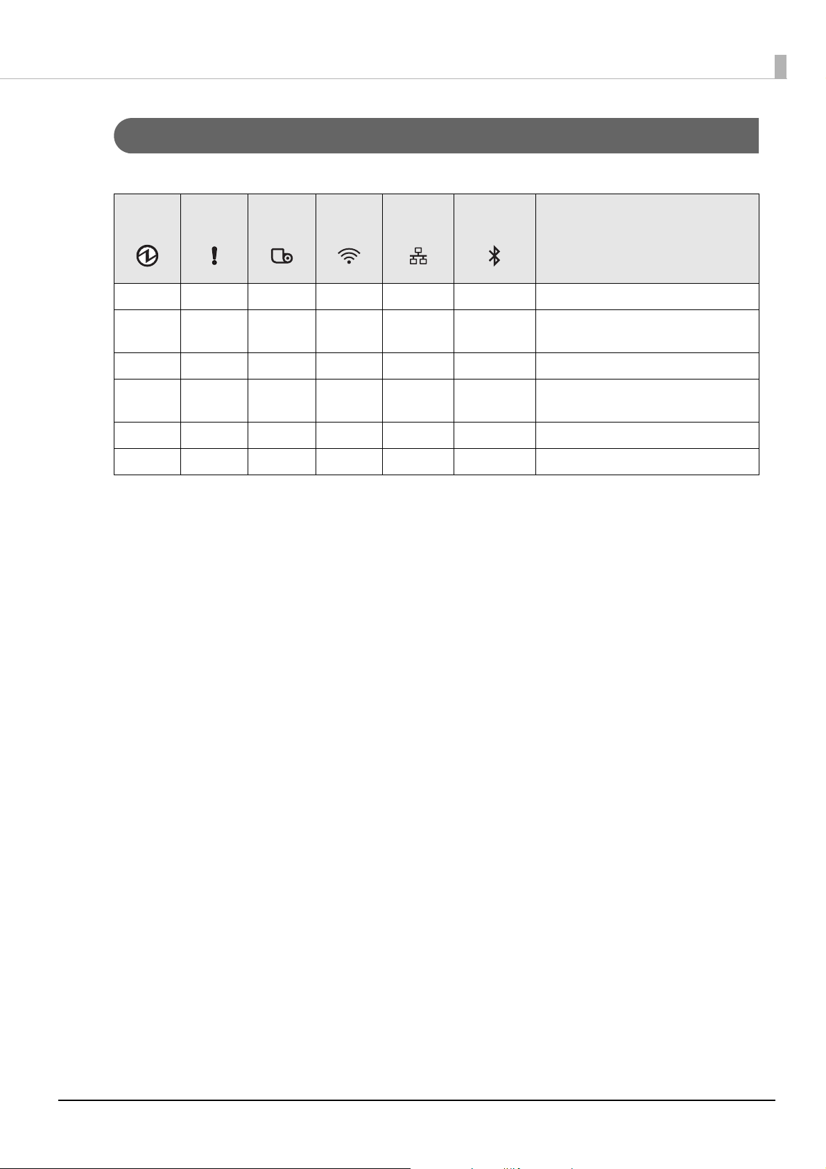
Status Display
Chapter 1 Product Overview
O: OFF N: ON F: Flashing -: Ignore the LED light
Power
LED
NOO -- -Online
NNNN N N
NO - OO ODuring a self-test
NO -- - -
NN -- - -
NOFO O OWaiting for the self-test to continue
NOF - - - Waiting for a Macro execution to run
NNF -- -
NNN - - - No roll paper
NON - - - Remaining amount of roll paper is low*
Error
LED
Paper
LED
Wi-Fi
LED
Ethernet
LED
Bluetooth
LED
Printer Status
While initializing after turning on the
power
While feeding paper using the Feed
button
Roll paper cover open while not printing
Waiting for the roll paper cover to be
closed to print a status sheet.
1
NN -- - -
N F *2 - - - -
N F - OO O
FOOO O OUpdating firmware
Automatically Recoverable Errors
Recoverable Errors
The connected device can only be
charged through the USB port.
Unrecoverable Errors
CAUTION:
Turn off the power immediately when
an unrecoverable error occurs.
If the same error occurs again even after
turning the power back on, contact
qualified service personnel.
21
Page 22
Chapter 1 Product Overview
Power
LED
FOFO O O
F *3 N O O O O During turn-off process
F *4 OOOO O
F *5 O -- - -
Error
LED
Paper
LED
Wi-Fi
LED
Ethernet
LED
Bluetooth
LED
Printer Status
While forced updating firmware mode is
on
During power off
NOTE:
The printer enters this status while processing the power off command. It is
recommended to use this method
when you need to save information on
the printer’s operating status if the
power is cut without using the power
switch.
A warning about TM-Intelligent
function
*1: To detect this status (remaining amount of roll paper is low), enable the "Roll paper near-end detection"
function. The function can be used when placing the printer vertically and using 80 mm width roll paper.
For more details about the detection setting, see "Software Settings" on page 81. For more details about near-
detection, see "Enabling the Roll Paper Near-End Detection" on page 71.
end
*2:
The Error LED flashing pattern is: turning on and off alternately at 320 ms intervals for five seconds, then
goes off.
*3: The Power LED flashing pattern is: lighting for 320 ms followed by a pause for 320 ms.
*4: The Power LED flashing pattern is: lighting for 160 ms followed by a pause for 2400 ms.
*5: The Power LED flashing pattern is: lighting for 4960 ms followed by a pause for 160 ms.
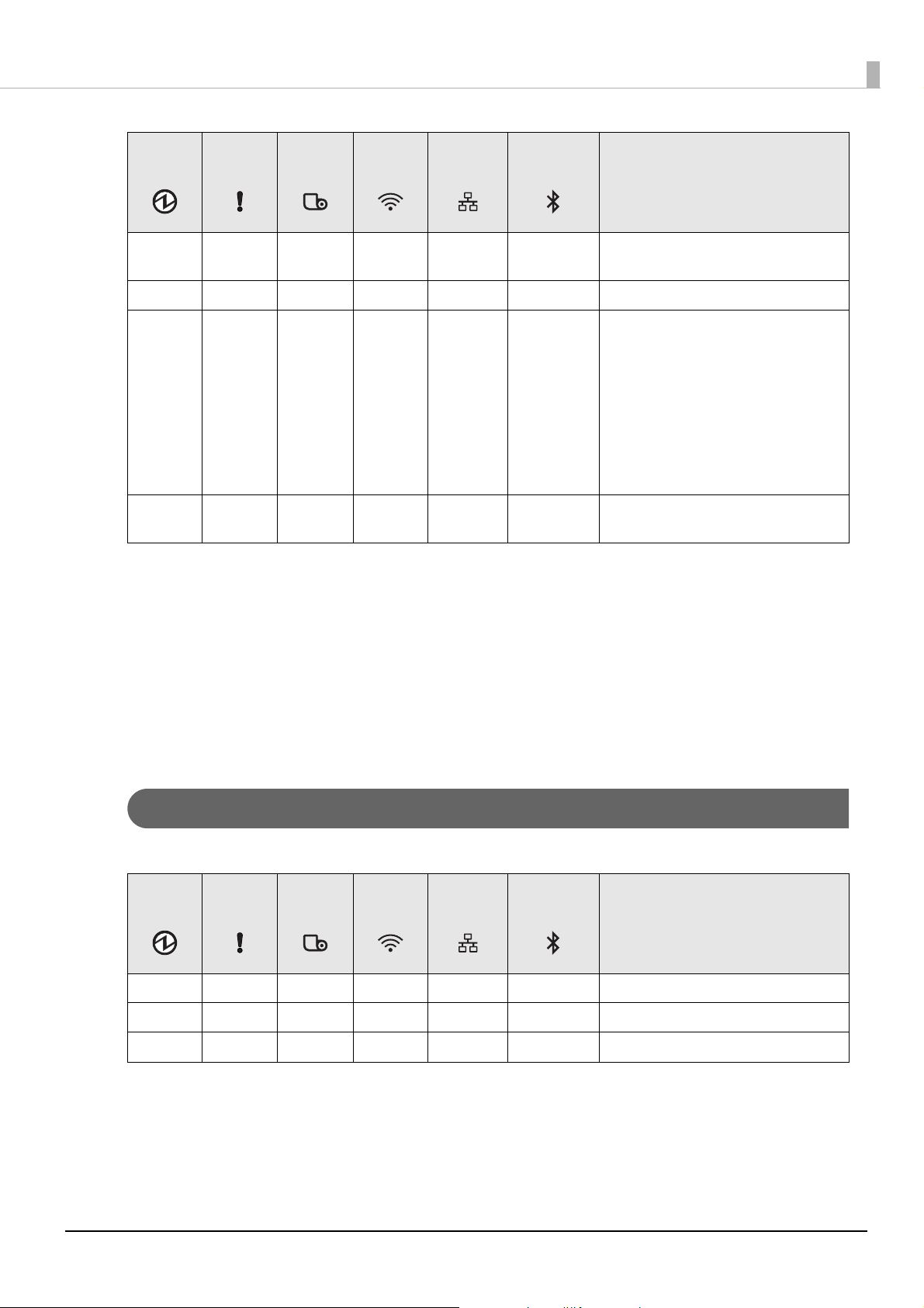
Bluetooth Connection Status
O: OFF N: ON F: Flashing -: Ignore the LED light
Power
LED
NOO -- F Waiting to be paired with a device
NOO -- N Connecting via Bluetooth
NOO -- O Not connected via Bluetooth
Error
LED
Paper
LED
* The LED flashing pattern is: lighting for 320 ms followed by a pause for 320 ms.
Wi-Fi
LED
Ethernet
LED
Bluetooth
LED
Printer Status
22
Page 23
Network Connection Status
Chapter 1 Product Overview
O: OFF N: ON F: Flashing -: Ignore the LED light
Power
LED
NOON O - Connecting via Wi-Fi
NOOF O -
NOOO N - Connecting via Ethernet
NOOO F -
NOOF F - Starting the network firmware
NOOO O - Not connected to a network
Error
LED
Paper
LED
Wi-Fi
LED
Ethernet
LED
Bluetooth
LED
Printer Status
Wi-Fi (An IP address has not been
acquired)
Ethernet (An IP address has not been
acquired)
* The LED flashing pattern is: lighting for 320 ms followed by a pause for 320 ms.
23
Page 24
Chapter 1 Product Overview
Error Status
There are three possible error types: automatically recoverable errors, recoverable errors, and unrecoverable
errors.
Automatically Recoverable Errors
• Head temperature error The printer recovers from the error when the head tem-
perature drops.
• Cover open error (in the middle of printing) The printer recovers from the error when the roll paper
cover is closed.
• TM-Intelligent function error The printer recovers from the error when the printer set-
tings are corrected.
Recoverable Errors
• Autocutter error An error occurs if the cutter is locked due to fallen foreign material or
similar cause. Although automatic recovery is performed even if there
is only slight locking, if automatic recovery is not performed, remove
foreign material and paper jams, and close the roll paper cover to perform recovery.
Instead of closing the roll paper cover, you can make the printer recover from the error using a
dedicated command, however, doing so will cause the printer to go offline due to a cover open
error.
Unrecoverable Errors
• These include a high voltage error, CPU execution error, and communication unit error. If the error persists
after turning the printer off and then on again, the printer may be defective. Contact qualified service personnel.
Turn off the power immediately when an unrecoverable error occurs.
24
Page 25

Chapter 1 Product Overview
NV Memory (Non-Volatile Memory)
The printer's NV memory stores data even after the printer power is turned off. NV memory contains the
following memory areas for the user:
• NV graphics memory
• User NV memory
• Memory switches (customized values)
• R/E (Receipt Enhancement)
• Maintenance counter
As a guide, NV memory rewriting should be used 10 times or less a day when you program
applications.
NV Graphics Memory
Graphics, such as shop logos to be printed on receipts, can be registered.
To register your graphics data, use TM-m30II Utility or ESC/POS commands.
You can check registered graphics data using TM-m30II Utility or by printing the data in the NV graphics
information print mode.
User NV Memory
You can store and read text data for multiple purposes, such as for storing a note including customizing or
maintenance information of the printer.
Memory Switches (customized values)
With the memory switches, which are software switches for the printer, you can configure various settings of the
printer. For information about the memory switch, see "Software Settings" on page 81.
R/E (Receipt Enhancement)
You can set the graphics data, such as a shop logo, registered in the NV graphics memory to be printed on the
top of each receipt or to be printed on the bottom of each receipt just before the paper is cut.
To make the settings, use TM-m30II Utility or ESC/POS commands.
You can check the settings using TM-m30II Utility or by printing the settings information in the Receipt
enhancement information print mode.
25
Page 26

Chapter 1 Product Overview
Maintenance Counter
With this function, printer information, such as the number of lines printed, the number of autocuts, and
printer operation time after the printer starts working, is automatically stored in printer's memory. You can read
the counter information to use it for periodical checks or part replacement.
• You can also check the head running length and number of times of autocutting with the selftest (see "Self-test Mode" on page 97).
• The maintenan
minutes (up to four minutes). However, the values are not saved when the printer is in powersaving mode or when it is turned off without the use of the power switch.
ce counter values are automatically saved in the NV memory usually every two
26
Page 27
Chapter 1 Product Overview
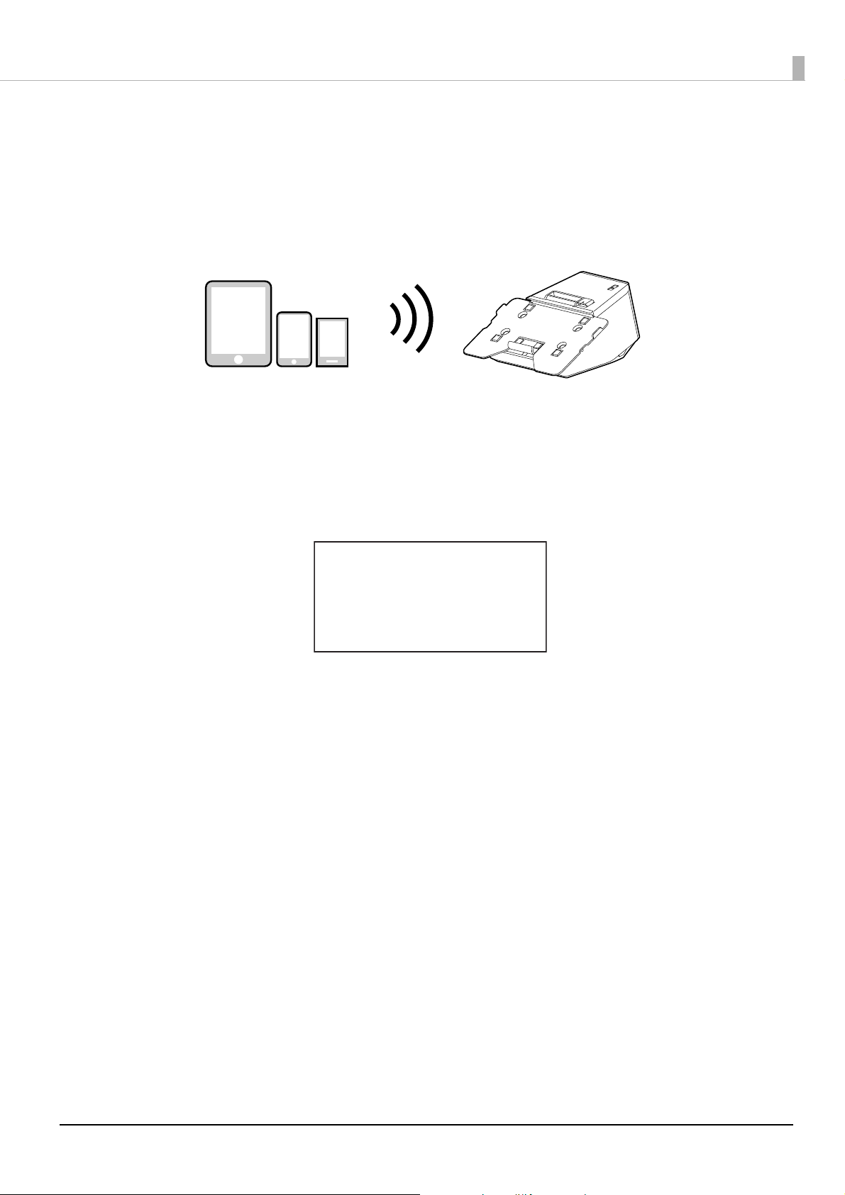
Simple Setup for Wireless LAN
This printer comes with a mode (SimpleAP) that allows printers to connect with a smart device or a computer
without requiring a wireless access point. This allows you to easily setup a wireless LAN for the printer by using
a printer settings tool (Epson TM Utility, EpsonNet Config, or EpsonNet Config (Web version)) even without a
network environment such as access points.
When the wireless LAN settings of the printer have not been changed from the factory default, and the printer is
turned on, the printer automatically enters the Simple AP mode and prints the following information. If you
have changed the wireless LAN settings from the factory default, start the printer according to the settings to
connect the printer to an access point.
SimpleAP Start
SSID
Encryption Type
Passphrase
IP Address
MAC Address
: EPSON_Printer
: WPA2-PSK
: 12345678
: 192.168.192.168
: xx-xx-xx-xx-xx-xx
27
Page 28
Chapter 1 Product Overview
Useful Functions for Smart Devices
You can easily connect this product to the network by using the QR code printed on the status sheet.
QR Code
Capture the QR code printed on the status sheet with the camera on your smart device to acquire the printer
information (information for specifying the device).
By using the acquired information, the device can specify the printer to send a print job over a network or
Bluetooth.
• Programming using Epson ePOS SDK is required to use these functions. These functions are
created by combining QR code capturing operations and the target printer specifications using
Printer Easy Select API.
See the "Epson ePOS SDK for Android/iOS User's Manual" and the Epson ePOS SDK sample
program for more details. The sample program also contains a sample implementation method for
capturing a QR code.
• You can try a demo of these functions by using Epson TM Utility for iOS/Android.
28
Page 29
Chapter 1 Product Overview
Printing Using Multiple Interfaces
In models with multiple interfaces, you can use all interfaces without any limitations on which interface is to be
used. You can use this function to temporarily connect a smart device to a nearby printer and print.
The printer provides each interface with an independent receive buffer and switches the active interface
depending on the priority, while handling data in each receive buffer.
You can set one interface for the main connection. Data received from the main connection interface is handled
with the highest priority.
By default, the interface that receives the first data transfer is set as the main connection interface; however, you
can select the main connection interface in advance.
When the receive buffer for the active interface becomes empty and a preset time period (one second by default)
has passed, switching to another interface is enabled, and an interface that receives print data becomes active.
When you do not use the Bluetooth function, set the Bluetooth security level to "Middle" or "High"
to prevent unauthorized access to the printer over Bluetooth. You can change the security level by
using Epson TM Utility, TM-m30II Utility, or in the Interface Setup mode.
You can select the main connection interface and set the time to enable interface switching from
the software settings. For details on software settings, see "Software Settings" on page 81.
29
Page 30
Chapter 2 Setup of the Tablet
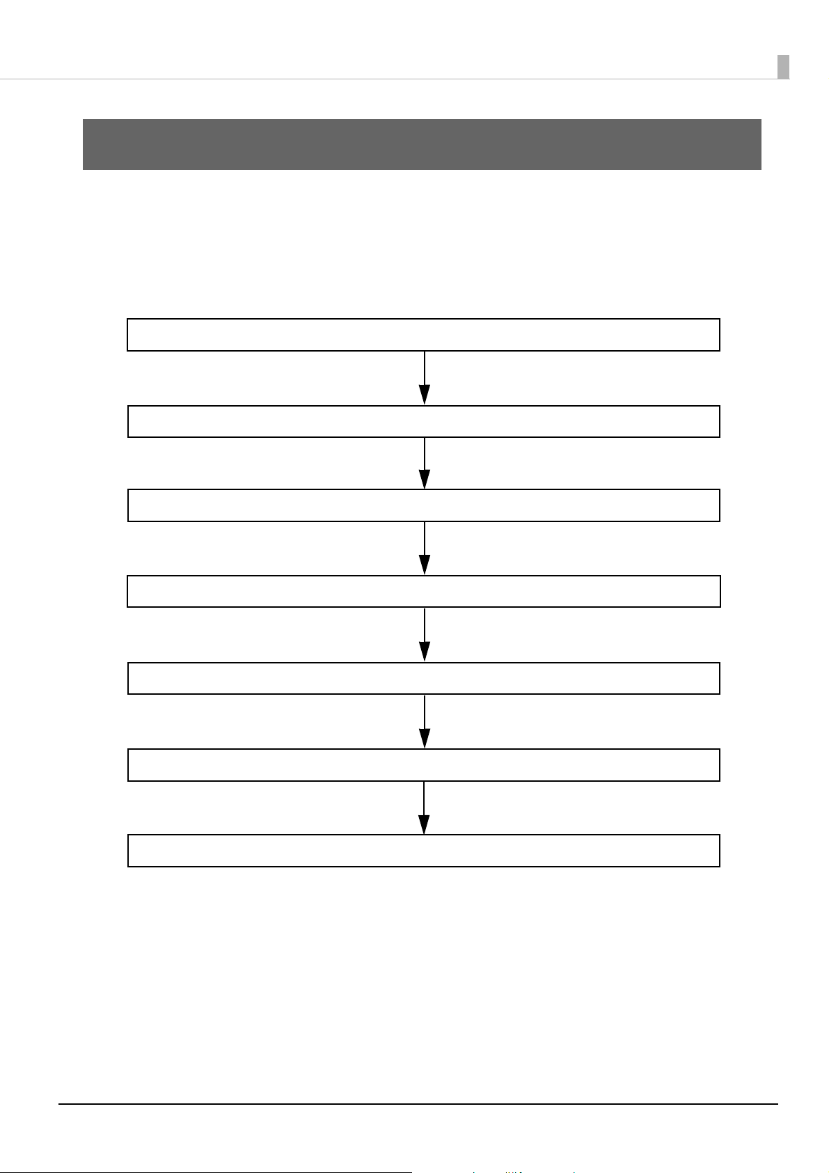
5. Connecting the AC Cable (page 42)
4. Connecting Peripheral Devices (page 41)
3. Mounting the Front Tablet (page 36)
1. Tablets that Can be Mounted to the Printer (page 31)
2. Preparation for Setup (page 35)
7. Replacing the Tablet Table (page 46)
6. Attaching the Lock Lever Cover (page 45)
Setup of the Tablet
This chapter describes how to mount your tablet or display to the printer.
Flow of Setup
On the following pages, the tablet/display mounting procedure is provided in the order shown below.
30
Page 31

Tablets that Can be Mounted to the Printer
You can mount your tablet to the printer as if the tablet is a built-in display.
1: Front tablet
2: Rear display (OT-DM30SL)
Chapter 2 Setup of the Tablet
31
Page 32

Front Tablet
Mountable Tablet Sizes
The maximum size of tablet that can be mounted to the printer is as shown below.
304 x 216 mm {12.0 x 8.5"} (height x width), 9 mm {0.35"} (depth)
Make sure that your tablet does not stick out from the tablet table.
Chapter 2 Setup of the Tablet
Use one of the tablet tables appropriate for the size of your tablet.
Tablet size mountable to the tablet table
Tablet table size
Width Height
Standard Approx. 176 mm {6.9"} or less Approx. 282 mm {11.1"} or less
Large Approx. 216 mm {8.5"} or less Approx. 304 mm {12.0"} or less
For instructions on how to replace the tablet table, see the page below.
U "Replacing the Tablet Table" on page 46
32
Page 33

Chapter 2 Setup of the Tablet
Mountable Tablet Types
The tablets that can be connected to the printer and the available USB connectors are as shown below. To know
the location of the USB connectors, see "Connectors" on page 18.
"Z" m
"P" means that availability varies by device to device.
"--" means that it is not supported.
eans that the device can be connected.
Type Product name
USB connector
USB-A - Device Charging
(up to 2.1 A)
Data
communication
Charging Charging
USB-A
(up to 0.5 A)
Type-B
Data
communication
Tablet table
Apple
*1*6
device
Windows tablet
Android device
*1 A device equipped with a Lightning connector can be used.
Use a genuine Apple or MFi Certified Lightning to USB Cable. If you use a non-certified (non MFi) Lightning Cable,
or use an extension cable, data communication and charging may not be performed normally.
*2 When a tablet computer is connected to the USB-A - Device Charging connector, the Bluetooth function of the
printer is disabled. To charge the device keeping it connected via Bluetooth, change the Interface selection setting
to "Bluetooth only". For more details, see "Software Settings" on page 81.
Ho
wever, if you do so, the maximum supply current is limited to 0.5 A, which may not be enough for charging some
types of tablet. Please use the tablet after testing and evaluating it adequately.
*3 Depending on the settings or usage conditions of the device, it may not be fully charged. To fully charge the device,
darken its screen or take such other measures to reduce power consumption.
iPad (5th generation)
iPad (6th generation)
iPad (7th generation)
iPad Air 2
iPad Pro (3rd generation)
iPad Pro (4th generation)
iPad mini 4 ZP
*6
*6
ZP*2-- -- Standard
-- -- -- -- Large
*2
-- -- -- Z
*4
P
*2
P
*3
Z
-- P
-- Standard
Standard/
Large
*5
Standard/
Large
*4 When connecting an Android device for data communication, make sure that the device satisfies the following
requirements.
Requirements: The version of Android OS is 10 or later with kernel version 4.9.15 or later
However, Epson does not guarantee normal operation of all Android devices even if they satisfy the requirements.
Run some tests before actually using the device.
*5 The device must be compatible with an OTG cable and must be capable of acting as a USB host.
*6 For more detailed information about tablets that can be used with the printer, see the link below.
www.epson-biz.com/?content=sht_tmm30ii-sl_tablet
If your tablet is not allowed to connect to the USB connector of the printer, pull out its cable
t
hrough the cutout of the printer just like the AC cable.
33
Page 34

Chapter 2 Setup of the Tablet
Rear Display
You can mount the optional OT-DM30SL to the printer as a rear display. For instructions on how to mount it, see the
page below.
U "Mounting OT-DM30SL" on page 72
34
Page 35

Chapter 2 Setup of the Tablet
Preparation for Setup
Make the following preparations to mount a tablet to the printer.
Preparation of Tablet
Prepare a tablet to be used as a front tablet, and a cable to connect the tablet and the printer. The tablet cable can
be routed through either left or right side of the printer.
U "Tablets that Can be Mounted to the Printer" on page 31
Routing the Cables
The AC cable and interface cables can be pulled out from the left, right, rear, or bottom of the printer. According
to the place you install the printer, determine which direction to route the cables.
To pull out the cables from the rear of the printer, cut out one portion of the bottom cover.
35
Page 36

Mounting the Front Tablet
Follow the procedure below to mount the front tablet to the printer.
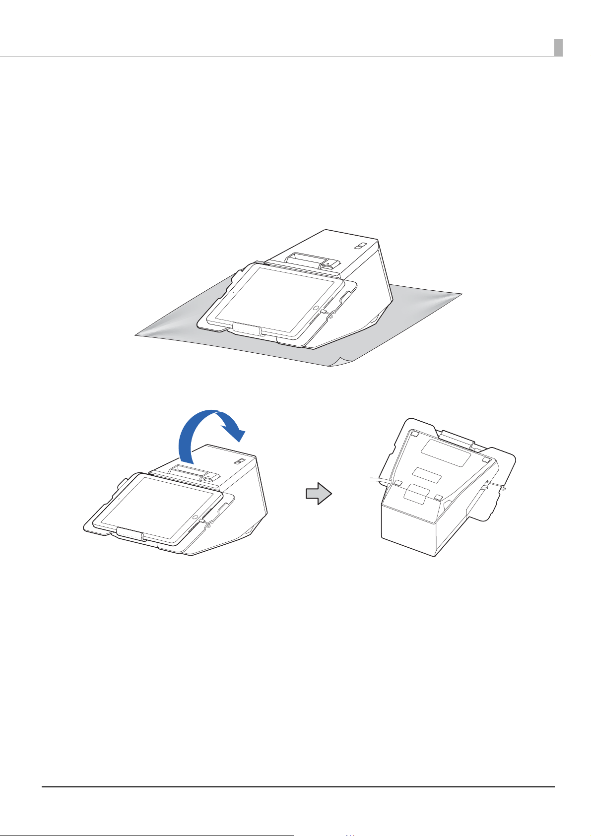
Put the printer on a soft cloth or cushioning material.
1
Operate the lock lever to extend the lower tablet holder.
2
Chapter 2 Setup of the Tablet
Connect the cable to the front tablet.
3
36
Page 37

Chapter 2 Setup of the Tablet
Place the tablet so that its upper edge contacts with the upper tablet holder.
4
Move the lower tablet holder up to sandwich the tablet between the two holders,
5
and then operate the lock lever to secure the tablet.
If the tablet sticks out from the tablet table, replace the tablet table with the large one.
U "Replacing the Tablet Table" on page 46
37
Page 38

Turn over the printer.
6
Chapter 2 Setup of the Tablet
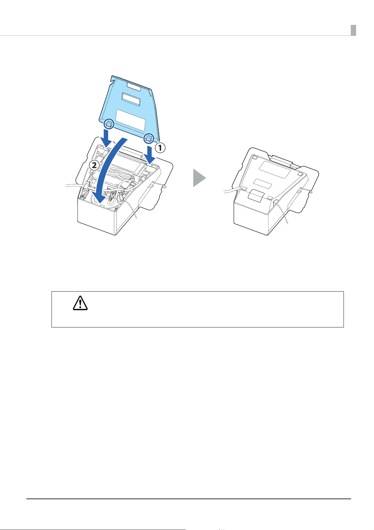
Remove the bottom cover.
7
38
Page 39

Remove the side covers.
8
Remove the rear cover.
9
Chapter 2 Setup of the Tablet
10
Pass the cable through the hook on the side.
39
Page 40

11
Chapter 2 Setup of the Tablet
Roll up the cable on the side as shown below to adjust the cable length.
12
Connect the cable to the appropriate USB connector.
If your tablet is not allowed to connect to the connector of the printer, pull its cable out
through the cutout of the printer.
40
Page 41

Connecting Peripheral Devices
Connect an interface cable of a peripheral device to the connector inside the printer.
Connect an interface cable to the connector inside the printer.
1
For information on which connector is which type, see "Connectors" on page 18.
A: Printer models without a microSD card slot
B: Printer models with a microSD card slot
Chapter 2 Setup of the Tablet
Pass the interface cable through the hook.
2
This step is not necessary when pulling the cable out from the rear or bottom of the printer,
41
Page 42

Connecting the AC Cable
Follow the procedure below to connect the AC cable.
Connect the AC cable to the AC adapter.
1
Chapter 2 Setup of the Tablet
Route the AC cable.
2
The AC cable can be pulled out from the left, right, rear, or bottom of the printer.
"Routing the Cables" on page 35
Route the cable according to the direction that you pull out it.
O When pulling out from the left side of the printer
O When pulling out from the rear or bottom of the printer
When pulling out the cable from the bottom, put the AC plug through the cutout of the
bottom cover in advance.
42
Page 43

O When pulling out from the right side of the printer
Attach the rear cover.
3
Chapter 2 Setup of the Tablet
Attach the side covers.
4
43
Page 44

Attach the bottom cover.
5
Pull out the AC cable from the left, right, rear, or bottom of the printer.
Chapter 2 Setup of the Tablet
Now mounting the tablet to the printer is finished.
44
Page 45

Chapter 2 Setup of the Tablet
Attaching the Lock Lever Cover
Attach the lock lever cover to the lock lever to prevent unintended operation of the lever. This also helps in
preventing the tablet from being stolen.
45
Page 46

Replacing the Tablet Table
Depending on the size of your tablet, replace the tablet table.
See "Front Tablet" on page 32 for information of mountable tablet sizes.
Operate the lock lever to extend the lower tablet holder.
1
Remove the screws by turning them with a coin or similar tool.
2
Chapter 2 Setup of the Tablet
46
Page 47

Replace the tablet table, and then secure the table with the screws.
3
Chapter 2 Setup of the Tablet
47
Page 48

Chapter 3 Setup of the Printer
6. Connecting the Optional External Buzzer (page 60)
5. Connecting the Customer Display (page 59)
4. Connecting the Wireless LAN Unit (page 58)
3. Connecting Peripheral Devices (page 53)
1. Placing the Printer (page 49)
2. Changing the Paper Width (page 52)
8. Connecting to the Power Source (page 63)
7. Connecting the Cash Drawer (page 61)
9. Connecting the Printer to the Host Devices (page 64)
10. Attaching the Power Switch Cover (page 70)
11. Enabling the Roll Paper Near-End Detection (page 71)
Setup of the Printer
This chapter describes setup and installation of the product and peripherals.
Flow of Setup
This chapter consists of the following sections along with the setup flow of the product and peripherals.
48
Page 49

Placing the Printer
The printer can be placed either horizontally or vertically.
• Do not place the printer in locations subject to high dust levels.
• Do not give a high impact on the printer during operation. Doing so may cause the print failure.
• Be careful not to place cords or foreign substances under the printer.
• When using a cash drawer, secure the printer to prevent it from moving due to vibrations.
Placing the Printer Horizontally
Install the printer on a level and flat surface.
The roll paper is ejected from the top side, and the roll paper cover opens upward.
Chapter 3 Setup of the Printer
How to Secure the Printer
If you want to secure the printer to the installation site such as a table, use the optional tape (model number:
DF-10).
Follow the procedure below to secure the printer with the tape.
Turn off the printer.
1
Disconnect the AC cable from the power outlet.
2
Turn over the printer.
3
Remove the backing sheet from the tape.
4
49
Page 50

Chapter 3 Setup of the Printer
Attach four pieces of the tape to the bottom of the printer, and then remove another
5
backing sheet from each tape.
Place the printer on the installation surface, and then hold the printer down to secure it.
6
• The tape is hook and loop fastener. To remove the printer from the installation surface
disengaging the hook and loop fastener tape, apply a force to peel the printer from the surface.
However, if you repeat removing and reattaching the tape multiple times, the tape may become
less cohesive. In such case, replace the tape (DF-10) with new ones.
• Since four pieces of the tape need to be attached to the printer, you need two sets of DF-10 at a
time.
Placing the Printer Vertically
There are the following two methods to place the printer vertically.
• Using the optional DF-10 tape, stand the printer on a table.
U "How to Stand the Printer" on page 51
sing the optional OT-WH30SL hanging bracket set, hang the printer on a wall.
• U
U "OT-WH30SL (Wall Hanging Bracket Set)" on page 78
The roll paper is ejected from the front side, and the roll paper cover opens frontward.
50
Page 51

Chapter 3 Setup of the Printer
How to Stand the Printer
Follow the procedure below to stand the printer vertically on a table.
Place the printer on a level and flat surface.
Make sure to secure the printer using the DF-10 tape. If you just place the printer on a table, the
printer may fall over when it or mounted tablet is pressed hard.
Turn off the printer.
1
Disconnect the AC cable from the power outlet.
2
Remove the backing sheet from the tape.
3
Attach four pieces of the tape to the bottom of the printer, and then remove another
4
backing sheet from each tape.
Place the printer on the installation surface, and then hold the printer down to secure it.
5
• The tape is hook and loop fastener. To remove the printer from the installation surface
disengaging the hook and loop fastener tape, apply a force to peel the printer from the surface.
However, if you repeat removing and reattaching the tape multiple times, the tape may become
less cohesive. In such case, replace the tape (DF-10) with new ones.
• Since four pieces of the tape need to be attached to the printer, you need two sets of DF-10 at a
time.
51
Page 52

Chapter 3 Setup of the Printer
Changing the Paper Width
You can change the paper width from 80 to 58 mm by installing the included 58-mm width roll paper guides.
Follow the steps below to change the paper width.
Once you change the paper width to 58 mm and print on 58-mm width roll paper, you cannot go
back to 80 mm width. Because parts of the print head that do not normally touch the paper may be
damaged by the platen roller, and the autocutter may wear out.
Turn off the printer.
1
Open the roll paper cover.
2
Align the three projections on the roll paper guides with the rectangular holes in the
3
printer, and then push the guides inward.
Set the paper width in software setting mode.
4
For information about the software setting mode, see "Software Settings" on page 81.
52
Page 53
Connecting Peripheral Devices
Connect an interface cable of a peripheral device to the connector inside the printer.
Turn off the printer.
1
Disconnect the AC cable from the power outlet.
2
Put the printer on a soft cloth or cushioning material.
3
Chapter 3 Setup of the Printer
Turn over the printer.
4
53
Page 54

Remove the bottom cover.
5
Chapter 3 Setup of the Printer
Remove the side covers.
6
Remove the rear cover.
7
54
Page 55

Connect an interface cable to the connector inside the printer.
8
For information on which connector is which type, see "Connectors" on page 18.
A: Printer models without a microSD card slot
B: Printer models with a microSD card slot
Chapter 3 Setup of the Printer
Pass the interface cable through the hook.
9
This step is not necessary when pulling the cable out from the rear or bottom of the printer,
55
Page 56

Chapter 3 Setup of the Printer
10
11
Attach the rear cover.
Attach the side covers.
56
Page 57
Chapter 3 Setup of the Printer
12
Attach the bottom cover.
Pull the cable out through the left, right, bottom, or rear of the bottom cover.
13
14
WARNING
Connect the interface cable to the device.
Connect the AC cable to a power outlet.
• Never insert the AC cable plug into a socket that does not meet the input voltage of the AC
adapter. Doing so may result in damage to the printer.
• Should a fault ever occur, immediately turn off the power to the printer and unplug the AC cable
from the socket.
57
Page 58

Chapter 3 Setup of the Printer
Connecting the Wireless LAN Unit
The optional Wireless LAN cable set (Model: OT-WL02/OT-WL05/OT-WL06) enables you to use the product
with a Wi-Fi connection.
For more information, refer to Technical Reference Guide of the Wireless LAN cable set.
• Be sure to turn off the printer when connecting the Wireless LAN unit.
• Depending on the installation conditions of the printer and the routing for cables connected to it,
the status of the radio waves for the Wireless LAN unit may decline. If this does happen, use an
extension cable.
58
Page 59

Chapter 3 Setup of the Printer
Connecting the Customer Display
Connect the USB cable of the optional customer display (DM-D30 or DM-D70) to the USB connector of the
printer. For more information, refer to the user’s manual for the customer display.
Be sure to turn off the printer when connecting the customer display.
You can mount the dedicated optional customer display (Model: OT-DM30SL) to the printer as a rear
display.
U "Mounting OT-DM30SL" on page 72
59
Page 60

Chapter 3 Setup of the Printer
Volume adjustment knob
Connecting the Optional External Buzzer
When the optional external buzzer (model: OT-BZ20) is connected to the drawer kick connector of the printer,
you can set the printer so that it beeps when you send commands, when an error occurs, when executed
autocutting, and when detected paper end. Settings for sound patterns and frequency depending on the
occasions the buzzer beeps are also available.
You need to set with the memory switch (customized values) for buzzer enable/disable setting, sound pattern
setting, and frequency setting. For information about the memory switch (customized values), see "Software
Settings" on page 81.
• Be sure to turn off the printer before you connect/disconnect the optional external buzzer.
• Do not connect both the optional external buzzer and the cash drawer to the printer at the
same time by using a branched connector.
Attachment Position
It is recommended to install the optional external buzzer to the portion shown in light blue below. It is also OK
to install the buzzer to the same portion on the other side.
• Do not install the optional external buzzer at the roll paper exit.
• To prevent liquid from entering inside, it is recommended to install the optional external buzzer
so that the volume adjustment knob is positioned sideways or downward.
60
Page 61

Chapter 3 Setup of the Printer
With shielded
Drawer kick connector
Printer side
User side
[Drawer kick side]
Drawer open/
close switch
Drawer kick
solenoid
1
2
3
4
5
6
Connecting the Cash Drawer
• Do not connect both the optional external buzzer and the cash drawer to the printer at the
same time by using a branched connector.
• When the optional external buzzer is enabled with the memory switch (customized values) (see
"Software Settings" on page 81), a cash drawer cannot be used. Be sure to disable it when you
use a cash
• Two driver transistors cannot be energized simultaneously.
• Leave intervals longer than 4 times the drawer driving pulse when sending it continuously.
Required specifications of cash drawers
Specifications of drawers differ depending on makers or models. When you use a drawer other than specified,
make sure its specification meets the following conditions.
Otherwise, devices may be damaged.
• The load, such as a drawer kick solenoid, must be connected between pins 4 and 2 or pins 4 and 5 of the
drawer kick connector.
drawer.
• When the drawer open/close signal is used, a switch must be provided between drawer kick connector pins 3
and 6.
• The resistance of the load, such as a drawer kick solenoid, must be 24
Ω or more or the input current must be
1A or less.
• Be sure to use the 24V power output on drawer kick connector pin 4 for driving the equipment.
Drawer Connection Diagram
F. G
+24V
Adaptable Connector
RJ12 modular connector
61
Page 62

Pin assignments
6 5 4 3 2 1
Pin number Signal name Direction
1Frame GND -
2 Drawer kick drive signal 1 Output
3 Drawer kick open/close signal Input
4 +24 V -
5 Drawer kick drive signal 2 Output
6Signal GND -
Connecting the drawer kick cable
• Use a shield cable for the drawer kick cable.
• When using cash drawer, make sure to use the power supply for printer (connector pins 4).
WARNING
• Do not insert a telephone line into the drawer kick connector.
Doing so may damage the telephone line or printer.
Chapter 3 Setup of the Printer
Connect the drawer kick cable to the drawer kick connector by pressing firmly until the connector clicks into
place.
62
Page 63

Connecting to the Power Source
• Be sure to use the specified AC adapter (PS-180) only.
• Never insert the AC cable plug into a socket that does not meet the input voltage of the AC
WARNING
Connecting the AC cable
Make sure the printer is turned off.
1
Insert the AC plug into a socket.
2
adapter.
Doing so may result in damage to the printer.
• Should a fault ever occur, immediately turn off the power to the printer and unplug the AC
cable from the socket.
• Use only the AC cable that came with the printer.
Chapter 3 Setup of the Printer
Turn on the printer.
3
63
Page 64

Chapter 3 Setup of the Printer
Connecting the Printer to the Host Devices
USB Interface
When using USB cable to connect with host device, connect the USB cable to the printer, and after starting the
host device, turn the printer on.
Do not place any weight or stress on the cable when using. Doing so could damage the cable and
connectors.
Ethernet Interface
Use ethernet cable to connect the printer to network via a hub.
Use EpsonNet Config, EpsonNet Config (Web version), or arp/ping commands to set network.
For information on setting up network, see "Network Settings" on page 90.
Wireless LAN Interface (When using OT-WL02/OT-WL05/OT-WL06)
Using Epson TM Utility, you can easily connect the printer to the network from an iOS or Android devices. We
also recommend connecting the SimpleAP from a Windows computer, and setting up the Wireless LAN using
the network setup tool (EpsonNet Config or EpsonNet Config (Web version)).
• When using wireless LAN, make sure you disconnect the LAN cable. If a LAN cable is connected,
wireless LAN is disabled.
• When you set up the access point at the same time, set the access point in advance and check that
it operates correctly.
• Examine the radio wave situation in the surrounding area before use.
•
Avoid using the same channel that is used in the neighboring shops where Wireless LAN is used.
• When using the printer in environments where kitchen microwaves and other devices that may
interfere radio waves are installed, observe the following points.
* Keep the printer away from the devices, such as kitchen microwaves, that may cause radio wave
interference.
* Use channels that are away from the frequency bands that may cause radio wave interference.
* Place shields between the printer and the devices that may cause radio wave interference.
* Select either 2.4 GHz or 5 GHz, whichever is free from radio wave interference.
* In auto channel setting for the access point, do not select a channel in which the devices may
cause radio wave interference.
• In the infrastructure mode, W53 and W56 channels are not available to connect to a stealth SSID
access point.
64
Page 65

Setting up from a Smart Device
Necessary Items
Prepare the following items.
• Device for setting: iOS or Android device
• Utility for setting: Epson TM Utility for iOS/Android
Running Epson TM Utility for iOS/Android
Run the Epson TM Utility for iOS/Android.
1
Chapter 3 Setup of the Printer
Set from “Wi-Fi Setup Wizard” in the menu.
2
Follow the on-screen instructions to complete the setup.
65
Page 66

Chapter 3 Setup of the Printer
Setting up from a Windows Computer
Necessary Items
Prepare the following items.
• Computer for setting: Windows 10/8/7
Computer equipped with a wireless LAN function
• Utility for setting: EpsonNet Config or EpsonNet Config (Web version)
Follow the steps below to connect the printer.
Turn on the printer.
1
After starting the printer, check that the "SimpleAP Start" is printed.
If it is not printed, enter the Interface Setup mode and restart the printer in the SimpleAP mode. For
more details, see "Interface Setup Mode" on page 101.
Activate Windows Wireless Network Connection and select [EPSON_Printer] as the
2
connection device on the screen that appears.
If the window to enter a pass phrase appears, enter "12345678”.
Default settings on printer are the following values.
Network mode SimpleAP mode
SSID EPSON_Printer
Pass phrase 12345678
IP Address 192.168.192.168
When connecting to the printer is complete, setup the Wireless LAN using the
3
network setup tool, EpsonNet Config or EpsonNet Config (Web version).
For details about EpsonNet Config, see "Setup using EpsonNet Config" on page 91.
For details about EpsonNet Config (Web version), see "Setup using EpsonNet Config (Web version)"
on
page 92.
When setting the Wireless LAN is complete, restart the printer.
4
66
Page 67

Chapter 3 Setup of the Printer
Bluetooth Interface
Pair the printer with your device using the Bluetooth function of the device or using other methods.
Pairing the printer is also possible by using EPSON TM Bluetooth® Connector (Windows) or Epson TM Utility
(iOS or Android).
• If the host computer and the printer are not connected on a continuous basis but rather connected
every time the printer starts printing, some time may be needed for the printer to actually start
printing after the host computer commands printing. This pause is the time required for
processing the connection between the host computer and the printer, and it depends on the
conditions of the environment where used.
• If data transfer from an application of the host computer has already been completed, data might
remain in the Bluetooth module internal buffer. As such data remaining in the buffer might be lost
when the connection is cut off, use the status or similar functions to check that transmitted data
has been completely printed before cutting off the wireless connection.
• For detailed information about EPSON TM Bluetooth
User’s Manual.
• The device name and passkey are editable with the TM-m30II Utility or Epson TM Utility.
• The Bluetooth security level has been set to "Middle" by default. For information on the Bluetooth
security settings, see "Software Settings" on page 81.
Setting up from a Smart Device
Necessary Items
Prepare the following items.
• Device for setting: iOS or Android device
• Utility for setting: Epson TM Utility for iOS/Android
Running Epson TM Utility for iOS/Android
Run the Epson TM Utility.
1
® Connector, see the TM Bluetooth® Connector
Set from “Bluetooth Setup Wizard” in the menu.
2
Follow the on-screen instructions to complete the setup.
67
Page 68

Setting up from a Windows Computer
Follow the procedure below and make the settings.
Have a Bluetooth wireless technology compatible computer ready.
1
Make sure you have installed TM Bluetooth® Connector.
Turn on the printer.
2
Start TM Bluetooth® Connector.
3
Select [Search all printers around this computer], and then click [Search].
4
Chapter 3 Setup of the Printer
If the printer has not detected after clicking the Search button, check the manufacturer of the
Bluetooth software.
1. Open the Control Panel.
2. In the search box on the Control Panel, enter "Bluetooth", and then click Change Bluetooth
settings.
3. In the Bluetooth Settings dialog box, click the Hardware tab, and then search for the
Microsoft Bluetooth Enumerator. If it is not found, the Bluetooth software cannot detect the
Epson Bluetooth printer, and you may not be able to connect to the computer.
68
Page 69

Select the printer to be paired, and then click [Connect].
5
Chapter 3 Setup of the Printer
If the window to enter a passkey appears, enter a passkey and click [OK].
6
Select the port to be used from the pull-down list, and then click [OK].
7
The “Connection complete” window appears. Click [Test Buzzer] or [Test Printing] to
8
check operation.
Click [Back to Main screen] to return to the main window.
9
Click the “x” button of TM Bluetooth® Connector to exit.
10
• If “Error” is displayed when you click the [Search] on the TM Bluetooth® Connector, check
whether:
*The Bluetooth adapter is installed to the computer.
* Bluetooth is ON in the Windows settings.
• If the device is not displayed on the TM Bluetooth
Status shows “ ” after pairing.
Check whether:
* The printer is not turned on.
Turn on the printe r.
* The printer is 10 m or further away from the computer.
* Confirm that there is no other wireless device, such as a microwave oven and cordless
telephone, that can interfere with the Bluetooth printer.
* If the printer and the computer are placed in different rooms separated by a wall, move the
printer and/or the computer in the same room.
* The printer may not be detected when the search time is short. Try search again with longer
search time.
* While a computer and printer are communicating, the printer cannot be detected by other
computers. Confirm that the printer to be detected is not communicating with any
computer.
® Connector or the TM Bluetooth® Connector
69
Page 70

Chapter 3 Setup of the Printer
Attaching the Power Switch Cover
By attaching the power switch cover supplied, you can prevent accidental operations of the power switch. You
can press the power switch by inserting a sharp-pointed object in the holes on the power switch cover.
If an accident occurs with the power switch cover attached, unplug the power cord immediately.
Continued use may cause fire or shock.
WARNING
70
Page 71

Chapter 3 Setup of the Printer
Near-end detector
(when the cover is open)
Near-end detector
(when the c
over is closed)
Enabling the Roll Paper Near-End Detection
When the "Roll paper near-end detection" function is enabled, the printer can detect that remaining amount of
roll paper is low. To enable the function, use TM-m30II Utility or Epson TM Utility for iOS/Android.
• The function can be used when placing the printer vertically and using 80 mm width roll paper.
It cannot be used when placing the printer horizontally or when using 58 mm width roll paper.
• Accurate detection of the roll paper near-end status is impossible because the shape of the core
varies from one roll paper to another.
71
Page 72

Chapter 4 Using Dedicated Optional Products
Using Dedicated Optional Products
OT-DM30SL (Customer Display)
OT-DM30SL is a dedicated customer display for this TM-m30II-SL printer. This section describes how to
install and use OT-DM30SL.
The display functions of OT-DM30SL are the same as DM-D70. For details about the display
functions, see the user’s manual for DM-D70.
U www.epson-biz.com/?prd=dm-d70&inf=manual
Mounting OT-DM30SL
Follow the procedure below to mount OT-DM30SL to the printer.
Turn off the printer.
1
Disconnect the AC cable from the power outlet.
2
Put the printer on a soft cloth or cushioning material.
3
72
Page 73
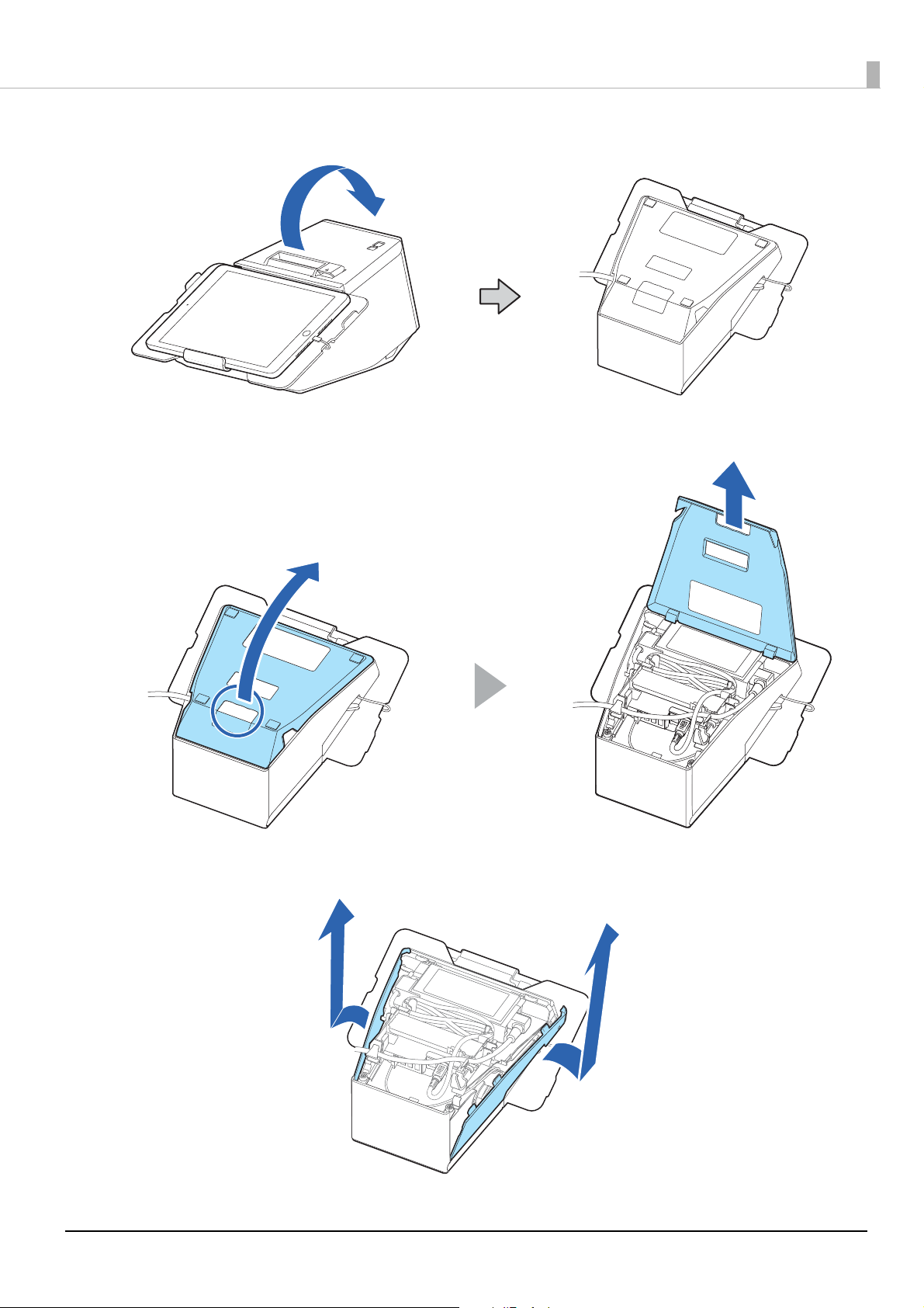
Turn over the printer.
4
Remove the bottom cover.
5
Chapter 4 Using Dedicated Optional Products
Remove the side covers.
6
73
Page 74

Chapter 4 Using Dedicated Optional Products
Remove the rear cover.
7
Attach OT-DM30SL engaging its hook with the hole in the printer, then secure it with
8
the screws.
Connect the USB cable to the USB connector, and then store the excess cable into the
9
space inside OT-DM30SL.
74
Page 75

Chapter 4 Using Dedicated Optional Products
10
11
Attach the side covers.
Attach the bottom cover.
Now mounting OT-DM30SL to the printer is finished.
75
Page 76

Chapter 4 Using Dedicated Optional Products
Adjusting the Display Brightness
The brightness of the display can be adjusted by pressing the brightness up/down buttons. There are four
brightness levels. It is set to the brightest setting by default.
Cleaning the Outer Case
When cleaning the outer surface of the customer display, make sure to turn off the printer in advance, and then
wipe dirt off with a dry cloth or a cloth slightly moistened with water.
• Never clean the product with alcohol, benzine, thinner, or other such solvents. Doing so may
damage or break the parts made of plastic and rubber.
• Rubbing the LCD screen with too much force using a dry cloth may scratch the surface.
Product Specifications
Display size 7 inch (800 x 480 pixels)
Display type TFT LCD (16.2 million colors)
Power supply USB bus power
Consumption current Operating 0.5 A (max.)
Temperature / Humidity Operating 5 to 45°C {41 to 113°F}, 10 to 90%RH, no condensation
Storage -10 to 50°C {14 to 122°F}, 10 to 90%RH, no condensation
Altitude 3,000 m or less
Dimensions 180 x 140 x 105 mm {7.1 x 5.5 x 4.1"} (W x D x H)
Weight Approx. 0.58 kg {1.28 lb}
The display functions of OT-DM30SL are the same as DM-D70. For details about the display
functions, see the user’s manual for DM-D70.
U www.epson-biz.com/?prd=dm-d70&inf=manual
76
Page 77

Chapter 4 Using Dedicated Optional Products
WARNING
This is a Class A product. In a domestic environment this product may cause radio interference in which case
the user may be required to take adequate measures.
Restriction of Use
When this product is used for applications requiring high reliability/safety, such as transportation devices
related to aviation, rail, marine, automotive, etc.; disaster prevention devices; various safety devices, etc.; or
functional/precision devices, etc.; you should use this product only after giving consideration to including failsafes and redundancies into your design to maintain safety and total system reliability. Because this product was
not intended for use in applications requiring extremely high reliability/safety, such as aerospace equipment,
main communication equipment, nuclear power control equipment, or medical equipment related to direct
medical care, etc., please make your own judgment on this product’s suitability after a full evaluation.
77
Page 78

Chapter 4 Using Dedicated Optional Products
OT-WH30SL (Wall Hanging Bracket Set)
OT-WH30SL is a dedicated bracket set for hanging this TM-m30II-SL printer on a wall.
Contents of the OT-WH30SL package
1. W
all-mount
2. Bracket
3. Four 3 x 8 screws for attaching the bracket to the printer
Using OT-WH30SL
This section describes how to install and use OT-WH30SL.
Make sure to read the cautions and notes to prevent the printer from falling from the wall.
• The package does not include screws for attaching the wall-mount to a wall. Use screws
appropriate to the type of the wall.
• Depending on the conditions during storage and shipping, some rust may form around the
edges of the wall-mount or bracket. If you find such rust, remove it with sandpaper.
Turn off the printer.
1
Disconnect the AC cable from the power outlet.
2
78
Page 79

Put the printer on a soft cloth or cushioning material.
3
Turn over the printer.
4
Chapter 4 Using Dedicated Optional Products
Attach the bracket to the printer using the included four screws.
5
Tighten the screws completely. Otherwise, the screws will get loose and may cause the
bracket or the printer to fall resulting in injury or accident.
79
Page 80

Attach the wall-mount to a wall.
84 mm
(3.31 inches)
26 mm
(1.02 inches)
26 mm
(1.02 inches)
6
• To fix the printer securely, install the wall-mount on a wall made of wood, concrete, or
• To ensure adequate strength for supporting the printer with the wall-mount, use screws
• Make sure to secure the wall-mount to the wall using the all six screw holes in the wall-
• Ensure sufficient space around the printer before attaching the wall-mount.
• Check that there is enough space for opening the roll paper cover.
Chapter 4 Using Dedicated Optional Products
metal. The thickness of the wall should be 10 mm or more.
that are appropriate to the type of the wall and have enough thread length. A screw
with 4 mm diameter and length of 12 mm or more is recommended.
mount.
Slide the bracket into the slots of the wall-mount.
7
Before mounting the printer, make sure that the wall-mount is securely attached to the
wall.
80
Page 81

Chapter 5 Advanced Usage
Advanced Usage
Software Settings
With the memory switches and customized values, which are software settings for this printer, you can set the
various functions.
For an outline of the functions, see the following section. You can make/change the settings using the methods
described in the table below, or using ESC/POS commands.
Item\Method
Receive buffer capacity
BUSY condition
Auto line feed
USB power-saving function
Release condition of receive buffer BUSY
Select paper out detector enabled for paper out signal
output
Error signal settings
Memory Switches
Pre-feed before next print
Roll paper near-end detection
Network tethering
User NV memory capacity
NV graphics memory capacity
Paper width
Print density
TM Utility for iOS,
for Android
*1
TM-m30II Utility
for Windows
Software
Setting Mode
Print speed
Thai characters print mode
Character code table defaults
International character defaults
Interface selection
Column emulation mode
Customized Values
Command execution during offline
Amount of top margin by backfeed
Interface switch waiting time
Main connection interface
Autocutting after closing cover
Paper reduction
Font A auto replacement
81
Page 82
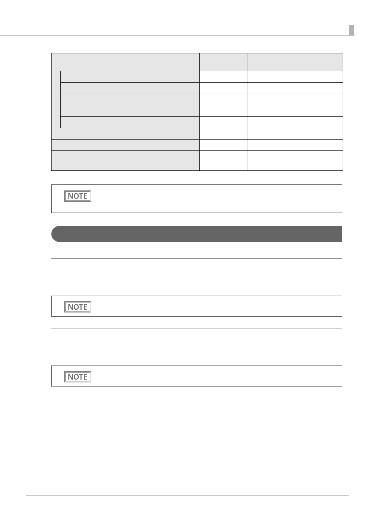
Chapter 5 Advanced Usage
Item\Method
Font B auto replacement
Font C auto replacement
Multi-tone print density
Optional buzzer
Customized Values
Batch rotate print (Upside Down)
Communication condition of USB interface
Communication condition of Bluetooth interface
Bluetooth communication interval during power
TM Utility for iOS,
for Android
TM-m30II Utility
for Windows
Software
Setting Mode
saving mode
*1 Available only with TM Utility for iOS.
• For information about how to use the software setting mode, see "Software Setting Mode" on
pa
ge 98.
• All the
settings are available using the ESC/POS commands.
Functions
Receive buffer capacity
• 4KB (initial setting)
• 45 bytes
• The receive buffer capacity for the Bluetooth interface is 64 K bytes.
• The receive buffer capacity of the USB-A Device Charging connector is 8 K bytes.
BUSY condition
• Receive buffer full/Offline (initial setting)
• Receive buffer full
In either case above, the printer enters the BUSY state after power is turned on, and when a self-test
is being run.
Auto line feed
• Normally disabled (initial setting)
• Normally enabled
82
Page 83

Chapter 5 Advanced Usage
USB power-saving function
• Disabled
• Enabled (initial setting)
The USB power-saving function is valid only when the USB interface communication condition is
set to the vendor-defined class and the system configuration is set so that the USB driver can
support the USB power-saving function.
Release condition of receive buffer BUSY
• Releases when the remaining receive buffer capacity becomes 256 bytes (initial setting)
• Releases when the remaining receive buffer capacity becomes 138 bytes
This function is enabled only when Receive buffer capacity is set to 4KB.
Select paper out detector enabled for paper out signal output
• Roll paper out detector (initial settings)
• Disabled
Error signal settings
• Enabled (initial setting)
• Disabled
Pre-feed before next print
• Disabled (initial setting)
• Enabled
• When using this function, the top margin is approximately 10.5 mm.
• This setting becomes invalid if you change the "Amount of top margin by backfeed" setting from
the initial setting (9.5mm (no backfeed)).
Roll paper near-end detection
• Disabled (initial setting)
• Enabled
Network tethering
• Disabled (initial setting)
• Enabled
83
Page 84

Chapter 5 Advanced Usage
Paper width
• 80mm (initial setting)
• 58mm
Print density
Selectable from 70% to 120% (5% increment)
Initial setting: 100%
Depending on the paper type, it is recommended to set the print density as shown in the table below for the best
print quality.
Supported papers Print density
TF50KS-EY, TF60KS-E, PD160R,
PD190R, P220AGB-1, AP45KS-ND,
AP50KS-ND, KT55PF
P5047(48) 105%
KT48FA, KT55FA, KT48PF, P5047(55) 110%
When the print density level is increased, print speed may be reduced.
100%
Print speed
Selectable from levels 1 to 13 (Slow ~ Fast)
Initial setting: level 13
Depending on print conditions, such as print duty, print head temperature, and data transmission
speed, print speed is automatically adjusted, which may cause white lines due to intermittent print
(the motor sometimes stops). To avoid this, keep the print speed constant by setting it lower.
Thai characters print mode
• Thai 1 pass (initial settings)
• Thai 3 pass
Character code table defaults
Selectable from 43 pages including user defined page
Initial setting: PC437: USA, Standard Europe
International character defaults
Selectable from 18 sets
Initial setting: USA
84
Page 85

Interface selection
• Bluetooth only
• Standard USB only
• Ethernet/Wi-Fi only
• USB-A - Device Charging only
• Enable all the interfaces (initial setting)
• Enable all the interfaces except for Bluetooth
If you want to connect a tablet and the printer via Bluetooth while charging the tablet through the
USB connector (USB-A - Device Charging), select “Bluetooth only”.
However, if you do so, the maximum supply current is limited to 0.5 A, which may not be enough
for charging some types of tablet. Please use the tablet after testing and evaluating it adequately.
Column emulation mode
• 48/35 characters mode (standard mode) (initial setting)
Chapter 5 Advanced Usage
• 42/32 characters mode
Command execution during offline
• Enabled (initial settings)
• Disabled
Amount of top margin by backfeed
• 2.0mm
• 9.5mm (no backfeed) (initial settings)
• Disable the automatic top logo setting when enabling backfeed.
• Even if the "backfeed" has been enabled, it is not performed during the self-test.
• If setting a top margin of 5 mm {0.2"} or less, confirm that no errors occur in your environment of
usage. Usage in a hot and humid environment or usage of paper that curls easily may increase
the risk of paper jams.
• When the paper is fed backward, the paper may get wrinkled or smeared due to a slack in the
roll. It is recommended to use thermal paper that has high resistance to abrasion.
• Make sure to feed the paper by at least 20 mm before moving the auto cutter. It the paper feed
length is not enough, it may cause a paper jam.
You can specify values in 0.5mm steps if you use TM-m30II Utility or TM Utility for iOS/Android.
Interface switch waiting time
Select from 1 to 10 seconds (in intervals of 1 second)
1 second (initial setting)
85
Page 86

Main connection interface
• Auto (interface that receives data first) (initial setting)
• USB
• Bluetooth
• Ethernet/Wi-Fi
• No main connection I/F
• When using this printer with multiple interfaces, make sure the interface that is always
connected to be set as the main connection.
• When using multiple interfaces, set the receive buffer capacity to 4 KB.
• You cannot use wired LAN and wireless LAN at the same time.
• When you do not use the Bluetooth function, set the Bluetooth security level to "Middle" or
"High" to prevent unauthorized access to the printer over Bluetooth. You can change the security
level by using Epson TM Utility, TM-m30II Utility, or in the Interface Setup mode.
• The displayed items vary depending on the interface configuration.
• For information about the function, see "Printing Using Multiple Interfaces" on page 29.
Chapter 5 Advanced Usage
Autocutting after closing cover
• Cuts (initial setting)
• Does not cut
Paper reduction
Extra upper space reduction
• Disabled (initial setting)
• Enabled
Extra lower space reduction
• Disabled (initial setting)
• Enabled
Line space reduction rate
• Not reduced (initial setting)
• 25%
• 50%
• 75%
Line feed reduction rate
• Not reduced (initial setting)
• 25%
• 50%
• 75%
86
Page 87

Character height reduction
• Not reduced (initial setting)
• 25% reduction of inner spacing
• 50% reduction of inner spacing
• 75% reduction of inner spacing
• 75% reduction of inner spacing and shrinking the character height
Barcode height reduction rate
• Not reduced (initial setting)
• 25%
• 50%
• 75%
• The "75% reduction of inner spacing and shrinking the character height" setting is applied to
Font A and Font B characters only. Not applied to the other font characters such as Kanji.
• No reduction is applied to blank dot lines that exist in a graphic data.
• Reduced barcodes are not guaranteed to be correctly scanned. Make sure to check whether
they are properly read by a barcode reader that is actually used.
Chapter 5 Advanced Usage
Font A auto replacement
• Does not replace (initial setting)
• Font B
• Font C
Font B auto replacement
• Does not replace (initial setting)
• Font A
• Font C
Font C auto replacement
• Does not replace (initial setting)
• Font A
• Font B
Multi-tone print density
Selectable from 70% to 100% (5% increment)
Initial setting: 100%
87
Page 88

Optional buzzer
• For information about how to connect the optional external buzzer, see "Connecting the
Optional External Buzzer" on page 60.
• When
Enables/disables
• Disabled (initial setting)
• Enabled
Buzzer frequency (Error)
• Does not sound
• Sounds 1 time
• Sounds continuously (initial setting)
Sound pattern (Autocut)
the optional external buzzer is enabled, a cash drawer cannot be used. Be sure to disable
it when you use a cash drawer.
Chapter 5 Advanced Usage
Selectable from Patterns A to E
Initial setting: Pattern A
Buzzer frequency (Autocut)
• Does not sound
• Sounds 1 time (initial setting)
Sound pattern (Pulse 1)
Selectable from Patterns A to E
Initial setting: Pattern A
Buzzer frequency (Pulse 1)
• Does not sound
• Sounds 1 time (initial setting)
Sound pattern (Pulse 2)
Selectable from Patterns A to E
Initial setting: Pattern B
Buzzer frequency (Pulse 2)
• Does not sound
• Sounds 1 time (initial setting)
Batch rotate print (Upside Down)
• Disabled (initial setting)
• Enabled
88
Page 89

Communication condition of USB interface
Class
• USB printer class (initial setting)
• USB vendor-defined class
Communication condition of Bluetooth interface
• Device name (initial setting: TM-m30II-SL_xxxxxx)
• Passkey (initial setting: 0000)
• Security (initial setting: Low)
• Auto Re-Connect with iOS device (initial setting: Enabled)
The device name is initially set to TM-m30II-SL_xxxxxx.
(xxxxxx refers to the last 6 digits of the serial number labeled on the back of your printer.)
Chapter 5 Advanced Usage
Bluetooth communication interval during power saving mode
• Level 1 (Standard) (Initial setting)
• Level 2 (Short)
By changing the setting to "Level 2 (Short)," you can shorten the time until printing begins or the
time until information is shown on the customer display connected to the printer.
However, because the communication frequency increases, the power consumption of the printer
and the host also increases.
Also, depending on the host, this setting may not be enabled, and the host-specified
communication interval may be used.
89
Page 90

Chapter 5 Advanced Usage
Change network settings
on setting computer
Setup using EpsonNet
Config
Printing the status sheet (check settings) (See "Printing a Status Sheet" on page 105.)
Method 1 Method 2 Method 3
- Use EpsonNet Config to perform
other settings
- Use EpsonNet Config ( Web version)
to perform other settings
Use arp/ping command to set
printer IP address
Finish Finish Finish
Use EpsonNet Config
(Web version) to perform settings
Network Settings
The following explains the procedure for network settings in order to connect the product to your network.
Setup methods
There are three methods for set up.
Method 1: Setup using EpsonNet Config
This method involves installing the network configuration tool, EpsonNet Config, on your computer for
setting.
As it does not require any settings in advance to allow set up, you can easily perform set up using a computer
already connected to the network.
Download EpsonNet Config from the Epson website.
Method 2: Setup using EpsonNet Config (Web version)
This method involves opening the Web application equipped in the printer from a Web browser to perform
settings.
Because you specify the printer's IP address to open it, you need to set your computer to the same network
segment as the printer.
With EpsonNet Config (Web version), you can set more items than with EpsonNet Config.
Method 3: Setup using arp/ping commands
This method involves setting the printer's IP address in the setting computer's arp/ping commands, then using
the setting tool to change the other settings.
The setting computer must be in the same segment as the printer. Also, settings can be done only when the
printer's arp+ping IP setting is set to Enable.
Use EpsonNet Config or EpsonNet Config (Web version) for settings other than the IP address.
Flow of Setup
90
Page 91

Chapter 5 Advanced Usage
Setup using EpsonNet Config
Execute EpsonNet Config, select the target printer from the displayed device list, then check and change the
settings.
If the printer is still set to factory defaults, the printer's MAC address is listed up, even if the computer does not
have the same network address.
• The initial setting uses an IP address for the printer provided by a DHCP server. Since you cannot
complete setup if there are conflicting IP addresses on the network, make sure that there are no
other devices on the network that conflict with the IP address provided by the DHCP server. If a
DHCP server is not available, a fixed IP address (192.168.192.168) is set approximately one minute
after turning on the printer. Also, if the Ethernet cable is not connected, connect the Ethernet cable
and then run this process.
• When DHCP is enabled, the provided IP address is printed automatically. However, if the Ethernet
cable is not connected, and the Wireless LAN unit is not installed, printing is not performed.
Connect the printer to the same network as the computer where you installed
1
EpsonNet Config.
Start up EpsonNet Config.
2
The tool automatically detects printers connected to the network and displays a list.
It may take up to a minute for the printer to be displayed in the list.
If it is not displayed, check that [Filter] is set to "(All)" or "Network-connected devices", then click
[Refresh]. Or, select [Tools], then [Option], and check the settings of [Search Parameters].
Select the target printer, then click [Configuration].
3
If you cannot determine the target printer from the product name or the IP address, use the MAC
address. You can check the printer's MAC address on the status sheet.
Change the printer's settings based on the network setting information you received
4
from the network administrator.
Select an item from the menu and change the setting.
Once you set the necessary items, click [Transmit].
5
The changed contents are sent to the printer and the printer settings are changed.
For details about EpsonNet Config, see the manual (operation guide) installed together with the
tool or the online help.
91
Page 92

Chapter 5 Advanced Usage
Setup using EpsonNet Config (Web version)
Follow the steps below to start up EpsonNet Config (Web version), and check or change the settings.
• When setting up using the EpsonNet Config (Web version), you need to set the network settings
for the device to the same network segment as the printer you want to connect to.
• The initial setting uses an IP address for the printer provided by a DHCP server. Since you cannot
complete setup if there are conflicting IP addresses on the network, make sure that there are no
other devices on the network that conflict with the IP address provided by the DHCP server. If a
DHCP server is not available, a fixed IP address (192.168.192.168) is set approximately one minute
after turning on the printer. Also, if the Ethernet cable is not connected, connect the Ethernet cable
and then run this process.
• When DHCP is enabled, the provided IP address is printed automatically. However, if the Ethernet
cable is not connected, and the Wireless LAN unit is not installed, printing is not performed.
Connect the setting computer and the printer to the same network.
1
Perform network settings on the computer so that it is in the same segment as the
2
printer's IP address.
Subnet mask: Same subnet mask as the printer
IP address: Same segment (same network address) as the printer, different host address
Check the values set in the printer on the status sheet.
E.g.) Printer Setting computer
Subnet mask 255.255.255.0 255.255.255.0
IP address 192.168.192.168 192.168.192.2
Start up your Web browser and input the printer's IP address into the address field.
3
E.g.) http://192.168.192.168
Under initial settings, when you access EpsonNet Config (Web version) from your browser, an
authentication warning message may be displayed.
92
Page 93

Input your user name and password on the authentication window.
Nameplate
4
• The user name is “epson”, and the default password is the serial number of the printer. You can
find the serial number by running the self-test or on the nameplate attached to the printer.
• You can change the password in the [Optional] menu, under [Password].
Chapter 5 Advanced Usage
Change the settings based on the network setting information you received from the
5
network administrator.
Select an item from [Configuration] menu and change the setting.
After changing the necessary parameters, click the [Send] button.
6
The changes are sent to the printer.
Click the [Reset] button on the Web page displayed after sending.
7
The sent contents are enabled.
Depending on the changes, such as the IP address, the connection with the setting computer may be
cut and the EpsonNet Config window may not be displayed. To reconnect, you need to set the
network settings of the setting computer to the same network segment as the printer for which
settings were changed.
Setup using arp/ping commands
You can change the printer's IP address by changing the ARP table (table of IP address and MAC addresses)
managed by the OS on the setting computer.
Check that the setting computer is connected to the network in the same segment as the printer, and that the
arp+ping IP setting for the printer is set to Enable. (The factory default is Disable.)
You can check the printer settings on the status sheet.
Delete the IP address you want to set to the printer from the ARP table.
1
arp -d (IP address)
E.g.) arp -d 192.168.0.10
93
Page 94

Chapter 5 Advanced Usage
Add the printer's MAC address and the IP address you want to set to the ARP table.
2
arp -s (IP address) (MAC address)
E.g.) arp -s 192.168.0.10 00-26-AB-7B-00-00
Execute the ping command and enable settings.
3
ping (IP address you want to set)
E.g.) ping 192.168.0.10
When a message like "Reply From 192.168.0.10: Bytes=32 Time < 10ms TTL=255" is displayed, the IP
address setting is complete.
Use EpsonNet Config or EpsonNet Config (Web version) for settings other than the IP address.
MAC Address Confirmation
You can check the printer's MAC address using the following procedures.
• Printing the status sheet
• A printer self-test (Only supported on Ethernet. For wireless, see the status sheet.)
• Using EpsonNet Config to confirm
• Using a Web browser to confirm (EpsonNet Config (Web version) function)
You can check the MAC address for network tethering using the following method.
• Printing the status sheet (MAC Address2)
94
Page 95

Chapter 5 Advanced Usage
Close the roll paper cover, and turn on the printer while pressing the Feed button.
Self-test
Briey press the Feed button. Hold down the Feed button.
Open the roll paper cover, and turn on the printer while pressing the Feed
button, and then close the roll paper cover.
Continuing the self-test
Mode selection guidance
Hexadecimal dumping
Press the Feed
button once briey
and then hold it
down.
NV Graphics
Information
Press the Feed
button twice briey
and then hold it
down.
Receipt
Enhancement
Information
Press the Feed button
three times briey
and then hold it
down.
Software Settings
Press the Feed
button four times
briey and then hold
it down.
Restore Default
Values
Press the Feed button
ve times briey and
then hold it down.
Interface Setup
Press the Feed
button six times
briey and then hold
it down.
TM-Intelligent
settings information
print
Press the Feed
button seven times
briey and then hold
it down.
Peripheral Device
Information print
Setting/Check Modes
As well as print mode, the following modes are also provided for making various printer settings and checking
items.
• Self-test mode
• NV graphics information print mode
• Receipt Enhancement information print mode
• Software settings mode
• Restore default values mode
• Interface setup mode
• Hexadecimal dumping mode
The self-test mode or hexadecimal dumping mode is selected depending on the operation performed when the
power is turned on.
NV graphic information print mode, Receipt Enhancement information print mode, Software settings mode,
and Restore default settings mode are selected depending on the Feed button operation performed during a
self-test.
95
Page 96
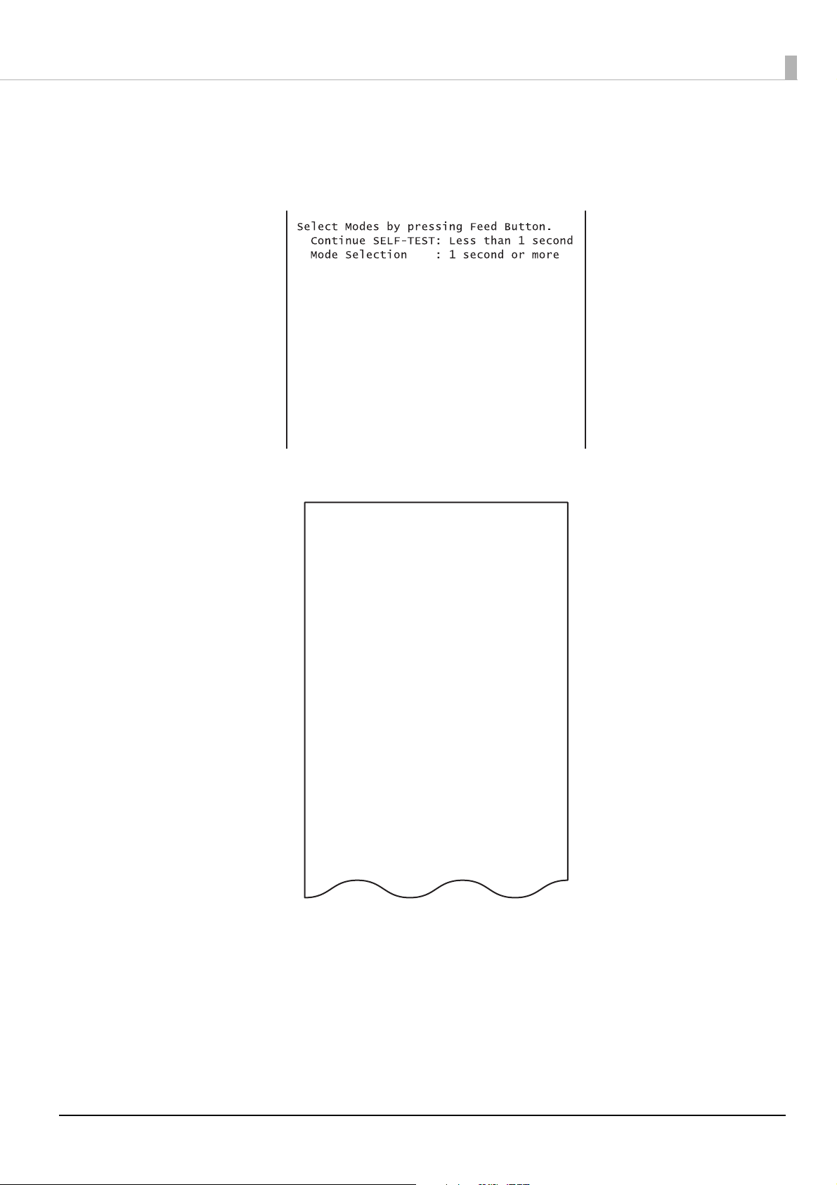
Chapter 5 Advanced Usage
Mode Selection
Modes
0: Exit and Reboot Printer
1: NV Graphics Information
2: Receipt Enhancement Information
3: Customize Value Settings
4: Restore Default Values
5: Interface Setup
6: TM-Intelligent Information
7: Peripheral Device Information
8 or more: None
Select Modes by executing following
procedure.
step 1. Press the Feed button less
than 1 second as many times
as the selected mode number.
step 2. Press Feed button for 1
second or more.
In 1 and 2, the following guidances are printed, the Paper LED flashes, and instructs the user's operations.
1. Continuing self-test guidance
2. Mode selection guidance
96
Page 97

Chapter 5 Advanced Usage
Self-test Mode
You can check the following items using the self-test.
• Product name
• Firmware version
• Product serial number
• Interface type
• Peripheral device information
• Resident fonts
• Maintenance counter information (head running length, number of times of autocutting)
Follow the steps below. You can also run the self-test using the ESC/POS commands.
Close the roll paper cover.
1
While pressing the Feed button, turn on the printer. (Hold down the Feed button
2
until printing starts.)
After printing the current print status, a Continuing self-test guidance is printed, and the Paper LED
flashes.
Briefly press the Feed button (less than one second) to continue the self-test.
3
The printer prints a rolling pattern on the roll paper, using the built-in character set.
After “*** completed ***” is printed, the printer initializes and switches to standard mode.
NV Graphics Information Print Mode
Prints the following NV graphic information registered to the printers.
• Capacity of the NV graphics
• Used capacity of the NV graphics
• Unused capacity of the NV graphics
• Number of NV graphics that are registered
• Key code, number of dots in X direction, number of dots in Y direction to be defined.
• NV graphics data
For details on NV graphics, see "NV Graphics Memory" on page 25.
Follow the steps below.
After running a self test, hold down the Feed button for at least one second, and then
1
select the Mode selection.
The Mode selection guidance is printed, and the Paper LED flashes.
97
Page 98

Chapter 5 Advanced Usage
After briefly (less than one second) pressing the Feed button once, hold it down for at
2
least one second, to print the NV graphics information.
After information printing, the Mode selection guidance is printed again.
To finish, turn off the power, or select “Exit and Reboot Printer”.
3
Receipt Enhancement Information Print Mode
You can check the following items using the R/E information mode:
• Automatic top logo setting
• Automatic bottom logo setting
• Extended settings for automatic top/bottom logo
Follow the steps below.
After running a self test, hold down the Feed button for at least one second, and then
1
select the Mode selection.
The Mode selection guidance is printed, and the Paper LED flashes.
After briefly (less than one second) pressing the Feed button twice, hold it down for
2
at least one second, to print the R/E information.
After information printing, the Mode selection guidance is printed again.
To finish, turn off the power, or select “Exit and Reboot Printer”.
3
Software Setting Mode
Set the printer's memory switches and customized values.
• Print Density
• Automatic Paper Reduction
• Enable/Disable Auto Paper Feed&Cut at cover close
• Paper Width
• Thai characters print mode
• Selection of character set
• Embedded Font Replacement
• Communication condition of USB Interface
• Print Speed
• NV Memory Capacity
• Command execution during offline
• Amount of top margin by backfeed
• Buzzer Control
98
Page 99

Chapter 5 Advanced Usage
Customize Value Settings
Modes
0: Exit
1: Print Current Settings
2: Print Density
3: Print Speed
4: Automatic Paper Reduction
5:
Auto Paper Feed&Cut at cover close
6: Paper Width
7: Character/Font Settings
8: Interface Selection
9: Interface Settings
10: Intelligent Settings
11: Command Execution (Oine)
13: Other Settings
Select Modes by executing following
procedure.
step 1. Press the Feed button less
than 1 second as many times
as the selected mode number.
step 2. Press Feed button for 1
second or more.
• Interface Settings
• Interface switch waiting time
• Main connection interface
• LED indicator when I/F starting
• Pre-feed before next print
• Enabling/disabling the roll paper near-end detector
• Enabling/disabling the Network tethering
• For details on the memory switches and customized values, see "Software Settings" on page 81.
• You can also make the software settings using the ESC/POS commands.
Follow the steps below.
After running a self test, hold down the Feed button for at least one second to enter
1
the Mode selection.
The Mode selection guidance is printed, and the Paper LED flashes.
Briefly press the Feed button three times (less than one second), hold it down for at
2
least one second to enter the Software settings mode (Customized value setting).
The Software setting mode guidance is printed, and the Paper LED flashes.
99
Page 100

Chapter 5 Advanced Usage
After briefly pressing the Feed button (less than one second) for the number of times
3
shown in the print result, hold down the button for more than one second to select
the setting items.
The setting selected as the setting item, the current settings and initial settings are printed.
Depending on the setting item, you may need to continue selecting the setting item before the
settings are printed.
For details on setting items, see "Software Settings" on page 81.
Select a setting by briefly pressing the Feed button (less than one second) for the
4
number of times applicable to the setting, and then hold down the button for more
than one second to confirm your selection.
After saving the settings, the Software setting mode guidance is printed, and the Paper LED flashes.
To close Software setting mode, turn off the printer, or select “Exit” to return to Mode
5
selection guidance, and then select “Exit and Reboot Printer”.
• To select 0 as the item number, hold down the Feed button until printing starts.
• If the button is pressed a number of times that is not displayed by the Setup guidance, the
operation is invalid and the same guidance is printed.
Restore Default Values Mode
In Restore default values mode, following values saved on NV Memory will be set back to initial settings. When
any error occurs, you can use to specify the reason.
• Memory switch
• Customized Value
• Communication Condition of USB Interface
• Status
• Character types
• Accessories
• Barcode
• Two-Dimens i ona l Sy mb ol
• Print Position
• Logo Setting
• TM-Intelligent function settings
Follow the steps below.
After running a self test, hold down the Feed button for at least one second to enter
1
the Mode selection.
The Mode selection guidance is printed, and the Paper LED flashes.
100
 Loading...