

Page 1
Peeler Model
Technical Reference Guide
410019406
Rev. G
Page 2

Page 3

TM-L90/TM-L90 Peeler Model Technical Reference Guide
Cautions
❏ No part of this document may be reproduced, stored in a retrieval system, or transmitted in any form or by any means,
electronic, mechanical, photocopying, recording, or otherwise, without the prior written permission of Seiko Epson
Corporation.
❏ The contents of this document are subject to change without notice. Please contact us for the latest information.
❏ While every precaution has been taken in the preparation of this document, Seiko Epson Corporation assumes no
responsibility for errors or omissions.
❏ Neither is any liability assumed for damages resulting from the use of the information contained herein.
❏ Neither Seiko Epson Corporation nor its affiliates shall be liable to the purchaser of this product or third parties for damages,
losses, costs, or expenses incurred by the purchaser or third parties as a result of: accident, misuse, or abuse of this product or
unauthorized modifications, repairs, or alterations to this product, or (excluding the U.S.) failure to strictly comply with Seiko
Epson Corporation’s operating and maintenance instructions.
❏ Seiko Epson Corporation shall not be liable against any damages or problems arising from the use of any options or any
consumable products other than those designated as Original Epson Products or Epson Approved Products by Seiko Epson
Corporation.
Trademarks
EPSON is a registered trademark of Seiko Epson Corporation.
Exceed Your Vision and ESC/POS are registered trademarks or trademarks of Seiko Epson Corporation.
All other trademarks are the property of their respective owners and used for identification purpose only.
ESC/POS® Command System
Epson ESC/POS is a proprietary POS printer command system that includes patented or patent-pending commands. ESC/POS is
compatible with most Epson POS printers and displays.
ESC/POS is designed to reduce the processing load on the host computer in POS environments. It comprises a set of highly
functional and efficient commands and also offers the flexibility to easily make future upgrades.
©Seiko Epson Corporation 2002-2019. All rights reserved.
3
Page 4

For Safety
Key to Symbols
The symbols in this manual are identified by their level of importance, as defined below. Read the
following carefully before handling the product.
WARNING:
You must follow warnings carefully to avoid serious bodily injury.
CAUTION:
Provides information that must be observed to prevent damage to the equipment or loss of data.
❏
Possibility of sustaining physical injuries.
❏
Possibility of causing physical damage.
❏
Possibility of causing information loss.
Note:
Provides important information and useful tips on handling the equipment.
4
Page 5

Warnings
❏
❏
❏
❏
❏
❏
❏
TM-L90/TM-L90 Peeler Model Technical Reference Guide
WARNING:
Shut down your equipment immediately if it produces smoke, a strange odor, or unusual noise.
Continued use may lead to fire or electric shock. Immediately unplug the equipment.
Only disassemble this product as described in this manual. Do not make modifications to the unit.
Tampering with this product may result in injury, fire, or electric shock.
Do not install this product or handle cables during a thunderstorm in order to avoid risk of electric
shock.
Be sure to use the specified power source. Connection to an improper power source may cause fire or
shock.
Never insert or disconnect the power plug with wet hands. Doing so may result in severe shock.
Do not allow foreign matter to fall into the equipment. Penetration by foreign objects may lead to fire or
electric shock.
If water or other liquid spills into this equipment, turn off the power switch and unplug the power cord
immediately. Continued usage may lead to fire or electric shock.
❏
Do not place multiple loads on power outlet. Overloading the outlet may lead to fire. Always supply
power directly from a standard domestic power outlet.
❏
Handle the power cord with care. Improper handling may lead to fire or electric shock.
• Do not modify or attempt to repair the cord.
• Do not place any heavy object on top of the cord.
• Avoid excessive bending, twisting, and pulling.
• Do not place the cord near heating equipment.
• Check that the plug is clean before plugging it in.
• Be sure to push the plug all the way in.
5
Page 6

Cautions
❏
❏
❏
❏
❏
❏
CAUTION:
Do not connect cables in ways other than those mentioned in this manual. Different connections may
cause equipment damage and burning.
Be sure to set this equipment on a firm, stable horizontal surface. Product may break or cause injury if it
falls.
Do not use in locations subject to high humidity or dust levels. Excessive humidity and dust may cause
equipment damage, fire, or shock.
Do not place heavy objects on top of this equipment. Never stand or lean on this equipment. Equipment
may fall or collapse, causing breakage and possible injury.
To ensure safety, unplug this equipment prior to leaving it unused for an extended period.
Take care not to injure your fingers on the manual cutter
• When you remove printed paper
• When you perform other operations such as loading/replacing roll paper
❏
Do not open the roll paper cover without taking the necessary precautions, as this can result in injury
from the autocutter fixed blade.
❏
Do not use aerosol sprayers containing flammable gas inside or around this product. Doing so may
cause fire.
❏
Make sure to avoid bumping or otherwise exposing the printer to strong impact during operation.
Restriction of Use
When this product is used for applications requiring high reliability/safety such as transportation devices
related to aviation, rail, marine, automotive etc.; disaster prevention devices; various safety devices etc; or
functional/precision devices etc, you should use this product only after giving consideration to including
fail-safes and redundancies into your design to maintain safety and total system reliability. Because this
product was not intended for use in applications requiring extremely high reliability/safety such as
aerospace equipment, main communication equipment, nuclear power control equipment, or medical
equipment related to direct medical care etc, please make your own judgment on this product’s suitability
after a full evaluation.
Modular Connector
Use the modular connectors specifically designed for the cash drawer for this product. Do not connect
these connectors to an ordinary telephone line.
6
Page 7

TM-L90/TM-L90 Peeler Model Technical Reference Guide
About This Manual
Aim of the Manual
This manual was created to provide all information necessary for system planning, design, installations
and application of the printer for designers and developers of POS systems.
Manual Content
The manual is made up of the following sections:
Chapter 1 Product Overview
Chapter 2 Setup
Chapter 3 Connecting to the Host Computer and Options
Chapter 4 Setting/Checking Modes
Chapter 5 Application Development Information
Chapter 6 ESC/POS Command-Related Information
Chapter 7 Handling
Appendix Setting items for Memory Switch Setting Mode
Specifications
Character Code Table
Related Documentation
The following documents also relate to the TM-L90 / TM-L90 Peeler Model.
Name of document Description
TM-L90 User's Manual (for TM-L90)
TM-L90 with Peeler User's Manual (for TM-L90 Peeler other
than 39* models)
TM-L90 Peeler Model User's Manual (for TM-L90 Peeler 39*
models)
ESC/POS Command Reference Provides detailed ESC/POS command information.
Comes with the printer.
Provides information to enable POS operators to use
the printer safely and correctly.
7
Page 8

For Safety . . . . . . . . . . . . . . . . . . . . . . . . . . . . . . . . . . . . . . . . . . . . . . . . . . . . . . . . . . . . . . . . . . . . . . . . . . . . . . . . . . . . . . . . . . . . . . . . . . . . 4
Key to Symbols . . . . . . . . . . . . . . . . . . . . . . . . . . . . . . . . . . . . . . . . . . . . . . . . . . . . . . . . . . . . . . . . . . . . . . . . . . . . . . . . . . . . . . . . . . 4
Warnings . . . . . . . . . . . . . . . . . . . . . . . . . . . . . . . . . . . . . . . . . . . . . . . . . . . . . . . . . . . . . . . . . . . . . . . . . . . . . . . . . . . . . . . . . . . . . . . 5
Cautions . . . . . . . . . . . . . . . . . . . . . . . . . . . . . . . . . . . . . . . . . . . . . . . . . . . . . . . . . . . . . . . . . . . . . . . . . . . . . . . . . . . . . . . . . . . . . . . . 6
Restriction of Use . . . . . . . . . . . . . . . . . . . . . . . . . . . . . . . . . . . . . . . . . . . . . . . . . . . . . . . . . . . . . . . . . . . . . . . . . . . . . . . . . . . . . . . . . . . . . 6
Modular Connector . . . . . . . . . . . . . . . . . . . . . . . . . . . . . . . . . . . . . . . . . . . . . . . . . . . . . . . . . . . . . . . . . . . . . . . . . . . . . . . . . . . . . . . . . . . 6
About This Manual . . . . . . . . . . . . . . . . . . . . . . . . . . . . . . . . . . . . . . . . . . . . . . . . . . . . . . . . . . . . . . . . . . . . . . . . . . . . . . . . . . . . . . . . . . . 7
Aim of the Manual . . . . . . . . . . . . . . . . . . . . . . . . . . . . . . . . . . . . . . . . . . . . . . . . . . . . . . . . . . . . . . . . . . . . . . . . . . . . . . . . . . . . . . . 7
Manual Content . . . . . . . . . . . . . . . . . . . . . . . . . . . . . . . . . . . . . . . . . . . . . . . . . . . . . . . . . . . . . . . . . . . . . . . . . . . . . . . . . . . . . . . . . . 7
Related Documentation . . . . . . . . . . . . . . . . . . . . . . . . . . . . . . . . . . . . . . . . . . . . . . . . . . . . . . . . . . . . . . . . . . . . . . . . . . . . . . . . . . . 7
Chapter 1 Product Overview
Product Structure . . . . . . . . . . . . . . . . . . . . . . . . . . . . . . . . . . . . . . . . . . . . . . . . . . . . . . . . . . . . . . . . . . . . . . . . . . . . . . . . . . . . . . . . . . . . . 11
Models . . . . . . . . . . . . . . . . . . . . . . . . . . . . . . . . . . . . . . . . . . . . . . . . . . . . . . . . . . . . . . . . . . . . . . . . . . . . . . . . . . . . . . . . . . . . . . . . . . 11
Accessories . . . . . . . . . . . . . . . . . . . . . . . . . . . . . . . . . . . . . . . . . . . . . . . . . . . . . . . . . . . . . . . . . . . . . . . . . . . . . . . . . . . . . . . . . . . . . . 11
Option . . . . . . . . . . . . . . . . . . . . . . . . . . . . . . . . . . . . . . . . . . . . . . . . . . . . . . . . . . . . . . . . . . . . . . . . . . . . . . . . . . . . . . . . . . . . . . . . . . 12
Name and Description of Each Part . . . . . . . . . . . . . . . . . . . . . . . . . . . . . . . . . . . . . . . . . . . . . . . . . . . . . . . . . . . . . . . . . . . . . . . . . . . . . 13
Part Names (TM-L90) . . . . . . . . . . . . . . . . . . . . . . . . . . . . . . . . . . . . . . . . . . . . . . . . . . . . . . . . . . . . . . . . . . . . . . . . . . . . . . . . . . . . 13
Part Names (TM-L90 Peeler Model) . . . . . . . . . . . . . . . . . . . . . . . . . . . . . . . . . . . . . . . . . . . . . . . . . . . . . . . . . . . . . . . . . . . . . . . . 14
Paper FEED button inside the printer . . . . . . . . . . . . . . . . . . . . . . . . . . . . . . . . . . . . . . . . . . . . . . . . . . . . . . . . . . . . . . . . . . . . . . . 15
Control Panel . . . . . . . . . . . . . . . . . . . . . . . . . . . . . . . . . . . . . . . . . . . . . . . . . . . . . . . . . . . . . . . . . . . . . . . . . . . . . . . . . . . . . . . . . . . . 15
Power Switch . . . . . . . . . . . . . . . . . . . . . . . . . . . . . . . . . . . . . . . . . . . . . . . . . . . . . . . . . . . . . . . . . . . . . . . . . . . . . . . . . . . . . . . . . . . . 17
Power Switch Cover . . . . . . . . . . . . . . . . . . . . . . . . . . . . . . . . . . . . . . . . . . . . . . . . . . . . . . . . . . . . . . . . . . . . . . . . . . . . . . . . . . . . . . 18
Mode Switch (TM-L90 Peeler Model Only) . . . . . . . . . . . . . . . . . . . . . . . . . . . . . . . . . . . . . . . . . . . . . . . . . . . . . . . . . . . . . . . . . . 19
Connectors . . . . . . . . . . . . . . . . . . . . . . . . . . . . . . . . . . . . . . . . . . . . . . . . . . . . . . . . . . . . . . . . . . . . . . . . . . . . . . . . . . . . . . . . . . . . . . 20
Chapter 2 Setup
Setup Flow . . . . . . . . . . . . . . . . . . . . . . . . . . . . . . . . . . . . . . . . . . . . . . . . . . . . . . . . . . . . . . . . . . . . . . . . . . . . . . . . . . . . . . . . . . . . . . . . . . . 21
Installation Procedures . . . . . . . . . . . . . . . . . . . . . . . . . . . . . . . . . . . . . . . . . . . . . . . . . . . . . . . . . . . . . . . . . . . . . . . . . . . . . . . . . . . . . . . . 22
Precaution For Installation . . . . . . . . . . . . . . . . . . . . . . . . . . . . . . . . . . . . . . . . . . . . . . . . . . . . . . . . . . . . . . . . . . . . . . . . . . . . . . . . 22
Instructions for Installation . . . . . . . . . . . . . . . . . . . . . . . . . . . . . . . . . . . . . . . . . . . . . . . . . . . . . . . . . . . . . . . . . . . . . . . . . . . . . . . . 23
Adjusting Roll Paper Near-End Detection Position . . . . . . . . . . . . . . . . . . . . . . . . . . . . . . . . . . . . . . . . . . . . . . . . . . . . . . . . . . . . . . . . 25
With TM-L90 . . . . . . . . . . . . . . . . . . . . . . . . . . . . . . . . . . . . . . . . . . . . . . . . . . . . . . . . . . . . . . . . . . . . . . . . . . . . . . . . . . . . . . . . . . . . 25
With the TM-L90 Peeler Model . . . . . . . . . . . . . . . . . . . . . . . . . . . . . . . . . . . . . . . . . . . . . . . . . . . . . . . . . . . . . . . . . . . . . . . . . . . . 29
Connecting AC adapter (PS-180) . . . . . . . . . . . . . . . . . . . . . . . . . . . . . . . . . . . . . . . . . . . . . . . . . . . . . . . . . . . . . . . . . . . . . . . . . . . . . . . 33
Attaching AC adapter . . . . . . . . . . . . . . . . . . . . . . . . . . . . . . . . . . . . . . . . . . . . . . . . . . . . . . . . . . . . . . . . . . . . . . . . . . . . . . . . . . . . . 33
Caution about AC adapter and Supply Voltage . . . . . . . . . . . . . . . . . . . . . . . . . . . . . . . . . . . . . . . . . . . . . . . . . . . . . . . . . . . . . . . 34
Autocutter Settings (TM-L90 only) . . . . . . . . . . . . . . . . . . . . . . . . . . . . . . . . . . . . . . . . . . . . . . . . . . . . . . . . . . . . . . . . . . . . . . . . . . . . . . 35
Cautions on the Lengths of the Receipts/Labels to Issue . . . . . . . . . . . . . . . . . . . . . . . . . . . . . . . . . . . . . . . . . . . . . . . . . . . . . . . . 35
Setting Procedure . . . . . . . . . . . . . . . . . . . . . . . . . . . . . . . . . . . . . . . . . . . . . . . . . . . . . . . . . . . . . . . . . . . . . . . . . . . . . . . . . . . . . . . . 36
Setting Roll Paper Width . . . . . . . . . . . . . . . . . . . . . . . . . . . . . . . . . . . . . . . . . . . . . . . . . . . . . . . . . . . . . . . . . . . . . . . . . . . . . . . . . . . . . . 38
DIP Switch Settings . . . . . . . . . . . . . . . . . . . . . . . . . . . . . . . . . . . . . . . . . . . . . . . . . . . . . . . . . . . . . . . . . . . . . . . . . . . . . . . . . . . . . . . . . . . 40
Memory Switch Settings . . . . . . . . . . . . . . . . . . . . . . . . . . . . . . . . . . . . . . . . . . . . . . . . . . . . . . . . . . . . . . . . . . . . . . . . . . . . . . . . . . . . . . . 42
Memory switches of TM-L90 . . . . . . . . . . . . . . . . . . . . . . . . . . . . . . . . . . . . . . . . . . . . . . . . . . . . . . . . . . . . . . . . . . . . . . . . . . . . . . 43
Memory switches of TM-L90 Peeler Model . . . . . . . . . . . . . . . . . . . . . . . . . . . . . . . . . . . . . . . . . . . . . . . . . . . . . . . . . . . . . . . . . . 48
Paper Loading Method . . . . . . . . . . . . . . . . . . . . . . . . . . . . . . . . . . . . . . . . . . . . . . . . . . . . . . . . . . . . . . . . . . . . . . . . . . . . . . . . . . . . . . . . 53
With TM-L90 . . . . . . . . . . . . . . . . . . . . . . . . . . . . . . . . . . . . . . . . . . . . . . . . . . . . . . . . . . . . . . . . . . . . . . . . . . . . . . . . . . . . . . . . . . . . 53
With the TM-L90 Peeler Model . . . . . . . . . . . . . . . . . . . . . . . . . . . . . . . . . . . . . . . . . . . . . . . . . . . . . . . . . . . . . . . . . . . . . . . . . . . . 54
Setting Paper Layout . . . . . . . . . . . . . . . . . . . . . . . . . . . . . . . . . . . . . . . . . . . . . . . . . . . . . . . . . . . . . . . . . . . . . . . . . . . . . . . . . . . . . . 57
Clearing Paper Layout Setting . . . . . . . . . . . . . . . . . . . . . . . . . . . . . . . . . . . . . . . . . . . . . . . . .
Chapter 3
Connecting the Cable . . . . . . . . . . . . . . . . . . . . . . . . . . . . . . . . . . . . . . . . . . . . . . . . . . . . . . . . . . . . . . . . . . . . . . . . . . . . . . . . . . . . . . . . . 63
Connecting to the Host Computer . . . . . . . . . . . . . . . . . . . . . . . . . . . . . . . . . . . . . . . . . . . . . . . . . . . . . . . . . . . . . . . . . . . . . . . . . . . . . . 64
Connecting to the Host Computer and Options
With the RS-232C Interface . . . . . . . . . . . . . . . . . . . . . . . . . . . . . . . . . . . . . . . . . . . . . . . . . . . . . . . . . . . . . . . . . . . . . . . . . . . . . . . . 64
. . . . . . . . . . . . . . . . . . . . . . . . . . . . . 62
8
Page 9

TM-L90/TM-L90 Peeler Model Technical Reference Guide
With the Parallel (IEEE1284) Interface . . . . . . . . . . . . . . . . . . . . . . . . . . . . . . . . . . . . . . . . . . . . . . . . . . . . . . . . . . . . . . . . . . . . . . 67
With the USB Interface . . . . . . . . . . . . . . . . . . . . . . . . . . . . . . . . . . . . . . . . . . . . . . . . . . . . . . . . . . . . . . . . . . . . . . . . . . . . . . . . . . . . 68
With the Ethernet Interface (TM-L90 only) . . . . . . . . . . . . . . . . . . . . . . . . . . . . . . . . . . . . . . . . . . . . . . . . . . . . . . . . . . . . . . . . . . 70
With the Wireless LAN Interface . . . . . . . . . . . . . . . . . . . . . . . . . . . . . . . . . . . . . . . . . . . . . . . . . . . . . . . . . . . . . . . . . . . . . . . . . . . 71
Connecting the Cash Drawer . . . . . . . . . . . . . . . . . . . . . . . . . . . . . . . . . . . . . . . . . . . . . . . . . . . . . . . . . . . . . . . . . . . . . . . . . . . . . . . . . . . 72
Setting the internal buzzer (for models with an internal buzzer) . . . . . . . . . . . . . . . . . . . . . . . . . . . . . . . . . . . . . . . . . . . . . . . . . 73
Chapter 4 Setting/Checking Modes
Setting/Checking Modes of TM-L90 4** models, TM-L90 Peeler 39* models . . . . . . . . . . . . . . . . . . . . . . . . . . . . . . . . . . . . . . . . . . 75
Self-test Mode . . . . . . . . . . . . . . . . . . . . . . . . . . . . . . . . . . . . . . . . . . . . . . . . . . . . . . . . . . . . . . . . . . . . . . . . . . . . . . . . . . . . . . . . . . . . 76
NV Graphics Information Print Mode . . . . . . . . . . . . . . . . . . . . . . . . . . . . . . . . . . . . . . . . . . . . . . . . . . . . . . . . . . . . . . . . . . . . . . . 77
Memory Switch Setting Mode . . . . . . . . . . . . . . . . . . . . . . . . . . . . . . . . . . . . . . . . . . . . . . . . . . . . . . . . . . . . . . . . . . . . . . . . . . . . . . 78
Hexadecimal Dump Mode . . . . . . . . . . . . . . . . . . . . . . . . . . . . . . . . . . . . . . . . . . . . . . . . . . . . . . . . . . . . . . . . . . . . . . . . . . . . . . . . . 79
Setting/Checking Modes of TM-L90 other than 4** models, TM-L90 Peeler other than 39* models . . . . . . . . . . . . . . . . . . . . . .80
Self-test Mode . . . . . . . . . . . . . . . . . . . . . . . . . . . . . . . . . . . . . . . . . . . . . . . . . . . . . . . . . . . . . . . . . . . . . . . . . . . . . . . . . . . . . . . . . . . . 80
Memory Switch Setting Mode . . . . . . . . . . . . . . . . . . . . . . . . . . . . . . . . . . . . . . . . . . . . . . . . . . . . . . . . . . . . . . . . . . . . . . . . . . . . . . 81
Hexadecimal Dump Mode . . . . . . . . . . . . . . . . . . . . . . . . . . . . . . . . . . . . . . . . . . . . . . . . . . . . . . . . . . . . . . . . . . . . . . . . . . . . . . . . . 82
Chapter 5 Application Development Information
Introduction of Control Methods . . . . . . . . . . . . . . . . . . . . . . . . . . . . . . . . . . . . . . . . . . . . . . . . . . . . . . . . . . . . . . . . . . . . . . . . . . . . . . . 83
Windows Driver (EPSON Advanced Printer Driver) . . . . . . . . . . . . . . . . . . . . . . . . . . . . . . . . . . . . . . . . . . . . . . . . . . . . . . . . . . 83
EPSON OPOS ADK . . . . . . . . . . . . . . . . . . . . . . . . . . . . . . . . . . . . . . . . . . . . . . . . . . . . . . . . . . . . . . . . . . . . . . . . . . . . . . . . . . . . . . 85
ESC/POS Commands . . . . . . . . . . . . . . . . . . . . . . . . . . . . . . . . . . . . . . . . . . . . . . . . . . . . . . . . . . . . . . . . . . . . . . . . . . . . . . . . . . . . . 88
Various Utilities . . . . . . . . . . . . . . . . . . . . . . . . . . . . . . . . . . . . . . . . . . . . . . . . . . . . . . . . . . . . . . . . . . . . . . . . . . . . . . . . . . . . . . . . . . 89
Sensors . . . . . . . . . . . . . . . . . . . . . . . . . . . . . . . . . . . . . . . . . . . . . . . . . . . . . . . . . . . . . . . . . . . . . . . . . . . . . . . . . . . . . . . . . . . . . . . . . . . . . . 89
Paper Sensors . . . . . . . . . . . . . . . . . . . . . . . . . . . . . . . . . . . . . . . . . . . . . . . . . . . . . . . . . . . . . . . . . . . . . . . . . . . . . . . . . . . . . . . . . . . . 89
Printer Cover Sensor . . . . . . . . . . . . . . . . . . . . . . . . . . . . . . . . . . . . . . . . . . . . . . . . . . . . . . . . . . . . . . . . . . . . . . . . . . . . . . . . . . . . . . 90
Label Peeling Sensor (Peeler Specification Only) . . . . . . . . . . . . . . . . . . . . . . . . . . . . . . . . . . . . . . . . . . . . . . . . . . . . . . . . . . . . . . 92
Barcode Printing . . . . . . . . . . . . . . . . . . . . . . . . . . . . . . . . . . . . . . . . . . . . . . . . . . . . . . . . . . . . . . . . . . . . . . . . . . . . . . . . . . . . . . . . . . . . . . 92
CODE 128 Barcode . . . . . . . . . . . . . . . . . . . . . . . . . . . . . . . . . . . . . . . . . . . . . . . . . . . . . . . . . . . . . . . . . . . . . . . . . . . . . . . . . . . . . . . . . . . 93
Precautions for Two-Dimensional Code Printing . . . . . . . . . . . . . . . . . . . . . . . . . . . . . . . . . . . . . . . . . . . . . . . . . . . . . . . . . . . . . . . . . 97
NV Memory . . . . . . . . . . . . . . . . . . . . . . . . . . . . . . . . . . . . . . . . . . . . . . . . . . . . . . . . . . . . . . . . . . . . . . . . . . . . . . . . . . . . . . . . . . . . . . . . . 97
FAQ List . . . . . . . . . . . . . . . . . . . . . . . . . . . . . . . . . . . . . . . . . . . . . . . . . . . . . . . . . . . . . . . . . . . . . . . . . . . . . . . . . . . . . . . . . . . . . . . . . . . . . 98
Chapter 6 ESC/POS Command-Related Information
TM Printer Operation Performed When Power Switch is Disabled . . . . . . . . . . . . . . . . . . . . . . . . . . . . . . . . . . . . . . . . . . . . . . . . . . 101
Power Switch-Related User Operation List . . . . . . . . . . . . . . . . . . . . . . . . . . . . . . . . . . . . . . . . . . . . . . . . . . . . . . . . . . . . . . . . . . . 102
Power Off Control by the Host . . . . . . . . . . . . . . . . . . . . . . . . . . . . . . . . . . . . . . . . . . . . . . . . . . . . . . . . . . . . . . . . . . . . . . . . . . . . . 102
Head Divided Control . . . . . . . . . . . . . . . . . . . . . . . . . . . . . . . . . . . . . . . . . . . . . . . . . . . . . . . . . . . . . . . . . . . . . . . . . . . . . . . . . . . . . . . . . 102
Control After Paper Cut . . . . . . . . . . . . . . . . . . . . . . . . . . . . . . . . . . . . . . . . . . . . . . . . . . . . . . . . . . . . . . . . . . . . . . . . . . . . . . . . . . . . . . . 103
NV Memory . . . . . . . . . . . . . . . . . . . . . . . . . . . . . . . . . . . . . . . . . . . . . . . . . . . . . . . . . . . . . . . . . . . . . . . . . . . . . . . . . . . . . . . . . . . . . . . . . 103
Customizing Printer . . . . . . . . . . . . . . . . . . . . . . . . . . . . . . . . . . . . . . . . . . . . . . . . . . . . . . . . . . . . . . . . . . . . . . . . . . . . . . . . . . . . . . . . . . . 104
Printer Initial Setting Up . . . . . . . . . . . . . . . . . . . . . . . . . . . . . . . . . . . . . . . . . . . . . . . . . . . . . . . . . . . . . . . . . . . . . . . . . . . . . . . . . . 104
Changing Command Default Values . . . . . . . . . . . . . . . . . . . . . . . . . . . . . . . . . . . . . . . . . . . . . . . . . . . . . . . . . . . . . . . . . . . . . . . . 104
Using the NV Memory . . . . . . . . . . . . . . . . . . . . . . . . . . . . . . . . . . . . . . . . . . . . . . . . . . . . . . . . . . . . . . . . . . . . . . . . . . . . . . . . . . . . 104
Printer Status . . . . . . . . . . . . . . . . . . . . . . . . . . . . . . . . . . . . . . . . . . . . . . . . . . . . . . . . . . . . . . . . . . . . . . . . . . . . . . . . . . . . . . . . . . . . . . . . . 104
Chapter 7 Handling
Maintenance . . . . . . . . . . . . . . . . . . . . . . . . . . . . . . . . . . . . . . . . . . . . . . . . . . . . . . . . . . . . . . . . . . . . . . . . . . . . . . . . . . . . . . . . . . . . . . . . . 105
Cleaning the autocutter (TM-L90 only) . . . . . . . . . . . . . . . . . . . . . . . . . . . . . . . . . . . . . . . . . . . . . . . . . . . . . . . . . . . . . . . . . . . . . . 105
Print Head Cleaning
Cleaning the peeler (TM-L90 Peeler Model only) . . . . . . . . . . . . . . . . . . . . . . . . . . . . . . . . . . . . . . . . . . . . . . . . . . . . . . . . . . . . . 108
Troubleshooting . . . . . . . . . . . . . . . . . . . . . . . . . . . . . . . . . . . . . . . . . . . . . . . . . . . . . . . . . . . . . . . . . . . . . . . . . . . . . . . . . . . . . . . . . . . . . . 109
Panel LED and Error Status . . . . . . . . . . . . . . . . . . . . . . . . . . . . . . . . . . . . . . . . . . . . . . . . . . . . . . . . . . . . . . . . . . . . . . . . . . . . . . . . 109
The autocutter is jammed or the roll paper cover will not open (TM-L90 only) . . . . . . . . . . . . . . . . . . . . . . . . . . . . . . . . . . . . 116
. . . . . . . . . . . . . . . . . . . . . . . . . . . . . . . . . . . . . . . . . . . . . . . . . . . . . . . . . . . . . . . . . . . . . . . . . . . . . . . . . . . . . . 107
9
Page 10

When a paper jam occurs (TM-L90 Peeler Model) . . . . . . . . . . . . . . . . . . . . . . . . . . . . . . . . . . . . . . . . . . . . . . . . . . . . . . . . . . . . 117
The printer became inoperative after you change the interface reset signal in the memory switch setting mode . . . . . . . . 117
Shipping Procedures . . . . . . . . . . . . . . . . . . . . . . . . . . . . . . . . . . . . . . . . . . . . . . . . . . . . . . . . . . . . . . . . . . . . . . . . . . . . . . . . . . . . . . . . . . 118
Appendix Appendix
Setting items for Memory Switch Setting Mode . . . . . . . . . . . . . . . . . . . . . . . . . . . . . . . . . . . . . . . . . . . . . . . . . . . . . . . . . . . . . . . . . . . 119
Setting items of TM-L90 4** models . . . . . . . . . . . . . . . . . . . . . . . . . . . . . . . . . . . . . . . . . . . . . . . . . . . . . . . . . . . . . . . . . . . . . . . . 119
Setting items of TM-L90 other than 4** models . . . . . . . . . . . . . . . . . . . . . . . . . . . . . . . . . . . . . . . . . . . . . . . . . . . . . . . . . . . . . . . 123
Setting items of TM-L90 Peeler 39* models . . . . . . . . . . . . . . . . . . . . . . . . . . . . . . . . . . . . . . . . . . . . . . . . . . . . . . . . . . . . . . . . . . 124
Setting items of TM-L90 Peeler other than 39* models . . . . . . . . . . . . . . . . . . . . . . . . . . . . . . . . . . . . . . . . . . . . . . . . . . . . . . . . . 126
Product Specifications . . . . . . . . . . . . . . . . . . . . . . . . . . . . . . . . . . . . . . . . . . . . . . . . . . . . . . . . . . . . . . . . . . . . . . . . . . . . . . . . . . . . . . . . . 128
Product Specifications . . . . . . . . . . . . . . . . . . . . . . . . . . . . . . . . . . . . . . . . . . . . . . . . . . . . . . . . . . . . . . . . . . . . . . . . . . . . . . . . . . . . 128
Print Specifications . . . . . . . . . . . . . . . . . . . . . . . . . . . . . . . . . . . . . . . . . . . . . . . . . . . . . . . . . . . . . . . . . . . . . . . . . . . . . . . . . . . . . . 131
Reliability . . . . . . . . . . . . . . . . . . . . . . . . . . . . . . . . . . . . . . . . . . . . . . . . . . . . . . . . . . . . . . . . . . . . . . . . . . . . . . . . . . . . . . . . . . . . . . . 132
Character Specifications . . . . . . . . . . . . . . . . . . . . . . . . . . . . . . . . . . . . . . . . . . . . . . . . . . . . . . . . . . . . . . . . . . . . . . . . . . . . . . . . . . 135
Paper Feed Specifications . . . . . . . . . . . . . . . . . . . . . . . . . . . . . . . . . . . . . . . . . . . . . . . . . . . . . . . . . . . . . . . . . . . . . . . . . . . . . . . . . 136
Paper Specifications . . . . . . . . . . . . . . . . . . . . . . . . . . . . . . . . . . . . . . . . . . . . . . . . . . . . . . . . . . . . . . . . . . . . . . . . . . . . . . . . . . . . . . 136
Printing Area . . . . . . . . . . . . . . . . . . . . . . . . . . . . . . . . . . . . . . . . . . . . . . . . . . . . . . . . . . . . . . . . . . . . . . . . . . . . . . . . . . . . . . . . . . . . 137
Printing Position in Relation to Cutter Position (TM-L90) . . . . . . . . . . . . . . . . . . . . . . . . . . . . . . . . . . . . . . . . . . . . . . . . . . . . . 139
Printing Position, Peeling Position, Manual Cutter Position (TM-L90 Peeler Model) . . . . . . . . . . . . . . . . . . . . . . . . . . . . . . 140
Overview of External Dimensions . . . . . . . . . . . . . . . . . . . . . . . . . . . . . . . . . . . . . . . . . . . . . . . . . . . . . . . . . . . . . . . . . . . . . . . . . . 141
Interface And Connectors . . . . . . . . . . . . . . . . . . . . . . . . . . . . . . . . . . . . . . . . . . . . . . . . . . . . . . . . . . . . . . . . . . . . . . . . . . . . . . . . . . . . . . 144
RS-232 Serial Interface . . . . . . . . . . . . . . . . . . . . . . . . . . . . . . . . . . . . . . . . . . . . . . . . . . . . . . . . . . . . . . . . . . . . . . . . . . . . . . . . . . . . 144
IEEE1284 Parallel Interface . . . . . . . . . . . . . . . . . . . . . . . . . . . . . . . . . . . . . . . . . . . . . . . . . . . . . . . . . . . . . . . . . . . . . . . . . . . . . . . . 147
Option Specifications . . . . . . . . . . . . . . . . . . . . . . . . . . . . . . . . . . . . . . . . . . . . . . . . . . . . . . . . . . . . . . . . . . . . . . . . . . . . . . . . . . . . . . . . . 151
PS-180 . . . . . . . . . . . . . . . . . . . . . . . . . . . . . . . . . . . . . . . . . . . . . . . . . . . . . . . . . . . . . . . . . . . . . . . . . . . . . . . . . . . . . . . . . . . . . . . . . . 151
Consumable Specifications . . . . . . . . . . . . . . . . . . . . . . . . . . . . . . . . . . . . . . . . . . . . . . . . . . . . . . . . . . . . . . . . . . . . . . . . . . . . . . . . . . . . . 153
Paper Specification . . . . . . . . . . . . . . . . . . . . . . . . . . . . . . . . . . . . . . . . . . . . . . . . . . . . . . . . . . . . . . . . . . . . . . . . . . . . . . . . . . . . . . . 153
Specified Roll Paper . . . . . . . . . . . . . . . . . . . . . . . . . . . . . . . . . . . . . . . . . . . . . . . . . . . . . . . . . . . . . . . . . . . . . . . . . . . . . . . . . . . . . . 155
Requirements for Receipt Paper . . . . . . . . . . . . . . . . . . . . . . . . . . . . . . . . . . . . . . . . . . . . . . . . . . . . . . . . . . . . . . . . . . . . . . . . . . . . 156
Requirements for Die-Cut Label Paper . . . . . . . . . . . . . . . . . . . . . . . . . . . . . . . . . . . . . . . . . . . . . . . . . . . . . . . . . . . . . . . . . . . . . . 157
Requirements for Continuous Label Paper . . . . . . . . . . . . . . . . . . . . . . . . . . . . . . . . . . . . . . . . . . . . . . . . . . . . . . . . . . . . . . . . . . . 162
Notes on Paper Handling . . . . . . . . . . . . . . . . . . . . . . . . . . . . . . . . . . . . . . . . . . . . . . . . . . . . . . . . . . . . . . . . . . . . . . . . . . . . . . . . . . 164
Character Code Table . . . . . . . . . . . . . . . . . . . . . . . . . . . . . . . . . . . . . . . . . . . . . . . . . . . . . . . . . . . . . . . . . . . . . . . . . . . . . . . . . . . . . . . . . 164
10
Page 11

TM-L90/TM-L90 Peeler Model Technical Reference Guide
Chapter 1
Product Overview
1.1 Product Structure
1.1.1 Models
❏
Model
Peeler unit Power switch
TM-L90 other than 4** models not mounted non-locking push button
TM-L90 4** models not mounted locker switch
TM-L90 Peeler other than 39* models mounted non-locking push button
TM-L90 Peeler 39* models mounted locker switch
❏
Interface
• Serial (RS-232C)
• Parallel (IEEE-1284 standard)
• USB (USB2.0)
• Ethernet (10BASE-T/100BASE-T)
• Wireless LAN (IEEE802.11a/b/g/n for TM-L90 4** models, TM-L90 Peeler 39* models)
• Wireless LAN (IEEE802.11b for the other models)
TM-L90 4** models and TM-L90 Peeler 39* models may have the build-in-USB.
1.1.2 Accessories
TM-L90
❏
Start Here
❏
Label roll paper
❏
Manual CD
❏
Power switch cover
❏
Control panel label used for horizontal installation
❏
Paper exit guide for horizontal installation
❏
Roll paper spacer
Product Overview 11
Page 12

❏
Screw for installation of the roll paper spacer
❏
Wire saddle*
❏
AC adapter*
❏
AC cable*
* May not be included depending on the printer model.
TM-L90 Peeler Model
❏
Start Here
❏
Label roll paper
❏
Manual CD
❏
Power switch cover
❏
Operation label (an instruction label for the peeler open lever and the cover open lever)
❏
Roll paper spacer
❏
Screw for installation of the roll paper spacer
❏
Wire saddle
❏
AC adapter *
❏
AC cable *
* May not be included depending on the printer model.
1.1.3 Option
❏
Affixing tapes (model: DF-10)
❏
Wall hanging bracket (model: WH-10)
❏
AC adapter PS-180 (PS-180 supports power-saving feature)
❏
Power cables
12 Product Overview
Page 13
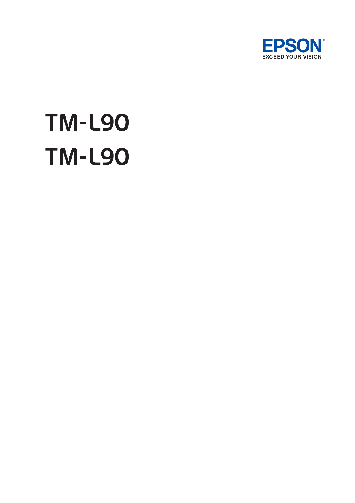
1.2 Name and Description of Each Part
Cutter cover
Control panel
Roll paper cover
Cover open lever
FEED Button
Perforation to pass the
cables through
Manual cutter
Rocker switch (with a
power switch soft cover)
or
Non-locking
push button
Power switch
1.2.1 Part Names (TM-L90)
TM-L90/TM-L90 Peeler Model Technical Reference Guide
* Refer to page 42 for the location of the DIP switches (available only for TM-L90 other than 4** models).
Printer Part Names
Product Overview 13
Page 14
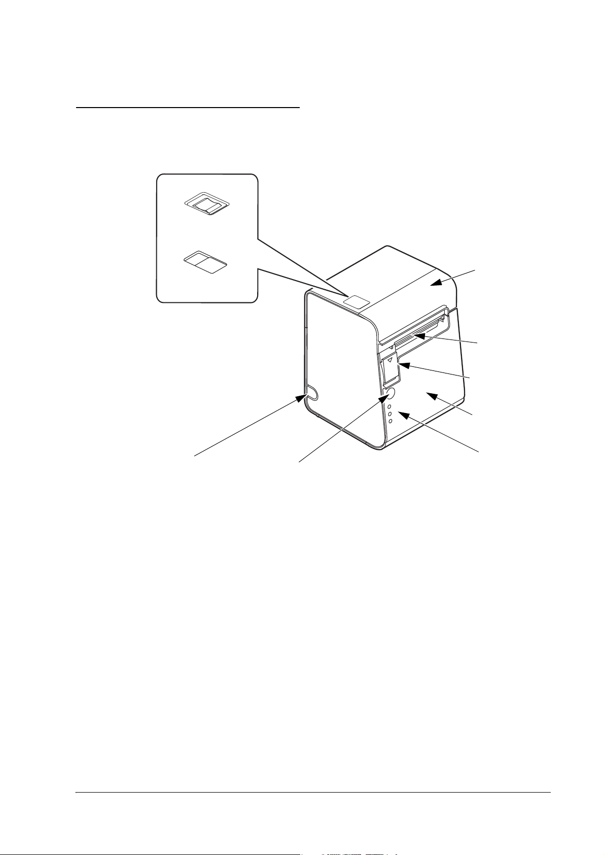
1.2.2 Part Names (TM-L90 Peeler Model)
Cutter cover
Control panel
Roll paper cover
Power switch
Peeler cover
FEED Button
Wiring knockout
Manual cutter
Peeler open lever
Cover open lever
Label peeling sensor
Rocker switch (with a
power switch soft cover)
or
Non-locking
push button
Power switch
* Refer to page 42 for the DIP switch positions. (available only for TM-L90 Peeler other than 39* models)
Part Names of TM-L90 Peeler Model
14 Product Overview
Page 15
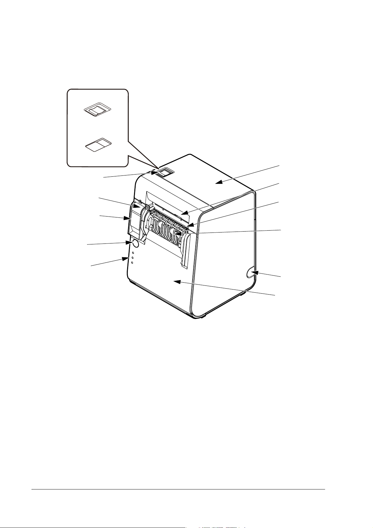
1.2.3 Paper FEED button inside the printer
Paper FEED button
(inside the printer)
ERROR LED
PAPER OUT LED
FEED Button
POWER LED
Another FEED button is located under the roll paper cover.
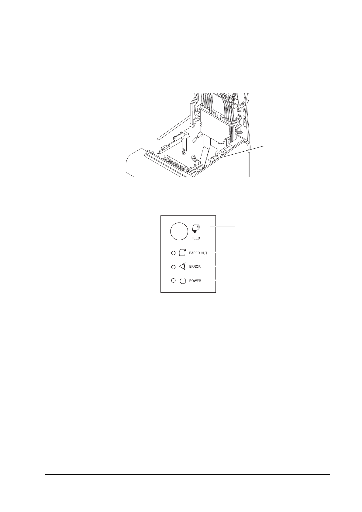
1.2.4 Control Panel
TM-L90/TM-L90 Peeler Model Technical Reference Guide
FEED button (with the TM-L90)
When using label paper or receipt paper with black mark:
❏
Pressing this button feeds paper to the next print starting position.
When using receipt paper:
❏
Pressing this button once feeds paper by one line. Holding this button down feeds paper continuously.
FEED button (with the TM-L90 Peeler Model)
When using label paper or receipt paper with black mark:
❏
Pressing this button feeds paper to the next print starting position.
❏
Pressing this button after opening/closing the roll paper cover initializes the mechanism. (After closing
the roll paper cover, the status changes to waiting to print when FEED button is pressed)
❏
When error recovery with FEED button is enabled by memory switch 8-1, if a paper layout error occurs,
pressing FEED button recovers from the error and performs automatic paper layout.
Product Overview 15
Page 16

When using receipt paper:
❏
Pressing this button once feeds paper by one line. Holding this button down feeds paper continuously.
PAPER OUT LED (with the TM-L90)
❏
Lights when there is no more roll paper or there is little remaining.
(Default setting. The LED condition varies according to the memory switch settings. Refer to "Memory
Switch Settings" on page 42 and "Error Code" on page 111 for details.)
❏
Off when there is a sufficient amount of roll paper remaining.
(Default setting. The LED condition varies according to the memory switch settings. Refer to "Memory
Switch Settings" on page 42 and "Error Code" on page 111 for details.)
❏
Flashes when a self test is in progress or when the printer waits for the macro execution switch to go on.
PAPER OUT LED (with the TM-L90 Peeler Model)
❏
Lights when there is no more roll paper or there is little remaining.
(Default setting. The LED condition varies according to the memory switch settings. Refer to "Memory
Switch Settings" on page 42 and "Error Code" on page 111 for details.)
❏
Off when there is a sufficient amount of roll paper remaining.
(Default setting. The LED condition varies according to the memory switch settings. Refer to "Memory
Switch Settings" on page 42 and "Error Code" on page 111 for details.)
❏
Flashes when a self test is in progress or when the printer waits for the macro execution switch to go on.
❏
When the roll paper is inserted and the roll paper cover is closed, one label is ejected and the LED starts
flashing. It flashes until FEED button is pressed.
❏
When a label is issued, flashing starts after it is issued. The LED flashes until the label is removed from
the peeler.
POWER LED
❏
Lights when the power supply is on.
❏
Off when the power supply is turned off.
❏
Flashes during execution of each operation.
ERROR LED
❏
Lights when the printer is offline.
❏
Off under normal conditions.
❏
Flashes when an error occurs. (Refer to "Error Code" on page 111 for details)
16 Product Overview
Page 17

TM-L90/TM-L90 Peeler Model Technical Reference Guide
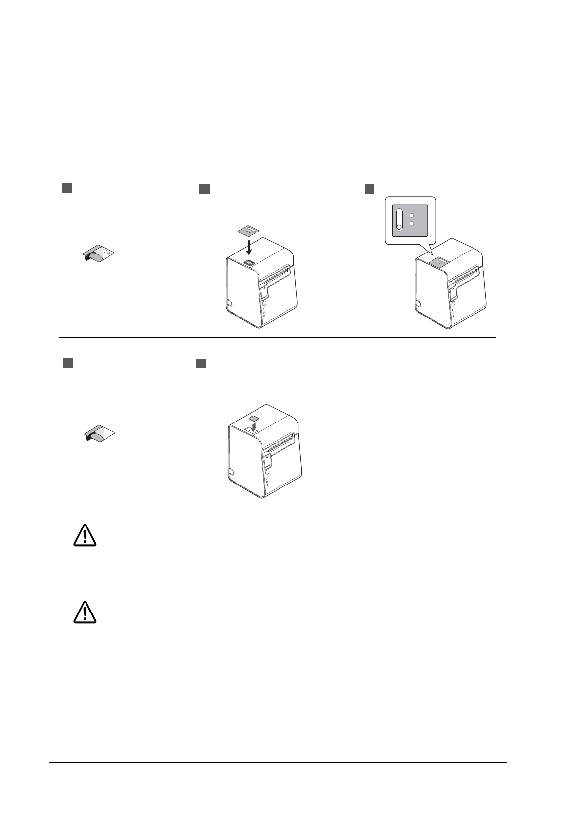
1.2.5 Power Switch
Refer to "Printer Part Names" on page 13 for the power switch location. The type of the power switch
differs, depending on models and functions may differ, depending on the models. Therefore, be sure to
check the type of the power switch of your printer and a model number on the manufacturer’s plate of
your printer.
Rocker switch (TM-L90 4** models, TM-L90 Peeler 39* models):
Turns the printer on or off. The marks on the switch: ( / )
Non-locking push button (TM-L90 other than 4** models, TM-L90 Peeler other than 39* models):
Turn on the power by holding down the POWER button 1 second or longer. Turn off the power by
holding down the POWER button 3 seconds or longer.
The printer is normally turned on/off with this switch. You can select whether to enable or disable the
power switch using the DIP switches.
When the DIP switches are set to OFF (power switch enabled), the power switch controls the TM
printer as follows.
When the TM is turned off:
The TM printer is powered ON when the power switch is pressed more than 1 second.
When the TM is turned on:
The TM printer is powered OFF when the power switch is pressed more than 3 seconds.
If for some reason pressing the power switch even more than 10 seconds does not turn the power
off, the TM printer executes a forced power off.
Note:
When the DIP switches are set to ON (power switch disabled), use direct control of the printer with ESC/POS
commands. (For details, refer to "TM Printer Operation Performed When Power Switch is Disabled" on page
101.)
Note:
Make sure to check whether the AC adapter is connected to the power supply before turning on the power
switch of the printer.
Product Overview 17
Page 18
1.2.6 Power Switch Cover
2
3
1
2
1
TM-L90 4** models, TM-L90 Peeler 39* models
TM-L90 other than 4** models, TM-L90 Peeler other than 39* models
To prevent unintentional contact or improper changes and to improve the appearance, use a power switch
cover. When using the power switch cover, to turn on or off the TM printer, press the power switch
through the hole in the power switch cover. Attach the cover as shown in the illustrations below.
WARNING:
If an accident occurs with the power switch cover attached, unplug the power cord immediately. Continued
use may cause fire or shock.
CAUTION:
Do not remove the power switch soft cover. (only for TM-L90 4** models and TM-L90 Peeler 39* models)
18 Product Overview
Page 19
TM-L90/TM-L90 Peeler Model Technical Reference Guide
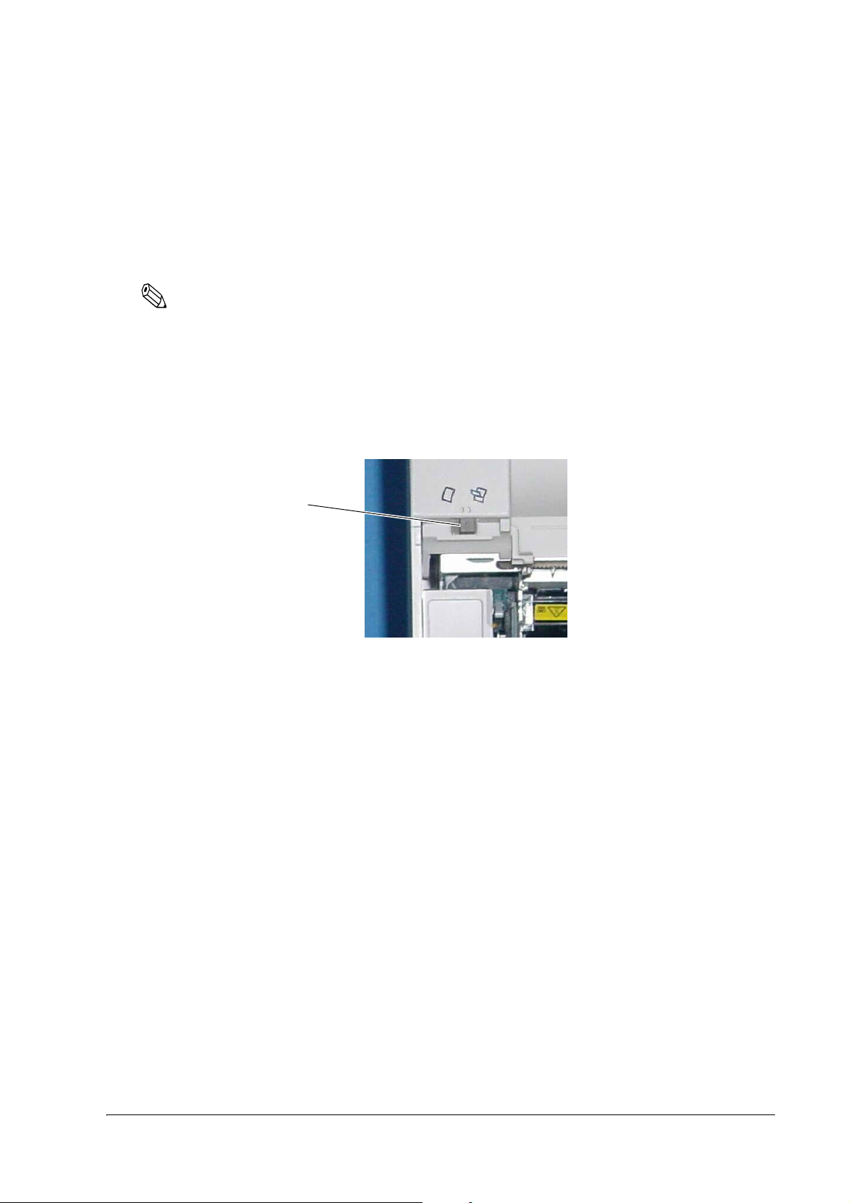
mode switch
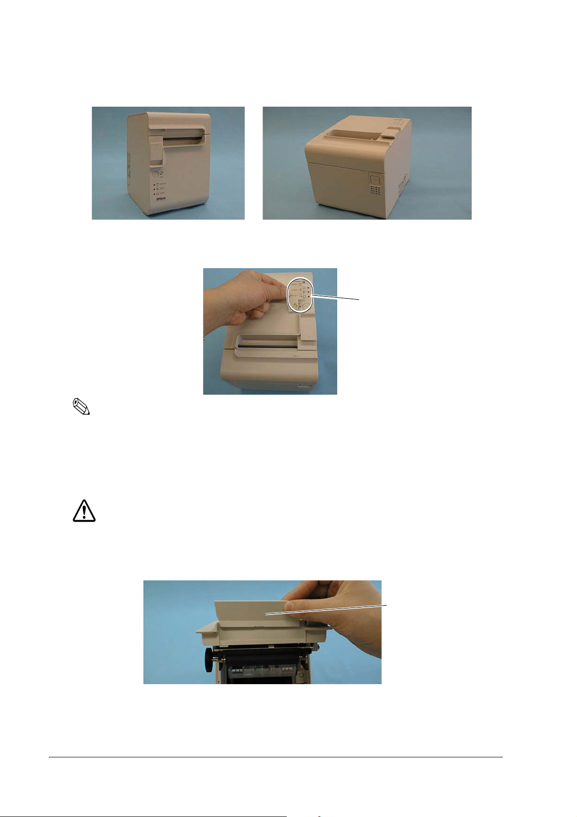
1.2.7 Mode Switch (TM-L90 Peeler Model Only)
With the TM-L90 Peeler Model, you can select the peeling issuing mode and continuous issuing mode
with the mode switch. The mode switch switches between the peeling issuing mode and continuous
issuing mode.
The mode switch is inside the top left of the printer when the roll paper cover is opened.
Note:
Be sure that the peeler cover and the roll paper cover are open when switching the modes. The setting is
effective when the power is turned on or the covers are closed. If the mode is switched with the covers
closed, the setting will not be changed.
Be sure not to use a ball point pen to switch the modes. A ball point pen can damage the switch.
To use the peeling issuing mode, move the mode switch to the right.
To use the continuous issuing mode, move the mode switch to the left.
Product Overview 19
Page 20
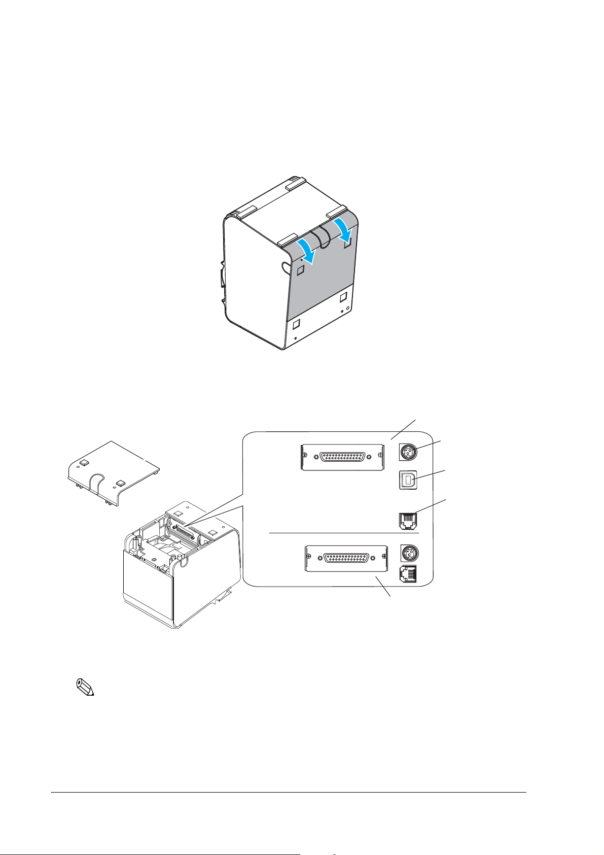
1.2.8 Connectors
Drawer kick
connector
power supply
connector
TM-L90 4** models,
TM-L90 Peeler 39* models
TM-L90 other than 4** models,
TM-L90 Peeler other than 39* models
USB interface
Remove the bottom of the cover as shown in the illustration below. All cables are connected to the
connector panel located on the lower rear side of the printer.
The connector panel differs, depending on the models.
Connector Panel
Note:
The model pictured is a serial interface model. For other information on interfaces and connectors, refer to
"Connecting the Cable" on page 63.
20 Product Overview
Page 21

TM-L90/TM-L90 Peeler Model Technical Reference Guide
Chapter 2
Setup
2.1 Setup Flow
Before using the printer, you need to set various settings to increase the printer's functionality. Configure
the printer appropriately depending on the environment.
Determine how to install the printer (install it vertically or horizontally)
Set the Roll Paper Near-End Detector
Connect the AC adapter
Autocutter settings (TM-L90 only)
Set the Roll Paper width
DIP switch settings
Memory switch settings
Set the Paper layout
Setup 21
Page 22

2.2 Installation Procedures
2.2.1 Precaution For Installation
❏ TM-L90
• Locate the printer on a flat surface, whichever orientation you choose.
• Avoid locations susceptible to dust and other foreign matter.
• Avoid resting the printer on the power supply or other cables or other objects.
• Consider vibration during paper cutting and drawer usage. Take measures to prevent the printer
from moving.
❏ TM-L90 Peeler Model
• Locate the printer on a flat surface.
• Avoid locations susceptible to dust and other foreign matter.
• Avoid resting the printer on the power supply or other cables or other objects.
• Consider vibration during paper cutting and drawer usage. Take measures to prevent the printer
from moving.
• To prevent malfunction of the label peeling sensor, do not locate the printer in direct sunlight.
22 Setup
Page 23
TM-L90/TM-L90 Peeler Model Technical Reference Guide
2.2.2 Instructions for Installation
The TM-L90 can be placed vertically (paper outlet in front), horizontally (paper outlet at the top), or
attached to a wall (using the optional wall hanging set WH-10).
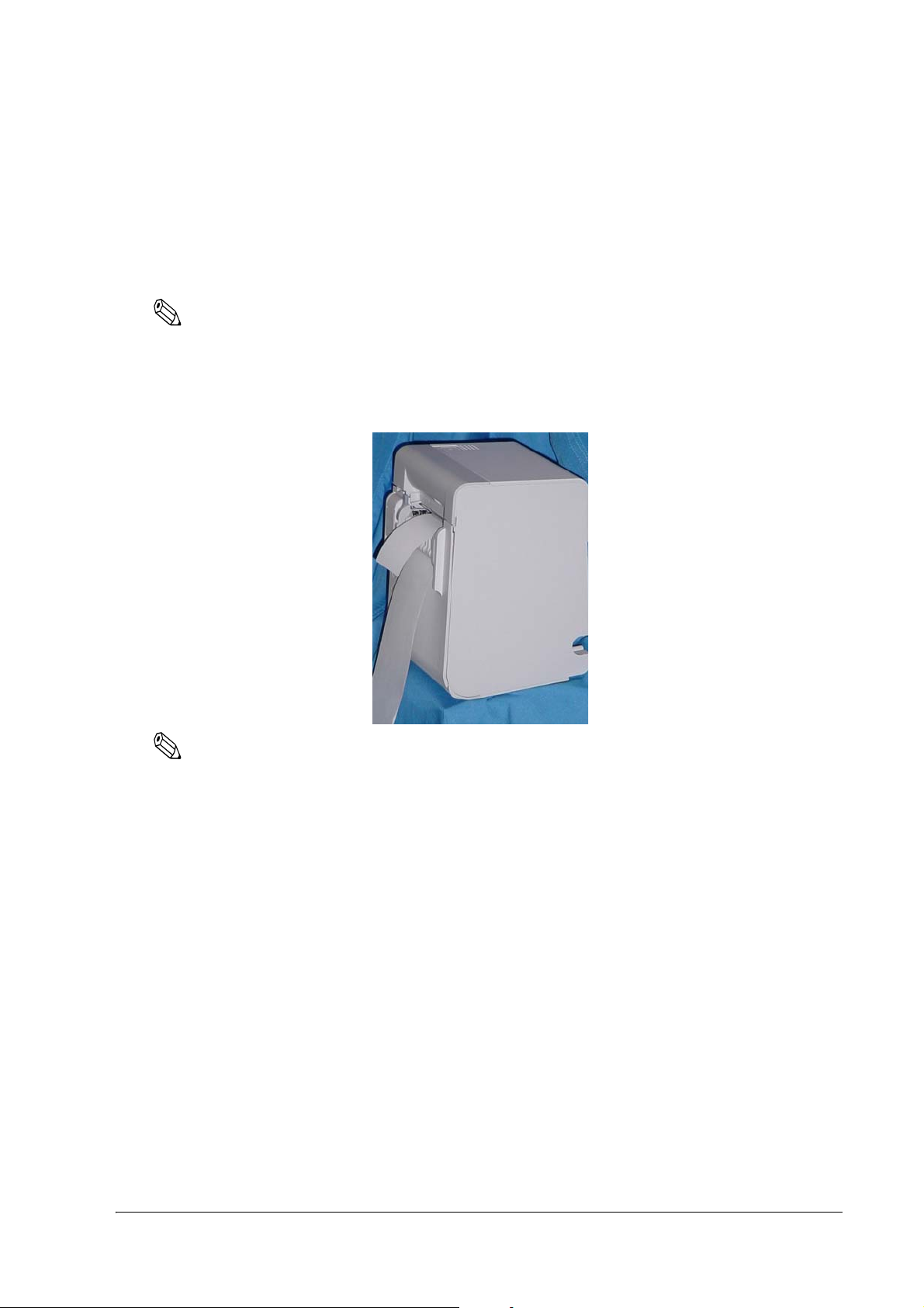
With the TM-L90 Peeler Model, you can use it vertically or wall mounted with either peeling issuing or
with continuous issuing (not using the peeler).
Note:
For the TM-L90 Peeler Model, horizontal installation is prohibited to avoid jams caused by re-sticking of
backing paper and a label.
The illustration below shows the vertical installation for the TM-L90 Peeler Model.
Note:
To hang the printer on the wall, see the Wall Hanging Bracket Set Installation Manual provided with the
WH-10 for instructions.
It is recommended to take some measures so that the printer will be stable when paper is being loaded or a
drawer is being used. The DF-10 (affixing tapes) for fixing the printer is provided as an option.
When using the printer with the peeling issuing mode, be sure to install the printer so that a peeled label will
not contact the used backing paper. Re-sticking of a peeled label to the backing paper will cause jams.
For the TM-L90, when changing the way of installation, you need to adjust the following items:
• Control panel label used for horizontal installation
• The location of the Roll Paper Near-End Detector
The following figure shows the TM-L90 placed both vertically and horizontally.
Setup 23
Page 24
When you install the printer horizontally, attach the control panel label as shown in the illustration below.
Control panel label
paper exit guide
Note:
To hang the printer on the wall, see the Wall Hanging Bracket Set Installation Manual provided with the
WH-10 for instructions.
When you use TM-L90 horizontally, peel off the backing sheet of the paper exit guide and attach it as
shown below to prevent cut paper from falling inside the printer after paper is cut by the autocutter.
CAUTION:
When using the paper exit guide, do not use roll paper with a core that is smaller than the specification
(inside diameter: 25.4 mm, outside diameter: 31.4 mm). Using a smaller one may cause a paper jam at the
attached paper exit guide.
24 Setup
Page 25
TM-L90/TM-L90 Peeler Model Technical Reference Guide
Detector adjustment screw
N.E. detector holder
N.E. detector
(location when installing
horizontally)
N.E. detector window
when installing vertically
2.3 Adjusting Roll Paper Near-End Detection Position
2.3.1 With TM-L90
Below are three situations when roll paper N.E. detector adjustment is required.
❏ When changing the way of installation. (Vertically ↔ Horizontally)
❏ To adjust the location of detection to suit the diameter of the roll paper core used.
❏ To adjust the amount of remaining paper desired.
Note:
Roll paper centers are manufactured according to various specifications, making it impossible to exactly
detect the remaining amount of paper.
1. Open the roll paper cover.
2. Remove the roll paper.
Part names and the locations of N.E. detector components
Setup 25
Page 26
3. Loosen the detector adjustment screw using a coin or similar tool.
Detector
adjustment
screw
Move the N.E. detector
holder in the direction of
the arrow to make the
detector come out from the
window for either vertical
or horizontal installation.
4. The adjustment position of the roll paper Near-End detector changes depending on the way of
installation. In either case (vertical or horizontal), adjust the detector so that its tab comes out from
the hole near the bottom of the printer. (Refer to "Adjusting Roll Paper Near-End Detection Position"
on page 25, "Adjustment Positions of N.E. Detector" on page 27.
Note:
When changing the position of the N.E. detector in accordance with the change of installation, move the roll
paper N.E. detector as the above arrow shows while holding down the detector.
26 Setup
Page 27
TM-L90/TM-L90 Peeler Model Technical Reference Guide
N.E. detector holder
Adjustment direction for
horizontal installation
Adjustment direction for vertical
installation
Holder Position #1 for horizontal Holder Position #2 for horizontal
Holder Position #1 for vertical Holder Position #2 for vertical
5. To fine tune the amount of remaining paper that is detected by the N.E. detector, move the N.E.
detector holder shown in the illustration "N.E. Detector Holder" on page 27 and adjust the position.
Note:
Note that the direction to move the roll paper N.E. detector varies depending on the method of printer
installation (vertical/horizontal).
N.E. Detector Holder
Adjustment Position Number Specified Thermal Paper Dimension
#1 Approximately 36 mm {1.42"}
#2 Approximately 41 mm {1.61"}
Adjustment Positions of N.E. Detector
Setup 27
Page 28
6. Tighten the detector adjustment screw using a coin or similar tool.
Check that the N.E. detect lever is
operating properly.
7. Move the N.E. detect lever by hand (finger) to confirm that it moves smoothly.
8. Load the roll paper.
9. Close the roll paper cover.
28 Setup
Page 29
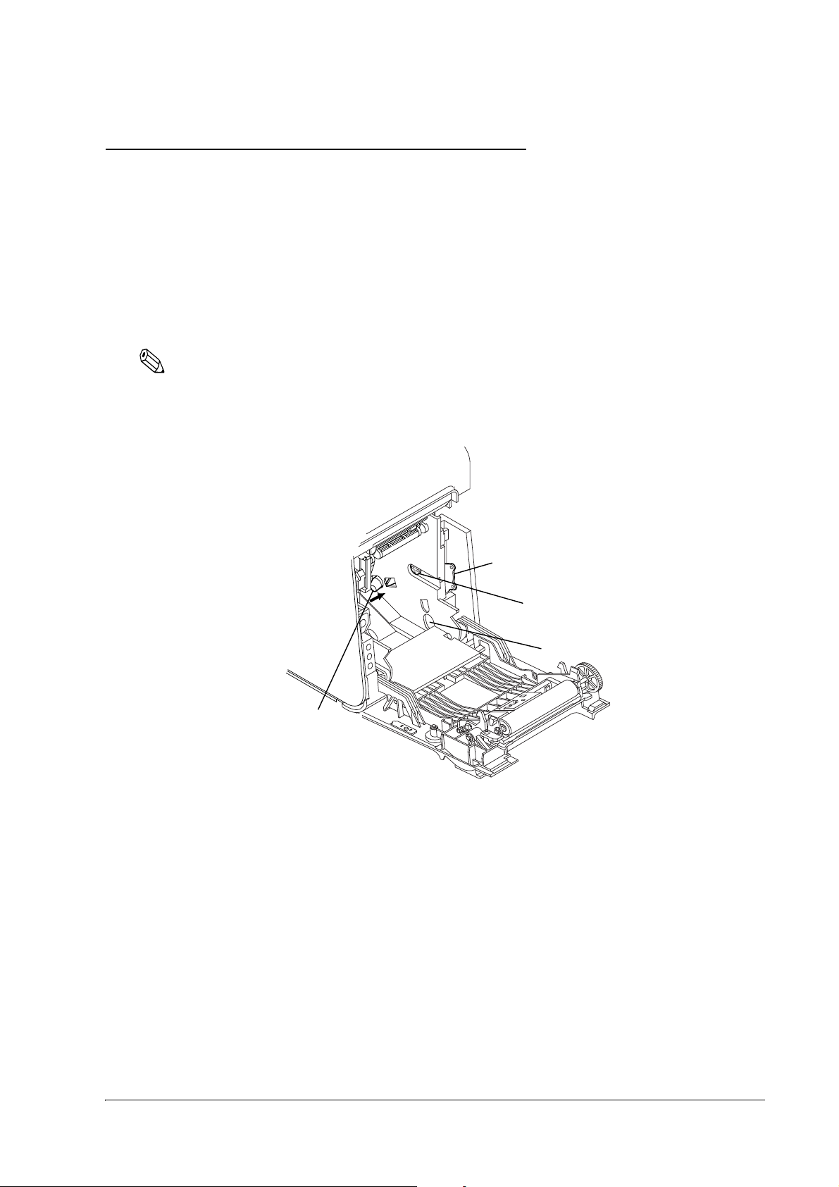
TM-L90/TM-L90 Peeler Model Technical Reference Guide
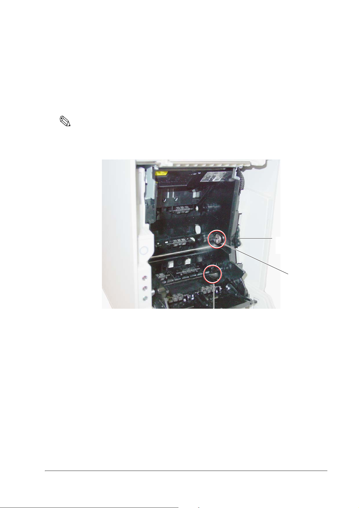
sensor adjustment
screw
near end sensor holder
near end sensor window (the photo shows the
sensor projecting from the window)
2.3.2 With the TM-L90 Peeler Model
In the following 2 cases, it is necessary to adjust the position of the roll paper near end sensor.
❏ When adjusting the detection position according to the thickness of the roll paper core
❏ When adjusting the amount remaining paper desired
Note:
Since the shape of the central part of the roll paper may differ slightly according to the specification, it is not
possible to detect near end exactly.
Part names and the locations of N.E. detector components
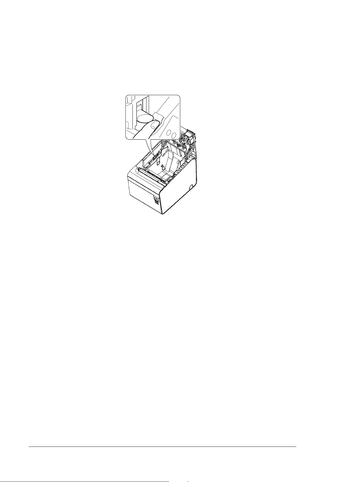
1. Open the peeler cover.
2. Open the roll paper cover.
3. Take out the roll paper.
Setup 29
Page 30
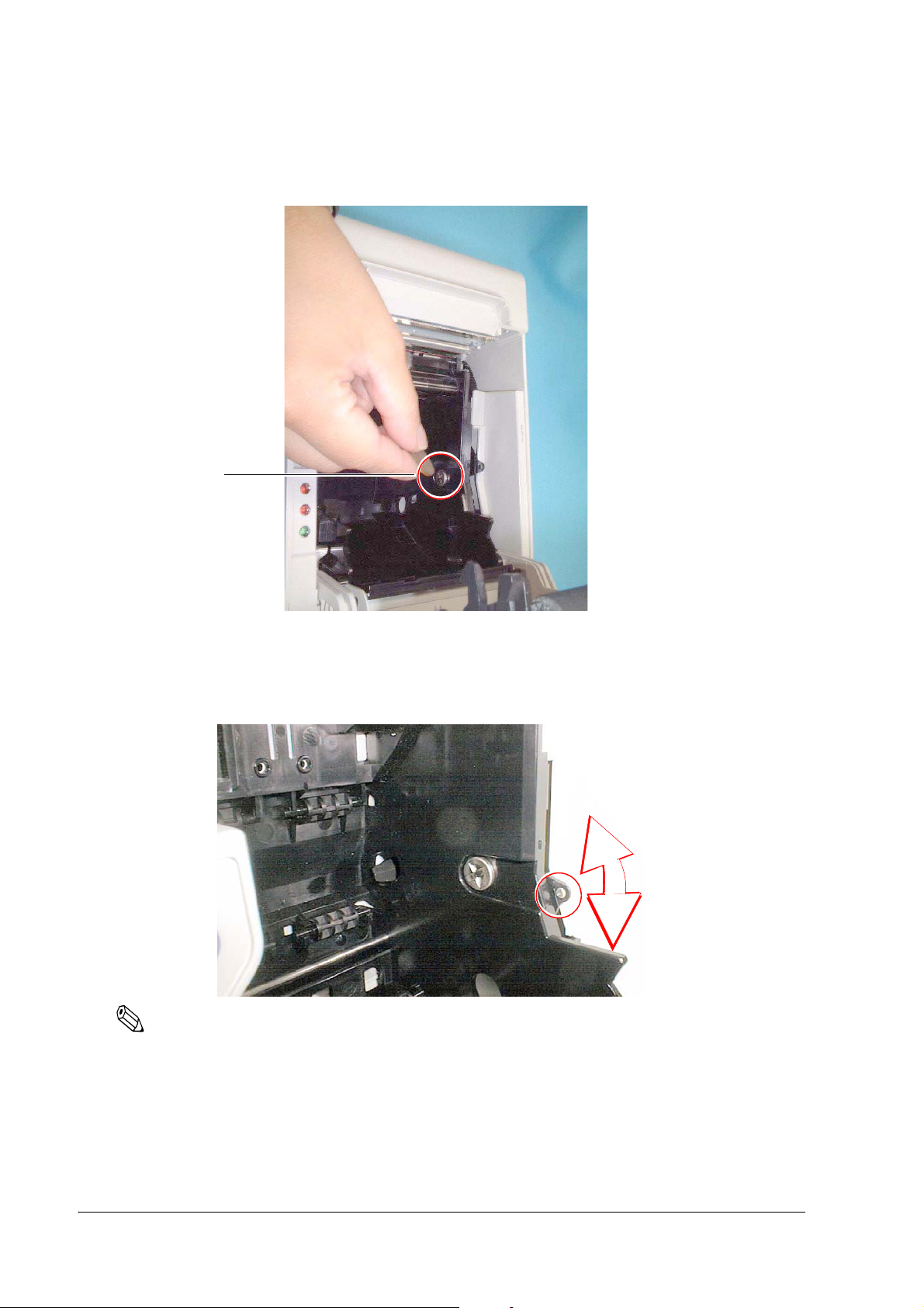
4. Using a coin or similar tool, loosen the sensor adjustment screw.
sensor
adjustment
screw
Adjust the sensor so that it projects
from the window.
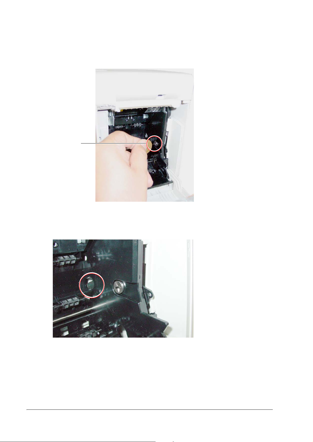
5. Adjust the roll paper near end sensor so that the claw of the roll paper near end sensor projects from
the hole near the bottom of the device. (Refer to "Part names and the locations of N.E. detector
components" on page 25 and "Near end sensor adjustment position" on page 31.)
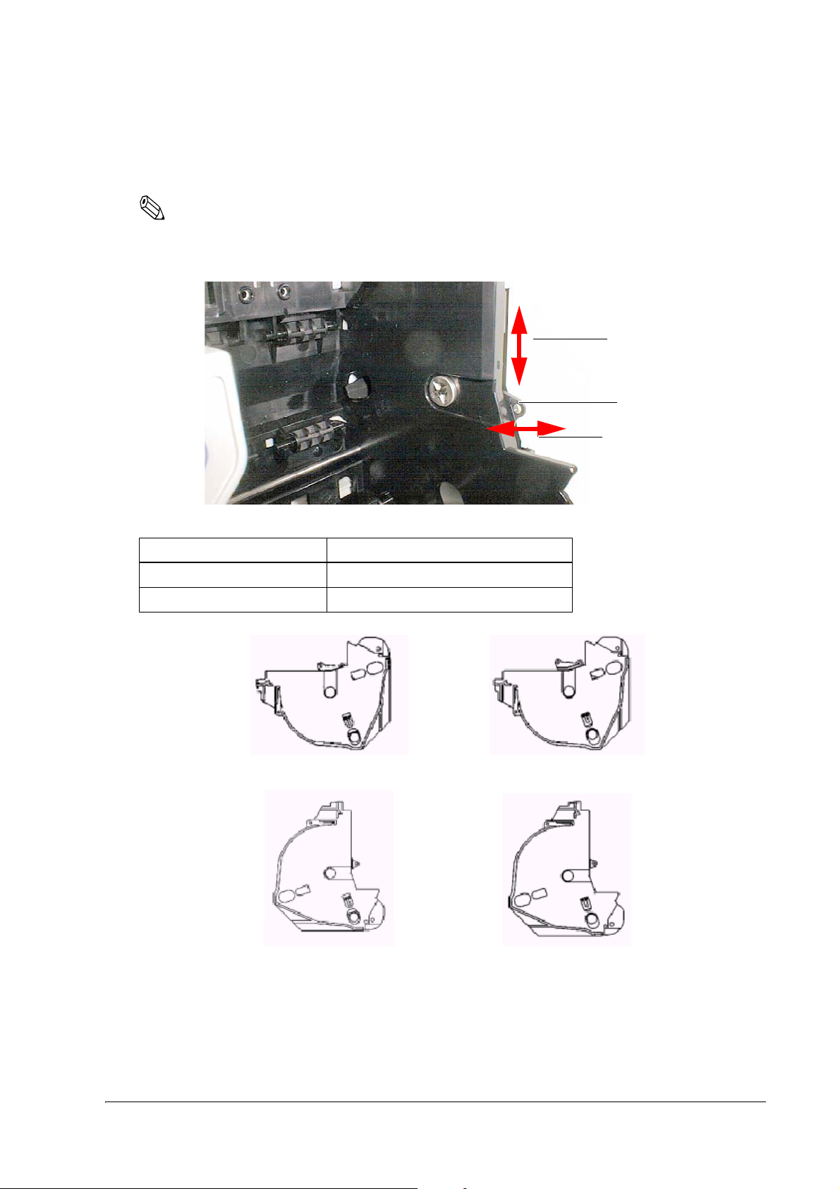
6. To make fine adjustments to the amount of paper remaining detected by the roll paper near end
sensor, finely adjust the position of the near end sensor holder by moving it in the direction of the
arrows as shown in the figure "N.E. Detector Holder" on page 27.
30 Setup
Page 31

TM-L90/TM-L90 Peeler Model Technical Reference Guide
N.E. detector holder
Adjustment direction
when the sensor holder position is #1
when placed vertically
when the sensor holder position is #2 when
placed vertically
Note:
Move the N.E. detector in the direction shown by arrow.
Near end sensor holder
Adjustment scale Outside diameter of specified thermal paper
#1 Approximately 36 mm {1.42"}
#2 Approximately 41 mm {1.61"}
Note:
Adjust the sensor while checking the position of the parts circled in the following figure.
Near end sensor adjustment position
Setup 31
Page 32

7. Using a coin or similar tool, tighten the sensor adjustment screw.
push the near end sensor with your
finger and check that it moves
smoothly
8. Push the near end sensor with your finger and check that it moves smoothly.
9. Set the roll paper.
10. Close the roll paper cover.
32 Setup
Page 33

TM-L90/TM-L90 Peeler Model Technical Reference Guide
2.4 Connecting AC adapter (PS-180)
Be sure to use the PS-180 or the equivalent product as the AC adapter.
CAUTION:
Be sure to remove the AC cable from the wall outlet whenever connecting or disconnecting the AC adapter
to the printer. Failure to do so may result in damage to the AC adapter or the printer.
Be sure to confirm that the wall outlet power supply satisfies the rated voltage requirements of the AC
adapter. Never insert the AC cable plug into a socket that does not meet the rated voltage requirements of
the AC adapter. Doing so may result in damage to both the AC adapter and the printer.
2.4.1 Attaching AC adapter
The following is an explanation of the procedure for attaching the power unit to the TM-L90.
1. Confirm that the printer's power supply is turned off and the AC adapter's AC cable has been removed
from the wall outlet.
2. To place cables, first break off by hand any of the three perforations to pass the cables through
indicated by circles in the illustration (the other one is on the right). Then put the cables through the
holes and replace the bottom of the cover.
Setup 33
Page 34

3. Remove the bottom of the cover as shown in the illustration below.
Power supply connector
4. Install the connector of the DC cable onto the DC connector (labeled DC24V).
Power Supply Connector
Note:
The connector panel varies depending on the models.
When removing the DC cable connector from the printer, first confirm that the AC cable has been
disconnected from the wall outlet; then grasp the arrow marked section of the connector and pull straight out.
2.4.2 Caution about AC adapter and Supply Voltage
❏ ERROR LED flashes when a high voltage or low voltage error occurs. In such cases, immediately turn
the power off.
Refer to "Unrecoverable errors" on page 114 for the LED flashing patterns.
34 Setup
Page 35

TM-L90/TM-L90 Peeler Model Technical Reference Guide
2.5 Autocutter Settings (TM-L90 only)
The TM-L90 has an autocutter attached for cutting the paper. The autocutter can perform 2 cuts, "partial
cut," in which a small part is left uncut on the left edge, and "full cut" (default setting), in which the paper is
cut completely. By adjusting the attachment position of the cutter unit, you can select between "partial cut"
and "full cut."
Note:
You can't configure the autocutter setting (Partial cut/Full cut) through a software command.
You can't change from partial cut setting to full cut setting after using the printer with partial cut setting.
Since the partial cut doesn't use the tip of the blade, it might have deteriorated. Contact the nearest Epson
service center if you'd like to do the above change.
To disable the autocutter, change the memory switch (MSW2-2) settings. (Refer to "Memory Switch Settings"
on page 42).
Performing full cut without the paper exit guide when the printer installed horizontally may cause a doublecut, paper jam or autocutter error because a cut sheet may drop in the paper path. Be sure to attach the paper
exit guide when performing a full cut in the horizontal installation. (Refer to "Instructions for Installation"
on page 23 for instructions on attaching the guide.)
2.5.1 Cautions on the Lengths of the Receipts/Labels to Issue
• To prevent the cut receipts or labels from getting stuck in the paper path, causing paper jams.
• To make the cut receipts or labels easy to remove
The lengths of the receipts and labels to issue is recommended as shown in the table below.
Use condition Recommended issuing length
Horizontal installation (full cut)*
Horizontal installation (partial cut)*
Vertical installation
Note 1: Install the paper exit guide packed in the box with the printer when the autocutter is used with a full cut, with the printer
positioned horizontally.
2: Partial cut (one point left uncut) is available only when using receipt paper or continuous label paper without black marks.
Also, do not perform cutting and reverse feed together.
1
2
Note:
If the lengths of receipts or labels are specified shorter than the recommended lengths, the issued receipts or
labels may be hard to remove. Users must make a thorough evaluation of the lengths to specify before using
the printer.
37.5 mm or more
25.4 mm or more
Setup 35
Page 36

2.5.2 Setting Procedure
cutter cover
Remove this screw
Cutter unit
Loosen this screw
Lift upwards
1. Turn off the power.
2. Pull the cover open lever, and open the roll paper cover.
3. Push the body case outward (in the direction of the 2 arrows) and remove the cutter cover.
4. Remove the single screw retaining the cutter unit and loosen the screw indicated by the circle in the
illustration below.
36 Setup
5. Lift the top of the cutter unit upward and remove it.
Page 37

TM-L90/TM-L90 Peeler Model Technical Reference Guide
Shift to dowel of
desired cut method
Partial cut Full cut
dowels
6. Moving the cutter unit in a lateral direction, shift to the dowel position of the desired cut method.
7. Secure the cutter unit again using the removed screw and the loosened screw.
8. Install the cutter cover.
9. Close the roll paper cover.
Setup 37
Page 38

2.6 Setting Roll Paper Width
tabs
front edge
shaft
notch
protrusion
The TM-L90 / TM-L90 Peeler Model uses a roll paper 80 mm wide in the default state. When using a roll
paper 38 to 70 mm wide with this printer, attach the roll paper spacer in accordance with the following
procedure.
Note:
If a printer has already been used, the paper width cannot be changed from narrow to wide. This is because
the part of the head that made direct contact with the platen may have been damaged when narrow roll
paper was used. The paperless part of the cutter blade may also have worn.
Only when the printer is not yet used can the paper width be changed from narrow to wide.
The following explains the procedure for setting the roll paper width for the TM-L90.
1. When using 61 mm to 70 mm roll paper, break off the two tabs of the roll paper spacer.
Note:
You can still use widths from 38 mm to 60 mm after breaking the tabs off.
38 Setup
2. Open the roll paper cover.
3. As shown below, insert the roll paper spacer so that the front edge goes through the notch in the
printer, and fit the protrusion of the roll paper spacer on the shaft.
Page 39

TM-L90/TM-L90 Peeler Model Technical Reference Guide
screw
measurement
4. Push the roll paper spacer until it clicks.
Note:
Check that the roll paper spacer slides smoothly from side to side.
5. Slide the roll paper spacer side-to-side and set it to the appropriate position. Use the measurement
lines if necessary.
Note:
Roll paper is placed on the tab-free side of the roll paper spacer.
When positioning the roll paper spacer, provide 0.5 mm of room for the maximum roll paper width.
6. Secure the roll paper spacer with the supplied screw. (See above.)
7. Make the setting for the paper width with the memory switch.
For information about the memory switch, see "Memory Switch Settings" on page 42.
Setup 39
Page 40

2.7 DIP Switch Settings
DIP switch cover
DIP switches
The following models have the DIP switches for settings.
❏ TM-L90 other than 4** models
❏ TM-L90 Peeler other than 39* models
The DIP switches are located inside the printer as shown the picture below.
Before setting DIP switches, remove the DIP switch cover.
Note:
Set the DIP switches after turning off the printer. The settings will not be enabled if they are set with the
power on.
40 Setup
Page 41

TM-L90/TM-L90 Peeler Model Technical Reference Guide
DIP switch settings (Serial interface model)
SW No. Function ON OFF Initial Setting
1 Enable/disable Power
switch.
2 Select for serial
communication condition.
3 Handshake XON/XOFF DTR/DSR OFF
4 Bit length 7 bits 8 bits OFF
5 Parity check Yes No OFF
6 Parity type Even Odd OFF
7 Baud rate (bps) 7 8
8 OFF
bps: Indicates the number of bits transferred per second.
DIP switches 2 to 8 are for serial communication. Not used in parallel communication.
Switches power supply On/
Off using commands. (Power
switch is disabled.)
Set using DIP switch 1-7, 1-8 Set using memory switches. ON
ON ON :2400
OFF ON :4800
ON OFF :9600
OFF OFF :19200
Power switch is used to
switch power On/Off.
OFF
OFF
Note:
When you set the baud rate with the memory switch, you can set faster communication than with the DIP
switch. (Refer to "Memory Switch Settings" on page 42, "Error Code" on page 111)
In serial communication, intermittent printing* may occur. This is because when the communication speed
is low, a data transmission waiting state occurs frequently since the printing mechanism speed is high.
Increasing the communication speed may reduce this symptom.
* Intermittent printing: White streaks as large as one or two hairs appear horizontally in a printing result.
DIP switch settings (Parallel, USB, Ethernet model)
SW No. Function ON OFF Initial Setting
1 Enable/disable Power
switch.
2 Reserved Fixed to on -- ON
3 Reserved -- Fixed to off OFF
4 Reserved -- Fixed to off OFF
5 Reserved -- Fixed to off OFF
6 Reserved -- Fixed to off OFF
7 Reserved -- Fixed to off OFF
8 Reserved -- Fixed to off OFF
bps: Indicates the number of bits transferred per second.
DIP switches 2 to 8 are for serial communication. Not used in parallel communication.
Switches power supply On/
Off using commands. (Power
switch is disabled.)
Power switch is used to
switch power On/Off.
OFF
Setup 41
Page 42

2.8 Memory Switch Settings
The printer has the following software switches, called memory switches, in the non-volatile memory.
❏ Msw1, Msw2, Msw5, Msw7, Msw8
❏ Customized values
❏ Serial communication conditions
❏ USB communication conditions
Note:
Msw5, Msw7, and USB communication conditions are available only for TM-L90 4** models or TML90 Peeler 39* models.
These settings can be made by the Memory Switch Setting Utility (see page 89), the Memory Switch Setting
Mode (see page 42), or ESC/POS commands.
For details of ESC/POS commands, refer to the “ESC/POS Command Reference”. For details on how to
obtain this manual, see "Introduction of Control Methods" on page 83.
For usage of the Memory Switch Setting Utility, refer to the user's manual of the utility.
For usage of the Memory Switch Setting Mode, see "Memory switches of TM-L90" on page 43 for TM-L90
4** models, TM-L90 Peeler 39* models, or "Memory switches of TM-L90 Peeler Model" on page 48 for
TM-L90 other than 4** models, TM-L90 Peeler other than 39* models.
42 Setup
Page 43

TM-L90/TM-L90 Peeler Model Technical Reference Guide
2.8.1 Memory switches of TM-L90
In the following tables, “✓” shows that the setting can be set by the utility or the setting mode.
Msw1
Initial
Msw Function Off On
1-1 Transmission of Power-on
notice
1-2 Receive buffer capacity 4K bytes 45 bytes Off ✓✓
1-3 BUSY condition Receive buffer
1-4 Data processing for receive
error
1-5 Automatic line feed Disabled Enabled Off ✓✓
1-6 (Reserved) Fixed to Off Off
1-7 #6 pin of RS-232 Not used Used for reset Off ✓✓
1-8 #25 pin of RS-232 Not used Used for reset Off ✓✓
[Msw1-4], [Msw1-7], [Msw1-8]: Valid only for serial interface
[Msw1-5]: Valid only for parallel interface
[Msw1-7], [Msw1-8]: Not available for TM-L90 4** models
Disabled Enabled Off ✓✓
Receive buffer
full or Offline
Replaced with
"?"
full
Ignored Off ✓✓
setting
Off ✓✓
Msw Setting
utility
Msw2
Msw Setting
Mode
Initial
Msw Function Off On
2-1 (Reserved) Fixed to On (Do not change) On
2-2 Autocutter function Disabled Enabled On ✓✓
2-3
(Reserved) - - Off
to
2-8
setting
Msw Setting
utility
Msw Setting
Mode
Setup 43
Page 44

Msw5 (only for 4** models)
Msw Function Off On
Initial
setting
Msw Setting
utility
5-1 USB power-saving function Enabled Disabled Off ✓✓
5-2 Recovery conditions from
256 bytes free 138 bytes free Off ✓✓
receive buffer BUSY
5-3 Paper sensor to output paper
end signals
Enabled both
Roll paper end
Disabled Off ✓
sensor and
Roll paper
near-end
sensor
5-4 Error signal output Enabled Disabled Off ✓✓
5-5
(Reserved) - - Off
to
5-8
[Msw5-1]: Valid only when the USB interface communication condition of the built-in USB is set to the Vendor-defined class and the
[Msw5-2]: Valid only when the receive buffer capacity is 4K bytes.
[Msw5-4]: Valid only for parallel interface
system configuration is set so that the USB driver can support the USB power-saving function.
Msw7 (only for 4** models)
Msw Setting
Mode
Msw Function Off On
7-1 Printer operation when print
position misalignment is
detected
7-2 Printer operation in recovery
from paper layout error
Print starting
position is not
changed
Automatic
paper layout
measurement
Print starting
position is
adjusted (*1)
Paper feed to
the next print
starting
Initial
setting
Off ✓✓
Off ✓✓
Msw Setting
utility
Msw Setting
Mode
position (*2)
7-3 Autocut after closing cover Disabled Enabled (*3) Off ✓✓
7-4 Paper feed length after closing
20 mm 40 mm Off ✓✓
cover
7-5
(Reserved) - - Off
to
7-8
(*1) When using label paper or paper with black mark, if print position misalignment is detected during reverse feeding, the printer
feeds the paper to the next print starting position.
(*2) When [Msw8-2] is OFF and the printer recovers from a paper layout error, the printer feeds the paper to the next print starting
position.
(*3) When using paper without black mark (excluding label roll paper), when the roll paper cover is closed, the printer feeds the paper
for the amount set with [Msw7-4], and cuts the paper. After the power is turned on, if printing is executed for the first time after a
cut command is executed, the printer starts printing after executing reverse feeding to the print starting position.
44 Setup
Page 45

Msw8
TM-L90/TM-L90 Peeler Model Technical Reference Guide
Initial
Msw Function Off On
8-1 (Reserved) - - Off
8-2 User operation for recovery
from paper layout error
8-3 Paper out LED state in a paper
near-end
8-4 Maximum length of automatic
paper measurement
8-5 Space insertion at left and right
side of barcode print
8-6 Paper feed to the print starting
position when power is turned
on
8-7 (Reserved) - - Off
8-8 Printer cover open during
operation
Send the error
recovery
command or
open/close
the cover
LED On LED Off Off ✓✓
160 mm 300 mm Off ✓✓
Disabled Enabled Off ✓
Enabled Disabled Off ✓✓
Automatic
recoverable
error
Send the error
recovery
command
Recoverable
error
setting
Off ✓✓
Off ✓✓
Msw Setting
utility
Msw Setting
Mode
When [Msw 8-2] is Off, the paper layout is automatically measured and saved into the non-volatile
memory of the printer after recovery from the error.
If [Msw8-2] is On, the printer paper layout is not changed after error recovery. If the correct paper is not
inserted, the paper layout error will occur again.
The [Msw 8-4] setting influences initialization at power-on when “label paper” or “receipt paper with
black mark” is specified for the paper layout. Refer to "Setting Paper Layout" on page 57 for the paper
layout.
When [Msw 8-6] is set to "Feeding paper to the print starting position at power on is disabled", the printer
does not execute the operation of feeding paper to the print starting position at power on (the printer
executes the operation when its cover is opened and closed). Hence, the user should note the following
points since the printer operates on the assumption that the paper has already been fed to the print starting
position at power on.
a) Turn off the power supply after feeding of paper to the print starting position.
b) Do not open the cover while power is off.
c) If you have opened the cover while the power is off, open and close the cover once while the power is
on to feed the paper to the print starting position.
If printing is performed without the operation described above, the paper layout error (recoverable
error) may occur. If the error occurs, recover from the error by the operation selected with [Msw8-2].
If the print starting position has not been set at power-on, the printing position of the first sheet may shift,
or a paper layout error may occur.
Setup 45
Page 46

Customized values
Option
Item
NV user memory capacity 1KB
(underlined: initial setting)
, 64KB, 128KB, 192KB ✓
NV graphics memory capacity None, 64KB, 128KB, 192KB, 256KB, 320KB,
384KB
Print density 70%, 75%, 80%, 85%, 90%, 95%, 100%, 105%,
, 115%, 120%, 125%, 130%, 135%, 140%
110%
Print speed Level 1 (Slow) - Level 6
Default character code table
*1
Initial setting: Page 0: PC437 (USA, Standard
- Level 9 (Fast) ✓✓
Europe)
Default international character
Selection of the interface
*1
*1
Number of divisions of thermal head
Initial setting: USA ✓✓
Auto, UIB, Built-in USB ✓✓
, 2, 3, 4 ✓
1
energizing
*1
Automatic replacement of Font A
Automatic replacement of Font B
Paper selection
(monochrome or two-color)
Paper width 38 mm - 80 mm
Do not replace, Font B ✓✓
*1
*2
Do not replace, Font A ✓✓
Monochrome, two-color ✓✓
(1 mm pitches) ✓✓
Msw
Setting
utility
Msw
Setting
Mode
✓
✓✓
*1
✓✓
*3
Black-color density in two-color
printing
Buzzer control
*2
*1
Light, Medium, Dark ✓
Buzzer selection: Internal, Option, Disable
✓✓
Buzzer frequency: Continuous, 1 time, No
sound
Sound pattern: Pattern A, B, C, D, or E
(Refer to "Setting items of TM-L90 4** models"
on page 119, about the initial settings.)
*1: Not available for TM-L90 other than 4** models
*2: Not available for TM-L90 4** models
*3: Selectable 38, 58, 60, 70, 80 mm only
Note:
❏
The maximum print speed is available for only the one-part energizing mode. However, if the print duty
is too high in the one-part energizing mode, the printer will automatically reduce the printing speed.
❏
The four-part energizing mode reduces power consumption.
❏
The print width can be set in 43 ways with 1 mm pitches in the range from 38 mm to 80 mm. However, it
cannot be set in the range from 71 mm to 79 mm.
46 Setup
Page 47

❏
Depending on the paper type, it is recommended to set the print density as shown in the table below for
the best print quality.
Paper type Density level
Receipt P35024 90%
KF50 95%
F5041(55) 100%
Label 150PSMW 120%
DTM9502, KL80GT 130%
Serial communication conditions
TM-L90/TM-L90 Peeler Model Technical Reference Guide
Option
Item
Baud rate 2400, 4800, 9600, 19200
Parity None
Flow control DTR/DSR, XON/XOFF ✓✓
Data length 7-bits, 8-bit
(underlined: initial setting)
, 38400, 57600,
115200 bps
, Odd, Even ✓✓
s ✓✓
Msw Setting
utility
✓✓
Note:
For models other than 4** models, these settings are valid only when the DIP switch 1-2 is Off.
USB communication conditions (only for 4** models)
This setting is valid for the built-in USB.
Option
Item
Class Vendor-defined class
(underlined: initial setting)
, Printer class ✓✓
Msw Setting
utility
Msw Setting
Mode
Msw Setting
Mode
Setup 47
Page 48

2.8.2 Memory switches of TM-L90 Peeler Model
In the following tables, “✓” shows that the setting can be set by the utility or the setting mode.
Msw1
Initial
Msw Function Off On
1-1 Transmission of Power-on
notice
1-2 Receive buffer capacity 4K bytes 45 bytes Off ✓✓
1-3 BUSY condition Receive buffer
1-4 Data processing for receive
error
1-5 Automatic line feed Disabled Enabled Off ✓✓
1-6 (Reserved) Fixed to Off Off
1-7 #6 pin of RS-232 Not used Used for reset Off ✓✓
1-8 #25 pin of RS-232 Not used Used for reset Off ✓✓
[Msw1-4], [Msw1-7], [Msw1-8]: Valid only for serial interface
[Msw1-5]: Valid only for parallel interface
[Msw1-7], [Msw1-8]: Not available for TM-L90 Peeler 39* models
Disabled Enabled Off ✓✓
Receive buffer
full or Offline
Replaced with
"?"
full
Ignored Off ✓✓
setting
Off ✓✓
Msw Setting
utility
Msw5 (only for 39* models)
Msw Function Off On
Initial
setting
Msw Setting
utility
Msw Setting
Mode
Msw Setting
Mode
5-1 USB power-saving function Enabled Disabled Off ✓✓
5-2 Recovery conditions from
receive buffer BUSY
5-3 Paper sensor to output paper
end signals
5-4 Error signal output Enabled Disabled Off ✓✓
5-5
(Reserved) - - Off
to
5-8
[Msw5-1]: Valid only when the USB interface communication condition of the built-in USB is set to the Vendor-defined class and the
[Msw5-2]: Valid only when the receive buffer capacity is 4K bytes.
[Msw5-4]: Valid only for parallel interface
system configuration is set so that the USB driver can support the USB power-saving function.
256 bytes free 138 bytes free Off ✓✓
Enabled both
Roll paper end
sensor and
Roll paper
near-end
sensor
Disabled Off ✓
48 Setup
Page 49

Msw7 (only for 39* models)
TM-L90/TM-L90 Peeler Model Technical Reference Guide
Msw Function Off On
7-1
(Reserved) - - Off
to
7-7
7-8 Function when FEED button is
pressed
Feed to the
next print
starting
position
Feed to the
manual
cutting
position
Initial
setting
Off ✓✓
Msw Setting
utility
Msw Setting
Mode
[Msw7-8] is enabled only in the continuous issuing mode.
When [Msw7-8] is Off, the printer feeds paper to the next print starting position, if the FEED button is
pressed.
When [Msw7-8] is On, if you press the FEED button once, the printer feeds one piece of the label to the
manual cutting position. Then if you press the FEED button again, the printer feeds the next label to the
print starting position. By pressing the FEED button repeatedly, the operation described above is repeated.
Msw8
Msw Function Off On
8-1 User operation for recovery
from paper layout error
Recovers by
pressing FEED
button
Does not
recover by
pressing FEED
button
Initial
setting
Off ✓✓
Msw Setting
utility
Msw Setting
Mode
8-2 User operation for recovery
from paper layout error
8-3 Paper out LED state in a paper
near-end
8-4 Maximum length of automatic
paper measurement
8-5 Space insertion at left and right
side of barcode print
8-6 Paper feed to the print starting
position when power is turned
on
8-7 (Reserved) - - Off
8-8 Printer cover open during
operation
Send the error
recovery
command or
open/close
the cover
LED On LED Off Off ✓✓
160 mm 300 mm Off ✓✓
Disabled Enabled Off ✓
Enabled Disabled Off ✓✓
Automatic
recoverable
error
Send the error
recovery
command
Recoverable
error
Off ✓✓
Off ✓
If [Msw8-1] is OFF, the paper is determined automatically if the printer recovers from the paper layout
error.
Furthermore, the results of automatic paper determination are overwritten if the settings for paper layout
are already saved in the NV memory.
Setup 49
Page 50

If [Msw8-2] is OFF, the paper is determined automatically if the printer recovers from the paper layout
error.
Furthermore, the results of automatic paper determination are overwritten if the settings for paper layout
are already saved in the NV memory.
The [Msw 8-4] setting influences the amount of paper fed when the power is turned on or the cover is
opened/closed if the paper layout is not set. Refer to "Setting Paper Layout" on page 57 for the paper layout.
When [Msw 8-6] is set to "Feeding paper to the print starting position at power on is disabled", the printer
does not execute the operation of feeding paper to the print starting position at power on (the printer
executes the operation when its cover is opened and closed). Hence, the user should note the following
points since the printer operates on the assumption that the paper has already been fed to the print starting
position at power on.
a) Turn off the power supply after feeding of paper to the print starting position.
b) Do not open the cover while power is off.
c) If you have opened the cover while the power is off, load the paper in the paper path (peeler or
continuous issuing) while the power is on, and then press the FEED button to initialize the mechanism
(paper feeding operation).
If printing is performed without the operation described above, the paper layout error (recoverable
error) may occur. If the error occurs, recover from the error by the operation selected with [Msw8-1] or
[Msw8-2].
50 Setup
Page 51

Customized values
TM-L90/TM-L90 Peeler Model Technical Reference Guide
Option
Item
NV user memory capacity 1KB
NV graphics memory capacity None, 64KB, 128KB, 192KB, 256KB, 320KB,
Print density 70%, 75%, 80%, 85%, 90%, 95%, 100%, 105%,
Print speed Level 1 (Slow) - Level 6
Default character code table
Default international character
Number of divisions of thermal
head energizing
Paper selection (monochrome or
two-color)
Paper width 38 mm - 80 mm
Black-color density in two-color
printing
*1: Not available for TM-L90 Peeler other than 39* models
*2: Not available for TM-L90 Peeler 39* models
*3: Selectable 38, 58, 60, 70, 80 mm only
*2
*2
*1
(underlined: initial setting)
, 64KB, 128KB, 192KB ✓
384KB
, 115%, 120%, 125%, 130%, 135%, 140%
110%
- Level 9 (Fast) ✓✓
Initial setting: Page 0: PC437 (USA, Standard
Europe)
*1
Initial setting: USA ✓✓
, 2, 3, 4 ✓
1
Monochrome, two-color ✓✓
(1 mm pitches) ✓✓
Light, Medium, Dark ✓
Msw
Setting
utility
✓
✓✓
✓✓
Msw
Setting
Mode
*1
*3
Note:
❏
The maximum print speed is available for only the one-part energizing mode. However, if the print duty
is too high in the one-part energizing mode, the printer will automatically reduce the printing speed.
❏
The four-part energizing mode reduces power consumption.
❏
The print width can be set in 43 ways with 1 mm pitches in the range from 38 mm to 80 mm. However, it
cannot be set in the range from 71 mm to 79 mm.
❏
Depending on the paper type, it is recommended to set the print density as shown in the table below for
the best print quality.
Paper type Density level
Receipt P35024 90%
KF50 95%
F5041(55) 100%
Label KL80GT 130%
Setup 51
Page 52

Serial communication conditions
Option
Item
Baud rate 2400, 4800, 9600, 19200
Parity None
Flow control DTR/DSR, XON/XOFF ✓✓
Data length 7-bits, 8-bit
(underlined: initial setting)
, 38400, 57600,
115200 bps
, Odd, Even ✓✓
s ✓✓
Msw Setting
utility
✓✓
Note:
For models other than 4** models, these settings are valid only when the DIP switch 1-2 is Off.
USB communication conditions (only for 39* models)
This setting is valid for the built-in USB.
Option
Item
Class Vendor-defined class
(underlined: initial setting)
, Printer class ✓✓
Msw Setting
utility
Msw Setting
Mode
Msw Setting
Mode
52 Setup
Page 53

TM-L90/TM-L90 Peeler Model Technical Reference Guide
2.9 Paper Loading Method
WARNING:
Do not open the roll paper cover (for the TM-L90 Peeler Model, do not open the peeler cover and the roll
paper cover) during the operation. Doing so may damage the printer.
Do not touch the manual cutter with your hands when installing or replacing roll paper. Touching the
manual cutter may result in injury.
For the TM-L90, when the printer is placed horizontally, the raised roll paper cover may close suddenly
depending on the inclining angle of the printer. Take care not to get your finger caught in it.
Note:
Be sure to use roll paper that meet the specifications.
2.9.1 With TM-L90
1. Open the roll paper cover, using the cover open lever.
2. Pull out roll paper with little paper remaining and insert new roll paper, aligning the paper with the
guide, as shown below.
3. Close the roll paper cover; then cut off the paper with the manual cutter.
WARNING:
Be careful that your finger is not inside the printer when you close the cover because you can get your
finger caught inside.
Setup 53
Page 54

2.9.2 With the TM-L90 Peeler Model
With the TM-L90 Peeler, the paper loading method differs depending on whether peeling issuing or
continuous issuing is used. They are explained as follows.
Paper setting with peeling issuing
1. Pull the peeler open lever forward, and open the peeler cover.
2. Pull the cover open lever, and open the roll paper cover.
3. If there is a roll paper with little paper remaining inside the printer, take it out.
4. Check that the printer is on. If it is not on, turn it on.
5. Put a new roll paper in the printer. Make sure that the roll paper is oriented as shown in the following
figure.
6. Slide the mode switch to the right (peeling issuing mode).
54 Setup
Page 55

TM-L90/TM-L90 Peeler Model Technical Reference Guide
7. As shown in the following figure, pull the end of the paper to the bottom of the square hole above the
manual cutter (label peeling sensor), and close the roll paper cover.
Note:
Matching the leading edge of the roll paper with the printed marks on the printer ensures that the fewest
possible labels are ejected automatically.
WARNING:
Do not close the roll paper cover with your finger still inside the roll paper cover. Doing so may lead to
injury.
8. A few labels are fed automatically and the PAPER OUT LED starts flashing.
9. Pass the backing paper that you pulled out to the other side of the peeler cover as shown in the
following figure, and close the peeler cover.
10. Press the FEED button. The printer automatically feeds the paper to the start position, and the PAPER
OUT LED goes off.
Note:
If the paper is not set properly when the FEED button is pressed, there may be label adhesive on the rollers of
the peeler. Peel off one label, and remove the adhesive from the roller by lifting it off with the adhesive side of
the label. For the cleaning method, refer to page 108. Paper setting with continuous issuing (not using the
peeler)
Setup 55
Page 56

Paper setting with continuous issuing
1. Pull the peeler open lever forward, and open the peeler cover.
2. Pull the cover open lever, and open the roll paper cover.
3. If there is roll paper with little paper remaining inside the printer, take it out.
4. Put new roll paper in the printer as shown in the following figure.
5. Slide the mode switch to the left (continuous issuing mode).
56 Setup
Page 57

TM-L90/TM-L90 Peeler Model Technical Reference Guide
6. As shown in the following figure, pull the end of the paper to the bottom of the square hole above the
manual cutter (label peeling sensor).
Note:
Matching the leading edge of the roll paper with the printed marks on the printer ensures that the fewest
possible labels are ejected automatically.
7. Pressing down the end of the paper, close the roll paper cover. The printer automatically feeds the
paper to the start position.
WARNING:
Do not close the roll paper cover with your finger still inside the roll paper cover. Doing so may lead to
injury.
8. Close the peeler cover and cut off the excess paper with the manual cutter.
2.9.3 Setting Paper Layout
Before printing, it is necessary to set the layout information for paper type and size in the printer. Doing
paper feeding or printing without this layout setting may result in a paper out (no paper left) or an error.
In all of the following cases, therefore, make layout settings before use.
❏ When using label paper for the first time (except when replacing label paper of the same type)
❏ When you change the paper type (full-surface label paper/receipt paper, label paper, receipt paper
with black mark)
❏ When changing the size of the label paper
❏ When you change the liner for one of different transmittance.
There are automatic and manual layout settings. The setting procedure is as follows.
Setup 57
Page 58

If you use the printer without making a layout setting and a paper out (no paper left) or an error occurs as
a result (refer to page 111), opening and closing the cover automatically sets a new layout.
Note:
The above automatic layout setting by opening and closing the cover is available with firmware version
1.05 or later. It enables you to make layout setting by intentionally generating an error in paper feeding
on printing. This function can be turned off using the Memory Switch Setting Utility.
Automatic paper layout setting
Automatic paper layout setting sets a paper layout on the basis of the black mark or label position detected
by the printer.
This method is available for label paper, receipt paper, and receipt paper with black mark.
Note:
When using label paper with black mark, it is necessary to make manual setting of paper layout (set using the
Memory Switch Setting Utility or ESC/POS command).
This automatic paper layout setting can be used with any of the following three methods.
• Use the automatic paper layout setting mode provided for the printer.
• Use the Memory Switch Setting Utility.
• Directly control the printer using ESC/POS commands.
Note:
For the Memory Switch Setting Utility and ESC/POS commands, refer to "Introduction of Control Methods"
on page 83.
When using Advanced Printer Driver (APD) or ESC/POS commands, set the print area as required. The
print area position influences the paper layout.
Described below is a procedure for automatic setting of paper layout that allows you to independently set
the paper layout on the printer.
It is also possible to cause an error intentionally so that the printer will feed several labels and remember
the label paper size. See the instructions below.
❏ TM-L90 setting procedure (Procedure for setting the paper type and size to the printer)
1. Install the printer.
2. Connect the power and other cables.
3. Open the roll paper cover.
58 Setup
4. Set the roll paper in the printer.
Page 59

TM-L90/TM-L90 Peeler Model Technical Reference Guide
5. With the roll paper cover open, turn on the power while pressing the FEED button inside the
printer.
(Keep pressing the FEED button until the ERROR LED comes on.)
6. Check that the ERROR LED is on, and release the FEED button.
7. Press the FEED button 6 times.
8. Then, close the roll paper cover.
The printer feeds several labels and remembers the label paper size. This completes the task.
❏ TM-L90 Peeler Model setting procedure (procedure for setting the paper type and size in the printer)
There are the following 2 cases.
<When the power is off>
1. Open the peeler cover.
2. Open the roll paper cover.
3. Set the roll paper in the printer.
4. With the roll paper cover open, turn on the power while pressing the FEED button inside the
printer.
(Keep pressing the FEED button until the ERROR LED comes on.)
5. Check that the ERROR LED is on, and release the FEED button.
6. Press the FEED button 6 times.
7. For peeling issuing, set the end of the roll paper in the peeler, and for continuous issuing, set it in
the ejection path, and close the roll paper cover. The printer feeds several labels and remembers
the label paper size. This completes the task.
8. For peeling issuing, after setting the paper, the PAPER OUT LED flashes. To print, insert the label
into the peeler path, and press the FEED button.
<When the power is on>
1. Open the peeler cover.
2. Open the roll paper cover.
3. With the roll paper cover open, press the FEED button inside the printer.
4. Close the roll paper cover.
The PAPER OUT LED flashes.
5. For peeling issuing, set the end of the roll paper in the peeler, and for continuous issuing, set it in
the ejection path, and close the roll paper cover. The printer feeds several labels and remembers
the label paper size. This completes the task.
Setup 59
Page 60

6. For peeling issuing, after setting the paper, the PAPER OUT LED flashes. To print, insert the label
into the peeler path, and press the FEED button.
If an error occurs without completing the setting, turn the power off, and repeat the operation from
step 3.
The automatic paper layout value is set according to the following expression.
L3:(L2 + 1.5) mm:
L4:(L2 × 2/5) mm:
5:(L1-L2-3) mm
L
L6: 4.7 mm (fixed value)
L7: When the liner width is 78 mm or more: 70 mm
When the liner width is less than 78 mm: (Liner width -8) mm
60 Setup
Page 61

TM-L90/TM-L90 Peeler Model Technical Reference Guide
Note:
L1 and L2 are measured by the printer. See the following sketch for the lengths L1 to L7.
Parameters Calculated for Automatic Layout Setting
❏ Manual paper layout setting
Manual paper layout setting is to directly enter paper data into the non-volatile memory of the printer
to execute the "paper layout setting" function. As compared to automatic setting, manual setting
enables finer adjustment of the paper layout. You can set the paper type, mark-to-mark distance, mark
length, paper width and print area.
This "manual paper layout setting" can be used in either of the following two methods. Refer to the
corresponding manuals for how to use these methods.
• Use the Memory Switch Setting Utility.
(Manual: Memory Switch Setting Utility, User's Manual)
• Directly control the printer using ESC/POS commands.
(Manual: ESC/POS Command Reference
For details on how to obtain this manual, see "Introduction of Control Methods" on page 83).
Setup 61
Page 62

Note:
For the Memory Switch Setting Utility and ESC/POS commands, refer to "Introduction of Control
Methods" on page 83.
When using the Advanced Printer Driver (APD) or ESC/POS commands, set the print area as required.
The print area position influences the paper layout. When using label paper with black mark, always
make a manual setting of paper layout.
2.9.4 Clearing Paper Layout Setting
This printer has a function to reset the paper layout set in the automatic paper layout setting mode or by
manual setting to the factory setting.
Note:
This function may be unavailable depending on when you purchased your printer. You cannot use this
function if the firmware version of the printer printed in a self test ("Memory Switch Settings" on page 42) is
1.04 or earlier. For more information, please contact your sales representative.
The method of clearing the paper layout settings in the printer is as follows.
1. Open the peeler cover.
2. Open the roll paper cover.
3. Load roll paper.
4. Until the ERROR LED is on, hold down the FEED button (on the inside of the roll paper cover:
see page 42) and turn on the power supply.
5. When the ERROR LED comes on, release the FEED button (inside the roll paper cover).
6. Press the FEED button 4 times.
7. Close the roll paper cover.
The paper information in the NV memory in the printer is cleared, and to indicate that the layout
information is cleared, the printer automatically feeds paper.
62 Setup
Page 63
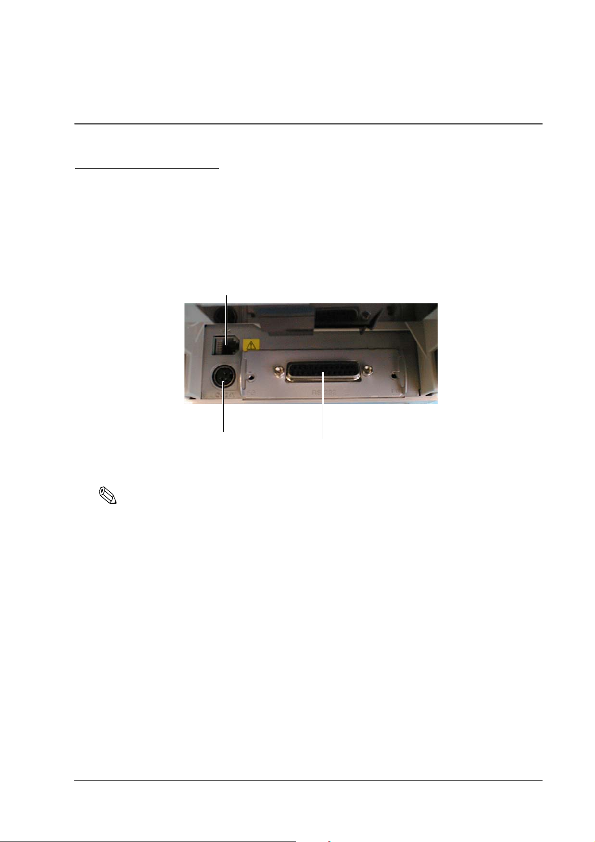
TM-L90/TM-L90 Peeler Model Technical Reference Guide
Interface connector
Drawer kick connector
Power supply connector
Chapter 3
Connecting to the Host Computer and Options
3.1 Connecting the Cable
This printer has 5 types of interface, serial, parallel, USB, Ethernet, and wireless LAN. The method of
connecting such options as a customer display varies depending on the interface type. Note that some
interfaces do not accept specific connection methods.
All cables are connected to the connector panel located on the lower rear side of the printer.
Connector Panel
Note:
The figure above shows the connector panel for RS-232 interface model printer (TM-L90 other than 4**
models, TM-L90 Peeler other than 39* models). The shape of the interface connector varies according to the
type of interface used.
Be sure to turn off the power supply for both the printer and the host computer unit before connecting the
various cables.
Be sure to unplug the power cord before inserting or removing the interface board.
Connecting to the Host Computer and Options 63
Page 64

3.2 Connecting to the Host Computer
3.2.1 With the RS-232C Interface
When the TM printer is connected to a host PC with a serial interface, the following connection forms are
possible:
• Stand alone
• Pass-through
Connections of available serial cross cables are as follows:
The types of cable (Type A or B) varies depending on the combination of the operation method and the
handshake for the TM printer. You can operate the TM printer by a Windows driver, OPOS, or ESC/POS
commands. Xon/Xoff, DTR/DSR or RTS/CTS are available as handshake control. See tables in the
following sections for the cable type for each connection.
64 Connecting to the Host Computer and Options
Page 65

TM-L90/TM-L90 Peeler Model Technical Reference Guide
2
1
Application
control
TM side
control setting
Note:
Refer to Chapter 5 for the Windows driver, OPOS ADK, and ESC/POS commands. Refer to "Connecting the
Cable" on page 63 for the cable connection procedure.
DTR/DSR control is available for OPOS.
Xon/Xoff or CTS/RTS control is available for APD. When using APD in serial connection, read the Note in
"EPSON Advanced Printer Driver Support Environment" on page 85 that contains precautions for TrueType
font printing.
Direct Connection (Stand alone)
Both TM printer and DM-D are connected to the host PC directly via serial port or USB port. The
following table shows the application control and cable connection types.
Xon/Xoff
(except OPOS)
Xon/Xoff 1 Type A or B
2 DM-D500: A, B
Other DM-D: not available
DTR/DSR 1 — Type A or B Type B
2
— Type A or B Type B
DTR/DSR
(DOS, Windows
(only OPOS))
——
——
RTS/CTR
(DOS, Windows (hardware
control: Windows driver))
Connecting to the Host Computer and Options 65
Page 66

Pass-through Connections
TM printer is connected to DM-D via serial port and DM-D is connected to the host PC via serial port.
The following table shows the application control and cable connection types.
Application
control
TM side
control setting
Xon/Xoff Not available
DTR/DSR 1 — Type A or B Type B
Xon/Xoff
(except OPOS)
— Type A or B Type A or B
2
DTR/DSR
(DOS, Windows
(only OPOS))
——
RTS/CTR
(DOS, Windows (hardware control:
Windows driver))
Connection procedure
1. Press the connector on the end of the interface cable firmly onto the interface connector located on the
connector panel.
2. When using connectors equipped with screws, use the screws to tighten the connectors firmly in
place.
Tightening Screws
3. For interface cables equipped with a ground line, attach the ground line to the screw hole marked "FG"
on the printer.
4. Connect the other end of the interface cable to the host computer.
66 Connecting to the Host Computer and Options
Page 67

TM-L90/TM-L90 Peeler Model Technical Reference Guide
3.2.2 With the Parallel (IEEE1284) Interface
TM printer is connected to the host PC via parallel port mounting parallel interface board (UB-P**). DMD is connected to the host PC via serial port or USB port.
Connecting to the Host Computer and Options 67
Page 68

Connection procedure
1. Press the connector on the end of the interface cable firmly onto the interface connector located on the
connector panel.
2. Press down the clips on either side of the connector to lock it in place.
3. For interface cables equipped with a ground line, attach the ground line to the screw hole marked "FG"
on the printer.
4. Connect the other end of the interface cable to the host computer.
3.2.3 With the USB Interface
A USB interface TM printer is connected to the host PC via USB. The second TM printer can be connected
via a self-powered USB hub from the printer connected to the host PC.
*1 Only the printer with the USB hub function allows another TM printer to be connected using a USB
cable.
*2 Epson does not supply the port driver or similar program necessary to control the USB interface printer
with the ESC/POS commands. Control it with the driver (APD, OPOS).
Connection procedure
1. Attach the locking wire saddle at the location shown in figure below.
2. Hook the USB cable through the locking wire saddle as shown in the figure below.
68 Connecting to the Host Computer and Options
Page 69

TM-L90/TM-L90 Peeler Model Technical Reference Guide
USB upstream connector
Locking wire saddle
USB cable
DM connector
USB downstream connector
(Not all models)
Control panel (USB model)
Note:
Hooking the USB cable through the locking wire saddle as shown in figure below will prevent the cable
from coming unplugged.
Attaching Locking Wire Saddle
3. Connect the USB cable from the host computer to the USB upstream connector.
4. For models that have the UB-U** installed, a maximum of two USB devices can be connected to the
USB downstream connector.
Note:
The hub installed in the USB model's control panel is a bus power-supply hub. Therefore, it is important
to note that bus power supply hubs (including other USB models) and bus power supply functions with
100 mA or more consumption current cannot be connected directly to the printer.
Note:
To use USB model TM printer, you need to install the USB device driver on host computer after
connecting TM printer to the host computer. For information on how to obtain the required device
drivers and their installation procedures, contact Epson or your dealer.
Note:
The connector panel varies depending on the models.
If you connect a customer display (DM-D), set the DIP switch settings as follows. For details, see the User’s
Manual packed with your customer display.
Note:
TM-L90 other than 4** models or TM-L90 Peeler other than 39* models have the DIP switches. TM-L90 4**
models or TM-L90 Peeler 39* models do not have the DIP switches; however, various functions can be set
with memory switches. For detailed information about the memory switches, see "Memory Switch Settings"
on page 42.
Connecting to the Host Computer and Options 69
Page 70

<Example>
10BASE-T/100BASE-TX
Item Selection
Transmission setting Transmission speed 19200 bps
Parity None
Data word length 8 bits
Before turning on the printer, be sure to turn on the customer display (DM-D). If you reverse the order,
the customer display will not be recognized correctly.
To satisfy the EMI standard, be sure to mount the ferrite core on the display module cable. To mount the
ferrite core, put the display module cable into the ferrite core.
3.2.4 With the Ethernet Interface (TM-L90 only)
TM printer with the Ethernet interface is connected to a network with the Ethernet cable via a Hub.
70 Connecting to the Host Computer and Options
Note:
The Ethernet interface TM printer does not accept a customer display (DM-D). Connect the customer display
to a POS terminal or appropriate equipment other than the printer.
Note:
When controlling the printer with OPOS, it is necessary to use exclusive control. Therefore, when using 1
printer with several PCs, it is necessary to take into account application programming whereby a PC that
already has the exclusive right must release it, then another PC must claim it.
Page 71

TM-L90/TM-L90 Peeler Model Technical Reference Guide
Access point
Modular cable
TM-L90
Cash drawer
Connection procedure
CAUTION:
Connecting devices directly to LAN cables that are installed outdoors will expose them to damage from
power surges caused by lightning and other inductive sources. It is best to make sure that devices without
proper surge protection are cushioned by being connected through devices that do have surge protection.
Otherwise, it is better not to connect them to outdoor lines.
Never attempt to connect the customer display cable, drawer kick cable or the standard telephone line cable
to the 10BASE-T/100BASE-TX Ethernet connector.
1. Confirm that the power supplies for both the printer and the host computer have been turned off.
2. Connect the 10BASE-T/100BASE-TX cable to the 10BASE-T/100BASE-TX Ethernet connector by
pressing firmly until the connectors click.
Note:
For the various methods of setting the Ethernet interface, refer to the Technical Reference Guide for the
Ethernet interface board.
3.2.5 With the Wireless LAN Interface
For details on how to set up a wireless LAN interface, see the Technical Reference Guide for the interface
board or the wireless LAN interface unit.
Connecting to the Host Computer and Options 71
Page 72

3.3 Connecting the Cash Drawer
Drawer kick connector
CAUTION:
• Specifications of drawers differ depending on makers or models. When you use a drawer
other than specified, make sure its specification meets the following conditions.
Otherwise, devices may be damaged.
* The load, such as a drawer kick-out solenoid, must be connected between pins 4 and 2 or pins 4 and
5 of the drawer kick connector.
* When the drawer open/close signal is used, a switch must be provided between drawer kick
connector pins 3 and 6.
* The resistance of the load, such as a drawer kick-out solenoid, must be 24 Ω or more or the input
current must be 1 A or less.
* Be sure to use the 24 V power output on drawer kick connector pin 4 for driving the equipment.
• Use a shield cable for the drawer connector cable.
• Two driver transistors cannot be energized simultaneously.
• Leave intervals longer than 4 times the drawer driving pulse when sending it continuously.
• Be sure to use the printer power supply (connector pin 4) for the drawer power source.
• Do not insert a telephone line into the drawer kick connector.
Doing so may damage the telephone line or printer.
1. Connect the drawer cable to the drawer kick connector (labeled DK) on the connector panel.
Note:
The connector panel varies depending on the models.
72 Connecting to the Host Computer and Options
Page 73

TM-L90/TM-L90 Peeler Model Technical Reference Guide
6 5 4 3 2 1
Adaptable Connector
Modular connector RJ12
Pin assignments
Pin number Signal name Direction
1 Frame GND -
2 Drawer kick drive signal 1 Output
3 Drawer kick open/close signal Input
4 +24 V -
5 Drawer kick drive signal 2 Output
6Signal GND -
3.3.1 Setting the internal buzzer (for models with an
internal buzzer)
Models with the buzzer function can beep the buzzer when the drawer is opened, by setting the properties
of the driver or outputting a pulse signal by a command. The internal buzzer cannot change the buzzer
volume and sound pattern but can change the buzzer frequency. When using the internal buzzer, you need
to enable the internal buzzer with the memory switch. The buzzer setting is performed by setting the
memory switches for the buzzer and specifying connector pin numbers to which a command outputs a
pulse signal, as shown in the table below. For information about the memory switches, see "Memory
Switch Settings" on page 42.
Memory switch Specified connector pin ON OFF Initial setting
Buzzer frequency (Pulse 1) Drawer kick connector pin 2 Buzzer beeps. Buzzer does not
beep.
Buzzer frequency (Pulse 2) Drawer kick connector pin 5 Buzzer beeps. Buzzer does not
beep.
OFF
ON
CAUTION:
Since the buzzer drive signal and the cash drawer drive signal are common in the printer, do not use the
same connector pin numbers to output the signal for the buzzer and the cash drawer.
Note:
For detailed information about ESC/POS commands, see the ESC/POS Command Reference. For details
on how to obtain this manual, see "Introduction of Control Methods" on page 83.
For detailed information about the driver control, see the manual for each driver.
Connecting to the Host Computer and Options 73
Page 74

74 Connecting to the Host Computer and Options
Page 75

TM-L90/TM-L90 Peeler Model Technical Reference Guide
Chapter 4
Setting/Checking Modes
4.1 Setting/Checking Modes of TM-L90 4** models, TM-L90 Peeler 39* models
Besides the ordinary print mode, the printer has the following modes to set or check settings of the printer.
❏ Self-test Mode
❏ NV Graphics Information Print Mode (page 77)
❏ Memory Switch Setting Mode (page 78)
❏ Hexadecimal Dump Mode (page 79)
The self-test mode or hexadecimal dumping mode is selected depending on the operation performed
when the power is turned on.
NV graphic information print mode and the memory switch setting mode are selected depending on the
FEED button operation performed during a self-test.
Close the roll paper cover, and turn on the printer while pressing the FEED button.
Self-test
Briey press the FEED button. Hold down the FEED button.
Continuing the self-test
Press the FEED button once briey and
then hold it down.
NV Graphics Information Print
Open the roll paper cover, and turn on the printer while pressing the FEED
button, and then close the roll paper cover.
(For Peeler Models only) Load paper in the paper path, and then press the FEED
button.
Hexadecimal Dumping
Mode selection guide
Press the FEED button twice briey and
then hold it down.
Memory Switch Setting
Setting/Checking Modes 75
Page 76

In 1 and 2, the following guidances are printed, the PAPER OUT LED flashes, and instructs the user's
operations.
1. Continuing self-test guidance 2. Mode selection guidance
4.1.1 Self-test Mode
You can check the following items using the self-test.
❏ Firmware version
❏ Interface type
❏ Receive buffer size
❏ BUSY condition
❏ Resident font
❏ Whether or not there are auto carriage returns
❏ Setting status of the interface reset signal
❏ Print density
❏ Power-on notification setting
❏ Paper width setting
❏ Paper type
❏ All types of sensor thresholds
❏ Print speed setting
❏ Maintenance counter information (head running length, number of times of autocutting)
76 Setting/Checking Modes
Page 77

TM-L90/TM-L90 Peeler Model Technical Reference Guide
❏ Memory switch settings
Follow the steps below.
1. Close the roll paper cover.
2. Turn on the power while pressing FEED button. Keep pressing the button until the ERROR LED
comes on.
After printing the current status, a Continuing self-test guidance is printed, and the PAPER OUT LED
flashes.
3. Briefly press the FEED button (less than one second) to continue the self-test.
If the test does not continue, turn off the power.
When the self-test continues, rolling printing is performed with the loaded text.
After "*** completed ***" is printed, the printer initializes and switches to standard mode.
4.1.2 NV Graphics Information Print Mode
You can confirm the following information with this mode:
❏ Capacity of the NV graphics
❏ Used capacity of the NV graphics
❏ Unused capacity of the NV graphics
❏ Number of NV graphics that are registered
❏ Key code, number of dots in X direction, number of dots in Y direction, number of colors to be
defined.
❏ NV graphics data
Follow the steps below.
1. Close the roll paper cover.
2. Turn on the power while pressing FEED button. Keep pressing the button until the ERROR LED
comes on.
After printing the current status, a Continuing self-test guidance is printed, and the PAPER OUT LED
flashes.
3. Hold down the FEED button (for at least one second) to shift to Mode selection.
Mode selection guidance is printed, and the PAPER OUT LED flashes.
4. After briefly (less than one second) pressing the FEED button once, hold it down for at least one
second, to print the NV graphics information.
Setting/Checking Modes 77
Page 78

After information printing, the Mode selection guidance is printed again.
5. To finish, turn off the power, or select "Exit and Reboot Printer".
4.1.3 Memory Switch Setting Mode
Use the following procedure to start this mode.
1. Close the roll paper cover.
2. Turn on the power while pressing FEED button. Keep pressing the button until the ERROR LED
comes on.
After printing the current status, a Continuing self-test guidance is printed, and the PAPER OUT LED
flashes.
3. Hold down the FEED button (for at least one second) to shift to Mode selection.
Mode selection guidance is printed, and the PAPER OUT LED flashes.
4. After briefly (less than one second) pressing the FEED button twice, hold it down for at least one
second, and then select memory switch setting mode (Customize Value Settings).
A guidance for the Memory switch setting mode is printed, and the PAPER OUT LED flashes.
TM-L90 TM-L90 Peeler
5. After briefly pressing the FEED button (less than one second) for the number of times shown in the
print result, hold down the button for more than one second, and then select the setting items.
78 Setting/Checking Modes
Page 79

TM-L90/TM-L90 Peeler Model Technical Reference Guide
The setting selected as the setting item, the current settings and initial settings are printed.
Depending on the setting item, you may need to continue making the setting item before the settings
are printed.
See "Setting items for Memory Switch Setting Mode" on page 119 for setting items and settings.
6. Select a setting by briefly pressing the FEED button (less than one second) for the number of times
applicable to the setting, and then hold down the button for more than one second to confirm your
selection.
After saving the settings, a guidance for the Memory switch setting mode is printed, and the PAPER
OUT LED flashes.
7. To close Memory switch setting mode, turn off the printer, or select "Exit" to return to Mode selection
guidance, and then select "Exit and Reboot Printer".
Note:
❏
To select 0 as the item number, hold down the FEED button until printing starts.
❏
If the button is pressed a number of times that is not displayed by the guidance, the operation is invalid
and the same guidance is printed.
4.1.4 Hexadecimal Dump Mode
TM printer can print the data transmitted from the host computer in hexadecimal numbers and in their
corresponding characters. This is called hexadecimal dump mode, which allow you to make sure the
transmission is correct by comparing the printed result with the programs.
Use the following procedure to output a hexadecimal dump.
1. For TM-L90, open the roll paper cover.
For TM-L90 Peeler, open the peeler cover and the roll paper cover.
2. Turn on the power while pressing FEED button inside the printer. Keep pressing the button until the
ERROR LED comes on.
3. For TM-L90, close the roll paper cover.
For TM-L90 Peeler, close the roll paper cover, and then after loading paper in the paper path, press the
paper feed switch.
Data received after this is printed in hexadecimal numbers and their corresponding characters.
4. When printing stops, turn off the power or press the FEED button three times or send a reset signal
from the interface.
Note:
Do not use this mode when using OPOS. To do so will cause continuous polling, ending in undesirable
results.
Setting/Checking Modes 79
Page 80

4.2 Setting/Checking Modes of TM-L90 other than 4** models, TM-L90 Peeler other than 39* models
Besides the ordinary print mode, the printer has the following modes to set or check settings of the printer.
❏ Self-test Mode
❏ Memory Switch Setting Mode (page 81)
❏ Hexadecimal Dump Mode (page 82)
The mode is selected depending on the operation performed when turning on the printer.
Close the roll paper cover, and turn on the printer while pressing the FEED button.
Self-test
Open the roll paper cover, and turn on the printer while pressing the FEED button, and then
press the FEED button twice and close the roll paper cover.
(For Peeler Models only) Load paper in the paper path, and then press the FEED button.
Open the roll paper cover, and turn on the printer while pressing the FEED button, and then
(For Peeler Models only) Load paper in the paper path, and then press the FEED button.
4.2.1 Self-test Mode
You can check the following items using the self-test.
❏ Firmware version
❏ Interface type
❏ Receive buffer size
❏ BUSY condition
❏ Resident font
Memory Switch Setting
close the roll paper cover.
Hexadecimal Dumping
❏ Whether or not there are auto carriage returns
❏ Power-on notification setting
❏ Print density
❏ Setting status for power ON
80 Setting/Checking Modes
Page 81

TM-L90/TM-L90 Peeler Model Technical Reference Guide
❏ Paper width setting
❏ Paper type
❏ All types of sensor thresholds
❏ Print speed setting
❏ Dip switch settings
❏ Memory switch settings
Follow the steps below.
1. Close the roll paper cover.
2. Turn on the power while pressing FEED button. Keep pressing the button until the ERROR LED
comes on.
After printing the current status, a Continuing self-test guidance is printed, and the PAPER OUT LED
flashes.
3. Briefly press the FEED button (less than one second) to continue the self-test.
If the test does not continue, turn off the power.
When the self-test continues, rolling printing is performed with the loaded text.
After "*** completed ***" is printed, the printer initializes and switches to standard mode.
4.2.2 Memory Switch Setting Mode
Use the following procedure to start this mode.
1. For TM-L90, open the roll paper cover.
For TM-L90 Peeler, open the peeler cover and the roll paper cover.
2. Turn on the power while pressing FEED button inside the printer. Keep pressing the button until the
ERROR LED comes on.
3. Press the FEED button twice.
4. For TM-L90, close the roll paper cover.
For TM-L90 Peeler, close the roll paper cover, and then after loading paper in the paper path, press the
paper feed switch.
The printer will print out a guidance and then enter the Memory Switch Setting Mode.
5. Follow the guidance to use the mode.
See the "Setting items for Memory Switch Setting Mode" on page 119 for setting items and settings.
Setting/Checking Modes 81
Page 82

4.2.3 Hexadecimal Dump Mode
TM printer can print the data transmitted from the host computer in hexadecimal numbers and in their
corresponding characters. This is called hexadecimal dump mode, which allow you to make sure the
transmission is correct by comparing the printed result with the programs.
Use the following procedure to output a hexadecimal dump.
1. For TM-L90, open the roll paper cover.
For TM-L90 Peeler, open the peeler cover and the roll paper cover.
2. Turn on the power while pressing FEED button inside the printer. Keep pressing the button until the
ERROR LED comes on.
3. For TM-L90, close the roll paper cover.
For TM-L90 Peeler, close the roll paper cover, and then after loading paper in the paper path, press the
paper feed switch.
Data received after this is printed in hexadecimal numbers and their corresponding characters.
4. When printing stops, turn off the power or press the FEED button three times or send a reset signal
from the interface.
Note:
Do not use this mode when using OPOS. To do so will cause continuous polling, ending in undesirable
results.
82 Setting/Checking Modes
Page 83

TM-L90/TM-L90 Peeler Model Technical Reference Guide
Chapter 5
Application Development Information
This chapter introduces how to control this printer and the information useful for development of
applications using this printer.
5.1 Introduction of Control Methods
The TM printer can print and be controlled by any of the following three methods.
1. Windows printer driver (EPSON Advanced Printer Driver)
2. EPSON OPOS ADK
3. ESC/POS commands
Depending on the driver and interface used, the IP setup tool for Ethernet specifications, USB device
driver, printing logo registration utility (TMFlash logo utility), etc. are available. Get the latest information
from the following URL.
For customers in North America, go to the following web site:
www.epson.com/support/ and follow the on-screen instructions.
For customers in other countries, go to the following web site:
www.epson-biz.com/?service=pos
For detailed information about the ESC/POS commands, see the ESC/POS Command Reference. You can
view this guide by accessing the URL described in the Introduction of Control Methods section with a user
ID that has been registered as an account.
5.1.1 Windows Driver (EPSON Advanced Printer Driver)
EPSON Advanced Printer Driver is a Windows driver for TM printers.
5.1.1.1 EPSON Advanced Printer Driver Overview
EPSON Advanced Printer Driver has the following features.
❏ Supplies the Windows printer driver for TM printers to enable printing from a general Windows
application.
❏ Can execute POS printer-specific functions such as paper cutting and drawer opening.
❏ Can print the printer resident font by selecting the font type.
❏ Can get the printer status using programming languages such as VB via Status API. This uses the
bidirectional communication of the TM printer in the Windows standard printer driver operation
environment.
Note:
Status API is the printer control API supplied originally by Epson. This can be used to get the printer status
and send ESC/POS commands.
Application Development Information 83
Page 84

5.1.1.2 EPSON Advanced Printer Driver Contents
The installer automatically judges the target PC environment and automatically installs the DLL and
software components necessary for operation. You can select the drivers, sample programs, and manuals
to be installed.
Drivers
You can select the driver according to the purpose of use. (Drivers can be installed simultaneously.)
They include smoothing, continuous printing, cutting method option and other functions.
❏ With TM-L90
• Receipt: For receipt printing
• Reduce 35: A4 vertical size can be reduced 35% to enable printing on receipts of 80 mm width.
• Label: For label printing
❏ With the TM-L90 Peeler Model
• Receipt: For continuous printing
• Label: For printing label paper
Sample programs
Sample programs in Visual Basic and Visual C++ to use Status API can be installed.
Manuals
The following manuals can be installed.
❏ With TM-L90
• Driver: User's Manual
• Status API: Reference Manual
❏ With the TM-L90 Peeler Model
• User's Guide (Developer's Guide)
84 Application Development Information
Page 85

TM-L90/TM-L90 Peeler Model Technical Reference Guide
5.1.1.3 EPSON Advanced Printer Driver Support Environment
Supported interfaces
• Serial, Parallel, USB, Ethernet, Wireless LAN
Supported OSs (with confirmation of system operation)
For details on the supported operating systems, see the release note of the driver for the latest information.
Supported development languages
For details on the supported development languages, see the release note of the driver for the latest
information.
Supported devices
(Refer to the release note of the driver for details of available equipment.)
• Epson receipt printer
• Epson customer display
•Epson cash drawer
Note:
The USB interface models require USB device driver. The Ethernet or Wireless LAN interface models require
IP setting utility. For the details, refer to the packaged APD manual.
When the TM-L90 is connected via a serial interface, it is recommended to use the printer resident font since
use of the TrueType font will decrease printing speed due to the transfer speed of the serial interface. For how
to use the resident font, refer to the PDF User's Manual of APD.
The other interfaces (parallel, USB, Ethernet) do not pose problems in terms of the transfer speed but may
have some influence on customer applications. In that case, use the printer resident font. When OPOS is
used, this problem does not arise because only the printer resident font is available.
5.1.1.4 Driver Information and Download Destination
See "Introduction of Control Methods" on page 83.
5.1.2 EPSON OPOS ADK
EPSON OPOS ADK supports the development environment required for OPOS application development
by OPOS Control proposed by the OLE for Retail POS (hereafter OPOS) Technology Association to
supply the OPOS-compliant printer driver (OCX).
Use this control method to develop an OPOS-compliant application. EPSON OPOS ADK has the
following features.
❏ EPSON OPOS ADK totally supports the development environment required for OPOS application
development for customers, including not only OPOS Control (CO + SO) proposed by the OPOS
Association, but also the contents necessary for development, ranging from the installers and setup
utilities to sample programs and manuals, the function to get a log for debugging, and silent
installation that realizes ease of installation to a target PC.
Application Development Information 85
Page 86

❏ EPSON OPOS ADK enables you to reduce the man-hours for the application development since it
includes the following functions that application developers have to consider. The functions are:
Support with the Epson-original Direct IO with a parameter, the power-on notification, and off-line
buffer clear processing.
Note:
For detailed information on the API functions, see the UnifiedPOS specification available at the following
web site:
https://www.omg.org/retail/unified-pos.htm
86 Application Development Information
Page 87

TM-L90/TM-L90 Peeler Model Technical Reference Guide
5.1.2.1 EPSON OPOS ADK (OPOS Control) Overview
OPOS Control included with EPSON OPOS ADK has the following features.
❏ Supplies CO for each device class and SO for Epson devices.
❏ Direct IO with parameters available.
• Gets the maintenance counter value of the printer.
• NVRAM-registered electronic logo (bit image) printing, etc. (For the electronic logo, refer to
"Electronic Logo Registration Utility for NVRAM" on page 89.)
❏ Power-on notification function (at power-on, this function automatically restores the printer to the
state prior to the power-off)
❏ Offline buffer clear processing (clears the print buffer contents in the offline mode)
❏ Debugging function (trace function)
• Gets a log between the application and CO (target: Used API and its return value)
• Device status getting log (gets the offline and error factors that actually occurred in the devices)
and so on.
5.1.2.2 EPSON OPOS ADK Contents
The installer of EPSON OPOS ADK Ver. 2.10 or later has the silent installation function, which can install
the OPOS environment without a user interface, to facilitate installation. With the installer, the following
OPOS-compliant OPOS Control for Epson devices, manuals, various utilities and sample programs can be
installed.
❏ OPOS Control for Epson devices
Header files for CO, SO, C++, header file for VB, TLB file of CO, device information file, etc. can be
installed.
❏ Manuals
• User's Guide (Environment construction manual: Installation/uninstallation, various utility using
methods)
• Application Development Guide (Manual for OPOS-compliant application developer: Common
manual, Each device manual)
Application Development Information 87
Page 88

❏ Utilities packed with various drivers
• SetUpPOS Utility
Equipment and connection ports can be selected, and various settings can be made.
(Paper size, print waiting time setting, etc.)
• TM Flash logo utility
A bitmap file can be registered to the printer or customer display, for example.
• USB device driver
Driver necessary to connect the USB interface printer.
• Sample programs
Sample programs in VB, VC++ can be installed.
5.1.2.3 EPSON OPOS ADK Support Environment
Supported interfaces
• Serial, Parallel, USB, Ethernet, Wireless LAN
Supported OSs (with confirmation of system operation)
For details on the supported operating systems, see the release note of the driver for the latest information.
Supported development languages
For details on the supported development languages, see the release note of the driver for the latest
information.
5.1.2.4 Driver Information and Download Destination
See "Introduction of Control Methods" on page 83.
5.1.3 ESC/POS Commands
Printing/control via ESC/POS commands is a method proposed by Epson to directly control the TM
printer using ESC/POS commands. The printer can be controlled directly by sending ESC/POS
commands from an application to the printer. For detailed information on the ESC/POS commands, see
the ESC/POS Command Reference. For details on how to obtain this manual, see "Introduction of Control
Methods" on page 83.
Note:
The printer of Ethernet specifications requires the IP setup utility separately. For details on how to obtain the
utility, see "Various Utilities" on page 89.
88 Application Development Information
Page 89

TM-L90/TM-L90 Peeler Model Technical Reference Guide
5.1.4 Various Utilities
We provide the utilities as described below. Get the utilities from the following URL.
For customers in North America, go to the following web site:
www.epson.com/support/ and follow the on-screen instructions.
For customers in other countries, go to the following web site:
www.epson-biz.com/?service=pos
5.1.4.1 Address Setup Utility for Ethernet Interface (for UB-E**)
The utility, which sets an IP address to a 10BASE-T/100BASE-TX Ethernet interface for TM printer, and
its detailed manual for developers are available. The customer who purchases the Ethernet interface TM
printer needs this utility.
5.1.4.2 Electronic Logo Registration Utility for NVRAM
This utility is designed to register a logo to the NVRAM (non-volatile memory) built in the printer. Using
this utility saves shop logos to the NVRAM to increase logo printing speed.
5.1.4.3 Memory Switch Setting Utility
This utility is designed to perform the memory switch-related functions of the TM printer easily.
❏ You can execute a communication test and self-test.
❏ You can set the switches, etc. (such as the memory switches and customized values).
❏ You can set the paper layout for the TM-L90.
5.1.4.4 USB Interface ID Code Rewrite Utility
This utility is designed to edit the identification code of a USB interface according to the purpose of the
user of USB interface TM printer. When you do not want to change the USB port setting of the driver after
replacement of the TM printer, you do not need to change the port number by setting the same IP.
5.2 Sensors
5.2.1 Paper Sensors
The printer has two paper sensors.
5.2.1.1 Roll paper near-end sensor
The roll paper near-end sensor is to detect the condition when the remaining amount of the paper is
getting low and it is located on the roll paper supply unit. It detects the near-end of the roll paper by
detecting the roll paper diameter. You can adjust the sensor position. See page 25 for details for
adjustment.
The normal printing task will be performed even in the near-end status.
Note:
The detecting the near-end status of the sensor does not necessarily indicate the complete end of the roll
paper. Use the sensor as an indication of replacing a roll paper.
Application Development Information 89
Page 90

5.2.1.2 Roll Paper End Sensor
The roll paper end sensor is located in the paper path. It detects the presence of paper through the roll
paper in the paper path.
When there is no paper in the path (paper end status), the ERROR LED and the PAPER OUT LED indicator
will light and it will be in the error status.
If the sensor detects the roll paper end, the printer will stop printing even in the process of printing. It is
recommended that you mainly use the roll paper near-end sensor and use the roll paper end sensor
secondarily.
5.2.2 Printer Cover Sensor
5.2.2.1 Roll Paper Cover Open Sensor
The cover-open sensor monitors the roll paper cover. When the sensor detects an open cover while
printing, the printer stops printing immediately and automatically goes offline. Depending on the Msw 88 setting, an open cover error is handled as either a recoverable error or unrecoverable error as described
below.
❏ Msw 8-8 off: Automatically recoverable error. The ERROR LED flashes. When
the printer cover is closed, the ERROR LED goes off, and the
printer goes online and starts printing at the beginning of the line it
was printing when the cover was opened.
❏ Msw 8-8 on: (Default) Recoverable error. The ERROR LED flashes. Since the ERROR LED
still flashes after the cover is closed, send the error recovery
command to recover from the error.
When the printer recovers, it feeds paper to take up the slack, and starts printing from the beginning of the
line where the error occurred. In this case, double printing and printing position shift may occur. It is
recommended to set the memory switch Msw 8-8 to ON, clear the printer buffers by a command from the
driver, and resend the print data.
Whether the cover is open or not does not affect the status reported by the roll paper end sensor.
Note:
When OPOS or Advanced Printer Driver is used, do not change the default setting of the memory switch.
5.2.2.2 Offline
This printer is not equipped with an online/offline switch. The printer goes offline under the following
conditions automatically.
• When the power is turned on (including reset using the interface) and while the printer is ready to
receive data.
• During the self test.
• When the roll paper cover is open.
• During paper feeding using the FEED button.
90 Application Development Information
Page 91

TM-L90/TM-L90 Peeler Model Technical Reference Guide
• When the printer stops printing due to a paper-end (in cases when an empty paper supply is
detected by roll paper end detector or when it has been set to stop printing by the driver when the
roll paper near-end sensor detects a paper end.)
• When an error has occurred.
• During macro executing standby status.
• Waiting for FEED status when inserting the roll paper (to complete the task of inserting the roll
paper by pressing the FEED button)
Note:
The off-line status also happens infrequently when the pulse of the drawer kick is sent.
5.2.2.3 Busy state
Selecting conditions that invoke a BUSY State
The conditions that invoke a BUSY condition are selected with memory switch setting mode or memory
switch Msw1-3 as follows.
❏ When the receive buffer is full
❏ When the receive buffer is full or the printer is off-line
Note:
In either case indicated above, it will be a BUSY status when turning on the power (including resetting with
the interface), while the printer is in the state of receiving data and when executing a self-testing.
You do not need to change this item during the use of OPOS or Advanced Printer Driver.
Printer BUSY conditions and the Msw1-3 status
Memory switch Msw 1-3 state
Printer status
Offline During the period from when the power is turned on
(including resetting using the interface) to when the
printer is ready to receive data.
During the self test. BUSY BUSY
When the cover is open. - BUSY
During paper feeding using the paper feed button. - BUSY
When the printer stops printing due to a paper-end.
(only when the roll paper is not present)
When an error has occurred. - BUSY
ON OFF
BUSY BUSY
-BUSY
When the receive buffer becomes full. BUSY BUSY
Application Development Information 91
Page 92

5.2.2.4 Receive buffer
The capacity of the receive buffer is set using memory switch setting mode or memory switch Msw1-2.
The definition of a receive buffer full is described in the following table.
The printer ignores the data received when the remaining space in the receive buffer is 0 bytes.
Memory switch
Msw1-2
ON 45 bytes From when the remaining space in the receive buffer drops to 16 bytes, to
OFF 4 KB From when the remaining space in the receive buffer drops to 128 bytes, to
Receive buffer
capacity
Buffer full definition
when the space increase to 26 bytes.
when the space increase to 256 bytes.
Note:
When using OPOS or Advanced Printer Driver, you don't need to change the receive buffer.
5.2.3 Label Peeling Sensor (Peeler Specification Only)
This detects whether or not there is a peeled label. If a label is removed, the next label is moved to the
printing start position.
Note:
If the printer is used in a location with direct sunlight, even when a label is removed, it may be determined as
being present due to misdetection, and the printer continues waiting for label removal status. In this case,
press the FEED button once to return the paper to the next label printing start position.
5.3 Barcode Printing
The TM-L90 / TM-L90 Peeler Model can print the types of barcode shown below.
UPC-A, UPC-E
JAN 8 (EAN 8), JAN 13 (EAN 13)
CODE 39
ITF (Interleaved 2 of 5)
CODABAR (NW-7)
CODE 93
CODE 128
GS1-128*
GS1 DataBar Omnidirectional*
GS1 DataBar Truncated*
GS1 DataBar Stacked*
GS1 DataBar Stacked Omnidirectional*
GS1 DataBar Limited*
GS1 DataBar Expanded*
GS1 DataBar Expanded Stacked*
PDF417
MaxiCode
92 Application Development Information
Page 93

TM-L90/TM-L90 Peeler Model Technical Reference Guide
QRCode
Composite Symbology*
DataMatrix*
*: Available only for TM-L90 4** models or TM-L90 Peeler 39* models
Refer to each document of OPOS, Printer Driver or ESC/POS commands for the setting/printing
procedures of each barcode.
5.4 CODE 128 Barcode
The CODE 128 barcode allows a single barcode character to represent one character of a full-ASCII 128character set or two-digit number from among the combinations of 103 different barcode characters and
three different code sets.
• Code set A: Can represent ASCII characters 00H to 5FH.
• Code set B: Can represent ASCII characters 20H to 7FH.
• Code set C: One character can represent a two-digit number (100 numbers from 00 to 99).
In addition to the above characters, CODE 128 also provides the following special characters.
• Shift character (SHIFT)
The code set A handles the character right after SHIFT as a character of the code set B. The code
set B handles the character right after SHIFT as a character of the code set A. SHIFT cannot be
used in the code set C.
• Code set selection character (CODE A, CODE B, CODE C)
Changes the subsequent code set to A, B or C.
• Function character (FNC1, FNC 2, FNC3, FNC4)
The purpose of the function character changes depending on the application. The code set C
accepts only FNC1.
Application Development Information 93
Page 94

Printable characters for code set A
Transmission data Transmission data Transmission data
Hexadecimal
characters
NUL 00 0 ( 28 40 P 50 80
SOH 01 1 ) 29 41 Q 51 81
STX 02 2 * 2A 42 R 52 82
ETX 03 3 + 2B 43 S 53 83
EOT 04 4 , 2C 44 T 54 84
ENQ 05 5 - 2D 45 U 55 85
ACK 06 6 . 2E 46 V 56 86
BEL 07 7 / 2F 47 W 57 87
BS 08 8 0 30 48 X 58 88
HT 09 9 1 31 49 Y 59 89
LF 0A 10 2 32 50 Z 5A 90
VT 0B 11 3 33 51 [ 5B 91
FF 0C 12 4 34 52 \ 5C 92
CR 0D 13 5 35 53 ] 5D 93
SO 0E 14 6 36 54 ^ 5E 94
SI 0F 15 7 37 55 _ 5F 95
DLE 10 16 8 38 56 FNC1 7B,31 123,49
DC1 11 17 9 39 57 FNC2 7B,32 123,50
DC2 12 18 : 3A 58 FNC3 7B,33 123,51
DC3 13 19 ; 3B 59 FNC4 7B,34 123,52
DC4 14 20 < 3C 60 SHIFT 7B,53 123,83
NAK 15 21 = 3D 61 CODEB 7B,42 123,66
SYN 16 22 > 3E 62 CODEC 7B,43 123,67
ETB 17 23 ? 3F 63
CAN 18 24 @ 40 64
EM 19 25 A 41 65
SUB 1A 26 B 42 66
ESC 1B 27 C 43 67
FS 1C 28 D 44 68
GS 1D 29 E 45 69
RS 1E 30 F 46 70
US 1F 31 G 47 71
SP 20 32 H 48 72
! 21 33 I 49 73
" 22 34 J 4A 74
# 23 35 K 4B 75
$ 24 36 L 4C 76
% 25 37 M 4D 77
& 26 38 N 4E 78
' 27 39 O 4F 79
code
Decimal
code
characters
Hexadecimal
code
Decimal
code
characters
Hexadecimal
code
Decimal
code
94 Application Development Information
Page 95

TM-L90/TM-L90 Peeler Model Technical Reference Guide
Printable characters for code set B
Transmission data Transmission data Transmission data
Hexadecimal
characters
SP 20 32 H 48 72 p 70 112
! 21 33 I 49 73 q 71 113
" 22 34 J 4A 74 r 72 114
# 23 35 K 4B 75 s 73 115
$ 24 36 L 4C 76 t 74 116
% 25 37 M 4D 77 u 75 117
& 26 38 N 4E 78 v 76 118
' 27 39 O 4F 79 w 77 119
( 28 40 P 50 80 x 78 120
) 29 41 Q 51 81 y 79 121
* 2A 42 R 52 82 z 7A 122
+ 2B 43 S 53 83 { 7B,7B 123,123
, 2C 44 T 54 84 | 7C 124
_ 2D 45 U 55 85 } 7D 125
. 2E 46 V 56 86 — 7E 126
/ 2F 47 W 57 87 DEL 7F 127
0 30 48 X 58 88 FNC1 7B,31 123,49
1 31 49 Y 59 89 FNC2 7B,32 123,50
2 32 50 Z 5A 90 FNC3 7B,33 123,51
3 33 51 [ 5B 91 FNC4 7B,34 123,52
4 34 52 \ 5C 92 SHIFT 7B,53 123,83
5 35 53 ] 5D 93 CODEA 7B,41 123,66
6 36 54 ^ 5E 94 CODEC 7B,43 123,67
7 37 55 _ 5F 95
8 38 56 ` 60 96
9 39 57 a 61 97
: 3A 58 b 62 98
; 3B 59 c 63 99
< 3C 60 d 64 100
= 3D 61 e 65 101
> 3E 62 f 66 102
? 3F 63 g 67 103
@ 40 64 h 68 104
A 41 65 i 69 105
B 42 66 j 6A 106
C 43 67 k 6B 107
D 44 68 l 6C 108
E 45 69 m 6D 109
F 46 70 n 6E 110
G 47 71 o 6F 111
code
Decimal
code
characters
Hexadecimal
code
Decimal
code
characters
Hexadecimal
code
Decimal
code
Application Development Information 95
Page 96

Printable characters for code set C
Transmission data Transmission data Transmission data
Hexadecimal
characters
00 00 0 40 28 40 80 50 80
01 01 1 41 29 41 81 51 81
02 02 2 42 2A 42 82 52 82
03 03 3 43 2B 43 83 53 83
04 04 4 44 2C 44 84 54 84
05 05 5 45 2D 45 85 55 85
06 06 6 46 2E 46 86 56 86
07 07 7 47 2F 47 87 57 87
08 08 8 48 30 48 88 58 88
09 09 9 49 31 49 89 59 89
10 0A 10 50 32 50 90 5A 90
11 0B 11 51 33 51 91 5B 91
12 0C 12 52 34 52 92 5C 92
13 0D 13 53 35 53 93 5D 93
14 0E 14 54 36 54 94 5E 94
15 0F 15 55 37 55 95 5F 95
16 10 16 56 38 56 96 60 96
17 11 17 57 39 57 97 61 97
18 12 18 58 3A 58 98 62 98
19 13 19 59 3B 59 99 63 99
20 14 20 60 3C 60 FNC1 7B,31 123,49
21 15 21 61 3D 61 CODEA 7B,41 123,65
22 16 22 62 3E 62 CODEB 7B,42 123,66
23 17 23 63 3F 63
24 18 24 64 40 64
25 19 25 65 41 65
26 1A 26 66 42 66
27 1B 27 67 43 67
28 1C 28 68 44 68
29 1D 29 69 45 69
30 1E 30 70 46 70
31 1F 31 71 47 71
32 20 32 72 48 72
33 21 33 73 49 73
34 22 34 74 4A 74
35 23 35 75 4B 75
36 24 36 76 4C 76
37 25 37 77 4D 77
38 26 38 78 4E 78
39 27 39 79 4F 79
code
Decimal
code
characters
Hexadecimal
code
Decimal
code
characters
Hexadecimal
code
Decimal
code
96 Application Development Information
Page 97

TM-L90/TM-L90 Peeler Model Technical Reference Guide
5.5 Precautions for Two-Dimensional Code Printing
This printer can print two-dimensional codes. The following two-dimensional codes can be printed.
❏ PDF417
❏ QRCode
❏ MaxiCode
❏ Composite Symbology*
❏ DataMatrix*
*: Available only for TM-L90 4** models
Note the following for two-dimensional code printing.
❏ The two-dimensional code recognition ratio changes depending on the module width, print density,
environmental temperature, roll paper (thermal paper) type, reader performance, etc. Therefore, precheck the recognition ratio and set the operating conditions to satisfy the restrictions of the reader.
❏ For PDF417 (two-dimensional code) printing, it is recommended to set the height of one symbol to
three to five times greater than the module width. It is also recommended to set the overall height of
the code to more than 5 mm (approximately).
5.6 NV Memory
NV memory is embedded in the printer. Please use NV memory with attention to the following:
❏ The following restrictions apply when performing nonvolatile memory operations (including data
store and delete).
• The paper feed switch must not be used to feed paper.
• The real time command must not be executed.
• The ASB status will not be sent, even when the ASB function in ESC/POS command is set to
enable.
❏ The printer will sometimes enter the Busy state when data is being written to nonvolatile memory. It is
important not to send data from the host computer while the printer is in the Busy state as it will be
incapable of processing any received data.
❏ Frequent use of the functions for defining data to and deleting data from nonvolatile memory can
damage the memory. As a rule, in using the various commands to write to NV memory, avoid writing
more than an average of 10 times per day.
Application Development Information 97
Page 98

5.7 FAQ List
The questions shown in the list below begin with "Q" and their replies with "A"
1. Look through sentences beginning with "Q" to find information relating to your question or problem.
2. Then follow the instructions described in the "A" sentence below it.
Q: Print data dropout occurs.
A: Check the handshake process.
Data dropout can occur when the handshake between the host computer and the printer is not performed
correctly. This can result in errors related to print buffer capacity.
Confirmation procedure
Use the following steps to check the handshake process.
1. Select a comparatively large volume of data for printing and send it to the printer.
2. Enable the on-line state by opening the printer cover while the printer is printing.
3. Check the data send operation.
• If data send terminates: Handshake process is normal
• If data send continues: Handshake process is abnormal
4. In cases where the handshake process is found to be abnormal, follow the steps listed in Corrective
Procedure shown below and re-enter host unit and printer settings so that they match.
Corrective procedure
1. Confirm the serial communication cable.
Confirm the specification of cable connection. "Connecting the Cable" on page 63.
2. Confirm serial communication condition.
Confirm serial communication condition of printer and host.
Serial communication conditions
•Baud rate
•Parity
•Flow control
•Data length
Confirmation and setting of printer are as follows.
1. Confirm serial communication condition of the printer by self-test (See page 42).
98 Application Development Information
Page 99

TM-L90/TM-L90 Peeler Model Technical Reference Guide
2. Confirm DIP SW 1-2.
Printer serial communication condition can be set by DIP SW and memory switch. When the printer
is powered on, DIP SW 1-2 selects DIP SW setting or memory switch setting as initial communication
condition. Selected setting is printed by self-test.
DIP SW1-2 OFF: Used communication condition set by memory switch.
ON: Used communication condition set by DIP SW.
3. Set communication condition
When DIP SW1-2 is ON
Follow the procedure (page 40) and set.
When DIP SW1-2 is OFF
Follow the serial communication conditions (page 42). There are two ways to set it. Refer to "Memory
Switch Settings" on page 42 or "Memory Switch Setting Utility" on page 89.
Note:
TM-L90 4** models or TM-L90 Peeler 39* models do not have the DIP switches; however, various
functions can be set with memory switches. For detailed information about the memory switches, see
"Memory Switch Settings" on page 42.
Q: Drawer Kick does not operate properly.
A: Drawer specifications differ depending on the manufacturer and the part number.
Refer to "Connecting the Cash Drawer" on page 72 and check that the cash drawer meets the required
specifications.
Q: Unable to print a part of Page 0 (for example ) in Visual Basic.
A: When programming with Visual Basic, limitations prevent data from 81h through 9Fh and E0h through
FEh from being sent as characters. However, you can use the following procedure to send this data.
Dim Send_ data(0) As Byte
Send_data(0) = &h81 ’1 byte of sending data
MSComm1.Output = Send_data
Q: Does USB 2.0-compatible equipment accept the USB interface printer?
A: Yes, but note that the speed of communication between the USB2.0 equipment and the printer is “USB full
speed mode.”
Note:
USB2.0 defines three speeds: High speed (480 Mbps), Full speed (12 Mbps) and Low speed (1.5 Mbps). This
printer supports only Full speed (12 Mbps) and Low speed (1.5 Mbps).
Application Development Information 99
Page 100

100 Application Development Information
 Loading...