

Page 1
Technical Reference Guide
Describes the features of the product.
Describes the setup and installation of
the product and peripherals.
Describes the advanced usage of
the product.
Describes how to control the printer and gives
information useful for printer application development.
Describes the product specications,
interface specications, and character code.
Describes the basic handling of the printer.
Liner-Free Label Paper Model
Product Overview
Setup
Advanced Usage
Application Development
Information
Handling
Appendix
M00123002
Rev. C
Page 2

CAUTION
• No part of this document may be reproduced, stored in a retrieval system, or transmitted in any form or by any means,
electronic, mechanical, photocopying, recording, or otherwise, without the prior written permission of Seiko Epson
Corporation.
• The contents of this document are subject to change without notice. Please contact us for the latest information.
• While every precaution has been taken in the preparation of this document, Seiko Epson Corporation assumes no
responsibility for errors or omissions.
• Neither is any liability assumed for damages resulting from the use of the information contained herein.
• Neither Seiko Epson Corporation nor its affiliates shall be liable to the purchaser of this product or third parties for
damages, losses, costs, or expenses incurred by the purchaser or third parties as a result of: accident, misuse, or abuse of
this product or unauthorized modifications, repairs, or alterations to this product, or (excluding the U.S.) failure to strictly
comply with Seiko Epson Corporation’s operating and maintenance instructions.
• Seiko Epson Corporation shall not be liable against any damages or problems arising from the use of any options or any
consumable products other than those designated as Original Epson Products or Epson Approved Products by Seiko
Epson Corporation.
Trademarks
EPSON is a registered trademark of Seiko Epson Corporation.
Exceed Your Vision and ESC/POS are registered trademarks or trademarks of Seiko Epson Corporation.
Microsoft and Windows are registered trademarks of Microsoft Corporation in the United States and/or other countries.
Android™ is a trademark of Google LLC.
IOS is a trademark or registered trademark of Cisco in the U.S. and other countries and is used under license.
All other trademarks are the property of their respective owners and used for identification purpose only.
ESC/POS® Command System
EPSON ESC/POS is a proprietary POS printer command system that includes patented or patent-pending commands. ESC/
POS is compatible with most EPSON POS printers and displays.
ESC/POS is designed to reduce the processing load on the host computer in POS environments. It comprises a set of highly
functional and efficient commands and also offers the flexibility to easily make future upgrades.
©Seiko Epson Corporation 2019-2021.
Page 3
For Safety
Key to Symbols
The symbols in this manual are identified by their level of importance, as defined below. Read the following
carefully before handling the product.
You must follow warnings carefully to avoid serious bodily injury.
!WARN ING
Provides information that must be observed to prevent damage to the equipment or
!CAUTION
loss of data.
• Possibility of sustaining physical injuries.
• Possibility of causing physical damage.
• Possibility of causing information loss.
Provides information that must be observed to avoid damage to your equipment or a
malfunction.
Provides important information and useful tips.
Warnings
!WARN ING
• Do not cover the printer with cloth or place it in a poorly ventilated location.
• The internal temperature may increase, leading to fire.
• Keep the printer away from volatile substances, such as alcohol and thinner, and
fire. Failure to do so may result in electrical shock or fire.
• Shut down your equipment immediately if it produces smoke, a strange odor, or
unusual noise. Failure to do so may result in electrical shock or fire.
• If an accident occurs, turn off the power immediately and unplug the AC cable.
Then contact qualified service personnel.
• If foreign matter or liquid such as water spills into this equipment, do not continue
to use it. Continued use may result in electrical shock or fire.
• Immediately unplug the equipment and contact qualified service personnel.
• Do not disassemble the printer except for the locations indicated in the manual.
• Never attempt to repair this product yourself. Improper repair work can be
dangerous.
• Do not use the printer in a location where flammable gas, explosive gas, or similar
gas might exist in the air. Do not use aerosol sprayers containing flammable gas
inside or around this product. Doing so may cause fire.
• Do not connect cables in ways other than those indicated in this manual.
• Doing so may lead to fire. Doing so may also damage the connected equipment.
• Do not insert or drop metal or flammable objects into the printer from the
openings. Doing so may result in electrical shock or fire.
• Make sure to use this product at the specified voltage. Failure to do so may result in
fire or electrical shock.
3
Page 4

!WARN ING
• Check that the plug is clean before plugging it in. Failure to do so may result in
electrical shock or fire.
• Be sure to push the plug all the way in. Failure to do so may result in electrical
shock or fire.
• Do not use a damaged power cable. Doing so may result in electrical shock or fire.
• If the power cable is damaged, contact qualified service personnel.
• Do not place multiple loads on the power outlet. Overloading the outlet may lead
to fire.
• Be sure to disconnect the plug from the power outlet and clean the base of the
blades and the area between the blades. Leaving the plug inserted in the power
outlet for a long time may cause dust to stick to the base of blades, leading to fire.
• When you disconnect the plug from the power outlet, hold the plug and do not
pull the cable. Failure to do so may damage the cable or deform the plug, resulting
in electrical shock or fire.
• When handling the AC adapter, observe the instructions described below. Failure
to do so may result in electrical shock or fire.
* Avoid exposure to rain or water.
* Do not hang the adapter on the power cable.
* Avoid contact between a metal object such as a paper clip and the connector.
* Do not cover the adapter with a blanket or similar item.
• Do not insert a telephone line into the drawer kick connector. Doing so may
damage the telephone line or printer.
• Do not place the printer in a dusty or humid location. Doing so may result in
electrical shock or fire.
• Before relocating this product, turn off the power, disconnect the plug from the
power outlet, and make sure that all the cables are disconnected. Failure to do so
may result in electrical shock or fire.
4
Page 5

Cautions
!CAUTION
• Do not place/store the printer on an unsteady location or a location subject to the
vibration of other equipment. Otherwise, the product may break or cause injury if it
falls.
• Do not place heavy objects on top of this product. Never stand or lean on this
product. Otherwise, the product may fall or break and cause injury.
• When connecting cables or installing optional products, follow the procedures and
make sure that the cables and products are installed in the proper direction. Failure
to do so may cause injury.
• Follow the instructions in the manual for proper installation.
• While opening/closing the printer cover, keep your hands away from the joint
between the cover and the main body. Otherwise, your hand or finger may be
pinched and get injured.
• To ensure safety, unplug this product when leaving it unused for an extended
period.
• Do not touch the inside of the printer except for the locations indicated in the
manual. Doing so may result in electrical shock or burns.
• Observe the instructions below to prevent the power cable from being damaged.
• Do not modify or attempt to repair the cable
• Do not place any heavy object on top of the cable
• Avoid excessive bending, twisting, and pulling
• Do not place the cable near heating equipment
• Never insert or disconnect the power plug with wet hands. Doing so may result in
severe shock.
• Take care not to push your hand or finger against the manual cutter. Doing so may
injure your hand or finger.
* When you remove printed paper
* When you perform other operations such as loading/replacing roll paper
5
Page 6
Caution Labels
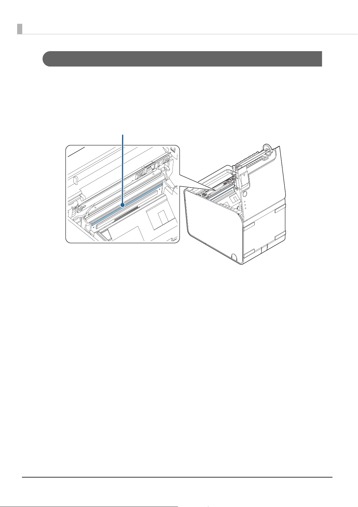
Thermal head
The caution labels on the product indicate the following precautions.
! K CAUTION:
Do not touch the thermal head during or immediately after use. After printing, the thermal head and its
surroundings can be very hot.
Restriction of Use
When this product is used for applications requiring high reliability/safety, such as transportation devices
related to aviation, rail, marine, automotive, etc.; disaster prevention devices; various safety devices, etc.; or
functional/precision devices, etc., you should use this product only after giving consideration to including
fail-safes and redundancies into your design to maintain safety and total system reliability.
Because this product was not intended for use in applications requiring extremely high reliability/safety,
such as aerospace equipment, main communication equipment, nuclear power control equipment, or
medical equipment related to direct medical care, etc., please make your own judgment on this product's
suitability after a full evaluation.
6
Page 7

About this Manual
Aim of the Manual
This manual provides developers/engineers with all the necessary information for design, development
and installation of a POS system, and also design and development of a printer application.
Manual Content
The manual is made up of the following sections:
Chapter 1 Product Overview
Chapter 2 Setup
Chapter 3 Advanced Usage
Chapter 4 Application Development Information
Chapter 5 Handling
Appendix Product Specifications
Specifications of Interfaces and Connectors
Character Code Tables
7
Page 8

Contents
■ For Safety ......................................................... 3
Key to Symbols..........................................................................3
Warnings......................................................................................3
Cautions.......................................................................................5
Caution Labels ...........................................................................6
■ Restriction of Use ............................................ 6
■ About this Manual........................................... 7
Aim of the Manual....................................................................7
Manual Content ........................................................................7
■ Contents........................................................... 8
Product Overview.......................11
■ Features ......................................................... 11
■ Product Configurations ................................ 12
Models....................................................................................... 12
Identification of LAN interface models.......................... 12
Accessories............................................................................... 13
■ Part Names and Functions............................ 14
Front........................................................................................... 14
Control Panel........................................................................... 15
Connectors............................................................................... 16
Online and Offline ................................................................. 17
■ Status and Errors........................................... 18
Automatically Recoverable Errors.................................... 18
Recoverable Errors................................................................. 18
Unrecoverable Errors............................................................ 19
Status Display.......................................................................... 20
■ NV Memory.................................................... 21
NV Graphics Memory ........................................................... 21
User NV Memory.................................................................... 21
Memory Switches (Customized Value)......................... 21
User-defined page................................................................. 21
Maintenance Counter ..........................................................21
Setup ...........................................23
■ Flow of Setup ................................................. 23
■ Installing the Printer ..................................... 24
■ Changing the Paper Width ........................... 25
Removing the Roll Paper Guide .......................................26
Installing the Roll Paper Guide .........................................27
■ Connecting the AC Adapter.......................... 29
AC Adapter Connection Procedure .................................29
■ Connecting the Printer to the Host ............. 31
USB Interface ...........................................................................31
Ethernet Interface.................................................................. 31
For Serial Interface Models................................................. 32
■ Connecting the Cash Drawer ....................... 33
Cash Drawer Requirements................................................ 33
Connecting the Drawer Kick Cable..................................35
■ Connecting the Optional Wireless
LAN Unit........................................................ 36
Advanced Usage .........................37
■ Software Settings ......................................... 37
Memory Switch 1 ...................................................................39
Memory Switch 2 ...................................................................39
Memory Switch 6 ...................................................................40
Memory Switch 8 ...................................................................41
Customized value ..................................................................42
Communication condition of serial interface..............47
■ Setting/Checking Modes .............................. 48
Self-test Mode ......................................................................... 50
NV Graphics Information Print Mode..............................51
Software Setting Mode........................................................52
Starting Hexadecimal Dumping Mode .......................... 54
Application Development
Information.................................57
■ Controlling the Printer ................................. 57
ESC/POS..................................................................................... 57
■ Controlling the Cash Drawer........................ 58
■ Software ........................................................ 59
Development Kits ..................................................................59
Drivers........................................................................................ 60
Utilities....................................................................................... 60
Download .................................................................................61
Handling......................................63
■ Installing and Replacing Roll Paper ............ 63
■ Removing Jammed Paper ............................ 65
8
Page 9

■ Releasing a Stuck Roll Paper Cover ............. 67
■ Cleaning the Printer ..................................... 69
Cleaning the Printer Case................................................... 69
Cleaning the Inside of the Printer.................................... 69
■ Preparing for Transport ............................... 71
Appendix .................................... 73
■ Product Specifications ................................. 73
Printing Specifications......................................................... 75
Character Specifications ..................................................... 76
Details of Characters Per Line and Character
Specifications with Auto Scaling Enabled.................... 78
Paper Specifications ............................................................. 85
Printable Area ......................................................................... 90
Printing and Cutting Positions......................................... 92
Electrical Characteristics ..................................................... 93
Environmental Conditions .................................................94
External Dimensions and Mass......................................... 95
■ Printing and Cutting Positions With
Software Setting .......................................... 96
■ Specifications of Interfaces and
Connectors ................................................. 102
RS-232 Serial Interface.......................................................102
USB (Universal Serial Bus) Interface ..............................105
■ Character Code Tables................................ 106
9
Page 10

10
Page 11

Product Overview
This chapter describes features and specifications of the product.
Features
Printing
• Printing on liner-free label paper
Chapter 1 Product Overview
• High speed receipt printing (170 mm/s maximum).
• Supports the maximum paper width of 80 mm, and paper width of 40 mm or 58 mm by using the roll
paper guide*
∗ For 65* model, paper width of 80/40mm only supported
Handling
• Horizontal and vertical installation layouts are selectable.
• Easy drop-in paper loading
• Cable connectors can be stored inside the printer.
68* model only
• Paper taken sensor can detect that issued label is taken before issuing the next paper.
• The back-feed function has enabled top margin scaling.
Software
• Command protocol is based on the ESC/POS Proprietary Command System.
• Various layouts are available by using the page mode.
1
• A maintenance counter function is supported.
Environment
• Paper reduction function is available.
Others
• The interface is selectable.
• A built-in USB interface is also available.
11
Page 12
Product Configurations
The installed functions and the included accessories differ depending on the model.
Models
TM-L90 Liner-Free Label Paper Model has the following specifications with different functions.
• 65* model: Paper width of 40/80 mm supported
• 66* model: Paper of 40/58/80 mm supported
• 67* model (multilingual): Paper width of 40/58/80 mm supported
• 68* model (ANK/multilingual): Paper width of 40/58/80 mm supported, paper taken sensor installed,
back-feed function installed
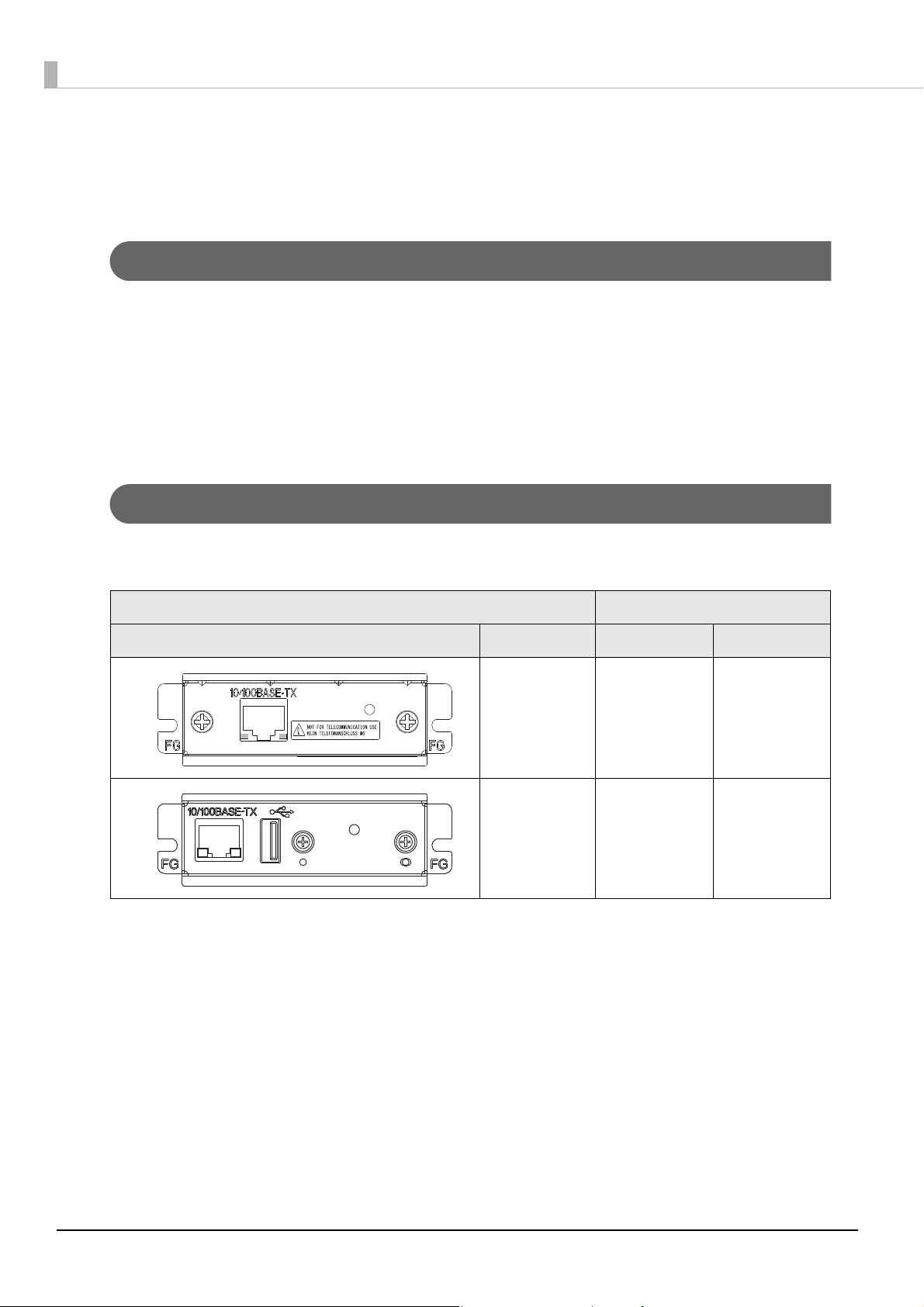
Identification of LAN interface models
TM-L90 has LAN interface models as shown below. To check the technical reference guide for the interface
board specifications and how to set the network, see the technical reference guide shown below.
Interface Board Interface
External View Name Ethernet Wireless LAN
*: For details, see the technical reference guide for the interface board.
UB-E03 ✔ -
UB-E04 ✔✔
*
12
Page 13

Accessories
Included
• Control panel label for vertical installation
• Roll paper spacer*
• AC adapter
•AC cable
• Manuals and documents
*
Not included with some models
*
*
*
Options
• Affixing tape for fixing the printer (Model: DF-10)
• Wall hanging bracket (Model: WH-10)
Chapter 1 Product Overview
1
• Wireless LAN Unit
13
Page 14
Part Names and Functions
1
2
3
4
5
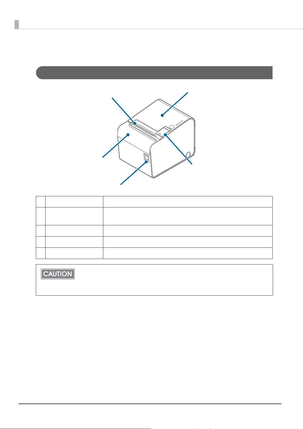
Front
1 Manual cutter Use this cutter when you cut the roll paper manually.
2 Cutter cover If the roll paper cover will not open due a paper jam, open this cover and
unlock the autocutter blade.
3 Power switch Turn on/off the printer.
4 Cover open lever Operate this lever to open the roll paper cover.
5 Roll paper cover Open this cover to install/replace the roll paper.
Before turning the printer off, it is recommended to send a power-off command to the
printer. If you use the power-off sequence, the latest maintenance counter values are
saved. (Maintenance counter values are usually saved every two minutes.)
For information about ESC/POS commands, see the ESC/POS Command Reference.
14
Page 15
Control Panel
1
2
3
4
1
2
3
4
68* model
Chapter 1 Product Overview
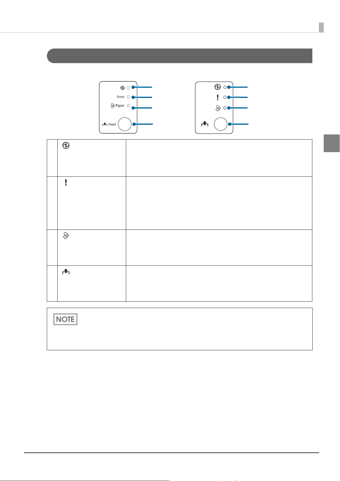
1 LED • On when the power supply is on.
• Off when the power supply is off.
• Flashes during the network startup process after power-on and power-off
standby status, and while updating firmware.
2 (Error) LED • Lights or flashes when the printer is offline.
• Lights after the power is turned on or after a reset (offline). Automatically
goes out after a while to indicate that the printer is ready.
• Lights or flashes when an error occurs. (For information about the indication patterns, see
• Off when the printer is in standard mode (online).
3 (Paper) LED • Lights when there is no more roll paper.
• Flashes to prompt the user to operate the Feed button.
68* model only: Flashes to prompt the user to remove the issued paper
and to operate the Feed button.
4 (Feed) button Press this button to feed the roll paper by one line. Hold down this button to
feed the roll paper continuously.
When using liner-free label paper, and while waiting for the issued paper to
be removed (for 68* model only), the button operation is disabled.
"Status and Errors" on page 18.)
1
• Attach the control panel label for vertical installation when vertical installation is used. The
control panel label for vertical installation is upside down. (
)
24
• The Feed button is also located inside the roll paper cover. (See
page 52
)
"Installing the Printer" on page
"Software Setting Mode" on
15
Page 16
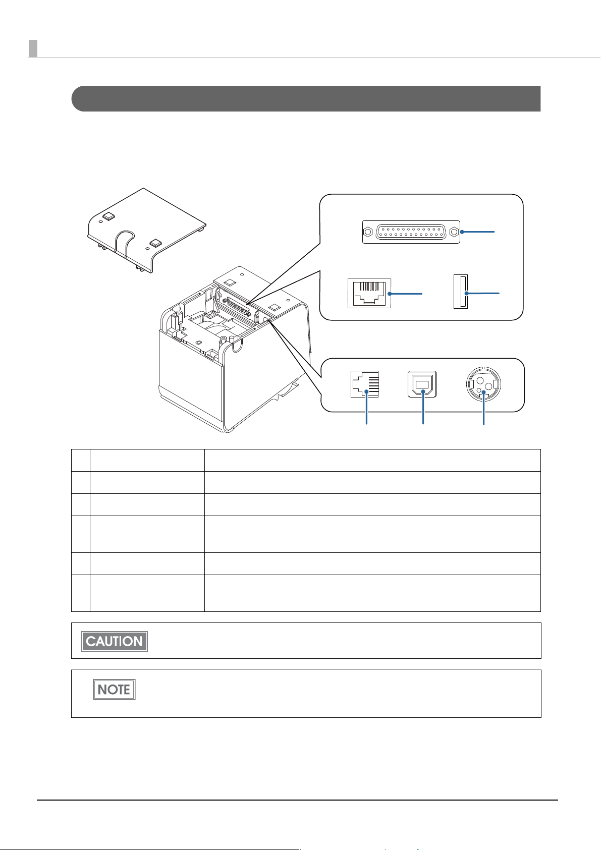
Connectors
1
23
4
5
6
All connectors are located on the bottom of the printer. Different interfaces are used depending on the
printer model to be used.
1 Serial interface Connects the serial cable for connecting to a computer.
2 LAN connector Connects the 10BASE-T/100BASE-TX Ethernet cable.
3 USB connector Used only for connecting optional Wireless LAN unit and customer display.
4 Drawer kick connector Connects the cash drawer or the optional external buzzer.
"Connecting the Cash Drawer" on page 33
5 USB connector Connects the USB cable for connecting to a computer.
6 Power supply connector Connects the AC adapter.
"Connecting the AC Adapter" on page 29
The USB (Type A) interface is used only for connecting the optional Wireless LAN unit.
For details about the connection procedures, see
page 31
page 33
, "Connecting the AC Adapter" on page 29, and "Connecting the Cash Drawer" on
.
"Connecting the Printer to the Host" on
16
Page 17

Chapter 1 Product Overview
Online and Offline
Online
The printer is online and ready for normal printing unless there is a reason to go offline.
Offline
The printer automatically goes offline under the following conditions:
• While the printer power is turning on/off
• While setting/checking mode is being executed (excluding hexadecimal dumping mode)
• While roll paper is fed using the Feed button
• When the printer stops printing due to a paper end (when the paper out detector detects that there is no
paper)
• During an operation standby state
1
• When an error has occurred (
• While the roll paper cover is open
"Status and Errors" on page 18)
17
Page 18
Status and Errors
LED OFF
LED ON
Approx. 320 ms
LED OFF
LED ON
Approx. 320 ms
LED OFF
LED ON
Approx. 320 ms
The LEDs light or flash to indicate the printer status.
The printer cannot print while an error is left unresolved.
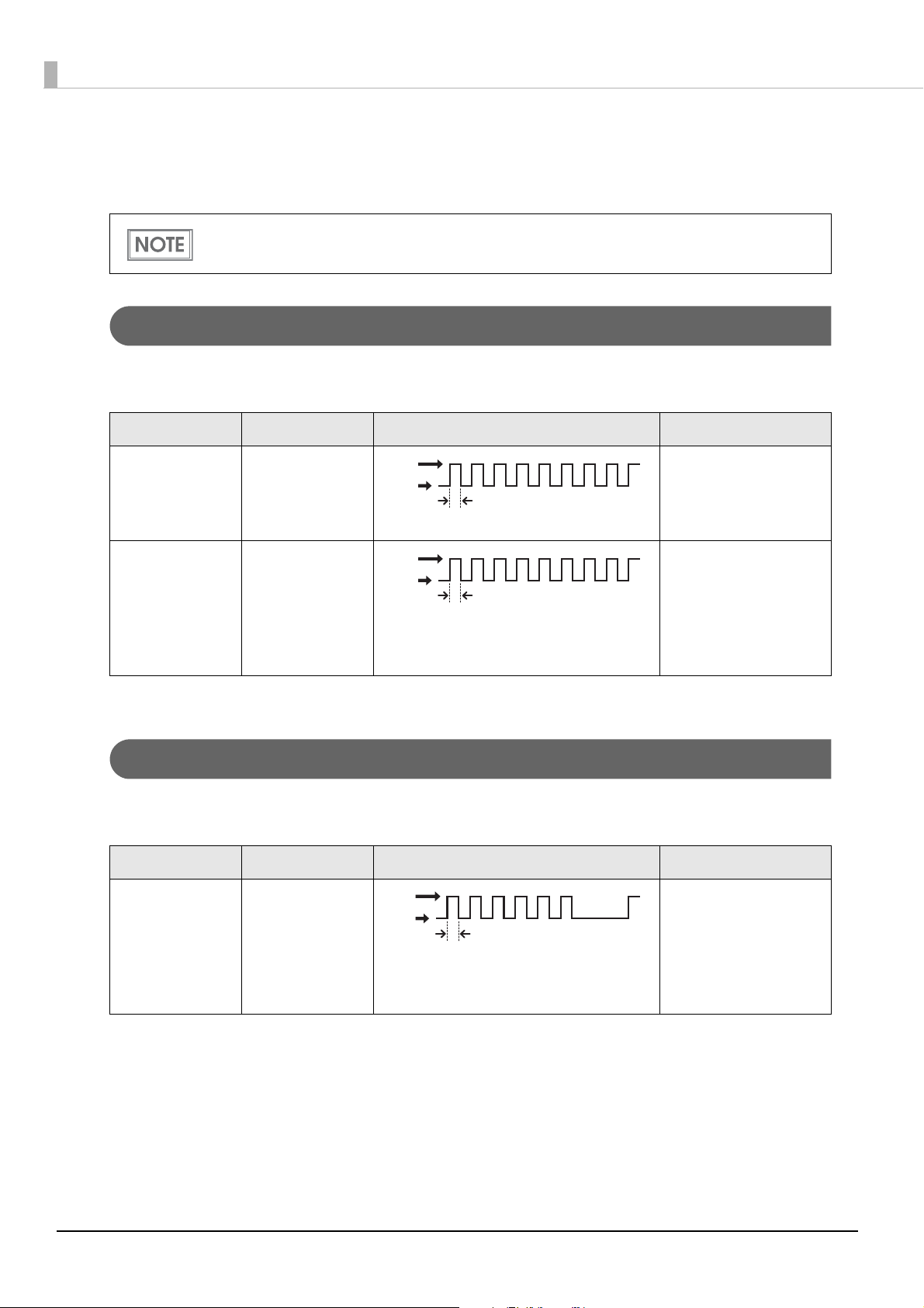
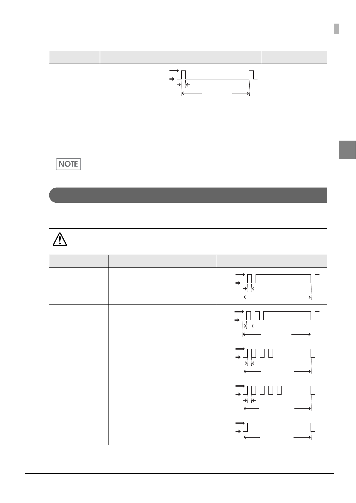
Automatically Recoverable Errors
The printer cannot print when automatically recoverable errors occur. It can be recovered as described
below.
Error Error description Error LED flash code Condition for Recovery
Roll paper cover
open error
*
The roll paper
cover was
opened while
Recovers automatically
when the roll paper
cover is closed.
printing.
Head
temperature
error
A high
temperature
outside the head
Recovers automatically
when the print head
cools.
drive operating
range was
detected.
*
: When the memory switch 8-8 is set to OFF (Roll paper cover open while the printer is printing: automatically recoverable error)
Recoverable Errors
The printer cannot print when a recoverable error occurs. It can be recovered easily by turning the power
on again or sending an error recovery command from the driver after eliminating the cause of the error.
Error Error description Error LED flash code Condition for Recovery
Roll paper cover
open error
*
The roll paper
cover was
opened while
printing.
Recovers when the roll
paper cover is closed
and the error recovery
command is executed
or the power is turned
on again.
18
Page 19
Chapter 1 Product Overview
LED OFF
LED ON
Approx. 320 ms
Approx. 5120 ms
LED OFF
LED ON
Approx. 320 ms
Approx. 5120 ms
LED OFF
LED ON
Approx. 320 ms
Approx. 5120 ms
LED OFF
LED ON
Approx. 320 ms
Approx. 5120 ms
LED OFF
LED ON
Approx. 5120 ms
Error Error description Error LED flash code Condition for Recovery
Autocutter error The Autocutter
does not work
correctly.
LED ON
LED OFF
Approx. 320 ms
Approx. 5120 ms
Recovers when the
jammed paper or
foreign matter is
removed and the roll
paper cover is closed,
and then the error
recovery command is
executed or the power
is turned on again.
*
: When the memory switch 8-8 is set to ON (Roll paper cover open while the printer is printing: recoverable error)
The error recovery command is valid only if a recoverable error (excluding automatically
recoverable errors) occurs.
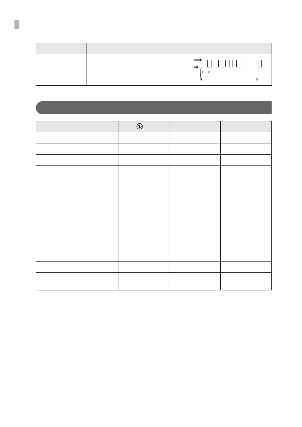
Unrecoverable Errors
1
The printer cannot print when an unrecoverable error occurs. If the error persists after turning the printer
off and then on again, the printer may be defective. Contact qualified service personnel.
Turn off the power immediately when an unrecoverable error occurs.
CAUTION
Error Error description Error LED flash code
R/W error in memory After R/W checking, the printer does not
work correctly.
High voltage error The power supply voltage is extremely
high.
Low voltage error The power supply voltage is extremely
low.
CPU execution error The CPU is executing an incorrect
address.
Internal circuit
connection error
Internal circuits are not connected
correctly.
19
Page 20
Error Error description Error LED flash code
LED OFF
LED ON
Approx. 320 ms
Approx. 5120 ms
Interface error Interface error
Status Display
LED Error LED PaperLED
Online ON OFF OFF
Initializing after power-on ON ON -
Running a self-test ON OFF -
Waiting to continue self-test ON OFF Flashing
Feeding using the Feed button ON OFF -
Waiting to execute a macro ON OFF Flashing
Roll paper cover open while the
ON ON -
printer is not printing
No paper ON ON ON
Near end ON OFF ON
While updating firmware Flashing OFF OFF
In power off standby status Flashing OFF OFF
Waiting to print status sheet ON ON Flashing
68* model only: Paper removal
ON OFF Flashing
standby
-: Changes depending on whether or not paper is detected.
20
Page 21
Chapter 1 Product Overview
NV Memory
The printer is equipped with NV memory (Nonvolatile Memory) to store data even after the printer power is
turned off. NV memory contains the following memory areas for the user:
•NV graphics memory
• User NV memory
• Memory switches
• User-defined page
• Maintenance counter
As a guide, NV memory rewriting should be 10 times or less a day when you program
applications.
NV Graphics Memory
Graphics, such as shop logos to be printed on receipts, can be stored. Even with a serial interface model
whose transmission speed is low, high speed graphic printing is possible.
Use the TMFlogo logo registration utility to register graphics.
User NV Memory
You can store and read text data for multiple purposes, such as for storing a note including customizing or
maintenance information of the printer.
Memory Switches (Customized Value)
You can configure the serial interface communication conditions and other various settings of the printer.
For more information, see
"Software Setting Mode" on page 52.
1
User-defined page
You can store character data in the user-defined page (character code table: page 255) so that you can also
print characters not resident in the printer.
Maintenance Counter
With this function, printer information, such as the number of lines printed, the number of autocuts, and
printer operation time after the printer starts working, is automatically stored in NV memory. You can read
the counter information with the Status API of the APD, OPOS ADK, or ESC/POS commands. You can use the
counter information for periodical checks or part replacement.
21
Page 22

22
Page 23
Chapter 2 Setup
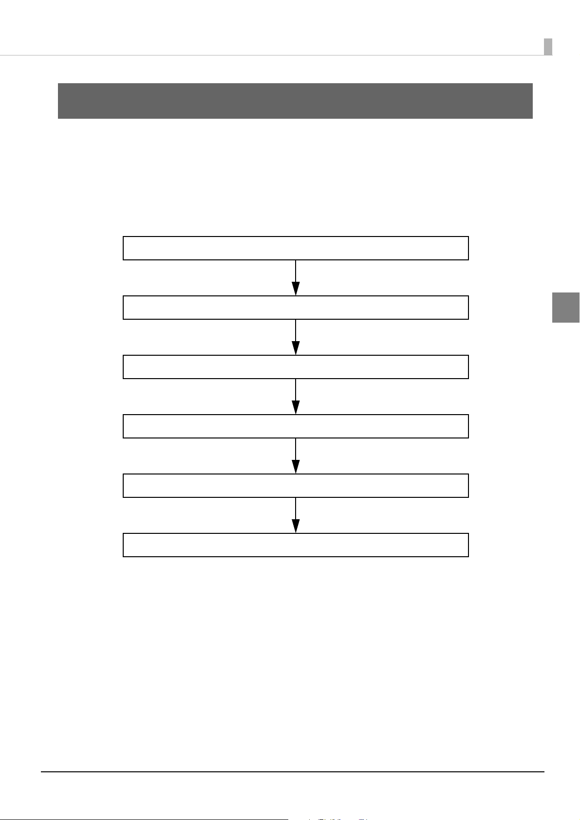
3. Connecting the AC Adapter (29 page)
6. Connecting the Optional Wireless LAN Unit (36 page)
5. Connecting the Cash Drawer (33 page)
4. Connecting the Printer to the Host (31 page)
2. Changing the Paper Width (25 page)
1. Installing the Printer (24 page)
Setup
This chapter describes setup and installation of the product and peripherals.
Flow of Setup
This chapter consists of the following sections along with the setup flow of the product and peripherals.
2
23
Page 24
Installing the Printer
<Vertical installation>
<Horizontal installation>
Control panel for vertical installation
You can install the printer horizontally on a flat surface (with the paper exit on top) or vertically (with the
paper exit at the front). Also, you can hang it on a wall using the optional wall hanging bracket (WH-10).
Attach the control panel label for vertical installation when vertical installation (with the paper exit at the
front) is used.
• Do not place the printer in a dusty location.
• Do not knock or strike the printer. Doing so may cause defective printing.
• Be careful not to catch cables or place foreign matter under the printer during
installation.
24
Page 25
Changing the Paper Width
Install/remove the roll paper guide according to the roll paper width to be used.
The width of the installed roll paper guide differs according to the model by factory default.
❏ 65* model
Equipped with the 40 mm roll paper guide.
• When using 40 mm width roll paper, use this guide.
• When using 80 mm width roll paper, remove the installed guide.
❏ 66*/67*/68* models
Equipped with the 58 mm roll paper guide.
• When using 58 mm width roll paper, use this guide.
• When using 80 mm width roll paper, remove the installed guide.
• When using 40 mm width roll paper, remove the installed guide and install the guide for 40 mm paper supplied with the
product.
Chapter 2 Setup
• Because some parts of the print head and the autocutter blade may contact the platen and
become worn out, you cannot change a smaller paper width to a larger one once you start
using the product.
• The printable area is automatically defined by detecting the installed roll paper guide.
However, to change the paper width from 58 mm to 40 mm, using the memory switch is
required. (
"Memory Switch 6" on page 40)
2
25
Page 26
Removing the Roll Paper Guide
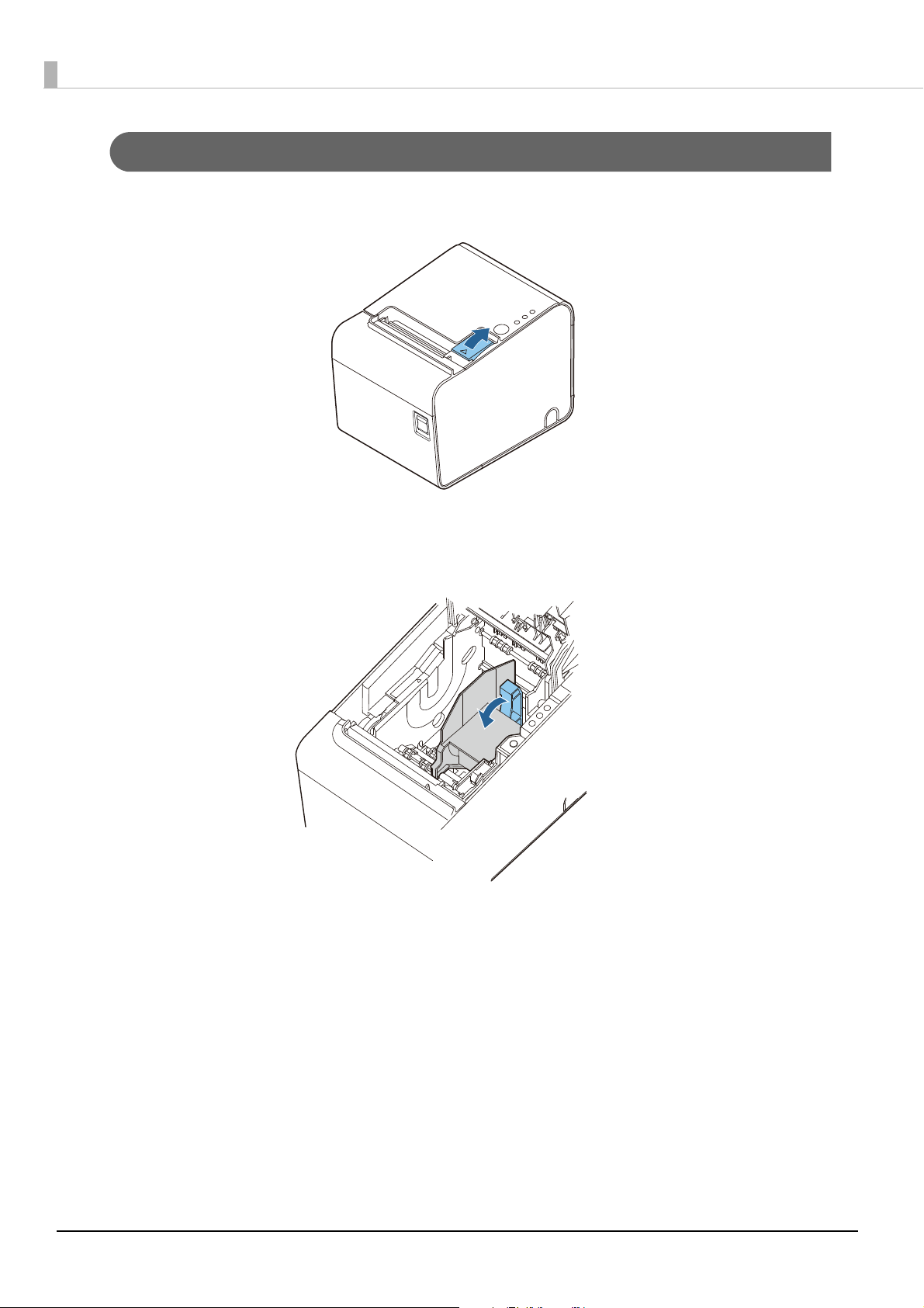
Press the cover open lever to open the roll paper cover.
1
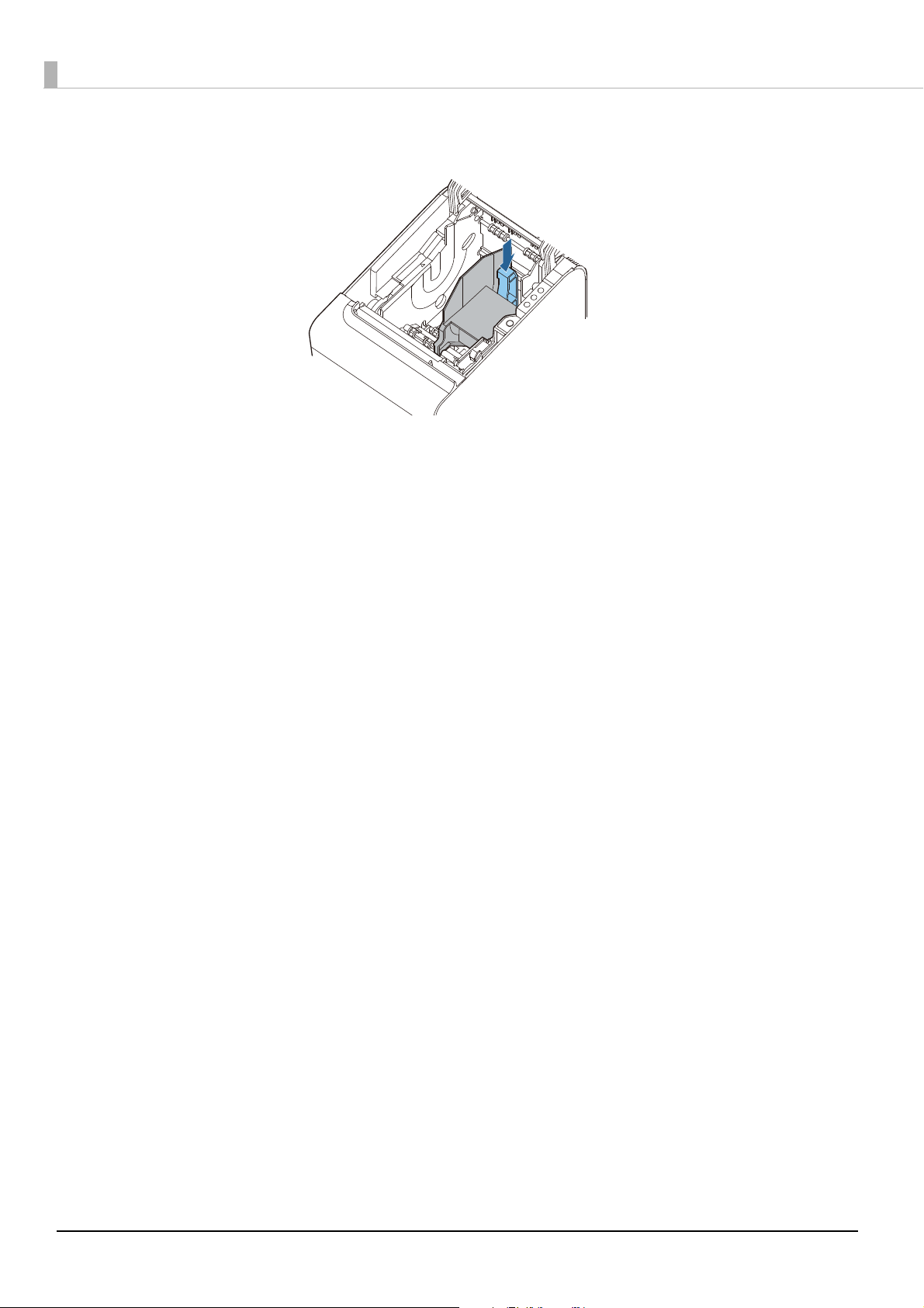
While pushing down the roll paper guide lever in the arrow direction, lift the whole roll paper
2
guide to remove it.
26
Page 27
Chapter 2 Setup
40 mm
58 mm
58 mm
40 mm
Printer Front Side
Hole
Notch
Projection
Installing the Roll Paper Guide
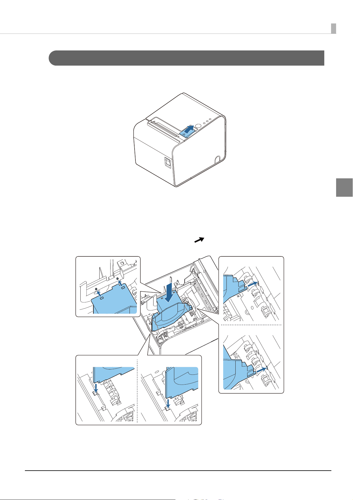
Press the cover open lever to open the roll paper cover.
1
Install the roll paper guide inside the printer.
2
Align the guide with the holes, cutouts, and protrusions in the printer as shown below. The installation position
of the roll paper guide is different depending on the width of the roll paper guide.
2
27
Page 28
Push the lever of the roll paper guide down until the paper guide clicks into place.
3
28
Page 29
Connecting the AC Adapter
For the AC adapter, use PS-180 or the equivalent.
Use the AC cable supplied with the product.
• Use of an unspecified AC adapter may cause fire or electrical shock.
WARNING
AC Adapter Connection Procedure
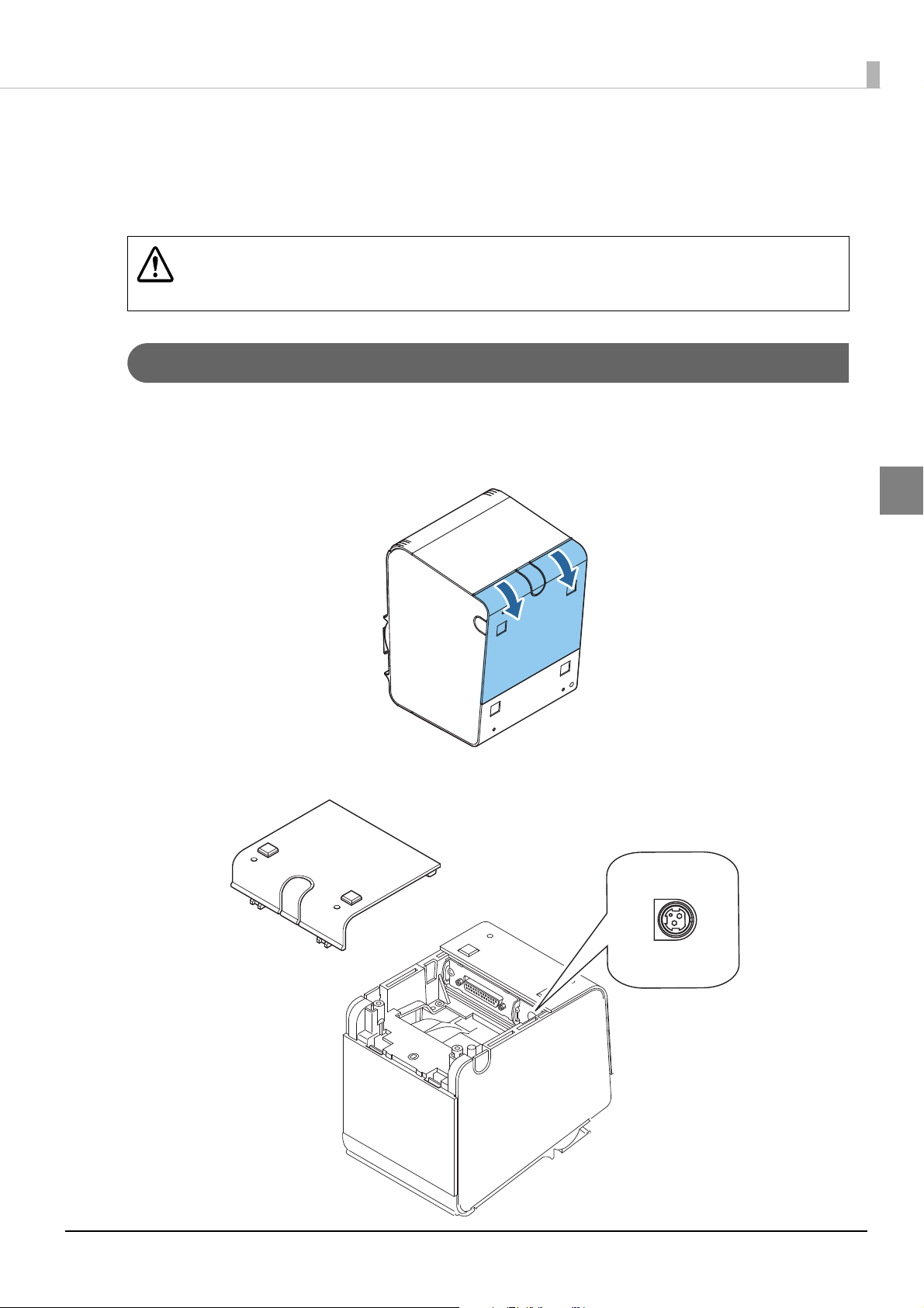
Make sure the printer is turned off.
1
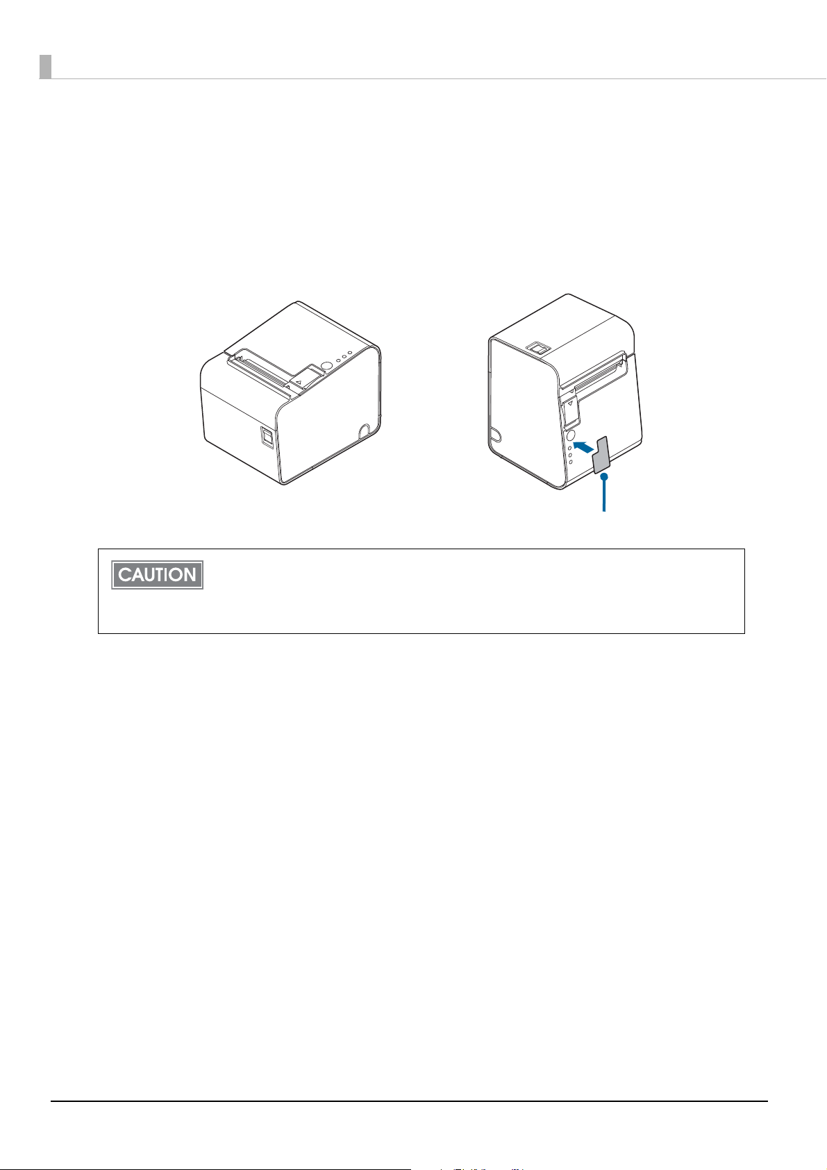
Remove the cover on the rear side of the printer.
2
• Should a fault ever occur, immediately turn off the power to the printer and unplug
the AC cable from the wall socket.
Chapter 2 Setup
2
Connect the DC cable of the AC adapter to the power supply connector (stamped DC 24V).
3
29
Page 30
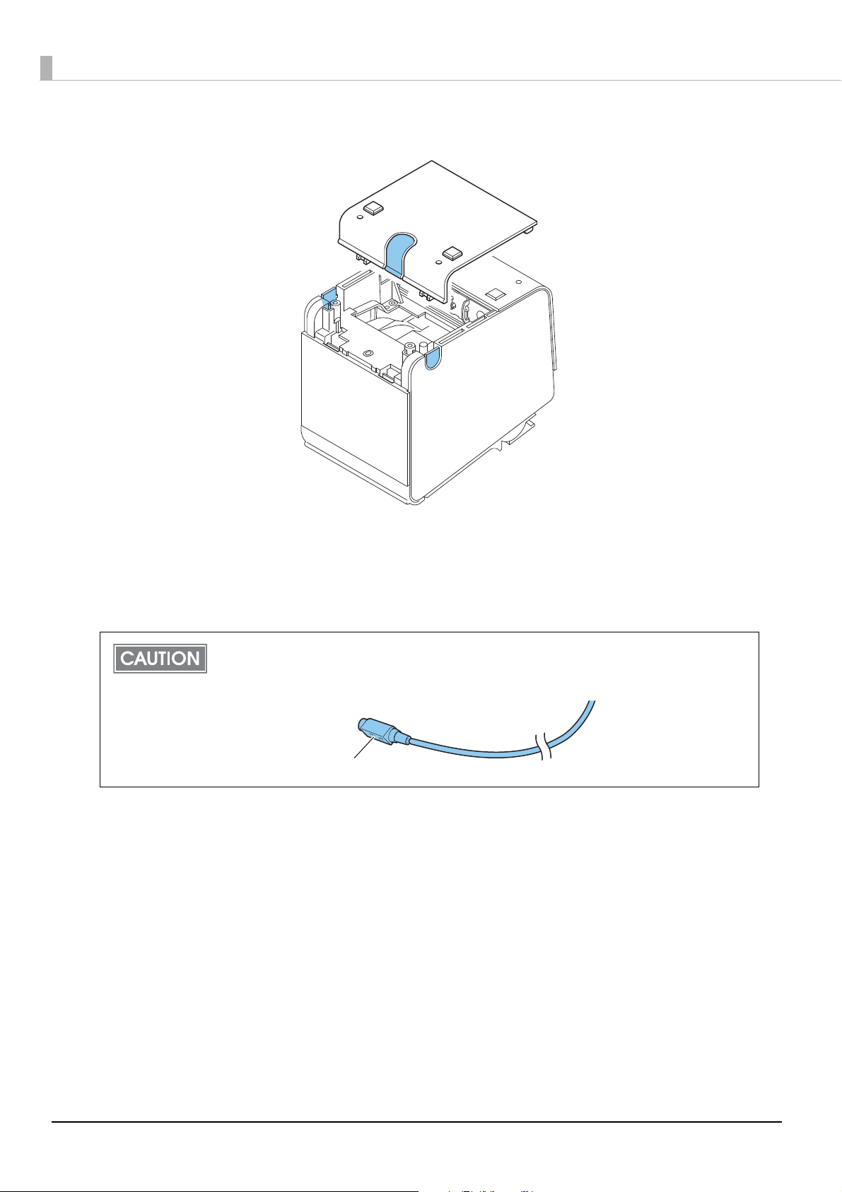
Remove any of the knockouts (at 3 locations) on the rear cover and pass the cable through.
Arrow part of connector
4
Close the rear cover.
5
Connect the AC cable to the AC adapter.
6
Connect the AC cable to the power outlet.
7
Before disconnecting the DC cable of the AC adapter from the printer, make sure that the
AC cable is disconnected. Then, hold the arrow part of the connector and pull out the
cable while keeping it straight.
30
Page 31

Chapter 2 Setup
Locking wire saddle
USB cable
USB connector
Connecting the Printer to the Host
The printer uses a modular connector specifically designed for the cash drawer or for the
customer display. Do not connect these connectors to an ordinary telephone line.
USB Interface
When using USB cable to connect with host device, connect the USB cable to the printer, and after starting
the host device, turn the printer on.
• Do not place any weight or stress on the cable when using. Doing so could damage
the cable and connectors.
• To prevent disconnection of the USB cable, secure the cable to the hook on the
locking wire saddle as shown below.
2
Ethernet Interface
Use an Ethernet cable to connect the printer to a network via a hub.
Use Epson EpsonNet Config to set network. For details about EpsonNet Config, refer to EpsonNet Config
Operations Guide.
• When LAN cables are installed outdoors, make sure they are connected through
devices that have surge protection.
Otherwise, the devices can be damaged by lightning.
• Never attempt to connect the customer display cable, the drawer kick cable, or a
telephone line cable to the LAN connector.
As same with Conventional models, you can use EpsonNet Config (Web version) in the
same way.
User name/password: epson
31
Page 32

For Serial Interface Models
Use Epson's optional cable or the equivalent.
• Crossover cable for RS-232C interface 2 m(model: OI-C01)
D-sub 9-pin (female) connector -D-sub 25-pin (male) connector
When connecting to the host computer through a serial interface (RS-232), connect a serial cable to the
printer, start the host computer, and then turn on the printer.
• When using connectors equipped with screws, tighten the screws on both sides to
secure the connectors firmly.
• When using interface cables equipped with a ground line, attach the ground line to
the screw hole marked “FG” on the printer.
32
Page 33

Chapter 2 Setup
With shielded
Drawer kick connector
Printer side User side (Drawer kick side)
Drawer open/
close switch
Drawer kick
solenoid
1
2
3
4
5
6
Connecting the Cash Drawer
• Two driver transistors cannot be energized simultaneously.
• Leave intervals longer than 4 times the drawer driving pulse when sending it
continuously.
Cash Drawer Requirements
Specifications of drawers greatly differ depending on manufacturers and models. When you use a drawer
other than specified, make sure its specification meets the following conditions.
Otherwise, devices may be damaged.
• The load, such as a drawer kick solenoid, must be connected between pins 4 and 2 or pins 4 and 5 of the
drawer kick connector.
• When the drawer open/close signal is used, a switch must be provided between drawer kick connector
pins 3 and 6.
2
• The resistance of the load, such as a drawer kick solenoid, must be 24 ohms or more or the input current
must be 1 A or less.
• Be sure to use the 24 V power output on drawer kick connector pin 4 for driving the equipment.
Drawer Connection Diagram
F.G
+24V
Connector
Modular connector RJ12
33
Page 34

Pin assignments
6 5 4 3 2 1
Pin
number
1Frame GND -
2Drawer kick drive signal 1Output
3 Drawer kick open/close signal Input
4+24 V -
5Drawer kick drive signal 2Output
6Signal GND -
Signal name Direction
34
Page 35

Chapter 2 Setup
DK
24V
Connecting the Drawer Kick Cable
• Use a shield cable for the drawer kick cable.
WARNING
Connect the drawer kick cable to the drawer kick connector by pressing firmly until the connector clicks
into place.
• When using cash drawer, make sure to use the power supply for printer (connector
pins 4).
• Do not insert a telephone line into the drawer kick connector.
• Doing so may damage the telephone line or printer.
2
35
Page 36

Connecting the Optional Wireless LAN Unit
The optional Wireless LAN cable set enables you to use the product with a Wi-Fi connection. For more
information, refer to User’s Manual of the Wireless LAN cable set.
• Be sure to turn off the printer when connecting the Wireless LAN unit.
• Depending on the installation conditions of the printer and the routing for cables
connected to it, the status of the radio waves for the Wireless LAN unit may decline. If
this does happen, use an extension cable.
36
Page 37

Chapter 3 Advanced Usage
Advanced Usage
Software Settings
With the functions such as the memory switches and customized values, which are software settings for
this printer, you can set the various functions.
For an outline of the functions, see the following pages. Use the software setting mode or the memory
switch setting utility for setting the functions.
• In the software setting mode, panel operations on the printer are used to configure
settings. For details about the panel operations, see
• For information about how to use the memory switch setting utility, see the User's Manual
for the memory switch setting utility.
• For information about ESC/POS commands, see the ESC/POS Command Reference.
• To check the setting status, use the self-test (
switch setting utility.
"Self-test Mode" on page 50) or the memory
"Software Setting Mode" on page 52.
Item/Method
Transmission of the power ON information
Capacity of receive buffer
1
Condition for BUSY
Data receive error
Automatic line feed
2 Autocutter operation
Autocutting position
Auto scaling for 40/58 mm width paper
Memory Switches
Auto top margin scaling
6
Selection of the characters per line for 80 mm
width paper
Selection of paper width
Enable left or right margin of bar code print
8
Roll paper cover open during operation
Software Setting
Mode
✔✔
✔✔
✔✔
✔✔
✔✔
✔✔
✔✔
✔✔
✔✔
✔✔
Memory Switch
Setting Utility
3
✔
37
Page 38

Item/Method
Software Setting
Mode
Memory Switch
Setting Utility
User NV memory capacity setting
NV graphics memory capacity setting
Selection of the energization parting
Selection of printing density
Selection of print speed
Automatic Paper Reduction
Auto image data scaling
Customized value
Selection of the media type detection method*
Amount of top margin by backfeed*
Stop position when Label cutting*
Selection of paper removal standby*
Serial interface communication condition setting
∗ *: 68* model only
✔
✔
✔
✔✔
✔✔
✔✔
✔✔
✔✔
✔✔
✔✔
✔✔
✔✔
38
Page 39

Chapter 3 Advanced Usage
Memory Switch 1
SW Function ON OFF
1-1 Transmission of the power ON information Transmits Does not transmit
1-2 Capacity of receive buffer 45 bytes 4 KB
1-3 Condition for BUSY Receive buffer full
1-4 Data receive error Ignored Prints "?"
1-5 Automatic line feed Enabled Disabled
1-6 to 1-8 Reserved — —
• Regardless of the settings for memory switches 1-3, the printer enters the BUSY state
after the power is turned on (including the reset using the interface), and when a selftest is being run.
• If the memory switches 1-3 are set to ON, the printer will not become BUSY in the
following cases:
* When the roll paper cover is open
* When paper is fed by the FEED button
* When printing has stopped due to paper out
* When macro execution ready state
* When error has occurred
Receive buffer full or
Offline
Memory Switch 2
3
SW Function ON OFF
2-1 Reserved (Do not change the setting) Fixed to On
2-2 Autocutter operation Enabled Disabled
2-3 to
2-8
Reserved — —
39
Page 40

Memory Switch 6
SW Func tion ON OFF
6-1 Autocutting position
6-2 Auto scaling for 40/58 mm width paper
6-3 Auto top margin scaling
6-4
6-5
6-6 to
6-7
Selection of the characters per line for 80 mm
width paper
Reserved — —
6-8 Paper width selection
*1: For details about the characters per line and character specifications with this function enabled, see "Details of Characters Per Line and
Character Specifications with Auto Scaling Enabled" on page 78.
*2: Enabled when printing continues after autocutting.
To set the function using the software setting mode, select [11. Top margin reduction] - [11.2 when Paper removal standby is invalid].
*3: With the 67*/68*(multilingual) models, the functions for the memory switches 6-3/6-4/6-5 are reserved and unavailable.
*4: With the 65* model, the function for memory switch 6-8 is reserved and unavailable.
*2
*3
*4
*1
Cut at black mark
position
Enabled Disabled
Enabled Disabled
See the table below.
"Selection of the characters per line for 80 mm width paper
(compatible mode)" on page 40
58 mm/80 mm 40 mm/80 mm
Cut regardless of black
mark position
Selection of the characters per line for 80 mm width paper (compatible mode)
Compatible mode
TM-T88
compatible mode (1)
TM-T88
compatible mode (2)
TM-L90
compatible mode
Characters per line
Memory Switch 6
The printing and autocutting positions change depending on the software setting. For details,
see
Font A 42 44 48
Font B 55 57 64
6-4 ON ON OFF
6-5 ON OFF OFF
"Printing and Cutting Positions" on page 92.
40
Page 41

Chapter 3 Advanced Usage
Memory Switch 8
SW Func tion ON OFF
8-1 to
8-4
8-5 Enable left or right margin of bar code print Enables margin
8-6 Reserved — —
8-7 Reserved — —
8-8
Roll paper cover open while the printer is
Reserved — —
Does not enable
margin
Automatically
recoverable errors
printing
Recoverable errors
3
41
Page 42

Customized value
User NV memory capacity setting
•1 KB (default setting)
•64 KB
•128 KB
•192 KB
NV graphics memory capacity setting
The memory area for NV graphics data and the user NV memory area use a common area. Therefore, the
memory capacity that can be set for NV graphics changes depending on the user NV memory capacity
setting. If the specified memory capacity for NV graphics is out of the allowable range, the capacity is
automatically changed to a value that can be set.
Capacity of the user NV
memory
1 KB
64 KB
128 KB
192 KB • None
Capacity of the NVgraphics
•None
•64 KB
•128 KB
•192 KB
•256 KB
•320 KB
• 384 KB (default setting)
•None
•64 KB
•128 KB
•192 KB
•256 KB
•None
•64 KB
•128 KB
42
Page 43

Selection of the energization parting
• One-part energizing (default setting)
•Two-part energizing
• Three-part energizing
•Four-part energizing
· In normal operation, there is no need to change the energization parting.
· The maximum print speed is available only in the one-part energizing mode.
· Four-part energizing mode can reduce power consumption.
Selection of printing density
Models Media type Density setting Default setting
Chapter 3 Advanced Usage
Other than the 68*
model
68* model Thermal paper 100 - 130%
Depending on the paper type, it is recommended to set the print density as shown in the table below for
the best print quality.
Thermal paper (without black marks):
Original Paper type Density
P35524, P30523, P31523 120%
TF50KS-EY, F5041(55), KT55FA, KT48FA 115%
AF50KS-E 110%
KF50 100%
Thermal paper 100 - 130%
(in increments of 5%)
Liner-free label paper Fixed Fixed
(in increments of 5%)
Liner-free label paper 75 - 100% (in increments of 5%) 100%
120%
120%
3
Liner-free label paper (with black marks):
Density
Original Paper type
9023–1274, 9023–1253 (Lane coated: 80 mm) Fixed 100%
9023–1823, 9023–1397 (Lane coated: 58 mm) Fixed 100%
9023–1275, 9023–1257 (Lane coated: 40 mm) Fixed 100%
When the print density level is increased, print speed may be reduced.
Other than the
68* model
Density
68* model
43
Page 44

Selection of print speed
Selectable from levels 1 to 11 (Slow – Fast)
Default setting: level 11
• Printing speed may be slower, depending on items such as the print data, head
temperature, and energization parting.
• If white lines are caused by intermittent printing (printing sometimes stops) in graphics
printing, etc., set the print speed at low speed or, for serial interface models, set the
communication speed at high speed to prevent white lines.
Automatic Paper Reduction
Reduction of top margin
•Does not reduce
• Reduces
Reduction of bottom margin
•Does not reduce
• Reduces
Reduction of line spacing
•Does not reduce
• Reduces 25%
• Reduces 50%
• Reduces 75%
• Reduces the most (68* model only)
Reduction of line spacing where extra line feeds are included
•Does not reduce
• Reduces 25%
• Reduces 50%
• Reduces 75%
Reduction of bar code heights
•Does not reduce
• Reduces 25%
• Reduces 50%
• Reduces 75%
44
Page 45

Chapter 3 Advanced Usage
Reduction ratio of character height (68* model (ANK) only)
•Does not reduce
• Reduces 25%
• Reduces 50%
• Reduces 75%
• Reduces 75% and shortens character height
• Reduces the most and shortens character height
• The printing and autocutting positions change depending on the paper type or the
software setting. (
• Some selections are unavailable in the self-test mode. Use the memory switch setting
utility.
"Printing and Cutting Positions With Software Setting" on page 96)
Auto image data scaling
• Nearest neighbor interpolation: Shrink the image data by 82%, keeping the aspect ratio.
• Cut off both sides: Cut off 46 dots from the edge of both sides of the image data.
• Cut off the right side: Cut off 92 dots from the right side of the image data.
• Cut off the left side: Cut off 92 dots from the left side of the image data.
• None: Actual size image data is defined or printed
• This function has the following restrictions:
* The print-start time will be late.
* The print-result may have a blank line.
• This function is not available, if the data is less than 92 dots.
Selection of the media type detection method
• Auto detection (default setting)
• Fixed to liner-free label paper
• Fixed to continuous paper without black marks
Amount of top margin by backfeed
This function is enabled when the selection of paper removal standby is set to "Enabled".
3
Selectable from 4.0 to 14.0 mm (in increments of 0.5 mm)
Default setting: 4 mm
• The printing and autocutting positions change depending on the paper type or the
software setting. (
• To set the function using the software setting mode, select [11. Top margin reduction] -
[11.1 when Paper removal standby is invalid].
"Printing and Cutting Positions With Software Setting" on page 96)
45
Page 46

Stop position when Label cutting
• Arbitrary stop position (default setting)
• Specific stop position
The printing and autocutting positions change depending on the paper type or the software
setting. ("Printing and Cutting Positions With Software Setting" on page 96
Selection of paper removal standby
• Enabled (default setting)
•Disabled
)
46
Page 47

Communication condition of serial interface
Transmission speed
• 2400 bps
• 4800 bps
• 9600 bps
• 19200 bps (default setting)
• 38400 bps
• 57600 bps
• 115200 bps
[bps: bits per second]
Parity
Chapter 3 Advanced Usage
• No parity (default setting)
•Odd parity
•Even parity
Handshaking
• DSR/DTR (default setting)
•XON/XOFF
Bit length
•7 bits
• 8 bits (default setting)
3
47
Page 48

Setting/Checking Modes
Close the roll paper cover, and turn on the printer while pressing the Feed button.
Self-test
Close the roll paper cover, and turn on the printer while pressing the Feed button.
Release the Feed button when the Error LED turns on
+
Press the Feed button two times briefly
+
The roll paper cover is closed
Software setting
Release the Feed button when the LED turns on
+
The roll paper cover is closed
Hexadecimal dumping
1
Briefly press the Feed button
Continuing the self-test
Hold down the Feed button
Mode selection guidance
2
Press the Feed button once briefly and
then hold it down
NV graphics information print
Press the Feed button two times briefly
and then hold it down
Software setting
As well as print mode, the following modes are also provided for making various printer settings and
checking items.
• Self-test mode
• NV graphics information print mode
• Software setting mode
• Hexadecimal dumping mode
You can select the mode depending on the operation at power-on.
In (1) and (2), the following guidances are printed, the Paper LED flashes, and instructs the user's operations.
48
Page 49

1. Continuing self-test guidance
2. Mode selection guidance
Chapter 3 Advanced Usage
Mode Selection
Modes
0: Exit and Reboot Printer
1: NV Graphics Information
2: Customize Value Settings
3: or more: None
Select Modes by executing following
procedure.
step 1. Press the Feed button less
than 1 second as many times
as the selected mode number.
step 2. Press Feed button for 1
second or more.
3
49
Page 50

Self-test Mode
In the self-test mode, the printer prints the current printer status and a rolling pattern test print of resident
characters.
The current status print includes the following information:
•Control software version
• Serial number
• Interface type
• Receive buffer size
• BUSY condition
• Built-in fonts
• Auto line feed enabled/disabled
•Print density
• Power ON status transmission enabled/disabled
• Paper width to be set
• Media type detection
• Type of paper
• Stop position when Label cutting
• Setting status of paper removal standby
•Various sensor values
• Print speed to be set
• Top margin length
• Maintenance information
• Memory switch settings
Follow the procedures below.
Close the roll paper cover.
1
While pressing the Feed button on the control panel, turn on the printer. (Hold down the Feed
2
button until printing starts.)
After printing the current print status, a Continuing self-test guidance is printed, and the Power LED flashes.
Briefly press the Feed button (less than one second) to continue the self-test.
3
The printer prints a rolling pattern on the roll paper, using the built-in character set.
After “*** completed ***” is printed, the printer initializes and switches to standard mode.
50
Page 51

Chapter 3 Advanced Usage
NV Graphics Information Print Mode
Prints the following NV graphics information registered to the printer.
• Capacity of the NV graphics
• Used capacity of the NV graphics
• Unused capacity of the NV graphics
• Number of NV graphics that are registered
• Key code, number of dots in X direction, number of dots in Y direction to be defined.
• NV graphics data
For details on NV graphics, see "NV Graphics Memory" on page 21.
Follow the procedures below.
After running a self-test, hold down the Feed button for at least one second to enter the Mode
1
selection.
The Mode selection guidance is printed, and the Paper LED flashes.
After briefly (less than one second) pressing the Feed button once, hold it down for at least one
2
second, to print the NV graphics information.
After information printing, the Mode selection guidance is printed again.
To finish, turn off the power, or select “Exit and Reboot Printer”.
3
3
51
Page 52

Software Setting Mode
Feed button
This mode is used to set the memory switches and the customized values of the printer.
• For information about the memory switches, see "Software Settings" on page 37.
• The software setting mode can also be started from the self-test mode. (
on page 37
Follow the procedures below.
Make sure that the roll paper is properly installed and that the printer is turned off.
1
Open the roll paper cover.
2
While pressing the Feed button in the printer, turn on the printer.
3
Hold down the Feed button until the Error LED turns on.
)
"Advanced Usage"
Release the Feed button when the Error LED turns on.
4
52
Page 53

Press the Feed button two times and close the roll paper cover.
5
The operation guidance is printed.
Chapter 3 Advanced Usage
Press the Feed button in the printer the number of times indicated on the print result, and close
6
the roll paper cover.
When one setting has been completed, the printer stores the setting.
For details on setting items, see
To exit the software setting mode, turn off the printer.
7
• To select 0 as the item number, hold down the Feed button until printing starts.
• If the button is pressed a number of times that is not displayed by the Setup guidance, the
operation is invalid and the same guidance is printed.
"Software Settings" on page 37.
3
53
Page 54

Starting Hexadecimal Dumping Mode
Feed button
Hexadecimal Dump
To terminate hexadecimal dump,
press FEED button three times.
1B 21 00 1B 26 02 40 40 1B 69 .!..&.@@.i
1B 25 01 1B 63 34 00 1B 30 31 .%..c4..01
41 42 43 44 45 46 47 48 49 4A ABCDEFGHIJ
. ! . . & . @ @ . i
. % . . c 4 . . 0 1
ABCDEFGHIJ
In the hexadecimal dumping mode, the printer prints the data transmitted from a host device in
hexadecimal numbers and their corresponding characters. It enables you to check if data is transmitted to
the printer correctly.
• If there is no character corresponding to print data, “.” is printed.
• If you press the Feed button when there is less than one line of print data, one line is
printed.
• During hexadecimal dumping mode, applications that check the printer status may
not operate correctly. The printer only returns the status for the “Real-time
transmission status” command.
Follow the procedures below.
Open the roll paper cover.
1
While pressing the Feed button in the printer, turn on the printer.
2
Close the roll paper cover.
3
The printer starts printing data received from then on in hexadecimal numbers and their corresponding ASCII
characters.
Example of printing in hexadecimal dumping mode
54
*** completed ***
Page 55

Chapter 3 Advanced Usage
To close hexadecimal dumping mode, turn off the printer after printing is complete, or press the
4
Feed button for three times.
3
55
Page 56

56
Page 57

Chapter 4 Application Development
Application Development Information
This chapter describes how to control the printer and gives information useful for printer application
development.
Controlling the Printer
The printer supports the following command system:
•ESC/POS
Users can control the printer by using the aforementioned command, or the following development kits or
drivers.
• EPSON Advanced Printer Driver (APD)
• OPOS ADK
• OPOS ADK for .NET
• JavaPOS ADK
•Epson ePOS SDK for Android
• Epson ePOS SDK for iOS (models equipped with UB-E04 only)
ESC/POS
ESC/POS is the Epson original printer command system for POS printers and customer display.
With ESC/POS commands, you can directly control all the printer functions, but detailed knowledge of
printer specifications or combination of commands is required, compared to using drivers and applications.
For details of ESC/POS, see the ESC/POS Command Reference. The ESC/POS Command Reference can be
accessed at the following URL.
www.epson-biz.com/pos/reference/
4
57
Page 58

Controlling the Cash Drawer
A pulse output is sent to drawer kick connector pin 2 or pin 5, and you can open the drawer.
You can also check the open/close status of the drawer by checking the signal level of the drawer kick
connector pin 3.
These controls are executed by a driver or by commands.
ESC/POS Commands
The output command for the specified pulse and the status transmission command are provided.
For details, see the ESC/POS Command Reference.
For Windows Printer Drivers (APD)
You can set so that the drawer opens at the start/end of printing or start/end of a page. For details, see the
manual for drivers.
For details on control, see the manual for Status API of the driver.
OPOS (OCX Driver)
Register a cash drawer using the SetupPOS Utility, and control using the OpenDrawer method or the
DirectIO function.
For details, see the “EPSON OPOS ADK MANUAL APPLICATION DEVELOPMENT GUIDE Cash Drawer” and the
“UnifiedPOS Specification”.
OPOS for .NET
Register a cash drawer using the SetupPOS Utility, and control using the OpenDrawer method or the
DirectIO function.
For details, see the “EPSON OPOS ADK for .NET MANUAL Application Development Guide Cash Drawer
(EPSON Standard)” and the “UnifiedPOS Specification”.
Epson ePOS SDK
The output command for the drawer kick pulse and the status transmission command are provided in the
SDK library. For details, see the user's manuals provided with the SDK.
• Which drawer kick connector, pin 2 or pin 5, is used for operation depends on the
connected cash drawer.
• You can acquire documents regarding the UnifiedPOS from the following link.
https://www.omg.org/retail/unified-pos.htm
58
Page 59

Chapter 4 Application Development
Software
The following software is provided for application development.
Development Kits
Software Description
EPSON OPOS ADK This OCX driver can control POS peripherals using OLE technology *1.
Because controlling POS peripherals with original commands is not
required on the application side, efficient system development is possible.
EPSON OPOS ADK for .NET The OPOS ADK for .NET is a POS industry standard printer driver
compatible with Microsoft POS for .NET.
It allows you to develop applications that are compatible with the UPOS
(Unified POS) specification.
When developing applications, use a separate development environment
such as Microsoft Visual Studio .NET.
EPSON JavaPOS ADK
(Windows/Linux)
Epson ePOS SDK This is a development kit for controlling TM printers from native
for Android
for iOS
*1: OLE technology developed by Microsoft divides software into part blocks. The OPOS driver is presupposed to be used with a
development environment, such as Visual Basic, unlike ordinary Windows printer drivers. It is not a driver to be used for printing from
commercial applications.
You can acquire documents regarding the UnifiedPOS from the following link.
https://www.omg.org/retail/unified-pos.htm
JavaPOS is the standard specification which defines an architecture and
device interface (API) to access various POS devices from a Java based
system. Using JavaPOS standard API allows control with Java based
applications of functions inherent to each device. A flexible design with
Java language and JavaPOS enables many different types of computer
systems, such as stand alone or network configuration, to use a same
application. You can use JavaPOS to build applications and drivers
independently of platforms. This allows flexible configurations using thin
clients to meet the system requirements.
applications of smart devices. This includes libraries, manuals, and sample
programs.
4
59
Page 60

Drivers
Software Description
EPSON Advanced Printer Driver
(APD)
EPSON TM Virtual Port Driver This is a serial/parallel-USB/LAN conversion driver to
In addition to ordinary Windows printer driver functions,
this driver has controls specific to POS. The Status API
(Epson original DLL) that monitors printer status and
sends ESC/POS commands is also attached to this driver.
make an Epson TM/BA/EU printer connected via USB or
LAN accessible from a POS application through a virtual
serial or parallel port.
It allows you to directly control devices connected via
USB or LAN with ESC/POS commands without making
changes in the POS application that controls devices
connected via a serial or parallel interface.
Utilities
Software Description
Operating
environment
Windows
Windows
Operating
environment
TMFlogo Logo Setup Utility Used to register logos (for example, shop logos) to the
NV memory of the printer.
MSWUTL Memory Switch
Setting Utility
EpsonNet Config A network setting tool for Epson network products. Windows
Epson Deployment Tool Use to make network and printer settings
Epson Monitoring Tool Use to check a list of status for the Epson printers
EPSON TMUSB Identifier Utility A tool used to change the USB identification code (USB
Used to change the settings for the memory switches
and customized values of the printer.
simultaneously. Allows you to make settings efficiently at
the time of introducing TM printers for the first time, or
when configuring multiple TM printers at the same time.
connected to the network.
You can also update certificates for multiple printers
used for WPA2-Enterprise in a batch.
Serial No.). Using this tool makes replacement due to a
failure easier.
Windows
Windows
Mac
Windows
Windows
Windows
60
Page 61

Chapter 4 Application Development
Download
You can obtain software and manuals from one of the following URLs.
For customers in North America, go to the following web site:
www.epson.com/support/
For customers in other countries and regions, go to the following web site:
www.epson-biz.com/?service=pos
4
61
Page 62

62
Page 63

Handling
This chapter describes basic handling of the printer.
Installing and Replacing Roll Paper
• Do not open the roll paper cover while printing or autocutting.
CAUTION
The printer may be damaged.
• Do not touch the manual cutter with your hands when installing or replacing the
roll paper.
Doing so may injure your hand or finger.
• Use roll paper that meets the printer specification. For details about paper
specification, see
• Do not use a roll paper whose end is pasted to the paper core.
"Paper Specifications" on page 85.
Chapter 5 Handling
Press the cover open lever to open the roll paper cover.
1
Remove the used roll paper core, if any.
2
5
63
Page 64

Install the roll paper in the correct direction.
Horizontal installation Vertical/wall-hanging installation
Vertical/wall-hanging installation
Horizontal installation
3
Pull out some roll paper along the guide, and close the roll paper cover.
4
Close the roll paper cover firmly by pressing the center of the cover.
Cut the roll paper with the manual cutter.
5
When the printer power is on, the roll paper is automatically cut.
64
Page 65

Removing Jammed Paper
Do not touch the thermal head. (See "Cleaning the Printer" on page 69.)
CAUTION
Turn off the printer.
1
Press the cover open lever to open the roll paper cover.
2
After printing, the thermal head and its surroundings can be very hot.
Chapter 5 Handling
Remove the jammed paper.
3
Reinstall the roll paper and close the roll paper cover.
4
5
65
Page 66

If the printer is used for a long time, the platen roller may become worn out, allowing the linerfree label paper to stick to the platen roller easily. If you leave the liner-free label paper in the
printer for a long time, the liner-free label paper may stick to the platen roller, which may
cause paper jams.
If a paper jam occurs, clean the inside of the printer. ("Cleaning the Inside of the Printer" on
page 69
If paper jams occur frequently even after cleaning, replace the platen roller. Contact qualified
service personnel.
)
It may be possible to prevent paper jams in advance by reinstalling the roll paper. (
and Replacing Roll Paper" on page 63
If you leave the 68* model printer turned on for a long time (approx. 12 hours) without
printing, periodic paper feed is operated automatically in order to prevent the liner-free label
paper from sticking to the platen roller. During the next print after the paper feed operation,
the top margin is increased even when back feed is enabled. When back feed is disabled,
printing errors may occur.
)
"Installing
66
Page 67

Chapter 5 Handling
Releasing a Stuck Roll Paper Cover
If you cannot open the roll paper cover, a jammed auto cutter blade may be blocking it.
Try turning the printer off and on to return the blade to its home position. If you still cannot open the cover,
follow the steps below.
Turn the printer off.
1
Insert a spudger or a small flat-head screwdriver into the slot on either side of the auto cutter
2
cover.
Note: The printer shown may differ from your product, but the steps are the same.
Tilt the tool upwards until it is vertical. This will cause a slight separation between the side of the
3
printer and the auto cutter cover.
5
67
Page 68

Remove the auto cutter cover.
4
Use the tool or your finger to turn the auto cutter knob in the direction indicated by the arrow.
5
Once the triangle is visible in the opening, the blade is in its home position and you will be able
to open the roll paper cover.
Triangle
Knob
Note: You may need to rotate the knob several times. To reduce the possibility of future auto cutter jams, use
tweezers to remove any visible paper debris from the auto cutter.
Reattach the auto cutter cover.
6
68
Page 69

Chapter 5 Handling
Thermal head
Cleaning the Printer
Cleaning the Printer Case
Be sure to turn off the printer, and wipe the dirt off the printer case with a dry cloth or a damp cloth. Be sure
to unplug the AC cable while cleaning.
Never clean the product with alcohol, benzine, thinner, trichloroethylene, or ketone-
CAUTION
Cleaning the Inside of the Printer
Epson recommends cleaning the inside of the printer periodically (generally every 6 months) to maintain
print quality. Paper dust or glue from the label paper accumulated in the printer may cause an irregular
paper feed, improper cutting, or paper jams.
Turn on the printer power only after the cleaned area has completely dried.
based solvents.
Doing so may damage or break the parts made of plastic and rubber.
Thermal head and its surroundings
Turn off the printer and open the roll paper cover. Clean the thermal elements of the thermal head and its
surroundings with a cotton swab moistened with an alcohol solvent (ethanol or IPA).
• After printing, the thermal head can be very hot.
CAUTION
Let it cool before you clean it.
• Do not damage the thermal head by touching it with your fingers or any hard
object.
5
69
Page 70
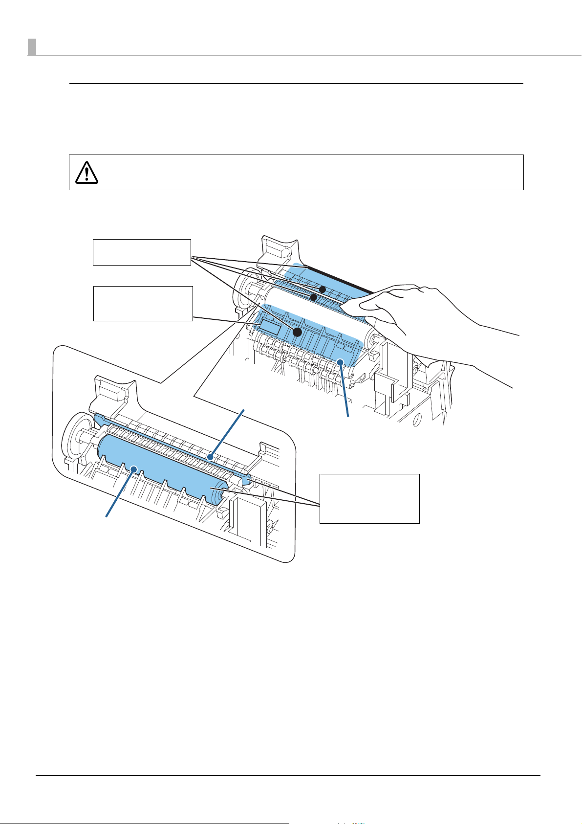
Cleaning paper path/autocutter/platen roller
Wipe off all glue on the ribs
and edges.
Blow or wipe off the paper
dust around the black mark
sensor.
Wipe off all glue on the
touchable area of the
autocutter and the platen
roller.
Paper path
Autocutter
Platen roller
Turn off the printer and open the roll paper cover. Clean the paper dust and adhesive substance
accumulated in the printer with a cotton swab or nonwoven fabric moistened with an alcohol solvent
(ethanol or IPA).
Do not touch the edge of the autocutter blade directly with your finger. Doing so may
WARNING
injure your finger.
70
Page 71

Preparing for Transport
Follow the procedures below to transport the printer.
Turn off the printer by operating the power switch.
1
Ensure that the LED has turned off.
2
Disconnect the power supply connector.
3
Remove the roll paper.
4
Pack the printer upright.
5
Chapter 5 Handling
71
5
Page 72

72
Page 73

Appendix
Product Specifications
Appendix
Printing method
Cutting type
Roll paper
width
Interface
Buffers Receive buffer
65* model
Other than the 65* model
Downloaded buffer
Macro buffer
Thermal line printing
Partial cut (cutting with one point in left edge left uncut)
Width 40 mm
Width 80 mm
Width 40 mm
Width 58 mm
Width 80 mm
USB: USB 2.0 Full-speed (12 Mbps)
Ethernet: 10BASE-T/100BASE-TX
Serial: RS-232
Wireless LAN: Connecting an optional Wireless LAN unit to the
USB connector.
4 KB/45 bytes (selectable using memory switch 1-2)
Downloaded bit image: Approximately 12 KB
User-defined characters: Approximately 11 KB
2 KB
*1
*1
NV (Non-volatile)
graphics data area:
User NV memory
Page mode area
Barcode/two-dimensional symbol
printing
Power supply
0 to384 KB
1 to192 KB
106 KB
UPC-A, UPC-E, JAN 8 (EAN 8), JAN 13 (EAN 13), CODE 39, ITF,
CODABAR (NW-7), CODE 93, CODE 128, PDF417, MaxiCode,
QRCode
Power supplied by the PS-180 AC adapter
73
Page 74

Life
*2 *3
Printer mechanism
Thermal paper: 20,000,000 lines
Liner-free label paper: 10,000,000 lines
Thermal head
Autocutter
Platen roller
*4
MTBF
*5
MCBF
Temperature/humidity
Thermal paper:150 million pulses, 150 km
Liner-free label paper: 75 million pulses, 75 km
Thermal paper: 2,000,000 cuts
Liner-free label paper: 1,000,000 cuts (at the glued area cut rate =
50%)
Liner-free label paper:
• 80 mm width paper: 16 km
• 58 mm width paper: 16 km
• 40 mm width paper: 56 km
360,000 hours
Thermal paper: 70,000,000 lines
Liner-free label paper: 35,000,000 lines
Thermal paper
• Operating: 5 to 45°C {41 to 113°F}, 10 to 90% RH
• Storage: -10 to 50°C {14 to 122°F}, 10 to 90% RH
Liner-free label paper
• Operating: 5 to 35°C {41 to 95°F}, 20 to 80% RH
• Storage: -10 to 50°C {14 to 122°F}, 10 to 90% RH
External dimensions (H × W × D)
Mass
*1: Liner-free label paper only
*2: Changes depending on the paper type and model to be used.
*3: Indicates the point at which the wear-out failure period starts.
*4: Indicates the mean time between failures during the random failure period.
*5: Indicates the overall mean time between failures, including wear-out and random failures, before the life is reached.
148 × 140 × 203 mm {5.83 × 5.51 × 7.99"}
Approximately 1.9 kg {4.19 lb} (roll paper excluded)
74
Page 75

Printing Specifications
40 mm width paper 58 mm width paper 80 mm width paper
Appendix
Printing method
Dot density
Printing direction
Maximum printable
area
Characters
per line*1
Maximum print
speed
(Standard
printing)
Font A
Font B
*2
Thermal line printing
203 × 203 dpi
Unidirectional with friction feed
35.0 mm {1.38"},
280 dot positions
Auto scaling
•Disabled: 23
•Enabled: 40
Auto scaling
•Disabled: 31
•Enabled: 40
Printing on thermal paper: 170 mm/s
52.5 mm {2.07"},
420 dot positions
Auto scaling
•Disabled: 30
•Enabled: 42
Auto scaling
•Disabled: 40
•Enabled: 60
*3
Printing on liner-free label paper: 90 mm/s
72.0 mm {2.83"},
576 dot positions
Compatible mode
• TM-T88 series (1): 42
• TM-T88 series (2): 44
• TM-L90: 48
Compatible mode
• TM-T88 series (1): 55
• TM-T88 series (2): 57
• TM-L90: 64
Line spacing
3.75 mm {0.15"}
40 mm width paper with auto scaling enabled: 1.75 mm {0.07"}
* Default setting, programmable by command
*1: Auto scaling and compatible mode are selectable using memory switch 6 ("Memory Switch 6" on page 40)
For the 67*/68* (multilingual) models, see auto scaling disabled/TM-L90 compatible mode.
*2: At 24 V, 25°C, with standard print density
*3: Maximum print speed changes in the following case:
- Vertical barcode/two-dimensional symbol printing: 90 mm/s
dpi: dots per inch
• To change the paper width, the 40 mm roll paper guide is required. (
Paper Width" on page 25)
• Because some parts of the print head and the autocutter blade may contact the platen
and become worn out, you cannot change a smaller paper width to a larger one once
you start using the product.
• Printing speed may be slower, depending on items such as the print data, head
temperature, and energization parting.
• As vertical barcodes and two-dimensional symbols are printed after the specified
speed is reached, paper may be fed unprinted for a maximum of 10 dot lines.
• For the 685 and 686 models, white lines may appear in the printing direction when
using graphics printing.
"Changing the
75
Page 76
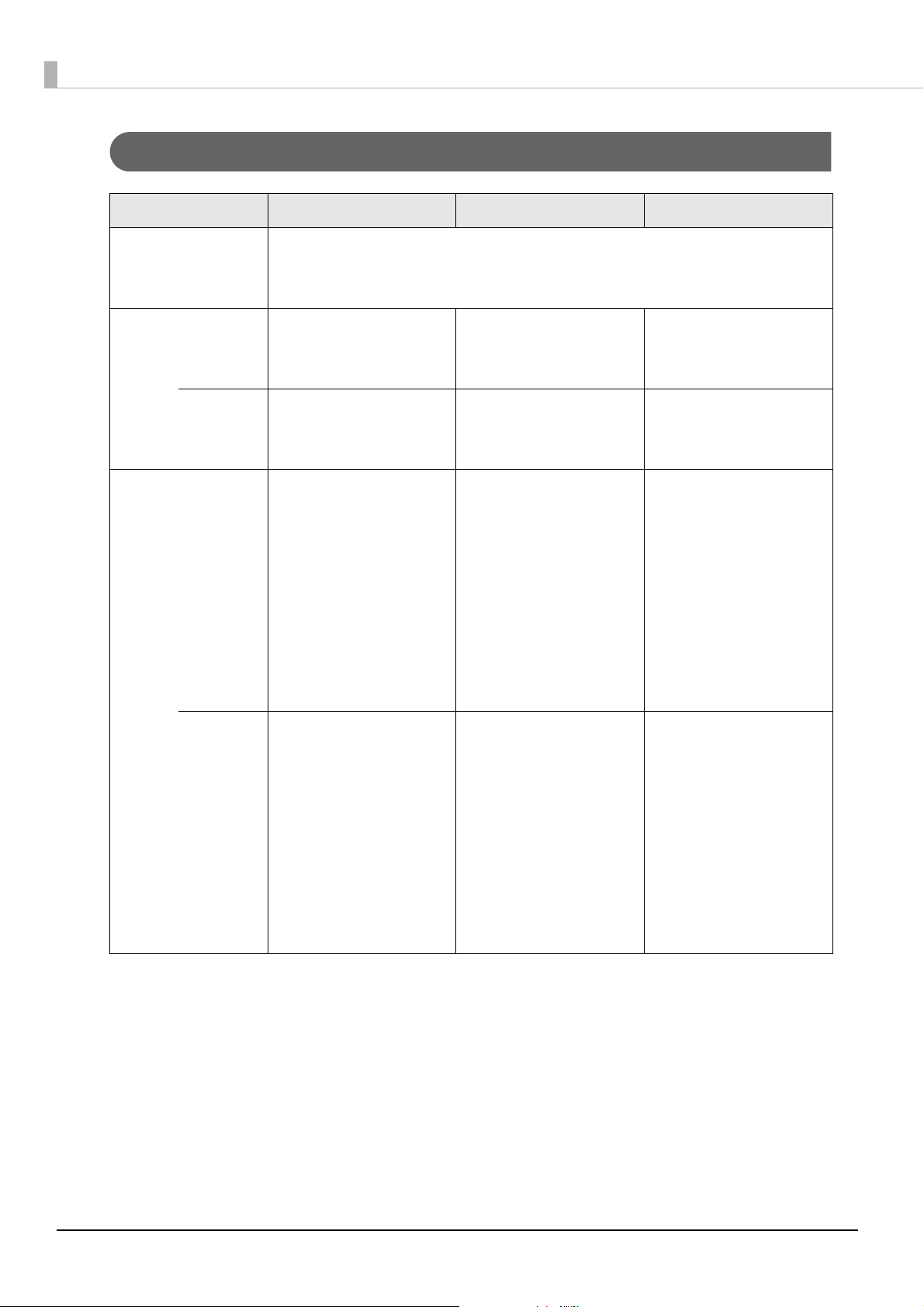
Character Specifications
40 mm width paper 58 mm width paper 80 mm width paper
Character type
*
Font A
Vertical dot)
Font B
(Horizontal dot x
Character structure
*
Font A
Character size*
(horizontal × vertical)
Alphanumeric characters: 95
Extended graphics: 128 × 11 pages (including user-defined page)
International character set: 37
Auto scaling
• Disabled: 12x24
• Enabled: 7x17
Auto scaling
•Disabled: 9x17
• Enabled: 7x17
Auto scaling
•Disabled:
12 × 24 mm {0.47 × 0.94”}/
12 × 48 mm {0.47 × 1.89”}/
24 × 24 mm {0.94 × 0.94”}/
24 × 48 mm {0.94 × 1.89”}
•Enabled:
7 × 17 mm {0.28 × 0.67”}/
7 × 34 mm {0.28 × 1.33”}/
14 × 17 mm {0.55 × 0.67”}/
12 × 24 mm {0.47 × 0.94”}
Auto scaling
• Disabled: 13x24
• Enabled: 10x24
Auto scaling
• Disabled: 10x17
• Enabled: 7x17
Auto scaling
•Disabled:
13 × 24 mm {0.51 × 0.94”}/
13 × 48 mm {0.94 × 1.89”}/
26 × 24 mm {1.02 × 0.94”}/
26 × 48 mm {1.02 × 1.89”}
•Enabled:
10 × 24 mm {0.39 × 0.94”}/
10 × 48 mm {0.39 × 1.89”}/
20 × 24 mm {0.79 × 0.94”}/
20 × 48 mm {0.79 × 1.89”}
Compatible mode
• TM-T88 series: 13 × 24
• TM-L90: 12 × 24
Compatible mode
• TM-T88 series: 10x17
• TM-L90: 9 × 17
Compatible mode
• TM-T88 series:
13 × 24 mm {0.51 × 0.94”}/
13 × 48 mm {0.94 × 1.89”}/
26 × 24 mm {0.94 × 1.89”}/
26 × 48 mm {1.02 × 1.89”}
•TM-L90:
12 × 24 mm {0.47 × 0.94”}/
12 × 48 mm {0.47 × 1.89”}/
24 × 24 mm {0.94 × 0.94”}/
24 × 48 mm {0.94 × 1.89”}
Font B
Standard/double-height/double-width/double-width/double-height
*: Auto scaling and compatible mode are selectable using memory switch 6 ("Memory Switch 6" on page 40)
For the 67*/68* (multilingual) models, see auto scaling disabled, TM-L90 compatible mode.
Auto scaling
•Disabled:
9 × 17 mm {0.35 × 0.67”}/
9 × 34 mm {0.35 × 1.34”}/
18 × 17 mm {0.71 × 0.67”}/
18 × 34 mm {0.71 × 1.34”}
•Enabled:
7 × 17 mm {0.28 × 0.67”}/
7 × 34 mm {0.28 × 1.34”}/
14 × 17 mm {0.55 × 0.67”}/
12 × 34 mm {0.47 × 1.34”}
Auto scaling
•Disabled:
10 × 17 mm {0.39 × 0.67”}/
10 × 34 mm {0.39 × 1.34”}/
20 × 17 mm {0.79 × 0.67”}/
20 × 34 mm {0.79 × 1.34”}
•Enabled:
7 × 17 mm {0.28 × 0.67”}/
7 × 34 mm {0.28 × 1.34”}/
14 × 17 mm {0.55 × 0.67”}/
14 × 34 mm {0.55 × 1.34”}
Compatible mode
• TM-T88 series:
•TM-L90:
10 × 17 mm {0.39 × 0.67”}/
10 × 34 mm {0.39 × 1.34”}/
20 × 17 mm {0.79 × 0.67”}/
20 × 34 mm {0.79 × 1.34”}
9 × 17 mm {0.35 × 0.67”}/
9 × 34 mm {0.35 × 1.34”}/
18 × 17 mm {0.71 × 0.67”}/
18 × 34 mm {0.71 × 1.34”}
76
Page 77

Appendix
Note:
1. The actual print character may be smaller than the size shown in the table above, because the above sizes include spaces in the font.
2. Characters can be scaled up to 64 times as large as the standard sizes shown above.
3. Character size not including the horizontal spacing in the standard scale is as follows:
<Auto scaling disabled>
Font A (standard): 1.25 (W) × 3.00 (H) mm {0.05 (W) × 0.12 (H)”}
Font A (double-width/double-height): 2.50 (W) × 6.00 (H) mm {0.10 (W ) × 0.24 (H)”}
Font B (standard): 0.88 ( W) × 2.13 (H) mm {0.03 (W) × 0.08 (H)”}
Font B (double-width/double-height): 1.75 (W) × 4.25 (H) mm {0.07 (W) × 0.17 (H)”}
<Auto scaling enabled>
40 mm width paper
Font A (standard): 0.88 (W) × 2.13 (H) mm {0.03 (W) × 0.08 (H)”}
Font A (double-width/double-height): 1.25 (W) × 3.00 (H) mm {0.05 (W) × 0.12 (H)”}
Font B (standard): 0.88 ( W) × 2.13 (H) mm {0.03 (W) × 0.08 (H)”}
Font B (double-width/double-height): 1.75 (W) × 4.25 (H) mm {0.07 (W) × 0.17 (H)”}
58 mm width paper
Font A (standard): 1.125 (W) × 3.00 (H) mm {0.04 (W) × 0.12 (H)”}
Font A (double-width/double-height): 2.25 (W) × 6.00 (H) mm {0.09 (W) × 0.24 (H)”}
Font B (standard): 0.88 ( W) × 2.13 (H) mm {0.03 (W) × 0.08 (H)”}
Font B (double-width/double-height): 1.75 (W) × 4.25 (H) mm {0.07 (W) × 0.17 (H)”}
77
Page 78

Details of Characters Per Line and Character Specifications with Auto Scaling Enabled
Auto scaling automatically reduces print data that is outside the print area for 40/58 mm width paper to the
print area for 40 mm width paper. Details of characters per line and character specifications with auto
scaling enabled are as shown below.
• Enabled only when 40/58 mm width paper is used.
• Enabled/disabled by memory switch 6-8. (
"Memory Switch 6" on page 40)
MSW 6-8: OFF (40 mm/80 mm)
When using 40 mm width roll paper, received print data is automatically compressed in the vertical and
horizontal directions.
Font A
Compatible
mode
TM-T88 series
compatible
mode (1)
Print data to be scaled down by
auto scaling
Print area:
35.0 mm {1.38”}
Printed characters:
280 dots
MSW
6-4
MSW
6-5
Specified
character size
Receipt print data
Print area:
72.0 mm {2.83”}
Printed characters:
576 dots
ON ON Actual size Characters per line: 42 *1Character font: 7 × 17
Characters per line: 40
Double width/
Double height
(n × width) ×
(m × height)
(double width/
double height
excluded)
Characters per line: 21
Characters per line:
552 dots ÷ (13 × n)
The remainder is
rounded down.
*1
Character font: 12 × 24
Characters per line: 23
When n and m are both even
values
Character font:
*1
(12 × (n ÷ 2)) × (24 × (m ÷ 2))
Characters per line:
280 dots ÷ (12 × (n ÷ 2))
The remainder is rounded down.
*2
When neither n or m are even
values
Character font:
(7 × n) × (17 × m)
Characters per line:
280 dots ÷ (7 × n)
The remainder is rounded down.
*2
*2
78
Page 79

Appendix
Compatible
mode
TM-T88 series
compatible
mode (2)
Print data to be scaled down by
auto scaling
Print area:
35.0 mm {1.38”}
Printed characters:
280 dots
MSW
6-4
MSW
6-5
Specified
character size
Receipt print data
Print area:
72.0 mm {2.83”}
Printed characters:
576 dots
ON OFF Actual size Characters per line: 44 Character font: 7 × 17
Characters per line: 40
Double width/
Double height
(n × width) ×
(m × height)
(double width/
double height
excluded)
Characters per line: 22 Character font: 12 × 24
Characters per line: 23
Characters per line:
576 dots ÷ (13 × n)
The remainder is
rounded down.
When n and m are both even
values
Character font:
(12 × (n ÷ 2)) × (24 × (m ÷ 2))
Characters per line:
280 dots ÷ (12 × (n ÷ 2))
The remainder is rounded down.
*2
When neither n or m are even
values
Character font:
(7 × n) × (17 × m)
Characters per line:
280 dots ÷ (7 × n)
The remainder is rounded down.
*2
*2
79
Page 80

Receipt print data
Print data to be scaled down by
auto scaling
Compatible
mode
TM-L90
compatible
mode
MSW
6-4
Specified
character size
MSW
6-5
Print area:
72.0 mm {2.83”}
Printed characters:
576 dots
Print area:
35.0 mm {1.38”}
Printed characters:
280 dots
OFF OFF Actual size Characters per line: 48 Character font: 7 × 17
Characters per line: 40
Double width/
Double height
Characters per line: 24 Character font: 12 × 24
Characters per line: 23
(double width/
double height
excluded)
(n × width) ×
(m × height)
(double width/
double height
excluded)
Characters per line:
576 dots ÷ (12 × n)
The remainder is
rounded down.
When n and m are both even
values
Character font:
(12 × (n ÷ 2)) × (24 × (m ÷ 2))
Characters per line:
280 dots ÷ (12 × (n ÷ 2))
The remainder is rounded down.
*2
When neither n or m are even
values
Character font:
(7 × n) × (17 × m)
Characters per line:
280 dots ÷ (7 × n)
The remainder is rounded down.
*2
*2
*1: The print area is 68.25 mm {2.69”} and 552 dots.
*2: Only when Font A is specified and double width/double height is set, the font during auto scaling is 12 x 24.
80
Page 81

Font B
Appendix
Receipt print data Print data to be scaled down by
auto scaling
Compatible
mode
TM-T88 series
compatible
mode (1)
TM-T88 series
compatible
mode (2)
MSW
6-4
MSW
6-5
Specified
character size
Print area:
72.0 mm {2.83”}
Printed characters:
576 dots
Print area:
35.0 mm {1.38”}
Printed characters:
280 dots
ON ON Actual size Characters per line: 55 *1Character font: 7 × 17
Characters per line: 40
Double width/
Double height
(n × width) ×
(m × height)
(double width/
double height
excluded)
Characters per line: 27
Characters per line:
552 dots ÷ (10 × n)
The remainder is
rounded down.
*1
Character font: 14 × 34
Characters per line: 20
Character font:
(7 × n) × (17 × m)
*1
Characters per line:
280 dots ÷ (7 × n)
The remainder is rounded down.
ON OFF Actual size Characters per line: 57 Character font: 7 × 17
Characters per line: 40
Double width/
Double height
(n × width) ×
(m × height)
(double width/
double height
excluded)
Characters per line: 28 Character font: 12 × 34
Characters per line: 20
Characters per line:
576 dots ÷ (10 × n)
The remainder is
rounded down.
Character font:
(7 × n) × (17 × m)
Characters per line:
280 dots ÷ (7 × n)
The remainder is rounded down.
TM-L90
OFF OFF Actual size Characters per line: 64 Character font: 7 × 17
compatible
mode
Double width/
Double height
(n × width) ×
(m × height)
(double width/
double height
excluded)
*1: The print area is 68.25 mm {2.69”} and 552 dots.
Characters per line: 40
Characters per line: 32 Character font: 14 × 34
Characters per line: 20
Characters per line:
576 dots ÷ (9×n)
The remainder is
rounded down.
Character font:
(7 × n) × (17 × m)
Characters per line:
280 dots ÷ (7 × n)
The remainder is rounded down.
81
Page 82
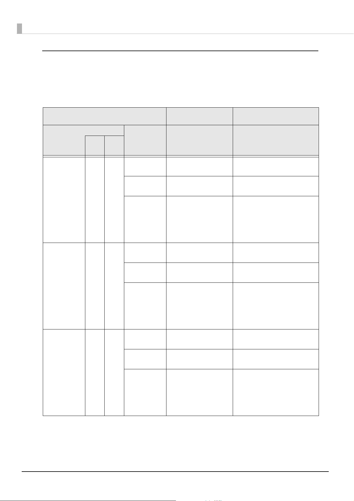
MSW 6-8: ON (58 mm/80 mm)
When using 58 mm width roll paper, received print data is automatically compressed in the vertical and
horizontal directions.
Font A
Receipt print data Print data to be scaled down by
auto scaling
Compatible
mode
TM-T88 series
compatible
mode (1)
TM-T88 series
compatible
mode (2)
MSW
6-4
MSW
6-5
Specified
character size
Print area:
72.0 mm {2.83”}
Printed characters:
576 dots
Print area:
52.5 mm {2.07”}
Printed characters:
420 dots
ON ON Actual size Characters per line: 42 *1Character font: 10 × 24
Characters per line: 42
Double width/
Double height
(n × width) ×
(m × height)
(double width/
double height
excluded)
Characters per line: 21
Characters per line:
552 dots ÷ (10 × n)
The remainder is
rounded down.
*1
Character font: 20 × 48
Characters per line: 21
Character font:
(10 × n) × (24 × m)
*1
Characters per line:
420 dots ÷ (10 × n)
The remainder is rounded down.
ON OFF Actual size Characters per line: 44 Character font: 10 × 24
Characters per line: 42
Double width/
Double height
(n × width) ×
(m × height)
(double width/
double height
excluded)
Characters per line: 22 Character font: 20 × 48
Characters per line: 21
Characters per line:
576 dots ÷ (10 × n)
The remainder is
rounded down.
Character font:
(10 × n) × (24 × m)
Characters per line:
420 dots ÷ (10 × n)
The remainder is rounded down.
TM-L90
OFF OFF Actual size Characters per line: 48 Character font: 10 × 24
compatible
mode
*1: The print area is 68.25 mm {2.69”} and 552 dots.
82
Double width/
Double height
(n × width) ×
(m × height)
(double width/
double height
excluded)
Characters per line: 42
Characters per line: 24 Character font: 20 × 48
Characters per line: 21
Characters per line:
576 dots ÷ (10×n)
The remainder is
rounded down.
Character font:
(10 × n) × (24 × m)
Characters per line:
420 dots ÷ (10 × n)
The remainder is rounded down.
Page 83

Font B
Appendix
Receipt print data Print data to be scaled down by
auto scaling
Compatible
mode
TM-T88 series
compatible
mode (1)
TM-T88 series
compatible
mode (2)
MSW
6-4
MSW
6-5
Specified
character size
Print area:
72.0 mm {2.83”}
Printed characters:
576 dots
Print area:
52.5 mm {2.07”}
Printed characters:
420 dots
ON ON Actual size Characters per line: 55 *1Character font: 7 × 17
Characters per line: 60
Double width/
Double height
(n × width) ×
(m × height)
(double width/
double height
excluded)
Characters per line: 27
Characters per line:
552 dots ÷ (7 × n)
The remainder is
rounded down.
*1
Character font: 14 × 34
Characters per line: 30
Character font:
(7 × n) × (17 × m)
*1
Characters per line:
420 dots ÷ (7 × n)
The remainder is rounded down.
ON OFF Actual size Characters per line: 57 Character font: 7 × 17
Characters per line: 60
Double width/
Double height
(n × width) ×
(m × height)
(double width/
double height
excluded)
Characters per line: 28 Character font: 14 × 34
Characters per line: 20
Characters per line:
576 dots ÷ (7 × n)
The remainder is
rounded down.
Character font:
(7 × n) × (17 × m)
Characters per line:
420 dots ÷ (7 × n)
The remainder is rounded down.
TM-L90
OFF OFF Actual size Characters per line: 64 Character font: 7 × 17
compatible
mode
Double width/
Double height
(n × width) ×
(m × height)
(double width/
double height
excluded)
*1: The print area is 68.25 mm {2.69”} and 552 dots.
Characters per line: 60
Characters per line: 32 Character font: 14 × 34
Characters per line: 20
Characters per line:
576 dots ÷ (7×n)
The remainder is
rounded down.
Character font:
(7 × n) × (17 × m)
Characters per line:
420 dots ÷ (7 × n)
The remainder is rounded down.
83
Page 84

When receiving 512-dot print data for TM-T88 series models
If 512-dot print data for TM-T88 series models is received when using 58 mm width roll paper, it is
automatically compressed in the vertical and horizontal directions.
Font A
Receipt print data Print data to be scaled down by
auto scaling
Compatible
mode
MSW
Any mode ON/
Font B
Compatible
mode
Any mode ON/
MSW
6-4
OFF
6-4
OFF
MSW
6-5
ON/
OFF
MSW
6-5
ON/
OFF
Specified
character size
Print area:
72.0 mm {2.83”}
Printed characters:
512 dots
Print area:
52.5 mm {2.07”}
Printed characters:
420 dots
Actual size Characters per line: 42 Character font: 10 × 24
Characters per line: 42
(n × width) ×
(m × height)
(double width/
double height
excluded)
Specified
character size
Characters per line:
512 dots ÷ (10 × n)
The remainder is
rounded down.
Character font:
(10 × n) × (24 × m)
Characters per line:
420 dots ÷ (10 × n)
The remainder is rounded down.
Receipt print data Print data to be scaled down by
auto scaling
Print area:
72.0 mm {2.83”}
Printed characters:
512 dots
Print area:
52.5 mm {2.07”}
Printed characters:
420 dots
Actual size Characters per line: 60 Character font: 7 × 17
Characters per line: 60
84
(n × width) ×
(m × height)
(double width/
double height
excluded)
Characters per line:
512 dots ÷ (7 × n)
The remainder is
rounded down.
Character font:
(7 × n) × (17 × m)
Characters per line:
420 dots ÷ (7 × n)
The remainder is rounded down.
Page 85

Paper Specifications
Appendix
Paper type
Form
Size Paper width
Specified roll paper type
no.:
(liner-free label paper)
*2
Roll paper
diameter
Roll paper
spool
diameter
Roll width
when taken
up
40 mm width paper
*1
58 mm width paper 80 mm width paper
• Thermal paper
• Liner-free label paper
Roll paper
Width 39.5 ± 0.5 mm
{1.56 ± 0.02”}
Width 57.5 ± 0.5 mm
{2.24 ± 0.02”}
Max. diameter: 102 mm {4.02”}
• Thermal paper: 18 mm {0.71”} or more
• Liner-free label paper: 31.8 mm {1.25”}
• Liner-free label paper:
39.5 + 1.044/-0.5 mm
{1.56 + 0.04/-0.02”}
• Thermal paper: 57.5 +
1/-0.5 mm {2.26 +
0.04/-0.02”}
• Liner-free label paper:
57.5 +1.2/-0.5 mm
{2.26 + 0.05/-0.02”}
• 9023–1275
Lane Coated: 6 rolls
• 9023–1257
Lane Coated: 12 rolls
(Iconex(USA))
• 9023–1823
Lane Coated: 12 rolls
• 9023–1397
Lane Coated: 30 rolls
(Iconex(USA))
Width 79.5 ± 0.5 mm
{3.13 ± 0.02”}
• Thermal paper:
79.5 +1/-0.5 mm {3.13
+ 0.04/-0.02”}
• Liner-free label paper:
79.5 +1.0/-0.5 mm
{3.13 + 0.04/-0.02”}
• 9023–1274
Lane Coated: 6 rolls
• 9023–1253
Lane Coated: 12 rolls
(Iconex(USA))
Specified original paper
type no.:
(Thermal paper)
• TF50KS-EY NIPPON Paper Industries Co., Ltd.)...Specified paper
• P35524 (Kanzaki Specialty Papers (USA))
• P31523 (Kanzaki Specialty Papers (USA))
• P30523 (Kanzaki Specialty Papers (USA))
• F5041(55) (Mitsubishi HiTec Paper Flensburg gmbH (Germany))
• KF50 (KANZAN Spezialpapiere gmbH)
• KT55FA (Papierfabrik August Koehler SE (Germany))
• KT48FA (Papierfabrik August Koehler SE (Germany))
• AF50KS-E (Jujo Thermal Ltd (Finland))
*1: Liner-free label paper only
*2: The paper type is automatically detected by whether black marks exist or not.
• Paper must not be pasted to the roll paper spool.
• For the best print quality and reliability for each paper type, it is recommended to set
the print density (
"Selection of printing density" on page 43).
85
Page 86

Black mark printing specifications for liner-free label paper
Permitted preprint area
2
1
15.0 {0.59”}
2.39 {0.09”}
Paper feed direction
Back (non-printing side)
Units: mm
Glued area
23.01 {0.91”}
Paper width 57.5 ± 0.5 mm {2.26 ± 0.02”} or
79.5 ± 0.5 mm {3.13 ± 0.02”}
2.38 {0.09”}
17.5 {0.69”}
25.4 {1”}
12.7 ± 1.58 {0.50 ± 0.06”}
3.18 {0.13”}
When using liner-free label paper, the paper must meet the following conditions:
• Black marks are printed on the back side (non-printing side)
• The combination of reflection rate of each area satisfies the table below.
Note: Reflection rates are measured by the Macbeth PCM-II (Filter D). The back of the paper is measured.
Reflection rate of black mark area (1) 17% or
less
Reflection rate of area outside black
mark (2)
90% or
more
80/58 mm width paper
16% or
less
85% or
more
15% or
less
80% or
more
14% or
less
75% or
more
13% or
less
70% or
more
86
Page 87

40 mm width paper
Permitted preprint area
2
1
15.0 {0.59”}
2.39 {0.09”}
Paper feed direction
Back (non-printing side)
Units: mm
Glued area
20.6 {0.81”}
Width 39.5 ± 0.5 mm {1.56 ± 0.02”}
2.38 {0.09”}
12.7 {0.50”}
25.4 {1”}
12.7 ± 1.58 {0.50 ± 0.06”}
3.18 {0.13”}
Appendix
87
Page 88

Thermal paper specifications
Permitted preprint area
Prohibited preprint area
15.0 {0.59”}
Paper feed direction
Back (non-printing side)
Units: mm
Paper width 57.5 ± 0.5 mm {2.26 ± 0.02”} or
79.5 ± 0.5 mm {3.13 ± 0.02”}
When using thermal paper, the paper must meet the following conditions:
Non-printing side
• Black marks or similar marks are NOT printed on the back (non-printing side)
• The reflection rate of prohibited preprint area is 70% or more
Note: Reflection rates are measured by the Macbeth PCM-II (Filter D). The back of the paper is measured.
88
Page 89

Printing side
Prohibited preprint area
15.0 {0.59”}
Paper feed direction
Front (printing side)
Units: mm
Paper width 57.5 ± 0.5 mm {2.26 ± 0.02”} or
79.5 ± 0.5 mm {3.13 ± 0.02”}
5.0 {0.20”}
• No preprint in the area shown below
Appendix
89
Page 90

Printable Area
79.5 ± 0.5 mm {3.13 ± 0.02”}
0.125 mm {0.005”}
72 mm {2.83”}
576 dots
(2.65 mm {0.10”} ) (4.85 mm {0.19”})
0.125 mm
{0.005”}
420 dots
52.5 mm {2.07”}
(2.65 mm (4.85 mm
{0.10”} ) {0.09”})
57.5 ± 0.5 mm {2.26 ± 0.02”}
The print area may be out of alignment by 2 mm {0.08”} maximum to the left or right. When setting the
print area, refer to the table and figure below to allow enough margins to the left and right.
Paper width
(mm)
Printable area 72 {2.83”} 64 {2.52”} 59 {2.32”} 54 {2.13”} 52 {2.05”} 44 {1.73”} 39 {1.54”} 32 {1.26”}
Lef t m argin 2.65 {0.10”} 2.65 {0.10”} 2.65 {0.10”} 2.65 {0.10”} 2.65 {0.10”} 2.65 {0.10”} 2.65 {0.10”} 2.65 {0.10”}
Right ma rgin 4.85 {0.19”} 2.85 {0.11”} 2.85 {0.11”} 2.85 {0.11”} 2.85 {0.11”} 2.85 {0.11”} 2.85 {0.11”} 2.85 {0.11”}
Total number of
dots
80 70 65 60 58 50 45 38
576 512 472 432 416 352 312 256
Units: mm
80 mm width paper
58 mm width paper
90
Page 91

40 mm width paper
40.0 ± 0.5 mm {1.57 ± 0.02”}
0.125 mm
{0.005”}
35 mm {1.38”}
(2.65 mm (2.35 mm
{0.10”} ) {0.09”})
280 dots
Appendix
91
Page 92

Printing and Cutting Positions
Autocutter blade position
Approx. 29 mm {1.14”}
Approx. 14 mm {0.55”}
Manual cutter position
Paper feed direction
Center of the print dotline
Autocutter blade position
Approx. 29 mm
{1.14”}
Approx.
14 mm
{0.55”}
Manual cutter position
Paper feed direction
Center of the print dotline
Print start position
Approx. 4 mm
{0.16”}
• The values above may vary slightly as a result of paper slack or variations in the paper.
Take this into account when setting the cutting position of the autocutter.
• To prevent paper jams and for the best print quality, it is recommended to feed the
paper by 1 mm {0.04”} or more after a paper cut.
The printing and autocutting positions change depending on the paper type or the
software setting. (
"Printing and Cutting Positions With Software Setting" on page 96)
Non-68* models/68* models with paper removal standby disabled
68* models with paper removal standby enabled
The print start position is adjustable with back feed.
92
Page 93

Electrical Characteristics
Appendix
Supply voltage
Current
consumption
(at 24 V, 25°C with
standard print
density)
Standby
Operating
DC 24 V ± 7%
Average: Approx. 0.1 A
Maximum 1 A for drawer kick driving.
Average: Approx. 1.8 A
Note: According to the following operation conditions:
• Font A
•44 digits
• ASCII character continuous 50 lines + 5-line paper feeding +
autocutting
(Repetition from 20h to 7Fh)
93
Page 94

Environmental Conditions
Thermal paper Liner-free label paper*
Operating
Storage
Temperature/Humidity
When
packed:
Vibration resistance
5 to 45°C {41 to 113°F}, 10 to 90% RH, noncondensing (See the operating
environment range below.)
-10 to 50°C {14 to 122°F}, 10 to 90%RH
(paper excluded)
Frequency: 5 to 55 Hz
Acceleration: Approximately 19.6 m/s² {2G}
Sweep: 10 minutes (half cycle)
Duration: 1 hour
Directions: XYZ
There is no external or internal visible damage and the unit operates normally after
being subjected to vibration.
5 to 35°C {41 to 95°F}, 20 to 80% RH, noncondensing (See the operating
environment range below.)
-10 to 50°C {14 to 122°F}, 10 to 90%RH
(paper excluded)
When
packed:
Impact resistance
When
unpacked:
Operating
Acoustic noise
Package: EPSON standard package
Height: 60 cm {23.62"}
Directions: corner, 3 edges, and 6 surfaces
There is no external or internal visible damage and the unit operates normally after
being dropped.
Height: 5 cm
Directions: Lift one edge and release it
There is no external or internal visible damage and the unit operates normally after
being dropped while not operating.
Approximately 52 dB (ANSI Bystander position)
NOTE) The values above are measured in the Epson evaluation condition.
Acoustic noise differs depending on the paper used, printing contents, and the setting
values, such as print speed or print density.
*: When the specified roll paper type is used ("Paper Specifications" on page 85)
94
Page 95

External Dimensions and Mass
203 {7.99”}
140 {5.51”}
148 {5.83”}
Units: mm
• Height: 148 mm {5.83”}
• Width: 140 mm {5.51”}
• Depth: 203 mm {7.99”}
• Mass: Approximately 1.9 kg {4.19 lb} (roll paper excluded)
Appendix
95
Page 96

Printing and Cutting Positions With Software Setting
The printing and autocutting positions change depending on the paper type or the software setting.
("Software Settings" on page 37
)
SW setting
Paper
Liner-free label
paper
Thermal paper - Specified
Paper removal standby Enabled Disabled
Stop position for
cutting
Auto top margin scaling - Disabled Enabled Disabled Enabled
MSW6-1 Cut at black
mark position
MSW6-1 Cut regardless
of black mark position
- Arbitrary stop position Specific stop position
Pattern A Pattern A Pattern D Pattern A Pattern D
Specified
by
command
by
command
Specified
by
command
Specified
by
command
Pattern C Pattern B Pattern C
Pattern E --
96
Page 97

Pattern A
Actual autocut position
(Black mark position)
Position where autocutting is set
(Specified by command)
End of printing
Back (non-printing side)
Appendix
Top margin of next label
SW setting
Paper
Liner-free label
paper
• Autcutting is performed at the black mark position that is below the end-of-printing
• When autocutting is executed by an autocutting command along with paper feeding,
• For information on continuous multiple label printing, see "Pattern D" on page 100
Paper removal standby Enabled Disabled
Stop position for cutting
Auto top margin scaling - Disabled Disabled
MSW6-1 Cut at black mark
position
position. If the autocutting position is close to the black mark, the black mark may be
skipped and autocutting may be performed at the next black mark position due to paper
slack or variations in the paper, or differences in an individual printer.
autocutting is performed at the black mark position that is below the position where
autocutting is set.
-
4 mm
{0.16”}
Arbitrary stop
position
Approx. 14 mm
{0.55”}
Paper width 40 mm:
approx. 24 mm {0.94”}
Paper width 80 mm:
approx. 26 mm {1.02”}
Specific stop position
.
97
Page 98

Pattern B
Actual autocut position
After feeding the paper to the specific stop
position specified by the factory setting,
the printer automatically performs
autocutting.
Position where autocutting is set
(Specified by command)
End of printing
Top margin of next label
SW setting
Paper
Liner-free label
paper
Paper removal standby Disabled
Stop position for cutting Arbitrary stop
Auto top margin scaling Disabled Disabled
MSW6-1 Cut at black
mark position
• If the printer has received print data for the next label at the time of autocutting, the printer
performs autocutting at the position specified by command.
When the printer has not received print data for the next label, the printer automatically
feeds the paper to the specific stop position (fixed at the factory before shipping) below
the end-of-printing position, and performs autocutting. This may make the bottom margin
larger than the one based on the position where autocutting is set.
• The specific stop position is determined by the position where a black mark is detected.
Therefore, if the autocutting position is close to the specific stop position, the printer feeds
the paper to the next specific stop position and performs autocutting, due to paper slack or
variations in the paper, or differences in an individual printer.
• When autocutting is executed by an autocutting command along with paper feeding,
autocutting is performed after paper is fed to the specific stop position that is below the
paper feed position specified by command.
• For information on continuous multiple label printing, see "Pattern C" on page 99
position
4 to 14 mm
{0.16 to 0.55”}
Specific stop position
Paper width 40 mm: approx. 14 mm {0.55”}
Paper width 80 mm: approx. 16 mm {0.63”}
.
98
Page 99

Pattern C
Top margin =14 mm {0.55”}
Top margin = 14 mm {0.55”}
Bottom margin = User-defined value
When the printer has the next print data, including data that
can be printed immediately after autocutting, the printer
cuts the paper at the position specified by the user-defined
value.
When the label is shorter than 35 mm {1.38”} long, the
printer feeds the paper so that the label is 35-mm {1.38”}
long minimum, and performs autocutting.
When auto top margin scaling is enabled, the top margin is
reduced automatically.
Bottom margin = User-defined value + 0 to 25.4 mm {0 to 1”}
* If the stop position for autocutting is set to a specific
position, the printer feeds the paper to the cut position and
performs autocutting.
*If the stop position for autocutting is set to an arbitrary stop
position, the printer performs autocutting at the position
specified by the user-defined value.
Print on the first label
Print on the second
label
Print on the third
label
Print on the first label
(Next sheet)
Print on the second
label (Next sheet)
Print on the third
label (Next sheet)
When the printer receives
print data for 3 labels
continuously
Position where autocutting
is set
Actual autocut position
*When the stop position for
autocutting is set to a
specific stop position
When the printer receives
print data for 3 labels again
Autocutting is performed at the specified paper cut position. However, when the label length is shorter
than 35 mm {1.38”}, the printer feeds the paper to the point where the label length is 35 mm {1.38”}, and
then performs autocutting.
Appendix
99
Page 100

Pattern D
Top mar gin
When the stop position for autocutting is set to a specific stop
position:
Approx. 24 mm {0.94”} when using 40 mm width liner-free
label paper
Approx. 26 mm {1.02”} when using 80 mm width liner-free
label paper
When the stop position for autocutting is set to an arbitrary stop
position
14 mm {0.55”}
When auto top margin scaling is enabled, the
top margin is reduced automatically.
Bottom margin = User-defined value + 0 to 25.4
mm {0 to 1”}
* To ensure cutting at the top edge of the black
mark, the printer automatically feeds the paper to
the autocut position, and performs autocutting.
Specified autocutting
position
Actual autocut position
When the printer receives
print data for 3 labels
continuously
Specified autocutting
position
Actual autocut position
Specified autocutting
position
Actual autocut position
Print on the first label
Print on the second
label
Print on the third
label
Print on the first label
(Next sheet)
Autocutting is performed at the black mark position.
100
 Loading...