

Describes how to control the printer and necessary information
when you develop applications.
Describes setup and installation of the product and peripherals.
Describes how to handle the product.
Describes character code tables.
Describes features and general specifications for the product.
Technical Reference Guide
Product Overview
Setup
Application Development Information
Handling
Appendix
M00059604
Rev. E

Cautions
• No part of this document may be reproduced, stored in a retrieval system, or transmitted in any form
or by any means, electronic, mechanical, photocopying, recording, or otherwise, without the prior
written permission of Seiko Epson Corporation.
• The contents of this document are subject to change without notice. Please contact us for the latest
information.
• While every precaution has been taken in the preparation of this document, Seiko Epson Corporation assumes no responsibility for errors or omissions.
• Neither is any liability assumed for damages resulting from the use of the information contained
herein.
• Neither Seiko Epson Corporation nor its affiliates shall be liable to the purchaser of this product or third
parties for damages, losses, costs, or expenses incurred by the purchaser or third parties as a result of:
accident, misuse, or abuse of this product or unauthorized modifications, repairs, or alterations to this
product, or (excluding the U.S.) failure to strictly comply with Seiko Epson Corporation’s operating
and maintenance instructions.
• Seiko Epson Corporation shall not be liable against any damages or problems arising from the use of
any options or any consumable products other than those designated as Original EPSON Products or
EPSON Approved Products by Seiko Epson Corporation.
Trademarks
EPSON is a registered trademark of Seiko Epson Corporation.
Exceed Your Vision and ESC/POS are registered trademarks or trademarks of Seiko Epson Corporation.
Microsoft
tion in the United States and other countries.
microSD is registered trademarks of SD Card Association.
Wi-Fi, WPATM, and WPA2TM are either registered trademarks or trademarks of Wi-Fi Alliance.
All other trademarks are the property of their respective owners and used for identification purpose
only.
and Internet Explorer are either registered trademarks or trademarks of Microsoft Corpora-
ESC/POS® Command System
EPSON has been taking industry’s initiatives with its own POS printer command system (ESC/POS).
ESC/POS has a large number of commands including patented ones. Its high scalability enables users
to build versatile POS systems. The system is compatible with all types of EPSON POS printers (excluding
the TM-C100) and displays. Moreover, its flexibility makes it easy to upgrade the future. The functionality
and the user-friendliness is valued around the world.
© Seiko Epson Corporation 2013-2015. All rights reserved.
2
For Safety
Key to Symbols
The symbols in this manual are identified by their level of importance, as defined below. Read
the following carefully before handling the product.
You must follow warnings carefully to avoid serious bodily injury.
WARNING
Provides information that must be observed to prevent damage to the equipment or loss of
data.
CAUTION
Possibility of sustaining physical injuries.
Possibility of causing physical damage.
Possibility of causing information loss.
Provides information that must be observed to avoid damage to your equipment or a
malfunction.
Provides important information and useful tips.
3

Warnings
WARNING
To avoid risk of electric shock, do not set up this product or handle cables during
a thunderstorm
Never insert or disconnect the power plug with wet hands.
Doing so may result in severe shock.
Handle the power cable with care.
Improper handling may lead to fire or electric shock.
Do not modify or attempt to repair the cable.
Do not place any heavy object on top of the cable.
Avoid excessive bending, twisting, and pulling.
Do not place the cable near heating equipment.
Check that the plug is clean before plugging it in.
Be sure to push the plug all the way in.
Be sure to use the specified power source.
Connection to an improper power source may cause fire or shock.
Do not place multiple loads on the power outlet.
Overloading the outlet may lead to fire.
Shut down your equipment immediately if it produces smoke, a strange odor, or
unusual noise.
Continued use may lead to fire. Immediately unplug the equipment and contact your
dealer or a Seiko Epson service center for advice.
Never attempt to repair this product yourself.
Improper repair work can be dangerous.
Never disassemble or modify this product.
Tampering with this product may result in injury or fire.
Do not allow foreign matter to fall into the equipment.
Penetration by foreign objects may lead to fire.
If water or other liquid spills into this equipment, do not continue to use it.
Continued use may lead to fire. Unplug the power cord immediately and contact your
dealer or a Seiko Epson service center for advice.
If you open the DIP switch cover, be sure to close the cover and tighten the screw
after adjusting the DIP switch.
Using this product with the cover open may cause fire or electric shock.
Do not use aerosol sprayers containing flammable gas inside or around this
product.
Doing so may cause fire.
4

Cautions
CAUTION
Do not connect cables in ways other than those mentioned in this manual.
Different connections may cause equipment damage or fire.
Be sure to set this equipment on a firm, stable, horizontal surface.
The product may break or cause injury if it falls.
Do not use this product in locations subject to high humidity or dust levels.
Excessive humidity and dust may cause equipment damage or fire.
Do not place heavy objects on top of this product. Never stand or lean on this
product.
Equipment may fall or collapse, causing breakage and possible injury.
Take care not to injure your fingers on the manual cutter
When you remove printed paper
When you perform other operations such as loading/replacing roll paper
Do not open the roll paper cover without taking the necessary precautions, as this
can result in injury from the autocutter fixed blade.
To ensure safety, unplug this product before leaving it unused for an extended
period.
When connecting external devices to the USB (including Micro-USB) connectors,
follow the precautions below.
Confirm the rated current of the external devices by checking the descriptions on the
devices or manuals. Do not use a device whose rated current is unclear.
Use the UL-approved external devices (only for North American users).
Connect the external devices only when those total rated current is less than 2.0A.
5
Wireless LAN (OT-WL01) Important Safety Information
May exert electromagnetic interference on, and cause malfunction of, cardiac
pacemakers.
WARNING
CAUTION
Before using this product, check that there is no one in the vicinity using a cardiac
pacemaker.
May exert electromagnetic interference on, and cause malfunction of, sensitive
medical equipment.
Before using this product, check that there is no sensitive medical equipment in the
vicinity.
Use of this product on aircraft may be restricted in some countries.
Before using this product, check that use of this product is not restricted on the aircraft.
Never attempt to repair this product yourself.
Improper repair work can be dangerous.
Never disassemble or modify this product.
Tampering with this product may result in injury or fire.
OT-WL01 is only for indoor use.
OT-WL01 should only be used for EPSON TM Intelligent Printers.
If it is installed on another device, it may result in computer failure, damage, or
malfunctions.
To comply with RF exposure compliance requirements, a distance of at least 20
cm must be maintained at all times between the antenna of OT-WL01 and people in
the vicinity.
Do not store in locations with high temperatures or high humidity.
It may in particular be damaged or deformed if left in a vehicle with the windows shut, or
placed in locations with unusually high temperatures for extended periods such as in
direct sunlight.
Do not get OT-WL01 wet.
This may cause malfunctions to occur.
Do not use near microwave ovens.
Wireless communication may be interrupted by electromagnetic interference generated
by microwave ovens.
Do not drop it, subject it to shocks, or place heavy objects on it.
Wireless LAN (OT-WL01) Usage Precautions
Wireless Telegraphy Act Regulations
The following acts are prohibited by the Wireless Telegraphy Act.
•Modifying and disassembling (including the antenna)
•Removing the label of conformance
6

Notes on Security when Using Wireless LAN
(Important information on customer rights (maintaining privacy)
The advantage of using a wireless LAN over a LAN cable is that, because information is
exchanged using radio signals, you can easily connect to the network if you are within range of
the radio signals. A disadva
signals can pass through barriers such as walls, so that if security countermeasures are not
implemented in some way, problems such as the following may occur.
•Communication data can be intercepted
A third party may be able t
could obtain personal information from these transmissions such as IDs, passwords, or credit
card numbers, or they could intercept the contents of personal e-mail messages.
•Unauthorized access to the network
third party could access an individual or intra-company network without permission and
A
carry out any of the following activities.
Retrieve personal data or other secret information (information leakage)
Pose as another user and send inappropriate data (impersonation)
Overwrite the contents of intercepted data and resend it (falsification)
Introduce a computer virus which could cause data loss or system crashes (damage)
Initially, the possibility that such problems could occur through settings concerning the
security of the wireless LAN product and by using the product are decreased, because the
wireless LAN card and the access point have security measures to deal with these problems.
We recom m e nd that you use this product
judgement and assuming full responsibility, a nd with your full understanding of problems
that may occur if you do not make any security settings.
ntage of this is that within a certain range, the electromagnetic
o receive wireless transmissions without authorization, and they
after making security settings using our own
Notes on Setting SSID (Service Set Identifier)
For protection of security, note the following precautions when setting the SSID.
•Change the SSID from the default setting.
•Do not set texts by which the owner can be identified as the SSID.
Notes on Setting Cryptographic Key
For protection of security, note the following precautions when setting the cryptographic key.
•Avoid using words on a dictionary as practicably as possible.
•Combine meaningless alphanumeric characters and symbols.
•Use texts consisted of at least 13 characters or more or of 20 characters or more if possible.
7

Restriction of Use
When this product is used for applications requiring high reliability/safety, s uch as
transportation devices related to aviation, rail, marine, automotive, etc.; disaster prevention
devices; various safety devices, etc.; or functional/precision
product only after giving consideration to including fail-safes and redundancies into your
design to maintain safety and total system reliability. B e c a use this product was not intended for
use in applications requiring extremely high reliability/safety, s uch as aerospace equipment,
main communication equipment, nuclear power control equipment, or medical equipment
related to direct medical care, etc., please make your own judgment on this product's suitability
after a f
ull evaluation.
devices, etc., you should use this
8

About this Manual
Aim of the Manual
This manual was created to provide information on development, design, and installation of
receipt issue systems and development and design of printer applications for developers.
Manual Content
The manual is made up of the following sections:
Chapter 1
Chapter 2
Chapter 3
Chapter 4
Appendix
Product Overview
Setup
Application Development Information
Handling
Character Code Tables
9

Contents
■ For Safety .............................................................................................................................. 3
Key to Symbols........................................................................................................................................3
Warnings..................................................................................................................................................4
Cautions ..................................................................................................................................................5
Wireless LAN (OT-WL01) Important Safety Information.......................................................................6
Wireless LAN (OT-WL01) Usage Precautions ........................................................................................6
■ Restriction of Use .................................................................................................................. 8
■ About this Manual................................................................................................................ 9
Aim of the Manual .................................................................................................................................9
Manual Content .....................................................................................................................................9
■ Contents.............................................................................................................................. 10
Product Overview ........................................................................15
■ Features............................................................................................................................... 15
■ Product Configurations...................................................................................................... 17
Autocutter............................................................................................................................................. 17
Colors.....................................................................................................................................................17
Accessories ...........................................................................................................................................17
■ Part Names and Functions ................................................................................................ 18
Power Switch.........................................................................................................................................18
Power Switch Cover .............................................................................................................................19
Control Panel ........................................................................................................................................19
Connectors ........................................................................................................................................... 21
Offline.....................................................................................................................................................23
■ Error Status........................................................................................................................... 24
Automatically Recoverable Errors ...................................................................................................... 24
Recoverable Errors ...............................................................................................................................25
Unrecoverable Errors............................................................................................................................26
No Connection to External Devices................................................................................................... 27
■ NV Memory (Non-Volatile Memory) ................................................................................ 28
NV Graphics Memory ..........................................................................................................................28
User NV Memory...................................................................................................................................28
Memory Switches .................................................................................................................................28
User-defined Page................................................................................................................................28
Maintenance Counter.........................................................................................................................29
Paper layout settings............................................................................................................................29
10

■ Product Specifications .......................................................................................................30
Software Specifications....................................................................................................................... 31
Intelligent Section Specifications ....................................................................................................... 32
Printing Specifications ......................................................................................................................... 33
Character Specifications.................................................................................................................... 34
Paper Specifications............................................................................................................................ 35
Printable Area ...................................................................................................................................... 45
Printing and Cutting Positions............................................................................................................. 47
Electrical Characteristics .................................................................................................................... 48
Environmental Conditions................................................................................................................... 49
External Dimensions and Mass ........................................................................................................... 50
TM-L90-i Dedicated AC Adapter ....................................................................................................... 50
■ Option Specifications.........................................................................................................51
Wireless LAN Cable Set (OT-WL01)..................................................................................................... 51
Setup .............................................................................................53
■ Flow of Setup.......................................................................................................................53
■ Installing the Printer ............................................................................................................55
Control panel label for horizontal use ............................................................................................... 56
Installing the paper discharge guide ................................................................................................ 56
■ Changing the Paper Width ................................................................................................57
■ Adjusting the position of the roll paper near end detector............................................59
Adjustment procedure........................................................................................................................ 60
■ Setting the DIP Switches.....................................................................................................62
Setting Procedure................................................................................................................................ 62
■ Connecting the Cash Drawer............................................................................................63
Connecting the Drawer Kick-out Cable ........................................................................................... 63
■ Connecting the Power Supply Unit ...................................................................................65
Connecting the Power Supply Unit.................................................................................................... 65
■ Connecting the Printer to the System ...............................................................................67
For Ethernet Interface ......................................................................................................................... 67
For Wireless LAN Interface................................................................................................................... 69
■ Network Setting...................................................................................................................72
Wired LAN Setting ................................................................................................................................ 72
Wireless LAN Setting............................................................................................................................. 74
Confirming Network Setting................................................................................................................ 78
Initializing the Network Setting ........................................................................................................... 83
■ Establishment of ePOS-Print System..................................................................................84
Examples of System Establishment .................................................................................................... 85
11

■ Setting for Connected Devices......................................................................................... 87
■ Registering Web Pages...................................................................................................... 89
How to Register..................................................................................................................................... 91
■ Paper Layout Settings ........................................................................................................ 92
Automatic paper layout settings........................................................................................................92
Paper layout settings by dismissing an error ...................................................................................... 94
Clearing paper layout settings ...........................................................................................................94
Auto paper determination..................................................................................................................95
■ Setting the Memory Switches............................................................................................ 96
Memory Switch 1..................................................................................................................................96
Memory Switch 2..................................................................................................................................96
Memory Switch 8..................................................................................................................................97
Customized value.................................................................................................................................97
■ Handling Cables .............................................................................................................. 101
Application Development Information....................................103
■ How to Control the Printer................................................................................................ 103
■ Software and Manuals..................................................................................................... 103
Utilities ..................................................................................................................................................103
How to Get Manuals and the Utility .................................................................................................104
■ EPSON TMNet WebConfig................................................................................................ 105
Starting EPSON TMNet WebConfig ................................................................................................... 105
General Information........................................................................................................................... 106
TCP/IP Information (Wired) ................................................................................................................ 108
TCP/IP Information (Wireless).............................................................................................................109
Web Contents Update Information..................................................................................................110
Time Information.................................................................................................................................111
Wired Setting....................................................................................................................................... 112
TCP/IP Setting (Wired) ........................................................................................................................ 113
Wireless Setting ................................................................................................................................... 114
TCP/IP Setting (Wireless)..................................................................................................................... 116
Device Settings...................................................................................................................................117
Web Contents Update Settings ........................................................................................................118
Server Direct Print Setting ..................................................................................................................120
Status Notification Setting .................................................................................................................121
Administrator Setting..........................................................................................................................122
Time Setting.........................................................................................................................................123
Password Setting.................................................................................................................................124
Reset ....................................................................................................................................................125
■ Settings Confirmation Mode ........................................................................................... 126
Self-test Mode.....................................................................................................................................126
Hexadecimal Dumping Mode..........................................................................................................127
Memory Switch Setting Mode .......................................................................................................... 128
12

Handling .....................................................................................131
■ Installing and Replacing Roll Paper................................................................................131
■ Removing Jammed Paper ...............................................................................................134
When the roll paper cover will not open ........................................................................................ 134
■ Cleaning the Thermal Head ............................................................................................136
■ Connecting to External Devices .....................................................................................137
■ Preparing for Transport .....................................................................................................138
Appendix....................................................................................139
■ Character Code Tables....................................................................................................139
Common to All Pages ....................................................................................................................... 139
Page 0 [PC437: USA, Standard Europe].......................................................................................... 140
Page 1 (Katakana)............................................................................................................................ 141
Page 2 (PC850: Multilingual) ............................................................................................................ 142
Page 3 (PC860: Portuguese)............................................................................................................. 143
Page 4 (PC863: Canadian-French)................................................................................................. 144
Page 5 (PC865: Nordic) .................................................................................................................... 145
Page 16 (WPC1252)........................................................................................................................... 146
Page 17 (PC866: Cyrillic #2).............................................................................................................. 147
Page 18 (PC852: Latin2).................................................................................................................... 148
Page 19 (PC858: Euro)..........................................................................................................
Page 255 (User-Defined Page) ......................................................................................................... 150
International Character Sets ............................................................................................................ 151
............. 149
13

14

Chapter 1 Product Overview
Product Overview
This chapter describes features and specifications of the product.
Features
The TM-L90-i is a supporting ePOS-Print XML, high-speed, power-saving thermal receipt
printer that can print on die-cut/full-surface labels and thick paper. Its compact size allows
installation in a variety of areas. It is a model of the TM-i series.
Printing
•Printing on die-cut labels (labels pre-cut to the desired size) is possible.
•Printing on full-surface labels (labels cut to the desired size with an auto cutter) is possible.
•Printing on thick paper (up to 145µm) is possible.
•Supports a maximum paper width of 80mm, and paper widths of 38mm to 70mm when using
a roll paper spacer.
• Roll paper wit
h a maximum 90mm diameter can be used.
Handling
•Can be installed horizontally or vertically.
•Easy drop-in paper loading
•Cable connectors can be stored inside the printer.
Intelligent functions
•Supports ePOS-Print.
•Direct server printing with data sent from a web server to the printer (supported by ePOS-
Print XML)
1
•Printer driver is not required.
15

Software
•Highly versatile through the adoption of control commands that conform with ESC/POS.
•In addition to a variety of bar codes, printing 2-dimensional symbols (PDF417, MaxiCode,
QRCode) is possible.
•A maintenance counter function is supported.
Interface
•Ethernet interface, USB host with 4 ports.
Others
• Development kits such as MSDN are not required for application development.
•Registering web pages on the TM-L90-i makes them accessible on the Web.
•Methods to efficiently construct multiple systems are included. For details, see the "TM-i
series Easy Setup Guide".
16

Product Configurations
Autocutter
•Full cut (cuts paper completely)
Colors
•ECW (Epson Cool White)
•EDG (Epson Dark Gray)
Accessories
Chapter 1 Product Overview
1
Included
•Dedicated AC adapter
•AC cable
•Power switch cover
• Paper roll spacer
•Screw for the paper roll spacer
•Panel label for horizontal installation
• Paper exit guide
• Label roll paper (for operation check)
• User’s manual
Options
•Wireless LAN cable set (Model: OT-WL01)
•Affixing Vel c ro tape (Model: DF-10)
17
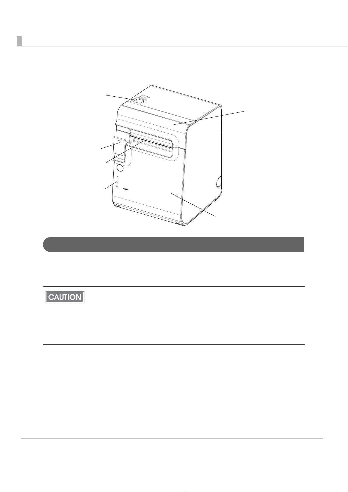
Part Names and Functions
Roll paper cover
Control panel
Cover open lever
Cutter cover
Powe r sw itch
Manual cutter
Power Switch
When DIP switch 1 is OFF (power switch: enabled), the power is turned ON/OFF. Press and
hold the switch for 1 second to turn the power on, and 3 seconds to turn the power off. After
turning the power on, approximately 30 seconds is required before printing is possible.
Before turning on the printer, be sure to check that the AC adapter is connected to the
power supply.
It is recommended that a power-off processing command be sent to the printer before
turning the power off. Doing so allows the latest maintenance counter value to be saved.
(Maintenance counter values are generally saved every two minutes.)
For more information about commands, see the "ESC/POS Application Programming
Guide".
18
Chapter 1 Product Overview
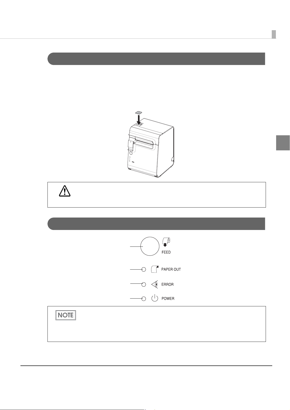
FEED button
Paper roll end(PAPER OUT) LED
Error(ERROR) LED
Power(POWER) LED
Power Switch Cover
Install the power switch cover that comes with the TM-L90-i onto the printer to prevent
inadvertent changing of the power switch, to prevent tampering, and to improve the appearance
of the printer.
To reset the printer when the power switch cover is installed, insert a long, thin object (such as
the end of a paper cl
ip) into the hole in the power switch cover and press the power switch.
1
If a failure occurs while the power switch cover is attached, immediately remove the
connector cover and remove the power cord.
WARNING
Otherwise, using the printer in this condition could cause a fire.
Control Panel
If the printer is installed horizontally, affix the control panel label for horizontal use. The
A FEED button is also located on the inside of the roll paper cover.
control panel for horizontal use is reversed top to bottom compared to the normal installation.
"Memory Switch Setting Mode" on page 128)
(See
19

LEDs
Paper roll end(PAPER OUT) LED
•Lights when there is no more roll paper or there is little remaining.
•Off when there is a sufficient amount of roll paper remaining.
•Flashes when a self-test printing standby state and macro execution standby state.
You can use the memory switch (Msw8-3) to set whether the PAPER LED flashes when
there is little roll paper remaining.
"Setting the Memory Switches" on page 96)
(See
Error(ERROR) LED
•Lights when the end of the roll paper is detected, and when printing has stopped (offline). If
this happens, replace the roll paper.
•Goes out during regular operation (online).
•Flashes when an error occurs. (For details about the flash codes, see "Error Status" on page 24.)
Power(POWER) LED (green)
•Lights when the power supply is on.
•Goes out when the power supply is turned off.
FEED button
When this button is pressed for receipt paper, the receipt is fed only 1line; for label paper, the
entire sheet is fed.
Holding this button down feeds the roll paper continuously.
20
Chapter 1 Product Overview
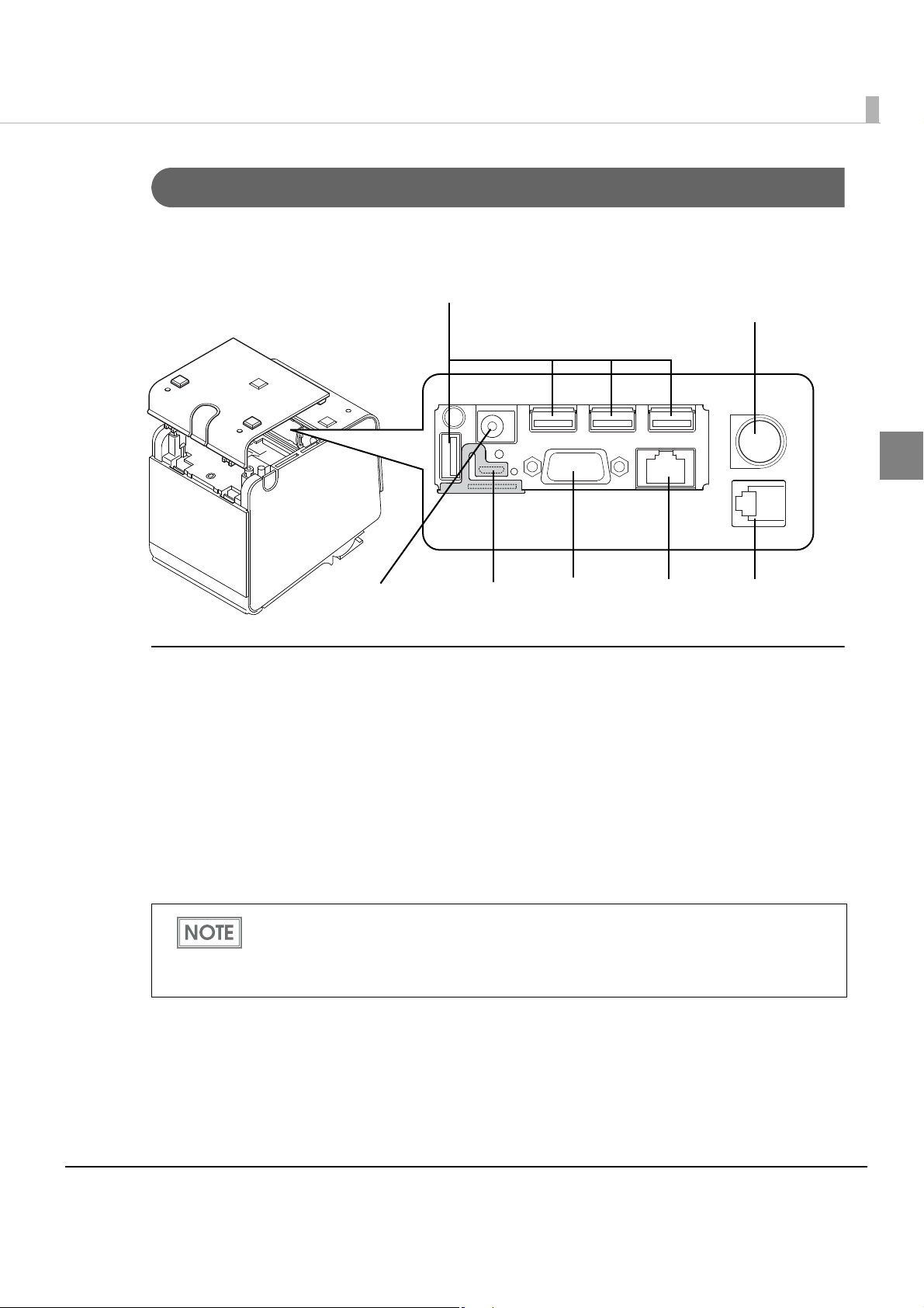
Power supply connector
(for DC 24V)
Ethernet
connector
Micro-USB
connector
Drawer kick-out
connector
*1
USB connectors
Power supply
connector for DC 5V
Connectors
When the connector cover is opened, you will see various connectors, a microSD card slot, and
push buttons.
1
Connector
•USB connector: Connects optional products.
•Power supply connector for DC 24V: Connects a power supply unit.
• Drawer kick-out connector: Connects a cash drawer or the optional buzzer unit.
•Ethernet connector: Connects the printer with a host computer.
•Micro-USB connector: Connect a micro USB (A-MicroB type) cable. This
cable is used only for configuration.
•Power supply connector for DC 5V: Connects a power supply unit.
*1: Analog RGB connector (Currently not available.)
For more information about connecting to a network, a power unit, a cache drawer, or other
external devices, see "Connecting the Printer to the System" on page 67, "Connecting the
Power Supply Unit" on page 65, "Connecting the Cash Drawer" on page 63, and
"Connecting to External Devices" on page 137.
21
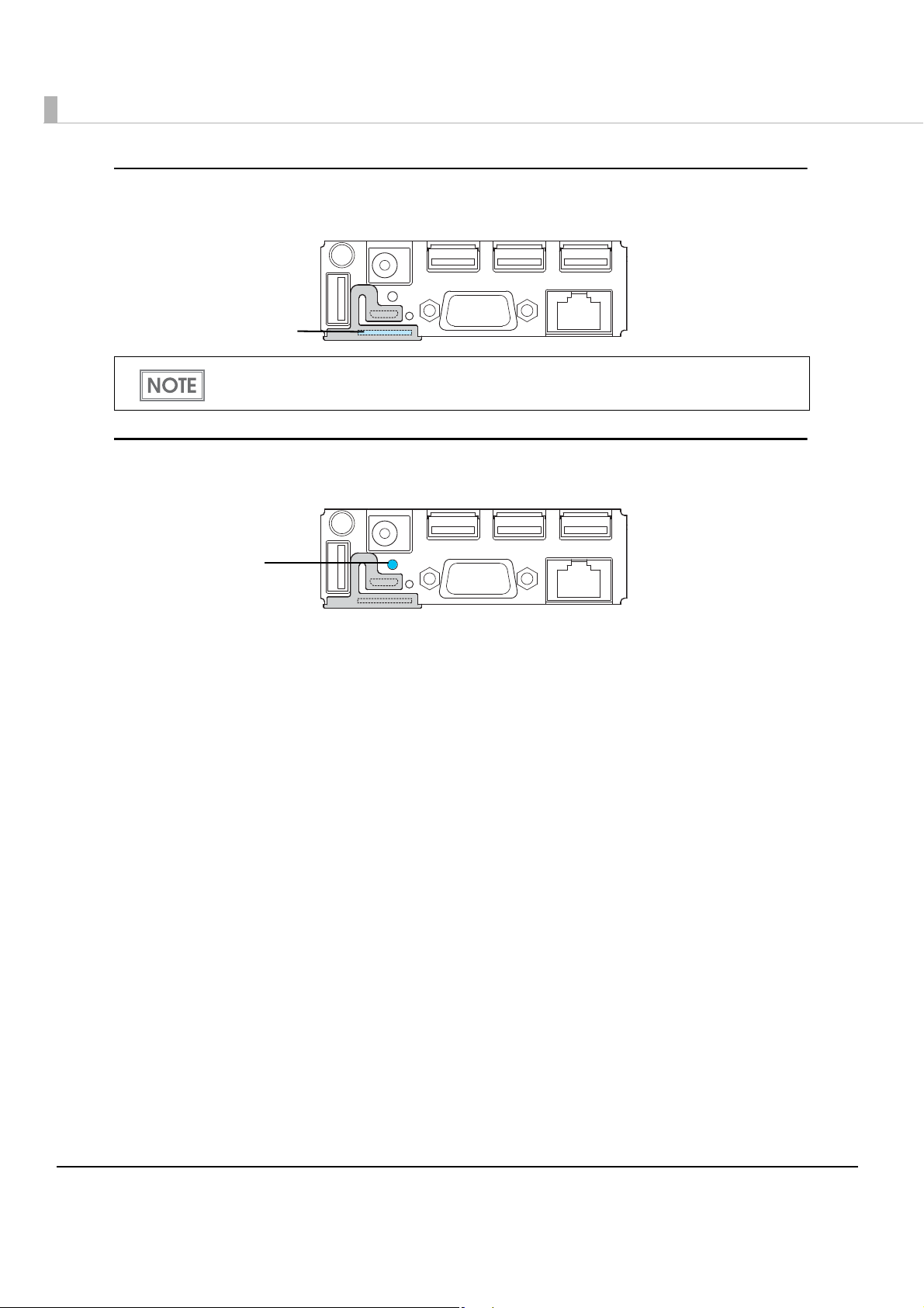
microSD Card Slot
microSD card slot
Push button
Insert a microSD card. When PHP functionality is enabled.
For more information about how to set up the PHP environment, see the "TM-i series PHP
Setup Manual".
Push Button
The push button on the lower rear of the printer prints a status sheet or initializes the printer.
The push button has below function:
•Status sheet printing:
Make sure the printer is turned on, press the push button for approximately 3 seconds. When
you release the button, a status sheet on
(See "Confirming with a status sheet" on page 78
•Initialization:
Make sure the printer is turned on, press the push button for approximately 10 seconds. When
you release the button, all setting will be initialized. (See
page 83.)
which network parameters are printed will be ejected.
.)
"Initializing the Network Setting" on
22

Chapter 1 Product Overview
Offline
The printer automatically goes offline under the following conditions:
•During power on (including resetting with the interface) until the printer is ready
•During the self-test
•While paper is fed using the Feed button
•When the cover is open
•When there is no paper and printing is stopped
(when the roll paper end detector indicates there is no paper)
• Macro execution standby
•When an error has occurred
1
23
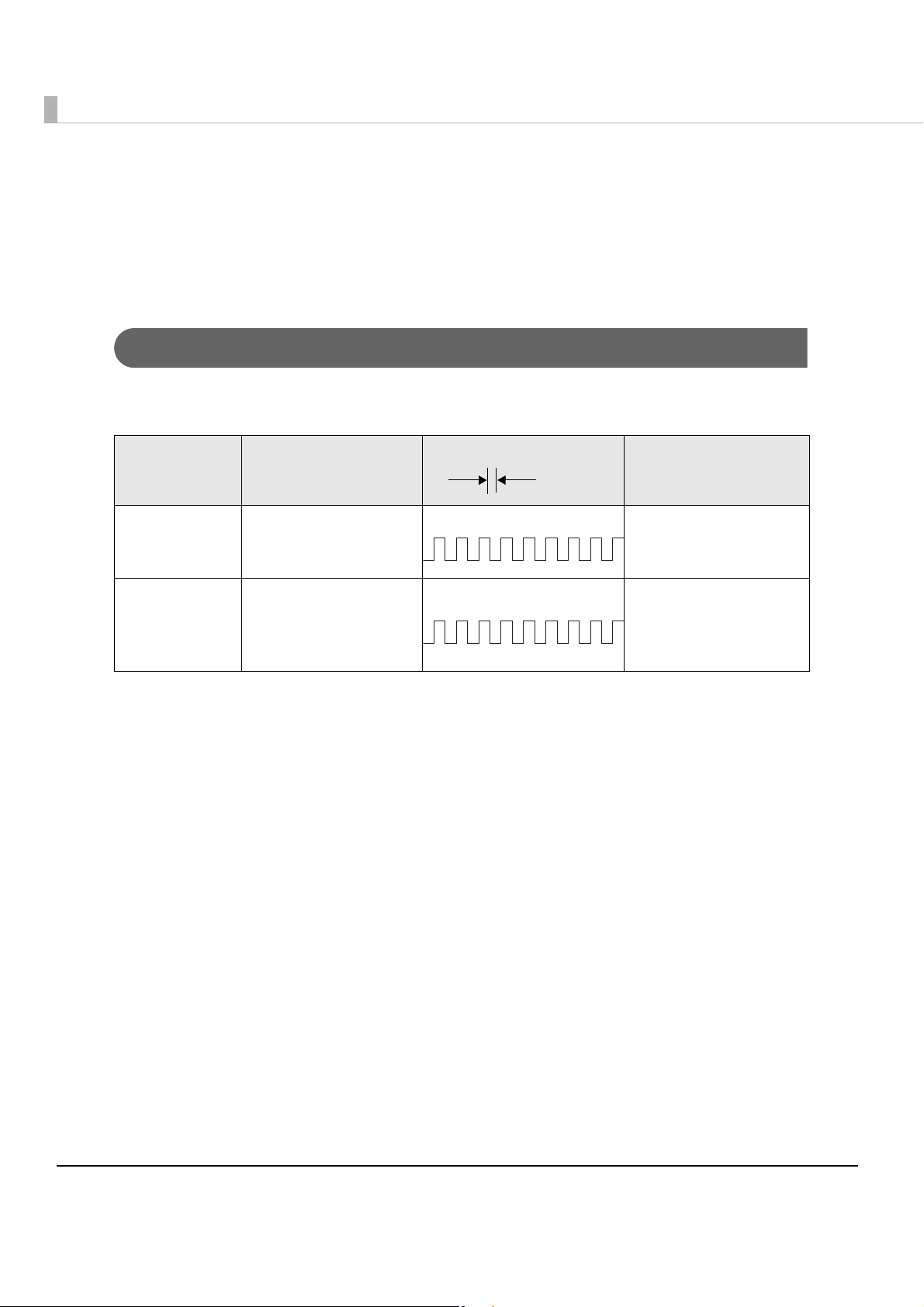
Error Status
Approx.
320 ms
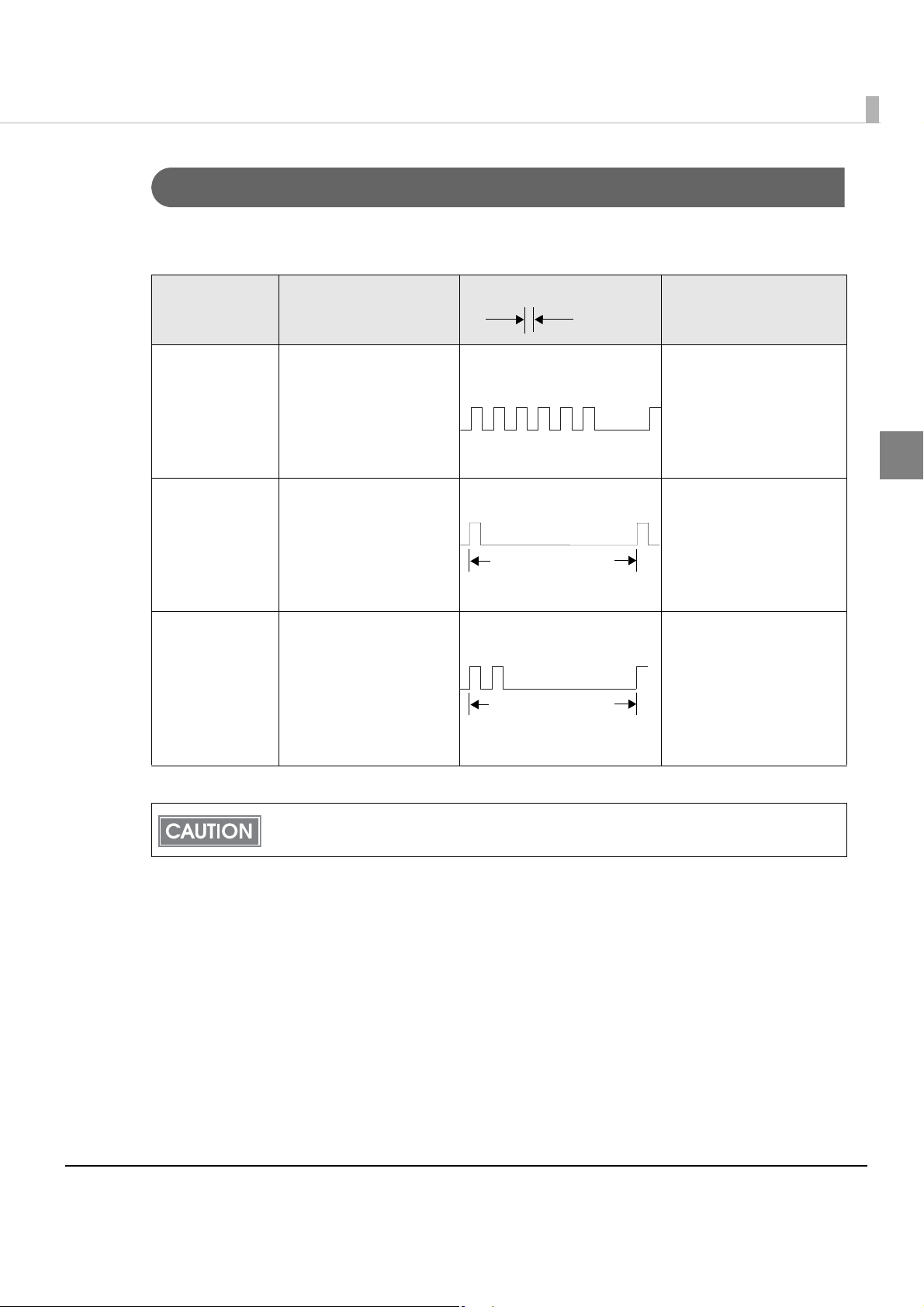
There are three possible error types: automatically recoverable errors, recoverable errors, and
unrecoverable errors. Check the error LED flash code.
When connection to external devices fails, check the status LEDs at the lower rear of the printer.
Automatically Recoverable Errors
Printing is no longer possible when automatically recoverable errors occur. They ca n be
recovered easily, as described below.
Error LED flash code
Error Error description
Recovery measure
Roll paper
cover open
error *
Print head
temperature
error
*: When memory switch 8-8 is set to OFF (roll paper cover open while printing: auto reset error)
The roll paper cover
was opened during
printing.
A high temperature
outside the head drive
operating range was
detected.
Recovers automatically
when the roll paper
cover is closed.
Recovers automatically
when the print head
cools.
24
Chapter 1 Product Overview
Approx.
320 ms
Approx. 5120 ms
Approx. 5120 ms
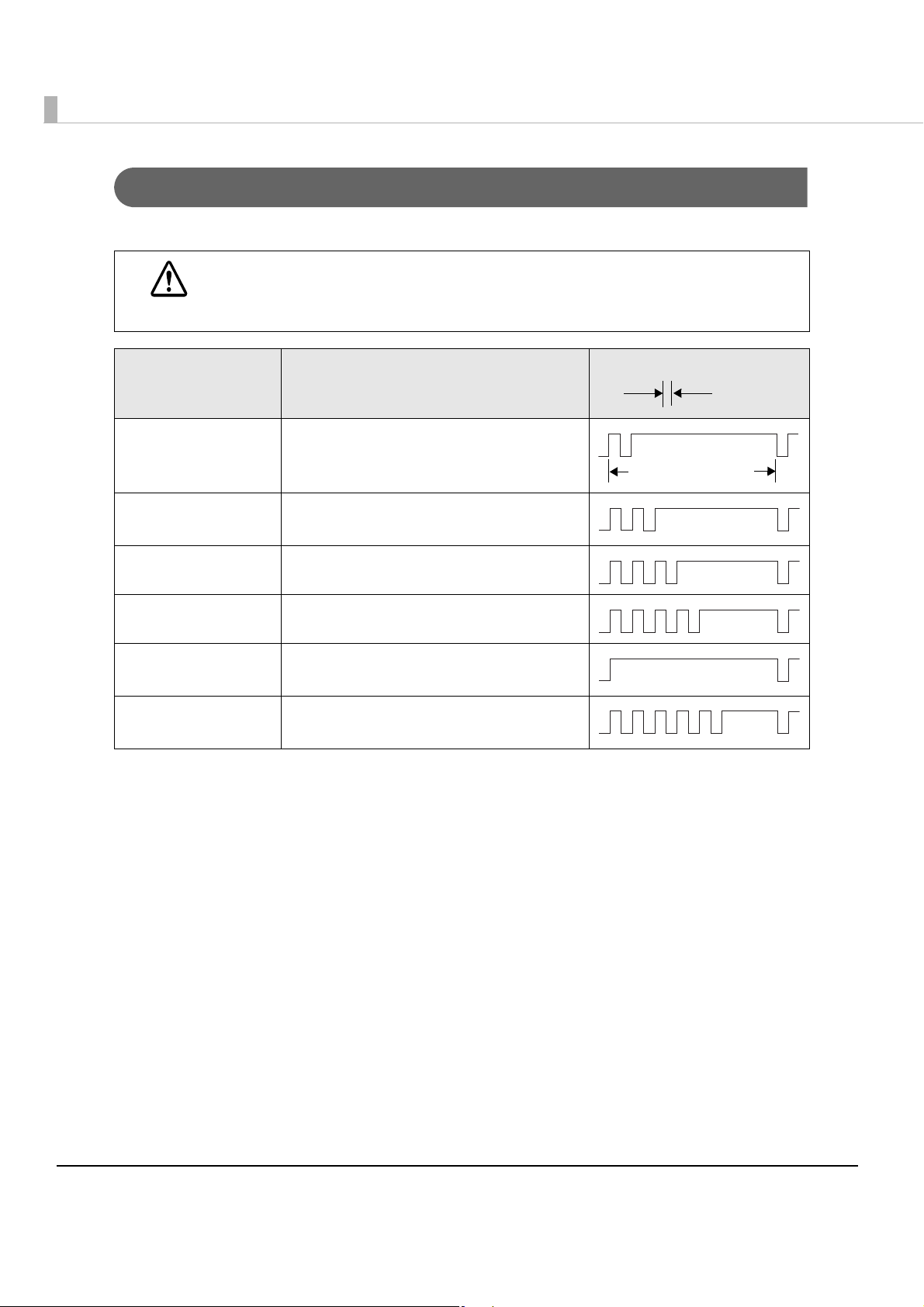
Recoverable Errors
Printing is no longer possible when recoverable errors occur. They c a n be recovered easily by
turning the power on again after eliminating the cause of the error.
Error LED flash code
Error Error description
Recovery measure
Roll paper
cover open
error *
Autocutter error The autocutter does not
Paper layout
error
*: When memory switch 8-8 is set to ON (roll paper cover open while printing: reset possible error)
The roll paper cover
was opened during
printing.
work correctly.
Cannot detect the
label or the black mark.
Close the roll paper
cover, and reset by
executing the error reset
command or turning the
power off and back on
again.
Remove the jammed
paper or foreign matter
in the printer, close the
roll paper cover, and
then turn the power on
to recover.
If the paper is jammed,
clear the jam, close the
roll paper cover, and
then execute the error
reset command or turn
the power off and back
on again.
1
The error reset command is enabled only when a reset possible error (not including auto
reset errors) occurs.
25
Unrecoverable Errors
Approx.
320 ms
Approx. 5120 ms
Printing is no longer possible when unrecoverable errors occur. The printer must be repaired.
Turn off the power immediately when unrecoverable errors occur.
CAUTION
Error LED flash code
Error Error description
Memory R/W error After R/W checking, the printer does not
work correctly.
High voltage error The power supply voltage is extremely
high.
Low voltage error The power supply voltage is extremely low.
CPU execution error The CPU is executing an incorrect address.
Internal circuit
connection error
Interface error An abnormal operation occurs in
Internal circuits are not connected
correctly.
interface.
26

Chapter 1 Product Overview
Status LED
Orange: Booting
Green: Operating normally
No Connection to External Devices
When connection to external devices is not possible, check the status LED at the back of the
printer.
When the status LED is lit in green
•Check whether the interface cable or the optional wireless LAN cable set is connected
correctly. (See
•Print the status sheet to check whether the network settings are correct. (See
Network Setting" on page 78
"Connecting to External Devices" on page 137.)
"Confirming
.)
When the status LED is lit in orange
When the status LED is off after turning on the printer or remains lit in orange even if 30 seconds
have passed after turning on the printer, the interface board needs repairing.
1
27
NV Memory (Non-Volatile Memory)
The printer's NV memory stores data even after the printer power is turned off. NV memory
contains the following memory areas for the user:
•NV graphics memory
• User NV memory
•Memory switches
•User-defined page
•Maintenance counter
•Paper layout settings
As a guide, NV memory rewriting should be 10 times or less a day when you program
applications.
NV Graphics Memory
Graphics, such as shop logos to be printed on receipts, can be stored.
Use the TM Flash Logo Setup Utility to register graphics.
User NV Memory
Yo u can store and read text data for multiple purposes, such as for storing a note including
customizing or maintenance information of the printer.
Memory Switches
Yo u can make a variety of printer settings, such as print density and printing speed.
For more information about memory switches, see
"Setting the Memory Switches" on page 96.
User-defined Page
Yo u can store character data in the user-defined page (character code table: page 255) so that you
can also print characters not resident in the printer.
28
Chapter 1 Product Overview
Maintenance Counter
With this function, printer information, such as the number of line feeds, the number of autocuts,
and printer operation time after the printer starts working, is automatically stored in NV
memory. Refer to the counter information when performing regular maintenance and replacing
s.
part
Paper layout settings
Paper layouts can be registered in this printer.
Registration is performed through panel operations or by executing commands.
If a paper layout is not registered, the printer will automatically determine the layout. The
results of this determination are temporarily saved in the printer. Whenever the printer is
turned on or the roll paper cover is closed, the paper is fed and the printer automatically
determines the paper layout.
(See "Auto paper determination" on page 95.)
1
29

Product Specifications
Printing method Thermal line printing
Cutting method Full cut
Roll paper 79.5 ± 0.5 mm (3.13 ± 0.02") (Paper width: 80 mm)
(with the paper roll spacer: 38 to 70mm)
Interfaces Ethernet (10Base-T/100Base-TX)
Wireless LAN (IEEE802.11b/g/n)*
USB2.0 (for optional products)
Micro-USB (for setting)
Buffers Receive buffer 4 KB/45 bytes (selectable using DIP switch 1-2)
User-defined buffer Downloaded bit image: Approximately 12KB
User-defined characters: Approximately 11KB
Macro buffer 2KB
1
NV graphics data
area
NV user memory 1 to 192KB
Page mode area 106KB
Barcode/two-dimensional
symbol/printing
Power supply EPSON AC ADAPTER, RA (Model: M266A)
2
Life*
Temperature/humidity Operating: 5 to 45°C {41 to 113°F}, 10 to 90% RH
Mechanism Label: 1,000,000 labels issued
Thermal head 150 million pulses
MTBF 360,000 hours
MCBF 70,000,000 lines
0 to 384KB
JAN 8 (EAN 8), JAN 13 (EAN 13), UPC-A, UPC-E, CODE 39, ITF,
CODABAR (NW-7), CODE 93, CODE 128, PDF417, QR CODE,
MaxiCode
Receipt(thickness type):10,000,000 lines
Receipt: 20,000,000 lines
150 km
Storage: -10 to 50°C {14 to 122°F}, 10 to 90% RH
Overall dimensions 140 × 148 × 203 mm {5.51 × 5.83 × 7.99"} (W × D × H)
Weight (mass) Approx. 1.9 kg {4.18 lb} (roll paper excluded)
*1: When the optional wireless LAN cable set (OT-WL01) is used.
*2: This will vary according to the type and model of paper used.
30

Chapter 1 Product Overview
Software Specifications
Print control ePOS-Print API, ePOS-Print XML
(XML Web service is used. No printer driver is required.)
Utility EPSON TMNet WebConfig
Network setting (Ethernet/Wireless LAN)
Web contents registration
ePOS-Print setting
Controllable printer WW Model Following printers with the UB-E02 or UB-R03 embed-
ded
TM-T88V
TM-T88IV*
TM-T70
TM-T20*
TM-T90
TM-L90*
TM-U220*
TM-P60II*
*: Firmware Ver.3 or later
1
TC Model Following printers with the UB-E02 or UB-R03 embed-
ded
TM-T88V
TM-T88IV
TM-T70
TM-T90
TM-L90*
TM-U220*
*: Firmware Ver.3 or later
SA Model Following printers with the UB-E02 or UB-R03 embed-
ded
TM-T88V
TM-T88IV
TM-T70
TM-T90
TM-L90*
TM-U220*
*: Firmware Ver.3 or later
31

Controllable printer SC Model Following printers with the UB-E02 or UB-R03 embed-
ded
TM-T88IV
TM-T70*
TM-L90*
TM-U220*
*: Firmware Ver.3 or later
KO Model Following printers with the UB-E02 or UB-R03 embed-
ded
TM-T88IV
TM-L90*
TM-U220*
*: Firmware Ver.3 or later
Number of
printers
20 printers at maximum
Intelligent Section Specifications
CPU Arm9/360MHz
ROM 256MB
RAM 256MB
30MB at maximum for Web contents
OS Linux Ver. 2.6.30
32

Chapter 1 Product Overview
Printing Specifications
Printing method Thermal line printing
Dot density 203 × 203 dpi
Printing direction Unidirectional with friction feed (Reverse feed is not
supported.)
Printing width
(when the paper width is 80mm)
Characters per line
(when the paper
width is 80mm)
Maximum print speed*
Line spacing 3.75 mm {0.15"}
dpi: dots per inch
*1: When printing with the default print density level at 24V and 25°C {77°F}.
Font A (12 × 24) 48
Font B (9 × 17) 57
1
To change the paper width, you must install the roll paper spacer and change the mem-
ory switch. (See
Since it is possible for some areas of the printer head and the auto cutter blades to
become worn through direct contact with the platen, it is not possible to change from a
narrow width to a wider width once operation has started.
"Customized value" on page 97)
72.0 mm (2.83"), 576 dots
Normal printing : 120 mm/s
High-speed printing : 150 mm/s
(Programmable by control command.)
1
33

Character Specifications
Number of characters Alphanumeric characters: 95
Extended graphics: 128 × 11 pages (including one space page)
International characters: 37 sets
Character structure Font A (default): 12 × 24
Font B: 9 × 17
Character size Font A Standard: 1.50 × 3.0 mm
Double-height: 1.50 × 6.0 mm
Double-width: 3.0 × 3.0 mm
Double-width, double-height: 3.0 × 6.0 mm
Font B Standard: 1.13 × 2.13 mm
Double-height: 1.13 × 4.25 mm
Double-width: 2.25 × 2.13 mm
Double-width, double-height: 2.25 × 4.25 mm
Note:
1. The actual print character may be smaller than the size shown in the table above, because the above size
includes spaces in the font.
2. Characters can be scaled up to 64 times as large as the standard size.
3. Character size not including the horizontal spacing in the standard scale is as follows:
Font A(12 x 24): 1.25(W) x 3.0(H) mm
Font B(9 x 17): 0.88(W) x 2.13(H) mm
34

Paper Specifications
Paper types Specified thermal paper
Receipt paper, continuous label paper
(without black mark)
Receipt paper (with black mark)
Die-cut label paper (without black mark)
Die-cut label paper (with black mark)
Form Roll paper
Size Paper width 83 mm {3.27"} maximum
79.5 ± 0.5 mm {3.13 ± 0.02"}
37.5 ± 0.5 mm {1.48 ± 0.02"} to 69.5 ± 0.5 mm {2.74 ± 0.02"}
Paper thickness Thick receipt paper: 145μm or less
Receipt paper: 62 to 75μm
Roll diameter Maximum 90 mm {3.54"}
Chapter 1 Product Overview
1
Roll paper spool Receipt (paper thickness is 75μm or less)
Roll width when taken up 80 + 0.5/-1.0 mm {3.15+0.02"/-0.04"}
Specified original paper type
Receipt TF60KS-E* (paper thickness: 75μm)
Inside: 12 mm {0.47"} or more
Outside: 18 mm {0.71"} or more
Other than the above
Inside: 25.4 mm {1.00"}
Outside: 31.4 mm {1.24"}
38 + 0.5/-1.0 mm {3.15+0.02"/-0.04"}
to 70 + 0.5/-1.0 mm {2.72+0.02"/-0.04"}
(Nippon Paper Industries Co., Ltd.)
TF11KS-ET (paper thickness: 145μm)
(Nippon Paper Industries Co., Ltd.)
TF50KS-E* (paper thickness: 65μm)
(Nippon Paper Industries Co., Ltd.)
PD150R* (paper thickness: 75μm) (Oji Paper Mfg. Co., Ltd.)
PD160R* (paper thickness: 75μm) (Oji Paper Mfg. Co., Ltd.)
P350* (paper thickness: 62μm)
(Kanzaki Specialty Paper (USA))
F5041* (paper thickness: 60μm)
(Mitsubishi HiTec Paper Flensburg GmbH (Germany))
KF50* (paper thickness: 62μm)
(KANZAN Spezialpapiere GmbH (Germany))
35

Die-cut label paper/
Continuous label paper
*: Paper for high-speed printing. Depending on the memory switch (customized values) settings, this paper can
allow printing at the printer's maximum printing speed (Level 9: approximately 150mm/s).
Paper must not be pasted to the paper roll spool.
If a manual cutter is used to cut paper with a thickness of 100μm or greater, the paper
will slide out of position easily. Take special care when cutting the paper.
Using roll paper with an inside diameter of 25.4 mm {1"} or less may decrease the detec-
tion accuracy of the roll paper near-end sensor.
To ensure high printing quality and performance, it is recommended that you make
changes to the printing density settings ("Customized value" on page 97
the roll paper that is used.
HD-75* (Nippon Paper Industries Co., Ltd.)
HW76B* (Nippon Paper Industries Co., Ltd.)
HW76C* (Nippon Paper Industries Co., Ltd.
KL470* (NAKAGAWA MFG(USA).Inc.)
KL80GT* (NAKAGAWA MFG (Germany). GmbH.)
150HA* (Ricoh Co., Ltd.)
) according to
36

Chapter 1 Product Overview
Paper feed direction
[2]
[1]
Units: mmBack(non-printing side)
4 to 7.5
40 to 300
15 or
more
Preprintable area
Receipt Paper/Continuous Label Roll Paper
When using receipt paper/continuous label roll paper , be sure to use paper that meets the
following requirements.
Requirements for Black Mark
When using receipt paper/continuous label roll paper with black marks, be sure to use paper
that meets the following requirements.
Paper without intervals between labels, such as continuous label paper, paper with
perforated lines between labels, and paper with slits between labels, can also be used
under the same requirements.
• Black mark portions must be printed on the back of the paper (non-printing side).
•The reflecting rates of black mark portions [1] and non black mark portions [2] must meet the
combinations shown in t
(Reflecting rates are measured by the Macbeth PCM-II (Filter D) meter, using the back of the
paper.)
he table below :
1
Reflecting rate of black mark portion [1]
Reflecting rate of the portion where
the black mark does not exist [2]
17%
less
90%
more
16%
less
85%
more
15%
less
80%
more
14%
less
75%
more
13%
less
70%
more
37

Requirements for the Edge Cutoff of Continuous Label Roll Paper
Paper feed direction
[a]3.5 mm {0.14"}
or more
Face stock (printing side)
[b]0.3 mm {0.12"}
or more
To preve nt the print head from sticking to the adhesive agent, be sure to use continuous label
paper that edge cutoff(“Edge cutoff” is a method of cutting and removing the edge of the label in
advance so that the label can be peeled off easily from the backing paper.) has been done.
•When performing a full-cut, for the cutoff edge (a): 3.5 mm {0.14"} or more is n
ot necessary;
however, it is recommended that cutoff edges with approximately 2 mm {0.79"} width be
provided for both edges so that the label can be peeled off easily from the backing paper.
•When using a label with 80 mm {3.15"} paper width, the cutoff edge (b) is not necessary;
however, it is recommended that cutoff edges with approximately 2 mm {0.79"} wid
th be
provided for both edges so that the label can be peeled off easily from the backing paper.
•In consideration of the cutoff edges, allow the left and right margins of 2.8 mm or more
outside the printable area.
Requirements for thickness and adhesive agent of continuous label roll paper
Requirements if an original paper other than the specified original paper is used are as follows:
•Total amount of thickness of the thermal paper and backing paper: 145 μm or less (without
adhesive agent).
•Adhesive agent: Acrylic emulsion
38

Chapter 1 Product Overview
Thermal paper (label)
Thickness: 70 to 92μm
Adhesive agent (acrylic emulsion)
Thickness: 9 to 21μm
Adhesive agent (acrylic emulsion)
Thickness: 41 to 71μm
Label + Backing paper:
Transparency rate: 18% or less
Backing paper:
Transparency rate: 47% or more
Die-cut Label
Requirements for the thickness of the die-cut label paper, peeling strength against backing paper,
and the adhesive agent that can be used with the printer are shown in the figure below:
1) Paper Thickness, peeling strength, and adhesive agent
2) Requirements for transparency rate of die-cut label paper
1
39

Transparency rates are measured by the Macbeth TD-904 (with a filter for infrared) pho-
Units: mmFace (printed side)
Detection hole
Corner R2 or less
Corner R0.5 or less
0.5±0.3
0.5±0.3
8.0±0.1
6±0.5
1.75±0.5
5.0±0.5
tometer. The transparency rates are calculated as follows:
Use
Density = Log10 (Amount of irradiation / Amount of transparency)
Then,
Transparency rate (%) = (Amount of transparency / Amount of irradiation) x 100
If the transparency rates are out of the specified range (label + backing paper: 18% or
less, backing paper: 47% or more), the printer detects a layout error. However, paper
identified with a layout error may be used when the detection hole is prepared as follows.
The position to detect the label may be shifted by approximately 0.5 mm {0.02"}.
40

Chapter 1 Product Overview
Units: mmFace stock (printing face)
Paper feed
direction
2.8 or more 2.8 or more
Corner R2 or less
37.5±0.5 to 69.5±0.5 or 79.5±0.5
1.5 or more
1.5 or more
1.75±0.5 1.75±0.5
L2=3 to 10
L3
L4
(Label length: 25.4 ~ 101.6)
(Printable area)
Label interval L1:
(Label length +
L2)
Cutting position
Requirements for die-cut label size (without black marks)
Die-cut labels (without black marks) must satisfy the following requirements.
1
•Be sure to set the cutting position (L4) to 1.5 mm {0.059"} or more from the label edges at the
top and the bottom.
•Be sure that the distance from the cutting position to the print starting position (=L3-L4) is 2.75
mm {0.108"} or more. And the minimum label length must be 25.4 mm {1"}.
41

Requirements for die-cut label size (with black marks)
If die-cut label with black marks is used, there are two reflective rate requirements, depending
on the size and position of black marks. Be sure to use label paper that meets either black mark
position requirement I or II as follows.
Requirements for Black Mark Position I (when the black mark overlaps the adjacent label)
• Black mark portions must be printed on the back of the paper (non-printing side).
•The length of the black mark must cover the space between labels (backing paper between
labels) completely (overlapping labels by 0 to 1 mm).
•The reflective rates of the black mark portions [1] and label portions [2] must meet the
combinations shown in the table below (the reflective rate is measured using the back of the
paper, the non-printing side):
Reflecting rate for black mark portion [1]
Reflecting rate for label portion [2]
17%
less
90%
more
16%
less
85%
more
15%
less
80%
more
14%
less
75%
more
13%
less
70%
more
42

Chapter 1 Product Overview
Units: mmBack (non-printing side)
Paper feed direction
Preprintable area
15.0 or more
0.5±0.5
[2]
[1]
Cutting position
5.0±0.5
0.5±0.5
Reflective rates are measured by the Macbeth PCM-II (Filter D) meter.
1
Requirements for Black Mark Position II (when the black mark is between two labels)
• Black mark portions must be printed on the back of paper (non-printing side).
• If label paper meets Black Mark Position Requirement I, it is not necessary to consider Black
Mark Position Requirement II.
•The reflective rates of each portion [1], [2], and [3] must meet the combinations shown in the
table below (the reflective rate is measu
Reflective rate of black mark portion[1]
Reflective rate of the portion where the
black mark does not exist [2][3]
red using the back of the paper, the non-printing side):
17%
less
90%
more
16%
less
85%
more
15%
less
80%
more
14%
less
75%
more
13%
less
70%
more
43

Reflective rates are measured by the Macbeth PCM-II (Filter D) meter.
Units: mmBack (non-printing side)
Paper feed direction
Preprintable area
15.0 or more
[2]
[1]
5.0±0.54 to 5.5
[3]
44

Chapter 1 Product Overview
(2.65 mm)
(4.85 mm)
72 mm
0.125 mm
79.5 0.5 mm
576 dot
Printable Area
Receipt Paper/Continuous Label Roll Paper
The printable area may be out of alignment by 2 mm {0.08"} maximum (left or right), due to the
paper position or tolerance of parts. Please set by referring to the following.
Paper width (mm) 80 70 65 60 58 50 45 38
Printable area (mm) 72 64 59 54 52 44 39 32
Left margin (mm) 2.65 2.65 2.65 2.65 2.65 2.65 2.65 2.65
Right margin (mm) 4.85 2.85 2.85 2.85 2.85 2.85 2.85 2.85
Total number of dots 576 512 472 432 416 352 312 256
Example: 80mm paper width
1
Example: 58mm paper width
(2.65 mm)
57.5 0.5 mm
0.125 mm
52 mm
(2.85 mm)
416 dot
45

Die-cut Label
[Units: mm]
Liner width
Label (face stock) width
Printable area
1.5 or more
1.5 or more
2.8 or more2.8 or more
Make a margin of 2.8 mm {0.11"} or more from the label edges on both left and right sides and
also a margin of 1.5 mm {0.059"} or more from the label edges on top and bottom of the printable
area of the label (face stock).
Liner width (mm) 80 70 60 50 45 38
Label width (mm) 76 66 56 46 41 34
Printable area (mm) 70 60 50 40 35 28
Left margin (mm) 2.9 2.9 2.9 2.9 2.9 2.9
Right margin (mm) 3.1 3.1 3.1 3.1 3.1 3.1
Total number of dots 560 480 400 320 280 224
46

Printing and Cutting Positions
Autocutter blade position
Approx. 29
Approx. 14
Manual-cutter position
Center of the print dotline
Paper feed direction
Chapter 1 Product Overview
1
The values above may vary slightly as a result of paper slack or variations in the paper.
Take this into account when setting the cutting position of the autocutter.
Partial cuts (a portion of the left edge remains) can be made only on receipt paper with-
out black marks or full-surface label paper without black marks.
When making a partial cut (leaving a portion of the left edge), do not perform a back
feed.
Lengths of receipts/labels
To preve nt paper jams or to make it easier to remove printed receipts/labels, the following
lengths are recommended for printing receipts/labels.
Use condition Recommended issuing length
Horizontal installation (full cut) 37.5 mm or more
Horizontal installation (partial cut)
25.4 mm or more
Vertical installation
47

Electrical Characteristics
42 columns
Supply voltage DC 24V ± 7%
Current consumption
(at 24V, 25°C, normal
print density)
* When the supply current from the USB connectors is
•less than 600mA: Maximum 1.0A
•more than 600mA: Maximum 2.5A
Standby Mean: Approximately 0.1A
Maximum 1A for drawer kick-out driving.
Operating DC 24V Mean: Approximately 1.7A
DC 5V*: Maximum 1.0A/2.5A
Note: When print ratio is
approximately 18%
Continuous printing for 100
lines (repeating 20H-7FH)
Font A
42 columns
ASCII character
ABCDE
BCDE
6789
67890
48

Environmental Conditions
Relative humidity
Operating environment
range
90
65
10
5344045
Ambient temperature
[%RH]
[°C]
Chapter 1 Product Overview
Temperature/
Humidity
Acoustic noise (operating) Approximately 53 dB (bystander position)
Operating 5 to 45°C {41 to 113°F}, 10 to 90% RH
(See the operating temperature and humidity range below.)
Storage
(Factory packing)
-10 to 50°C {14 to 122°F}, 10 to 90% RH (except for paper)
Note:
The values above are measured in the Epson evaluation
condition.
Acoustic noise differs depending on the paper used, printing
contents, and the setting values, such as print speed or print
density.
1
49

External Dimensions and Mass
•Height: Approximately 203 mm {7.99"}
•Width: Approximately 140 mm {5.51"}
•Depth: Approximately 148 mm {5.83"}
• Mass: Approximately 1.9 kg {4.18 lb} (except for roll paper)
TM-L90-i Dedicated AC Adapter
Input conditions Input voltage: AC 100V to 240V
Frequency: 50/60 Hz
Input current (rating): 1.3A
Output conditions Output voltage (rating): DC 24V ± 5%
Output current (rating): 2.1A
50

Chapter 1 Product Overview
Option Specifications
Wireless LAN Cable Set (OT-WL01)
Wireless module ELPAP07: 802. 11b/g/n wireless LAN Module (EPSON)
Standard IEEE802.11b/g/n (Wi-Fi certificated)
SSID 1 to 32 one-byte alphabet and numbers
Connection mode Ad hoc mode, Infrastructure mode
Authentic method, Encryption algorithm Open+WEP, Shared+WEP, WPA-PSK+TKIP, WPA-PSK+AES,
WPA2-PSK+AES, WEP64, WEP128, TKIP, AES
Power voltage DC 4.5V to 5.5V
Current consumption 300mA at maximum
1
Frequency range 2.4 GHz band
Potential interference range 40 m
Overall dimensions Wireless LAN unit: Approx. 24 × 51 × 10 (W × D × H)
USB extension cable: 1 m (length)
51

52

Setup
2. Changing the Paper Width (page 57)
7. Connecting the Printer to the System (page 67)
5. Connecting the Cash Drawer (page 63)
4. Setting the DIP Switches (page 62)
6. Connecting the Power Supply Unit (page 65)
1. Installing the Printer (page 55)
3. Adjusting the position of the roll paper near end detector (page 59)
8. Network Setting (page 72)
9. Establishment of ePOS-Print System (page 84)
This chapter describes setup and installation of the product and peripherals, and setup for
ePOS-Print.
Flow of Setup
This chapter consists of the following sections along with the setup flow of the product and
peripherals.
In this setup flow, necessary items are in a frame with a solid line. Optional items are
explained in an frame with a dotted line.
Chapter 2 Setup
2
53

54
13. Setting the Memory Switches (page 96)
14. Handling Cables (page 101)
12. Paper Layout Settings (page 92)
10. Setting for Connected Devices (page 87)
11. Registering Web Pages (page 89)

Chapter 2 Setup
Horizontal position
Ver t i c a l posit i o n
Installing the Printer
Although this printer is normally installed and used vertically (with the paper discharged to the
front), it can also be installed and used horizontally (with the paper discharged to the top).
Do not place the printer in dusty locations.
Do not knock or strike the printer. This may cause defective print.
Do not catch cables or place foreign matter under the printer.
If you install the printer horizontally, affix the control panel labels for horizontal use.
(see "Control panel label for horizontal use" on page 56)
In addition, if the auto cutter is used to make full cuts with the printer installed horizontally, the
included paper discharge guide must also be installed.
"Installing the paper discharge guide" on page 56)
(see
2
55

Control panel label for horizontal use
When using the printer in the horizontal position, affix the control panel label for horizontal use
as shown in the figure.
Installing the paper discharge guide
If the auto cutter is used to make full cuts with the printer installed horizontally, the paper
discharge guide must be installed as shown in the figure.
This will prevent the cut paper from falling into the paper path, which could cause double cuts
and paper jams.
If roll paper with an inner diameter smaller than 25.4mm and an outer diameter smaller than
31.4mm is used, paper jams are likely to occur. Therefore, do not install the paper
discharge guide.
56

Chapter 2 Setup
Edge
Groove
Changing the Paper Width
This printer is shipped from the factory with the roll paper width set to 80mm. To use roll paper
with a width of 38mm to 70mm, install a roll paper spacer using the following procedure.
Since it is possible for some areas of the printer head and the auto cutter blades to
become worn through direct contact with the platen, it is not possible to change from a
narrow width to a wider width once operation has started.
To change the paper width, use the memory switch to change the paper width settings.
To use roll paper with a width of 61mm to 70mm, fold the tabs in two
1
locations on the roll paper spacer.
Even if the tabs are folded, you can still use roll paper with a width of 38mm to 60mm.
Open the roll paper cover.
2
Insert the roll paper spacers through the grooves on the inside edges of
3
the printer, and downward.
2
57

Press the spacers firmly into the spindle at the bottom surface.
Spindle
screw
4
Make sure the roll paper spacers slide smoothly to the left and right.
5
Move the roll paper spacers to the left and right, align them with the
6
position of the roll paper to be used, and fix them into place with the
included screws.
Set the roll paper spacers with an additional margin of 0.5mm over the maximum value for
the width of the roll paper. Use a ruler if necessary.
58

Chapter 2 Setup
Adjusting the position of the roll paper near end detector
The position of the roll paper near end detector must be adjusted in the following situations.
•When the installation direction of the printer is changed (from vertical to horizontal, or vice-
versa)
•When changing the remaining amount of roll paper detected by the near end detector
Since the center of the roll paper has a slightly different shape than the specifications
indicate, the near end cannot be detected precisely.
In order for the near end detector to correctly detect the amount of roll paper remaining,
use receipt paper with an inner diameter of 12mm or greater and an outer diameter of
18mm or greater; all other roll paper should have an inner diameter of 25.4mm and an
outer diameter of 31.4mm.
When shipped from the factory, this printer is adjusted for use in the vertical position.
2
59

Adjustment procedure
Horizontal position
Ver t i c a l posi t i o n
Adjustment
screw
Knob
Detection
lever
Adjustment
screw
Knob
Detection
lever
Open the roll paper cover.
1
Use a coin or similar object to loosen the adjustment screw on the
2
detector.
Push the detection lever all the way to the rear window, and then turn
3
the knob until the detection lever is set in the position shown in the figure
below.
Changing from horizontal to vertical : Turn the knob towards you.
Changing from vertical to horizontal : Turn the knob away from you.
60

Chapter 2 Setup
Horizontal position
Ver t i c a l posi t i o n
Knob
Knob
Move the knob forward/back or up/down, and align the line in the knob
4
with the position shown below.
Roll paper diameter for near end
detection
41 mm Top Left
36 mm Under (Default) Right
Vertical position Horizontal position
2
Tighten the adjustment screw on the detector.
5
Press the detection lever with your finger to check if it moves smoothly.
6
61

Setting the DIP Switches
Yo u can use the DIP switches to enable/disable the power switch. The initial setting is "Enabled".
Setting Procedure
Follow the steps below to change the DIP switch settings.
Be sure to turn the power off before setting the DIP switch.
Make sure the power supply for the printer is turned off.
1
Open the roll paper cover.
2
Remove the DIP switch cover.
3
62
Set the DIP switch 1, using the tip of a tool, such as a small screwdriver.
4
ON : Power switch is Disable
OFF : Power switch is Enable
Do not make any change to DIP switches other than DIP switch 1.
Install the DIP switch cover, and close the roll paper cover.
5

Connecting the Cash Drawer
DK
24V
Drawer kick-out connector
When using a cash drawer, connect the cash drawer.
Use the cash drawer handled by EPSON or your dealer.
Connecting the Drawer Kick-out Cable
Specifications of drawers differ depending on makers or models. When you use a
drawer other than specified, make sure its specification meets the following
WARNING
conditions.
Otherwise, devices may be damaged.
The load, such as a drawer kick-out solenoid, must be connected between pins 4 and
2 or pins 4 and 5 of the drawer kick-out connector.
When the drawer open/close signal is used, a switch must be provided between
drawer kick-out connector pins 3 and 6.
The resistance of the load, such as a drawer kick-out solenoid, must be 24
or the input current must be 1A or less.
Be sure to use the 24V power output on drawer-kick out connector pin 4 for driving the
equipment.
Use a shield cable for the drawer connector cable.
Two driver transistors cannot be energized simultaneously.
Leave intervals longer than 4 times the drawer driving pulse when sending it
continuously.
Be sure to use the printer power supply (connector pin 4) for the drawer power
source.
Do not insert a telephone line into the drawer kick-out connector.
Doing so may damage the telephone line or printer.
Chapter 2 Setup
or more
2
Connect the connector of the drawer kick-out cable to the printer.
63

Drawer Connection Circuitry
F. G
+24V
With shielded
Drawer kick-out connector
Printer side
User side [Drawer kick-out side]
Drawer open/close switch
Drawer kick-out solenoid
Control device
1
2
3
4
5
6
64

Connecting the Power Supply Unit
Use the TM-L90-i dedicated AC adapter and the AC cable included with the product as the
power supply unit.
Be sure to use the included AC adapter as the power supply unit.
Using a nonstandard power supply can result in electric shock and fire.
WARNING
Should a fault ever occur in the included AC adapter, immediately turn off the
power to the printer and unplug the power supply cable from the wall socket.
Be sure to unplug the power supply unit’s cable from the wall socket whenever
connecting or disconnecting the power supply unit to the printer.
Failure to do so may result in damage to the power supply unit or the printer.
Make sure the wall socket power supply satisfies the rated voltage requirements
of the power supply unit. Never insert the power supply cable plug into a socket
that does not meet the rated voltage requirements of the power supply unit.
Doing so may result in damage to both the power supply and the printer.
Chapter 2 Setup
For more information about how to handle cables, see
Connecting the Power Supply Unit
Make sure the power supply for the printer is turned off.
1
Remove the connector cover.
2
"Handling Cables" on page 101.
2
65

Connect the AC adapter and AC cable.
AC cable
TM-T90-i dedicated AC adapter
DC 24V
DC 5V
3
66

Connecting the Printer to the System
TM-L90-i
Serial cable
Modular cable
Cash drawer
10BASE-T/100BASE-TX
DM-D
The printer uses a modular connector specifically designed for the cash drawer. Do not
connect the connector to an ordinary telephone line.
For more information about how to handle cables, see
For Ethernet Interface
Connect the printer to a network by a LAN cable via a hub.
Ethernet interface connection diagram
"Handling Cables" on page 101.
Chapter 2 Setup
2
67

Connecting the Ethernet interface cable
Ethernet connector
When LAN cables are installed outdoors, make sure devices without proper surge
protection are cushioned by being connected through devices that do have surge
CAUTION
Connect a 10BASE-T/100BASE-TX cable to the 10BASE-T/100BASE-TX LAN connector by
pressing firmly until the connector clicks into place.
protection.
Otherwise, the devices can be damaged by lightning.
Never attempt to connect the customer display cable, drawer kick-out cable, or a
standard telephone line cable to the 10BASE-T/100BASE-TX LAN connector.
68

Chapter 2 Setup
TM-L90-i
Modular cable
Cash drawer
Access point
For Wireless LAN Interface
The optional wireless LAN cable set (OT-W01) enables you to use the printer with a wireless
LAN connection.
Be sure not to connect a LAN cable when you use the wireless LAN cable set.
This printer cannot be used with the LAN connection and wireless LAN connection at the
same time. When the printer is set and installed for both of them, only the LAN connection
works.
Wireless LAN interface connection diagram
Connecting the wireless LAN cable set
Check whether the following items are included. If any item is damaged, contact your dealer.
•Wireless LAN unit
•USB extension cable
•Affixing tape (1 pair, 2 p ieces)
•Rubber cover
• User’s manual
2
To connect the wireless LAN unit to the printer, you can connect directly or use the USB
extension cable.
If conn
communication, use the included USB extension cable.
ecting the wireless LAN unit directly causes interference with other cables or bad
69

Connecting the unit directly with the printer
USB connector
Install the wireless LAN unit to a USB connector of the printer.
Using the USB extension cable
Attach the included rubber cover to the connector of the USB extension
1
cable into which the wireless LAN unit will be inserted, to prevent the unit
from coming off.
Insert the wireless LAN unit into the connector of the cable.
2
Adjust the position of the rubber cover so that the description on the label on the back side
of the wireless LAN unit is not covered.
70

Connect the USB extension cable to the USB connector of the printer.
Wireless LAN indicator
3
If you want to fix the wireless LAN unit, cut the included affixing tape to fit and put on the
unit, and fix the unit in a place with good communication.
Chapter 2 Setup
Wireless LAN indicator
The position of the wireless LAN indicator is shown in the illustration below.
Wireless LAN indicator
(Green)
Off
Flashing This wireless LAN unit is connected to the printer and is in operation.
Flashing rapidly
The wireless LAN unit is not connected to the printer. Or the printer
power is OFF.
This wireless LAN unit is connected to the printer and is in operation.
This unit is communicating on a network.
Status
2
71

Network Setting
5
6
7
8
There are two methods for network settings.
•EPSON TMNet WebC o nfig: Set from the computer's web browser
•EpsonNet Config: Set from EpsonNet Config, which is first installed on the computer.
The initial value for the IP address is the value acquired via DHCP. If automated acquisition of
an IP address via DHCP fails, set "192.168.192.168" as the IP address. When
on, the IP address is acquired automatically and then printed. The setting method using EPSON
TMNet WebC o nfig is explained here. For more information about how to use EpsonNet Config,
refer to the EpsonNet Config Operations Guide.
For more information about how to use EPSON TMNet WebConfig, see "EPSON TMNet
WebConfig" on page 105
With either connection, wired LAN or wireless LAN, network setting for both the wired
LAN and wireless LAN is possible.
.
Wired LAN Setting
Follow the steps below to set for wired LAN by using EPSON TMNet WebConfig.
the printer is turned
72

Chapter 2 Setup
Connect a PC for setting to the network.
1
Connect the TM-L90-i printer to the network, and turn it on.
2
Print a status sheet.
3
For how to print a status sheet, see "Confirming with a status sheet" on page 78.
Set the PC for setting as the same as the setting printed on the status
4
sheet.
Start up the web browser on the PC for setting, and enter the printer’s IP
5
address printed on the status sheet in the address bar as shown below.
http://xxx.xxx.xxx.xxx/PrinterConfigurationPage/
EPSON TMNet WebConfig starts.
Select [Configuration], [Wired], and then [TCP/IP].
6
The [TCP/IP Setting (Wired)] screen appears.
2
Configure the printer’s network setting.
7
For details, see "TCP/IP Setting (Wired)" on page 113.
Click [Submit].
8
73

Wireless LAN Setting
5
6
7
8
9
Follow the steps below to set for wireless LAN (when the optional wireless LAN cable set,
OT-WL01, is used) by using EPSON TMNet WebCo nfig.
This printer cannot be used with the LAN connection and wireless LAN connection at the
same time. When the printer is set and installed for both of them, only the LAN connection
works.
74
1
2
3
4
5
Connect a PC for setting to the network.
Connect the TM-L90-i printer to the network, and turn it on.
Print a status sheet.
For how to print a status sheet, see "Confirming with a status sheet" on page 78.
Set the PC for setting as the same as the setting printed on the status
sheet.
Start up the web browser on the PC for setting, and enter the printer’s IP
address printed on the status sheet in the address bar as shown below.
http://xxx.xxx.xxx.xxx/PrinterConfigurationPage/
EPSON TMNet WebConfig starts.

Select [Configuration], [Wireless], and then [TCP/IP].
6
The [TCP/IP Setting (Wireless)] screen appears.
Configure the printer’s network setting.
7
For details, see "TCP/IP Setting (Wireless)" on page 116.
Click [Submit].
8
Select [Configuration], and then [Wireless].
9
The [Wireless Setting] screen appears.
Configure security settings for the network.
10
For details, see "Security setting" on page 76 and "Wireless Setting" on page 114.
Click [Submit].
11
Chapter 2 Setup
2
75

Security setting
Set the following items depending on the network mode.
Item Description
Network Mode Set the communication mode (Infrastructure/Ad-Hoc).
SSID Same value as that for access point. 32 alphanumeric
characters at maximum.
Ad-Hoc Channel Set when [Ad-Hoc] is selected for [Network Mode].
Selectable from 1 to 11.
Communication Standard Set the communication standard.
Authentication Method Set the authentication algorithm.
Security Mode Set the encryption algorithm.
Default WEP Key Set the WEP key to use.
WEP Key 1 to 4 Set character strings for WEP keys when using WEP for
security setting.
WPA/WPA2 Pre-Shared Key Set a character string (8 to 63 ASCII characters) for
[WPA/WPA2 Pre-Shared Key] when using WPA/WPA2 for
security setting.
76

Chapter 2 Setup
Initially, Authentication Method is set to Open System and Security Mode is set to None.
To ensure security, be sure to change the set-tings before use.
The following restrictions apply to the characters that can be specified for SSID, WEP
keys, and WPA/WPA2 pre-shared keys.
ASCII characters, excluding spaces
2
77

Confirming Network Setting
Push button
Yo u can confirm the network setting with a status sheet or EPSON TMNet WebCo nfig.
Confirming with a status sheet
Make sure the printer is turned on, press the push button at the interface part for approximately
3 seconds. When you release the button, a status sheet on which network parameters are printed
will be ejected.
With the status sheet, you can check the network settings.
Use a sharp-pointed object to press
If you keep pressing the button for more than 10 seconds, the network settings are
initialized.
Information on a status sheet
the push button.
78

Chapter 2 Setup
Item Description
General Information Shows the general information.
Software Shows the printer’s software version.
Model Shows [TM-L90-i].
Time Shows the present time and time difference
Wired Shows wired LAN settings.
MAC Address Shows the MAC address.
Link Speed & Duplex Shows the speed of data link layer.
Wired TCP/IP Shows TCP/IP settings for wired LAN.
Get IP Address Shows the method of getting the IP address.
Set using Automatic Private IP Addressing (APIPA) Shows the APIPA setting.
IP Address Shows the IP address.
Subnet Mask Shows the subnet mask.
2
Default Gateway Shows the default gateway.
Acquire DNS Server Address Automatically
DNS Server Address Shows the IP address of the DNS server.
Wireless Shows wireless LAN settings.
MAC Address Shows the MAC address.
Hardware Version
Software Version
Communication Standard Shows the wireless LAN standard.
Network Mode Shows the communication mode.
SSID Shows the SSID.
Wireless LAN Frequency Region Shows the frequency range.
Ad-Hoc Channel Shows the ad-hoc channel.
Shows the method of getting the address of the
DNS server.
Shows the hardware version of the wireless LAN
cable set (OT-WL01).
Shows the software version of the wireless LAN
cable set (OT-WL01).
Authentication Method Sets the authentication method.
Security Mode Sets the encryption scheme.
79

Item Description
Wireless TCP/IP Shows TCP/IP settings for wireless LAN.
Get IP Address Shows the method of getting the IP address.
Set using Automatic Private IP Addressing (APIPA) Shows the APIPA setting.
IP Address Shows the IP address.
Subnet Mask Shows the subnet mask.
Default Gateway Shows the default gateway.
Acquire DNS Server Address Automatically
DNS Server Address Shows the IP address of the DNS server.
Time Server Setting Shows time settings.
Use Time Server Shows whether to use the time server or not.
Get Time Server Shows the method of getting the time server.
Time Server Shows the IP address of the time server.
Time Server Status
Device
Web Contents Update Shows update settings for web contents.
Use Automatic Update
Shows the method of getting the address of the
DNS server.
Shows the result of communication with the time
server.
Shows the following information of the devices
registered for ePOS-Print.
Device ID
Model number
IP address
Connection status
Shows whether automatic updating of web
contents is enabled or disabled.
Update Schedule* Shows the update schedule for web contents.
File URL*
Use Proxy*
File Access Test* Shows whether the URL is specified correctly.
Shows the URL for the file to update
automatically.
Shows the URL and port number for the proxy
server to use.
80

Item Description
Date of Installed Web Contents
Chapter 2 Setup
When Automatic Update Setting is enabled:
Shows the date and time when the web
contents (zip file) were created.
When Automatic Update Setting is disabled:
Shows the date and time when the web
contents were uploaded.
Date of Last Automatic Update
Status of Last Automatic Update Shows the result of last automatic updating.
* Printed only when the automatic update setting for web contents is enabled (see "Web Contents Update Settings" on page
118
).
Shows the date and time of last automatic
updating.
2
81

Confirming with EPSON TMNet WebConfig
3
4
82
Start up a PC for setting.
1
Connect the TM-L90-i printer to the network, and turn it on.
2
Start up the web browser on the PC for setting, and enter the printer’s IP
3
address in the address bar as shown below.
http://xxx.xxx.xxx.xxx/PrinterConfigurationPage/
EPSON TMNet WebConfig starts.
Select [Information], and then [General].
4
The [General Information] screen appears. You can check the network settings.

Chapter 2 Setup
Push button
Initializing the Network Setting
When network connection fails, follow the steps below to initialize the network setting to the
default.
The TMNet WebConfig password is also initialized.
Load the paper on the printer and turn on the printer.
1
Push and hold the push button for 10 seconds or longer.
2
The following initialization start message is printed.
Use a sharp-pointed object to press the push button.
Do not turn off the power until the initialization is completed.
20 to 25 seconds later, the following message is printed, and a status
3
sheet is printed out.
2
83

Establishment of ePOS-Print System
ePOS-Print is a function for controlling POS printers in a multi-platform environment. You can
print directly to ePOS-Print printers from web browsers on computers, smartphones, and tablets.
ePOS-Print printer is a generic term that refers to TM-i series printers such as this product as well
as TM printers that support ePOS-Print. Two environments are provided for ePOS-Print.
•ePOS-Print API: This is an application programming interface for using ePOS-Print Service
from client-side JavaScript.
•ePOS-Print XML: This is the POS printer command system with the main ESC/POS com-
mand system defined in XML.
For details on ePOS-Print, see ePOS-Print API User’s Manual or ePOS-Print XML
User’s Manual.
Regarding the system configuration for ePOS-Print API, the configuration method for the
) is explained in this
ePOS-Print API
system for registering web applications in TM-L90-i (page 85
manual. For more information about the configuration method for the system for
registering web applications on a web server (
Manual.
page 86), see the ePOS-Print API User's
•As long as you are within a network environment, you can print from anywhere on a device
with an HTML5 compatible web browser.
•No need to install drivers or plugins.
•No need to set up a computer or server for printing.
•You can print from a public cloud or a private cloud.
•You can print out in any languag
•The status of the TM printer is checked automatically before printing. There is no need to keep
track of the TM printer status yourself.
•You can print out images drawn on HTML5 Canvas.
e supported by the web browser.
ePOS-Print XML
•You can print from a variety of devices that support SOAP/HTTP communication, indepen-
dent of OS.
•No need to install drivers or plugins.
•No need to set up a computer or server for printing.
•The status of the TM printer is checked automatically before printing. There is no need to keep
track of the TM printer status yourself.
•The status of the printer can be acquired even when the printer is offline.
84

Chapter 2 Setup
Wireless
Network
Device control
Input terminal
Wireless LAN/
Router
Controllable printers
Web application
TM-L90-i
Examples of System Establishment
Depending on where a web application is registered, the following examples of the system
establishment are possible.
•Registering on the TM-L90-i
•Registering on a web server
Registering on the TM-L90-i
•Input terminal:
Executes the web application from a browser.
The browser must be HTML 5 compliant.
•TM-L90-i:
Receives the print document sent from the web browser, prints receipts, or controls other
devices.
2
85

Registering on the web server
Wireless
Network
Device control
Input terminal
Wireless LAN/
Router
Controllable printers
Web application
TM-L90-i
Web server
•Web server:
The web application is installed.
•Input terminal:
Executes the web application from a browser (HTML 5 compliant).
•TM-L90-i:
Receives the print document sent from the web browser, prints receipts, or controls other
devices.
86

Setting for Connected Devices
4
5
6
7
Follow the steps below to set for devices controlled by the TM-L90-i printer by using EPSON
TMNet WebC o nfig.
This printer cannot be deleted from a device.
The "device ID" for this printer can be changed.
Chapter 2 Setup
Start up a PC for setting.
1
Connect all the printers to be controlled to the network, and turn them
2
on.
Print a status sheet for each printer.
3
For how to print a status sheet, see "Confirming with a status sheet" on page 78.
Start up the web browser on the PC for setting, and enter the TM-L90-i
4
printer’s IP address in the address bar as shown below.
http://xxx.xxx.xxx.xxx/PrinterConfigurationPage/
EPSON TMNet WebConfig starts.
2
Select [Configuration], and then [Device].
5
The [Device Settings] screen appears.
87

Set for the following items, and click [Register].
6
The information of the registered devices is shown in [Device List].
Item Description
Device ID Set an ID for a device to be controlled.
Model number Select an model for a device to be controlled.
IP address
Retry interval (ms) Set a retry interval for a device to be controlled.
Click [Test Print] to check whether the registered printer operates
7
Enter an IP address for a device to be controlled.
(See the status sheet printed in Step 3.)
correctly.
88

Registering Web Pages
Printer Configuration Page licenses technical-support
cgi-bin firmware-update
ePOS-Print_UM_E_Sample.zip ..................... : Zip file
index.html
css
*.css
img
*.bmp
*.jpg
*.png
js
*.js
sample
*.html
<Example for sample program>
When you register an application on the TM-L90-i printer, register web contents.
Specifications of the file to be registered
•Static contents such as HTML files, CSS files, JavaScript files, and image data.
•Zip the files to be registered all together. The zip file name is arbitrary.
Use one-byte alphanumeric characters (ASCII characters) for a zip file name and
sub-folder name.
Do not use any of the following names for top folders in the web application.
The maximum size of the files before being zipped is 30 MB. Otherwise, registering fails.
If you access the URL of the web application when it is not registered, a 403-forbidden
error will be returned instead of a 404-not found error.
Chapter 2 Setup
Cautions for the files to be registered
• If PHP is disabled, files cannot be registered to microSD. Further, additional web pages cannot
be registered. All files will be overwritten when registered. To register files, first compress all
of the web content into a zip file.
•If PHP is enabled, files can be registered to microSD. Further, additional fi
If the file name already exists, that file will be overwritten. However, if the file name does not
already exist or the file is registered in a different folder, the existing file will be saved. If a file
is to be deleted, deletion should be performed by the user.
Web content is saved in
the following folder.
[microSD root folder]\webapp\
•Web pages cannot be registered additionally. All files are overwritten and registered. Zip web
contents before registering.
les can be registered.
2
89

•When you access to registered web contents from an input terminal and so on, the URL differs
epsonsample.zip
webpage ............................ : A folder added
index.php
css
*.css
img
*.bmp
*.jpg
*.png
js
*.js
sample
*.html
epsonsample.zip
index.html
css
*.css
img
*.bmp
*.jpg
*.png
js
*.js
sample
*.html
➀
➁
depending on the folder structure in the zip file.
➀ http://[the TM-L90-i printer’s IP address]/index.html
➁ http://[the TM-L90-i printer’s IP address]/webpage/index.html
90

How to Register
3
4
5
Follow the steps below to register web pages by using EPSON TMNet Web Config.
Chapter 2 Setup
Start up a PC for setting.
1
Connect the TM-L90-i printer to the network, and turn it on.
2
Start up the web browser on the PC for setting, and enter the TM-L90-i
3
printer’s IP address in the address bar.
EPSON TMNet WebConfig starts.
Select [Configuration], and then [Web Contents].
4
The [Web Contents Update Settings] screen appears.
Click [Browse...], specify the zip file to be registered, and then click
5
[Upload].
2
91

Paper Layout Settings
L3
L4
Print area
Cut Position
L2
L1
L6
2.8mm or more
To use die-cut labels or receipt paper with black marks with this printer, you must set a paper
layout according to the type and dimensions of the paper. Perform automatic settings (page 92
and then set the paper layout.
In addition, if a paper layout error occurs, you can dismiss the error and at the same time set a
new paper layout.
In the initial settings, no paper layout is set.
When using full-surface label paper or receipt paper, it is not necessary to set a paper
layout.
Manual settings, possible by executing commands, allow more detailed settings than
when using automatic settings. For more information about commands, see the "ESC/
POS Application Programming Guide".
When using die-cut labels with black marks, automatic paper settings are not performed.
Make these settings manually.
Automatic paper layout settings
If you use the following procedure to perform an automatic setting of paper layout, the printer
will automatically determine the type of the loaded paper. If the loaded paper is die-cut label
paper (without black marks) or receipt paper (with black marks), the intervals between labels or
black marks are measured and then the paper layout is set and saved as shown below.
)
•L1 (Measured by the printer): Label length + L2
• L2(Measured by the printer): Label length
92

• L3 : (L2+1.5) mm
Feed button
• L4 : (L2*2/5) mm
If L2 is less than 4mm: (L2 x 1/2)
• L5 : (L1-L2-3) mm
• L6 : 4.7 mm(Fixed)
•If the paper width is 78mm or greater: 70mm
If the paper width is less than 78mm: (paper width - 8)mm
Starting auto setting mode
Make sure the power to the printer is off.
1
Open the roll paper cover.
2
Load the roll paper.
3
For detail, refer to "Installing and Replacing Roll Paper" on page 131
Chapter 2 Setup
2
Press the FEED button while turning the power on.
4
When the ERROR LED comes on, goes out, and then comes on again,
5
release the FEED button.
Press the FEED button six times.
6
Close the roll paper cover.
7
The paper is fed automatically, and the new paper layout setting is saved.
Once a setting is completed, the auto setting mode ends and the printer returns to normal
printing status.
93

Paper layout settings by dismissing an error
If paper is loaded that is different from the set paper layout, a paper layout error occurs. (See
"Recoverable Errors" on page 25) If memory switch 8-2 is set to OFF, and the following procedure
is used to dismiss the paper layout error, the paper layout will be automatically reset according
to the paper that is loaded.
In some instances it will not be possible to use this setting if die-cut label paper with
black marks is used. If so, use a command to make the setting manually.
For more information about memory switch settings, see
on page 96
This function is available starting with firmware version 1.05.
Open the roll paper cover.
1
Load the roll paper.
2
For detail, refer to "Installing and Replacing Roll Paper" on page 131.
Close the roll paper cover.
3
The paper is fed automatically, and the new paper layout setting is saved.
.
"Setting the Memory Switches"
Clearing paper layout settings
To delete a paper layout settings that has been saved in the printer and return to the initial
settings (no paper layout set), use the following procedure.
Open the roll paper cover.
1
Press the FEED button inside the printer while turning the power on.
2
Press and hold the FEED button until the ERROR LED comes on.
Press the FEED button four times.
3
Close the roll paper cover.
4
Paper layout settings are initialized.
Once initialization is complete, the printer returns to normal printing status.
94

Chapter 2 Setup
Auto paper determination
If no paper layout is registered and paper is loaded into the printer, the printer will attempt to
automatically determine the type of paper every time the printer is turned on or the roll paper
cover is closed.
During auto paper determination, the printer will automatically feed the paper to determine its
ype. If the loaded paper is die-cut label paper or receipt paper with black marks, the printer will
t
measure the intervals between labels or black marks and saves this data temporarily in memory.
The printing area is not set according to the paper width.
2
95

Setting the Memory Switches
This printer has memory switches as software switches for making a variety of settings.
Memory switches include 1/2/8 and customized values.
Memory switch settings are made in memory switch setting mode or with the memory switch
setting utility.
For more information about memory switch setting mode, see "Memory Switch Setting
Mode" on page 128
For more information about the memory switch setting utility, see the Memory Switch
Setting Utility User's Manual.
For more information about commands, see the "ESC/POS Application Programming
Guide".
Memory Switch 1
.
SW Function ON OFF
1-1
1-2 Capacity of receive buffer 45 bytes 4KB OFF
1-3 Reserved Fixed to ON ON
1-4
1-5 Automatic line feed Enabled Disabled OFF
1-6 Reserved -- Fixed to Off OFF
1-7 Pin #6: Selection of reset signal Used Not used OFF
1-8 Reserved Fixed to ON ON
Transmit the power ON
information
Data processing for receiving
error
Transmits Does not transmit OFF
Ignored Prints "?" OFF
Initial
setting
Memory Switch 2
SW Function ON OFF
2-1 Reserved Fixed to On (Do not change the setting) ON
2-2 Autocutter operation Enabled Disabled ON
2-3 to 2-8 Reserved -- -- OFF
Initial
setting
96

Memory Switch 8
Chapter 2 Setup
SW Function ON OFF
8-1 Reserved -- -- OFF
8-2
8-3
8-4
8-5
8-6
8-7 Reserved -- -- OFF
8-8
Method to recover from the
paper layout error
PAPER LED coming on when an
near-end detected
Selection of the maximum
length of automatic paper
measurement *
Enable left or right margin of
bar code print
Feeding paper to the print
starting position at power on
Printer cover open during
operation
Receive the
command
Does not come on Comes on OFF
300 mm 160 mm OFF
Enables margin
Disabled Enabled OFF
Errors that can possi-
bly recover
Receive the
command or the
cover open/close.
Does not enable
margin
Errors that automati-
cally recover
Initial
setting
OFF
OFF
ON
* If the power to this printer is turned on with paper set but without a paper layout setting, the
length of the paper will be fed automatically to determine the type of paper (refer to
determination" on page 95
).
"Auto paper
2
When the printer recovers from the paper layout error if Msw 8-2 is off, the automatic paper
measurement is done. If the settings for the paper layout are already stored in the NV
memory, these settings are overwritten with the result of the automatic paper recognition.
(refer to
"Paper layout settings by dismissing an error" on page 94)
Customized value
Selection of the NV user memory capacity
•1 KB (initial setting)
•64 KB
•128 KB
•192 KB
97

Selection of the NV graphics memory capacity
Since the NV graphics data memory region and the user NV memory region share the same area,
the capacity that can be set for the NV graphics memory will vary according to the capacity set
for the user NV memory. If a capacity is set that is not possible for the NV graphics memory, the
capacity will be automatically changed to a val
ue that possible.
NV user memory capacity
1 KB
64 KB
128 KB
192 KB None
NV graphics memory
None
64 KB
128 KB
192 KB
256 KB
320 KB
384 KB (initial setting)
None
64 KB
128 KB
192 KB
256 KB
None
64 KB
128 KB
capacity
Selection of the paper width
Select from 38mm to 80mm (in units of 1mm)
Initial setting : 80 mm
A setting from 71mm to 79mm is not possible.
Setting the number of head energizing parts
•One-part energizing (initial setting)
•Two-part energizing
•Three-part energizing
•Four-part energizing
98

Usually, the number of head energizing parts does not need to be changed.
The maximum printing speed is enabled only when a single power split is selected.
If a quarter power split is set, current consumption can be suppressed.
Setting the print density
Level Guide
Level 1 70%
Level 2 75%
Level 3 80%
Level 4 85%
Level 5 90%
Level 6 95%
Level 7 (initial setting) 100%
Level 8 105%
Level 9 110%
Level 10 115%
Level 11 120%
Level 12 125%
Level 13 130%
Level 14 135%
Level 15 140%
Chapter 2 Setup
2
The higher the print density is set, the lower the printing speed is likely to fall.
99

Setting the print speed
Level
Level 1 26 mm/s
Level 2
Level 3
Level 4
Level 5
Level 6 (initial setting) 120 mm/s
Level 7
Level 8
Level 9 150 mm/s
Depending on print conditions, such as print duty and print head temperature, print
speed is automatically adjusted, which may cause white lines due to intermittent print
(the motor sometimes stops). To avoid this, keep the print speed constant by setting it
lower.
If the printing speed is set to Level 9, you should use high-speed printing paper (refer to
"Paper Specifications" on page 35
(maximum printing speed)
Guide
) .
100
 Loading...