

Page 1

Pro 7880 / 9880 Field Repair Guide 12/20/07
Table Of Contents
Table Of Contents - - - - - - - - - - - - - - - - - - - - - - - - - - - - - - 1
Control Panel Map - - - - - - - - - - - - - - - - - - - - - - - - - - - - - 7
Component Replacement - - - - - - - - - - - - - - - - - - - - - - - - - - 19
Board (Main) Removal - - - - - - - - - - - - - - - - - - - - - - - - - - - - - - 20
Board (Main) Installation - - - - - - - - - - - - - - - - - - - - - - - - - - - - - 22
Board (Power Supply) Removal - - - - - - - - - - - - - - - - - - - - - - - - - 26
Carriage Assembly Replacement Procedure - - - - - - - - - - - - - - - - - - 28
Cartridge Release Lever Repair (Left) - - - - - - - - - - - - - - - - - - - - - - 51
Cartridge Release Lever Repair (Right) - - - - - - - - - - - - - - - - - - - - - 52
Cover (Left Side) Removal - - - - - - - - - - - - - - - - - - - - - - - - - - - - 53
Cover (Rear) Removal - - - - - - - - - - - - - - - - - - - - - - - - - - - - - - 58
Cover (Right Side) Removal - - - - - - - - - - - - - - - - - - - - - - - - - - - 61
Cover (Right Side) Installation - - - - - - - - - - - - - - - - - - - - - - - - - - 70
Cover (Top) Removal - - - - - - - - - - - - - - - - - - - - - - - - - - - - - - 84
Damper Replacement - - - - - - - - - - - - - - - - - - - - - - - - - - - - - - 86
Edge Detector (EdgeAD) Replacement - - - - - - - - - - - - - - - - - - - - - 99
Encoder Disk (Paper Feed) Removal - - - - - - - - - - - - - - - - - - - - - -103
Encoder (Paper Feed) Removal - - - - - - - - - - - - - - - - - - - - - - - - -106
Encoder Strip (Carriage) Replacement - - - - - - - - - - - - - - - - - - - - -109
Ink Bay Removal (Left) - - - - - - - - - - - - - - - - - - - - - - - - - - - - - -111
Ink Bay Replacement (Right) - - - - - - - - - - - - - - - - - - - - - - - - - -121
Paper Feed Encoder Scale Replacement - - - - - - - - - - - - - - - - - - - -131
Pressure Pump Assembly Removal - - - - - - - - - - - - - - - - - - - - - - -133
Print Head Replacement Procedure - - - - - - - - - - - - - - - - - - - - - - -141
Printer Component, Software Item, LCD Display, Printer Button Page 1.
Page 2

Pro 7880 / 9880 Field Repair Guide 12/20/07
Pulley (Paper Feed) Removal - - - - - - - - - - - - - - - - - - - - - - - - - -154
Pump and Cap Assembly Installation - - - - - - - - - - - - - - - - - - - - - -156
Pump and Cap Assembly Removal - - - - - - - - - - - - - - - - - - - - - - -170
Wiper Blade Replacement - - - - - - - - - - - - - - - - - - - - - - - - - - - -178
Troubleshooting - - - - - - - - - - - - - - - - - - - - - - - - - - - - - - 185
Error Codes (Maintenance) - - - - - - - - - - - - - - - - - - - - - - - - - - -186
Error Codes (Service) - - - - - - - - - - - - - - - - - - - - - - - - - - - - - -187
00000088 - - - - - - - - - - - - - - - - - - - - - - - - - - - - - - - - - - - - -190
00000101 - - - - - - - - - - - - - - - - - - - - - - - - - - - - - - - - - - - - -191
00000103 - - - - - - - - - - - - - - - - - - - - - - - - - - - - - - - - - - - - -192
00000105 - - - - - - - - - - - - - - - - - - - - - - - - - - - - - - - - - - - - -193
00010000 - - - - - - - - - - - - - - - - - - - - - - - - - - - - - - - - - - - - -194
00010002 - - - - - - - - - - - - - - - - - - - - - - - - - - - - - - - - - - - - -195
00010004 - - - - - - - - - - - - - - - - - - - - - - - - - - - - - - - - - - - - -196
00010005 - - - - - - - - - - - - - - - - - - - - - - - - - - - - - - - - - - - - -197
0001000C - - - - - - - - - - - - - - - - - - - - - - - - - - - - - - - - - - - -198
00010014 - - - - - - - - - - - - - - - - - - - - - - - - - - - - - - - - - - - - -199
Borderless Printing Errors - - - - - - - - - - - - - - - - - - - - - - - - - - - -200
Color Shift - - - - - - - - - - - - - - - - - - - - - - - - - - - - - - - - - - - -201
Command Error - - - - - - - - - - - - - - - - - - - - - - - - - - - - - - - - -202
Communication Errors, Macintosh - - - - - - - - - - - - - - - - - - - - - - -203
Communication Errors, PC - - - - - - - - - - - - - - - - - - - - - - - - - - -205
Cover Open - - - - - - - - - - - - - - - - - - - - - - - - - - - - - - - - - - -207
Drop of Ink - - - - - - - - - - - - - - - - - - - - - - - - - - - - - - - - - - - -208
Grainy or Ghosting - - - - - - - - - - - - - - - - - - - - - - - - - - - - - - -209
Horizontal Banding - - - - - - - - - - - - - - - - - - - - - - - - - - - - - - -210
Printer Component, Software Item, LCD Display, Printer Button Page 2.
Page 3

Pro 7880 / 9880 Field Repair Guide 12/20/07
Install Ink Cartridge - - - - - - - - - - - - - - - - - - - - - - - - - - - - - - -212
Invalid Ink Cartridge - - - - - - - - - - - - - - - - - - - - - - - - - - - - - - -213
Load Paper Properly - - - - - - - - - - - - - - - - - - - - - - - - - - - - - - -214
Lower Ink Lever - - - - - - - - - - - - - - - - - - - - - - - - - - - - - - - - -216
Missing Nozzle Diagnosis and Repair - - - - - - - - - - - - - - - - - - - - - -217
No Control Panel Display - - - - - - - - - - - - - - - - - - - - - - - - - - - -220
Paper Not Cut - - - - - - - - - - - - - - - - - - - - - - - - - - - - - - - - - -221
Paper Jam Error - - - - - - - - - - - - - - - - - - - - - - - - - - - - - - - - -222
Random Nozzle Firing - - - - - - - - - - - - - - - - - - - - - - - - - - - - - -223
Scratch - - - - - - - - - - - - - - - - - - - - - - - - - - - - - - - - - - - - - -224
Smudge - - - - - - - - - - - - - - - - - - - - - - - - - - - - - - - - - - - - -225
Smear - - - - - - - - - - - - - - - - - - - - - - - - - - - - - - - - - - - - - -226
Stuck In Cut Sheet Mode - - - - - - - - - - - - - - - - - - - - - - - - - - - -227
Vertical Banding - - - - - - - - - - - - - - - - - - - - - - - - - - - - - - - - -228
Adjustments - - - - - - - - - - - - - - - - - - - - - - - - - - - - - - - 229
980mm Feed Adjustment - - - - - - - - - - - - - - - - - - - - - - - - - - - -230
Auto Bi-D Adjustment - - - - - - - - - - - - - - - - - - - - - - - - - - - - - -231
Auto Bi-D [P.G. 0.8/1.6] - - - - - - - - - - - - - - - - - - - - - - - - - - - - -232
Auto Uni-D Adjustment - - - - - - - - - - - - - - - - - - - - - - - - - - - - -233
Carriage Timing Belt Tension Adjustment - - - - - - - - - - - - - - - - - - - -234
Check Alignment - - - - - - - - - - - - - - - - - - - - - - - - - - - - - - - -235
Check Cutting - - - - - - - - - - - - - - - - - - - - - - - - - - - - - - - - - -236
Check Nozzle - - - - - - - - - - - - - - - - - - - - - - - - - - - - - - - - - -237
Cleaning / Charging (Priming) - - - - - - - - - - - - - - - - - - - - - - - - - -238
Clear PF Micro Feed Adjustment [Bi-D] - - - - - - - - - - - - - - - - - - - - -239
Copy Bi-D Variables - - - - - - - - - - - - - - - - - - - - - - - - - - - - - - -240
Printer Component, Software Item, LCD Display, Printer Button Page 3.
Page 4

Pro 7880 / 9880 Field Repair Guide 12/20/07
Copy Uni-D Variables - - - - - - - - - - - - - - - - - - - - - - - - - - - - - -241
CR Encoder Sensor Position Adjustment - - - - - - - - - - - - - - - - - - - -242
Cutter Blade Position Adjustment - - - - - - - - - - - - - - - - - - - - - - - -243
Head Rank ID - - - - - - - - - - - - - - - - - - - - - - - - - - - - - - - - - -245
Input Serial Number - - - - - - - - - - - - - - - - - - - - - - - - - - - - - - -246
Ink Discharge - - - - - - - - - - - - - - - - - - - - - - - - - - - - - - - - - -247
Ink Mark Sensor Level Adjustment - - - - - - - - - - - - - - - - - - - - - - -248
IM (Ink Mark) Sensor Position Adjustment - - - - - - - - - - - - - - - - - - -249
Ink Mark Sensor Adjustment for Auto Nozzle Check - - - - - - - - - - - - - -251
Nozzle Bi-D Adjustment - - - - - - - - - - - - - - - - - - - - - - - - - - - - -252
Paper Feed Belt Adjustment - - - - - - - - - - - - - - - - - - - - - - - - - - -253
Paper Feed Encoder Alignment - - - - - - - - - - - - - - - - - - - - - - - - -255
Paper Thickness Sensor Adjustment - - - - - - - - - - - - - - - - - - - - - -257
Platen Position Adjustment - - - - - - - - - - - - - - - - - - - - - - - - - - -260
Print Head Slant Adjustment (CR) - - - - - - - - - - - - - - - - - - - - - - - -262
Print Head Slant Adjustment (PF) - - - - - - - - - - - - - - - - - - - - - - - -265
RearAD Sensor Calibration - - - - - - - - - - - - - - - - - - - - - - - - - - -269
Reset PF Motor Counter - - - - - - - - - - - - - - - - - - - - - - - - - - - - -270
Reset PG Switching Counter - - - - - - - - - - - - - - - - - - - - - - - - - -271
Reset When Cleaning Unit Change - - - - - - - - - - - - - - - - - - - - - - -272
Reset When CR Unit Change - - - - - - - - - - - - - - - - - - - - - - - - - -273
Reset When Cutter Solenoid - - - - - - - - - - - - - - - - - - - - - - - - - - -274
Reset When Print Head Change - - - - - - - - - - - - - - - - - - - - - - - - -275
Reset When Pressure Motor Change - - - - - - - - - - - - - - - - - - - - - -276
RTC & USBID Adjustment - - - - - - - - - - - - - - - - - - - - - - - - - - - -277
Skew Check - - - - - - - - - - - - - - - - - - - - - - - - - - - - - - - - - - -278
Printer Component, Software Item, LCD Display, Printer Button Page 4.
Page 5

Pro 7880 / 9880 Field Repair Guide 12/20/07
T&B&S + 980mm Feed Adjustment - - - - - - - - - - - - - - - - - - - - - - -279
T&B&S (Roll Paper) Adjustment - - - - - - - - - - - - - - - - - - - - - - - - -280
Washing Head - - - - - - - - - - - - - - - - - - - - - - - - - - - - - - - - - -281
Writing MAC Address - - - - - - - - - - - - - - - - - - - - - - - - - - - - - -282
Component Pictures - - - - - - - - - - - - - - - - - - - - - - - - - - - 285
Carriage Assembly - - - - - - - - - - - - - - - - - - - - - - - - - - - - - - -286
Carriage Board Picture - - - - - - - - - - - - - - - - - - - - - - - - - - - - -291
Cleaning Unit - - - - - - - - - - - - - - - - - - - - - - - - - - - - - - - - - -292
Encoder Disk (Paper Feed) Picture - - - - - - - - - - - - - - - - - - - - - - -294
Ink System Pressurization Assembly Components - - - - - - - - - - - - - - -295
Main Board Picture - - - - - - - - - - - - - - - - - - - - - - - - - - - - - - -296
Power Supply Picture - - - - - - - - - - - - - - - - - - - - - - - - - - - - - -297
Pressure Pump Assembly Picture - - - - - - - - - - - - - - - - - - - - - - - -298
Print Head Pictures - - - - - - - - - - - - - - - - - - - - - - - - - - - - - - -299
Pulley (Paper Feed) Picture - - - - - - - - - - - - - - - - - - - - - - - - - - -301
Sub Board B - - - - - - - - - - - - - - - - - - - - - - - - - - - - - - - - - - -302
Sub Board C - - - - - - - - - - - - - - - - - - - - - - - - - - - - - - - - - - -303
Reference - - - - - - - - - - - - - - - - - - - - - - - - - - - - - - - - 304
Accessories List - - - - - - - - - - - - - - - - - - - - - - - - - - - - - - - - -305
Cleaning Fluid - - - - - - - - - - - - - - - - - - - - - - - - - - - - - - - - - -306
Color Order - - - - - - - - - - - - - - - - - - - - - - - - - - - - - - - - - - -307
Connectors / Wiring - - - - - - - - - - - - - - - - - - - - - - - - - - - - - - -309
Consumable/Service Parts List - - - - - - - - - - - - - - - - - - - - - - - - -313
Firmware History (7880) - - - - - - - - - - - - - - - - - - - - - - - - - - - - -315
Firmware History (9880) - - - - - - - - - - - - - - - - - - - - - - - - - - - - -316
Firmware Update Procedure Using FWUpdate.exe - - - - - - - - - - - - - - -317
Printer Component, Software Item, LCD Display, Printer Button Page 5.
Page 6

Pro 7880 / 9880 Field Repair Guide 12/20/07
Glossary - - - - - - - - - - - - - - - - - - - - - - - - - - - - - - - - - - - - -318
Ink Draining Procedure - - - - - - - - - - - - - - - - - - - - - - - - - - - - -324
Ink System Flushing Procedure - - - - - - - - - - - - - - - - - - - - - - - - -325
Ink Tube Order - - - - - - - - - - - - - - - - - - - - - - - - - - - - - - - - - -327
Prime, On or Off - - - - - - - - - - - - - - - - - - - - - - - - - - - - - - - - -328
Revision History - - - - - - - - - - - - - - - - - - - - - - - - - - - - - - - - -329
Sensors, Motors, Solenoids, and Fans - - - - - - - - - - - - - - - - - - - - -330
Service Procedure - - - - - - - - - - - - - - - - - - - - - - - - - - - - - - - -332
Service Tools - - - - - - - - - - - - - - - - - - - - - - - - - - - - - - - - - -334
Stress Test (Test Image) - - - - - - - - - - - - - - - - - - - - - - - - - - - - -335
Utilities - - - - - - - - - - - - - - - - - - - - - - - - - - - - - - - - - - 336
Adjustment Wizard2 - - - - - - - - - - - - - - - - - - - - - - - - - - - - - - -337
FWUpdate.exe - - - - - - - - - - - - - - - - - - - - - - - - - - - - - - - - - -340
NVRAM.EXE - - - - - - - - - - - - - - - - - - - - - - - - - - - - - - - - - - -344
Printer Component, Software Item, LCD Display, Printer Button Page 6.
Page 7
Pro 7880 / 9880 Field Repair Guide 12/20/07
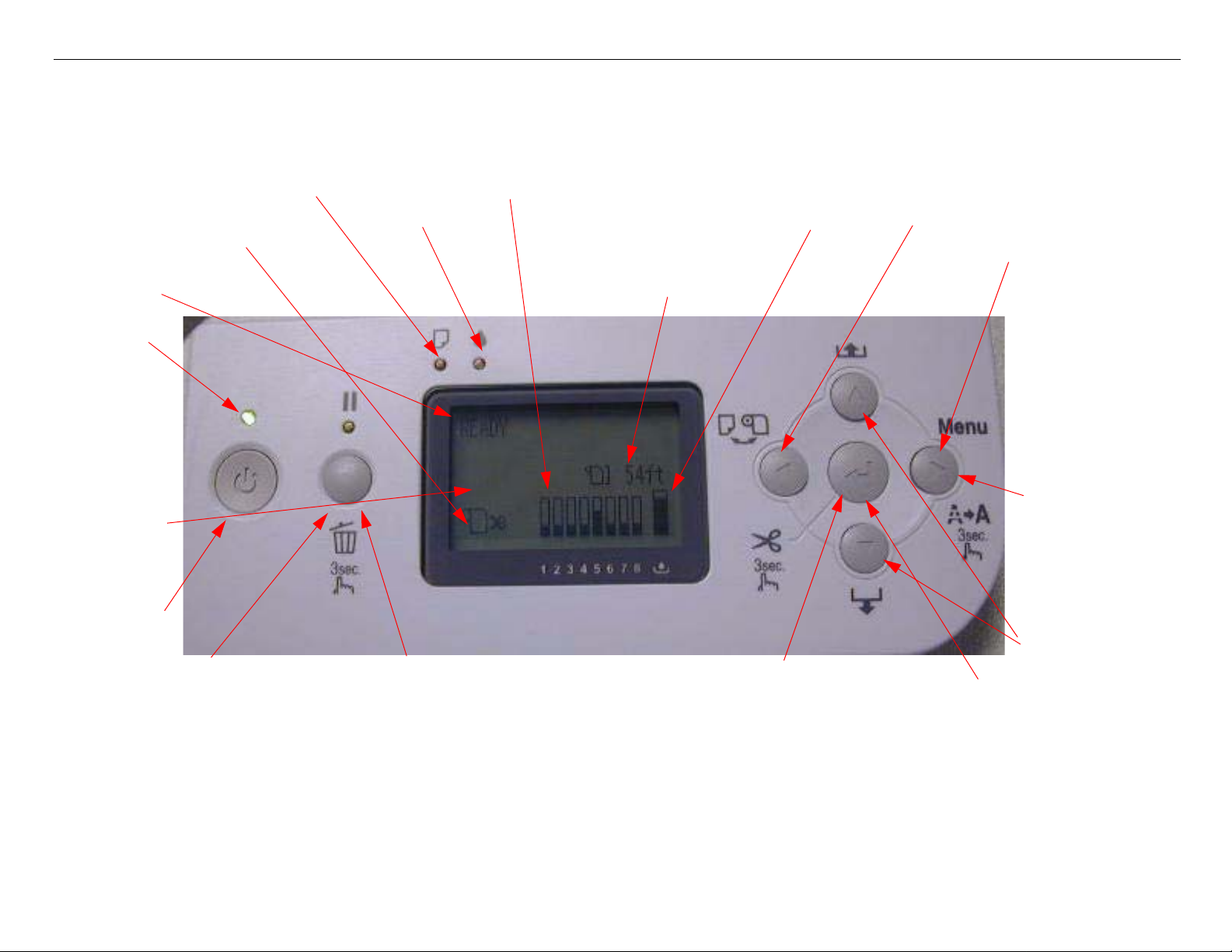
Control Panel Map
Sheet
Roll Auto Cut
Roll Auto Cut Off
Status
Paused
light
Custom
Paper
Number
Power
Button
Paper Out
Ink Out
Ink Levels
Maintenance
Tank Level
Roll Counter
Paper Source
Button
User
Menu
Button
Hold for 3
seconds to
clean
Media
Feed
Hold for
3 seconds to reset/clear
SERVICEMAN MODE: Down, Right, Pause, at power on.
SELF TESTING: Down, Right, Enter, at power on.
F/W DOWNLOAD MODE: Up, Down, Left, Right, at power on.
Maintenance Mode 1: Pause, at power on.
Press to pause the
Printer.
Printer Component, Software Item, LCD Display, Printer Button Page 7.
Enter / Select
Hold for 3 seconds
Button
to cut roll media
Page 8

Pro 7880 / 9880 Field Repair Guide 12/20/07
3. PRINTER STATUS.
User Menu: Press the Menu button when
the printer displays Ready
1. PRINTER SETUP.
ROLL PAPER COUNTER: 15ft - 300ft
PLATEN GAP: *STANDARD, NARROW, WIDE, WIDER,
WIDEST
PAGE LINE: *ON, OFF
INTERFACE: *AUTO, USB, NETWORK
CODE PAGE: *PC437, PC850,
ROLL PAPER MARGIN: *DEFAULT, TOP/BOTTOM 15mm,
TOP 35/BOTTOM 15mm,15mm, 3mm
PAPER SIZE CHK: *ON, OFF
PAPER SKEW CHECK: *ON, OFF
TIME OUT: *OFF, 30SEC, 60SEC, 180SEC, 300SEC
CUTTER ADJUSTMENT: EXEC
REFRESH MARGIN: *ON, OFF
AUTO NOZZLE CHECK: *OFF, ON
AUTO CLEANING: *ON, OFF
QUIET CUT: *OFF, ON
INITIALIZE SETTINGS: EXEC
2. TEST PRINT.
NOZZLE CHECK: PRINT
NETWORK STATUS SHEET: PRINT
STATUS SHEET: PRINT
JOB INFORMATION: PRINT
4. CUSTOM PAPER.
PAPER NUMBER: *STANDARD, NO. (1-10)
VERSION: (CURRENT FIRMWARE)
PRINTABLE PAGES: (FOR EACH COLOR)
(nnnnnn)PAGES
INK LEVEL: (FOR EACH COLOR) E*****F
MAINTENANCE TANK: L E*****F, R E*****F
USAGE COUNT: INK (nnnn.n)ML, PAPER (nnnn.n)FT
CLEAR USAGE COUNT: INK:EXEC PAPER:EXEC
JOB HISTORY: N0.(n) INK:(n)ml, PAPER:(nnn)sqft
TOTAL PRINTS: (n) PA GES
SERVICE LIFE: CUTTER, CR MOTOR, PF MOTOR,
HEAD UNIT,CLEANING UNIT, PRESSURE
MOTOR (E*****F)
PLATEN GAP: NARROW, STANDARD, WIDE, WIDER
THICKNESS PATTERN: PRINT
CUT METHOD: *STANDARD, THIN PAPER, THICK
PAPER FAST, THICK PAPER SLOW
PAPER FEED ADUST: (n.nn)%
DRYING TIME: (n.n)sec
PAPER SUCTION: *STANDARD, -1, -2, -3, -4
M/W ADJ: *STANDARD,1, 2
CUSTOM PAPER: PRINT
Printer Component, Software Item, LCD Display, Printer Button Page 8.
Page 9

Pro 7880 / 9880 Field Repair Guide 12/20/07
5. MAINTENANCE
CUTTER REPLACEMENT: EXEC
BK Ink Change: EXEC (For Changing between Matte and
Photo Black)
POWER CLEANING: “YOU MUST MOVE INK LEVERS
WHEN CLEANING”, EXECUTE, CANCEL (102ml)
CLOCK SETTING: (mm/dd/yy hh:mm)
CONTRAST ADJUSTMENT: (nn)
7. NETWORK SETUP: (*DISABLE, ENABLE)
IP ADDRESS SETTING: AUTO, PANEL,
BONJOUR: *ON, OFF
INIT NETWORK SETTING: EXECUTE
Parameter Backup and Restore Mode
6. Head Alignment.
PAPER THICKNESS: *STANDARD, (n.n)mm
ALIGNMENT: AUTO (UNI-D, BI-D 2-COLOR,
BI-D All, BI-D #1, BI-D #2,
BI-D #3)
MANUAL (UNI-D, BI-D 2-
COLOR, BI-D All,)
Release the Paper Lever, lift 2 Ink Levers, remove the Maintenance Tank, hold the Down, Right, and Pause but-
tons and turn on the Printer.
Note: If the backup procedure fails, try re-booting the Printer and letting it come Ready. Then try the
backup / restore procedure.
F/W Download Mode
Hold the Up, Down, Left, and Right buttons and turn on the power.
Maintenance Mode 1: Press and hold the Pause button and turn on the Printer.
HEX DUMP: PRINT EXEC (In this mode, the printer prints hexadecimal values received)
LANGUAGE: *ENGLISH, FRENCH, ITALIAN, GERMAN, SPANISH, PORTUGUE, DUTCH (Panel Language)
Printer Component, Software Item, LCD Display, Printer Button Page 9.
Page 10

Pro 7880 / 9880 Field Repair Guide 12/20/07
REMAINING PPR SETUP: *ROLL, OFF (Roll enables the ROLL PAPER COUNTER)
UNIT: *FEET/INCH, METER (Set’s the unit of measure that the printer displays)
CUT PRESSURE: *100% (0%-150%) (Adjusts the Paper Cutter pressure)
SS CLEANING: EXEC (Super Strong Cleaning)(255 time limit without replacing print head and resetting life
counter)
PWR ON ROLL PPR FEED: *ON, OFF (On = Feeds the paper 3” lower, when auto cut is off)
(Off = Does not feed the paper 3” lower, when auto cut is off)
DEF AULT PANEL: EXEC (Resets to Factory Default the following User Menus: Printer Setup, Printer St atus,
Custom Paper, Head Alignment)
INK INFO MENU: (FOR EACH COLOR) MANUF ACTURER, COLOR, INK TYPE, INK CAPACITY, INK LEVEL,
PRODUCTION DATE, EXPIRATION DATE, INK LIFE, INK AGE (CSIC
ink cartridge
)
information, for each
Custom:*0 (0 - 9)
SERVICEMAN MODE: Press and hold the Down, Right, and Pause buttons, and turn on the Printer
Note: SERVICEMAN MODE turns on the USB Port even if there is an error condition.
Note: SERVICEMAN MODE must be displayed on the LCD to turn on the USB Port.
SELF TESTING:
Test:
Version: F/W: T(N or W)(nnnnnnnn.nn.nnnn) (Displays the current firmware version)
Panel: Key, LCD, LED (Button, LCD, and LED tests for the control panel)
Sensor: CR Origin: On, Off (Carriage Home Position Sensor test)
Paper: 00, 01,10,11 (Paper Thickness Sensor test)
Lever: Down, Up (Paper Release Sensor test)
HeadSlide: On, Off (Platen Gap Home Position Sensor test)
Pump: On, Off (Pump Home Position Sensor test)
InkLvr: Down/Down, Up/Down, Down/Up, UP/Up (Right and Left Ink Lever Sensor test)
Cover: Close, Open (Cover Sensor test)
MainteTank: On, ON (CSIC Contact Test)
Printer Component, Software Item, LCD Display, Printer Button Page 10.
Page 11

Pro 7880 / 9880 Field Repair Guide 12/20/07
INK NOT: 1,2,3,4,5,6,7,8 (Ink Cartridge Sensor test for 8 Ink Bays)
EdgeAD: (nnn nnn) (Paper Edge Sensor test)
Edge2AD: (nnn nnn) (Ink Mark Sensor Test)
RearAD: (nnn nnn) (Rear Paper Sensor test)
Head Temp: (nn)C (Displays the current Print Head temperature in degrees centigrade)
Drv. Temp: (nn)C (Displays the current Print Head Driver temperature in degrees centigrade)
Ink Press: Off, On (Pressure Sensor test)
Take Up: (9880 Only) (Tests the absence, or presence of the Optional Take Up Reel)
Encoder: CR (nnnn) (Carriage Encoder test. Counts up, moving away from home position)
PF (nnnn) (Paper Feed Encoder test. Counts up, as the paper advances.)
Fan: Paper(ALL): (Fan test for all paper suction fans)
Paper(Duty): (200% - 0%) (Tests the fan suction for all paper suction fans)
Paper1: (Fan test for paper suction fan #1 (Right Side Fan))
Paper2: (Fan test for paper suction fan #2 (Left Side Fan (Center Fan on 9800)))
Paper3: (9880 only)(Fan test for paper suction fan #3 (Left Side Fan))
Head Drv: (Fan test for the Head Driver Cooling Fan)
Elec.: Maintenance: WasteInk: (Right Side Maintenance Tank Counter)
WasteInk2: (9880 Only)(Left Side Maintenance Tank Counter)
Wiper: (Wiping Counter)
Rubbing: (Rubbing Counter)
Lever: (Paper Release Lever Counter)
Cover: (Cover Sensor Counter)
Ink Lever: (Left and Right Ink Lever Counter)
Cr Motor: (Carriage Motor Usage Counter)
PF Motor: (Paper Feed Motor Usage Counter)
PrintNumber: (Number of printed pages)
Cleaning: (Cleaning Operations Counter)
Fire A: (Light Light Black Nozzle Array Counter)
Fire B: (Light Magenta Nozzle Array Counter)
Fire C: (Light Cyan Nozzle Array Counter)
Printer Component, Software Item, LCD Display, Printer Button Page 11.
Page 12

Pro 7880 / 9880 Field Repair Guide 12/20/07
Fire D: (Light Black Nozzle Array Counter)
Fire E: (Photo/Matte Black Nozzle Array Counter)
Fire F: (Cyan Black Nozzle Array Counter)
Fire G: (Magenta Nozzle Array Counter)
Fire H: (Yellow Nozzle Array Counter)
Cut: (Paper Cutting Operations Counter)
Cute Sole: (Cutter Solenoid Counter)
Error: Error (0 - 6) (Displays the last 7 errors)
Cut Adj: Cutter: 55%
Actuator2: Cutter Sol: [Enter], Start (Tests the Cutter Solenoid)
Pump Motor: [Enter], Start (Tests the Cutter Solenoid)
Regulator Sol: [Enter], Start (Tests the Ink System Pressure Release Solenoid)
Ink Press Motor: [Enter], Start (Ink System Pressure Motor)
Edge Sns Lvl: [Enter], Start (Sets the black level of the Edge Detector)
Auto Gap Adj: Auto Uni-D: [Enter] Print (Performs and Auto Uni-D Adjustment)
Auto Bi_d PG1.6: [Enter] Print (Performs and Auto Bi-D for Platen Gap 1.6 (WIDE))
Auto Bi_d PG0.8: [Enter] Print (Performs and Auto Bi-D for Platen Gap 0.8 (NARROW))
Adjustment:
Fan: Paper(ALL)(Runs all Suction Fans), Fan Adjust *0% (-10% to +10%) (Adjusts Suction Fans)
Paper: 00, 01, 10, 11(Displays the output from the Paper Thickness Sensors)
RearAD: [Enter], Start: Exc.: RearAD: (nnn nnn nnn) (For adjusting the Rear Paper Sensor)
Check Nozzle: [Enter] Print: (Service nozzle check, displays Firmware Version, displays Head Rank)
Cutter: [Enter], Start:(Cut position check)
IM Sensor: (Adjusts sensitivity of the Edge Detector Sensor and the Ink Mark Sensor)
PlatenPos: (n.n)mm(Calibrates the Borderless Pad Positions)
PlatenPos.Chk.: (Checks the Borderless Pad Position calibration)
Rear Sens.Pos: (Calibrates the EOF position for cut sheet media)
CR Head Slant: (Performs the CR Head Slant adjustment)
PF Head Slant: PF Head BiD Adj (Pk or MK Bi-D adjustment), PF Head Slant (PF Head Slant adjust-
ment)
Printer Component, Software Item, LCD Display, Printer Button Page 12.
Page 13

Pro 7880 / 9880 Field Repair Guide 12/20/07
Gap Adj: All, Uni-D, Bi-D PG1.6,Bi-D PG0.8, (Manual Bi-D and Uni-D)
Gap Adj: VSD1C: Print (Manual Bi-D and Uni-D PG 1.2)
Check Skew: (n.n)mm (Default 1.0) (Used for testing and setting the amount of allowable skew)
Feed Adj.+T&B: (Performs the 980mm, Top and Bottom Margin adjustments)
IM Thresh: IM PosAdj, IM Loss Pattern, IM Full Pattern (Calibrates the IM Sensor for Auto Nozzle Check)
Adj. Variable: [Enter] Print (Prints the numeric adjustment variables currently set)
Pump Cnt: NG(?)
VIEW COUNTERS:
CUTTER: (Count for the Cutter Blade)
CUTTER TOTAL: (Count for the Cutter Assembly)
TOTAL PAGES: (Page count for the Printer)
CR MOTOR: (Count for the Carriage Motor)
CR TOTAL: (Count for the Carriage Mechanism)
PF MOTOR: (Count for the Paper Feed Motor)
PRESSURE MOTOR: (Count for the Pressure Motor)
NOZZLE A: (Light Light Black Nozzle Array Counter)
NOZZLE B: (Light Magenta Nozzle Array Counter)
NOZZLE C: (Light Cyan Nozzle Array Counter)
NOZZLE D: (Light Black Nozzle Array Counter)
NOZZLE E: (Photo/Matte Black Nozzle Array Counter)
NOZZLE F: (Cyan Black Nozzle Array Counter)
NOZZLE G: (Magenta Nozzle Array Counter)
NOZZLE H: (Yellow Nozzle Array Counter)
FL BOX: (Count for the Flushing Box)
CLEANER: (Count for the Pump and Cap Assembly)
SPONGE: (?)
PG: (Count for the Platen Gap Assembly)
MAINT INFO:
MENU E: E1 - E17 (?)
MENU R: R1 - R9 (?)
Printer Component, Software Item, LCD Display, Printer Button Page 13.
Page 14

Pro 7880 / 9880 Field Repair Guide 12/20/07
MENU S: S1 - S26 (?)
MENU A: A1 - A32 (?)
MENU B: B1 - B48 (?)
MENU P: P1 - P46 (?)
MENU M: M1 - M26 (?)
MENU O: 01 - 026 (?)
MENU F: F1- F20 (?)
MENU N: N1 - N22 (?)
SELF TESTING: Press and hold the Down, Right, and Enter buttons and turn on the Printer.
Test:
Version: F/W: T(N or W)(nnnnnnnn.nn.nnnn) (Displays the current firmware version)
Panel: Key, LCD, LED (Button, LCD, and LED tests for the control panel)
Sensor: CR Origin: On, Off (Carriage Home Position Sensor test)
Paper: 00, 01,10,11 (Paper Thickness Sensor test)
Lever: Down, Up (Paper Release Sensor test)
HeadSlide: On, Off (Platen Gap Home Position Sensor test)
Pump: On, Off (Pump Home Position Sensor test)
InkLvr: Down/Down, Up/Down, Down/Up, UP/Up (Right and Left Ink Lever Sensor test)
Cover: Close, Open (Cover Sensor test)
MainteTank: On, Off (CSIC Contact Test)
INK NOT: 1,2,3,4,5,6,7,8 (Ink Cartridge Sensor test for 8 Ink Bays)
EdgeAD: (nnn nnn) (Paper Edge Sensor test)
Edge2AD: (nnn nnn) (Ink Mark Sensor Test)
RearAD: (nnn nnn) (Rear Paper Sensor test)
Head Temp: (nn)C (Displays the current Print Head temperature in degrees centigrade)
Drv. Temp: (nn)C (Displays the current Print Head Driver temperature in degrees centigrade)
Ink Press: Off, On (Pressure Sensor test)
Take Up: (9800 Only) (Tests the absence, or presence of the Optional Take Up Reel)
Encoder: CR (nnnn) (Carriage Encoder test. Counts up, left to right)
Printer Component, Software Item, LCD Display, Printer Button Page 14.
Page 15

Pro 7880 / 9880 Field Repair Guide 12/20/07
PF (nnnn) (Paper Feed Encoder test. Counts up, as the paper advances.)
Fan: Paper(ALL): (Fan test for all paper suction fans)
Paper(Duty): (200% - 0%) (Tests the fan suction for all paper suction fans)
Paper1: (Fan test for paper suction fan #1 (Right Side Fan))
Paper2: (Fan test for paper suction fan #2 (Left Side Fan (Center Fan on 9800)))
Paper3: (9800 only)(Fan test for paper suction fan #3 (Left Side Fan))
Head Drv: (Fan test for the Head Driver Cooling Fan)
Elec.: Maintenance: WasteInk: (Right Side Maintenance Tank Counter)
WasteInk2: (9880 Only)(Left Side Maintenance Tank Counter)
Wiper: (Wiping Counter)
Rubbing: (Rubbing Counter)
Lever: (Paper Release Lever Counter)
Cover: (Cover Sensor Counter)
Ink Lever: (Left and Right Ink Lever Counter)
Cr Motor: (Carriage Motor Usage Counter)
PF Motor: (Paper Feed Motor Usage Counter)
PrintNumber: (Number of printed pages)
Cleaning: (Cleaning Operations Counter)
Fire A: (Light Light Black Nozzle Array Counter)
Fire B: (Light Magenta Nozzle Array Counter)
Fire C: (Light Cyan Nozzle Array Counter)
Fire D: (Light Black Nozzle Array Counter)
Fire E: (Photo/Matte Black Nozzle Array Counter)
Fire F: (Cyan Black Nozzle Array Counter)
Fire G: (Magenta Nozzle Array Counter)
Fire H: (Yellow Nozzle Array Counter)
Cut: (Paper Cutting Operations Counter)
Cute Sole: (Cutter Solenoid Counter)
Error: Error(0 - 6) (Displays the last 7 errors)
CSIC: Slot (1 - 8), Maintenance Tank (?)
Printer Component, Software Item, LCD Display, Printer Button Page 15.
Page 16

Pro 7880 / 9880 Field Repair Guide 12/20/07
Cut Adj: Cutter: 55%
Actuator2: Cutter Sol: [Enter], Start (Tests the Cutter Solenoid)
Pump Motor: [Enter], Start (Tests the Cutter Solenoid)
Regulator Sol: [Enter], Start (Tests the Ink System Pressure Release Solenoid)
Ink Press Motor: [Enter], Start (Ink System Pressure Motor)
Edge Sns Lvl: [Enter], Start (Sets the black level of the Edge Detector)
Auto Gap Adj: Auto Uni-D: [Enter] Print (Performs the Auto Uni-D Adjustment)
Auto Bi_d PG1.6: [Enter] Print (Performs the Auto Bi-D for Platen Gap 1.6 (WIDE))
Auto Bi_d PG0.8: [Enter] Print (Performs the Auto Bi-D for Platen Gap 0.8 (NARROW))
Adjustment:
Input HeadRank: (Does not function)
Fan: Paper(ALL)(Runs all Suction Fans), Fan Adjust *0% (-10% to +10%) (Adjusts Suction Fans)
Paper: 00, 01, 10, 11(Displays the output from the Paper Thickness Sensors)
Rear AD: [Enter], Start: Exc.: RearAD: (nnn nnn nnn) (For adjusting the Rear Paper Sensor)
Init.Fill: (Starts an initial fill)
Check Nozzle: [Enter] Print: (Service nozzle check, displays Firmware Version, displays Head Rank)
Cutter: (Cut position check)
IM Sensor: (Adjusts sensitivity of the Edge Detector Sensor)
PlatenPos: (n.n)mm(Calibrates the Borderless Pad Positions)
PlatenPos.Chk.: (Checks the Borderless Pad Position calibration)
Rear Sens.Pos: (Calibrates the EOF position for cut sheet media)
CR Head Slant: (Performs the CR Head Slant adjustment)
PF Head Slant: PF Head Slant (PF Head Slant adjustment), PF Head BiD Adj (Pk or MK Bi-D adjust-
ment)
Gap Adj: All, Uni-D, Bi-D PG1.6,Bi-D PG0.8, (Manual Bi-D and Uni-D)
Gap Adj: VSD1C: Print (Manual Bi-D and Uni-D PG 1.2)
Check Skew: (n.n)mm (Default 1.0) (Used for testing and setting the amount of allowable skew)
Feed Adj.+T&B: (Performs the 980mm, Top and Bottom Margin adjustments)
IM Thresh: IM PosAdj, IM Full Pattern, IM Loss Pattern (Calibrates the IM Sensor for Auto Nozzle Check)
Adj. Variable: [Enter] Print (Prints the numeric adjustment variables currently set)
Printer Component, Software Item, LCD Display, Printer Button Page 16.
Page 17

Pro 7880 / 9880 Field Repair Guide 12/20/07
Clean Head: (Evacuates the ink system)
Pump Cnt: NG(?)
Counter Clear: (Clears a variety of counters)(Do not use)
Cleaning:
Std. CL1 (5.3ml)
Std. CL2 (6.3ml)
Std. CL3 (10.4ml)
Std. CL6 (?)
Init.Fill
Parameter:
Initialize:
All: Initialize OK? (Resets all of the following counters at once)
PF Resolution: Initialize OK? (Resets this counter only)
Head Record: Initialize OK? (Resets this counter only)
Wiping Record: Initialize OK? (Resets this counter only)
Rab. Record: Initialize OK? (Resets this counter only)
Waste Record: Initialize OK? (Resets this counter only)
CRmot Record: Initialize OK? (Resets this counter only)
PFmot Record: Initialize OK? (Resets this counter only)
Lever Record: Initialize OK? (Resets this counter only)
Cover Record: Initialize OK? (Resets this counter only)
Ink Lever Record: Initialize OK? (Resets this counter only)
Cutter Record: Initialize OK? (Resets this counter only)
Cleaner Record: Initialize OK? (Resets this counter only)
Update: JM: Init. Fill: (Set, Reset) (Reset, turns of f the initial fill)
InkParameter: Init. Fill: (Set, Reset) (Reset, turns off the initial fill)
HeadWash(?)
Mask Type: Dispersion, Regular (?)
PF BiD Adjust: (+/- n) (?)
Uni-D Trap: (On, Off) (?)
Printer Component, Software Item, LCD Display, Printer Button Page 17.
Page 18

Pro 7880 / 9880 Field Repair Guide 12/20/07
Display: Address: (nnnn)(Used for displaying data at specific RAM addresses)
Life: CR Motor (Carriage Motor Life Counter)
PF Motor (Paper Feed Motor Life Counter)
CR+PF Motor(Carriage and Paper Feed Motor Life Counter)
Cutter (Cutter Assembly Life Counter)
Head U/D (?)
Head Lock (Head Lock Assembly Life Counter)
Cleaning (Cleaning Unit Life Counter)
Print (Print Head Life Counter)
Total Life (?)
TotalLife2 (?)
CSIC (?)
Check (?)
Printer Component, Software Item, LCD Display, Printer Button Page 18.
Page 19

Pro 7880 / 9880 Field Repair Guide 12/20/07
Component
Replacement
Printer Component, Software Item, LCD Display, Printer Button Page 19.
Page 20
Pro 7880 / 9880 Field Repair Guide 12/20/07
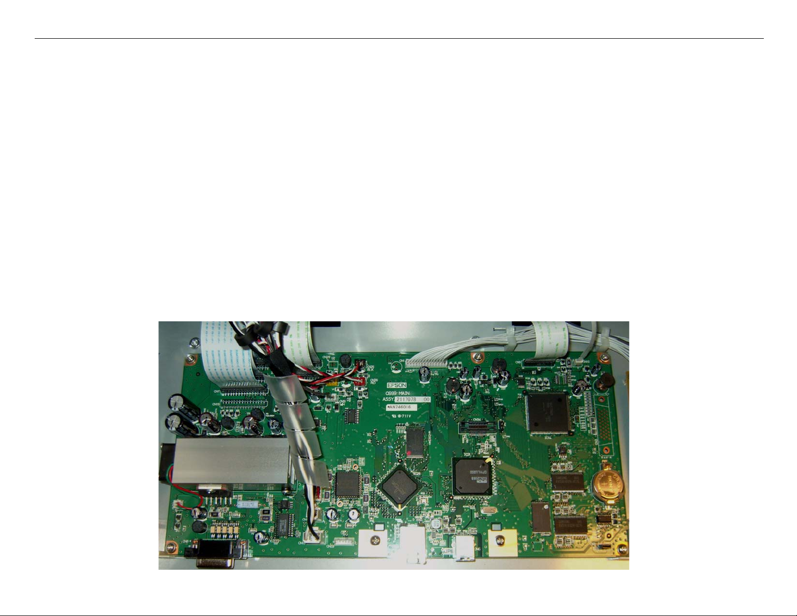
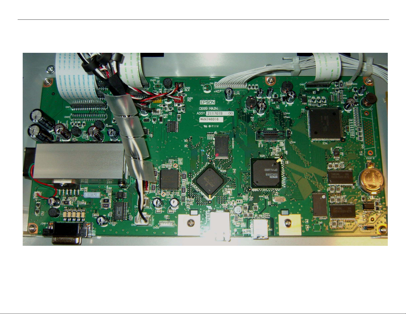
Board (Main) Removal
Note: 7880 Main Board Part # 2117093 (the part # is stamped on the board)
9880 Main Board Part # 2117078 (the part # is stamped on the board)
1. Back up the Printer’s parameters using the Parameter Backup / Restore Utility (Nvram.exe)
Note: If the Printer’s parameters can not be “backed up”, print out the Print Head Calibration value
(Head Rank). The Print Head Calibration value is printed on the Service Level Nozzle Check
(ServiceMan Mode: Self Testing: Adjustment: Check Nozzle).
2. Turn off the Printer and UNPLUG from AC.
3. Remove the Cover (Rear).
4. Unplug the Cables that attach the Main Board to the Printer..
Board (Main) Removal Printer Component, Software Item, LCD Display, Printer Button Page 20.
Page 21
Pro 7880 / 9880 Field Repair Guide 12/20/07
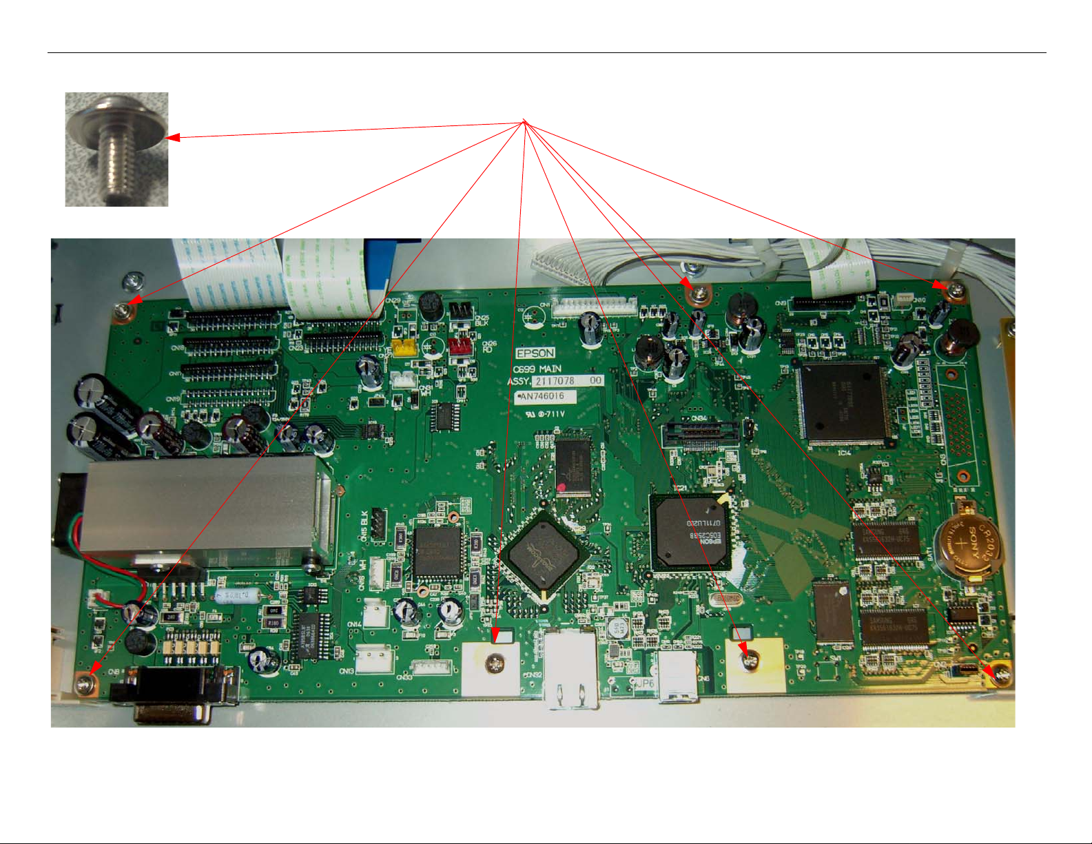
5. Remove 7 Screws, and lift out the Main Board.
1. Remove 7 Screws
2. Lift out the Main Board.
Board (Main) Removal Printer Component, Software Item, LCD Display, Printer Button Page 21.
Page 22
Pro 7880 / 9880 Field Repair Guide 12/20/07
Board (Main) Installation
Note: 7880 Main Board Part # 2117093 (the part # is stamped on the board)
9880 Main Board Part # 2117078 (the part # is stamped on the board)
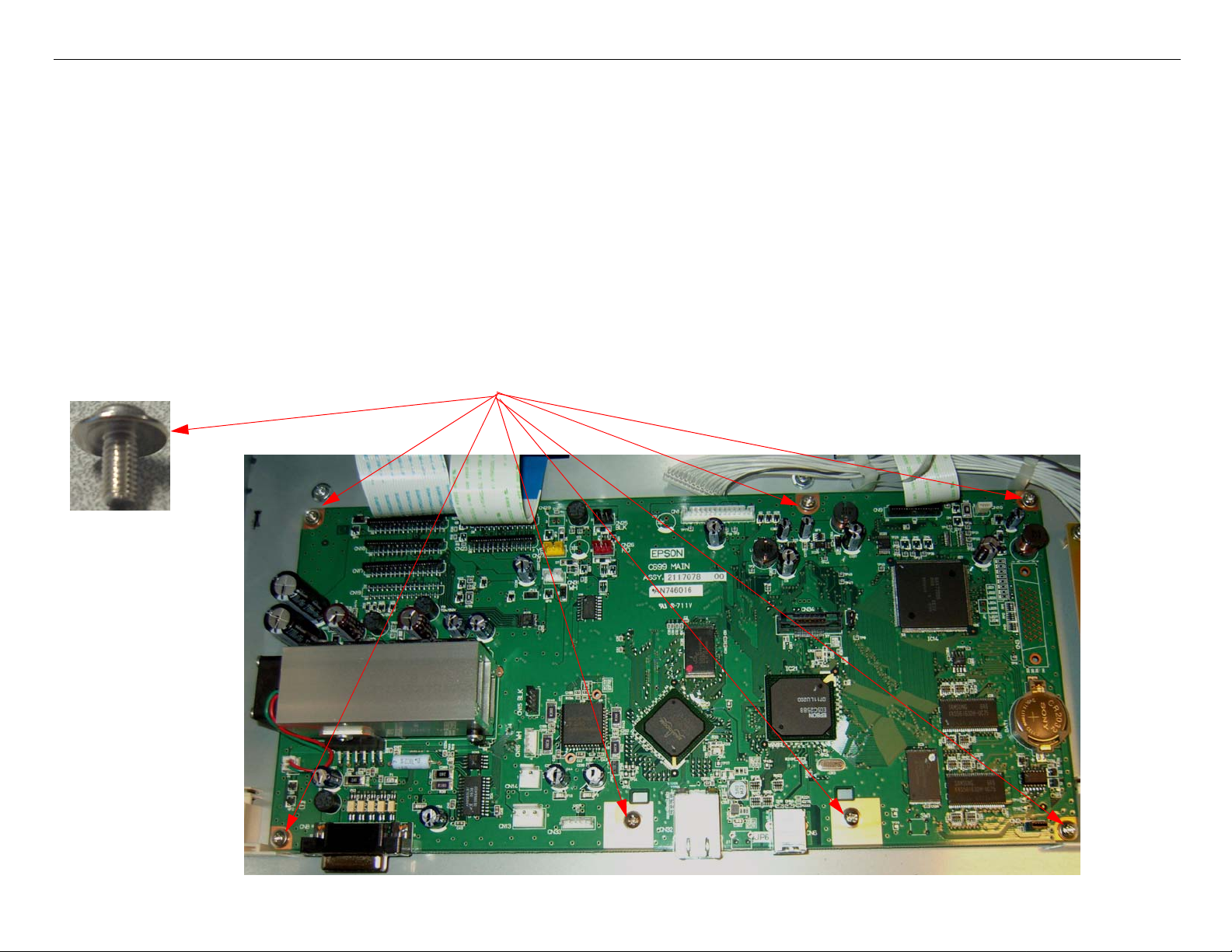
1. Compare the New Main Board to the Old Main Board. Verify that the Components, Brackets,
and Part Numbers match.
2. Fasten the new Board to the Housing with 7 Screws (see above).
1. Drop In the New Main Board.
2. Install 7 Screws.
Board (Main) Installation Printer Component, Software Item, LCD Display, Printer Button Page 22.
Page 23
Pro 7880 / 9880 Field Repair Guide 12/20/07
3. Connect the Cables to the Board. Ensure that the Cables are fully seated (straight).
Board (Main) Installation Printer Component, Software Item, LCD Display, Printer Button Page 23.
Page 24

Pro 7880 / 9880 Field Repair Guide 12/20/07
4. Install the Rear Cover.
5. Plug in and turn on the Printer in Firmware Download Mode (depress the Up, Down, Left, and
Menu buttons, and turn on the power to the Printer).
6. Download the latest Firmware following the directions found in the Firmware Update Procedure
Using FWUpdate.exe chapter located in the Reference section of the Field Guide.
If the Printer’s Parameters are not available skip step 7, and proceed with step 8.
7. Re-Install the Printer’s parameters using the Parameter Backup / Restore Utility (Nvram.exe)
7.1 Perform the RTC&USBID&IEEE1394ID Adjustment.
7.2 Perform the Colorimetric Calibration (When specifically requested by Epson).
8. Install the appropriate generic Printer parameters using the Parameter Backup / Restore Utility
(Nvram.exe)
Note: If the new Board does not have any parameters, the Printer will not function well enough to allow
alignments, paper loading, nozzle check, or the rest of step 16. Generic parameters are a set of
working parameters from another printer. They are available for download at: https://
www.epsoninsider.com listed under the Printer name, as Generic NVRAM Backup. They come in 4
variations (7880 Matte Black, 7880 Photo Black, 9880 Matte Black, and 9880 Photo Black)
Board (Main) Installation Printer Component, Software Item, LCD Display, Printer Button Page 24.
Page 25

Pro 7880 / 9880 Field Repair Guide 12/20/07
9. Perform the following operations in the order listed.
9.1 Perform the RTC&USBID Adjustment.
9.2 Enter the Head Rank ID (Print Head calibration values).
9.3 Perform Input Serial Number.
9.4 Perform the Rear Sensor Adjustment.
9.5 Perform the 980mm Feed Adjustment
9.6 Perform the Ink Mark Sensor Level Adjustment.
9.7 Perform the T&B&S (Roll Paper) Adjustment.
9.8 Perform the T&B&S (Cut Sheet) Adjustment.
9.9 Perform the Platen Position Adjustment
9.10 Perform the Ink Mark Sensor Adjustment for Auto Nozzle Check.
9.11 Perform the Auto Bi-D Adjustment.
9.12 Perform the Auto Uni-D Adjustment.
9.13 Perform the Cutter Pressure Adjustment.
9.14 )Perform the Writing MAC Address Adjustment.
9.15 Perform the Colorimetric Calibration (When specifically requested by Epson).
10. Turn the Printer off, and then back on, to ensure that the new data from step 16 is loaded into the
Printer’s memory.
Board (Main) Installation Printer Component, Software Item, LCD Display, Printer Button Page 25.
Page 26
Pro 7880 / 9880 Field Repair Guide 12/20/07
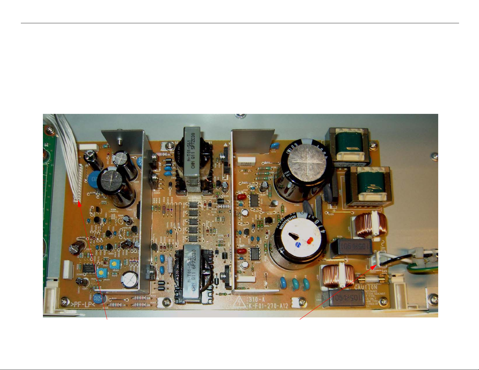
Board (Power Supply) Removal
1. Turn off the Printer and UNPLUG from AC.
2. Remove the Cover (Rear).
3. Unplug the Cables that attach the Power Supply to the Printer..
1. Unplug CN301.
Board (Power Supply) Removal Printer Component, Software Item, LCD Display, Printer Button Page 26.
2. Unplug CN001.
Page 27
Pro 7880 / 9880 Field Repair Guide 12/20/07
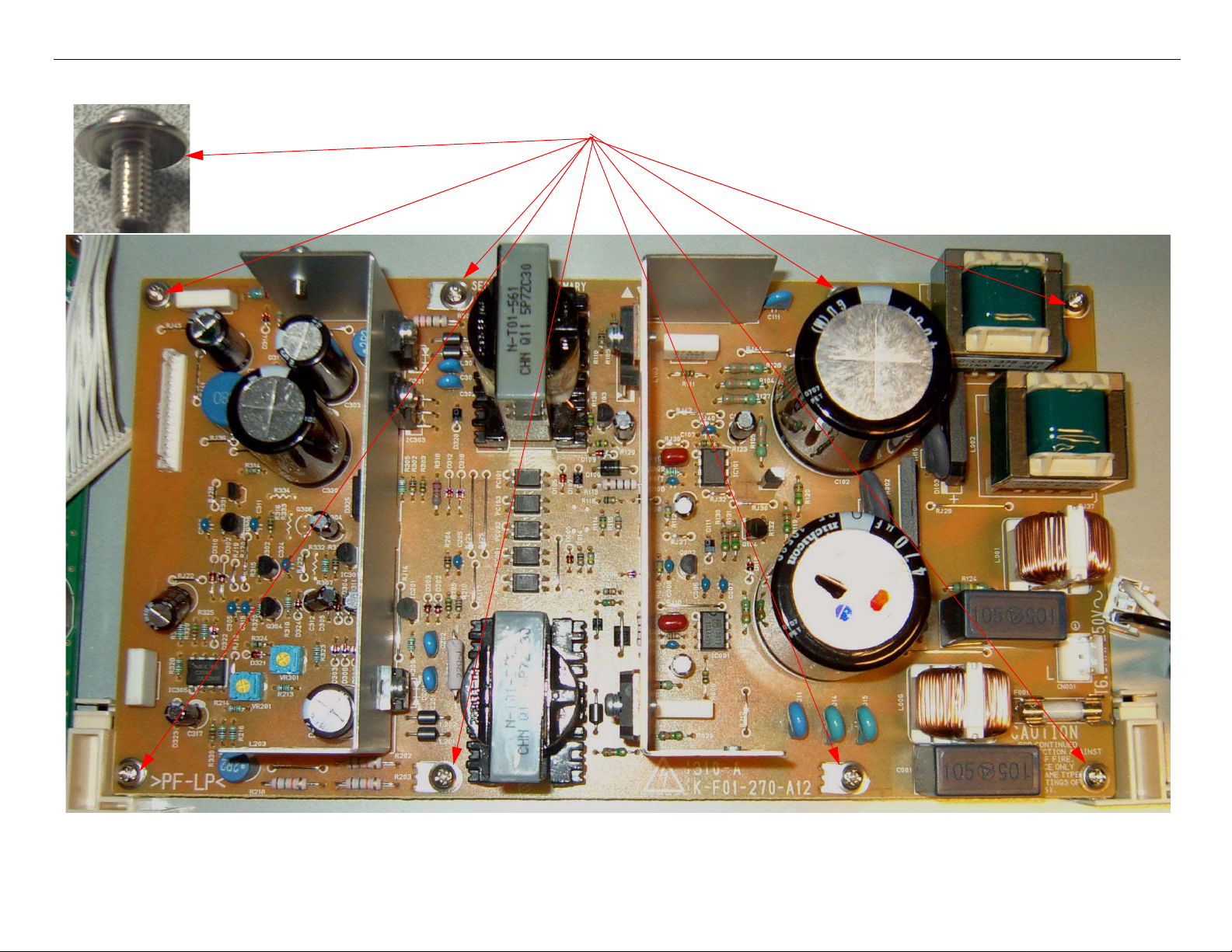
4. Remove 8 Screws, and lift out the Power Supply..
1. Remove 8 Screws
2. Lift out the Power Supply.
Board (Power Supply) Removal Printer Component, Software Item, LCD Display, Printer Button Page 27.
Page 28
Pro 7880 / 9880 Field Repair Guide 12/20/07
Carriage Assembly Replacement Procedure
Required Parts: New Carriage, Part # 1291960 & Cutter Alignment tool, Part # 1212928
1. Unplug the Printer.
2. Raise both Ink Levers, closing the Ink Valves.
3. Remove the Top Cover, Left Side Cover, and Right Side Cover.
4. Release the Carriage Lock, and move the Carriage Mechanism to the center of the Printer.
5. Remove the Pump Cap Assembly.
6. Remove the Carriage Board Cover.
Loosen 1 Screw.
Carriage Assembly Replacement Procedure Printer Component, Software Item, LCD Display, Printer Button Page 28.
Lift off the Carriage Board Cover.
Page 29
Pro 7880 / 9880 Field Repair Guide 12/20/07
p
7. Remove 2 Screws that fasten the Carriage Board Assembly.
Remove 2 Screws.
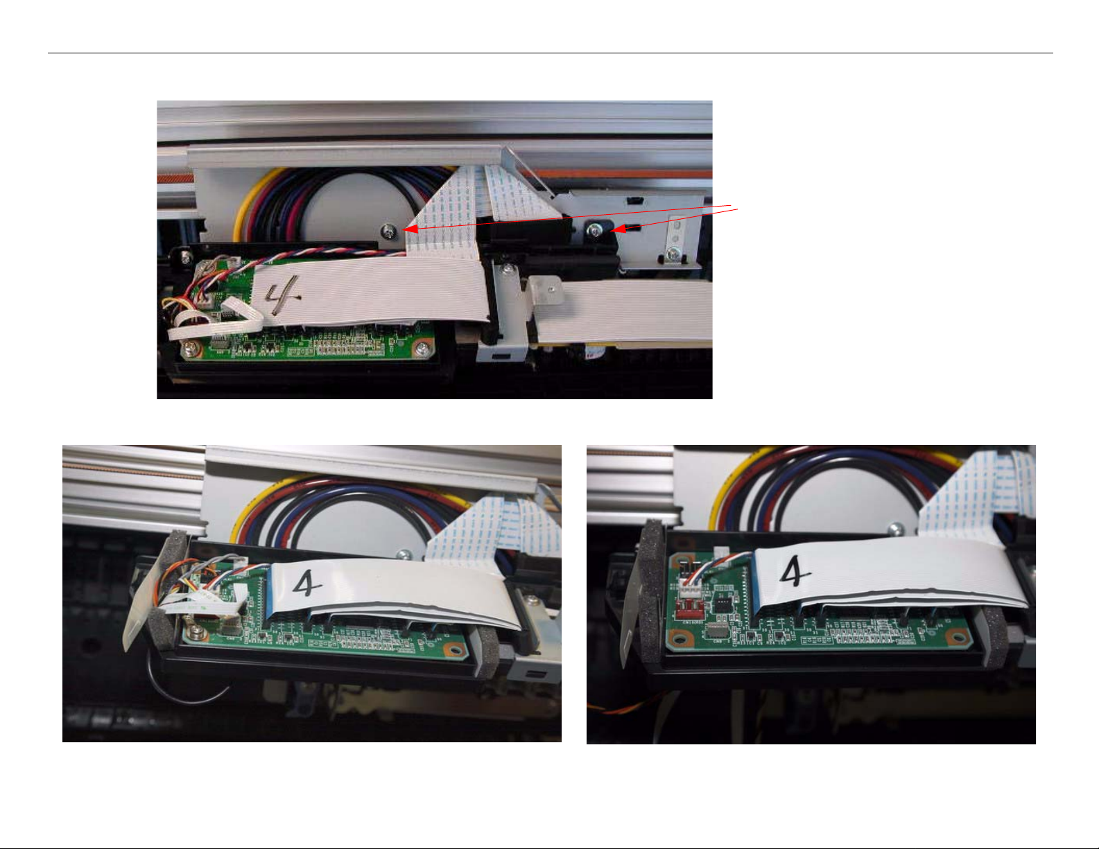
8. Disconnect 5 Cables
Disconnect 2 foil cables and 3 connectors.
Remove 1 screw that fastens the Ground Stra
Carriage Assembly Replacement Procedure Printer Component, Software Item, LCD Display, Printer Button Page 29.
Wire.
Page 30
Pro 7880 / 9880 Field Repair Guide 12/20/07
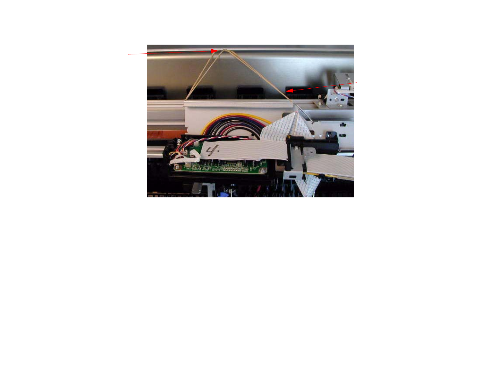
9. Lift and suspend the Carriage Board Assembly.
Loosen one of the Screws
that fasten a cover to support
the Carriage Board Assem-
bly.
Lift up the Carriage Board
Assembly, and suspend it
from the loosened Screw.
(Shown with rubber bands
in the picture).
Carriage Assembly Replacement Procedure Printer Component, Software Item, LCD Display, Printer Button Page 30.
Page 31

Pro 7880 / 9880 Field Repair Guide 12/20/07
10. Remove 2 Screws that fasten the Damper Assembly to the Carriage Assembly.
Remove 2 Screws that are to the left and the right
to the Damper Bracket.
Right side Screw shown from the
side.
11. Lift off the Damper Assembly and suspend it from the same Screw used in step 8.
Carriage Assembly Replacement Procedure Printer Component, Software Item, LCD Display, Printer Button Page 31.
Page 32

Pro 7880 / 9880 Field Repair Guide 12/20/07
12. Remove 2 Screws, 1 Spring, and the Tension Bar that fasten the Print Head Assembly.
Remove 2 Screws.
Remove Tension Bar and Spring.
13. Remove the Print Head Ground Strap Screw.
Support the Bracket so that it does
not bend, and remove 1 Screw.
Carriage Assembly Replacement Procedure Printer Component, Software Item, LCD Display, Printer Button Page 32.
Page 33

Pro 7880 / 9880 Field Repair Guide 12/20/07
14. Slide the Print Head Assembly in the direction shown, and lift it out. Place it on the side.
15. Disconnect 5 Cables
Disconnect 2 foil cables and 3 connectors.
Remove 1 screw that fastens the Ground Strap Wire.
Carriage Assembly Replacement Procedure Printer Component, Software Item, LCD Display, Printer Button Page 33.
Page 34

Pro 7880 / 9880 Field Repair Guide 12/20/07
16. Place a tape on Locking Lever to disengage Locking Mechanism.
Place tape here
17. Remove the Paper Release Lever.
Remove the E-ring and Spring Pull the Paper Release Lever out.
Carriage Assembly Replacement Procedure Printer Component, Software Item, LCD Display, Printer Button Page 34.
Page 35

Pro 7880 / 9880 Field Repair Guide 12/20/07
18. Unhook Timing Fence from the right side.
Unhook T-fence here
19. Remove the Right Side Gear Assy.
Remove 5 screws and slide the Gear Assy out
Carriage Assembly Replacement Procedure Printer Component, Software Item, LCD Display, Printer Button Page 35.
Page 36

Pro 7880 / 9880 Field Repair Guide 12/20/07
20. Remove T-Fence Hook Plate.
Remove 2 screws and
take off the T-fence Hook
21. Remove the Belt and Pulley from Carriage Assy.
Remove 1 screw and remove Pulley. Remove Belt from Fastener
Carriage Assembly Replacement Procedure Printer Component, Software Item, LCD Display, Printer Button Page 36.
Page 37

Pro 7880 / 9880 Field Repair Guide 12/20/07
22. Remove the Belt Tensioner Bracket
Remove the Belt Tensioned Bracket. Beware of the Spring here.
23. Remove the CR Encoder.
Remove 2 screws.
Carriage Assembly Replacement Procedure Printer Component, Software Item, LCD Display, Printer Button Page 37.
Page 38

Pro 7880 / 9880 Field Repair Guide 12/20/07
24. Slide the Carriage Assembly out.
25. Remove the Cutter Assembly and Multisensor from the old Carriage Assembly.
Remove 2 screws and take off the Cutter
Assy.
Carriage Assembly Replacement Procedure Printer Component, Software Item, LCD Display, Printer Button Page 38.
Remove 1 screw and remove the Multisenser
Page 39

Pro 7880 / 9880 Field Repair Guide 12/20/07
26. Remove the Weights and transfer the Weights, Cutter Assembly and Multisensor to the new
Carriage Assembly.
Remove 4
screws and
transfer the
Weights to New
Carriage Assy.
Install Multisense,
make sure it is in
the correct alignment holes.
Install Cutter Assy
back, 2 Screws.
Carriage Assembly Replacement Procedure Printer Component, Software Item, LCD Display, Printer Button Page 39.
Page 40

Pro 7880 / 9880 Field Repair Guide 12/20/07
27. Slide new Carriage Assy back on to the Rail.
When sliding Carriage
Assy. back on, be
aware that the T -fence
needs to be here.
28. Install T-Fence Hook Plate.
2 screws here
Make sure the T-Fence
hooks on to here.
Carriage Assembly Replacement Procedure Printer Component, Software Item, LCD Display, Printer Button Page 40.
Page 41

Pro 7880 / 9880 Field Repair Guide 12/20/07
29. Install the Belt Tensioner Bracket
30. Install Belt, Pulley and Tensioner Plate
1. Put on Pulley, make
sure White Nylon Ring is
facing toward the front.
2. Make sure the Belt
is hooked on to the
Carriage Motor.
3. The ribs on the Belt
end at the right side of
the Fastener
4.Turn the Adjustment Screw
until the Belt Bracket is positioned between 2 long marks in
the center.
Carriage Assembly Replacement Procedure Printer Component, Software Item, LCD Display, Printer Button Page 41.
Page 42

Pro 7880 / 9880 Field Repair Guide 12/20/07
31. Install the CR Encoder.
2 Screws
32. Adjust the Carriage Encoder Sensor, until it is centered on the Carriage Encoder Strip.
1. Loosen 2 Screws so that
the Carriage Encoder can
be shifted forward and
back.
2. Sight down the Encoder Strip
and adjust the position of the
Carriage Encoder until it is
centered on the Encoder
Strip.
Note: Move the Carriage Assembly
and sight down the Strip. If
the Encoder is not centered,
the Strip will subtilely shift
3. Tighten 2 Screws when adjusted.
position. Adjust until the shifting is minimized.
Carriage Assembly Replacement Procedure Printer Component, Software Item, LCD Display, Printer Button Page 42.
Page 43

Pro 7880 / 9880 Field Repair Guide 12/20/07
33. Install the Right Side Gear Assy.
5 screws
34. Install the Paper Release Lever.
1. Insert Paper Release
Lever and install the ERing. Push the Paper
Release Rod from the left
side to install the E-Ring
properly.
2. Install the Spring.
Carriage Assembly Replacement Procedure Printer Component, Software Item, LCD Display, Printer Button Page 43.
Page 44

Pro 7880 / 9880 Field Repair Guide 12/20/07
35. Slide the Print Head Assembly into the Carriage Mechanism.
The Left and Right
Plastic Tabs on the
Print Head Assembly go under these
Plastic Wheels.
36. Ensure that the Head Assembly Interlock Tabs are inserted into the Carriage Assembly Slots.
Head Assembly Interlock
Tabs are inserted into the Carriage Assembly Slots
Carriage Assembly Replacement Procedure Printer Component, Software Item, LCD Display, Printer Button Page 44.
Page 45

Pro 7880 / 9880 Field Repair Guide 12/20/07
37. Attach the Print Head Ground Strap with 1 Screw.
Attach the Print Head Ground
Strap with 1 Screw.
38. Install the Tension Bar, that fastens the Print Head Assembly.
1. Install the Spring.
2. Install this Screw loosely.
3. Flex the Tension Bar
into position and then
insert the Screw.
Carriage Assembly Replacement Procedure Printer Component, Software Item, LCD Display, Printer Button Page 45.
Page 46

Pro 7880 / 9880 Field Repair Guide 12/20/07
39. Install the Damper Assembly, and fasten with 2 Screws.
1. Lower the Damper Assem-
bly onto the Print Head, and
press onto the Print Head
firmly.
2. Fasten with 2 Screws, 1
Screw on each side.
Carriage Assembly Replacement Procedure Printer Component, Software Item, LCD Display, Printer Button Page 46.
Page 47

Pro 7880 / 9880 Field Repair Guide 12/20/07
40. Attach the Carriage Board Assembly with 2 Screws.
1.Ensure that the Platen
Gap Sensor and the
Platen Gap Wheel are
in the correct position.
2. Fasten the Carriage Board
Assembly with 2 Screws.
Carriage Assembly Replacement Procedure Printer Component, Software Item, LCD Display, Printer Button Page 47.
Page 48

Pro 7880 / 9880 Field Repair Guide 12/20/07
41. Route and connect 5 Cables for the Carriage Board.
Cables go through here.
Make sure the Cables
are in the holder.
Connect 2 Foil Cables and 3 Connectors.
1 Screw that fastens the Ground Strap Wire.
Carriage Assembly Replacement Procedure Printer Component, Software Item, LCD Display, Printer Button Page 48.
Page 49

Pro 7880 / 9880 Field Repair Guide 12/20/07
42. Install the Carriage Board Cover and fasten with 1 Screw.
1. Engage the Cover
with the Hinge.
2. Fasten with 1
Screw.
43. Perform Cutter Blade Position Adjustment.
44. Plug in the Printer, and lower both Ink Cartridge Levers to open the Ink Valves.
45. Defeat the Cover Sensor, and turn on the Printer.
46. Turn on the Printer, and let it come Ready.
47. Press the Menu button and navigate to Maintenance.
48. Press the Menu button and navigate to PWR CLEANING.
49. Press the Menu button, and follow the directions to execute.
Note: Power Cleaning is necessary to prime the “negative pressure’ Dampers. Other cleaning cycles do
not work as well or quickly. Ensure that you raise and lower the levers when instructed.
Carriage Assembly Replacement Procedure Printer Component, Software Item, LCD Display, Printer Button Page 49.
Page 50

Pro 7880 / 9880 Field Repair Guide 12/20/07
50. Print a Nozzle Check pattern (Perform standard cleanings if necessary).
51. Perform the following adjustments in sequence.
51.1 Perform the Print Head Slant Adjustment (CR)
51.2 Perform the Print Head Slant Adjustment (PF)
51.3 Perform the Auto Bi-D Adjustment
51.4 Perform the Auto Uni-D Adjustment
51.5 Perform the Colorimetric Calibration (When specifically requested by Epson)
Carriage Assembly Replacement Procedure Printer Component, Software Item, LCD Display, Printer Button Page 50.
Page 51

Pro 7880 / 9880 Field Repair Guide 12/20/07
Cartridge Release Lever Rep air (Left)
1. Remove the Left Side Cover.
2. Ensure that the Gears and Spring are in the positions shown.
Transmission Gear
Valve Cam Gear
Lever in the
released
position.
The Valve Cam Gear’s bot-
tom tooth meshes between
the bottom and middle teeth of
the Transmission Gear.
Cartridge Release Lever Repair (Left) Printer Component, Software Item, LCD Display, Printer Button Page 51.
The Levers top tooth
meshes between the
center and top teeth of
the Transmission Gear.
The Release Cam
Spring position.
Gear meshes with the
Lever so that the top is
even.
Page 52

Pro 7880 / 9880 Field Repair Guide 12/20/07
Cartridge Release Lever Rep air (Right)
1. Remove the Right Side Cover.
2. Ensure that the Gears and Spring are in the positions shown.
Valve Cam Gear
Transmission Gear
Lever in the
released
position.
Spring position.
The Release Cam
Gear meshes with the
Lever so that the top is
even.
Cartridge Release Lever Repair (Right) Printer Component, Software Item, LCD Display, Printer Button Page 52.
The Levers top tooth
meshes between the
center and top teeth of
the Transmission Gear.
The Valve Cam Gear’s bot-
tom tooth meshes between
the bottom and middle teeth of
the Transmission Gear.
Page 53

Pro 7880 / 9880 Field Repair Guide 12/20/07
Cover (Left Side) Removal
1. Remove the Left Ink Bay Cover.
2. Remove the 2 Screws
that fasten the Left Ink
Bay Cover.
1. Raise the Left Ink Cartridge Release
Lever and remove the 4 Ink Cartridges.
3. Remove the 1 Screw that fastens the Ink Cartridge
Release Lever Handle and remove the Handle.
4. Remove the Left Ink Bay Cover by pulling straight out.
Cover (Left Side) Removal Printer Component, Software Item, LCD Display, Printer Button Page 53.
Page 54

Pro 7880 / 9880 Field Repair Guide 12/20/07
2. Remove 4 Screws that fasten the inside of the Left Side Cover to the Printer.
1. Remove 1 Screw.
2. Remove 3 Screws.
Cover (Left Side) Removal Printer Component, Software Item, LCD Display, Printer Button Page 54.
Page 55

Pro 7880 / 9880 Field Repair Guide 12/20/07
3. Remove 3 Screws from the back of the Printer.
Remove 3 Screws.
Power Plug.
Cover (Left Side) Removal Printer Component, Software Item, LCD Display, Printer Button Page 55.
Page 56

Pro 7880 / 9880 Field Repair Guide 12/20/07
4. Remove the Screw Cover and 1 Screw that fasten the Cover to the Printer from the left side.
1. Remove the Screw Cover.
2. Remove 1 Screw.
Note: On a 9880 also remove the
Waste Ink Tank that would
be located here.
Cover (Left Side) Removal Printer Component, Software Item, LCD Display, Printer Button Page 56.
Page 57

Pro 7880 / 9880 Field Repair Guide 12/20/07
5. Slide off the Left Side Cover.
1. Flex the Left Side Cover Plastic away
from this Metal Bracket.
2. Slide the Cover off.
Cover (Left Side) Removal Printer Component, Software Item, LCD Display, Printer Button Page 57.
Page 58

Pro 7880 / 9880 Field Repair Guide 12/20/07
Cover (Rear) Removal
1. Remove the 10 Screws that fasten the Rear Cover to the Printer.
Remove 10 Screws.
Note: Remove 6 Screws on a 7880.
Cover (Rear) Removal Printer Component, Software Item, LCD Display, Printer Button Page 58.
Page 59

Pro 7880 / 9880 Field Repair Guide 12/20/07
2. Remove 4 Screws that fasten the Ethernet and USB Ports to the Printer.
1. Remove 1 Screw.
3. Remove the Ethernet Port Covers.
2. Remove 3 Screws.
Cover (Rear) Removal Printer Component, Software Item, LCD Display, Printer Button Page 59.
Page 60

Pro 7880 / 9880 Field Repair Guide 12/20/07
3. Remove 2 Cable Connectors, and 1 Screw that still fasten the Back Cover to the Printer.
Note: This DB15 Cable Connector is for the Auto Take
Up Reel and is not found on 7880’s.
1. Remove 2 Cable Connectors.
2. Remove 1 Screw.
3. Remove the Rear Cover.
Cover (Rear) Removal Printer Component, Software Item, LCD Display, Printer Button Page 60.
Page 61

Pro 7880 / 9880 Field Repair Guide 12/20/07
Cover (Right Side) Removal
1. Remove the Paper Release Lever.
1. Raise the Paper Release
Lever, and remove 1
Screw.
2. Lower the Paper Release
Lever, and lift off the Lever.
Cover (Right Side) Removal Printer Component, Software Item, LCD Display, Printer Button Page 61.
Page 62

Pro 7880 / 9880 Field Repair Guide 12/20/07
2. Move the Paper Release Lever up, to the “released position”.
Put the Paper Release Lever in
this position.
Cover (Right Side) Removal Printer Component, Software Item, LCD Display, Printer Button Page 62.
Page 63

Pro 7880 / 9880 Field Repair Guide 12/20/07
3. Remove the Control Panel.
1. Press down on the
Cutter Solenoid to
release the Car-
riage Assembly,
and move it away
from the Cap.
2. Reach into the Right
Side Cover, and
release the Spring
Clips that fasten the
Control Panel to the
Cover.
These are the Spring
Clips that fasten the
Control Panel to the
Cover.
3. Unplug the Control
Panel Cable.
Cover (Right Side) Removal Printer Component, Software Item, LCD Display, Printer Button Page 63.
Page 64

Pro 7880 / 9880 Field Repair Guide 12/20/07
4. Prepare the Right Ink Bay Cover for removal.
1. Raise the Ink Cartridge Release Lever
and remove the 4 Ink Cartridges.
3. Remove the 1 Screw that fastens the
Ink Cartridge Release Lever Handle
and remove the Handle.
2. Remove the 2 Screws that fasten
the Right Ink Bay Cover.
Cover (Right Side) Removal Printer Component, Software Item, LCD Display, Printer Button Page 64.
Page 65

Pro 7880 / 9880 Field Repair Guide 12/20/07
5. Remove the Right Ink Bay Cover
1. Place the Ink Cartridge Release Lever in the middle position.
2. Using a small flat head screw driver , release these 2 Interlocks, and remove the Right Ink Bay Cover by pulling
straight out.
Cover (Right Side) Removal Printer Component, Software Item, LCD Display, Printer Button Page 65.
Page 66

Pro 7880 / 9880 Field Repair Guide 12/20/07
6. Remove 4 Screws that fasten the Cover (Right Side) from the inside of the Printer.
1. Remove 1 Screw.
2. Remove 3 Screws.
Cover (Right Side) Removal Printer Component, Software Item, LCD Display, Printer Button Page 66.
Page 67

Pro 7880 / 9880 Field Repair Guide 12/20/07
7. Remove 3 Screws from the back of the Printer.
Right rear corner of the Printer.
Remove 3 Screws.
Cover (Right Side) Removal Printer Component, Software Item, LCD Display, Printer Button Page 67.
Page 68

Pro 7880 / 9880 Field Repair Guide 12/20/07
8. Remove the Screw Cover and 1 Screw that fasten the Cover to the Printer from the right side.
1. Remove the Screw Cover.
2. Remove the Waste Ink Tank.
3. Remove 1 Screw.
Cover (Right Side) Removal Printer Component, Software Item, LCD Display, Printer Button Page 68.
Page 69

Pro 7880 / 9880 Field Repair Guide 12/20/07
9. Slide off the Cover (Right Side).
1. Flex theCover ( Right Side ) Plastic
away from this Metal Bracket.
2. Slide the Cover off.
Cover (Right Side) Removal Printer Component, Software Item, LCD Display, Printer Button Page 69.
Page 70

Pro 7880 / 9880 Field Repair Guide 12/20/07
Cover (Right Side) Installation
1. Remove the Maintenance Tank from the Printer.
Remove the Maintenance Tank from the Printer.
Cover (Right Side) Installation Printer Component, Software Item, LCD Display, Printer Button Page 70.
Page 71

Pro 7880 / 9880 Field Repair Guide 12/20/07
2. Disconnect the Control Panel Cable from the Control Panel.
Disconnect the Control Panel Cable from the Control Panel.
Cover (Right Side) Installation Printer Component, Software Item, LCD Display, Printer Button Page 71.
Page 72

Pro 7880 / 9880 Field Repair Guide 12/20/07
3. Route the Control Panel Cable through the Cable Guide.
Route the Control Panel Cable through the Cable Guide.
Cover (Right Side) Installation Printer Component, Software Item, LCD Display, Printer Button Page 72.
Page 73

Pro 7880 / 9880 Field Repair Guide 12/20/07
4. Move the Paper Release Lever up, to the “released position”.
Put the Paper Release Lever in
this position.
Cover (Right Side) Installation Printer Component, Software Item, LCD Display, Printer Button Page 73.
Page 74

Pro 7880 / 9880 Field Repair Guide 12/20/07
5. Slide on the Cover (Right Side).
Slide on the Cover (Right Side).
Cover (Right Side) Installation Printer Component, Software Item, LCD Display, Printer Button Page 74.
Page 75

Pro 7880 / 9880 Field Repair Guide 12/20/07
6. Install 1 Screw and Screw Cover that fasten the Cover (Right Side) to the Printer from the right
side.
2. Install the Screw Cover.
1. Install 1 Screw.
3. Install the Waste Ink Tank.
Cover (Right Side) Installation Printer Component, Software Item, LCD Display, Printer Button Page 75.
Page 76

Pro 7880 / 9880 Field Repair Guide 12/20/07
7. Install 3 Screws that fasten the Cover (Right Side) to the back of the Printer.
Right rear corner of the Printer.
Install 3 Screws.
Cover (Right Side) Installation Printer Component, Software Item, LCD Display, Printer Button Page 76.
Page 77

Pro 7880 / 9880 Field Repair Guide 12/20/07
8. Install 4 Screws that fasten the Cover (Right Side) from the inside of the Printer.
1. Install 1 Screw.
2. Install 3 Screws.
Cover (Right Side) Installation Printer Component, Software Item, LCD Display, Printer Button Page 77.
Page 78

Pro 7880 / 9880 Field Repair Guide 12/20/07
9. Install the Right Ink Bay Cover
1. Place the Ink Cartridge Release Lever in the middle position.
2. Slide on the Left Ink Bay Cover.
Cover (Right Side) Installation Printer Component, Software Item, LCD Display, Printer Button Page 78.
Page 79

Pro 7880 / 9880 Field Repair Guide 12/20/07
10. Install the Right Ink Bay Cover.
1. Center the Ink Cartridge Release Lever.
2. Slide on the Right Ink Bay Cover.
3. Install the 2 Screws that fasten
the Right Ink Bay Cover.
Cover (Right Side) Installation Printer Component, Software Item, LCD Display, Printer Button Page 79.
Page 80

Pro 7880 / 9880 Field Repair Guide 12/20/07
11. Install the Cartridge Release Lever Handle..
Slide on the Cartridge Release Lever
Handle, and fasten with 1 Screw.
Cover (Right Side) Installation Printer Component, Software Item, LCD Display, Printer Button Page 80.
Page 81

Pro 7880 / 9880 Field Repair Guide 12/20/07
12. Install the Ink Cartidges.
1. Slide in the Ink Cartridges.
Cover (Right Side) Installation Printer Component, Software Item, LCD Display, Printer Button Page 81.
Release Lever.
2. Lock in place with the Ink Cartridge
Page 82

Pro 7880 / 9880 Field Repair Guide 12/20/07
13. Install the Control Panel.
2. Press the Control Panel into place.
1. Plug in the Control Panel Cable.
Cover (Right Side) Installation Printer Component, Software Item, LCD Display, Printer Button Page 82.
Page 83

Pro 7880 / 9880 Field Repair Guide 12/20/07
14. Remove the Paper Release Lever.
1. Lower the Paper Release Lever, and put the Paper Release
Handle in place.
2. Raise the Paper Release Lever, and fasten with 1
Screw.
Cover (Right Side) Installation Printer Component, Software Item, LCD Display, Printer Button Page 83.
Page 84

Pro 7880 / 9880 Field Repair Guide 12/20/07
Cover (Top) Removal
1. Remove 2 Screws that fasten the Top Cover from the front of the Printer.
Remove 2 Screws.
Cover (Top) Removal Printer Component, Software Item, LCD Display, Printer Button Page 84.
Page 85

Pro 7880 / 9880 Field Repair Guide 12/20/07
2. Remove 2 Screws that fasten the Top Cover from the top / back of the Printer.
Note:View is looking down on the Printer
Remove 2 Screws.
3. Ensure that the Paper Release Lever is in it’s “closed” position, and lift off the Top Cover.
Cover (Top) Removal Printer Component, Software Item, LCD Display, Printer Button Page 85.
Page 86

Pro 7880 / 9880 Field Repair Guide 12/20/07
Damper Replacement
1. Unplug the Printer.
2. Raise both Ink Levers, closing the Ink Valves.
3. Remove the Top Cover.
4. Release the Carriage Lock, and move the Carriage Mechanism to the center of the Printer.
5. Remove the Carriage Board Cover.
Loosen 1 Screw.
Damper Replacement Printer Component, Software Item, LCD Display, Printer Button Page 86.
Lift off the Carriage Board Cover.
Page 87

Pro 7880 / 9880 Field Repair Guide 12/20/07
6. Remove 2 Screws that fasten the Carriage Board Assembly.
Remove 2 Screws.
7. Lift and suspend the Carriage Board Assembly.
Loosen one of the Screws
that fasten a cover to support
the Carriage Board Assem-
bly.
Damper Replacement Printer Component, Software Item, LCD Display, Printer Button Page 87.
Lift up the Carriage Board
Assembly, and fasten to
the loosened Screw.
(Shown with rubber bands
in the picture.
Page 88

Pro 7880 / 9880 Field Repair Guide 12/20/07
8. Place a “drop cloth” under the Carriage Assembly.
9. Remove 2 Screws that fasten the Damper Assembly to the Carriage Assembly.
Remove 2 Screws that are to the left and the right
to the Damper Bracket.
Damper Replacement Printer Component, Software Item, LCD Display, Printer Button Page 88.
Right side Screw shown from the
side.
Page 89

Pro 7880 / 9880 Field Repair Guide 12/20/07
10. Lift off the Damper Assembly and suspend it as shown below with rubber bands.
Wire Guide.
Carriage Board
Cover Hook.
Run it under the Ink
Supply Tubes.
11. Remove 2 Screws that fasten the top and bottom sections of the Damper Assembly.
Remove 2 Screws.
Damper Replacement Printer Component, Software Item, LCD Display, Printer Button Page 89.
Page 90

Pro 7880 / 9880 Field Repair Guide 12/20/07
12. Separate the top and bottom sections of the Damper Assembly, and remove the bottom section.
Bottom Section
Top Section
13. Using a 8mm wrench, disconnect the Tube(s) that correspond to the Damper(s) to be replaced.
8mm wrench.
Remove the
Damper(s).
Damper Replacement Printer Component, Software Item, LCD Display, Printer Button Page 90.
Page 91

Pro 7880 / 9880 Field Repair Guide 12/20/07
14. Inspect the O-Ring(s) on the Ink Tube Fitting(s), and replace if necessary.
Inspect the O-Ring(s) and replace if necessary.
Note: The 7800 and 9800 use a pressurized
Ink System. A bad seal in the Ink Supply
System will cause a messy ink leak.
15. Inspect the new Damper(s) for leaks.
2. Blow in here and ensure that
the Damper does not leak air.
1. Blow in here and ensure
that the Damper does not
leak air.
Damper Replacement Printer Component, Software Item, LCD Display, Printer Button Page 91.
Page 92

Pro 7880 / 9880 Field Repair Guide 12/20/07
16. Firmly hold the Ink Supply Fitting(s) deep in the Damper(s), and tighten with an 8mm wrench.
Hold firmly and tighten with an 8mm
wrench.
Note: It is possible to over-tighten the
Fitting. Over-tightening will
Damage the Fitting’s O-ring,
causing a leak.
Damper Replacement Printer Component, Software Item, LCD Display, Printer Button Page 92.
Page 93

Pro 7880 / 9880 Field Repair Guide 12/20/07
17. Connect the top and bottom sections of the Damper Assembly at the “Hinge Points”.
Bottom section Hinge
Points.
1 top section Hinge Point.
Engage the Hinge
Points as shown.
Damper Replacement Printer Component, Software Item, LCD Display, Printer Button Page 93.
Page 94

Pro 7880 / 9880 Field Repair Guide 12/20/07
18. Maneuver the Dampers until they fit uniformly in the guides provided by the top and bottom
sections of the Damper Assembly.
Each Damper’s Slot should
This Damper is in the proper position, the others are not.
engage with the Assembly’s
Guides.
When each Damper is in position the top and bottom sections
of the Damper Assembly will
come together. Fasten with 2
Screws.
Damper Replacement Printer Component, Software Item, LCD Display, Printer Button Page 94.
Page 95

Pro 7880 / 9880 Field Repair Guide 12/20/07
19. Press the Damper Assembly onto the Print Head.
Support the Carriage
Assembly from underneath while pressing the
Damper Assembly firmly
into place.
20. Fasten the Damper Assembly to the Carriage Assembly with 2 Screws.
Fasten with 2
Screws.
Damper Replacement Printer Component, Software Item, LCD Display, Printer Button Page 95.
Page 96

Pro 7880 / 9880 Field Repair Guide 12/20/07
21. Attach the Carriage Board Assembly with 2 Screws.
1.Ensure that the Platen
Gap Sensor and the
Platen Gap Wheel are
in the correct position.
2. Fasten the Carriage Board
Assembly with 2 Screws.
Damper Replacement Printer Component, Software Item, LCD Display, Printer Button Page 96.
Page 97

Pro 7880 / 9880 Field Repair Guide 12/20/07
22. Install the Carriage Board Cover and fasten with 1 Screw.
1. Engage the Cover
with the Hinge.
2. Fasten with 1
Screw.
Note: It is very important to closely observe the Joint(s) that were separated and re-connected during
the Damper(s) replacement procedure. Because of the pressurized ink system, when the Printer is first
Damper Replacement Printer Component, Software Item, LCD Display, Printer Button Page 97.
Page 98

Pro 7880 / 9880 Field Repair Guide 12/20/07
turned on after servicing the Ink System, there is potential for major leaking. If a leak is observed,
raising an Ink Lever will immediately bleed the pressure, stopping the ink flow.
23. Plug in the Printer, and lower both Ink Cartridge Levers to open the Ink Valves.
24. Defeat the Cover Sensor.
25. Turn on the Printer while observing the Joints connecting the Ink Tubes to the Dampers for
leaks. and let it comes Ready.
26. When the Printer comes Ready, press the Menu button and navigate to Maintenance.
27. Press the Menu button and navigate to PWR CLEANING.
28. Press the Menu button, and follow the directions to execute.
Note: Power Cleaning is necessary to prime the “negative pressure’ Dampers. Other cleaning cycles do
not work as well or quickly. Ensure that you raise and lower the levers when instructed.
29. Print a Nozzle Check Pattern (Perform standard cleanings if necessary).
Damper Replacement Printer Component, Software Item, LCD Display, Printer Button Page 98.
Page 99

Pro 7880 / 9880 Field Repair Guide 12/20/07
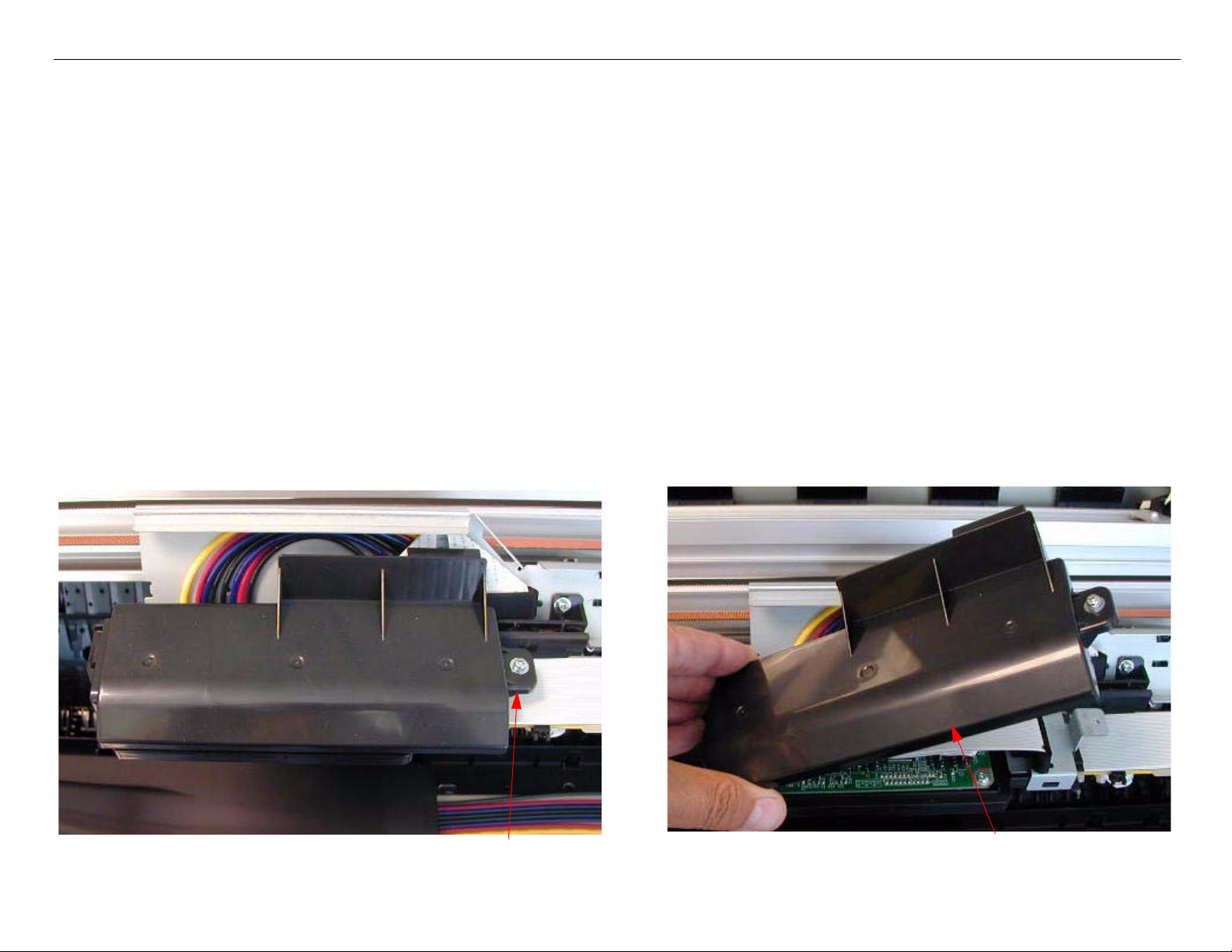
Edge Detector (EdgeAD) Replacement
1. Remove the Top Cover.
2. Release the Carriage Assembly and move the Carriage away from the capped position.
3. Remove the Carriage Board Cover and unplug the Edge Detector (EdgeAD Sensor)
2. Unplug the Edge Detector.
1. Loosen 1 Screw and remove the Carriage
Board Cover.
Edge Detector (EdgeAD) Replacement Printer Component, Software Item, LCD Display, Printer Button Page 99.
Page 100

Pro 7880 / 9880 Field Repair Guide 12/20/07
4. Remove the Cutter Assembly.
1. Remove 3 Screws.
2. Cut 1 Tie Wrap.
3. Remove the Cutter Assem-
bly, and place out of the
way.
Note: Be careful of the Ink Mark Sensor Foil Cable, it is
easy to damage or pull off the Ink Mark Sensor.
Edge Detector (EdgeAD) Replacement Printer Component, Software Item, LCD Display, Printer Button Page 100.
 Loading...