

Page 1

®
SERVICE MANUAL
Color Large Format Inkjet Printer
EPSON Stylus PRO 7500
SEIJ00005
Page 2

Notice:
n
All rights reserved. No part of this manual may be reproduced, stored in a retrieval system, or transmitted in any form or by any means, electronic, mechanical,
photocopying, recording, or otherwise, without the prior written permission of SEIKO EPSON CORPORATION.
n
The contents of this manual are subject to change without notice.
n
All efforts have been made to ensure the accuracy of the contents of this manual. However, should any errors be detected, SEIKO EP SON would greatly appre cia te
being informed of them.
n
The above not withstanding SEIKO EPSON CORPORATION can assume no responsibility for any errors in this manual or the consequences thereof.
EPSON is a registered trademark of SEIKO EPSON CORPORATION.
General Notice: Other product names used herein are for identification purpose only and may be trademarks or registered trademarks of their respective owners.
EPSON disclaims any and all rights in those marks.
Copyright © 2000 SEIKO EPSON CORPORATION. Printed in Japan.
Page 3

PRECAUTIONS
Precautionary notations throughout the text are categorized relative to 1) personal injury and 2) damage to equipment.
DANGER Signals a precaution which, if ignored, could result in serious or fatal personal injury. Great caution should be exercised in performing
procedures preceded by DANGER Headings.
WARNING Signals a precaution which, if ignored, could result in damage to equipment.
The precautionary measures itemized below should always be observed when performing repair/maintenance procedures.
DANGER
1. ALWAYS DISCONNECT THE PRODUCT FROM THE POWER SOURCE AND PERIPHERAL DEVICES PERFORMING ANY MAINTENANCE
OR REPAIR PROCEDURES.
2. NO WORK SHOULD BE PERFORMED ON THE UNIT BY PERSONS UNFAMILIAR WITH BASIC SAFETY MEASURES AS DICTATED FOR
ALL ELECTRONICS TECHNICIANS IN THEIR LINE OF WORK.
3. WHEN PERFORMING TESTING AS DICTATED WITHIN THIS MANUAL, DO NOT CONNECT THE UNIT TO A POWER SOURCE UNTIL
INSTRUCTED TO DO SO. WHEN THE POWER SUPPLY CABLE MUST BE CONNECTED, USE EXTREME CAUTION IN WORKING ON
POWER SUPPLY AND OTHER ELECTRONIC COMPONENTS.
WARNING
1. REPAIRS ON EPSON PRODUCT SHOULD BE PERFORMED ONLY BY AN EPSON CERTIFIED REPAIR TECHNICIAN.
2. MAKE CERTAIN THAT THE SOURCE VOLTAGES IS THE SAME AS THE RATED VOLTAGE, LISTED ON THE SERIAL NUMBER/RATING
PLATE. IF THE EPSON PRODUCT HAS A PRIMARY AC RATING DIFFERENT FROM AVAILABLE POWER SOURCE, DO NOT CONNECT IT
TO THE POWER SOURCE.
3. ALWAYS VERIFY THAT THE EPSON PRODUCT HAS BEEN DISCONNECTED FROM THE POWER SOURCE BEFORE REMOVING OR
REPLACING PRINTED CIRCUIT BOARDS AND/OR INDIVIDUAL CHIPS.
4. IN ORDER TO PROTECT SENSITIVE MICROPROCESSORS AND CIRCUITRY, USE STATIC DISCHARGE EQUIPMENT, SUCH AS ANTISTATIC WRIST STRAPS, WHEN ACCESSING INTERNAL COMPONENTS.
5. REPLACE MALFUNCTIONING COMPONENTS ONLY WITH THOSE COMPONENTS BY THE MANUFACTURE; INTRODUCTION OF
SECOND-SOURCE ICs OR OTHER NONAPPROVED COMPONENTS MAY DAMAGE THE PRODUCT AND VOID ANY APPLICABLE EPSON
WARRANTY.
Page 4

About This Manual
This manual describes basic functi ons, theory of electrical and mechanical
operations, maintena nce and repair procedures of EPSON EPSON Stylus PRO
7500. The instructions and procedures included herein are intended for the
experienced repai r technicians, and attention shoul d be given to th e precautions
on the preceding page.
Contents
This manual consists of six chapters and Appendix.
CHAPTER 1. PRODUCT DESCRIPTIONS
Provides a general overview and specificati ons of the product.
CHAPTER 2. OPERATING PRINCIPLES
Describes the theory of electrical and mechanical operations of the
product.
CHAPTER 3. TROUBLESHOOTING
Provides the step-by-step procedures for the troubleshooting.
CHAPTER 6. MAINTENANCE
Provides preventive maintenance procedures and the
lists of Epson-approved lubricants and adhesives
required for servicing the product.
CHAPTER 7. APPENDIX
Provides the following additional information for reference:
n Connector pin assignments
n Parts list
n Electric circuit boards components layout
n Exploded diagram
n Electrical circuit boards schematics
CHAPTER 4. DISASSEMBLY AND ASSEMBLY
Describes the step-by-step procedures for disassembling and
assembling the product.
CHAPTER 5. ADJUSTMENTS
Provides Epson-approved methods for adjustment.
Page 5

Symbols Used in This Manual
Various symbols are used throughout this manual either to provide additional
information on a specific topic or to warn of possible danger present during a
procedure or an action. Be aware of all symbols when they are used, and
always read WARNING, CAUTION or NOTE messages.
W ARNING
CAUTIO N
CHECK
PO IN T
Indicates an operating or maintenance procedure,
practice or condition that, if not strictly observe d, could
result in injury or loss of life.
Indicates an operating or maintenance procedure,
practice, or condition that, if not strictly observed,
could result in damage to, or destruction of,
equipment.
May indicate an operating or maintenance procedure,
practice or condition that is necessary to accomplish
a task efficiently. It may also provide additional
information that is related to a specific subject, or
comment on the results achieved through a previous
action.
Indicates a reassembly procedure, practice, or
condition that, if not strictly adhered to, could result
in damage to, or nonoperability of, the equipment.
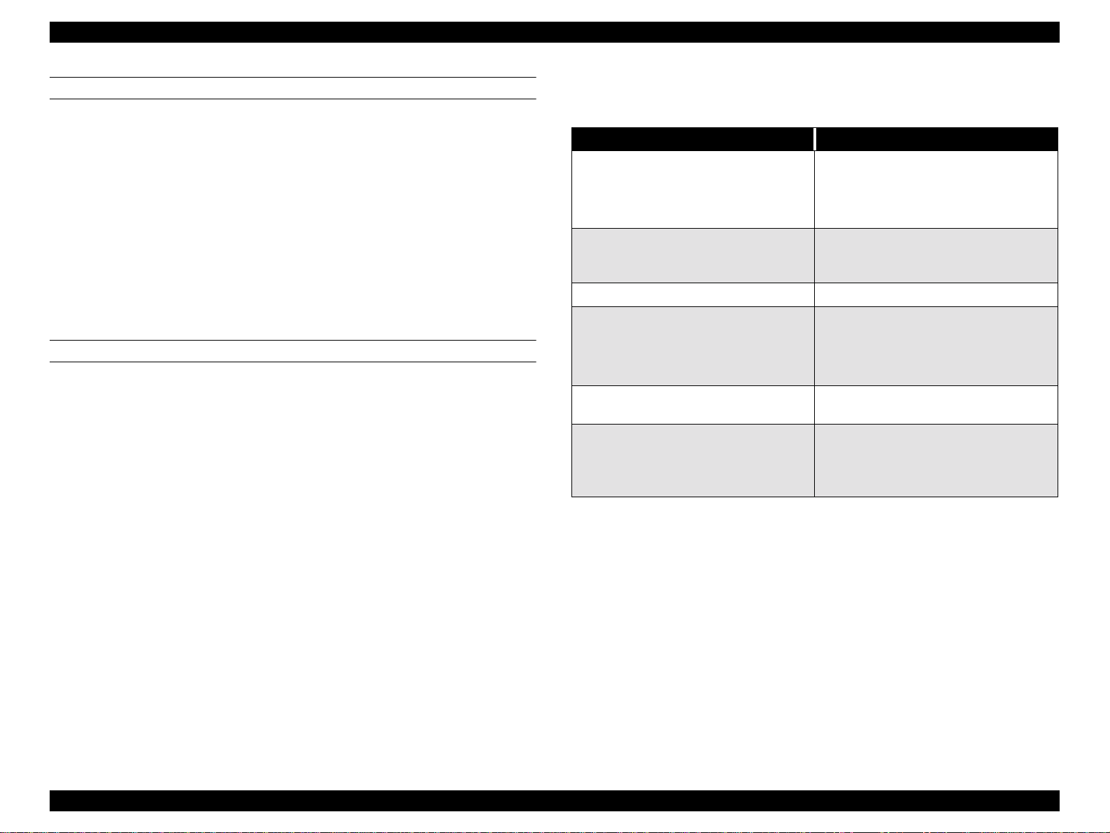
Page 6

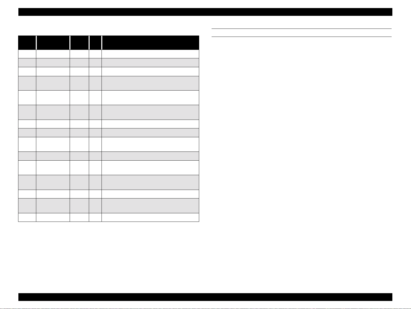
Revision Status
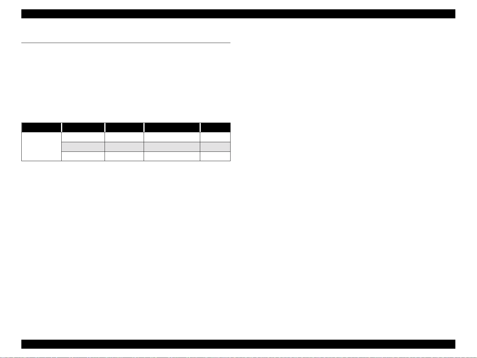
Revision Issued Date Description
Rev. A August 31, 2000 First Release
Rev. B September 7, 2000 Page 53 Ink ca rtridge size select mode can not use on SP7500.
Page 114 Dip SW setting for ASP Main bo a rd.
Page 130 Caution for the PF motor replacement
Page 172 Table 5-4 Main board replacement (Dip SW setting for ASP Mainboard)
Page 231 Dip SW setting for ASP Mainboard
Rev.C September 25,2000 Page 54 Model Name change mode
Page 163 Pigment firmware upload procedu re.
Th e pigment firmware must be uploaded before the pigment ink initial ink charge.
Page 7

Product Description
Features ....................................................................................................... 11
Consumable Products & Options............................................................ 12
Print Specifications....................................................................................... 13
Printing Specifications ...................................................................................13
Character Specifications .......................................... ...... ................................13
Paper Feeding .................................................................................................13
PAPER SPECIFICATION .............................................................................14
Ink (Dye Ink Cartridge) .................................................................................18
Electrical Specifications .................................................................................18
Conformity/Safety Approvals ........................................................................19
Reliability .......................................................................................................19
Environmental Conditions .............................................................................20
Controller Specifications ...............................................................................21
Cutting Specifications ....................................................................................21
External Dimensions / Installation Environment / Weight ............................22
Interfaces...................................................................................................... 23
Parallel Interface ........................ ...... ....... ...... ....... ...... ....... ...... ................ 23
Compatibility mode ............................................................ ...........................23
Nibble Mode ..................................................................................................26
ECP Mode ............................................... .......................................................27
USB Interface.......................................................................................... 29
TYPE-B Optional Type B Interface.......................................................... 30
Supplementary Items .............................................................................. 31
Receiving Buffer Operation ................................................ ...... ...... ...............31
Interface Selection .........................................................................................31
Initialization ................................................................................................... 31
Control Panel................................................................................................ 33
Buttons ........................................................................................................... 33
LED Indicators ...............................................................................................34
Panel Display................................................................................................ 36
Panel Setting Menu ...................................................................................... 37
Printer Setting Menus.............................................................................. 38
Test Print Menu....................................................................................... 40
Printer Status Menu................................................................................. 41
User Paper Setting Menu........................................................................ 44
Cutter Replacement Menu ...................................................................... 46
Gap Adjustment Menu............................................................................. 47
Maintenace Mode ..... ....... ............................................. ........................... 48
HEX Dump ....................................................................................................49
Panel Display Language Selection ................................................................49
M/W Mode Setting ........................................................................................49
Maintenance Mode 2............................................................................... 50
Ink Cartridge Size Select.............................................................................. 53
Inter-User Transport Mode........................................................................... 53
Firmware Reload.......................................................................................... 54
Model Name Change Mode ......................................................................... 54
Self-diagnostic Function Mode..................................................................... 55
Jumper Settings ........................................................................................... 55
Maintenance/ Service Calls.......................................................................... 56
Maintenance Call .................................................................................... 56
Service Call............................................................................................. 57
Operating Principles
Component List & Illustrations...................................................................... 59
Print Mechanism Components ..................................................................... 60
Carriage (CR) Mechanism ..................................................................... 61
Carriage Moving Unit ................................................. ...................................62
Platen Gap Adjustment Unit ..........................................................................62
Paper Feed Assembly............................................................................. 66
Cleaning Mechanism............................................................................... 68
Ink Supply Mechanism ............................................................................ 70
Other ....................................................................................................... 71
Cover Sensor ..................................................................................................71
Circuit Board Placement ................................................................................72
Control Circuit (C299MAIN Board) Outline................................................... 73
Power Supply Board Summary.................................................................... 75
Troubleshooting
Outline.......................................................................................................... 77
Introduction ............................................................................................. 77
Troubleshooting Practice ........................................................................ 78
Troubleshooting Based on Error Display...................................................... 79
Page 8

Warnings ........................................................................................................81
Errors .............................................................................................................. 81
Fatal Errors .....................................................................................................86
Errors That Require a Service Technician.................................................... 88
Maintenance Call 0100 ..................................................................................88
Service Call 00000100 ...................................................................................88
Service Call 00000101 ...................................................................................88
Service Call 00010000 ...................................................................................88
Service Call 00010001 ...................................................................................89
Service Call 00010002 ...................................................................................89
Service Call 00010003 ...................................................................................89
Service Call 00010004 ...................................................................................90
Service Call 00010005 ...................................................................................90
Service Call 00010006 ...................................................................................90
Service Call 00010007 ...................................................................................90
Service Call 00010008 ...................................................................................90
Service Call 00010009 ...................................................................................91
Service Call 0001000A ............................................................. ...... ..... ..........91
Service Call 0001000C ................................. .................................................91
Service Call 0001000D
Service Call 0001000E ..................................................................................92
Service Call 0001000F ...................................................................................92
Service Call 00010010 ...................................................................................92
Service Call 00020000 (NVRAM error)
Service Call 00020001 (Internal RAM error)
Service Call 00020002 (SRAM error)
Service Call 00020003 (DRAM error) ..........................................................92
Service Call 10000004
(CPU Vector 4 / General improper command issued)
Service Call 10000006
(CPU Vector 6 / Slot improper command)
Service Call 10000009
(CPU Vector 9 / CPU address error)
Service Call 1000000A
(CPU Vector 10 / DMAC/DTC address error)
Service Call 1000000B
(CPU Vector 11 / WD timer out error)
Service Call 10000 ** ................................................(CPU Vector 32 ~ 63) 92
Troubleshooting Based on Your Printout...................................................... 93
Dot Missing ....................................................................................................93
Uneven Printing/Poor Resolution ..................................................................94
Smudged or Marred Printout (Front) .............................................................94
Smudged or Marred Printout (Reverse side) .................................................95
White or Black Banding ................................................................................95
Disassembly & Assembly
Summary...................................................................................................... 97
Warnings................................................................................................. 97
Tools ....................................................................................................... 99
Screw List.............................................................................................. 100
Disassembly Flow ...................................................................................... 101
Removing the Housing.......................................................................... 102
Circuit Board Removal .......................................................................... 111
Removing the Cooling Fan .........................................................................112
Disconnect the AC inlet ...............................................................................112
Changing the C299MAIN Board DIP-SW Settings ....................................114
Printer Mechanism Disassembly........................................................... 115
Conversion Kit Assembly Procedure..................................................... 146
Preparation before assembly ........................................................................148
Ink Discharge Procedure ..............................................................................148
Conversion Kit Parts Replacement Procedure .............................................149
Affixing Labels ............................................................................................162
Uploading Pigment Ink Firmware ...............................................................163
Pigment Ink Initial chARGE ........................................................................164
Required Adjustment Items .........................................................................164
Bi-D Adjustment (Round Trip Alignment) .................................................165
Head Gap Adjustment (Alignment Between Heads) ................................... 167
Final Check ..................................................................................................169
Adjustment
Adjustment Outline..................................................................................... 171
Cautions................................................................................................ 171
Adjustment Tools .................................................................................. 171
Adjustment Items .................................................................................. 173
Adjustment Steps ....................................................................................... 175
Parameter Backup ................................................................................ 175
Requirements for parameter Backup ...........................................................175
Backing up parameters From Main Board to PC card .................................176
Page 9

Downloading Parameters From PC Card to new Board ..............................176
Backup/Download Error Recovery ..............................................................177
Range of Backed Up Parameters .................................................................177
Firmware Update................................................................................... 178
Updating Firmware Via the PC ....................................................................178
Updating Firmware From a Memory Card ..................................................179
Self-diagnostic Function........................................................................ 180
Version ......................................................................................................... 183
Control Panel ...............................................................................................184
Sensors .........................................................................................................184
Adjustment the Paper Sensors .....................................................................185
Encoder ........................................................................................................189
Fan ................................................................................................................189
Elec. .............................................................................................................189
Adj Cap Position ..........................................................................................194
Adj Check Skew .......................................................................................... 195
Write D/A Value ..........................................................................................196
Adj Input Rank .............................................................................................196
Adj Check Nozzle ........................................................................................197
Adj x Head Slant (B/C heads) ......................................................................198
Adj B/C Head Height ...................................................................................200
Bi-D Printing Position Adjustment ..............................................................201
Head Gap Adjustment ................................... ...............................................204
Flush Point adjustment .................................................................................205
Feed Adjustment ..........................................................................................206
Adj Top & Bottom .......................................................................................207
Adj Rear Sensor Position .............................................................................208
Test Pattern Print ..........................................................................................209
Clean Head (drain ink) .................................................................................210
Counter Clear ...............................................................................................211
"Initialize" Items ..........................................................................................213
"Update" Items .............................................................................................213
Maintenance Mode................................................................................ 215
HEX Dump ..................................................................................................216
Panel Display Language Selection ...............................................................216
M/W Mode Setting ................................. ...... ...............................................216
Maintenance Mode 2............................................................................. 217
Mechanism Adjustment......................................................................... 220
Changing the C299MAIN Board DIP-SW Settings................................ 232
Writing the USB-ID............................................................................... 233
Required Materials .......................................................................................233
Operating Environment and Preliminary Preparations ................................233
Writing the USB ID .....................................................................................233
Bi-D #4 Adjustment Check Pattern ....................................................... 235
Required Materials .......................................................................................235
Operating Environment and Preliminary Preparations ................................235
Bi-D #4 Adjustment Check Pattern .............................................................235
Maintenance
General Maintenance Issues...................................................................... 238
Periodic Maintenance Items.................................................................. 239
Product Life Information ........................................................................ 240
Important Maintenance Items During Service Operations .................... 241
Lubrication and Glue .................................................................................. 242
Appendix
Wiring Diagrams......................................................................................... 244
Parts List .................................................................................................... 246
Exploded View Diagram............................................................................. 259
Component Layout.................................. ...... ....... ...... ....... ...... ....... ...... ...... 270
Circuit Diagrams......................................................................................... 273
Page 10

PRODUCT DESCRIPTION
CHAPTER
Page 11
EPSON Stylus Pro 7500 Revision c
1.1 Features
The EPSON Stylus Pro 7500 is an 24-inch wide, 6-color ink jet printer with professional
color output. It has the same printheads as the EPSON Stylus Pro 9000. The EPSON Stylus
Pro 7500 provides the follow ing major feat ure s and mor e.
o Large Format
A1, full size
24 inch-full size printing (A1+size supported)
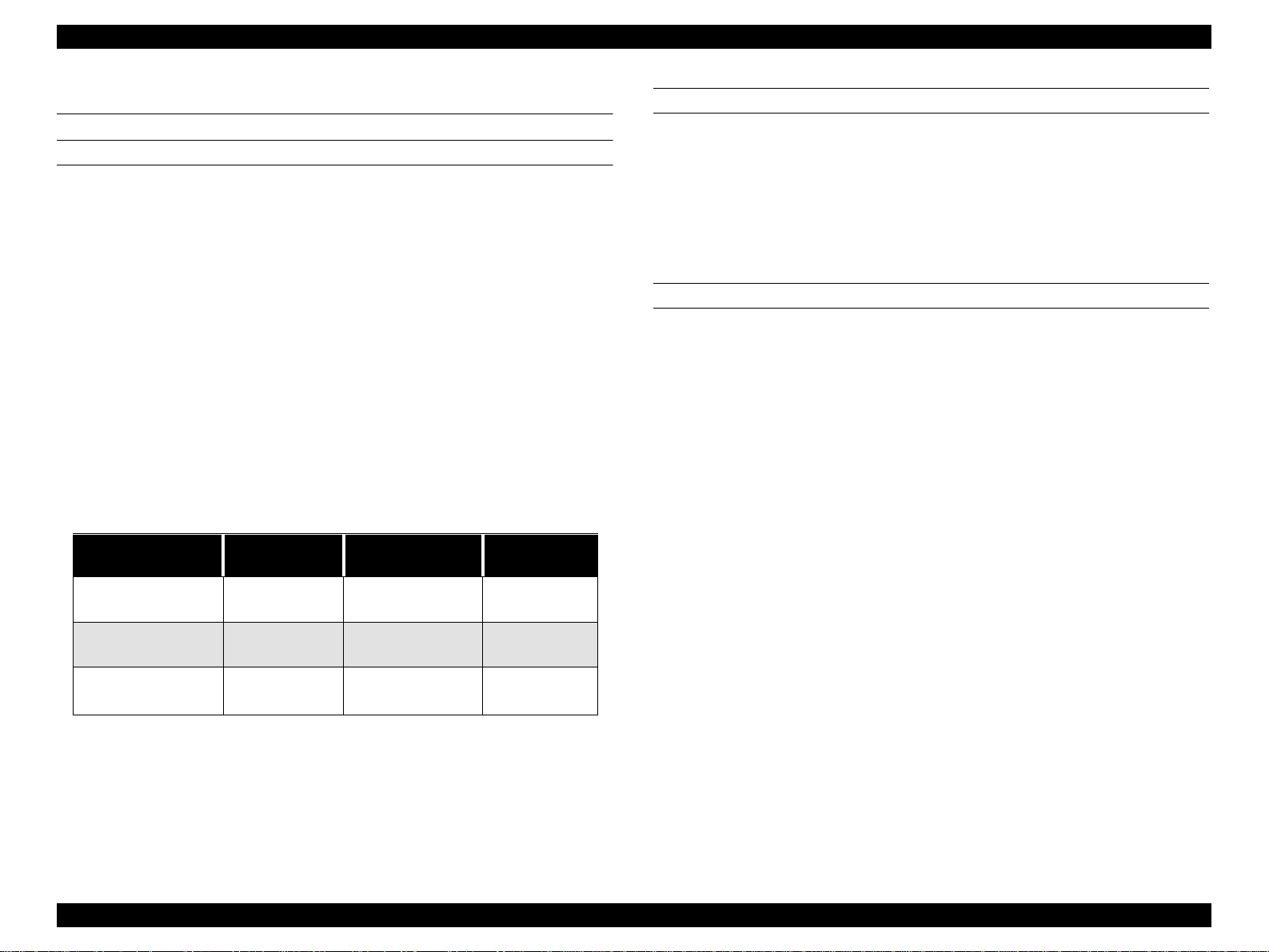
o High-speed throughput
Table 1-1.
Paper Image Quality Resolution Mode Throughput
Fast 720x720dpi Bi-D MW/MF,240cps 9min
Medium Glossy
Paper
o High Image Quality
Pigment ink in 6 colors is used. Image quality and color reproduction are at the
same level as with the Stylus Pro 9500.
Beautiful 720x720dpi Bi-D FOL,333cps 14min
High Precision 1440x720dpi Bi-D FOL,4pss, 333cps 27min
o Low running c ost
Six separate ink cartridges so you only have to replace the empty ink cartridge
(each cartridge holds 100ml of ink)
o Applicable various media
Auto cutter provided in addition to the standard roll paper feeder.
o Complete Software Compatibility With EPSON Sty lu s Pro 9000
Stylus Pro 9000 commands and Stylus Pro 7000 commands are upward
compatible and can be interchanged with the Stylus Pro 9500 commands.
o Latest RIP Technology
CPSI Pro (software)
PS Server (Scheduled to go on sale in September, 2000)
o Compact, Low in Cost
Can be used on a desktop (The stand is an option)
Product Description Features 11
Page 12

EPSON Stylus Pro 7500 Revision c
1.1.1 Consumable Products & Options
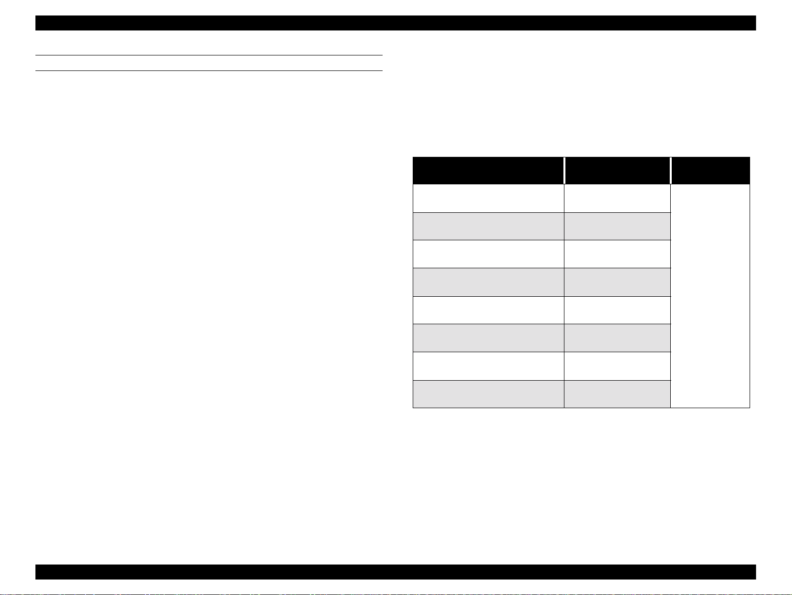
The consumables and options that can be used with the Stylus Pro 7500 are shown below.
Table 1-2. Consumables & Options
Name Code Product
T460¬¬¬
T463¬¬¬
Ink cartridges
Stand
Paper cutter blade
Roll Feed Spindle 2”
Roll Feed Spindle 3”
Doubleweight Matte Paper
Glossy Pape - PhotoW eight
Premium Glossy Photo Pap e r
Premium Semium Semig los s Phot o
Watercolor Paper - Radiant White
Glossy Film
Synthetic Paper
Adhesive Synthetic Paper
Rip Station 5100 PS Server Series
II
Software RIP (CPSI Pro) Software RIP (CPSI Pro)
T462¬¬¬
T461¬¬¬
T465¬¬¬
T464¬¬¬
C844022
C815131
C811092
C811102
S041385
S041388
S041390
S041393
S041396
S041352
S041351
S041314
S041399
S041402
EAI - C850092
Other - C850093
Black Ink
Cyan Ink
Magenta Ink
Yellow Ink
Light Cyan Ink
Light Magenta Ink
Optional stand
Consumable item
For two-inch diameter roll paper
For three-inch diameter roll paper
24 in wide/25m long
22 in wide/20m long
24 in wide/30.5m long
24 in wide/30.5m long
24 in wide/18m long
A3 Wide / B
A3 Wide / B
610mm wide/20m long
24 in wide/45m long
24 in wide/30m long
Fiery Adobe® PostScript® 3™ Server
¬ Signifies a number that varies by market.
Multi-protocol Ethernet interface
card
100Mbps Multi-protocol Ethernet
interface card
IEEE 1394 interface card
C82362¬
C82363¬
C82372¬
Type-B 10Base-T
Type-B 100Base-T
IEEE 1394 interface card
Product Description Features 12
Page 13
EPSON Stylus Pro 7500 Revision c
1.2 Print Specifications
PRINTING SPECIFICATIONS
Printing System: Ink jet
o
o Head nozzle arrangement: black = 64 nozzles (32 nozzles x 2 rows)
Color = 320 nozzles (Cyan, magenta, yellow, light cyan and light magenta, 64
nozzles each (32 nozzles x 2 rows)
o Print direction = Bi-di rection (high-speed return, high-speed skip only)
o Print Speed and Printable Area
n
Character mode
Character Quality High Quality
Character pitch 10cpi (Pica)
Printable area 237 characters
Printing speed 240cps
n
Graphic mode
See the table below.
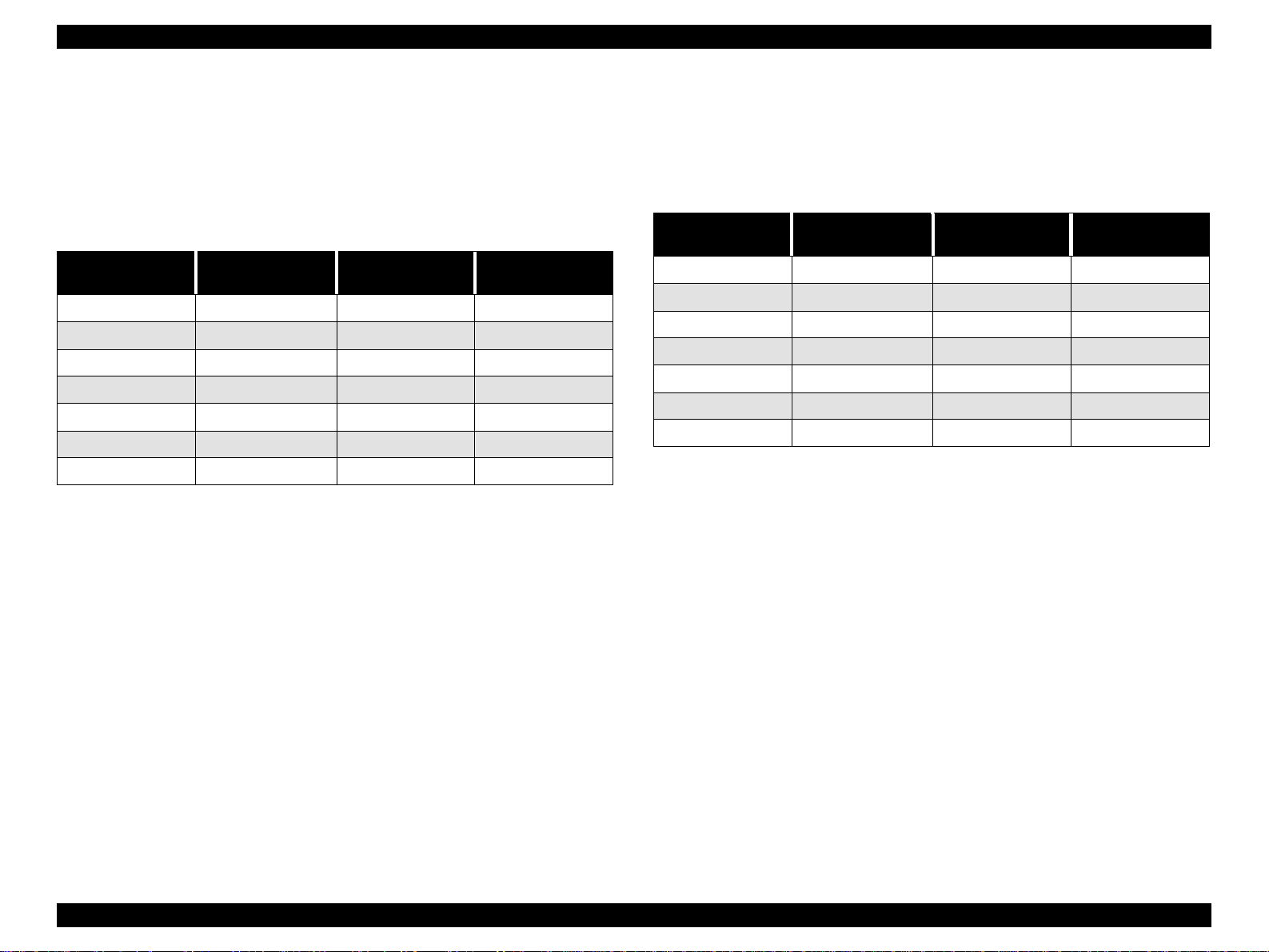
Table 1-3. Print Area and Speed
Horizontal resolution
(dpi)
360
Printable area Max. printable dots Speed
604mm
23.78 inches
8561 24 IPS
CHARACTER SPECIFICATIONS
Character Code:
o
PC437(US, Standerd Europe)
PC850(Multilingual)
o Type Faces:
Bitmap LQ fout : EPSON Courier 10 CPI
o Control Code: ESC/P Raster
PAPER FEEDING
Paper feeding method: Friction feed
Line spacing: 1/6” or programmable at 1/720”
Paper path: Roll paper/manual
±
Feed speed: 1/6” 200
Continuous 2.5” (63. 5mm ) /sec ond
10m seconds
720
1440
604mm
23.78 inches
604mm
23.78 inches
17,123
34,246
33.3 IPS/FOL
33.3 IPS/4pass
24 IPS/FOL
33.3 IPS/4pass
Product Description Print Specifications 13
Page 14
EPSON Stylus Pro 7500 Revision c
PAPER SPECIFICATION
Roll Paper: [Compatible papers]
The following papers can be loaded in this machine, but it
is not guaranteed that they will go through or that the print
quality will be good.
• Paper Size = Width: 210 ~ 610 mm
* However, it should be within the roll size.
• Roll size = 2” or 3” core
Outer diameter: within 150 mm
• Paper thickness = 0.08 ~ 0.05 mm
*1 There should be no wrin kles, fuzz, tearing or folding, of
the paper, etc.
*2 The exclusive option (3” roll paper spindle) is
necessary when using 3” core roll paper.
[Plain Paper]
Only paper feed operation is guaranteed for the following
papers.
• Paper Size = Width: 210 ~ 610 mm
* However, it should be within the roll size.
• Roll size = 2” or 3” core
Outer diameter: within 150 mm
• Paper thickness = 0.08 ~ 0.11 mm
• Paper weight = 64~90 gf/m
• Paper Quality =Plain paper, Recycled paper
*1 There should be no wrinkles, fuzz or tearing of the
paper, etc.
*2 The peel strength of the first part of the paper roll
should be within 300 ~ 500 gf.
*3 The exclusive option (3” roll paper spindle) is
necessary when using 3” core roll paper.
*4 This product should be used in a place with a normal
room temperature environment (Temperature: 15~25°C,
Relative humidity: 40~60%)
*5 The printable area for roll paper is from the core to the
point where it is cut off.
Length: 279 mm ~ 202 m
Length: 279 mm ~ 202 m
2
The remaining paper length when the paper is cut off from
the roll.
(Reference): approx. 30 cm.
[EPSON Special Paper]
The feed through characteristics and print quality of the
following genuine exclusive papers are guaranteed.
Table 1-4. EPSON Special Paper
Type (US)
Doubleweight Matte Paper
Glossy paper - Photo Wei ght
Premium Glossy Photo Paper
Premium Semigloss Photo paper
Watercolor Paper - Padiant White
Glossy Film
Synthetic Paper
Adhesive Syntheti c Paper
*1: Use at normal room te mperature (15~25°C (59~77°F) 40~60% humi dity)
*2: At the point where the rear edge comes fre e from th e core (app rox. last 3 0 cm.), pr int quality
is no longer guaranteed.
*3: The printable area for roll paper is from the core to the point where it is cut off.
The remaining paper length when the paper is cut off from the roll. (Reference): approx. 30
cm.
610mm x 25m
(24” x 83’)
559mm x 20m
(22” x66.4’)
610mm x 30.5m
(24” x 101.3’)
610mm x 30.5m
(24” x 101.3’)
610mm x 18m
(24” x 59.8’)
610mm x 20m
(24” x 66.1’)
610mm x 45m
(24” x 149.4’)
610mm x 30m
(24” x 99.6’)
Paper Size
(W x H)
Roll Size
2” core,
maximum103mm
external dia meter
Product Description Print Specifications 14
Page 15
EPSON Stylus Pro 7500 Revision c
Cut Sheet Paper: [Papers that can be loaded]
Loading of the following papers into this printer is
possible, but for papers other than the following plain
paper and exclusive paper, feed through characteristics
and print quality are not guaranteed.
• Paper Size: See the table below.
Table 1-5. Specifications of Papers which can be Loaded
Size Name
B2 515 x 728mm ????? 22” x 36”
A4 210 x 297mm ????? 20” x 24”
Super A1 24” x 36” ????? 18” x 22”
A1 594 x 841mm ANSI D 22” x 34”
A2 420 x 59 4mm ANSI C 17” x 22”
Super A3 329 x 483mm ANSI B 11” x 17”
A3 297 x 420mm Letter 8.5” x 11”
Dimensions
(H x W)
Size Name
• Paper Width: Paper length = 297 ~ 728 mm...
0.08 ~ 1.5 mm
Paper Length = 728 ~ 915 mm (36”) ...
0.08 ~ 0.5 mm
*1 There should be no wrinkles, fuzz, tearing or folding, of the paper, etc.
Dimensions
(H x W)
[Plain Paper]
For the following specifications, only the lack of
hindrance for paper feed through is guaranteed.
• Paper Size: See the table below.
Table 1-6. Specifications of Papers which can be Loaded
Size Name
B2 515 x 728mm ????? 22” x 36”
A4 210 x 297mm ????? 20” x 24”
Super A1 24” x 36” ????? 18” x 22”
A1 594 x 841mm ANSI D 22” x 34”
A2 420 x 594mm ANSI C 17” x 22”
Super A3 329 x 483mm ANSI B 11” x 17”
A3 297 x 420mm Letter 8.5” x 11”
Dimensions
(H x W)
Size Name
• Paper Thickness = 0.08 ~ 0.11 mm
• Paper Weight = 64 ~ 90 gf/m
2
• Paper Quality = Plain paper, recycled paper
*1 The paper should be loaded longitudinally.
*2 There should be no wrinkles, fuzz, or tearing, of the paper, etc.
*3 This product should be used in a place with a normal room temperature environment
(Temperature: 15~25°C, Relative humidity: 40~60%).
Dimensions
(H x W)
Product Description Print Specifications 15
Page 16
EPSON Stylus Pro 7500 Revision c
[EPSON Special Papers]
Shown below.
Table 1-7. Specifications of EPSON Special Papers
Size Name
A4 210 x 297mm ¡¡¡–
A3 297 x 420mm ¡ ¡ ¡
Super A3 329 x 483mm ¡¡¡–
A2 420 x 594mm ¡ – – –
LTR 216 x 279mm ¡¡¡–
B 279 x 432mm ¡
C 431 x 558mm ¡
B2 515 x 728mm – – – ¡
¡:Compatible Paper, –: Nonexistent Type of Paper
*1: Guaranteed for Uni-D printing.
*2: Paper that exists oversees only.
*3: The paper should be loaded long itudinally.
*4: There should be no wr inkles, fuzz or tearing of the paper, etc.
Dimensions
(H x W)
Super Fine
*1
*2
*2
Photo Print
Paper 2
*2
¡
–––
Photo
Quality
Glossy Film
*2
*2
¡
Art Board
–
–
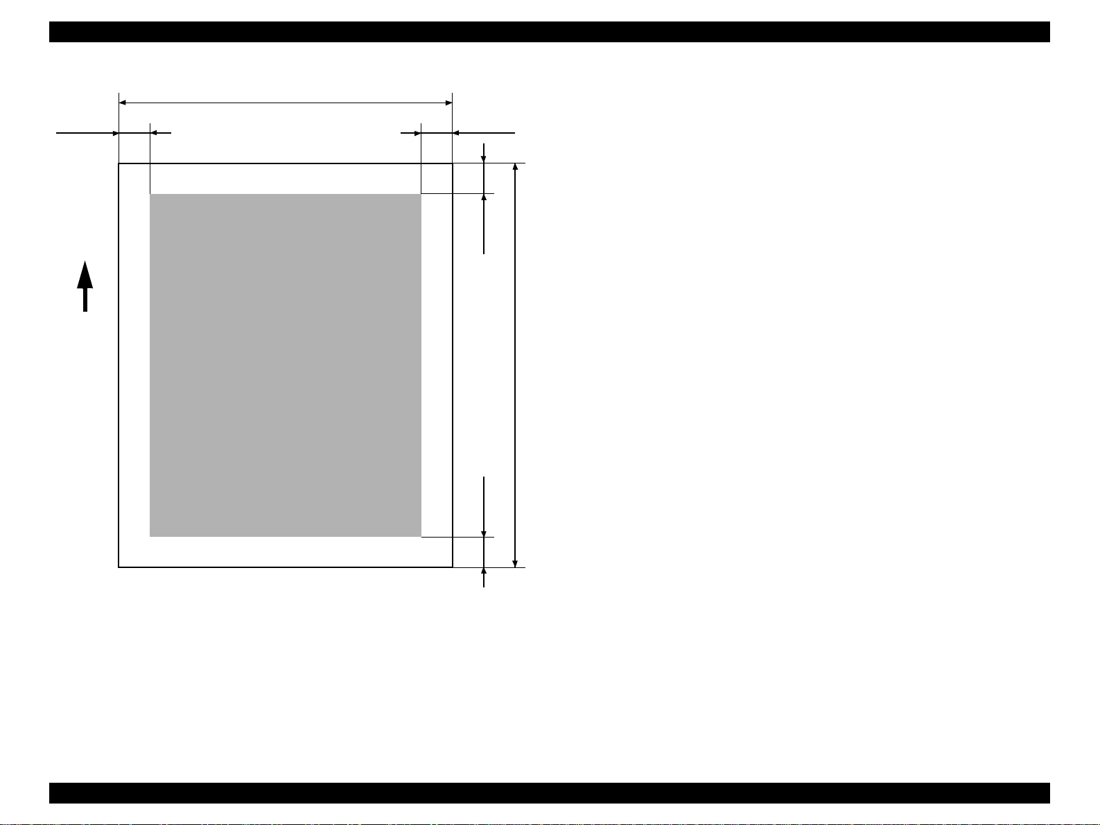
Printable Area: See the table and figure below.
Table 1-8. Printable Area
Heading Roll Paper Cut Sheets
PW (width)
PL (length)
LM (left margin)
TM (top) 3mm/15mm* 3mm
RM (right) 3mm/15mm* 3mm
BM (bottom) 3mm/15mm* 14mm
210 ~ 610mm
(8.27 ~ 24”)
Max. 90m
(298.8’)
3mm/15mm*
(0.12~0.59”)
• The printer detects the paper width when the paper is set.
• Any image that exceeds the detected paper width, or the printable area specified by
the paper size setting, is not printed.
• The size of the margin of roll paper can be changed from the panel as shown below.
Top and Bottom: 15 mm Left and Right: 3 mm / Top, Bottom, Left and Right: 3 mm
/ Top, Bottom, Left and Right: 15 mm.
210 ~ 610mm
(8.27 ~ 24”)
297~915mm
(11.8~36.4”)
3mm
*5: This product should be used in a place with a normal room temperature environment
(Temperature: 15~25°C, Relative humidity: 40~60%).
Product Description Print Specifications 16
Page 17
EPSON Stylus Pro 7500 Revision c
PW
LM
Paper
Feed
Printable Area
RM
TM
PL
BM
Figure 1-1. Printable Area
Paper Set Lever:
• By opening the paper Set lever, paper support is canceled and the paper can be set.
• By closing the paper Set lever, the set paper is held in place and printing is enabled.
• If the paper Set lever is opened during printer operation, the “SECURE PAPER
LEVER” error occurs.
Product Description Print Specifications 17
Page 18
EPSON Stylus Pro 7500 Revision c
INK (DYE INK CARTRIDGE)
Form: Exclusive Ink Cartridge
o
o Ink Colors: Black, Magenta, Light Magenta, Cyan, Light Cyan, Yellow
o Quantity: 110 ml
o Effective Ink Volume: 83.0g or more
o Life:
A1: Approx. 28 pages (720 dpi, when the printed share of the paper surface used
by each color is 40%.)
A1: Approx. 11 pages (720 dpi, when the printed share of the paper surface used
by each color is 100%.)
D Size: Approx. 26 pages (720 dpi, when the printed share of the paper surface
used by each color is 40%.)
A4: Approx. 3800 pages (360 dpi, when the printed share of the paper surface
used by each color is 5%.)
o Dimensions: 25.1 x 141.1 x 105.3 mm (Width x Depth x Height)
o Weight: Approx. 200 g
o Effective Period: Approx. 2 years from manufacture.
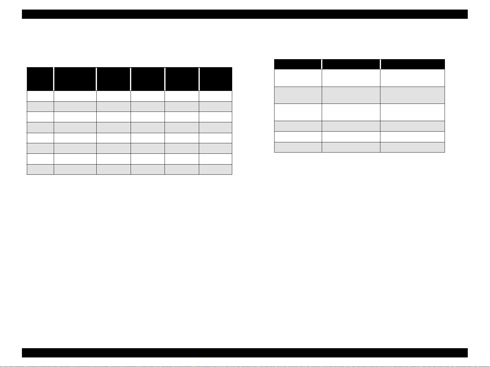
o Storage Temperature: See the table below.
.
Table 1-9. Ink Cartridge Storage Environment
Condition Temperature Cautions
ELECTRICAL SPECIFICATIONS
Table 1-10. Electrical Specifications
120V Model 220-240V Model
Rated voltage range AC120V AC220~240V
Input voltage range AC90~132V AC198~264V
Rated frequency range
Input frequency range
Rated current 1.0A (Max. 1.6A) 0.5A (Max.0.8A)
Power consumption
Insulation resistance 10MΩ minimum (between AC line and chassis, DC 500 V)
Dielectric strength
standby mode = 15W or less
Energy Star Compliant
AC 1,000V rms per minute or
AC 1,200V rms per second
(between AC line and chassis)
50~60Hz
49.5~60.5Hz
AC 1,500V rms per minute
(between AC line and chassis)
During transport
when loaded
Storage when
packed
When load ed in the
printer
-30~60°C
-30~40°C If 40°C, within 1 month
-20~40°C If 40°C, within 1 m onth
• If 60°C, within 120 hrs.
• If 40°C, within 1 month
Usable ink cartridges: For Stylus Pro 7500 100 ml Ink Cartridge
For Stylus Pro 9500 200 ml Ink Cartridge *1
NOTE: If the above ink cartridge *1) uses, it is necessary to set it according to
1.9 “Ink C artridge Siz e Select.”
Product Description Print Specifications 18
Page 19

EPSON Stylus Pro 7500 Revision c
CONFORMITY/SAFETY APPROVALS
Safety Standards:
US Model UL 1950, CSA 22.2 No. 950
European Model EN60950 (VDE)
EMC:
US Model FCC part 15 subpart B class B
CSA C108.8 class B
European Model EN 55022 (CISPR Pub. 22) class B
EN 61000-3-2
EN 61000-3-3
EN 50082-1
IEC 801-2
IEC 801-3
IEC 801-4
Australian Model AS/NZS 3548 class B
International Energy Star Compliant
(EPA MOU2.1 Category Large Format Printer)
RELIABILITY
Life
o
[Body] 20,000 Pages (A1)
[Print Head] 2 billion dots/nozzle
[Cutter] 2,000 Sheets (A1)
o Periodic Replacement Parts
Maintenance Kit, Stylus Pro 7500 (No. 1054038)
This kit consists of the following parts.
Waste ink absorbent, pump assembly, cap assembly, flushing box assembly, head
cleaner (approximately 12,000 sheets (A1, criterion)
Product Description Print Specifications 19
Page 20
EPSON Stylus Pro 7500 Revision c
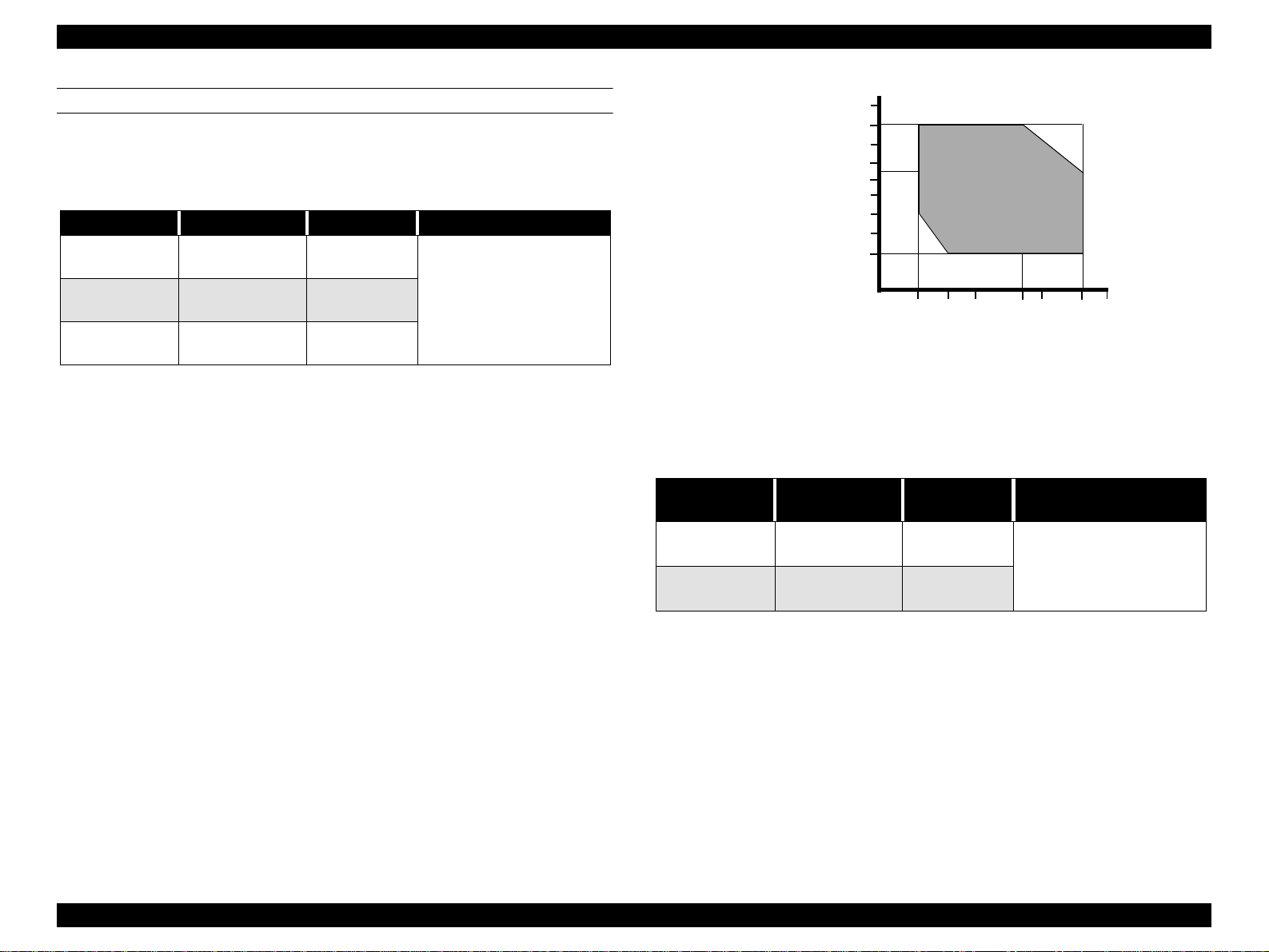
ENVIRONMENTAL CONDITIONS
Temperature&Humidity
o
See the following table.
Table 1-11. Environmental Conditions
Condition Temperature Humidity Notes
Operating
Storage
Transportation
*1 When storing the printer, make sure the printheads are in the home (capped) position. If
necessary switch power on, wait for the printheads to move to the home position, and then
switch power off.
*2 Before transporting the printer, remove the ink cartridges and turn the ink valves screws to
the closed position. Also make sure the printheads are in the home, capped, position. After
transporting the printer, install new ink cartridges.
*3 If the temperature drops below -15°C (5°F), the ink in the cartridges and printheads freezes.
The ink thaws completely after three hours at 25°C (77°F).
*4 If kept in an environment with a temperature of -15°C or lower, the ink inside the print head
and the ink cartridge will freeze. Once ink is frozen, a period of approximately 3 hours in a
25°C environment is required until the ink can be used again
10~35°C
(50~95°F)
-20~40°C
(-4~104°F)
-20~60°C
(-4~140°F)
20~80%
20~85%
5-85%
• Less than a month at 40°C
(104°F)
• Less than 120 hours at 60° C
(140°F)
• With no freezing
.
90
80
70
60
Humidity (%)
50
40
30
20
10
15
10
20
27 30 35
Temperature (°C)
Figure 1-2. Environmental Conditions: Temperature / Humidity
Vibration&Shock
o
See the following table.
Table 1-12. Vibration and Shock
Condition
Operating
Storage
Vibration
Resistance
0.15G
10~55Hz
0.5G
10~55Hz
Shock
Resistance
1G
maximum 1ms
X/Y/Z directions
2G
maximum 2ms
40
Notes
Product Description Print Specifications 20
Page 21
EPSON Stylus Pro 7500 Revision c
CONTROLLER SPECIFICATIONS
CPU
o
Hitachi SH7043 33 Mhz
o ROM
[Program]: CPU internal = 128 KB, External = 1 MB
[Fonts]: Not Loaded
o RAM
10 MB (Fixed)
o Interface
[Standard] IEEE 1284 Interface
USB Interface
Option Type B Interface Card Slot (x 1)
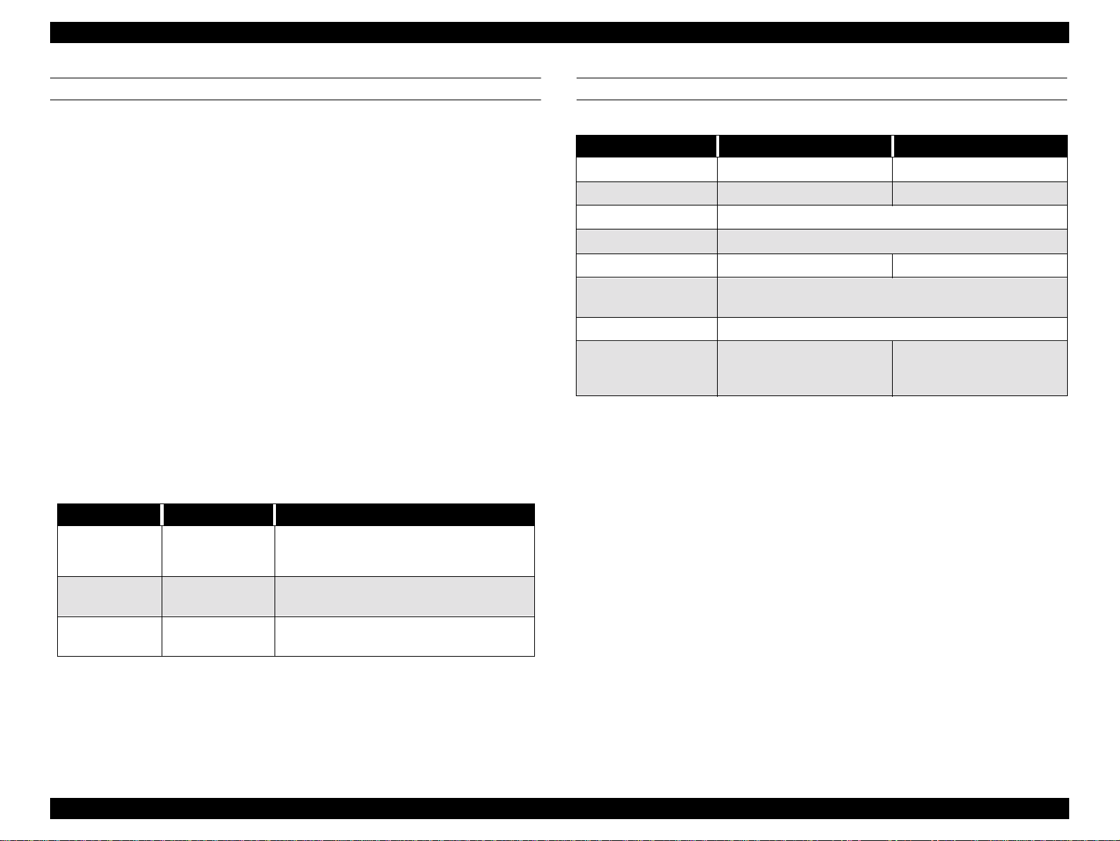
CUTTING SPECIFICATIONS
Mechanical Conditions
o
• Distance between Cutting Position and Cutter Marks
L1 = 47.5 mm
• Shortest cutting length L2 during 3-stage cutting = 100 mm
* (Paper width detection = OFF and) during manual cutting, L2 = 47.5 mm
• Shortest cutting length L3 = 20 mm
Cutting conditions and cutting system: See the table below.
Table 1-13. Cutting Conditions and Cutting System
Cutting Conditions Cutting System
Initial cut (Manual cutting when the paper is
on the top edge sensor an d the lever is down,
and the “Cut/Eject” button is pressed.)
Auto cutting after printing is finished and reset
is activated during printin g.
Manual cutting during printing. Same as above.
Manual cutting while in the normal standby
state.
Manual cutting after paper feed in the forward
paper feed direction.
Manual cutting after prin ting wit h Auto cutt ing
OFF and with Auto cutting ON.
When paper width sensor = ON.
4-stage cutting with the paper fed distance L1.
When paper width sensor = OFF.
3-stage cutting with the paper fed distance L2.
3-stage cutting. However, if (L+) is shorter
than L2, 3-stage cutting after feeding the paper
distance L2.
When paper width sensor = ON.
4-stage cutting with the paper fed distance L1.
When paper width sensor = OFF.
3-stage cutting with the paper fed distance L2.
Same as above.
If L1 + (L+) _ L2, 3-stage cutting with the
paper fed distance L1.
If L1 + (L+) < L2, 3-stage cutting with the
paper fed distance L2 – (L+).
• Let the distance the paper is pulled out from the cu t position by printing and paper
feed in the forward paper feed direction be (L+).
• Let the distance the paper is pulled back from the cut position by reverse paper
feed be (L–).
• L1 should be greater than L3.
Product Description Print Specifications 21
Page 22
EPSON Stylus Pro 7500 Revision c
Installation Environment.
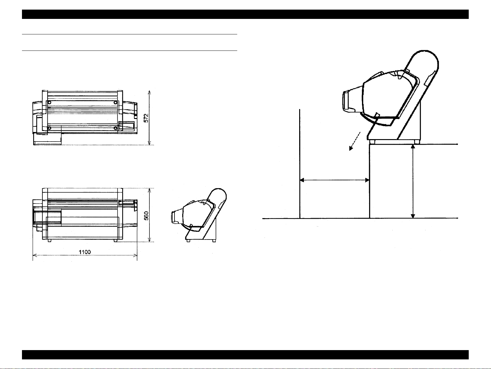
EXTERNAL DIMENSIONS / INSTALLATION ENVIRONMENT / WEIGHT
External Dimensions
o
1100 x 572 x 560 (Width x Depth x Height)
See the figure below.
o
See the figure below.
Other Obst acles
Paper Eject
Direction
Figure 1-3. External Dimensions
60 cm or more
Distance from
obstacles in front of
printer
(floor)
* Consideration should be given so that printed matter falling during paper
Eject is not damaged.
* The distance between the rubber feet on the front of the printer and the edge
of the desk should be insignificant.
60 ~ 80 cm
Height from floor.
Figure 1-4. Installation Environment
Weight
o
Approx. 43.5 kg (Not including consumables and the optional stand.
Product Description Print Specifications 22
Page 23

EPSON Stylus Pro 7500 Revision c
1.3 Interfaces
This printer is equipped with a parallel and a USB interface as standard equipment. As an
option, it can also be equipped with a Type B Interface.
1.3.1 Parallel Interface
COMPATIBILITY MODE
Data transfer format: 8-bit parallel, IEEE-1284 interchangeable
o
o Synchronization Method: External supply / by Strobe pulse.
o Handshake: By BUSY and /ACKNLG signals.
o Logic Level: TTL compatible level
(IEEE-P1284 Level 1 device)
o Applicable Connector: 57-30360 (Amphenol) 36-pin or comparable
product.
* It is recommended that the shortest possible
interface cable be used.
o Signal Arrangement and Signal Names: See the table below.
Product Description Interfaces 23
Page 24
EPSON Stylus Pro 7500 Revision c
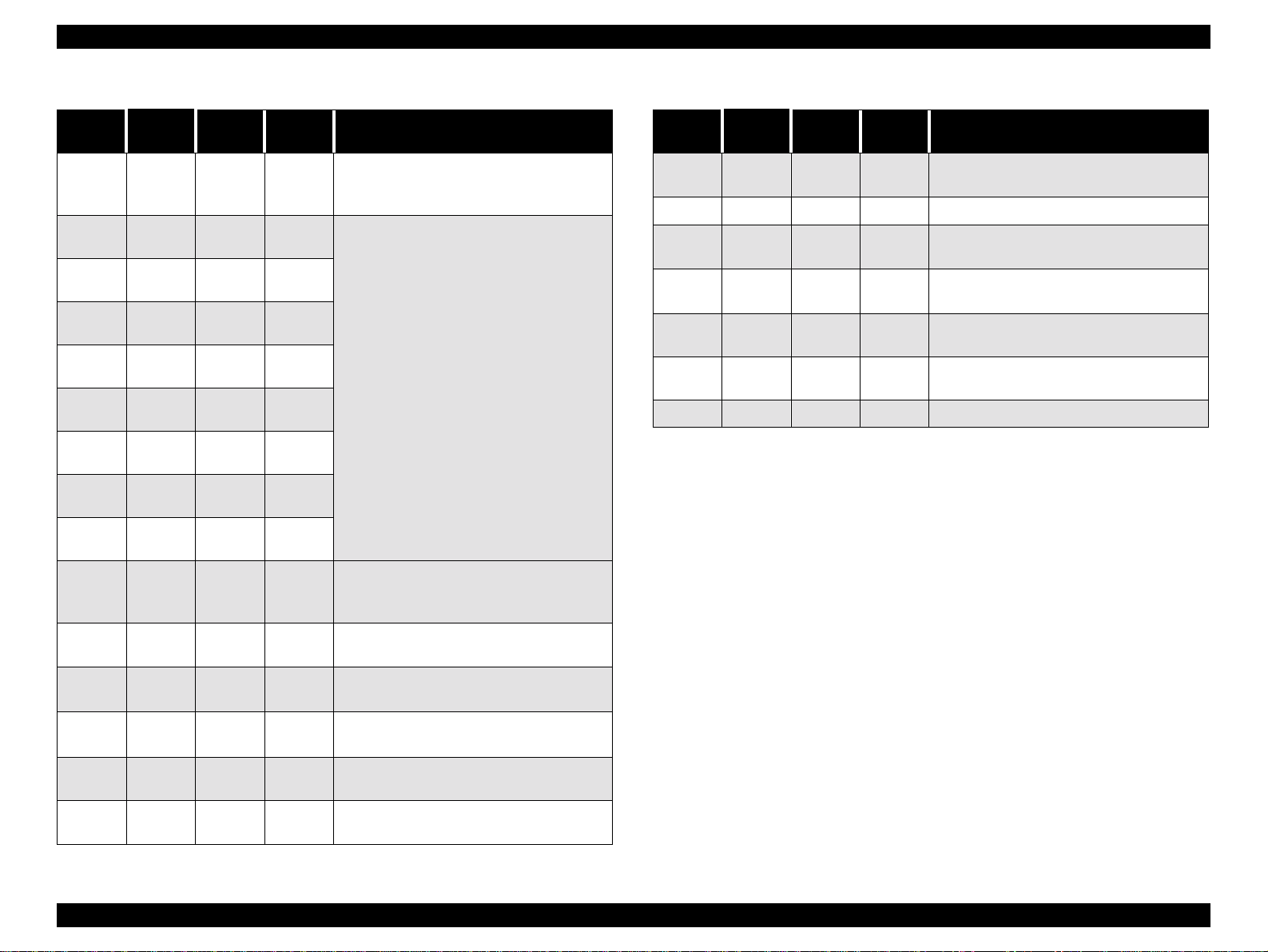
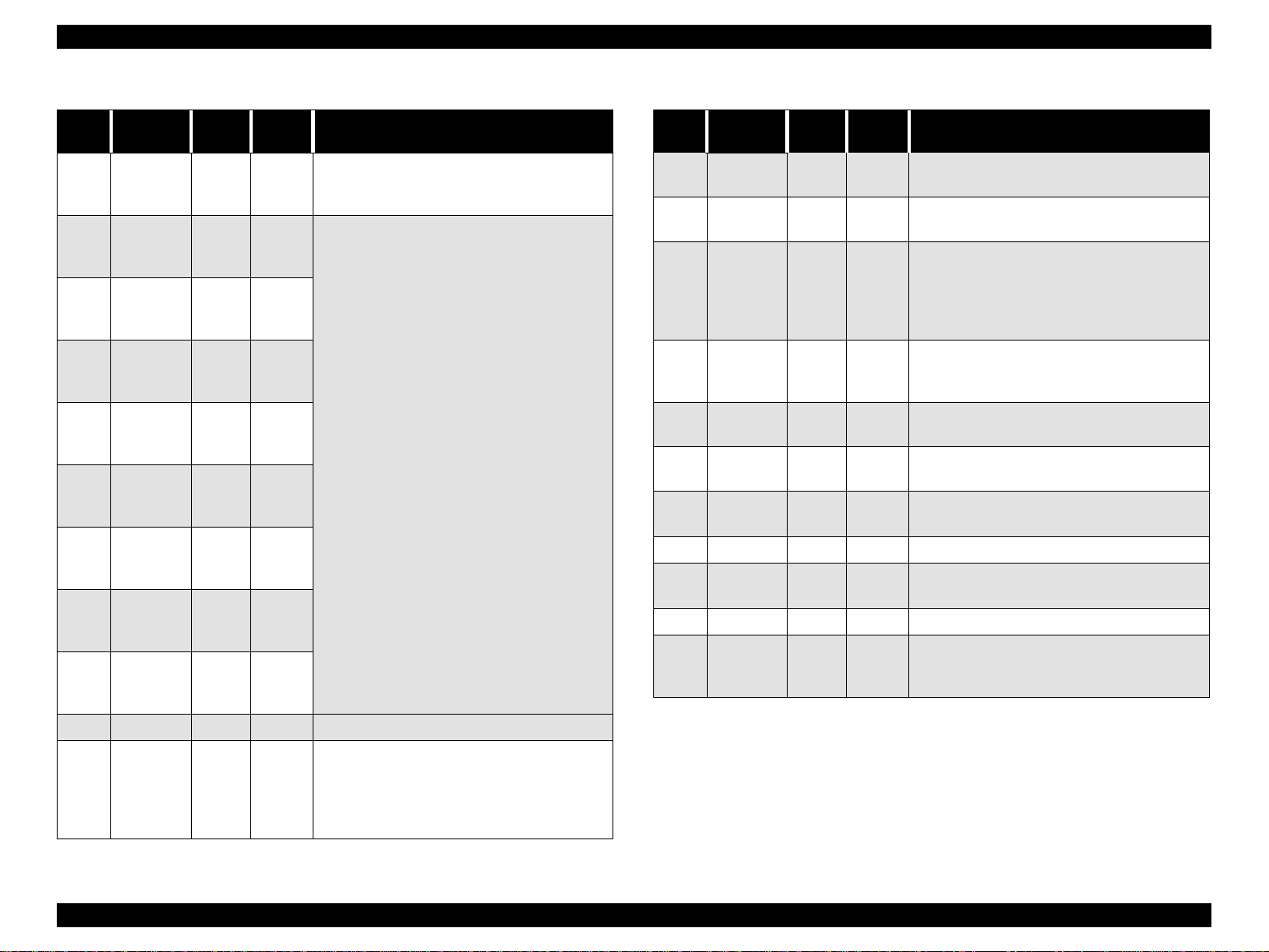
Table 1-14. Parallel Interface (Compatibility Mode)
Pin No.
1 /STROBE 19
2 DATA1 20
3 DATA2 21
4 DATA3 22
5 DATA4 23
6 DATA5 24
7 DATA6 25
8 DATA7 26
9 DATA8 27
10 /ACKNLG 28 Printer
Signal
Name
Return
Pin No.
Machine
Machine
Machine
Machine
Machine
Machine
Machine
Machine
Machine
Source Function
Center
Center
Center
Center
Center
Center
Center
Center
Center
Strobe puls e (When Low, data can be read.
When High, data cannot be received from the
PC.)
Data Signal
When Low, it indicates that data processing is
finished and preparation for reception of the
next data is completed.
Table 1-14. Parallel Interface (Compatibility Mode)
Pin No.
32 /ERROR 29
36 /SLIN 30 ----
18 Logic H ---- ----
35 +5V ---- ----
17
16,33,
19-30
15,34 NC ---- ----
Signal
Name
Chassis
GND
GND ---- ----
NOTE: If it is active in the Low state, a ” /” is included with the signal name.
Return
Pin No.
---- ----
Source Function
Center
Machine
When Low, it indicates that the printer is in an
error state.
Not used.
Normally High Level 3.9 K ohms, pulled up to
5 V.
Normally High Level 1.0 K ohms, pulled up to
5 V.
Chassis GND.
Signal GND.
Not connected.
11 BUSY 29 Printer
12 PE 28 Printer
13 SLAC 28 Printer
14 /AFXT 30
31 /INIT 30
Center
Machine
Center
Machine
When High, it indicat es th at the state is such
that data reception is impossible.
When High, it indicates that the printer has no
paper.
Normally High Level 1.0 K ohms, pulled up to
5 v.
Not used.
At a Low pulse with a pulse width of 50_ or
greater, it is set in the initialization state.
Product Description Interfaces 24
Page 25
EPSON Stylus Pro 7500 Revision c
-
*1 The return side means the twisted pair return and is conn ected to the signal grou nd level.
Furthermore, when interfacing, a twisted pair cable should definitely be used for each signal
and the return side should definitely connected. Also, use of a shielded cable and
connection to the chassis ground of the center machine and the printer, respectively are
effective countermeasures against noise.
*2 All the interface conditions are TTL level standard conditions. The rise and fall time of
each signal is 0.2 _s or less.
*3 For details on the timing of each signal, see the “Data Transmission Timing” diagram in
the figure below.
*4 There must not be any data transfer with disregard of the /ACKNLG or BUSY signals.
(Data transfer to this printer must be performed when/ACKNLG is confirmed or when
BUSY is in the “LOW” state.)
*5 If appropriate character codes are set for DATA 1~8 of the interface connector (as
opposed to “1” for GND open and “0” for short circuit), and BUSY and /STROBE are
connected, an external device is not used and a printing test can be performed, which
includes the interface circuits.
*6 The printer is in the following states when the PE signal line enters the A ssert state (“L”
Level).
• Out of paper error occurring (ST:00 ER:06 state)
• Other paper errors occurring (ST:00 ER:0E, 12, 13, 14, 15, 16 state)
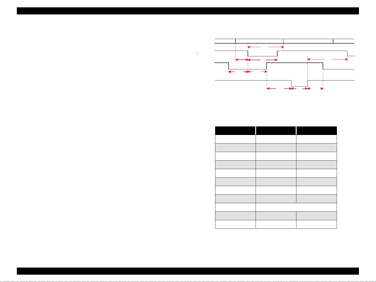
o Data Transmission Timing
DATA
STROBE
BUSY
-ACKNLG
tsetup
tready
Figure 1-5. Data Transmission Timing
Table 1-15. Timing Chart Parameter
Parameter Minimum Maximum
tsetup 500 ns thold 500 ns tstb 500 ns tready 0 -
data byte n
thold
ts tb
tbusy
tre p ly ta c k
data byte n+ 1
tnext
tnbusy
tbusy - 500 ns
tt-out* - 120 ns
tt-in** - 200 ns
treply 0 tack Typical 2 us
tnbusy 0 tnext 0 -
Product Description Interfaces 25
Page 26

EPSON Stylus Pro 7500 Revision c
NIBBLE MODE
Data Transfer Format: IEEE-1284 Nibble Mode
o
o Synchronization System: Compatible with IEEE-1284 Specifications
o Handshake: Compatible with IEEE-1284 Specifications
o Logic level: TTL level (IEE-P1284 Level 1 device)
o Data transfer timing: Compatible with IEEE-1284 Specifications
o Expansion Request Data: If the expansion request data value is 00H or 04H,
the request is received. The meanings of these
values are as shown below.
00H:Request to carry out reverse channel transfers
in the Nibble mode.
04H:Request to return the ID of the device using
the Nibble mode for reverse channel
transfers.
o Device ID: [00H] [47H]
MFG: EPSON
CMD: ESCPL2, BDC;
MDL:Stylus [SP] Pro [SP] 7500
CLS: PRINTER
DES: EPSON [SP] Stylus [SP] Pro [SP] 7500;
*: [SP] is code 20<H>.
o See the table below for the signal layout and signal names.
Product Description Interfaces 26
Page 27
EPSON Stylus Pro 7500 Revision c
Table 1-16. Parallel Interface-Nibble Mode
Pin
No.
1 HostClk 19 I Host side clock si gn a l.
2-9 Data1-8 20-27 I Data signal
10 PtrClk 28 O Printer side clock signal
11
12
13
14 HostBusy 30 I Host side BUSY signal.
31 -INIT 30 I Not used.
32
36 1284-Active 30 I 1284 Active signal.
18 Logic-H ---- O
35 +5V ---- O
Signal Name
PtrBusy/
DataBit-3,7
AckDataReq/
DataBit-2,6
Xflag/DataBit1,5
-DataAvail/
DataBit-0,4
Return
Pin
29 O
28 O
28 O
29 O
In/
Out
Printer side BUSY signal and data bit 3 or data bit
7 in the reverse channel.
ACK data request s ig na l and data bit 2 or 6 in the
reverse channel.
Xflag signal and data bit 1 or 5 in the reverse
channel.
Data available signal and data bit 0 or 4 in the
reverse channel.
Normally High Level 3.9 K ohms, pulled up to 5
V.
Normally High Level 1.0 K ohms, pulled up to 5
V.
Functional Description
ECP MODE
Data Transfer Format: IEEE-1284 ECP Mode
o
o Synchronization System: Compatible with IEEE-1284 Specifications
o Handshake: Compatible with IEEE-1284 Specifications
o Logic level: TTL level (IEE-P1284 Level 1 device)
o Data transfer timing: Compatible with IEEE-1284 Specifications
o Expansion Request Data: If the expansion request data value is 10H or 14H,
the request is received. The meanings of these
values are as shown below.
10H:Request to carry out transfers in the ECP
mode.
14H:Request to return the ID of the device using
the ECP mode.
o Device ID: [00H] [47H]
MFG: EPSON
CMD: ESCPL2, BDC;
MDL:Stylus [SP] Pro [SP] 7500
CLS: PRINTER
DES: EPSON [SP] Stylus [SP] Pro [SP] 7500;
*: [SP] is code 20<H>
o See the table below for the signal layout and signal names.
17 Chassis GND ---- ---- Printer chassis ground.
16,33,
9-30
15,34 NC ---- ---- Not used.
GND ---- ---- GND for twisted pair return.
NOTE: In (I) and Out (O) refer to the dirction of signal flow from the printer’s
point of view.
Product Description Interfaces 27
Page 28
EPSON Stylus Pro 7500 Revision c
Table 1-17. Parallel Interface (ECP Mode)
Pin
No.
1HostClk19
2 DATA1 20
3 DATA2 21
4 DATA3 22
5 DATA4 23
6 DATA5 24
7 DATA6 25
8 DATA7 26
9 DATA8 27
10 PeriphClk 28 Printer Transfers data from the printer to the host.
Signal
Name
Return
Pin
Source Function
Center
Machin
e
Center
Machin
e
Center
Machin
e
Center
Machin
e
Center
Machin
e
Center
Machin
e
Center
Machin
e
Center
Machin
e
Center
Machin
e
Transfers data or address information from the
host to the printer.
Each signal indicates parallel data information
from the first bit to the 8th bit. “HIGH” is shown
by a “1” in the data and “LOW” is shown by a “0”
in the data. These show the address from the host
to the printer or from printer to the host, or data.
Table 1-17. Parallel Interface (ECP Mode)
Pin
No.
12
13 Xflag 28 Printer
14 HostAck 30
31
32
18
35 +5V ---- Printer
17 Chassis ---- O Printer chassis ground.
16,33,
19-30
15,34 NC ---- ---- Not used.
36
NOTE: If it is active in the Low state, a ” /” is included with the signal name.
Signal
Name
nAckRever
se
nReverseR
equest
nPeriphRe
quest
PeriphLogi
c H
GND ---- ---- Ground for twisted pair return.
1284Active
Return
Pin
28 Printer
30
29 Printer This signal is used for generating host interr u pts.
29 Printer
30
Source Function
Drives the pr inter in the Low state and ap p r oves
nReverseRequest.
X-flag signal and data bit 1 or data bit 5 in the
reverse channel.
The printer uses this signal for reverse direction
Center
Machin
e
Center
Machin
e
Center
Machin
e
flow control. Also, this signal offers data bit 9,
used in judging whether the in forma tion out put in
the forward direction data signals contains
command information or data information.
Sets this signal “LOW” to switch the channel to
the reverse direction.
Normally High Level 3. 9 K ohms, pulled up to 5
V.
Normally High Level 1. 0 K ohms, pulled up to 5
V.
1284 active signal. “HIGH” while in the ECP
mode.
The printer uses this signal for forward direction
flow control. Also, this signal offers data bit 9,
11 PeriphAck 29 Printer
used in judging whether the info rmation out put in
the reverse direction data signals contains
command information or data information.
Product Description Interfaces 28
Page 29
EPSON Stylus Pro 7500 Revision c
1.3.2 USB Interface
o Standard :“Universal Serial Bus Specifications Revision
1.0”
“Universal Serial Bus Device Class Definition for
Printing Devices Version 1.0”
o Bit rate :12Mbps (Full speed device)
o Data encoding :NRZI
o Adaptable connector :USB series B
o Suggested cable length :2 meters
o Device ID <00H><4EH>
MFG: EPSON
CMD: ESCPL2, BDC
MDL: Stylus[SP] Pro[SP] 7500
CLS: PRINTER
DES: EPSON [SP] Stylus [SP] Pro [SP] 7500
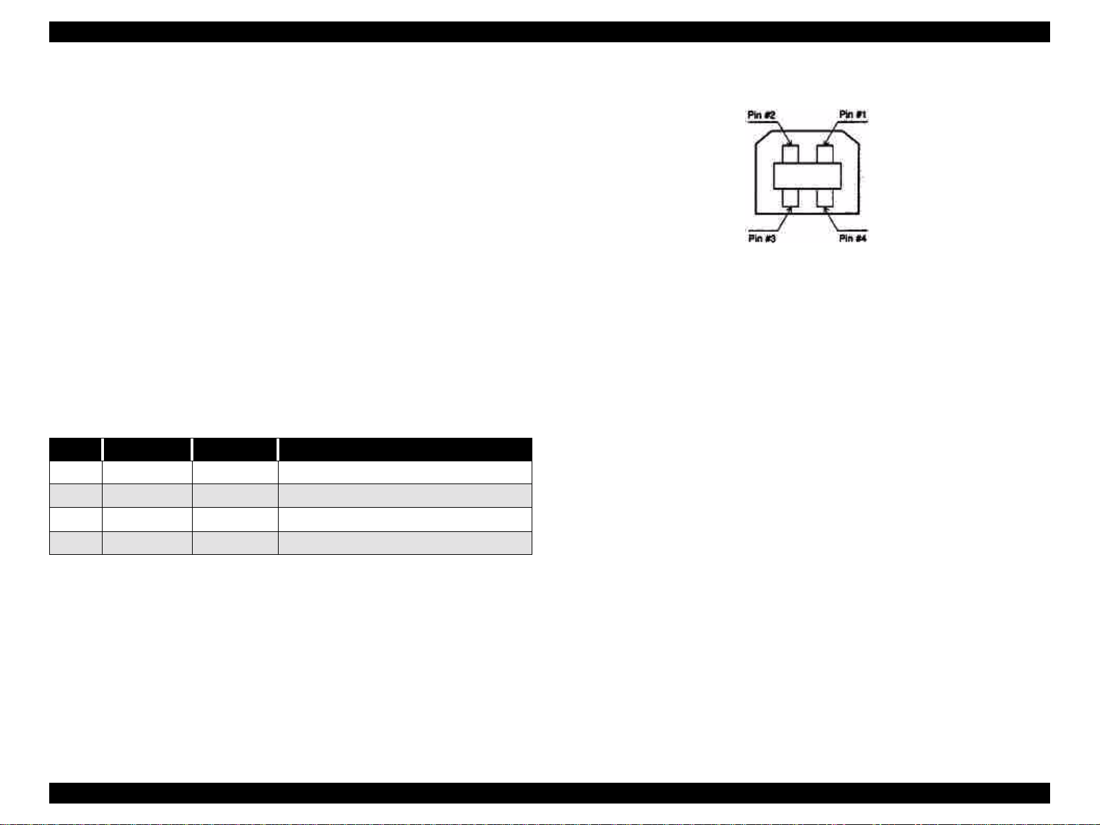
o Signal Arrangement and Signal Names: See the table below.
Table 1-18. USB Interface
Pin no. Signal name In/Out Description
1 VCC - Cable power, max. power consumption is 100mA
2 -Data bi-directional data
3 +Data bi-directional data, pull up to +3.3V via 1.5K Ω resistor
4 Ground - Cable ground
Figure 1-6. Pin Assignment
NOTE: When connecting to the USB interface, e sure to set the parallel interface
item in the printer’s settings menu on “PARA.I/F = COMPAT”
Product Description Interfaces 29
Page 30

EPSON Stylus Pro 7500 Revision c
1.3.3 TYPE-B Optional Type B Interface
o Installable Option: A Type B interface (Level 2, 1200 mA type) can be
used.
Product Description Interfaces 30
Page 31

EPSON Stylus Pro 7500 Revision c
1.3.4 Supplementary Items
RECEIVING BUFFER OPERATION
When receiving data via the parallel interface or Type B interface while in a state where no
error has occurred (including the Pause state), if the available capacity of the buffer drops to
4 KB or less, the printer receives at 1 byte/sec. and prevents the host from issuing a time
out.
If the available capacity of the buffer becomes 8 KB or higher, 1 byte/sec. reception is
canceled and reception stops when the available capacity is 32 bytes or less. When the
available capacity becomes 1K-byte or higher, reception at 1 byte/sec. is resumed.
INTERFACE SELECTION
It is possible to switch between the manual fixed selection function or auto selection
function to select the parallel, USB or optional interface.
However, if the USB interface is connected, it becomes impossible to use the parallel
interface, For this reason, only one of these interfaces, either the parallel interface or the
USB interface, can be connected to the host computer and they cannot be used in
combination.
o Manual Fixed Selection:
One interface, the Parallel/USB interface, or the optional interface, can be
selected.
o Auto Selection Function:
After the power is turned on, the interface from w hich data are first received is
selected. After that, if a predetermined period of time (fixed at 10 seconds) passes
during which the reception of data is stopped, the printer enters the idle state (a
state where no interface is selected), then selects the interface from which it first
receives data next.
o Concerning interface selection and interface state:
• When an interface other than the parallel/USB interface is selected, the parallel
interface enters the BUSY state. At this time, the LH signal goes “L.” The
meaning of LH = L is that the power is cut off. That is, it means that the 1284
interface cannot respond. Therefore, a hos t computer requesting reverse
transmission must first check LH. In addition, the USB interface is in a state where
it sends a NACK response and refuses to receive data.
• When an interface other than the optional interface is selected, the OFF-LINE bit
is set in the Main Status Register (MNSTS).
• After the printer has been initialized, or when in the idle state (with no interface
selected), with the parallel interface in the ready state, the USB interface in the
state where it does not send a NACK response, set the OFF-LINE bit of the Main
Status Register (MNSTS) for the optional interface.
• The interrupt signal, like the /INIT signal of the parallel interface, is disregarded
while that interface is not selected and while in the Nibble mode or ECP mode.
INITIALIZATION
This printer is initialized by the following three methods.
1. Hardware Initialization
This is the method of initialization that is carried out when the power is turned on.
<Initialization Operation>
• Printer mechanism initialization
• Input data buffer cleared.
• Print buffer cleared.
• Setting of default values.
2. Software Initialization
Initialization is performed by executing the Initialize command (ESC@).
<Initialization Operation>
• Print buffer cleared.
• Setting of default values.
3. Panel Initialization
This is the initialization operation when the Pause button is pressed for 2 seconds or
longer, or when the /INIT signal is input.
<Initialization Operation>
• Paper is ejected (in the case of roll paper, the printed portion is skipped and if the panel
setting’s paper select is set on Auto cut, the paper is cut, and if the cutter is OFF, the
Product Description Interfaces 31
Page 32

EPSON Stylus Pro 7500 Revision c
paper is not cut).
Print heads capped.
Input data buffer cleared.
Print buffer cleared.
Setting of default values.
4. Initial Settings
The initial settings which are set when the printer is first turned on are as shown below.
Also, as for panel settings, default settings and items which can be saved as remote
commands, the values for those items stored in memory become the default values.
Page Position:The current paper position is made the top of page position
Line Feed Amount::1/6 inch
Right Margin Positio:Column 237
Left Margin Position:Column 1
Character Pitch:10 CPI
Print Mode:Text Mode (Non-raster graphics mode)
Product Description Interfaces 32
Page 33

EPSON Stylus Pro 7500 Revision c
1.4 Control Panel
This section describes the control panel, the buttons, the lights, and the way you make
settings.
Figure 1-7. Control Panel
BUTTONS
The function of each button in the operation panel is as shown in the following table.
Table 1-19. Operation Panel Butt on Functions
Button (Operation
when pressed)
Power Turns the power on and off. – –
Pause(rESET)
SelecType
Cut/Eject (Enter)
Function (Single)
• Toggles between Print
Ready and Print Not Ready
• Reset (Press for 2 seconds.)
• Starts the panel setting
mode.
• Cutter replacement menu
(Press for 5 seconds.)
*3
• Cut sheet paper
Paper Eject.
• Roll paper auto cut
(Feeds paper from the cutter
mark to the cutter position
and cuts it.)
• Roll paper cutter OFF
(Feeds paper the height of
the head.)
Function (During panel
setting)
–
Selects Setting Menu
(Major category)
Fixes setting va lues and
stores them in memory.
Function (+
Power ON)
Starts the
Maintenance
Mode
Ink quantity
setting mode
–
Paper Feed (Paper
Feed +)
Paper Feed (Paper
Feed –)
Paper Source
(Setting Items)
Cleaning
Paper feed (Reverse) *1 Adds to the set value. –
Paper feed (Forward) *2
Selects the paper type.
Full head cleaning (press for 2
seconds).
Subtracts from the set
value.
Selects the setting item
(Minor category)
– –
–
–
Product Description Control Panel 33
Page 34

EPSON Stylus Pro 7500 Revision c
Table 1-19. Operation Panel Button Functions
Button (Operation
when pressed)
Paper Sourc e +
Eject + Paper Feed _-----
Paper Sourc e +
Eject + Cleaning
*1 For 2 seconds after the button is pressed, the paper is fed at 1.27 mm/sec. (5.0 cps). If the
button is pressed for 2 seconds longer, the paper is fed at 12.7 mm/sec. (50. 0 cps).
However, the paper can be reversed up to a maximum of 200 mm when the button is pressed
once.
*2 For 2 seconds after the button is pressed, the paper is fed at 1.27 mm/sec. (5.0 cps). If the
button is pressed for 2 seconds longer, the paper is fed at 12.7 mm/sec. (50. 0 cps).
*3 During the ink dry ing ti me, ink dryin g is inte rrupt ed and th e spec ified opera tion is perform ed.
Function (Single)
-----
Function (During pane l
setting)
Function (+
Power ON)
Starts
Maintenance
Mode 2.
Firmware
Reload Mode
LED INDICATORS
The functions of the LED’s located in the operation panel are as shown in the table below.
Table 1-20. Operation Panel LED
LED Display Status
Operate (Green)
Paper Out (Red)
Pause (Green)
Ink Out (Y) (Red)
Ink Out (LM)
(Red)
Ink Out (LC) (Red)
Ink Out (M) (Red)
Ink Out (C) (Red)
Ink Out (K) (Red)
•On
• Flashing
•On
• Flashing
•On
• Flashing
•Off
•On
• Flashing
•On
• Flashing
•On
• Flashing
•On
• Flashing
•On
• Flashing
•On
• Flashing
• Power On state, reset, timer IC reset / NVRAM Clear
• Processing data, processing power off, fatal error
• Out of paper, ro ll paper end, different roll paper/cut
sheet paper settings, cleaning impo ssible error, reset,
timer IC reset / NVRAM clear
• Paper jam, paper cutting error, p aper skew error, pape r
recognition error, cut sheet Eject failure, fatal error
• Pause state, reset timer IC reset / NVRAM clear
• Ink drying time, ink processing underway, fatal error
• Panel setting mode, pause state, other errors
• Ink out, no cartridge, reset, timer IC reset / NVRAM
clear
• Ink low (Y), fatal error
• Ink out, no cartridge, reset, timer IC reset / NVRAM
clear
• Ink low (LM), fatal error
• Ink out, no cartridge, reset, timer IC reset / NVRAM
clear
• Ink low (LC), fatal error
• Ink out, no cartridge, reset, timer IC reset / NVRAM
clear
• Ink low (M), fatal error
• Ink out, no cartridge, reset, timer IC reset / NVRAM
clear
• Ink low (C), fatal error
• Ink out, no cartridge, reset, timer IC reset / NVRAM
clear
• Ink low (K), fatal error
Product Description Control Panel 34
Page 35

EPSON Stylus Pro 7500 Revision c
Table 1-20. Operation Panel LED
LED Display Status
•On • Auto cut selected.
reset, timer IC reset/NVRAM clear
Roll Auto Cut
Roll Cutter Off
Sheet (Green)
• Flashing • Roll paper not set or roll paper and cut sheet sizes are
different.
Fatal error
•On • Cut off selected.
reset, timer IC reset/NVRAM clear
• Flashing • Roll paper not set or roll paper and cut sheet sizes are
different.
Fatal error
•On • Cut sheet paper printing mode.
reset, timer IC reset/NVRAM clear
• Flashing • Roll paper not set or roll paper and cut sheet sizes are
different.
Fatal error
Product Description Control Panel 35
Page 36

EPSON Stylus Pro 7500 Revision c
1.5 Panel Display
Messages corresponding to the printer status, error occurrence and other states are
displayed in the operation panel LCD. The messages displayed are shown in the following
table. Furthermore, the messages are shown in their display processing priority order, from
the highest priority messages to the lowest.
Table 1-21. List of Panel Display Messages
Display Content
SERVICE REQ nnnnnnnn *2 Fatal error occurrence state.
Indicates an error occurrence state that requires
MAINTENANCE REQ nnnn *3
WAIT *1
POWER OFF Executing power off processing.
INK OUT Ink out.
COVER OPEN Cover open state.
OPTION I/F ERROR A Type B interface error occurred.
TRANSPORT PREP
SECURE PAPER LEVER The paper support lever was released during operation.
LOAD xxx PAPER
maintenance by a service man (such as th e end of the
waste ink pad’s serv ice life).
Resetting the timer IC.
Clearing NVRAM.
Resetting.
Executing the ink sequence.
Executing initializatio n processing.
Processing paper initialization.
Executing ink discharge sequence for transport
between users.
The roll paper and cut sheet paper settings are
different.
Table 1-21. List of Panel Display Messages
Display Content
RELOAD PAPER
REMOVE PAPER Impossible to carry out cleaning.
NO INK CARTRIDGE The ink cartridge is not set.
PRESS PAUSE BUTTON
PAUSE Pause state (standby)
INK DRY xx MIN Ink is drying (“xx min.” = time remaining)
INK LOW
INK CHARGING nnn% Initial filling in progress *4
PRINTING *1 Processing data (printing operation in prog ress)
READY *1 Printer is ready to receive data
PAPER OUT
RESET Reset processing in progress
TURN PWR OFF AND ON
*1:If “Widen” is selected in the “Platen Gap” item in the panel settings, a “H ” is displaye d in the
20th column.
*2:See Chapter 3, “Troubleshooting”
*3: See Chapter 3, “Troubleshooting”
*4:“Initial filling in progress” displays the processing progress conditions. Initial filling ends at
the point when this value becomes 100%.
Paper Eject failed. (in the case of cut sheets)
Paper recognition error.
Waiting for the paper initialization processing start
trigger.
Remaining ink is low. (replacement preparations are
necessary)
Paper not set state
End of roll paper.
Instruction to turn the power on again. (Turn it off,
then turn it on again.)
PAPER JAM A paper jam occurred.
PAPER NOT CUT A paper cutting error with the auto cut settings.
PAPER NOT STRAIGHT Paper is being fed at a slant.
LOAD PAPER The paper support lever is released.
Product Description Panel Disp lay 36
Page 37

EPSON Stylus Pro 7500 Revision c
1.6 Panel Setting Menu
When the printer is not printing, pressing the “SelecType” button changes the pr inter to the
panel setting mode and automatically disables printing while the printer is being set. The
panel setting mode includes the fo llowing m enu items. Each time the “SelecTy pe” button is
pressed, the setting menu changes to the next menu in the sequence, which is then displayed
in the LCD.
To return to the Pause state, press the “SelecType” button until “Pause” is displayed in the
LCD panel or press the “Pause” button.
o Menu Selection: “SelecType” B utton
o Menu Item Setting: “Paper Source” Button
Mode End: “Pause” Button
Table 1-22. Panel Setting Menu Items
Menu Item Panel Display
Printer Setting Menu PRINTER SETTING MENU
Test Print Menu TEST PRINT MENU
Printer Status Menu PRINTER STATUS MENU
User Paper Sett ing Menu P AP ER CONFIG. MENU
Cutter Replacement Menu CUTTER REPLACE MENU
Gap Adjustment Menu HEAD ALIGNMENT MENU
Setting items for each of the above setting menus, with their contents, are shown below.
Product Description Panel Setting Menu 37
Page 38

EPSON Stylus Pro 7500 Revision c
1.6.1 Printer Setting Menus
In the printer setting menus, i t is possib le to chang e the s et values in th e settin g item s in the
following table. Each setting is made by operation of the following panel buttons.
o Printer setting menu selection: See the panel setting menu procedure.
o Printer setting item selection: “Paper Source” button
o Change the set value: “+” or “–” button
o Set the settings: “Enter” button
o Mode End: “Pause” button
A list of setting items in the printer setting menu is shown below.
Table 1-23. List of Setting Items in the Printer Setting Menu
Display Setting Value Contents
PLATEN GAP
PAGE LINE
INTERFACE
PARA. I/F
CODE PAGE
AUTO *1
WIDE
ON*2
OFF
AUTO *3
PARA./USB
OPTION
COMPAT
ECP
RC437*5
PC850
Adjusts the platen gap. (Ordinarily, this is done
automatically.)
While in the “Roll Paper Cutter Off” selection
state, this sets whether or not to print a cutting
line (solid line) at the bottom edge of the sheet
when the roll paper is ejected.
Interface receiving setting (Auto select or fixed
on a single interface)
Sets the parallel interface receiving rate.
(Ordinarily, it is used with the “Compatible”
setting.)
Character code set selection.
(PC437: Expanded graphics / PC850: multi-
lingual.
Table 1-23. List of Setting Items in the Printer Setting Menu
Display Setting Value Contents
PAPER SIZE CHK
PAPER ALIGN CHK
INIT. PANEL EXEC.
ON*7
OFF
ON*8
OFF
Perform / Don’t perform automatic sensing of
the paper width.
Perform / Don’t perform automatic sensing of a
paper skew error.
Returns the panel setting co nte n ts to the ir initial
values.
Sets the margin on roll paper *2
Vertical 15 mm: Leaves 15 mm on the left and
right edges of the printable area, and a 3 mm
margin at the top and bottom. / Leaves a 3 mm
margin at the top, bottom, left and right. / 15
mm: Leaves a 15 mm margin at the top, bottom,
left and right.
ROLL MAGE
T/B 15MM *6
3MM
15MM
Product Description Panel Setting Menu 38
Page 39
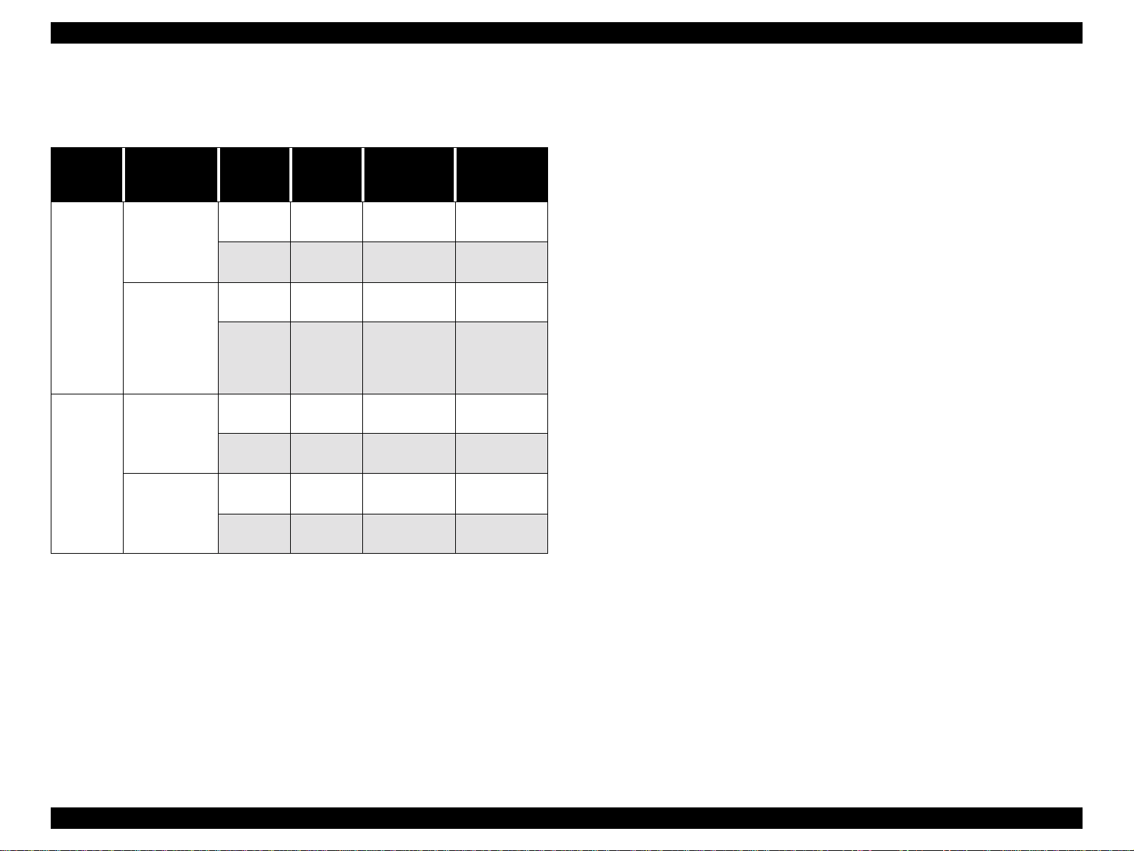
EPSON Stylus Pro 7500 Revision c
*1:By running this mode, the width of the platen gap can be set. The relationship between the
panel setting and command setting (SN command), and the actual platen gap position is as
shown below.
Table 1-24. Panel Setting Menu Items
Panel
Setting
WIDE
AUTO
Command
Setting
Platen Gap Wide
Default Platen
Gap
Platen Gap Wide
Default Platen
Gap
Paper
Width
Detector
Thick Paper Wide 2.7mm
Thin Paper Wide 2.7mm
Thick Paper Wide 2.7mm
Thin Paper Medium 2.2mm
Thick Paper Wide 2.7mm
Thin Paper Wide 2.7mm
Thick Paper Wide 2.7mm
Thin Paper Small 1.3mm
Actual PG
Position
Gap Width Use
Platen gap for
thick paper
Platen gap for
thick paper
Platen gap for
thick paper
Platen gap for
the tin paper
setting if it is
dirty
Platen gap for
thick paper
Platen gap for
thick paper
Platen gap for
thick paper
Platen gap for
thin paper
*6:Through this panel setting, switching betwe en a top, b ottom left a nd righ t roll paper m argin of
3 mm, a top, bottom, left and right margin of 15 mm and a top and bott om margin of 15 mm
and a left and right margin of 3 mm can be done. This setting is effective only with roll
paper. Cut sheet paper is no t influenced. This setting does not change the image size, but
changes the margin only.
(1)Margin Setting = 3 mm
The vertical line and horizontal pri nt ing position is the same as the logical paper size.
(2)Margin setting = 15 mm or Vertical margin setting = 15 mm
The vertical line and horizontal l in e printing position becomes 12 mm wider than the
logical paper size in the top, bottom, left and right margins or in the top and bottom
margins only.
*7:By setting the paper width sensor on OFF, occurrence of the error “set the paper correctly” is
suppressed if the paper width detection is not complete d norma lly. Printing is executed wi th
the following settings.
• The paper’s left edge position becomes the guide mark position on the paper guide.
• The printable area becomes th e pr intable area specified by the command.
If printing is being done on tracing paper, etc., which has a low reflection rate and cannot be
detected, this setting is used. Through this setting, if an image which is larger than the set
paper is printed, printing may be done on the platen, so the user must take the responsibility
for the possible consequences. (However, if detection of the top edge of the paper fai ls, it
results in an error.)
*8:If the paper skew sensor is set on “OFF,” the occurrence of t he error “Paper is skewing from
the paper feed path” is suppressed an d pri nti ng continues. By this setting, even if the printed
image overflows the edge of the paper as a result of the paper skewing from the feed path,
the printer will not inform the user of the error, so the user must take responsibility for the
possible consequenc es.
*9:By running this mode, all the value s set from the panel are returned to the default values.
*2:By running this mode, the cutting line print mode can be set. The setting contents are
equivalent to the setting for turning Print Horizontal Line ON (AC 02H 00H 00H 02H) in the
auto cutting state. The printed cutting line’s type is a solid line.
*3:By running this mode, the interface can be selected automatically, with parallel / USB or the
optional interface selected.
*4:By running this mode, the parallel interface’s operating mode can be switched to the ECP /
Compatible Mode.
*5:By running this mode, the Code Page can be switched between PC437 and PC850.
Product Description Panel Setting Menu 39
Page 40

EPSON Stylus Pro 7500 Revision c
1.6.2 Test Print Menu
In the test print menu, the test printing shown in the following table can be done. Each test
is set by operating the following panel buttons. When each test printing operation is
completed, the printer returns automatically to the Pause state.
o Test print menu selection: See the panel setting menu procedur e.
o Test Print item selection: “Paper Source” Button
Set print execution: “Enter” button
A list of the setting items in the printer setting menu is shown below.
Table 1-25. Printer Test Print M enu Setting Item List
Display Se t Value Content
NOZZLE CHECK PRINT * 1 Prints the nozzle check pattern.
STATUS CHECK Print * 2 Prints the printer setting contents.
*1: By running this mode, the head (all 6 colors) nozzle check pattern is printed and the
firmware version and waste ink counter (remainder [%]) are printed.
o Output paper size: A4
o Font used: Internal font (alphanumeric characters)
o Output Contents:
• Printer ID (= Head ID XX - XX - XX - XX - XX - XX)
In XX, the parameters IwAB-A ~ IwEF-B stored in NVRAM are printed out
in decimal numbers.
The order, from the left to right, is K - C - M - Y - Lc - Lm.
• Type B Interface Connection Condition
When installed ...... Installed
When not installed ...... None
• List of Panel Settings (including the printer status)
See the figure below.
Firmware Version )
Waste ink counter, xx: Remainder [% ])
Figure 1-8. Nozzle Check
*2: The status sheet is printed out with the following specifications.
Figure 1-9. Status Sheet
Product Description Panel Setting Menu 40
Page 41
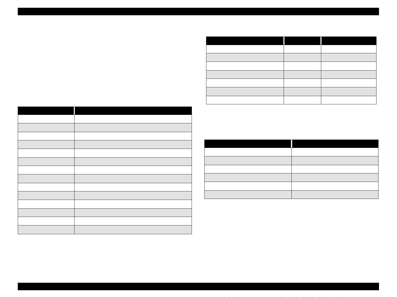
EPSON Stylus Pro 7500 Revision c
1.6.3 Printer Status Menu
The status of the status items of the printer status menu listed in the following table can be
displayed in the LCD. Ea ch type of status c an be displaye d by operatin g the following panel
buttons.
o Printer status menu selection: See the panel setting menu procedure.
o Status item selection: “Paper Source” Button
Mode End: “Pause” Button
The list of setting items in the printer status menu is shown below.
Table 1-26. List of Setting Items in the Printer Status Menu
Display Contents
VERSION Displays the firmware version (B 0 [_] [_] [_] [_] )
INK LEFT - K Displays the remaining ink level (Black) *1
INK LEFT - C Displays the remaining ink level (Cyan) *1
INK LEFT - M Displays the remaining ink level (Magenta) *1
INK LEFT - LC Displays the remaining ink level (Light Cyan) *1
INK LEFT - LM Displays the remaining ink level (Light Magenta) *1
INK LEFT - Y Displays the remaining ink level (Yellow) *1
CUTTER LIFE Displays the remaining life on the paper cutter. *2
TOTAL PRINTS Displays the cumulative total number of sheets printed.
WASTE INK Displays the waste ink counter value. *3
CR MOTER Displays the CR motor life monitor value. *4
PF MOTER Displays the PF motor life monitor value. *5
Table 1-27. Remaining Ink Counter Display List
Remaining Ink Panel Display INK End LED
100 ~ 81% remaining E ***** F Off
80 ~ 61% remainin g E **** F Off
60 ~ 41% remainin g E *** F Off
40 ~ 20% remainin g E ** F Off
20% ~ Up to just before near end E * F Off
Near end up to just before ink end n n% Flashing
Ink End 0% Lights up
*2 Calculation Method: The number of cuts is summed and calculated.
(Life (A1) = 2,000 times)
The counter is cleared by the cutte r rep lacement operation.
Display: The display is as follows.
Table 1-28. Cutter Remaining Times Counter Display List
Cutter Remaining Times Panel Display
100 ~ 81% remaining E ***** F
80 ~ 61% remaining E **** F
60 ~ 41% remaining E *** F
40 ~ 20% remaining E ** F
20% ~ 1% remaining E * F
Less than 1% remaining E F
*3 Calculation Method: The bi-directional remaining amount of main pad A/B is counted and
the smallest remainder is displayed. The display format is as shown below.
HEAD UNIT Displays the head unit life monitor value. *6
CREANER Displays the cleaning unit life monitor value. *7
*1 The remaining amount of each color of ink is displayed as follows.
Product Description Panel Setting Menu 41
Page 42

EPSON Stylus Pro 7500 Revision c
Table 1-29. Waste Ink Pad Remaining Capacity Counter Display List
Waste Ink Pad Remaining Capacity Panel Display
100 ~ 81% remaining E ***** F
80 ~ 61% remaining E **** F
60 ~ 41% remaining E *** F
40 ~ 20% remaining E ** F
20% ~ 1% remaining E * F
Less than 1% remaining E F
When the remaining capacity reaches less than 1%, the message “Maintenance Call 0100” is
generated. When the remaining capacity becomes 0, the message “Service Call 00000100” is
generated. after replacing the waste ink pad and other parts included in the Maintenance Kit
Stylus Pro 7500, clear the counter in Maintenance Mode 2.
*4:Calculation Method: The CR motor and carriag e drive mechanism are no t parts which nee d to
be replaced within the period of the product’s service life, so this item is used for
troubleshooting and preventing faults from occurring if the product is used beyond the length
of its normal service life. The life of the CR motor is virtually the same as the life of the
supply tube (when A1 paper is printed on), and it is thought that the wear and failure of the
supply tube h as an influe nce on its b reakd own , an d is there fo re s hown by t he s upp ly tu be li fe.
The supply tube’s lif e is calculated by summ ing the number of CR round trips. (Life = 4.6 x
6
times)
10
The display format is as shown below.
Table 1-30. CR Motor Life Counter Display List
CR Motor Remaining Life Panel Display
100 ~ 81% remaining E ***** F
80 ~ 61% remaining E **** F
60 ~ 41% remaining E *** F
40 ~ 20% remaining E ** F
20% ~ 1% remaining E * F
Less than 1% remaining E F
In consideration of tube damage, when the remaining life reaches 0, the error “Service Cal l
00000101” is generated. check around the ink tube, and if no damage or wear can be confirmed ,
clear the counter in Maintenance Mode 2. If damage or wear is confirmed, replace that part, then
clear the counter in Maintenance Mode 2.
*5 Calculation Method: T he PF mo to r and pap er feed driv e m ech anism are n o t parts wh ic h n eed
to be replaced within the period of the product’s service life, so this item is used for
troubleshooting. The life of the PF rollers, which wear as the PF motor operates, is shorter
than that of the PF motor, so this display shows a comparison ind ex for wear of th ese roll ers.
since the life the PF rollers is defined as the total paper feed distance (forward and reverse
directions), the total paper feed distance is summed, then the roller life calculated. (Life = 21
6
mm) The display format is as shown below.
x 10
Product Description Panel Setting Menu 42
Page 43

EPSON Stylus Pro 7500 Revision c
Table 1-31. PF Motor Life Counter Display List
PF Motor Remaining Life Panel Display
100 ~ 81% remaining E ***** F
80 ~ 61% remaining E **** F
60 ~ 41% remaining E *** F
40 ~ 20% remaining E ** F
20% ~ 1% remaining E * F
Less than 1% remaining E F
If the PF motor is repla ced, clear the counter in Maintenance Mode 2.
*6:Calculation Method: The total number of dots sprayed is summed for each color, then the
head unit’s life is calculated as the guaranteed number of dots sprayed per nozzle x 61 nozzles
and the maximum number of cumulative dots in each color is calculated. (The maximum
number of guaranteed dots sprayed per nozzle is 2 x 10⁹ dots, and the total is a value rounded
to 1000 dots for each page printed.
The display format is as shown below.
Table 1-32. Head Unit Life Counter Display List
Head Unit Remaining Life Panel Display
100 ~ 81% remaining E ***** F
80 ~ 61% remaining E **** F
60 ~ 41% remaining E *** F
Table 1-33. Cleaning Unit Life Counter Display List
Cleaning Unit Remaining Life Panel Display
100 ~ 81% remaining E ***** F
80 ~ 61% remaining E **** F
60 ~ 41% remaining E *** F
40 ~ 20% remaining E ** F
20% ~ 1% remaining E * F
Less than 1% remaining E F
After replacing the parts provided in the Maintenance Kit Stylus Pro 7500, clear the counter in
Maintenance Mode 2.
40 ~ 20% remaining E ** F
20% ~ 1% remaining E * F
Less than 1% remaining E F
If you are replacing print heads B and C, clear the counter in Maint enance Mode 2.
*7:Calculation Method: The calculation method is the same as that for the waste ink count. The
cleaning unit life is virtually the same as that of the waste ink count and it is replaced at the
same time during servicing.
The display format is as shown below.
Product Description Panel Setting Menu 43
Page 44
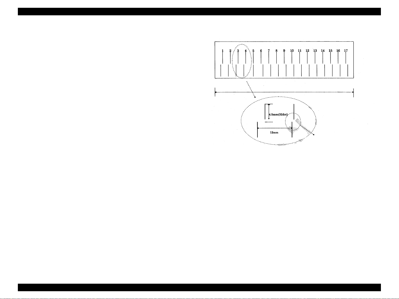
EPSON Stylus Pro 7500 Revision c
1.6.4 User Paper Setting Menu
It is possible to set the values of the following setting items in the user paper setting menu.
However, in this item, if “Standard” is selected, the following “Paper Thickness Sensing
Pattern” and “Paper Thickness No.” are not displayed. Each setting is accomplished by
operating the following panel buttons.
o User Paper Setting Menu Selection: See the Panel Setting Menu
procedure.
o User Paper Setting Item Selection: “Paper Source” Button
o Changing the Setting Value: “+” or “–” Button
o Setting the Set Value: “Enter” button
Mode End: “Pause” Button
by running this mode, the user can have the printer sense the thickness of the paper he or
she has selected and can register up to 4 types of paper as user defined paper. The ink
drying time and the suction force during suction can also be registered for each paper. the
setting method is shown below.
1) Enter the User Paper Setting Menu by the panel.
2) Select a paper type. When “Standard” is selected, proceed to (5), and when “1” ~
“4” is selected, proceed to 3).
3) Print the paper thickness sensing patterns. (See the figure below.)
Figure 1-10. Paper Thickness Sensing Patterns
The No where the gap between
the top and bottom pattern is
“0” should be selected.
4) Look at the patterns and select the number of the pattern which has the least
deviation.
5) Input the ink drying time.
6) Select the suction force (Standard / Weak).
Product Description Panel Setting Menu 44
Page 45

EPSON Stylus Pro 7500 Revision c
The user papersetting menu item list is shown below.
Table 1-34. User Paper Se tting Menu Setting Item List
Display Set Value Contents
PAPER NUMBER
THICK. PAT. PRINT *3
PAPER THICK. NO. 1~17*2
DRYING TIME 0 MIN. ~ 30 MIN.
SUCTION
*1: If “STD” is selected in the paper selection, the paper thickness sensing pattern printing and
paper thickness No. selection items are not displa y ed. The se are displaye d only if papers “1 ”
to “4” are selected. Paper setting and operations at that time are as shown in the table below.
STD
1~4 *1
NORM
LOW *4
Epson genuine pape r is used at the “Standa r d”
setting. If you are using paper with the user set
paper thickness, “1 ~ 4,” specify the relevant
No.
Prints patterns for confirming the sen sin g of th e
set paper thickness. (This item is not displayed
if “Standard” is selected for the “Pap er No. ”)
This displays a number which is the default
value for paper thickness set in the “Paper
Thickness” item in the Gap Adjus tment menu.
(0.0 mm = 1/1.6 mm = 17) (This item is not
displayed if “Standard” is selected for “Paper
No.”)
Sets the ink drying time. When auto cutting roll
paper, the printer waits the set period of time
after finishing printing.
Selects the suction force at the paper plat en.
Table 1-35. Paper Setting and Operation
Paper Setting Operation
The paper thickness is in accordance with the paper
thickness setting command (PH Command).
If the paper thickness setting command is not sent, the
STD
1 These are user registered papers.
2
3
4
*2:The paper thickness No. selection default display is the number corresponding to the paper
thickness when the gap adjustment was carried out.
*3:During print ing of the pattern, the message “PAT. PRINTING.” is displayed.
*4:By setting the suction forc e settin g on “ LOW ” the su c tion fo rce du rin g prin tin g is re duc ed by
(TBD%) when printing is carried out. In the case of extremely thin film, etc., the film will get
stuck on the platen and it may not be possible to print under the normal suction force.
printer’s default value is used.
The ink drying time is the ink drying time set by the
user except in cases where a command i s not sent.
Also, the suction force set by the user is always used
for suction.
In the case of these setting s, the paper thickness setting
command is disregarded and the paper thickness is set
by the user.
As for the ink drying time, the ink drying time set by
the user is used except in cases where the command is
not sent.
Also, the suction force set by the user is always used
for suction.
Product Description Panel Setting Menu 45
Page 46
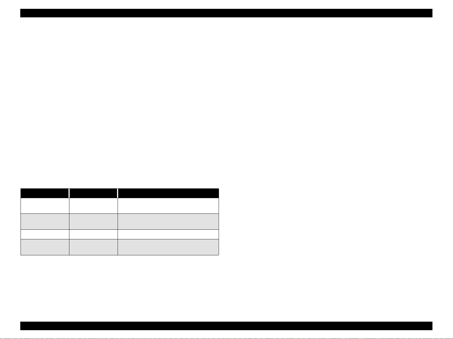
EPSON Stylus Pro 7500 Revision c
1.6.5 Cutter Replacement Menu
Replacement of the cutter is determined by the settings in the cutter replacement menu.
Each setting is made using the following panel button operations.
o Cutter Replacement Menu Selection: See the panel setting menu
procedure.
o Replacing the cutter: Paper Source button
o Changing the Setting Value: “+” or “–” button.
o Setting the Set Value: “Enter” button
Mode End: “Pause” button.
By running this mode, the cutter can be replaced. The setting method is as shown below.
1) Enter the Cutte r Replacement Menu by the panel. (You ca n also enter the cutter
replacement menu by pressing the SelecTyp e button for 5 seconds or l onger.)
2) Open the front cover.
3) Replace the cutter.
4) Close the front cover.
The cutter replacement procedure is shown in the following table.
Table 1-36. Cutter Replacement Operation Procedure
Display Setting Value Contents
CUT. REPLACE EXEC.
OPEN LOWER
COVER
REPLACE CUTTER – Cutter replacement.
CLOSE LOWER
COVER
–
–
Sets the printer in a state where it is possible to
perform the cutter replacement operation.
Open the lower cover and c arry out the
replacement operation.
Close the lower cover. That terminates the
operation.
Product Description Panel Setting Menu 46
Page 47
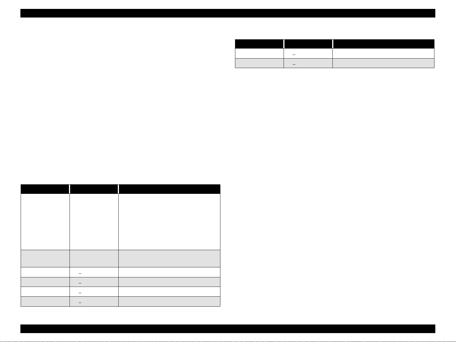
EPSON Stylus Pro 7500 Revision c
1.6.6 Gap Adjustment Menu
By running this mode, the contents of the following table are displayed and adjustment of
each item can be performed.
o Gap Adjustment Menu Selection: See the panel setting menu
procedure.
o Item Selection: Paper Source button
o Changing or Selecting Setting Values: “+” or “–” button.
o Setting the Set Value: “Enter” button
Mode End: “Pause” button.
The paper thickness setting, Bi-D, gap (adjustment of the Bi-d deviation between the left
and right heads), and printing of the adjustment pattern as well as adjustment are executed
in the gap adjustment menu.
Each setting is made by the following panel button operations. If you select the Gap
Adjustment Menu, you cannot proceed to selection of the other items without performing
the “Paper Thickness” setting. After setting the paper thickness (using the Enter butto n), the
menu automatically changes to the adjustment mode.
Table 1-37. Gap Adjustment Menu
Display Setting Value Contents
Specify the paper thickness used in the gap
adjustment in 0.1 mm units. Ordinarily, the
printer is used with the “Sta ndard” specificati on,
PAPER THICK
ADJUST. PATT.
#1 1 ~ 7
#2 1 ~ 7 ~ 15 Bi-D Adj ustment (240 cps, Normal dot, Right)
Standard or 0.0 ~ 1.6
mm
Print All
#1 ~ #6
~ 15 Bi-D Adjustment (240 cps, Normal dot, Left)
and in this case, the paper thickness becomes as
follows: Paper Thickness Detection Sensor
detection results =
If [ON / Thin Paper] : 0.2 mm
If [OFF / Thick Paper] : 1.2 mm
Specifies the gap adjustment pa ttern to be
printed. (All patterns or the desi red pattern.)
Table 1-37. Gap Adjustment Menu
Display Setting Value Contents
#5 1 ~ 7 ~ 15 Gap Adjustment 1 (240 cps, Normal dot)
#6 1 ~ 7 ~ 15 Gap Adjustment 3 (333 cps, Normal dot)
The setting method is shown below.
1) Set A1 roll paper.
2) Enter the Gap Adjustment Menu by the panel.
3) If the paper thickness is set on 0.2 mm or 1.2 mm by the panel, it is recognized as being
the same as “Standard.” If you are setting other values, input the paper thickness for the
paper you are using in 0.1 mm units, in accordance with the paper’s specifications. The
purpose for inputting the paper thickness at the first is to enable the printing of a pattern
right from the first that is thought to be close to the correction value that is already being
maintained by the printer, and thus to reduce the number of times the operation has to be
repeated.
4) Select an adjustment pattern to print (either all or individually) and print it. After
printing, the adjustment value input menu for that pattern will be displayed in the LCD.
5) Input the pattern No. for the printed pattern that has the smallest deviation in each
adjustment item displayed in the LCD.
6) Repeat steps 4) ~ 5) until adjustment of all the items has been completed.
NOTE: If you are car rying out gap a djustment printing, pri nting paper with the
following lengths is necessary.
• When selecting and printing 1 pattern: Approx. 7 cm.
• When selecting and printing all printing patterns (6 patterns): Appro x .
40 cm.
NOTE: Always, in printing of each pattern, 1 block of 15 patterns is printed 6
times. Pattern No. 8 of the 15 patterns in one block shows the current
setting value.
The correction values set by the above adjustment are saved in NVRAM. The purpose of
maintaining the paper thickness (set during the adjustment) is for the sake of making
corrections in 0.1 mm units with respect to the paper thickness from the paper thickness
setting command PH.
#3 1 ~ 7
#4 1 ~ 7 ~ 15 Bi-D Adj ustment (240 cps, Normal dot, Right)
~ 15 Bi-D Adjustment (240 cps, Normal dot, Left)
Product Description Panel Setting Menu 47
Page 48

EPSON Stylus Pro 7500 Revision c
1.6.7 Maintenace Mode
o Starting Method
While pressing the following panel button, turn the power switch On to start the
Maintenance Mode.
n
Pause button
o
Operation Method:
(1) Pressing the Paper Source button once causes you to enter the setting item
selection mode. At this time, the item at the top of the setting menu is displayed, with
the display format as follows.
[Setting Item] = [Current Setting Value] *
The “*” at the end shows that the value is the current setting value.
(2) Each time the Paper Source button is pressed, the next setting item in the sequence
is displayed in the format [Setting Item ] = [Current Setting V alue] *, with the “* ” at the
end showing that the value is the c urrent setting value.
(3) With a setting item displayed, each time the Paper Feed + button or Paper Feed –
button is pressed, the values that can be set are displayed in sequence with the format
[Setting Item] = [Current Setting Value] *. The “*” at the end is displayed only when
the displayed setting value is the current setting value.
If the Paper Feed – button is pressed, the items are displayed in reverse order. If you
continue to press the Paper Feed + button or the Paper Feed – button a predetermined
length of time, the setting values change in sequence at a predetermined interval, either
in forward sequence or reverse sequence. If you continue to press the button, after a
predetermined period of time, the display interval for the consecutive display values
will be speeded up.
(4) If the “Enter” button is pressed, the currently set value is set as the current setting
value and registered. Execution of the items accompanying this operation is also
started. However, nothing happens in the case of those items with a “*” displayed after
them already.
(5) If the SelecType button is pressed while in the Setting Item selection mode, the
printer returns to the maintenance mode display.
o End Method:
(1) to change the panel display language selection, carry out Reset after setting, then
the printer will automatically change to the ready to print state.
(2) Turn the power OFF, then ON.
o The following Maintenance Mode Setting Item List will be displayed.
Table 1-38. Maintenance Mode Setting Item List
Item Panel Display Setting Value
HEX Dump Print HEX DUMP Print *1
Panel display language selection
(for Domestic)
M/W Mode Setting MW7 A/B
*1:During HEX dump mode execution, the message “HEX MODE” is displayed.
LANGUAGE
ENGLISH, FRENCH,
ITALIAN, GERMAN,
SPANISH, PORTUGUE
Product Description Panel Setting Menu 48
Page 49

EPSON Stylus Pro 7500 Revision c
HEX DUMP
The HEX dump function is a function which prints out data transferred to the printer in
hexadecimal form. 16 data items are disp layed in HEX fo rm on a single line an d in addition,
an ASCII character corresponding to those data is printed on the right side. If there are no
characters which correspond to the data, a “.” (period) is printed for control codes, etc.
Printing of each 16 items of data is done, then finally, if the last 16 items of data remain,
printing is done by pressing the Pause button.
Furthermore, the panel settings cannot be set while the printer is in the HEX dump mode.
By using this function, you can confirm whether or not the data sent from the hos t computer
to the printer are correct.
To end this function, first stop printing by operating the Pause button, then turn the power
switch off.
PANEL DISPLAY LANGUAGE SELECTION
By running this mode, the language displayed in the LCD screen can be select English,
French, Italian, German, Spanish, Portuguese.
M/W MODE SETTING
The 720 x 720 dpi M/W operation mode can be selected from the following two choices.
o A: Operating mode that reduces banding in Bi-D printing.
o B: Stylus Pro 9000 / Stylus Pro 7000 720 dpi x 720 dpi in t e rchan geable o perat ing
mode.
When you are using the Stylus Pro 7500 to print in the monochrome(black) mode
at 720 x 720 dpi, if banding is prominent, by selecting this mode, there is a
possibility that banding will be reduced.
Product Description Panel Setting Menu 49
Page 50
EPSON Stylus Pro 7500 Revision c
1.6.8 Maintenance Mode 2
CAUTIO N
o Starting Method
While pressing the following panel buttons, turn the power switch On to start
Maintenance Mode 2.
n
The top menu of this mode consists of the following items.
Counter Display Menu VIEW COUNTERS MENU
Counter Initialization Menu CLEAR COUNTERS MENU
Adjustment, Setting Menu SERVICE CONFIG MENU
o Operation Method:
(1) By pressing the SelecType button, the screen changes to the above item
display.
(2) When the necessary item is displayed, press the Paper Source button once to
enter the display menu for that item.
The operation described here is a special function for the sake of
service support and public disclosure to the end user is prohibited.
[Paper Source Button] + [Eject Button] + [Paper Feed – Button]
Table 1-39. Maintenance Mode 2 Top Menu
Item Panel Display
[Setting Item] = [Current Setting Value] *
The “*” on the end shows that this is the current setting value.
With the setting item displayed, press the Paper Feed + button, or the Paper Feed –
Button. Each time these buttons are pressed, the settable values are displayed one at a
time in sequence with the format “[Setting Item] = [Setting Value] (*).
The values are displayed in reverse sequence when the Paper Feed – Button is pressed.
If you continue pressing the Paper Feed + Button or the Paper Feed – Button, the
setting values will be displayed at predetermined intervals in forward or reverse
sequence. If you continue to press these buttons , the values displayed will change
continuously and will become faster.
If the Enter button is pressed, the setting valu e that is currently dis played will be set as
the current setting value and registered. The items that accompany this operation will
also be started. However, nothing happens if a “*” is already displayed by the item.
(5) In the Setting Item selection mode, if the SelecType button is pressed, the printer
returns to display of Maintenance Mode 2.
o End Method:
(1) Turn the printer OFF, then ON.
n
When the Counter Display Menu is displayed.
Press the Paper Source button to switch display items.
n
When the Counter Initialization Selection menu is displayed.
Press the Paper Source button to switch display items, then press the Enter button
to carry out initialization of that item.
n
When the Adjustment Menu is selected.
By pressing the Paper Source button, change the display items and display the
necessary item. An asterisk is displayed at the end of the d isplayed setting value as
shown below.
Product Description Panel Setting Menu 50
Page 51

EPSON Stylus Pro 7500 Revision c
o
Maintenance Mode 2 Counter Display Menu Item List
Table 1-40. Maintenance Mode 2 Counter Display Menu
Item Panel Display Setting Value
Remaining Ink (K) counter Value
Display
Remaining Ink (C) counter Value
Display
Remaining Ink (M) counter Value
Display
Remaining Ink (LC) counter Value
Display
INK K
INK C
INK M
INK LC
0~42949672967295
(Decimal number)
0~42949672967295
(Decimal number)
0~42949672967295
(Decimal number)
0~42949672967295
(Decimal number)
Head Unit (LC) Service Life Counter
Value Display
Head Unit (LM) Service Life Cou nter
Value Display
Head Unit (Y) Service Life Counter
Value Display
Cleaning Unit Life Counter Value
Display
Table 1-40. Maintenance Mode 2 Counter Display Menu
Item Panel Display Setting Value
HEAD LC
HEAD LM
HEAD Y
CLEANER
0~42949672967295
(Decimal number)
0~42949672967295
(Decimal number)
0~42949672967295
(Decimal number)
0~42949672967295
(Decimal number)
Remaining Ink (LM) counter Value
Display
Remaining Ink (Y) counter Value
Display
Cutter Service Life Counter Value
Display
Total Printed Sheet Counter Value
Display
Waste Ink Counter A Value Display WAST. INK A
Waste Ink Counter B Value Display WAST. INK B
CR Motor Service Life Counter Value
Display
PF Motor Service Life Counter Value
Display
Head Unit (K) Service Life Counter
Value Display
Head Unit (C) Service Life Counter
Value Display
Head Unit (M) Service Life Counter
Value Display
INK LM
INK Y
CUTTER
TTL PAGES
CR MOTER
PF MOTER
HEAD K
HEAD C
HEAD M
0~42949672967295
(Decimal number)
0~42949672967295
(Decimal number)
0~42949672967295
(Decimal number)
0~42949672967295
(Decimal number)
0~42949672967295
(Decimal number)
0~42949672967295
(Decimal number)
0~42949672967295
(Decimal number)
0~42949672967295
(Decimal number)
0~42949672967295
(Decimal number)
0~42949672967295
(Decimal number)
0~42949672967295
(Decimal number)
Product Description Panel Setting Menu 51
Page 52

EPSON Stylus Pro 7500 Revision c
o
Counter Initialization Menu
Table 1-41. Counter Initialization Menu
Item Panel Display Setting Value
NVRAM / Timer / Service Life
Counter / Mechanism Counter
Initialization
NVRAM Initialization NVRAM INIT *2 EXEC.
Timer Initialization INIT *3 EXEC.
CR Motor Service Life Initialization INIT. CR MTR *4 EXEC.
PF Motor Service Life Initialization INIT. CR MTR *5 EXEC.
Head Unit Service Life Initialization INIT. HEAD *6 EXEC.
Cleaning Unit Service Life
Initialization
Total Printed Page count Initialization INIT. TTL PR *8 EXEC.
Ink Level Initialization INIT. INK *9 EXEC.
Waste Ink Capacity Initialization INIT. WA. INK *10 EXEC.
*1: By running this mode, the NVRAM, timer, service life counters and mechanism c ounters are
initialized.
*2: By running this mode, the NVRAM is initialized.
*3: By running this mode, the timer setting value is initialized.
*4: By running this mode, the CR motor service life counter is initialized.
*5: By running this mode, the PF motor service life co unter is initialized.
*6: By running this mode, the head unit service life counter is initialized.
*7: By running this mode, the cleaning unit service life counter is initialized.
*8: By running this mode, the total number of printed sheets counter is initialized.
*9: By running this mode, the ink level counter is initialized.
*10: By running this mode, the waste ink capacity counter is initialized.
INIT. ALL *1 EXEC.
INIT. CLEANER *7 EXEC.
o Adjustment Setting Menu
Table 1-42. Adjustment Setting Menu
Item Panel Display Setting Value
Bi-d adjustment pattern #3 offset
(333cps, Normal dot)
MW2 Balance MW7 Balance *2
*1:This sets the desi red o ffs et fo r re duci ng un eve n prin ting ( aga inst t he C R mo vem ent d irect ion )
with respect to the Bi-D adjustment value adjusted by the user. This mode is a function for
reducing irregular color that occurs in the 720 dpi x 720 dpi and 1440 dpi x 720 dpi printing
modes due to setting of the desired offset with respect to the ad justment values for Bi-D
adjustment values (Bi-D adjustment pattern No. #3) for these printing mod es. However, since
there are cases where there is no effect even when the desired offset is set in this function,
adequate caution should be exercised when changing the setting values
2 : This function is to improve the micro banding whic h may appe ar in the 720dp i x360
dpi, or 720dpi x 720dpi mode. Changing this setting value, the micro banding may be
improved a little.
desired offset is set in this function, ad equa te c autio n should be exe rc ised whe n ch ang ing the
setting values
However, since there are cases where there is no effect even when the
Bi-d offset *1
-4 - 0 - +4
-31 - 0 -+31
Product Description Panel Setting Menu 52
Page 53

EPSON Stylus Pro 7500 Revision c
1.7 Ink Cartridge Size Select
.
CAUTIO N
This setting is diplayed in this Cartridge size select mode on the latest
firmware. But, even if the 200ml Ink cartridge is set in this mode and
the 200ml ink cartridge is equipped in the product by cutting the ink
cartridge distinction rib on the cartridge, the firmware may not work
correctly. So. do not use this mode on the Stylus PRO 7500.
In the next chance of the firmware version up, this mode will be
deleted.
1.8 Inter-User Transport Mode
This is a mode to discharge the ink that the printer is filled with and make it possible to
transport the printer. It is necessary for the user to perform the following operations before
transporting the printer and make it possible for the printer to be transported.
(1) At a time when the printer’s power is turned on,. the ink cartridges of each color
should be removed.
(2) Turn the printer’s power off.
(At this time, the printer will execute the ink discharge sequence for transport
automatically. The message “TRANSPORT PREP n n %” will be displayed, and the [n
n %] will indicate the progress condition.)
*1: The paper support lever should be in the returned position and the power should be
turned Off. (When the paper support lever is in the backward state, even if the power is
turned Off, the sequence of discharging the ink for transport is not performed.)
*2: If the “Inter-user Transport Mode” ends with out any trou ble, the “Initial Filling ” flag is
set (the same state as when the printer was shipped from the factory). When the printer is
refilled with ink, the same operation as the initial filling operation should be carried out.
Product Description Ink Cartridge Size Select 53
Page 54
EPSON Stylus Pro 7500 Revision c
1.9 Firmware Reload
CAUTIO N
This writes this printer’s firmware to the Flash RO M on the M AIN board. If the main b oard
has had to be replaced due to repairs, or when upgrading the firmware version, reload the
firmware in accordance with the explanation on “5.2.2 Reloading Firmware.”
The operation described here is a special function for the sake of
service support and public disclosure to the end user is prohibited.
1.10 Model Name Change Mode
This mode starts if the power switch is turned ON while pressing the following panel
buttons.
n
[Select Type Button] + [Paper Feed – Button]
In this mode, the model name can be changed with following model name.
n
Stylus PRO 9500, MC-7000, MC-9000
Every enter this mode with above pan el operatio n, the model na me is chan ged a nd
displayed on LCD for about 2 seconds. After taking off the above button, the model
changed name is available.
CAUTIO N
n This mode is not used in the service activity basically.
So, do not use this mode.
n When you use this mode in the special case and the Type-B I/F is
used on the product, cut off the power supply to the Type-B I/F
for a while by pulling out the AC outlet before this operation.
Otherwise, the model name is not changed.
Product Description Firmware Reload 54
Page 55
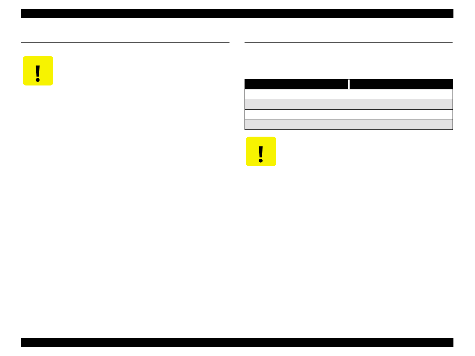
EPSON Stylus Pro 7500 Revision c
1.11 Self-diagnostic Function Mode
CAUTIO N
The self-diagnostic function mode starts if the power switch is turned ON while pressing
the following panel buttons.
n
This mode is used primarily in adjustment operations, etc. when making repairs
accompanying parts replacement. For details, see “5.2.3.2 Self-Diagnostic Mode Menus”.
The operation described here is a special function for the sake of
service support and public disclosure to the end user is prohibited.
[Setting Value + Button] + [Setting Value – Button] + [Enter button]
1.12 Jumper Settings
The standard settings for the jumpers/DIP-Switch es on the m ain b oard (C2 99M AI N) are as
shown below.
Table 1-43. Jumper Settings
No. Setting
JP1 Short
JP2 Short
SWD1 1 ON
SWD1 2 OFF
n
CAUTIO N
The above jumper settings are used only when making settings at
the factory. they should not be changed during servicing. These
jumper settings determine matching between the firmware, CPU
and ASIC, etc., so if they are changed needlessly, the printer will
not operate.
n
When installing the ASP board, the DIP-Switch settings should be
changed as shown below.
• DIP Switch Setting DIP SW1DIP SW2
• ASP Board OFF OFF
•When Circuit Board is InstalledON OFF
Product Description Self-diagnostic Function Mode 55
Page 56

EPSON Stylus Pro 7500 Revision c
1.13 Maintenance/ Service Calls
There are two types of errors which it is necessary for a service man to check and respond
to, as shown below.
• Maintenance Call n n n n
• Service Call n n n n n n n n
CAUTIO N
The maintenance and service calls explained here are special functions
for service and support, and public disclosure to the end user is
prohibited.
1.13.1 Maintenance Call
Some of the mechanical units used in this printer have counters which count down the
remaining service life based on the proper service life for each unit, and when the
predetermined value is reached, a “Maintenance Call nnnn” message is displayed. If this
message is displayed, it indicates that the end of the service life of the affected unit is
nearing, so it is necessary to replace the affected unit as soon as possible.
If this message is displayed, the “Print?” or “Printing” display message is replaced with the
“Maintenance Call nnnn” message, and after replacing the affected part, it is not cleared
but continues to be displayed until the counter is cleared.
Table 1-44. Maintenance Call / Code List
Error Code Error Content
o Waste ink pad service life (less than 1% of capacity
0100
remaining) (for treatment, see concerning the procedure
when the previously mentioned “Service Call” is issued.)
Product Description Maintenance/ Service Calls 56
Page 57
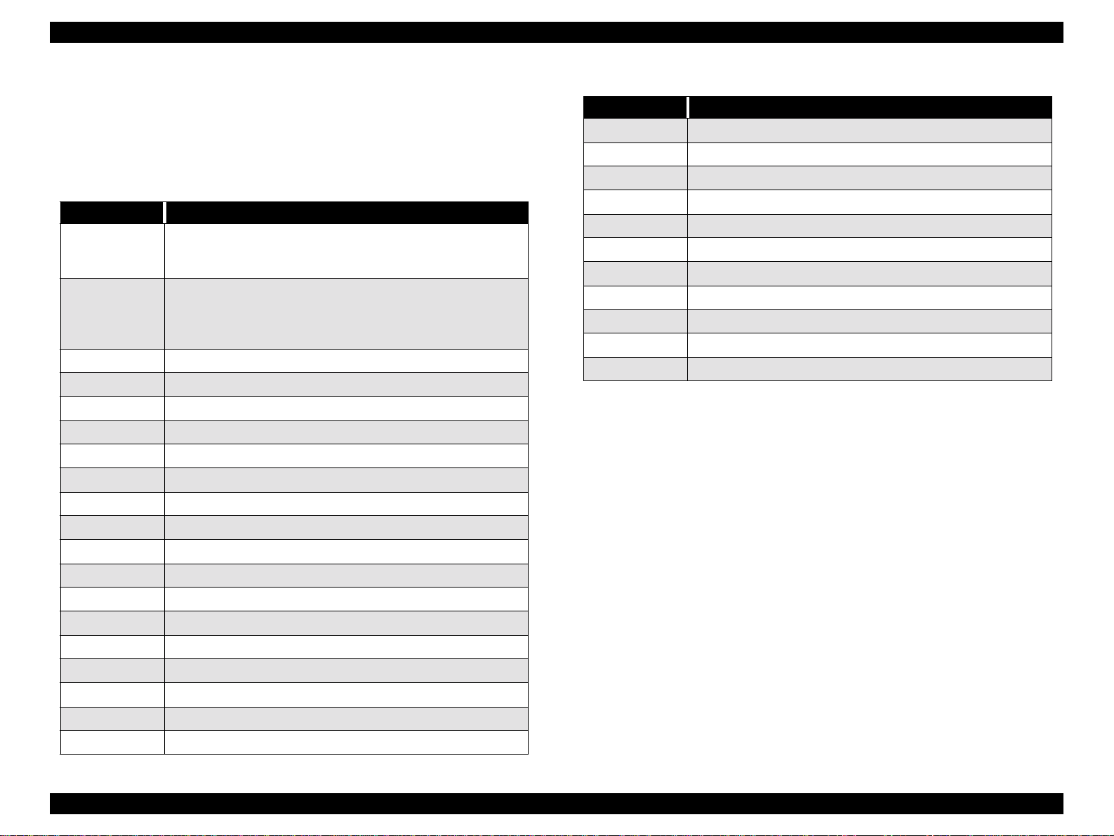
EPSON Stylus Pro 7500 Revision c
1.13.2 Service Call
If an error occurs for which service is required, the message “Service Call nnnnnnnn” is
displayed in the panel LCD and the pr inter’s operatio n stops. T he error co de correspond ing
to the content of the error that was detected is displayed in the nnnnnnnn portion of the
message.
Table 1-45. Service Call / Error Code List
Error Code Error Content
Waste ink pad serv ice life *1
00000100
00000101
00010000 PF Motor/ encoder check error
00010001 PF Moto r / Motor out of synch
00010002 PF Motor / Overcurrent
00010003 PF Motor / In Position Time Out
00010004 CR Motor / Encoder check error
00010005 CR Motor / Motor out of synch
00010006 CR Motor / Overcurrent
00010007 CR Motor / In Position Time Out
00010008 Servo interrupt WD time out error
00010009 System interrupt WD time out error
0001000A CR home position sensor failure
0001000B PF home position sensor f ailure
(Replacement of the specified part and clearing of the counter are
necessary.)
Ink supply tube wear *2
(This is equivalent to using the printer beyond the product’s service
life, so an error is displayed in consideration of damage due to ink
supply tube wear.)
Table 1-45. Service Call / Error Code List
Error Code Error Content
00020000 NVRAM error
00020001 Internal RAM Check Error
00020002 SRAM Check Error
00020003 DRAM Check Error
0002000B Mail BOX or acquisition failure
10000004 CPU Vector 4 / General improper command issued.
10000006 CPU Vector 6 / Slot improper command
10000006 CPU Vector 9 / CPU ad dr ess error
1000000A CPU Vector 10 / DMAC / DTC address error
1000000B CPU Vector 11 / WD time out error
100000** CPU Vector 32 ~ 63 I llegal trap
*1:The following parts shou ld be replaced and the relevant service life counter cleared by
“Maintenance Mode 2.”
[Parts Needing Replacement]
- Waste ink pad ( Left and right)
- F box R
- Pump assembly
- Cap assembly
- Cleaner, head
[Counters to Clear] (Clear them in “Maintenance Mode 2.)
- “Waste Ink Initialization”
- “Cleaning Initialization”
Furthermore, a periodic replacement part s kit containing these parts as a set, “Maintenance
Kit Stylus Pro 7500 (No. 1054038) ” is available.
*2:After replacing all the ink tubes (6 tubes) and the CR motor, reset the CR motor counter in
“Maintenance Mode 2.”
0001000C Head s li de (SLID) home positio n sensor failure
0001000D Cover sensor failure (00)
0001000E Cover sensor failure (01)
0001000F CR Motor / PWM output abnormal
00010010 PF Motor / PWM output abnormal
Product Description Maintenance/ Service Calls 57
Page 58

OPERATING PRINCIPLES
CHAPTER
Page 59

EPSON Stylus Pro 7500 Revision c
2.1 Component List & Illustrations
This section explains the print mechanism and operating principles for the EPSON Stylus
Pro 7500.
Operating Principles Component List & Illustrations 59
Page 60
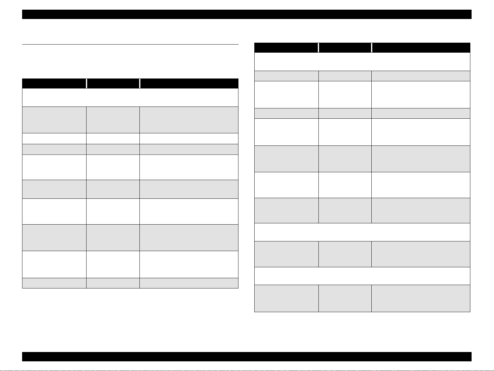
EPSON Stylus Pro 7500 Revision c
2.2 Print Mechanism Comp onents
The major electrical parts used in the printer mechanism of this printer are as shown below.
Hereafter, we will explain each printer mechanism focusing on these parts.
Table 2-1. Printer Mechanism Components
Part Drive voltage Description
Carriage components
B printhead
C printhead
Head thermistor +5VDC One in each printhead, B and C
CR motor +42VDC DC motor
CR_HP sensor + 5VDC
CR encoder sensor +5VDC
Pump motor
(PG adjustment)
PG (HD_SLID) se nsor +5VDC
P_Edge sensor +5VDC
Cutter solenoid +28VDC solenoid, cutter drive
+42VDC,
+28VDC,
-2VDC
+42VDC,
+5VDC
B/C/M printhead,
LC/LM/Y printhead
Photo interrupter
active= CR out of HP
interrupted = CR in HP
Linear encoder
two channel A phase/B phase
4 phase 200 cycle HB type stepping
motor with internal encoder sensor
-also used for cleaning
Photo reflector
reflected = in PG HP
unreflected = out of PG HP
Photo reflector
over threshold = paper exists
under threshold = no paper
Table 2-1. Printer Mechanism Components (continued)
Part Drive voltage Description
Paper feed components
PF motor +42VDC DC Servo mot or
Rotary encoder
PF encoder sensor +5VDC
Paper suction fans (x2) +28VDC DC motor fan
P_Front sensor +5VDC
P_Rear sensor +5VDC
P_Thick sensor +5VDC
Paper set lever position
sensor
Pump motor
(cleaning)
I/C sensors
(B/C/M/lc/lm/Y)
+5VDC
Ink delivery compon ents
+42VDC,
+5VDC
Clwaing components
+5VDC
two channel A phase/B phase
in PF motor
Photo reflector
over threshold = pape r e xists
under threshol d = no paper
Photo reflector
over threshold = pape r e xists
under threshol d = no paper
Photo interrupter
active= thick paper
interrupted = normal paper
Photo interrupter
active= thick paper
interrupted = normal paper
4 phase 200 cycle HB type stepping
motor with internal encoder sensor
also used for PG adjustment
Microswitch 1/ slot
Open = no I/C
Closed = I/C installed
Operating Principles Print Mechanism Components 60
Page 61
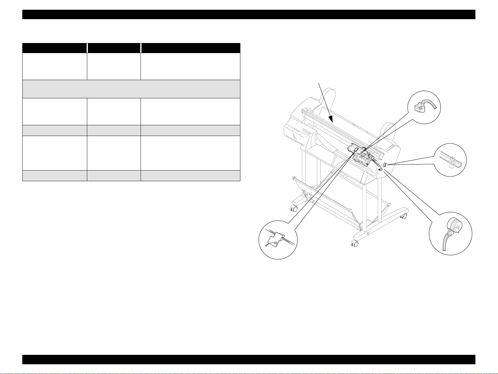
EPSON Stylus Pro 7500 Revision c
Table 2-1. Printer Mechanism Components (continued)
Part Drive voltage Description
Ink end sensors
(B/C/M/lc/lm/Y)
Cover open sensor
Panel unit
C299MAIN board
Power supply board
+5VDC
Other components
+5VDC
+5VDC
+42VDC,
+28VDC,
+5VDC,
-2VDC
-
Mechanical switch 1/ slot
Open = near end
Closed = ink remains
Mechanical switch
Open = cover open
Closed = cover closed
Printer control/drive circuit board
2.2.1 Carriage (CR) Mechanism
This printer is equipped with a unique carriage mechanism to enable movement and
printing with stable, high precision on-carriage heads in the A1 extended paper (24 inch)
width printi ng range (= carriage movement range).
Carrigee
P-Edge sensor
CR_HP Sensor and Flag
Encoder Sensor and
Timing Fence
HD-SLID Sensor and
Slide Bear
Figure 2-1. Carriage Mechanism
Operating Principles Print Mechanism Components 61
Page 62

EPSON Stylus Pro 7500 Revision c
CARRIAGE MOVING UNIT
IIn place of the carriage holding system in which 2 CR guide shafts extending in the column
direction were used, as in the previous models, a structure with the carriage mounted via
multiple rollers (bearings) on a CR guide rail made from a square extruded aluminum pipe
is used. Steel rails are incorporated in the roller contact and running surface, and the result
is a reduction in friction in the direction of movement, reduced vibration and improved
durability.
NOTE: The screws used to fasten the CR guide rail should not be taken out and
the carriage should not be remo ved. These are adj usted and as sembled to
the nearest 1/100 mm at the factory.
A DC motor is used for the CR motor and the slit in the timing fence affixed on the bottom
of and parallel with the CR guide rail is read by the encoder sensor mounted on the carriage
(linear encoder system), and this signal is compared to logical control values in the control
circuit on the C299 MAIN board , which carries out feedback speed control. Through this
control, high print precision is maintained.
Drive transmissions from the CR motor to the carriage use the easy-to-maintain, durable
timing belt.
The sensors used in the carriage moving unit are described below.
o CR_HP Sensor
This is a transmissi ve pho tose nsor which is moun ted o n the ri ght end of t he pri nter
mechanism and detects the entry position of the flag (projection) provided on the
carriage as the carriage moving home position. Outputs from this sensor are
“OFF” in the HP range and “ON” outside the HP range.
o Linear Encoder
This encoder is mounted on the back of the carriage and outputs pulses (2
channels) corresponding to the position of the slit on the timing fence that is
incorporated into the CR guide rail which are used for C R motor servo co ntrol and
PTS (Print Timing Signal) generation. The resolution is 1/180 inch.
CR Guide Rail (projected
area)
CR_HP Sensor
(Mounted on the
mechanism’s right
end.)
Encoder Sensor
(On Carriage)
CR Motor
Outside HP range Inside HP Range
Step Ruler
(Slitted Plate)
Encoder Sensor
CR Timing Belt
Carriage
HP Flag
CR_HP
Sensor
Figure 2-2. Carriage Mechanism Unit, Carriage Moving Unit
PLATEN GAP ADJUSTMENT UNIT
In order to maintain the print precision, it is necessary to maintain the carriage (= head)
mounting position so that it is always a constant distance from the surface of the paper.
In this printer, the print head nozzle surfaces and platen surface are variable mechanisms so
that the gap between the paper printing surface and the head nozzle surface can be kept
constant.
The carriage has a 2-body construction with a sub-carriage on which the print heads are
mounted attached to the carriage which forms the base. The sub-carriage moves in the
vertical direction with respect to the paper surface. This movable system uses a cam. The
sub-carriage to paper surface distance changes linearly from the cam (= PG) home position.
Operating Principles Print Mechanism Components 62
Page 63
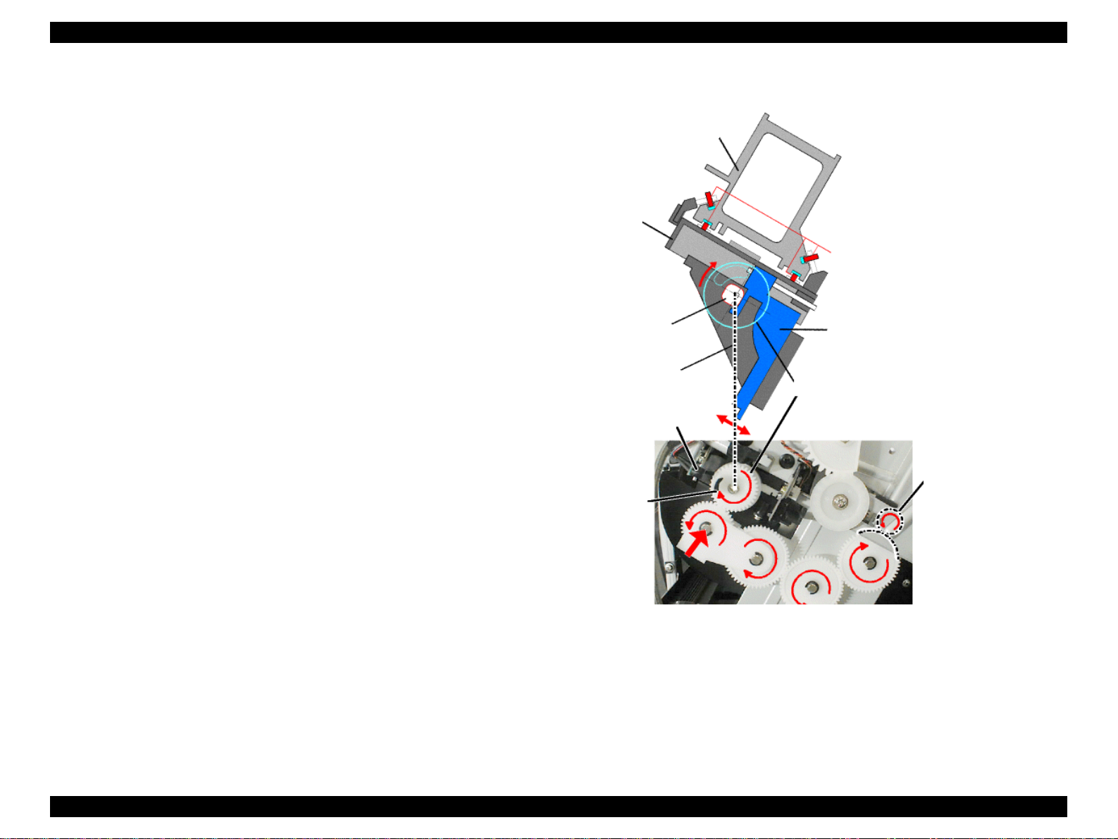
EPSON Stylus Pro 7500 Revision c
When the carriage is in the HP p osition ( = right end) , the pump motor and the g ear mounted
on the cam shaft engage, the motor’s rotation (reverse) drives the cam and the sub-carriage
is positioned at the proper gap position.
In order to maintain the distance between the print head nozzle surfaces and the paper, the
thicknesses of the paper used are classed into 3 levels, PG small (1.3 mm) / Medium (2.2
mm) / and Large (2.7 mm) when carrying out PG setting.
Carriage
NOTE: It is also possible to set the PG value manually. For details, see the item
“Platen Gap” in 1.6.1, “Printer Setting Menu.”
CR Guide Rail
The print heads consists of two heads, the dark type ink (B) head and the light type ink (C)
head.
Ink viscosity is influenced by temperature. In order to control the ink discharge rate and
discharge volume so that they are the same even if the temperature changes, each respective
print head has a built-in thermistor for detecting the head temperature.
NOTE: The B and C print heads used in this printer are the same model No. as
those used in the Stylus Pro 5000/9000.
Bearing
<Carriage Right Side
PG (Head SLID)
B/C Print Heads
PG_HP Sensor
PG_HP Flag
Sub-carriage (B and C
heads mounted)
Slide Gear
Pump Motor (CCW )
<view of right side
Figure 2-3. Carriage Mechanical Unit and PG Adjustment Unit
The sensors used in the platen gap adjustment unit are explained below.
View>
of printer>
o HD-SLID (Head Gap Home Position Detection) Sensor
This sensor detects the mechanical home position when the position of the subcarriage (head height from the paper surface) on the carriage undergoes change. A
reflective type photosensor is used and the position of the flag on the gear mounted
on the camshaft is detected. When the sub-carriage has dr opped down to its lowest
Operating Principles Print Mechanism Components 63
Page 64

EPSON Stylus Pro 7500 Revision c
position, the sensor is configured to go “O ff”, and during a sens ing oper a tio n, and
the point where the head changes from movi n g up to movi ng down and t he sens or
output switches from “OFF” to “ON” is recognized as the mechanical home
position.
o P_EDGE (Paper Width Detection) Sensor
This sensor is mounted on the left rear of the carriage. It detects the left and right
edges of the paper and carries out paper width recognition and skew judgment. A
reflective type photosensor is used and the paper edge (presence or absence of
paper) is judged with the sensor output in the form of an 8-bit A/D converted
value.
NOTE: It is possible to turn this sensor off in 1.6.1, “Printer Sett ing Menus.”
P_EDGE Sensor
Carriage
Left edge Right edge
HP Side
Paper
Figure 2-4. Carriage Unit Paper Width Detection Sensor
The Paper width detection sequence is shown in the figure at right.
Paper Left/Right
Edge Detection
CR in home position?
Move the CR to an
empty suction position.
Move the CR to a
position where there is
paper.
Carry out periodic
flushing (in the cap).
Is there paper?
Move the CR to the
no paper position.
No paper?
Measure the no
paper level.
Move the CR to the
position where there
is paper.
Set the maximum moving distance and
while detecting the paper level, move
the CR to the position where the "No
paper" level is detected at the paper's
Paper right edge
Set the maximum moving distance and
while detecting the paper level, move
the CR to the position where the "No
paper" level is detected at the paper's
Paper left edge detection.
right edge.
No paper?
detection.
left edge.
No paper?
Right Edge Left Edge
Solid Line: Paper
Broken Line: Printable Area
Error
Error Content:
Return
(Set the paper correctly.)
Figure 2-5. Paper Width Detection Sequence
Operating Principles Print Mechanism Components 64
Page 65

EPSON Stylus Pro 7500 Revision c
o
Cutter Solenoid
This solenoid is mounted on the left side of the carriage, and by activating the
cutter which performs cutting of roll paper while moving together with the
carriage, it causes the roll paper to be cut.
This function can be set On or Off using the Panel buttons.
NOTE: See 1.2, “Print Specifications.”
Carriage
Cutter
Roll Paper
Solenoid
Cutter
Figure 2-6. Carriage Unit Cutter Solenoid
Operating Principles Print Mechanism Components 65
Page 66

EPSON Stylus Pro 7500 Revision c
2.2.2 Paper Feed Assembly
This printer uses friction feed to carry out highly precise feeding of roll paper and cut
sheets, and comprises a unique paper feed mechanism.
Secondary Roller
Assembly
PF Motor
Grid Roller
R = Paper width flag
L = Paper Set Lever flag
Paper Set Lever
A DC servomotor is used for the PF motor and feedback control is carried out based on
pulses output by a rotary encoder senso r built in to the m otor, thu s maintainin g high p rinting
precision.
Driving of the grid roller is accomplished by the PF motor via the PF timing belt which
attaches to a reduction pulley that is connected to the grid roller.
Pressure and follower roller assembly
Secondary Roller Assembly
Grid Roller
Center Frame
CR Guide Rail
Speed-Reduction Gear
Platen
Subplaten
Paper
Paper Guide L1, L2
PF Motor
Figure 2-8. Paper Feed Mechanical Unit PF Rail Unit
Figure 2-7. Paper Feed Mechanism Unit 1/2
Two suction fans are mounted behind Paper Guide L2. The space in the column direction
The paper feed mechanism unit is configured from a grid roller (one piece construction),
and pressurizing and follower roller assemblies mounted on the back of the CR guide rail
opposite the front surface.
behind Paper Guide L2 is divided into 2 compartments, and one fan is mounted in each
compartment. By drawing air through multiple holes punched in Paper Guide L2 in the
back surface of the paper path and blowing it out through the rear of the printer housing,
suction is applied to the surfaces of Paper Guides L1 and L2 and the paper is stabilized
Operating Principles Print Mechanism Components 66
Page 67
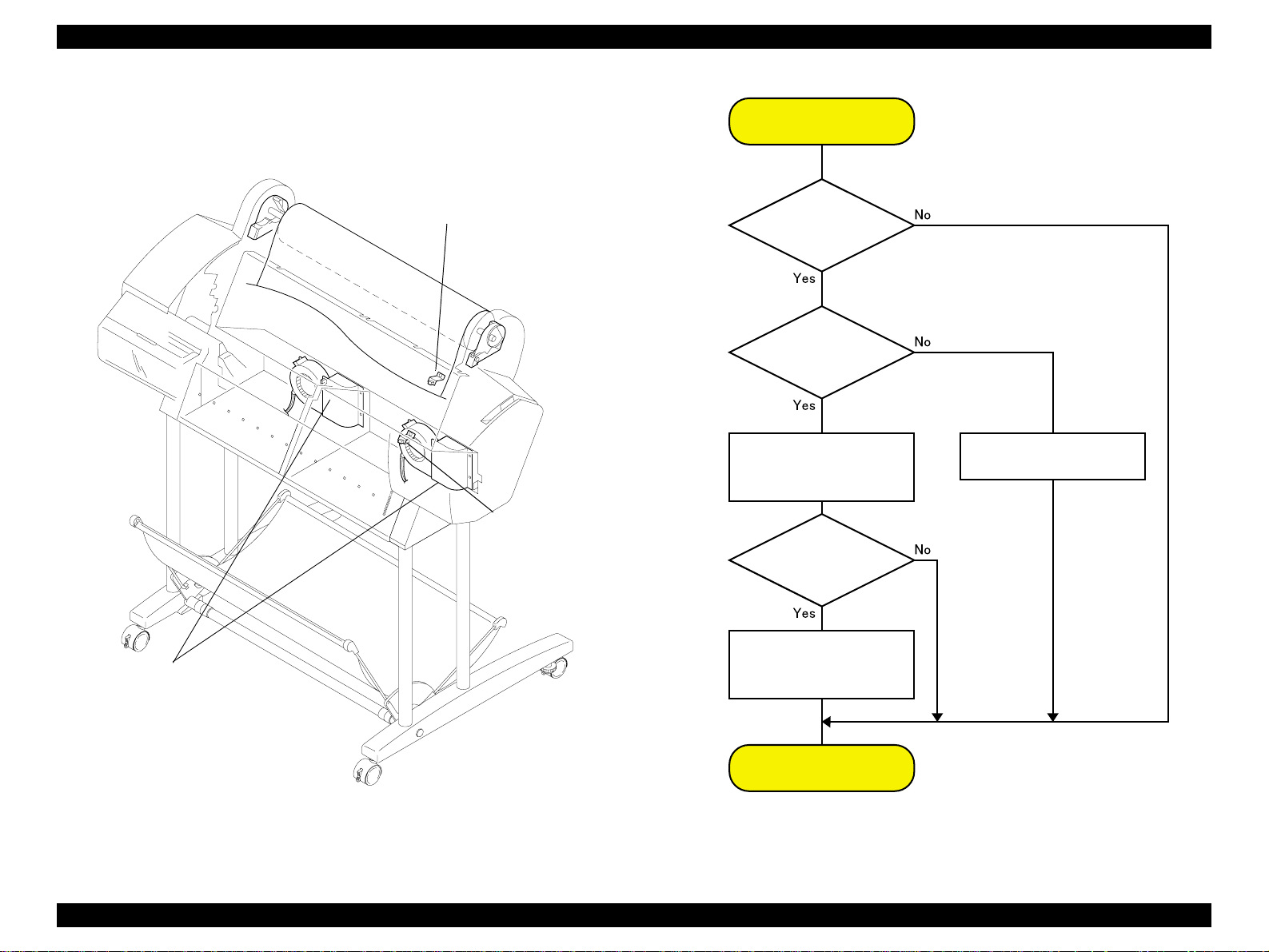
EPSON Stylus Pro 7500 Revision c
(prevented from flying up) as it passes through the printer. The suction fans undergo air
flow control (fan rotation duty control), which is carried out by firmware control based on
the printer’s operating state (when paper is set and during printing, etc.) and the type of
paper used.
Paper Suction
Fan Control
paper suction fans
P-Rear sensor
P-Front sensor
Paper Set
lever in released
(up) state?
Is the
P_REAR sensoron?
(Is paper present?)
Run the suction fans at
low speed and attract
the paper.
Is the
P_FRONT sensor on?
(Is paper present?)
Run the suction fans
at high speed and
attract the paper.
Stop the suction fans.
End
Figure 2-9. Paper Feed Mechanical Unit 2/2
Figure 2-10. Paper Suction Fan Control
The next page shows suction fan control during paper feed.
Operating Principles Print Mechanism Components 67
Page 68

EPSON Stylus Pro 7500 Revision c
The following sensors aid in the paper feeding process.
o P_FRONT sensor
This sensor is attached to the subplaten and is an optical (photo-reflective) sensor.
This sensor detects the front edge of the paper after paper has been loaded but
before it is set and ready to print.
o P_REAR sensor
This sensor is attached to the Upper Paper Guide and is an optical (photoreflective) sensor. This sensor detects the rear edge of the paper and detects the
front edge when the paper is first loaded in the paper path. The position of this
sensor is stored in EEPROM.
o P_THICK sensor
This optical sensor physically gauges whether the paper falls into the normal/thin
category or the thick category.
Table 2-2. Paper Thickness Detection
Paper Type Detected Thickness Sensor Si gnal
Thin Paper 0.6mm or less On 0.7V or more
Thick Paper 0 .7 mm or more Off 2.4V or more
*1:When the paper thickness is 0.6 ~ 0.7 mm, it is not definite which will be detected.
Output Sign al
Strength
o Release Sensor
A transmissive photosensor is used and it is mounted on the H top cover rear side
(right). It is constructed so that the sensor detection lever is linked to the paper
support lever’s operations. When the paper support lever is in the forward
position, it is in the set state (Fixed position).
Also, when the release sensor is in the “Release” state, the CR motor and PF
motor are stopped.
2.2.3 Cleaning Mechanism
The cleaning mechanism in this printer is compatible with the cleaning mechanism in the
Stylus Pro 5000/9000. The cleaning mechanism is located on the right side of the printer.
The waste ink from the cleaning mechanism is channeled to the waste ink pad in the lower
right side via 2 thin tubes and 1 pipe. (See the figure below.)
Maintenance assembly
Waste ink pads
Figure 2-11. Cleaning Mechanism
Flushing box
Pump motor
Pump rotat i on : CW
CR Lock
Head
cleaner
Pump assembly
Cap assembly
Figure 2-12. Cleaning Mechanism Components
Operating Principles Print Mechanism Components 68
Page 69

EPSON Stylus Pro 7500 Revision c
The cleaning mechanism components are installed above the subframe and some are fixed
on the main frame as shown below.
o Pump assembly (head cleaner)
When the head is in the capped position (valve closed), the pump motor creates a
vacuum that sucks ink from the nozzles. This is used for removing ink from the nozzles
and nozzle plate, initial ink charge, as well as cleaning. The waste ink flows through
two small tubes to the waste ink pads.
o Head cleaner
The head cleaner has felt on one side and rubber on the other, and is used to wipe or
rub off ink and foreign materials from the nozzle surface.
o Pump motor
Clockwise rotation = pump assembly drive for cleaning and so on
Counter clockwise ro tation = pla ten ga p adjustm e nt
o Cap assembly (one pad for each printhead)
When not printing, the printheads (should) rest on the cap assembly to make sure the
nozzles don’t clog. Also, the printhead s are in the capped p osition during ink charging ,
cleaning, and so on.
o Flushing box
Flushing (dummy printin g) is perform e d over the flushin g box , and the flushe d ink
flows through the large diameter tube to the waste ink pads.
o CR Lock Mechanism
If the carriage moves from the printable area to beyond the capping (CR_HOME)
position to the right, the carriage moving prevention lock is engaged. The CR lock
mechanism uses the cutter solenoid in common. When the cutter solenoid goes ON in
the capping position, the CR lock is released.
NOTE: The “Ink System Terms” used in the above text are explained in the
following table.
Table 2-3. Explanation of Operation
Operation Explanation
Carriage
(CR) Lock
Ink Initial
Filling
Flushing
Empty
Suction
Operation
Wiping
Operation
Rubbing
Operation
Capping
• This is the carriage stop position when the power is Off.
• The time when the carriag e is in th e sta ndby p osit ion (h om e p osit ion ) with t he
power On and with no paper loaded and no print data to print.
• This is the operation where the head is filled with ink for the first time.
When the first ink cartridge is inserted (after all 6 colors have been inserted), the
ink initial filling operation is performed automatically.
• The initial filling flag is set when the printer is shipped from the factory, then
after this operation, the initial filling flag is reset. The initial filling flag is also
set after the “Inter-User Transport Mode” is run.
• In order to prevent the viscosity of the ink inside the head nozzles from
increasing, the ink inside the flushing box is flushed out.
• Flushing is done when paper is set, when printing from the standby state,
during continuo us printing, during paper Eject, during paper cutting, etc.
• After ink is sucked up, the remaining ink inside the cap is sucked up and the
ink adhering to the head no zzle surface is removed.
• Through flushing, etc., the ink that has accumulated in the cap is sucked up
and discharged.
• After ink is sucked up, any dust, etc. adhering to the head nozzle surface is
removed and tight fitting of the cap is assured.
• Any ink or dust, etc. that has adhered to the head nozzle surfa ce after ink
suction is removed, and the no rmal ink spray state is recovered.
The head nozzle surface is wet with a tiny amount of ink, then the head nozzle
surface is cleaned off, with any tightly adhering dirt, etc. being removed, thus
assuring that the cap will fit tightly.
In order to prevent the ink viscosity from increasing while it is being kept, a
rubber cap is placed over the prin t head nozzles when entering a shutdown
operation.
Operating Principles Print Mechanism Components 69
Page 70
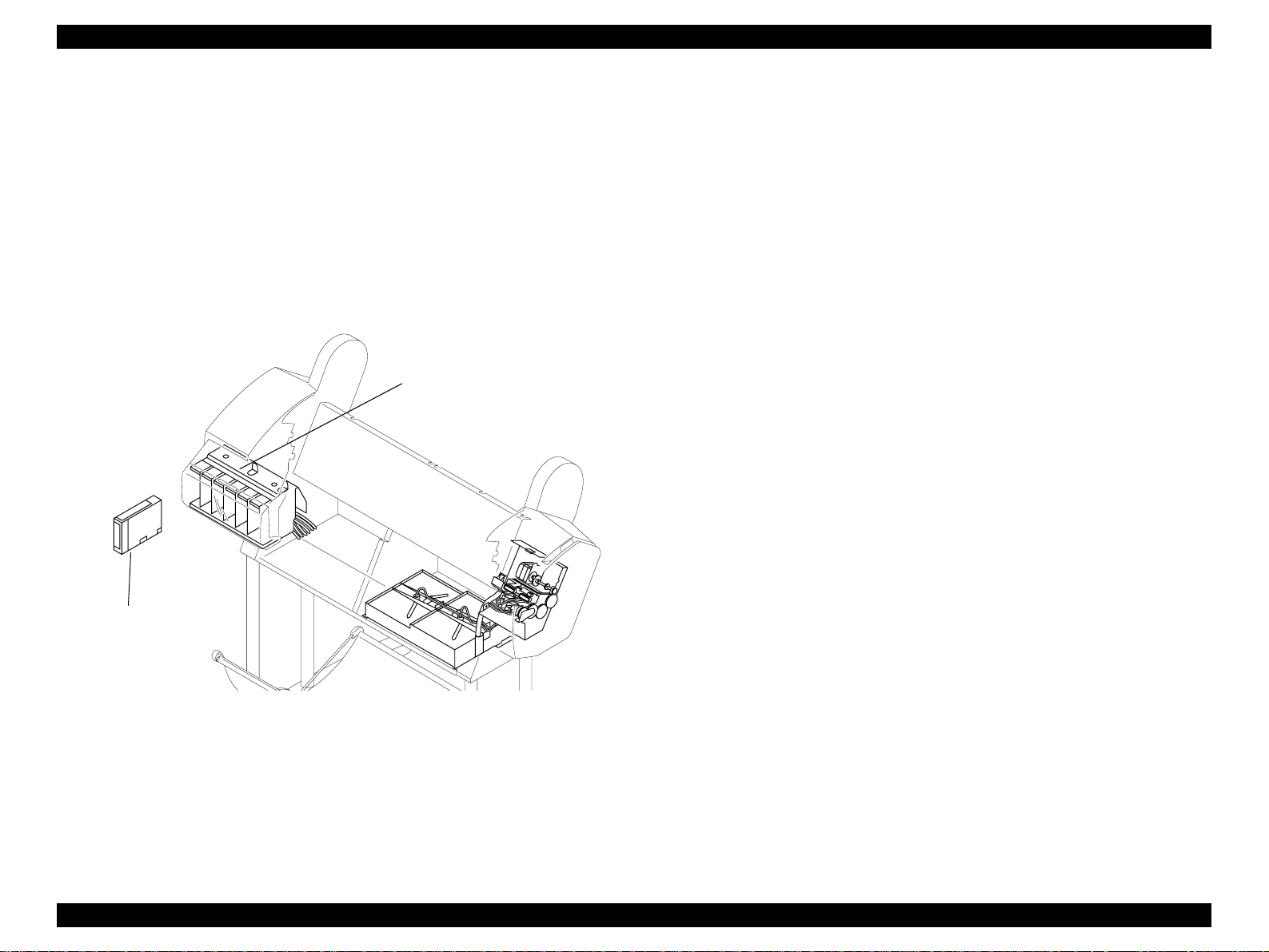
EPSON Stylus Pro 7500 Revision c
2.2.4 Ink Supply Mechanism
In this printer, there is an ink holder on the left side (I/H) where 6 ink cartridges, one of each
color, (from the left), K, C, M, Lc, Lm and Y, are installed. A projection and unique
markings are placed on each color ink cartridge case to prevent wrong insertion so that the
wrong color cartridge is not inserted and so the cartridge is inserted in the right direction.
NOTE: This printer does not use the ink valves which are used in the Stylus Pro
9000 and Stylus Pro 9500. Therefor e, i f you are tra ns por t ing t he pr int er,
in order to prevent ink from leaking from the ink channel, all the ink
should be discharged by running the Inter-User Transport Mode, then
carrying out parking and transport.
Ink cartridge holder
o Ink Cartridge (I/C) Detection Sensor
This sensor uses a microswitch to detect when the ink cartridge is installed.
I/C Installed state (Present):Switch closed
I/C Not Installed state (None): Switch open
o Ink End Detection Sensor
This sensor uses a mechanical switch to detect the amount of ink remaining in
each ink cartridge. Through a detection flag which changes according to the
amount of ink remaining in the ink pack inside the ink cartridge, the switch is
turned ON or OFF, and thus carries out detection.
Ink cartridge
Figure 2-13. Ink Supply Mechanism
The ink flow is as shown below.
Each color’s ink cartridge -> Each color’s I/H (Ink Holder) -> Each color’s ink tube -> Each
color’s head dumper (carriage) -> B and C Print Heads
The following sensors are mounted in each color’s I/H (Ink Holder).
Operating Principles Print Mechanism Components 70
Page 71

EPSON Stylus Pro 7500 Revision c
Amount of ink remaining low (ne ar end) : Switch op en
Amount of ink remaining sufficient (Normal): Switch closed
Ink Cartridge
Ink Low Sensor
Ink Cartridge Sensor
2.2.5 Other
COVER SENSOR
In order to detect whether the front cover on the lower front of this printer is open or closed,
a cover sensor is mounted on the printer on the left side where the front cover opens and
closes.
This sensor carries out control of operating and stopping of the CR motor and PF motor
drive circuits via the C299MAIN board’s logic circuit after detecting the cover’s status.
This control is the same when the paper support level is in the release state.
Cover Sensor
Front Cover Flag
Panel Unit
Front Cover
Figure 2-14. Ink Supply Mechanis m Sensors (from right side)
Figure 2-15. Cover Sensor Panel Unit
Operating Principles Print Mechanism Components 71
Page 72
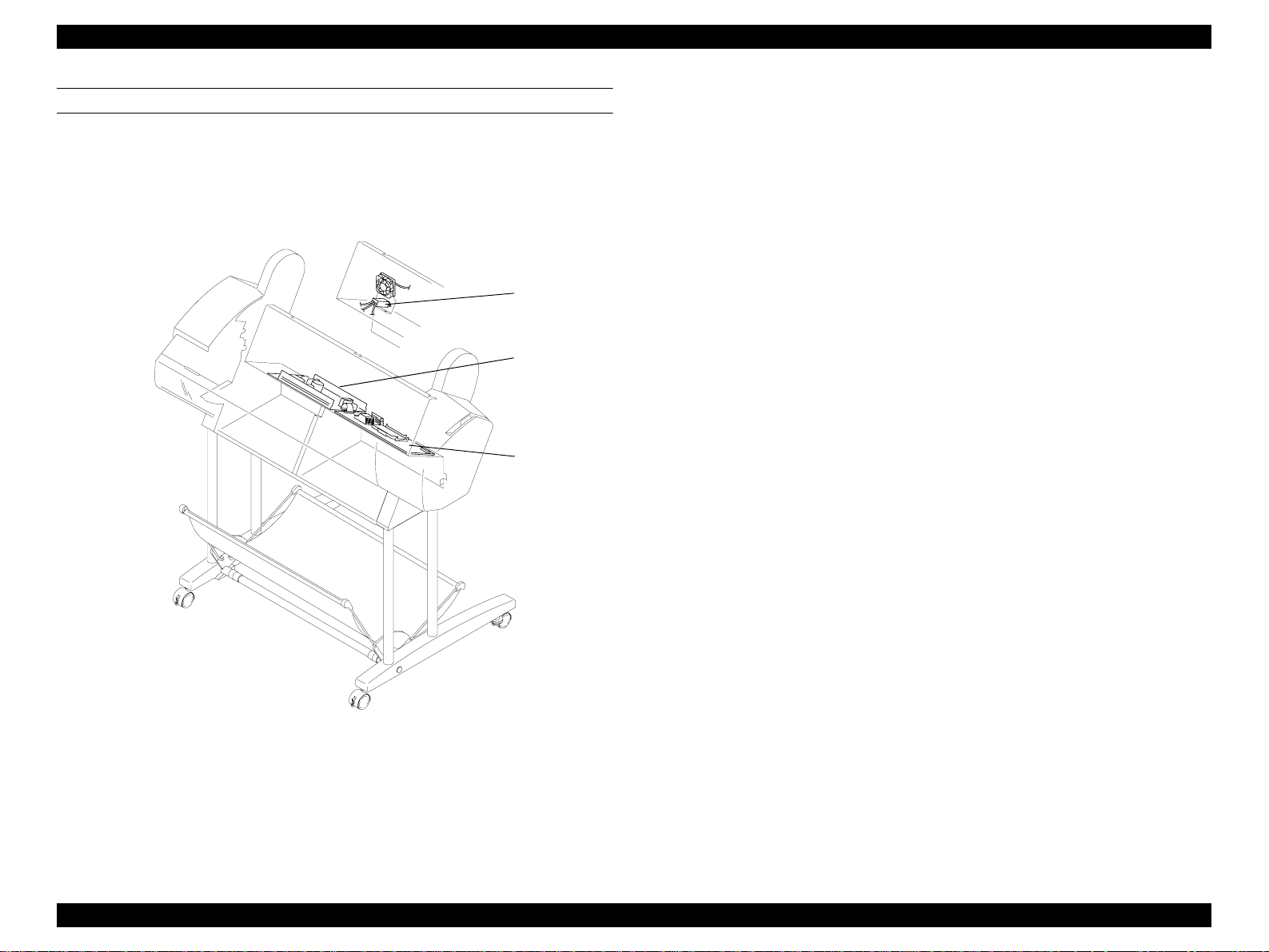
EPSON Stylus Pro 7500 Revision c
CIRCUIT BOARD PLACEMENT
The panel unit is located i the right front of the printer and the AC inlet, power supply
circuit board and the C299MAIN circuit board are mounted in the compartment on the
printer’s rear side.
AC Inlet
Power Supply
Circuit Board
C299 MAIN
Circuit Board
Figure 2-16. Circuit Board Layout
Operating Principles Print Mechanism Components 72
Page 73

EPSON Stylus Pro 7500 Revision c
2.3 Control Circuit (C299MAIN Board) Outline
Here, we give a brief expla nation of the ope ration of the C299MA IN bo ard wh ich perf orms
printer mechanism control and driving in this printer.
A block diagram of this main control circuit is shown in the figure at right. The major IC’s
on the C299MAIN board are also explained in Table 2-4.
[Note] For details of each circuit, see the “C299MAIN Board Circuit Diagrams” at the
back of this manual.
Figure 2-17. C299MAIN Board-Circuit Block Diagram
Operating Principles Control Circuit (C299MAIN Board) Outline 73
Page 74

EPSON Stylus Pro 7500 Revision c
Table 2-4. Control Circuit Operation
Name/Code Location Function
CPU (C90A14CA)
SH7043
ASIC (E06A4610A)
ASIC (E05B61AA)
ASIC (TE7751)
ASIC (uPD65802)
IC8
IC9
IC13
IC20
IC32
32 bit RISC-CPU
• Clock speed = 32.768MHz
• 128KB PROM (IPL) internal
I/O port expansion
1) Regulates print data
• Command handling
• Rasteri zer (image data ha ndling)
• Head drive regul a tion (DAC control)
• Print timing regulation
2) Memory (DRAM/SRAM)
3) I/F Circuit Control
• Parallel interface (IEEE1284)
• USB interface
•Type-B
Motor regulation
• Pump Motor (pump/PG)
• Cutter solenoid
• Fan (Paper suction) x2
Motor regulation (PWM regulation)
• CR Motor
• PF Motor
Table 2-4. Control Circuit Operation (continued)
Name/Code Location Function
Serial EEPROM
EEPROM
M51953BFP
Driver IC (L6203)
Driver IC (LB1845)
Driver IC
(MMDF205ZR2)
PQ3RD13
IC61
IC80
IC33, IC35
IC30
IC41, IC43
IC15
Head drive D/A factory adjustm ent
parameters
USB-ID factory settings
Reset IC
CR/PF Motor Drivers
Pump Motor Driver
Suction fan x2 and cutter solenoid driver
+3.3V regulator
DAC (M65530FP)
Flash Memory
(MBM29F400TC)
DRAM (EDO)
SRAM (LC3564SM-
10)
IC37
IC1, IC2
IC73~76
IC81, IC82
IC39
3 channel 10 bit DA converter
• head-drive voltage co ntr ol
Flash Memory (1Mbyte)
• Save firmware
• Register D/A, user defined, and factory
default setting parameters
EDO RAM
• 10Mbyte (onboard)
64Kbit SRAM
• External data ring buffe r type
Operating Principles Control Circuit (C299MAIN Board) Outline 74
Page 75
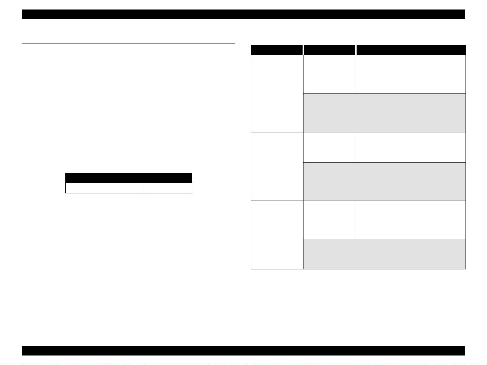
EPSON Stylus Pro 7500 Revision c
2.4 Power Supply Board Summary
Depending on the printer model, either 100V AC or 220V AC is supplied to the printer
when the printer is plugged into an liveoutlet.
The power switch consists of a secondary power switch system. A secondary power switch
system is a system where the power supply board operates with a minuscule power level as
long as the power cable is connected, even when the power switch is turned off.
NOTE: The power supply board is configured so that it does not stop
immediately even after the power switch is turned Off, but after the ink
system’s end sequence has been perfor med, the power goes Off.
Therefore, the printer should not be operated by turning a power supply
tap switch On and Off.
The power supply board is equipped with an overcurrent protection fuse for protecting it
against overcurrent. The fuse rating is shown in the following table.
Table 2-5. Fuse Rating
Input Voltage Range [V AC] Fuse Rating
100V AC ± 10% 125V AC/6.3A
The C299MAIN board has three control signals, described in detail in the table below.
Table 2-6. PS Board Signal Summary
Signal Name Condition Function
On and Off is controlled by the C299MAIN
board.
During operation
+28V/+42V
REM_ON
(MAIN ->PS)
Printer off
During operation
(= H)
AC_OFF
(MAIN<-PS)
Printer off
(= L)
Turning on
POWER_SW
(Panel/MAIN -> PS)
Turning off
• If this terminal is shorted, the drive system
power supply, 28 V DC and 42 V DC, becomes
active.
• If this terminal is cleared (= L), the drive
system power supply, 28 V DC and 42 V DC,
becomes 0 V DC.
• The 5 V DC powe r supply is not co ntroll ed by
this terminal.
The power switch goes On, the power supply
board unit starts and each output becomes
active. Afterward, the “H” signal is sent to the
C299MAIN board.
The power switch goes Off, and the each output
of the power supply board unit becomes
inactive, or if the input voltage drops belo w the
rated voltage value, the “L” signal is sent to the
C299MAIN board.
This is connected to the panel unit’s power
switch.
• When the switch is in the On state, this
terminal is shorted. the power supply board
changes to the operating state.
• When the switch is in the Off state, this
terminal is cleared. After waiting in the
operating state for 10 plus seconds and up to
several minutes, the power supply unit goes off.
Operating Principles Power Supply Board Summary 75
Page 76

TROUBLESHOOTING
CHAPTER
Page 77
EPSON Stylus Pro 7500 Revision c
3.1 Outline
This section explains procedures for rapid and efficient troubleshooting if trouble occurs in
the printer.
3.1.1 Introduction
First of all, when performing troubleshooting, the following basic parts should be checked.
1. Look in the printer for any foreign matter and make sure there is nothing there to
hinder normal operation.
2. Carry out printing by setting the printer in the “Pause” state, then press the [SelecTyp e]
button 2 times. Next using the [Paper Feed] switch in the “TEST PRINT MENU,”
select “ATATUS CHECK”, then press the [Enter] switch and print.
From the status sheet, you can check if the cause of the trouble is that the printer (either
the printer unit itself or some major unit) is at the end of its service life, and check the
user inherent panel settings, etc.
3. There should be no market soiling of the outside or the inside of the printer. If it is
extremely soiled, carry out cleaning.
4. Each of the units and parts in the printer should not be missing or damaged, and should
have the normal shape and configuration.
5. Each of the harnesses should be undamaged, and s hould be correctly connected to the
relevant connector (perpe nd icula rly and in the correct dir ectio n).
9. As necessary, initialize the NVRAM on the C299MAIN board (return the individual
customer settings and panel settings to the factory settings).
Carry out initialization by executing “INIT. NVRAM” from the “CLEAR
COUNTERS MENU” in “Maintenance Mode 2.”
CHECK
PO IN T
CAUTIO N
When disassembling the printer, turn the printer’s power switch Off,
then after making sure that the panel display is off, pull out the power
cable from the outlet and disconnect the interface cable.
1. Only the specified printer tools should be used so as to maintain the
printer’s quality.
2. Only the specified lubricants and adhesives should be used.
3. The specified adjustments should definitely be carried out.
6. Each cam and gear in the printer mechanism should have no uneven wear or be overly
worn, and the combinations should be correct.
7. Each type of rubber roller in the printer mechanism s hould be cleaned and it should be
ascertained whether the cause of the trouble is because of dirt or due to some other
cause.
8. Each type of rubber roller in the printer mechanism should not be unevenly worn or
excessively worn, and their combinations should be correct.
Troubleshooting Outline 77
Page 78

EPSON Stylus Pro 7500 Revision c
3.1.2 Troubleshooting Practice
Here, the troubleshooting check points and check contents in the case that trouble occurs in
this printer are explained. Troubleshooting is divided into the following items.
o Troubleshooting based on an Error Display
3.2 Troubleshooting Based on Error Display (Object: User, Service Man.)
3.3 Errors handled by th e service man (Object: Service Man)
o Troubleshooting Based on Printing Results
3.4 Troubleshooting Based on Printing Results (Object: Service Man)
Hereafter the check points and check contents in the above troubleshooting items are
explained.
Troubleshooting Outline 78
Page 79
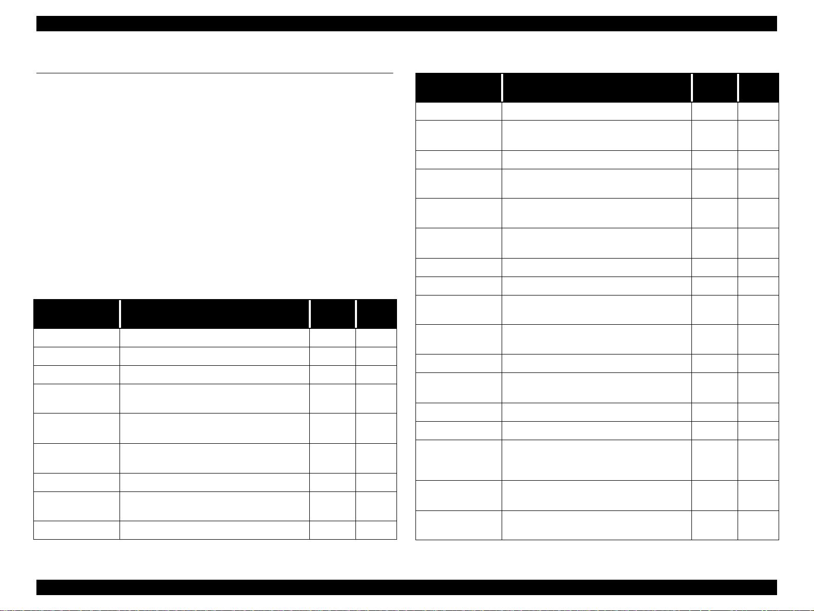
EPSON Stylus Pro 7500 Revision c
3.2 Troubleshooting Based on Error Display
This printer executes self-diagnosis based on the status detected by each sensor, detects
abnormal states by the results of the self-diagnosis and displays the error status by means of
error messages.
If any error display occurs, check the relevant error items from th e panel d isplay list sho w n
below and take the appropriate action. (refer to the check points and the treatment content
and take measures to correct the trouble.)
For methods of treating errors that require a service man which are not covered in the
“User’s Manual” which was supplied with the printer, see the item “Errors That Require a
Service Technician” in 3.3. *1
*1: Errors that Require a Service Man
The necessary error occurrence states for treatment accompanying checks
or replacement of the relevant parts by a service man are shown.
Table 3-1. LCD Panel Error Messages
LCD message Status Type
INK OUT Ink End, Wrong Ink Cartridge Error
INK DRY nn MIN Ink drying Status
INK LOW Ink low Warning
INK CHARGING
nnn
LOAD INK
CARTRIDGE
PRESS PAUSE
BUTTON
READY Printer is ready Status
ANABLE TO
PRINT
PRINTING Printing the current print job. Status
Initial Ink Charge Status
Performing ink cartridge replacement Status
Waiting for the paper-initialization trigger Status
Cannot perform test print. Error
Refer to
page
81
84
86
Table 3-1. LCD Panel Error Messages
LCD message Status Type
OPTION I/F ERROR Type-B interface error Error
NO INK
CARTRIDGE
COVER OPEN The cover is open Error
TURN PWR OFF
AND ON
SERVICE REQ.
nnnnnnnn
WAIT
POWER OFF Performing power-off sequence Status
PAUSE Printer paused Status
MAINTENANCE
REQ. nnnn
TRANSPORT PREP
nn%
PAPER NOT CUT Paper cut error E rror
PAPER NOT
STRAIGHT
PAPER JAM Paper jam occurred Error
PAPER OUT No paper loaded or roll paper end Error
SECURE PAPER
LEVER
LOAD PAPER
RELOAD PAPER
One or more ink cartridges not installed Error
The printer needs to re-initialize. Status
Fatal error occurred Error
Initializing printer, initializing paper, charging
ink, resting timer IC, or clearing NVRAM
Maintenance required (waste ink pad
replacement)
Draining transport fluid (100% = end) Status
Paper fed at a slant Error
The Paper Set Lever was moved to the Released
position during printing and must be returned to
the Set position.
Paper is loaded but the Lever is not in the Set
position. Move to the Set position.
Paper recognition error or paper feed/exit error
(cut sheets only)
Status
Warning
Error
Error
Error
Refer to
page
85
85
83
86
81
83
83
83
82
84
84
Troubleshooting Troubleshooting Based on Error Display 79
Page 80

EPSON Stylus Pro 7500 Revision c
Table 3-1. LCD Panel Error Messages
LCD message Status Type
REMOVE PAPER
RESET Re-initializin g the printe r Status
LOAD xx PAPER Roll paper/cut sheet size error Error
Paper is too thic k for cleaning and must be
removed for cleaning.
Error
*1: The PG setting panel display shows a “H” in the 20th colu mn in t he LCD only when the
PG setting is major.
*2: The progress of treatment is shown by %. (100% signifies completion.)
*3: The display priority order in the case of multiple occurrences of errors is shown below.
Refer to
page
82
Table 3-2. Printer Status Display Priority Order List
Table 3-3.
Priority O rder
High Fatal Error / Restart Request
↑ Resetting Timer IC / Clearing NVRAM / Resetting
Executing power off sequence / Inter-User Transport mode
Displayed Function
Priority O rder
Paper skew error
Paper recognition error
Roll paper end
Paper Eject error
Initialization operatio n in progress
Cleaning impossible error
Executing ink sequence
Waiting for paper initialization start trigger
Pausing
Paper initialization in progress
Ink drying
Ink low / Maintenance request
↓ Processing data / Pause
Low No paper
Table 3-3.
Displayed Function
Replacing ink cartridges
Cover open
Paper support lever released during operation
Paper support lever currently released
Type B Interface error
No ink cartridge
Ink end
Roll paper / Cut sheet settings different
Paper jam
Paper cutting error
Troubleshooting Troubleshooting Based on Error Display 80
Page 81
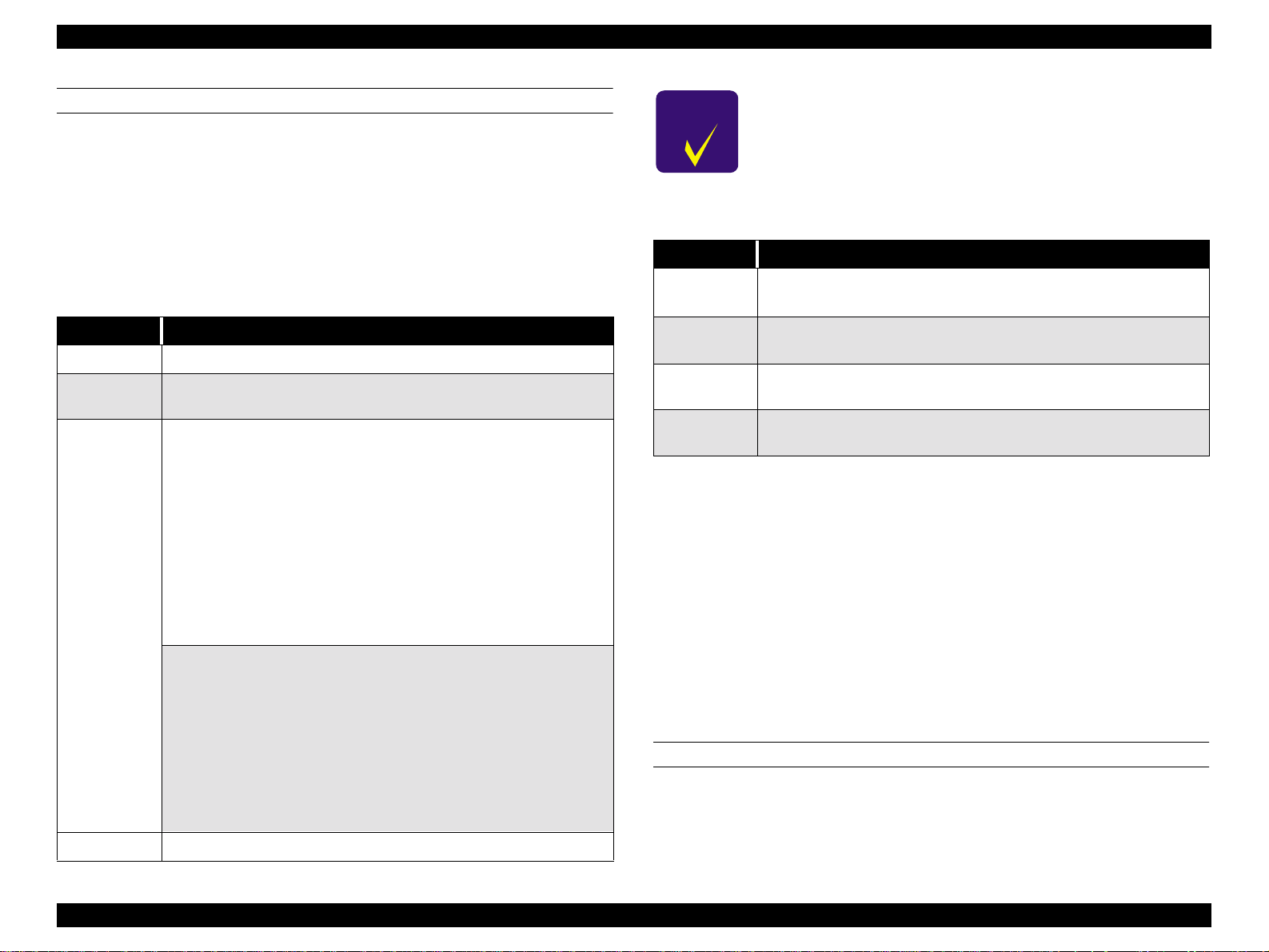
EPSON Stylus Pro 7500 Revision c
WARNINGS
Warning messages appear on the LCD display to warn users that a problem may occur. The
printer can still print and there is no effect on print quality; h owever the m essages do not g o
away until the possible problem is taken care of or the printer enters the correspondi ng error
condition. For example, the Waste Ink Pads Near Full message will remain until the pads
are replaced and the counter is reset or until the pads become full and the printer enters an
error state.
Table 3-4. Ink Low
Item Description
LCD message INK LOW
LED indicator
status
Details
Recovery Replace the old ink cartri dge with a new one.
The LED indicator for the ink cartridge that is low flashes.
If the standard 100 cc ink cartridge is installed:
The printer detected that the soft c o un ter for o ne of th e ink cartridges was at
Near-End. When the soft counter’s Near-End si gnal is generated, it means
that the cumulative number of dots is counted by software, and that the
remaining amount of ink has been calculated to be less than 10%.
After Ink Low is displayed, it means, as a cri te r io n, that the area of an A1
sheet can be printed with 100% duty, but the ink cartridge should be
replaced as quickly as possible.
When replacing an ink cartridge, a new cartridge which is full of ink should
be installed. (A partially filled ink cartridge that has been removed should
not be installed a second time.) If this is not strictly observed, the correct
operation of the r e maining ink indica tor cannot be guarante ed.
If the large capacity 200 cc ink cartridges are in st alled:
The printer detected the Near-End signal for one of the i nk cartridges. The
Near-End state is detected by the pos iti on of the sensor plate inside the
cartridge, and judgment made. After Ink L ow is displayed, as a criterion, it
means, as a criterion, t hat the area of an A1 sheet can be printed with 100%
duty, but the ink cartridge should be replaced as soon as possible.
When replacing ink cartridges, a new cartridge which is full of ink should be
installed. (A partially filled ink cartridge that has been removed should not
be installed a seco nd time.) If this is not strictly observed, the correct
operation of the r e maining ink indica tor cannot be guarante ed.
CHECK
PO IN T
If it is necessary to replace the ink cartridges before Ink Low or Ink
End is detected, and when replacing all the ink cartridges with new
ones, the counters should definitely be reset.
Reset the counters by “Maintenance Mode 2” -> “Counter
Initialization Menu” -> “Ink Initialization.”
Table 3-5. MAINTENANCE REQ. nnnn
Item Description
LCD message
LED indicator
status
Details
Recovery
MAINTENANCE REQ. nnnn
nnnn = the replacement part code *1
No change.
Maintenance re quired. The corresponding part described by the nnnn has
almost reached the end of its effective life. Service is required.
Replace the old part(s) with new ones (Maintenance Kit 1054038) and reset
the corresponding counters (Waste Ink and Cleaning).
*1: 0100
[Parts Subject to Replacement]
- Waste ink pad
- Flushing box
- Pump assembly
- Cap assembly
- Cleaner, head
* A periodic replacement parts kit containing these parts as a set, “Maintenance
Kit Stylus Pro 7500 (No. 1058463)” is available.
[Counters to be Cleared]
Clear the counters by “Maintenance Mode 2” -> “Counter Initialization Menu.”
- Waste Ink Initialization
- Cleaning Initialization
ERRORS
Error messages appear on the LCD to notify the user that the printer cannot print properly
under the current conditions. When an error message appears, printing stops and data
transfer from the host PC stops. (The parallel interface signal = /ERROR -> “LOW” and
BUSY -> “HIGH” and data cannot be entered.)
Troubleshooting Troubleshooting Based on Error Display 81
Page 82
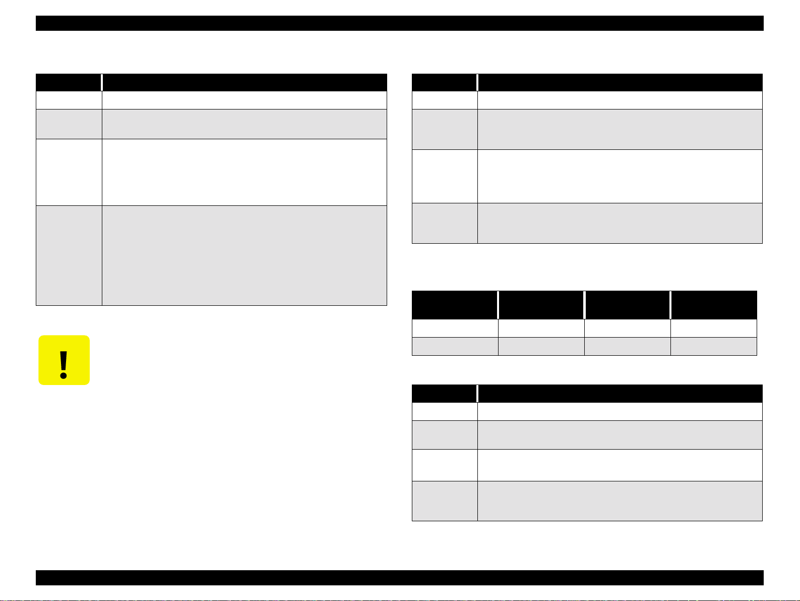
EPSON Stylus Pro 7500 Revision c
Table 3-6. PAPER OUT
Item Description
LCD message PAPER OUT
LED indicator
status
Details
Recovery
CAUTIO N
Paper Check indicator is on
No paper loaded or the end of the roll paper.
When printing on roll paper, if the Paper End sensor detects the end of the
roll paper, paper feeding stops and the paper is held in place.
When printing on cut sheets, if the Paper End sensor detects the end of the
paper, printing as well as feeding stop and the paper is held in place.
Load paper.
For cut sheets, remove the printed sheet and load a new one. After loading
the new sheet, the error is cleared. If data from the previous print job
remains, the data is printed on the new sheet acco rdin g to the origi na l pape rsize data.
If this error occurs even if paper is properly loaded, check the P-REAR
sensor for obstruction or dust. Also make sure ther e is no foreign material
blocking the hole in the Paper Guid e U where the P-Rear senso r is located.
If you are cleaning the sensor, water or organic solvents should not be
used.
Table 3-7. LOAD xxx PAPER
Item Description
LCD message LOAD xxx PAPER
LED indicator
status
Details
Recovery
Paper check indicator is on and the currently selected paper path indicator
flashes. The paper path information is supplied by the PP remote
command.*1
Roll paper and cut sheet size settings differ.
The PP remote command determines the paper path, and when this setting
and the paper setting mad e via the c ontrol pa nel differ, this (paper m ismatch)
error occurs.
Load the correct paper size, or change the setting in the control panel/driver
to match the size of the paper loaded in the printer. When this error clears,
printing begins.
*1: See the table below.
Table 3-8. Paper Path Command and LED Indicators
PP Command
Roll Paper
Cut Sheets
Roll
Auto Cut
Flashing Flashing On
On On Flashing
Roll
No Cut
Sheet
Table 3-9. LOAD PAPER
Item Description
LCD message LOAD PAPER
LED indicator
status
Details
Recovery
The Paper Check indicator in on.
The Paper Set Lever is in the release position.
While loading paper, the Pap er Set Leve r was pu shed to th e releas e posit ion .
Pull the Lever forward to the paper set position to clear the error. If the error
doesn’t clear, check the Paper-Set-lever position sensor for dust or foreign
material. Also make sure t he se n sor is p rop e rly c onnec te d to th e Main b o ard.
Troubleshooting Troubleshooting Based on Error Display 82
Page 83

EPSON Stylus Pro 7500 Revision c
Table 3-10. PAPER JAM
Item Description
LCD message PAPER JAM
LED indicator
status
Details
Recovery
Paper Check sensor flashes
There is a paper jam.
During a printing, feeding, or cutting operation the paper jammed on a
printer part. A paper jam is detected when one of t he paper-edge sensors is
on and the CR motor has an out-of-step error or an overcurrent error is
detected.
Remove the paper from the printer, turn the printer off and back on, and try
to print again. If the er ror recu rs, m ake su re no thing b loc k s th e c arriage pa th
and there are no foreign objects inside the printer.
Table 3-11. COVER OPEN
Item Description
LCD message COVER OPEN
LED indicator
status
Details
Recovery
N/A
The front cover is op e n.When the cover is open the CR cannot move and no
printer operations such as cleaning can be performed. If the cover is left
open for a long period of time, the printhea ds may be affected adversely.
Close the front cover. The p rinter automatically returns to th e pre-error state;
i.e. “Ready” or “Paused”.
If the cover is opened during printing, printout quality may suffer. If you
have to open the cover for some reason while the printer is printing, first
press the Pause button to decrease the chance of adversely affecting printout
quality.
If this error occurs even though both sides of th e cover are securely closed,
check the cover-open sensor (interlock switch) on the left side for proper
operation and position.
Table 3-12. PAPER NOT CUT
Item Description
LCD message PAPER NOT CUT
LED indicator
status
Details
Recovery
Paper Check indicator flashes.
Paper cut error occurred.
The page was not cut entirely or the page was cut unevenly and part of it still
covers the P-FRONT sensor.
Open the front cover and remove any cut paper that has not fallen. If
necessary, cut the paper above the P-FRONT sensor with scissors. The LCD
will display the “RELOAD PAPER” message. Move the Paper Set Lever to
the release position and after making sure the leading edge is even, properly
reload the paper. If the error is due to a worn cutter blade, replace the blade.
Make sure the cutter and cutter solenoid are installed and working properly.
Also make sure the cutter positioning adjustment is being carried out
appropriately. See “5.2.4 .7 Cutter Positioning Adjustment”.
Table 3-13. PAPER NOT STRAIGHT
Item Description
LCD message PAPER NOT STRAIGHT
LED indicator
status
Details
Recovery
Paper Check indicator flashes.
Paper skew error occurred.
The lateral (horizontal) positi on of the le adin g e dge and re a r edge are off by
over 3mm.
When this error occurs, there is the possibility that ink has been fired onto
the platen; make sure the platen is clean. Also, you may need to reprint your
print job if the degree of skew is too much.
Set the paper correctly to clear this error.
Follow the directions i n the user’s guide carefully. If the roll paper is curve d
or bent near the edge, line up the leadi ng edge on both sid es. If reloadin g the
paper correctly does not clear the error, turn the printer off and back on.
Troubleshooting Troubleshooting Based on Error Display 83
Page 84

EPSON Stylus Pro 7500 Revision c
Table 3-14. RELOAD PAPER
Item Description
LCD message RELOAD PAPER
LED indicator
status
Details
Recovery
Paper Check indicator flashes.
There was a paper recognition error or cut sheet feeding error, which can
happen under the fol lowing conditions:
1) The user loaded the leading edg e of the pa p er too far into th e prin ter. Th e
printer can only reverse feed the paper a set distance, and if the paper is
loaded too far, it will not reverse feed far enough.
2) The printer detected that the paper was loaded outside of the printable
area/carriage path.
3) After printing, the printer detected that the paper is outside of the cutting
area/carriage path.
4) The printer detected that the cut sheet loaded in the printer is too long/
unsupported an d could not be fully ejected. This may occur if roll paper is
loaded but the control panel is set to cut sheets.
5) This error may occur after a Paper Not Cut error.
1-3 above) Correctly set the paper as described in the user’s guide. If the
front edge is not clean and straight, cut it evenly.
4-5 above) For roll paper cut off the section of the paper that has been
ejected and properly reload the paper. For cut sheets eject the remaining
paper and select Shee ts on the control panel or load supported pa per
depending on the cause of the error.
If after correctly reloading paper the same error occurs, check the operation
and connection of the P-EDGE sensor located on the carriage.
Table 3-15. SECURE PAPER LEVER
Item Description
LCD message SECURE PAPER LEVER
LED indicator
status
Details
Recovery
N/A
The Paper Set Lever was moved to the release positio n during operation.
Similar to leaving the front cover open for long periods of time, leaving the
Paper Set Lever in the release position (during operation) can have an
adverse affect on the printheads.
Return the Paper Set Lever to the set (forward) position.
The printer automatically returns to the pre - error state; i.e. “Ready” or
“Paused”.
Moving the Paper Set Lever during printing may cause a decline in printout
quality and is not supported by EPSON.
If after returning the Lever to the set position this error do es not clear, check
the operation and connection of the Paper Set Lever sensor.
Table 3-16. LOAD INK CARTRIDGE
Item Description
LCD message LOAD INK CARTRIDGE
LED indicator
status
Details Only occurs dur i ng ink ca rt ridge replacement.
N/A
The Ink End indicators only function when the ink is lo w/empty, whe n there
is no ink cartridge, or when an ink cartridge is loaded in the inco rrect sl ot.
Finish replacing the ink cartridge(s) and close the ink cartridge holder
Recovery
door.The printer automaticall y ret urns to the pre-error state; i.e. “Ready” or
“Paused”.
Troubleshooting Troubleshooting Based on Error Display 84
Page 85

EPSON Stylus Pro 7500 Revision c
Table 3-17. INK OUT
Item Description
LCD message INK OUT
LED indicator
status
Details
Recovery
CAUTIO N
The Ink End indicator f or the in corre ct slot (if an ink cartridge is installed in
the wrong slot) or empty ink cartridge is on.
The ink-end error appears after the ink-end sensor detects the near-end
condition and then a predetermined amount of ink is ejected. Also, if an ink
cartridge that is already in the near-end condition is loaded, the printer will
automatically produce this error.
In cases w h ere an in k ca rtr i dge is load e d i n t he w ro ng s lo t o r a n uns u ppor ted
ink cartridge is loaded, this error also occurs.
If an ink cartridge is empty, replace it with a new cartridge. Do not load a
previously used ink cartridge; otherwise the ink counter will not work
properly.
If the wrong cartridge is loaded, replace it with the correct cartridge.
If this error occurs even after replacing the old cartridge with a new
cartridge, check t he operation and connec tion of the corresponding ink-out
sensor.See “4.2.3.6 Removing the I/H Assembly”.
Do not insert used ink cartridges into the printer. Doing so will cause
the ink counter to function improperly.
Table 3-18. NO INK CARTRIDGE
Item Description
LCD message NO INK CARTRIDGE
LED indicator
status
Details No ink cartridge installed or the ink cartridge is not fully installed.
Recovery
CAUTIO N
The Ink End indicator is on for the ink cartr idge that is missing or
improperly installed.
Open the ink cartridge holder and install a new cartridge in the empty slot.
Do not use cartridges after removing them even one time.
If the cartridge is installed, and in stalled correctly, check the opera tion and
connection of the I/C detection senso r. See “4.2.3.6 Removing the I/H
Assembly”.
Do not insert used ink cartridges into the printer. Doing so will cause
the ink counter to function improperly.
Table 3-19. OPTION I/F ERROR
Item Description
LCD message OPTION I/F ERROR
LED indicator
status
Details An unsupported optional interface card is installed but cann ot be used.
Recovery
N/A
Turn off the printer, remove the unsupported option card, and turn the
printer back on. Install a supporte d option card if necessary.
Troubleshooting Troubleshooting Based on Error Display 85
Page 86

EPSON Stylus Pro 7500 Revision c
Table 3-20. REMOVE PAPER
Item Description
LCD message REMOVE PAPER
LED indicator
status
Details
Recovery
Paper Check LE D is on.
Paper is too thick to allow for head cleaning.
The currently loaded paper is too thick to allow for timed cleaning.
Move the Paper Set Lever to the release position, remove the paper, and
return the Lever to the set position. Cleaning starts and “Please Wait”
appears on the LCD panel. When “No Paper Loaded/L oad Paper” appears,
reload the thick paper to begin printing.
Table 3-21. ANABLE TO PRINT
Item Description
LCD message ANABLE TO PRINT
LED indicator
status
Details
Recovery
Same as before this error arose.
Cannot perform test print.
Due to one or more of the following reasons the printer cannot print a nozzle
check pattern, status sheet, PG adjustment pattern, or paper thickness
pattern:
1) No paper loaded
2) Ink cartridge missing
3) Paper recognition error
This error appears on the LCD panel for about three seconds, and then the
display returns to its previous state.
Exit SelecType mode and clear the error that appears on the LCD panel.
Then return to SelecType mode and prin t.
Table 3-22. Fatal Error
Item Description
LCD message
LED indicator
status
Details
Recovery
Type of Fatal
Error
SERVICE REQ. nnnnnnnn
(“nnnnnnnn” indi cates the type of fatal error.)
All LED indicators flash.
A fatal error occurs for one of the following reasons.
1) A problem occurred that the user canno t so l ve by himself.
2) A maintenance part has exceeded i ts useful life and if not replaced may
cause damage to the printer or prin ter parts.
3) An illegal function was attempted or illegal command received and the
operation is impossible.
Turn off the printer and turn it back on. If the error does not recur, continue
normal operation.
If the same fatal error occurs when you turn the printer back on, see the
following table and perform the necessary service.
See the following table.
Table 3-23. Fatal Error Code List
Code Description
The waste ink receptacle is at the end of its service life. *1
00000100
00000101
(It is necessary to replace the specified part and clear the
counter.)
IThe ink supply tube is worn.
(This is equivalent to using the product longer than the
product’s specified service life, so the ink supply tube is
considered to be damaged by wear and an error message is
displayed.)
Refer to
page
88
88
FATAL ERRORS
Fatal error messages appear on the LCD panel to warn users that an unrecoverable error has
occurred. However, in some cases the printer may recover if turned off and back on.
00010000 PF motor/ encoder check error (out of step error)
00010001 PF motor/motor out of step
00010002 PF motor/overcurrent
00010003 PF motor/ in position time-out error
88
89
89
89
Troubleshooting Troubleshooting Based on Error Display 86
Page 87
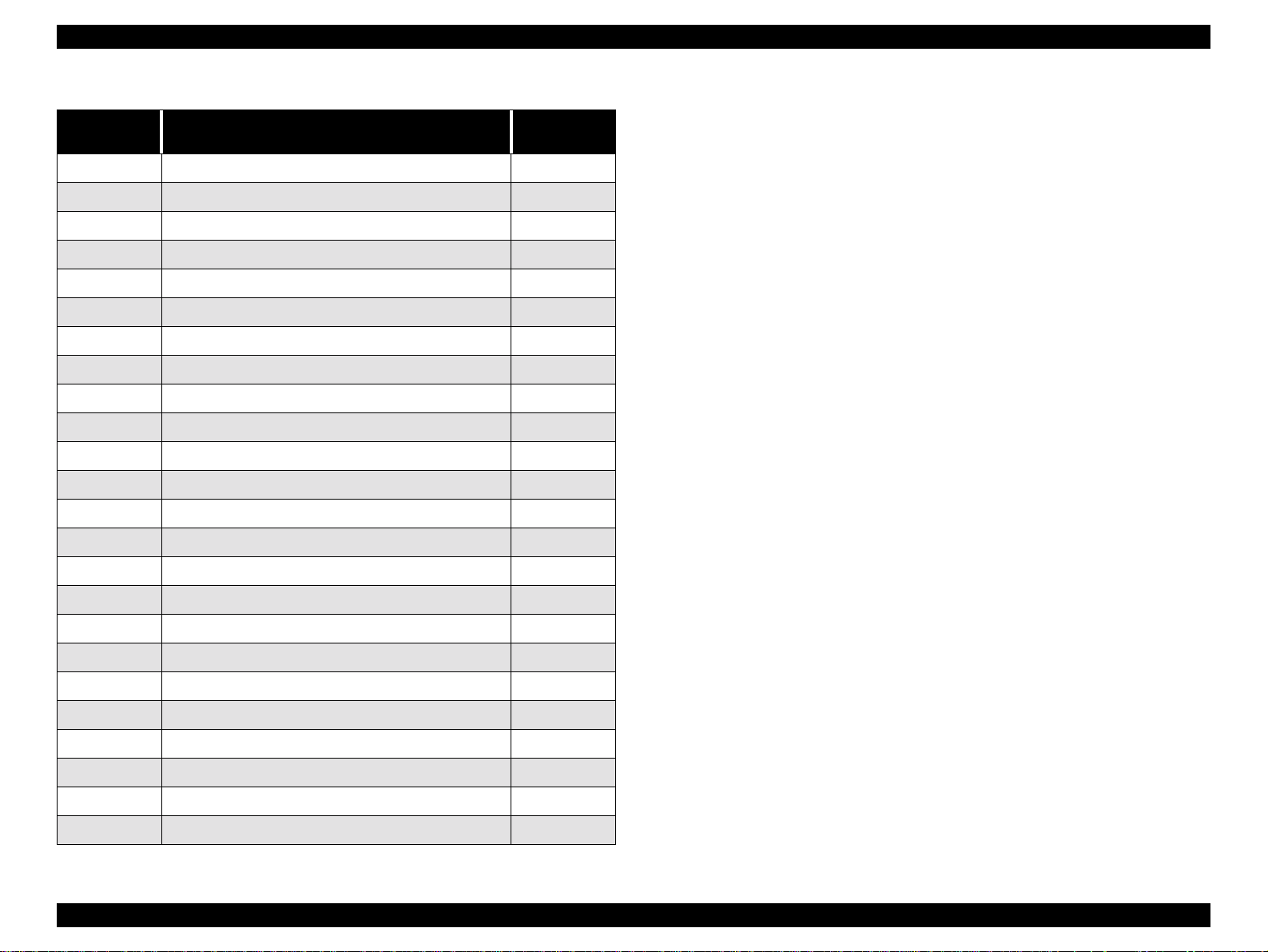
EPSON Stylus Pro 7500 Revision c
Table 3-23. Fatal Error Code List (continued)
Code Description
00010004 CR motor/ encoder check error (out of step error)
00010005 CR motor/motor out of step
00010006 CR motor/overcurrent
00010007 CR motor/ in position time-out error
00010008 Servo wa tchdog time-out er ror
00010009 System watchdog time-out error
0001000A CR home position sensor error
0001000B PF home position sensor error
0001000C Head slide (PG) home position sensor error
0001000D Cover open sensor error (00)
0001000E Cover open sen s or error (01)
0001000F CR motor/PWM output malfunction
00010010 PF motor/PWM output malfunction
00020000 NVRAM error
00020001 Internal RAM check error
Refer to
page
90
90
90
90
90
91
91
91
91
92
92
92
92
92
92
00020002 SRAM check error
00020003 DRAM check error
0002000B Mail box error (memory error)
10020004 CPU vector 4 general illegal instruction
10020006 CPU vector 6 slot illegal instruction
10020009 CPU vector 9 CPU address error
1002000A CPU vector 10 DMAC/DTC address error
1002000B CPU vector 11 watchdog time-out error
100200** CPU vector 3 2~63 (incorrect trappi ng)
92
92
88
88
88
88
88
88
88
Troubleshooting Troubleshooting Based on Error Display 87
Page 88

EPSON Stylus Pro 7500 Revision c
3.3 Errors That Require a Service Technician
Here, of the warnings and fatal errors mentioned in the previous item, the contents and
methods of treatment of those errors which require a service man are explained.
MAINTENANCE CALL 0100
Problem
o
The waste ink pads are almost full, causing a warning error. The printer can
continue printing, but this messages overrides status messages such as Ready or
Printing.
o Solution
Replace the following parts and reset the counters as described below
n
Waste Ink Pads
n
F Box
n
Pump Assembly
n
Cap Assembly
n
Cleaner, Head
NOTE: The above 5 parts can be suppli ed in th e periodic pa rts ki t “Maintena nce
Kit Stylus Pro 7500 (No. 1058463).”
SERVICE CALL 00000100
Problem
o
The waste ink pads are completely full, causing a fatal error. The printer stops
printing.
SERVICE CALL 00000101
Content
o
The carriage drive system has reached the end of its service life.
o Treatment
n
Check if the bends and joints of the ink supply tubes have damage, cracks or ink
leakage.
n
Check if the CR timing belt, driven pulley and CR motor are normal.
n
Check if the CR timing belt’s tension is normal.
n
If no abnormalities could be confirmed, carry out initialization of the CR motor’s
service life counter in Maintenance Mode 2.
SERVICE CALL 00010000
Problem
o
PF motor encoder check error
The PF motor makes small revolutions clockwise and counter-clockwise. When it
turns, the printer checks the rotary encoder (ins ide the motor) output signals to
make sure the motor is turning at the correct speed/distance. If the encoder sends
an incorrect signal, an error occurs.
o Solution
Check if there is an abnormal load, etc. on the rotation of the grid rollers. They
there is no abnormality and the error is still not cleared, check the PF motor
encoder. If it is abnormal:
n
Check and adjust the PF timing belt tension
n
Replace the PF motor
n
o Solution
Same as “Maintenance Call 0100.”
Replace the PF motor extension cable
n
Replace the C299MAIN Board
Troubleshooting Errors That Require a Service Technician 88
Page 89

EPSON Stylus Pro 7500 Revision c
SERVICE CALL 00010001
Problem
o
PF Motor out of Synch
Abnormal PF motor internal encoder output pulse width detected (Long or short
with respect to the specified time).
o Solution
Check if there is an abnormal load, etc. on the rotation of the grid rollers. They
there is no abnormality and the error is still not cleared, check the PF motor
encoder. If it is abnormal:
n
Check and adjust the PF timing belt tension
n
Replace the PF motor
n
Replace the PF motor extension cable
n
Replace the C299MAIN Board
SERVICE CALL 00010002
Problem
o
PF motor overcurrent
Feedback from the PF motor (IC35) driver’s 10-pin output (sensor signal)
indicates that the PF motor’s current is irregular.
o Solution
n
Replace the PF motor
n
Replace the PF motor extension cable
n
Replace the C299 MAIN Board
SERVICE CALL 00010003
Problem
o
PF motor in position time out
In the PF motor control, position control did not finish within the regular position
stabilization time (in position time) during stop processing.
o Solution
n
Replace the PF motor
n
Replace the PF motor extension cable
n
Replace the C299 MAIN Board
Troubleshooting Errors That Require a Service Technician 89
Page 90

EPSON Stylus Pro 7500 Revision c
SERVICE CALL 00010004
Problem
o
CR motor encoder check error
The CR motor makes small revolutions clockwise and counter-clockwise. Wh en it
turns, the printer checks the encoder output signals to make sure the motor is
turning at the correct speed/distance. If the enco der does n’ t s end the co rrect sign al
or output data, an error occurs.
o Solution
Make sure there is nothing blocking the carriage. If that does not solve the
problem, check the CR motor encoder connection. If there still is a problem, try
the following.
If there are abnormalities:
n
Check if the T fence for detection of the encoder pulse is removed
n
Check for dirt, paper dust or damage to the T fence
n
Replace the CR_ENC (carriage encoder) sensor
n
Replace the CR motor
n
Replace the C299 MAIN Board
SERVICE CALL 00010005
Contents
o
CR Motor out of Synch
Abnormal CR encoder output pulse width detected (Long or short with respect to
the specified time).
o Solution
Check if there is not some abnormal load during carriage movement. If there is no
abnormality, but the error is not cleared, check the CR motor encoder. If there are
abnormalities:
SERVICE CALL 00010006
Problem
o
CR motor overcurrent
Feedback from the CR motor (IC33) driver’s 10-pin output (Sense signal)
indicates that the CR motor’s current is irregular.
o Solution
n
Replace the CR motor
n
Replace the C299 Main Board
SERVICE CALL 00010007
Contents
o
CR Motor In Position Time Out
In the CR motor control, pos i t ion co nt rol did not fi n ish wi t hin t h e regul ar pos i t ion
stabilization time (in position time) during stop processing.
o Solution
n
Replace the CR_ENC (carriage encoder) sensor.
n
Replace the CR motor
n
Replace the C299 Main Board
SERVICE CALL 00010008
Problem
o
Servo interrupt watchdog time-out error due to motor-drive control related error
o Solution
Replace the C299 Main Board
n
Check if the T fence for detection of the encoder pulse is removed
n
Check for dirt, paper dust or damage to the T fence
n
Replace the CR_ENC (carriage encoder) sensor
n
Replace the CR motor
n
Replace the C299 MAIN Board
Troubleshooting Errors That Require a Service Technician 90
Page 91

EPSON Stylus Pro 7500 Revision c
SERVICE CALL 00010009
Problem
o
System interrupt watchdog time-out error due to sensor-related error
o Solution
Replace the C299 Main Board
SERVICE CALL 0001000A
Problem
o
CR origin sensor malfunction
CR home position sensor malfunction
o Solution
n
Replace the CR_HP detection sensor
n
Replace the C299 Main Board
SERVICE CALL 0001000C
Problem
o
The head SLID home position sensor is faulty
o Solution
Check if there is ink or dirt, etc. adhering to the sensor surface and hindering the
detection operation. If there is no abnormality and the error is not canceled, check the
SLID home position sensor.
If there are abnormalities:
n
Replace the head SLID detection sensor
n
Replace the C29 9 MAIN board
Troubleshooting Errors That Require a Service Technician 91
Page 92

EPSON Stylus Pro 7500 Revision c
SERVICE CALL 0001000D SERVICE CALL 0001000E
Problem
o
Cover Sensor Failure (00)/(01)
The cover open detection sensor (interlock switch) is abnormal.
n
(00): Right side sensor ..... Not installed in the Stylus Pro 7500.
n
(01): Left side sensor
o Solution
Check the sensor mounting position. If the error is not canceled by adjusting the
position to the proper place, check the cover open detection sensor.
If there are abnormalities:
n
Replace the malfunctioning cover sensor
n
Replace the C299 MAIN Board
SERVICE CALL 0001000F
Problem
o
CR motor PWM output error
o Solution
n
Replace the C299 MAIN Board
SERVICE CALL 00010010
Problem
o
PF motor PWM output error
o Solution
n
Replace the C299 MAIN Board
SERVICE CALL 00020000 (NVRAM ERROR)
SERVICE CALL 00020001 (INTERNAL RAM ERROR)
SERVICE CALL 00020002 (SRAM ERROR)
SERVICE CALL 00020003 (DRAM ERROR)
o Problem
Unusual condition detected.
o Solution
n
Make a note of the error code that was generated, turn on the power again and
check if the same error is generated again. If there is reproducibility, replace the
C299 MAIN Board.
SERVICE CALL 10000004
(CPU VECTOR 4 / GENERAL IMPROPER COMMAND ISSUED)
SERVICE CALL 10000006
(CPU VECTOR 6 / SLOT IMPROPER COMMAND)
SERVICE CALL 10000009
(CPU VECTOR 9 / CPU ADDRESS ERROR)
SERVICE CALL 1000000A
(CPU VECTOR 10 / DMAC/DTC ADDRESS ERROR)
SERVICE CALL 1000000B
(CPU VECTOR 11 / WD TIMER OUT ERROR)
SERVICE CALL 10000 ** (CPU VECTOR 32 ~ 63)
o Problem
n
Make a note of the error code of the error that occurred, turn on the power again
and check if the same error is generated again. If there is reproducibility, replace
the C2999MAIN board.
n
Check if there are differences in the occurrence of errors according to print data
(size, print mode, etc.).
Troubleshooting Errors That Require a Service Technician 92
Page 93

EPSON Stylus Pro 7500 Revision c
n
3.4 Troubleshooting Based on Your Printout
This section describes conceivable print quality problems that may occur with this printer
and the troubleshooting points for those errors.
Table 3-24. Diagnosing trouble based on printout
Description Refer to
Dot missing
Uneven printing/poor resolution
Smudged or marre d printout on front side
Smudged or marre d printout on reverse side
White/black banding
page 93
page 94
page 94
page 95
page 95
If the cap assembly / pump tubes have come off.
n
If the gear train between the pump motor and pump unit has been misassembled.
n
If the cap assembly has faile d. (The tens ion s pr ing has com e off, th e cap rubb er is
damaged, etc.)
n
If the pump unit has failed. (The tubes are crushed, etc.)
b) If the trouble occurs with a specific ink color:
n
Abnormal connections between the ink cartridge, ink holder, tube, damper, print
head. (Fastening nuts loose, or the O-ring deformed or damaged, causing ink to
leak, etc. could occur.)
n
Print head failure
Left side (B Head) Black, Cyan, Magenta
Right Side (C Head) Light Cyan, Light Magenta, Yellow
DOT MISSING
If the printer is kept for a long time without being used, the viscosity of the ink on the
nozzle surfaces of the print heads, and in the nozzles themselves, increases, and may cause
skipping of dots during printing. After cleaning, (clean several times), if the printer still
doesn’t recover from skipping dots, the following points sho uld be checked.
1. After executing the “Inter-user Transport Mode,” set the “Transport Liquid Cartridges
(x 6 cartridges)” in place of ink cartridges and carry out initial filling. (The ink
passages will be completely cleaned by the transport liquid.)
After initial filling with the transport liquid, discharge the transport liquid from the
printer in the “Inter-User Transport Mode.” After that, set new ink cartridges and carry
out initial filling, then carry out “Nozzle Check Pattern Printing.”
CAUTIO N
2. If the operation in “1” fails to bring recovery, check the following points.
a) If trouble occurs in all the ink colors:
n
Initial filling causes a large amount of fluid to be discharged into the
waste ink pad, so the “Waste Ink A,” “Waste Ink B” and “Cleaner”
counters will show considerable consumption. (approximately 10%).
Are the print heads and cap assemblies sealed during ink filling?
c) If the trouble still has not been recovered from with the items up to this point,
replace the following electric system related parts and check again.
n
Check the connections to the CR cable (FFC long) and if there is any damage to it
or not.
n
Check the connections to the head cables (FFC short; x 2), and if there is any
damage to them or not.
n
The C299MAIN board.
CAUTIO N
n If you replace the C299MAIN board or the print heads, the
connection state of the connection cables (FFC) should be
checked. Particularly in cases where the connector is inserted at
a slant, etc., when the power is turned on, it could cause
destruction of the circuit and the insides of the heads, so
sufficient caution should be exercised.
n During head replacement, care should be taken not to mistake
the B head and C head.
Troubleshooting Troubleshooting Based on Your Printout 93
Page 94

EPSON Stylus Pro 7500 Revision c
UNEVEN PRINTING/POOR RESOLUTION
If the print quality is abnormal (uneven printing, diffused image, etc.), the following items
should be checked.
1. Adjust the gap
Using panel settings or the self-diagnostic function, carry out gap adjustment (“round
trip print position adjustment” and “gap adjustment”).
2. If the trouble occurs only when the user is using a specific type of paper (thick paper),
carry out “User Paper Setting” using the panel setting procedure.
(By setting the information concerning the thickness of the paper the user is using and
correcting the print position (correction of changes in the position where ink hits the
paper surface due to differe nce s in pape r thickn e ss), av oid influe n cing the print
position.)
3. Try changing the Bi-D offset #1 (speed priority) / #2 (quality priority) correction
values in [Maintenance Mode 2].
4. If this trouble occurs immediately after replacing the C299MAIN board with a new
one, transfer the backup parameters from the old C299MAIN board to the new one.
Execute “Write D/A Correction Values” in the diagnostic mode.
5. If the printer’s condition is not improved by the above items (adjustments), check the
following items using the self-diagnostic function.
n
Head tilt adjustment
n
Head height adjustment
SMUDGED OR MARRED PRINTOUT (FRONT)
If smudging or marring occurs due to rubbing by the head, etc. on the paper’s printed
surface, check the following items.
1. If smudging is occurring at the front end of the roll paper or at the rear end, widen the
margins at the front end and rear end. (Set the “Roll Paper Margin” front end and rear
end on “15 mm”.)
(If high duty printing was done close to the front end and rear end (margin = 3 mm),
the paper will contain a large amount of ink and deformation of the paper will be
accelerated, and depending on the case, the paper will touch the heads.)
2. If paper with weak edges which cannot move smoothly along the paper path is being
used, Select “NORM” for “SUCTION” in the “PAPER CONFIG. MENU”, which is in
the “Panel Settings”.
3. If there is rubbing and smudging due to slow drying in printing of user paper.
n
Set the stand basket paper Eject direction on Front.
n
In the item “DRYING TIME” in the User Paper Setting Menu”, in “Panel
Settings,” set the drying time (the time until auto paper cutting is carried out after
printing is finished (the default is 0 min. The maximum is 30 min.).
4. If the trouble cannot be resolved by the above methods, check the following.
n
The cap assembly / tension spring is off.
(If this spring comes off, cap will collect inside the cap and ink that adheres
around the head nozzle surface ends up adhering to the paper.
CHECK
PO IN T
If you have performed the “Head tilt adjustment” or “Head height
adjustment,” be sure to carry out the “Round trip print position
adjustment” and “Gap adjustment.”
Troubleshooting Troubleshooting Based on Your Printout 94
Page 95

EPSON Stylus Pro 7500 Revision c
SMUDGED OR MARRED PRINTOUT (REVERSE SIDE)
If smudging or marring of the paper back surface with ink occurs, the following items
should be checked.
1. Check if there isn’t ink adhering to the paper feed path. If there is ink adhering, it
should be wiped off.
n
Sub-platen A/B Surface
n
Grid roller surface
n
Paper guide L surface
n
Paper guide L2 surface
2. One likely cause of ink adhering to the above parts is the following cause.
n
Paper feeding at a slant during printing (at the point when 1 page is finished)
CAUTIO N
n If the Paper Skew Detection setting is off in “Printer Settings” ->
“Panel Setting Menu” -> “Paper Width Detection,” if the user’s
paper size setting is not correct, the surface of the platen will be
printed.
WHITE OR BLACK BANDING
If white or black banding (lines across the page) appear on your printout, try the following.
1. Print the “Nozzle Check Pattern.”
If it is normal, carry out the “Head Slant Adjustment.”
If skipping of dots occurs, carry out “Cleaning.”
2. If skipping of dots is not the cause, carry out adjustments of the print heads.
Head slant adjustment (B head / C head)
n
If each of the nozzle rows on the B head or C head is not positioned so that it is
perpendicular to carriage travel direction, overlapping of the raster lines which are
printed and compose the print will occur, and this will cause dense portions and
white streaks between raster lines.
n
Head height adjustment (B and C heads)
n
Round trip print position adjustment.
n
Gap adjustment.
n
In the self-diagnostic mode, check if the value written for the head ID.
Troubleshooting Troubleshooting Based on Your Printout 95
Page 96

DISASSEMBLY & ASSEMBLY
CHAPTER
Page 97

EPSON Stylus Pro 7500 Revision c
4.1 Summary
This section describes the disassembly and assembly methods for the EPSON Stylus Pro
7500. However, full assembly instructions are not given apart from following the
disassembly instructions in reverse order, and where special instructions are necessary,
reassembly points are provided.
Where “Caution” and “Reassembly” notes are given, be sure to confirm these contents
BEFORE starting the corresponding procedure. Where adjustment procedures are
necessary, “Adjustment Required” notes describe what you need do to. These adjustment
procedures are absolutely necessary and are described in detail in Chapter 5.
4.1.1 Warnings
Before proceeding with any disassembly or assembly work, make absolutely sure of the
following.
W ARNING
n The power switch is located on the control panel. Any time the
printer is plugged into a power outlet, power is flowing through
the PS board. Unless otherwise stated, always turn off the
printer, wait several seconds, and then unplug t he po wer cable
from the outlet before servicing a printer.
n Wear protective goggles to protect your eyes from ink. If ink gets
in your eye, flush the eye with fresh water and see a doctor
immediately.
n Wear a pair of gloves to protect your hands than the sharp edge
in the printer mechanism.
n For safety reasons, the front cover position is automatically
detected by the cover-open sensor which is an interlock switch.
Do not block or modify this sensor.
n A lithium battery is installed on the MAIN Board of this printer.
Be sure to observe the following instructions when servicing the
battery:
n
Keep the battery away from any metal or other batteries so that
electrodes of the opposite polarity do not come in contact with each
other.
n
Do not install the battery in the wrong direction. (This may cause
burning or explosion.)
n
Do not heat the battery or put it near fire.
n If ink gets on your hands, wash them thoroughly with soap and
water. If ink gets in your eyes, rinse them immediately with
water.
Disassembly & Assembly Summary 97
Page 98

EPSON Stylus Pro 7500 Revision c
CAUTIO N
n Before servicing or performing maintenance on the printer,
make sure you have enough space. If you need to move the
printer, be sure the space you move to is safe.
n Because the printer is much heavier than most printers (about
43.5Kg for the printer body/ 52Kg for the printer and stand), you
need to take extra care. If you need to take apart the printer and
stand or lift the printer, two people are necessary.
n If you remove the ink path system parts and replace them, run
the “Inter-User Transport Mode” and discharge the ink.
n As necessary, after discharging the ink using the above method,
carry out ink initial filling using the “Transport Fluid Cartridges
(x 6 cartridges), then discharge the transport fluid in the InterUser Transport Mode to clean the ink system even more
thoroughly.
n After removing any of the ink related parts, double check to
make sure all parts are secured; otherwise you’re going to be in
big trouble.
n Ink may leak onto other printer parts or the printer basket when
removing printer parts, so it is recommended to put a sheet or
cloth under the printer, especially when working on or near inkrelated parts.
n When working on the electrical circuit boards, be careful
concerning static electricity which can cause damage to the
board. It is recommended you use an anti-static wrist band or
similar grounding device to prevent static electricity buildup.
n When removing/re-inserting the flat-cable (FFC) from/to a
connector, make sure to pull/insert the cable at a 90 degree angle
to the connector. Otherwise, internal contact of the leads may be
damaged and this can cause a short-circuit.
n When replacing connector wires, be careful to replace the entire
length of the wire exactly as you found it; rubbing against edges
or moving parts can cause noise in the wires.
n As necessary, if you remove each cover operate the printer, care
should be taken not to get injured by the operation of the drive
system units.
n The cutter blade is extremely sharp, so care should be taken not
to injure yourself when handling it.
n An ultra-hardened blade is used for the cutter blade, and
physically, it is extremely brittle material, so care should be
taken not to bump it against any of the metal parts of the printer,
etc. and damage it.
n When performing service operations on items which are
controlled as after service parts but which no procedures have
been provided for, the state of the parts should be observed
closely before beginning the operation to get a thorough idea of
how to proceed.
n See the drawing at right concerning directions during repair
operations.
n If you have to loosen a screw that has blue screw-lock applied to
its head, make sure you apply blue screw-lock again when
reassembling.
Top
L
Front
Bottom
Rear
R
Figure 4-1. Directional View of the Printer
Disassembly & Assembly Summary 98
Page 99
EPSON Stylus Pro 7500 Revision c
4.1.2 Tools
This section lists the tools necessary to disassemble or assemble the printer.
Table 4-1. Necessary Tools
Tool Part Code Notes
(+) Phillips screwdriver #2
(+) Phillips screwdriver #1
(-) Standard screwdriver
Round-nosed pliers
Tweezers
#E 589 Torqu e Wrench (6 mm
x 1.0 kg) or #f760 Torque
Wrench
commonly available tools,
no special tools necessary
B765106901
1059914
longer than 250mm is helpful
-
-
-
For tube and joint screws.
Hex Wrench
PF Loop Scale ASSY
Assembly tool
PF Loop Scale Attachment
tool
Ink Cartridge L T ransport
Fluid, S46, Recy cled
Maintenance Kit, Stylus Pro
7500
Part with Exclusive Stand
(Commercially available
part)
1051765 Exclusive tool No. #f730
1051767 Exclusive tool No. #731
1045585 Transport liqu id cartri dg e *2
1058463 Periodic Replacement Parts Kit
5.5mm*1
NOTE: This hex wrench is necessary only when removing the stand.
NOTE: 6 of these cartridges are necessary for one operation.
Disassembly & Assembly Summary 99
Page 100

EPSON Stylus Pro 7500 Revision c
4.1.3 Screw List
The following table lists all the screws used in this printer.
Table 4-2. Screws
Type Color Description
CB M3x6
CBP M3x6
CBP M4x10
CBS M3x10
CBS M4x6
CBS M2x8
CBS M3x6
CBS M4x8
CBS M3x10
CUPS M3x6
CUPS M4x6
CUPS M4x8
CPP M3x8
CPS M3x12
CP M3x6
CP(W) M2x12
CP(W) M2x8
CP(W) M3x6
CP(W)M3x8
CP(W)M3x25
CP(W)M4x8
CP(W)M4x10
CP(W)M4x40
Dish screw M3x6
white
silver
black
white
white
white
white
white
white
white
white
white
white
white
white
silver
silver
silver
silver
silver
silver
silver
silver
white
(+) Bind
(+) Bind P-tight
(+) Bind P-tight
(+) Bind S-tight
(+) Bind S-tight
(+) Bind S-tight
(+) Bind S-tight
(+) Bind S-tight
(+) Bind S-tight
(+) Cup S-tight
(+) Cup S-tight
(+) Cup S-tight
(+) Crosshead Pan P-tight
(+) Crosshead Pan S-tight
(+) Crosshead Pan
(+) Crosshead Pan, washer
(+) Crosshead Pan, washer
(+) Crosshead Pan, washer
(+) Crosshead Pan, washer
(+) Crosshead Pan, washer
(+) Crosshead Pan, washer
(+) Crosshead Pan, washer
(+) Crosshead Pan, washer
(+) Dish
Type Color Description
Truss screw M4x6
Toothed washer M3
Toothed washer M4
Table 4-2. Screws (continued)
white
white
white
(+) Truss screw
outer teeth
outer teeth
Disassembly & Assembly Summary 100
 Loading...