

Page 1
Page 2
About The Manuals and Notations Used
Types of Manual
The documentation for your EPSON projector is divided into the following four manuals. Refer to the
manuals in the order given below.
Unpacking and Installation Guide
This manual contains information on the procedures from unpacking the projector through to starting to use the
projector, and also describes the included accessories.
Safety Instructions/World-Wide Warranty Terms
This manual contains information on using the projector safely, and also includes safety instructions ,worldwide warranty terms and a troubleshooting check sheet.
Be sure to read this manual thoroughly before using the projector.
Setup Guide
This manual describes the preparations required in order to start using the projector (such as remote control
preparation and connecting video equipment or a computer).
User’s Guide (this manual)
This User’s Guide contains information on basic operation, using the projector menus, troubleshooting and
maintenance.
Notations used in this User’s Guide
General information
Indicates procedures where personal injury or damage to the projector may occur if t he
procedures are not followed correctly.
Indicates additional information and points which may be useful to know regarding a topic.
Indicates that an explanation of the underlined word or words in front of this symbol appears
in the glossary of terms.
Refer to the “Glossary” in the “Appendix”. (p.59)
Procedure
Indicates operating methods and the order of operations.
The procedure indicated should be ca rried out in the order of the numbers.
Meaning of "unit" and "projector"
When "unit" or "projector" appears in the text of this User’s Guide, they may refer to items which are
accessories or optional equipment in addition to the main projector unit itself.
Page 3
Contents
Features of the Projector .................. ... ..............................................................2
Basic Operations
Turning On the Projector....................................................................................6
Connecting the Power Cord .....................................................................................6
Turning On the Power and Projecting Images..........................................................7
Turning Off the Projector....................................................................................8
Adjusting the Screen Image ............................................................................10
Adjusting the Image Size .......................................................................................10
Adjusting the Image Angle ....................................................................................10
Correcting Keystone Distortion..............................................................................11
Displaying a Test Pattern........................................................................................12
Adjusting the Image Quality.............................................................................13
Focusing the Screen Image.....................................................................................13
Selecting the Color Mode.......................................................................................13
Selecting the Image Aspect Ratio ..........................................................................14
Automatic Adjustment of Computer Images .........................................................16
Advanced Operations
Functions for Enhancing Proje ctio n........................... ... ... ...................... ..........18
Using the Environment Setting Menus...................................................................18
Description of Functions........................................................................................21
Saving and Retrieving Image Quality Settings (Memory).....................................22
Using the Menu Functions...............................................................................24
Video Menu............................................................................................................25
Advanced Menu .....................................................................................................29
Setting Menu.......................................................................................................... 30
About Menu.................................................. ........ ..................................................31
Reset All Menu.......................................................................................................32
Basic OperationsAdvanced OperationsTroubleshootingAppendices
Troubleshooting
Using the Help .................................................................................................34
When Having Some Troub le............................................................................35
When the Indicators Provide No Help..............................................................37
Appendices
Maintenance....................................................................................................44
Cleaning .................................................................................................................44
Replacing Consumables....................................................... ..................................45
Optional Accessories.......................................................................................49
List of Supported Signal Resol u tio n s ............ ... ... ...................... ......................50
Component Video Input.........................................................................................50
Composite Video/S-Video Input ............................................................................50
RGB Input..............................................................................................................51
Specifications ..................................................................................................52
Appearance .....................................................................................................54
Part Names and Functions..............................................................................55
Front/Top................................................................................................................55
Control Panel..........................................................................................................56
Rear ........................................................................................................................57
Base........................................................................................................................57
Remote Control......................................................................................................58
Glossary ..........................................................................................................59
Index................................................................................................................61
1
Page 4
Features of the Projector
(p
)
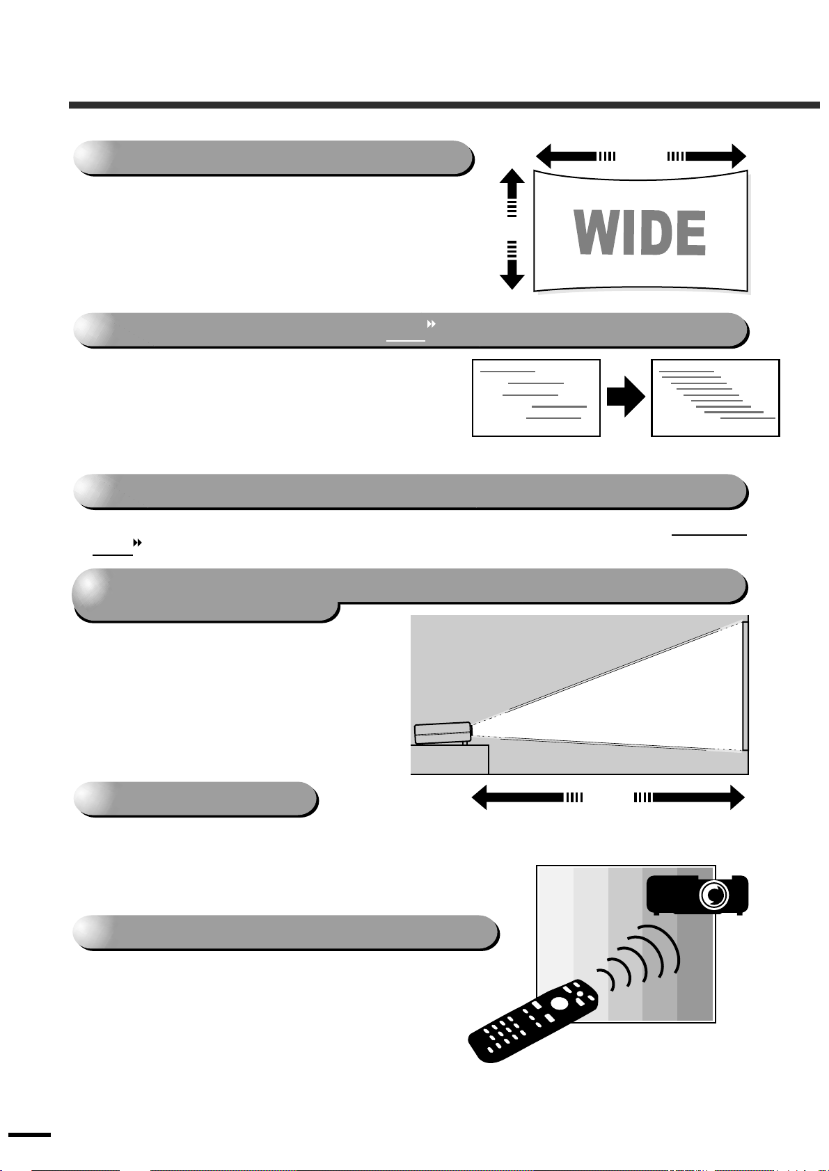
Adoption of a wide 1280 x 720 dot panel
1280
This panel allows high-definition images to be
reproduced accurately.
720
Adoption of a special high-resolution DCDi video circuit developed by Faroudja.
This circuit greatly reduces the jagged edges that
resulted from conventional progressive conversion,
to produce much smoother and natural movement.
(p.29)
Adoption of a three-dimensional Y/C separation function in the video processing circuit
This greatly reduces the noticeable color interference at the color boundaries of composite
video signals, resulting in sharper and smoother reproduction of images.
Adoption of a short focal-length lens that can project onto 80-inch screens
at distances of 2.5m (8.2 ft.)
This lens is ideal for projecting onto large
indoor screens. The projector can also
project onto 100-inch screens in rooms
2
with an area of about 10 m
.
80-inch
screen
(Refer to the Setup Guide.)
Uses five color modes
2.5m
You can select the desired color mode to match the
images being projected from five preset modes in order
to obtain the optimum image quality.
(p.13)
Includes a variety of color adjustment modes
Various color settings can be adjusted to suit
your preferences, from individual RGB balance
adjustment to setting the color temperature of
your choice. The adjusted settings can then be
stored in memory and recalled at a touch of a
button on the remote control.
.26, 28
2
Page 5
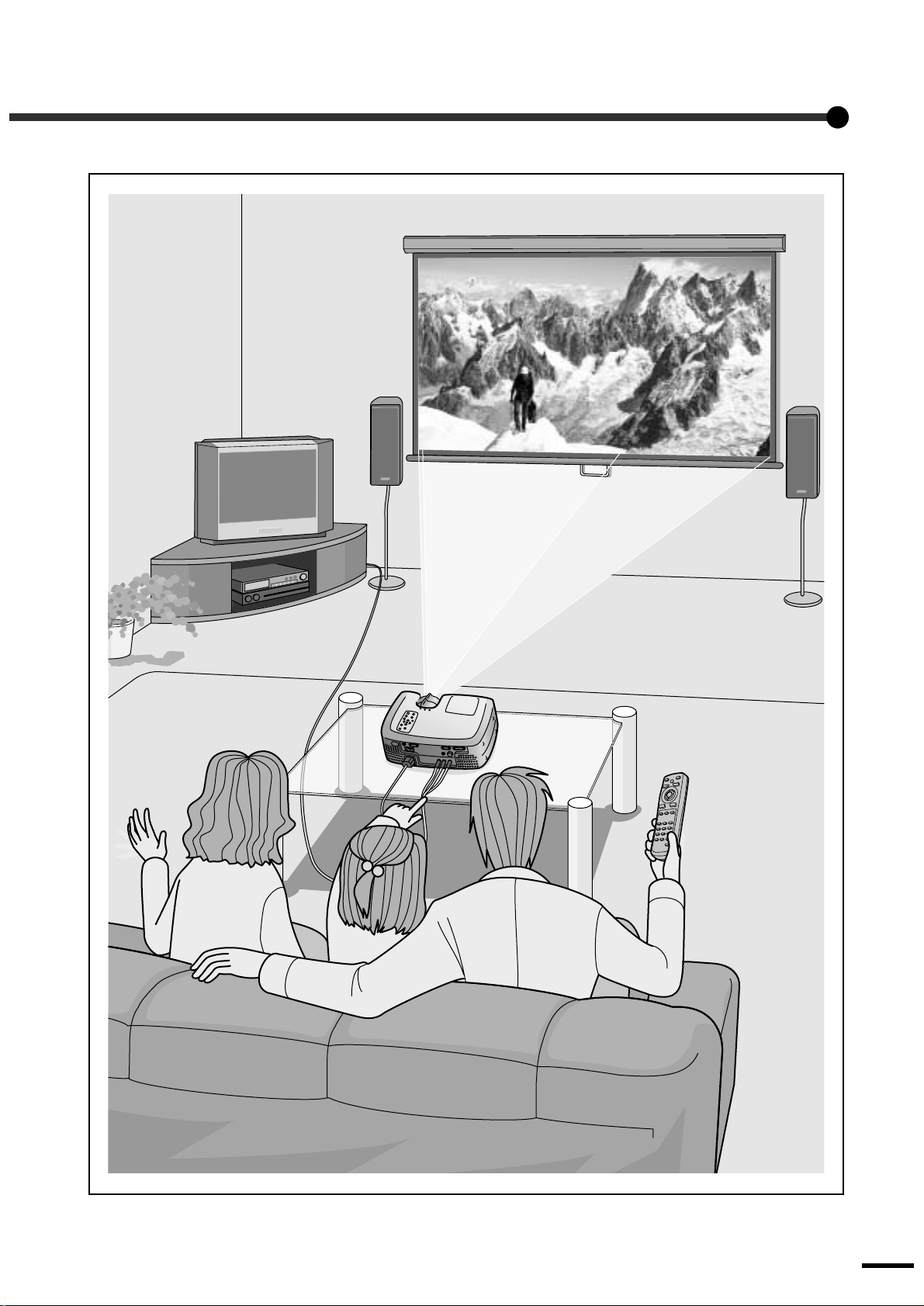
*Speakers are not included with the projector and must be purchased separately.
3
Page 6

Page 7

Basic Operations
This chapter describes basic operations such as turning
the projector on and off a nd adjusting t he projected images.
Turning On the Projector...................................6
•••• Connecting the Power Cord ...............................................6
•••• Turning On the Power and Projecting Images..................7
Turning Off the Projector...................................8
Adjusting the Screen Image............................10
•••• Adjusting the Image Size ..................................................10
•••• Adjusting the Image Angle...............................................10
•••• Correcting Keystone Distortion .......................................11
•••• Displaying a Test Pattern..................................................12
Adjusting the Image Quality............................13
•••• Focusing the Screen Image...............................................13
•••• Selecting the Color Mode..................................................13
•••• Selecting the Image Aspect Ratio.....................................14
• Normal mode .....................................................................................14
• Squeeze mode ....................................................................... .............15
• Zoom mode........................................................................................15
• Through mode....................... .............................................................15
• Squeeze Through mode ............ ........................ .................................15
•••• Automatic Adjustment of Computer Images..................16
5
Page 8
Turning On the Projector
This section describes the procedure from turning on the power to projecting images.
Be sure to read the separate
points that must be noted before using the projector to project images.
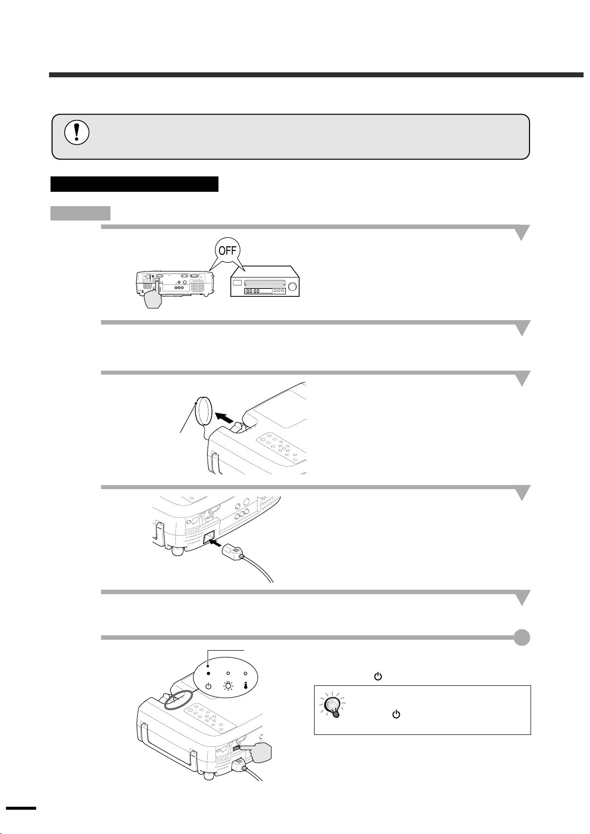
Connecting the Power Cor d
Procedure
1
2
3
Safety Instructions/World-Wide Warranty Terms
Check that the power is turned off for
the projector and all components
connected to t he projector.
Connect the computer or other video
source to the projector.
Refer to the Setup Guide.
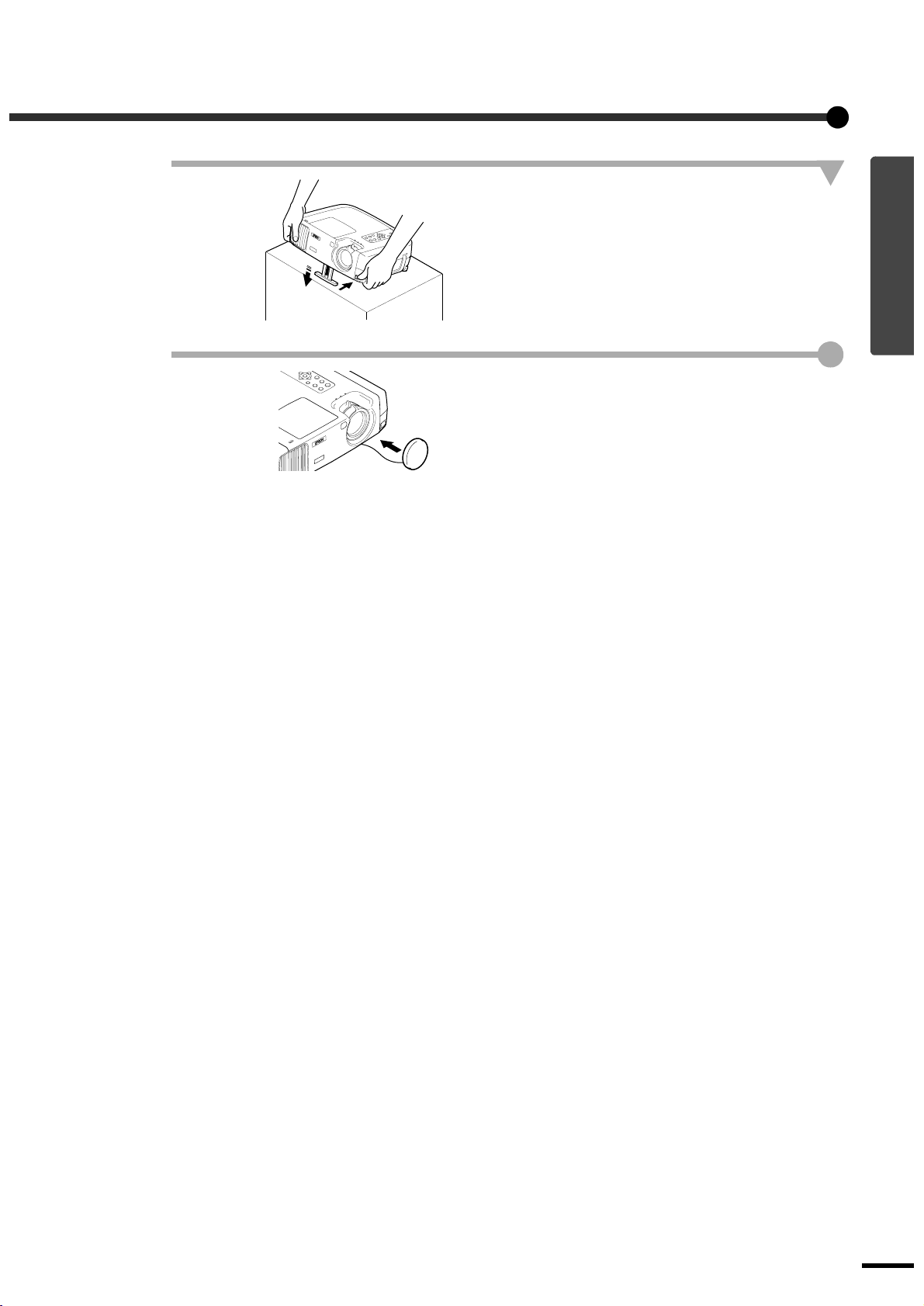
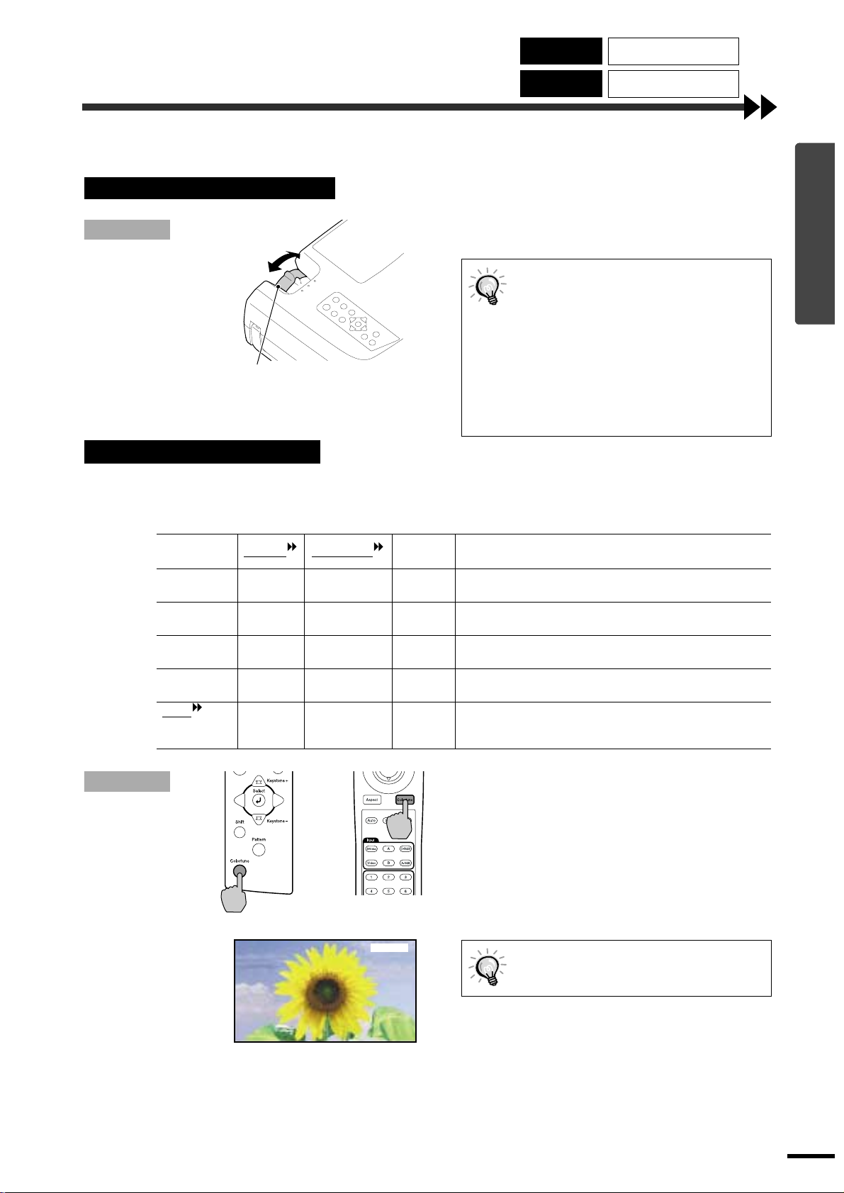
Remove the lens cover.
and check the
Place your f inger
under the top of the
lens cover and pull
to remove the cover.
4
5
6
Lights orange
Connect the acces sory power cor d to
the projector.
Check that the power co rd connector is f acing the
same way as the po wer inlet on the projector, and
then insert the power cord connector securely into
the projector.
Connect the other end of the power
cord to a grounded electrical outlet.
Turn on the main power switch at the
rear of the projector.
Wait until the indicator lights orange.
The buttons on the projector con trol panel
and remote control cannot be operated
while the indicator is flashing orange.
Wait until it lights steadily.
6
Page 9
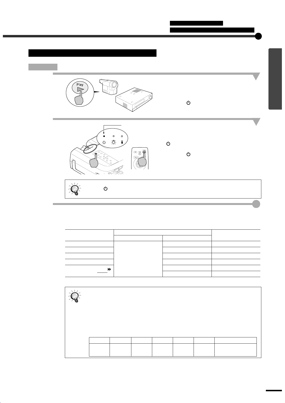
Turning On the Power and Projecting Images
Procedure
1
Connecting the Power Cord
Turning On the Power and Projecting Images
Turn on the power for all equipment
connected to the projecto r.
For a video source, press the [Play] button at the
video source to start playback if necessary.
Check that the indicator on the projector has
stopped flashing and lights orange.
Lights green
2
Press the [Power] button on either the
remote control or the projector's
control panel to turn on the power.
The indicator flashes green, and after a short
period projection starts.
Check that the indicator has stopped flashing
and lights green. (This takes approximately 15
seconds.)
Remote control
The buttons on the remote control and the projector's control panel cannot be operated
while the indicator is flashing green. Wait until it lights steadily.
The message "No-Signal." may appear depending on the projector's menu settings. (p.30)
If more than o ne signal sour ce has be en conn ected, use the remo te cont ro l or
3
control panel buttons to select the port which the signal source th at you
would like to use is connected to, while referring to the following table.
Port
InputA
InputB [B] INPUT B
S-Video [S-Video] S Video
Video [Video] Video
D-RGB/A-RGB DVI-I
[Source]
Projector Remote control
Button to press
[A] INPUT A
[D-RGB] D-RGB
[A-RGB] A-RGB
*The display disappears after 2 seconds.
Display at top-right of
Basic Operations
screen *
If only one signal source has been connected, the signals from that source will be
••••
projected without needing to press one of the above buttons.
If the "No-Signal." message does not disappear, check the connections again.
••••
If a laptop computer or a computer with an LCD screen has been connected to the
••••
projector, the images may not be projected straight away. After making the connections,
check that the computer has been set up to output signals.
The following table shows examples of how to toggle output settings. For details, refer to
the section of the documentation provided with your computer under a heading such as
"External output", "Connecting an external monitor" or similar.
NEC Panasonic Toshiba IBM Sony Fujitsu Macintosh
[Fn]+[F3] [Fn]+[F3] [Fn]+[F5] [Fn]+[F7] [Fn]+[F7] [Fn]+[F10]
After startup, change the
Control Panel adjustments
so that Mirroring is active.
7
Page 10
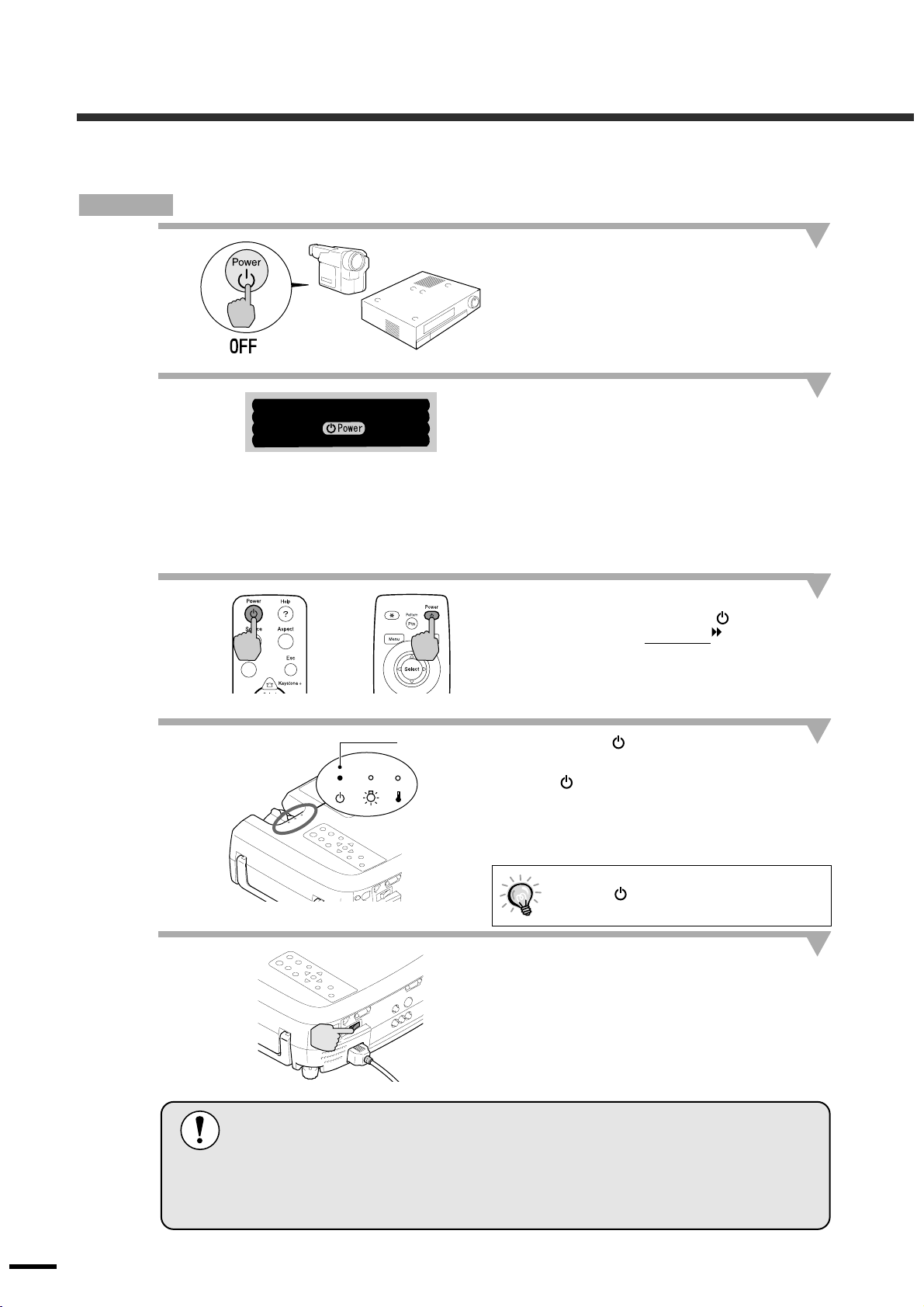
Turning Off the Projector
Follow the procedure below to turn off the power of the projector.
Procedure
1
2
3
Power OFF?
Please press key again
to power off.
Turn off the power for the signal
sources that are connected to the
projector.
Check that the power for all connected
components has been tuned off.
Press the [Power] button on either the
remote control or the projector's
control panel.
The confirmation message shown at left will
appear.
If you do not want to turn off the power, press
any button except the [Power] button.
If you do not carry out any operation, the
message will disappear after seven seconds. (The
power will not turn off at this time.)
Press the [Power] button once more.
The lamp unit will turn off and the indicator
will flash orange as the cool-down
starts.
period
4
5
Projector
Do not turn off the main power switch at the rear of the projector while the cool-down
is in progress. If the main power switch is turned off before cool-down is complete,
wait for the lamp to cool down (normally about one hour is required) before turning
the power back on again. If the power is turned off and on before the lamp has
cooled down, it may result in lamp operating errors.
Refer to "Lamp operating error" on page 35.
Remote control
Lights orange
Check that the indicator has changed
to light ora nge.
When the indicator lights orange, cool-down is
complete.
The cool-down period lasts for approximately 2
minutes. (This varies depending on factors such
as the ambient air temperature.)
The projector buttons cannot be operated
while the indicator is flashing orange.
Wait until it lights steadily.
If not using t he projector for long
periods of time, turn off the main power
switch at the rear of the projector.
8
Page 11
6
Retract the front adjustable foot if it is
extended.
Gently push down on the projector while pressing
the foot adjust button.
7
Attach the l e ns cover.
Attach the lens cover to the lens when not using
the projector, in order to stop the lens from
getting dusty or dirty.
Basic Operations
9
Page 12
Adjusting the Screen Image
You can adjust the screen image in order to obtain the best possible picture.
Adjusting the Image Size
The size of the projected image is basically determined by the distance from the projector to the screen.
(Refer to the Setup Guide.)
The following procedures explain how to adjust the screen image once the projector itself has been set up.
Procedure
Turn to Wide to
increase the size
Zoom ring
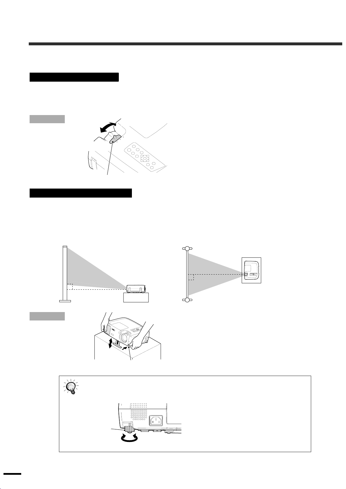
Adjusting the Image Angle
The projector should be as perpendicular to the screen as possible.
If the projector cannot be set up so that it is exactly perpendicular to the screen, it can be set up so that it is
tilting slightly horizontally or vertically. To tilt the projector upward, adjust the front adjustable foot to tilt the
projector at an angle of up to a maximum 12°.
Seen from the side
Turn to Tele to
reduce the size
Turn the zoom ring on the projector to
adjust the image.
The image can be enlarged in this way to 1.35
times the normal size.
If you would like to enlarge the image further,
move the projector further away from the screen.
(Refer to the Setup Guide.)
Seen from above
10
Procedure
While pressing the foot adjust button ,
lift up the front of the projector so that
the front adjustable foot can extend.
Extend the front adjustable foot until the desired
angle is obtained, and then release the foot adjust
button.
To retract the foot, press and hold the foot adjust
Foot adjust button
When the foot is adjusted, it may cause the projected images to become distorted. Use the
••••
keystone correction function to adjust this distortion. (p.11)
If the projector is tilted horizontally, adjust by turning the rear adjustable foot.
••••
Rear
adjustable foot
Extend
Retract
button and gently lower the projector.
Page 13
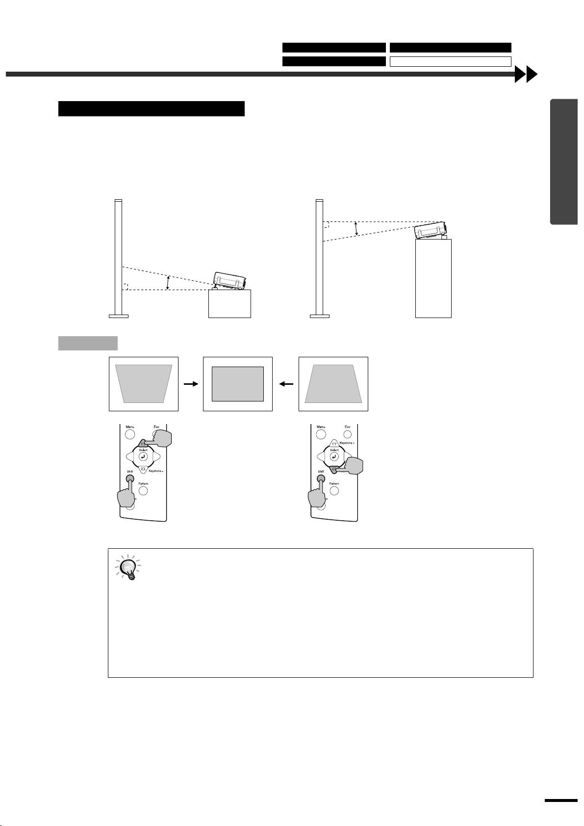
Correcting Keystone Distortion
If the projector is set up so that it is at an angle to the screen, a type of distortion known as "keystone
distortion" may occur.
Keystone correction can be carried out if the angle of the projector is within a range of approximately 15°
vertically from the perpendicular.
Adjusting the Image Size Correcting Keys tone Distortion
Adjusting the Image Angle Displaying a Test Pattern
Procedure
Approx. 15° above
Approx. 15° below
15°
15°
Basic Operations
While holding down the [Shift]
button on the projector's
control panel, press the
[Keyst one +] or [Keystone -]
button.
Projector Projector
When keystone correction is carried out, the projected image will become smaller.
••••
The keystone correction settings are memorized, so that if you change the position or angle of
••••
the projector, you may need to readjust the keystone correction settings.
If the images become uneven in appearance after keystone correction is carried out, decrease
••••
the “Sharpness” setting. (p.25, 27)
Keystone correction can also be carried out using the projector’s environment setting menu.
••••
(p.30)
If the value displayed in the gauge on the screen stops changing when horizontal or vertical
••••
keystone correction is being carried out, it indicate s that the lim it for horizontal or vertical
keystone correction has been exceeded. Check that the projector has not been set up at an
angle which exceeds the proper limit.
11
Page 14
Adjusting the Screen Image
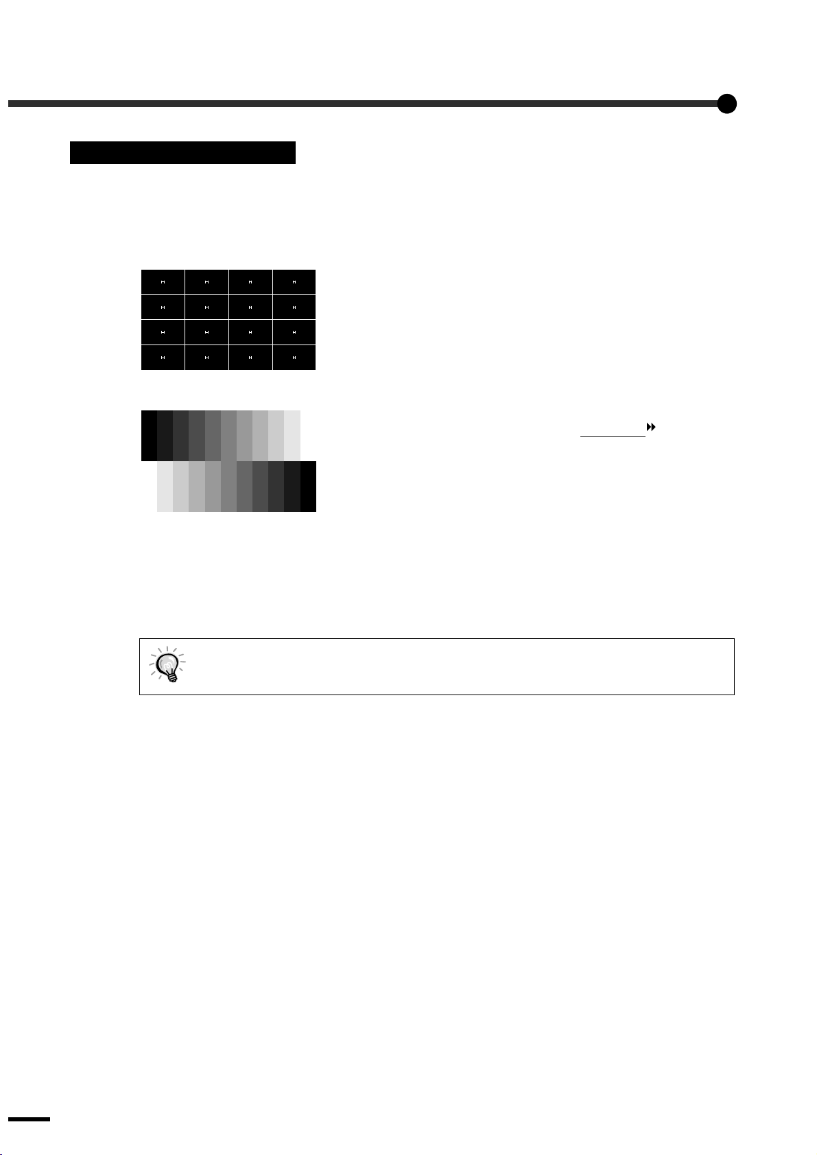
Displaying a Test Pattern
When setting up the projector, you can proj ect a test pattern onto the screen and use this test pattern to adjust
the projected images before a video source has been connected. The following two types of test pattern are
available.
Crosshatch
••••
Grayscale pattern
••••
This can be used to adjust the focus and correct keystone distortion.
This can be used to adjust dark and light shades to the desired shade.
The adjustment can be carried out using the "Color Temp
" or "RGB"
setting in the "Color Adjustment" item of the projector's "Video" menu.
The test pattern changes as shown below each time the [Pattern] button on either the remote control or the
projector's control panel is pressed.
Crosshatch → Grayscale pattern → No pattern
The full environment setting menu cannot be displayed while a test pattern is being projected. If
you need to change a setting, use the line menu or the [Keystone] buttons on the projector's
control panel.
12
Page 15
Adjusting the Image Quality
The quality of the screen images can be adjusted as follows.
Focusing the Screen Image
Focusing the
Screen Image
Selecting the Color Mode
Selecting the Image
Aspect Ratio
Automatic Adjustment
of Computer Images
Procedure
Focus ring
Selecting the Color Mode
The following five color modes have been preset for use with images with varying characteristics. You can
use these color modes to obtain the optimum image quality easily, just by selecting whichever color mode
best suits the images. The brightness of the projected images will vary depending on the mode.
Mode name Gamma Color Temp
Dynamic Original 1 6700 K
Theatre Original 2 6700 K
Natural 2.2
PC 2.2
sRGB
(Basic)
(Basic)
2.2
(Basic)
Turn the focus ring to adjust the image
focus.
••••
If the surf ace of the lens is di rty or miste d
over as a result of condensation, it may
not be possible to adjust the focus
correctly. If this happens, clean or de-mist
the lens. (p.44)
••••
If the projector is positioned outside the
normal projecting range of 0.9 - 13 m (2.9
- 42.6 ft.), it may not be possib le to obtain
the correct focus. If you have trouble
obtaining the correct focus, check the
projection distance.
Priority
element
(adjustable)
(adjustable)
6700 K
(adjustable)
7500 K
(adjustable)
6500 K (fixed) Color Images conf orm to the sRGB sta ndard. If the connect ed video
Color Ideal for projecting im ages with greater mod u l at i on and
intensity.
Color Ideal for enjoying pre se nt at i o ns such as movies which have
large numbers of dar k scenes.
Color Ideal for enjoying presentations in a natural atmosphere.
Brightness Ideal for use in making images as bright as possible when
projecting computer images.
source has an sRGB mode, set both the projector and the video
source to sRGB.
Use
Basic Operations
Procedure
Projector Remote control
Theatre
The color mode changes as shown
below each time the [Colortune] button
on either the remote control or the
projector's control panel is pressed.
Dynamic → Theatre → Natural → PC → sRGB
The current setting appears on the screen each
time the color mode changes.
The color mode setting can also be
changed using the "Color M ode" item of the
projector's "Video" menu. (p.25, 27)
13
Page 16
Adjusting the Image Quality
Selecting the Image Aspect Ratio
The aspect ratio for projected images can be selected from the following five types of setting. Howev er , the
aspect ratio settings that can be selected will vary depending on the input signal.
Input signal Normal Squeeze Zoom Through Squeeze Through
Video (SDTV
Video (HDTV )
Computer (SVGA or lower)
Computer (XGA or higher)
)
Do not use the aspect mode function to elongate or compress image that are being projected for
commercial purposes or i n pu blic places such as hotel lobbies or s tores, as doing so may infringe
the rights of the original copyright owner for the images under copyright protection laws.
OO O O O
O- - O O-O O O-O - -
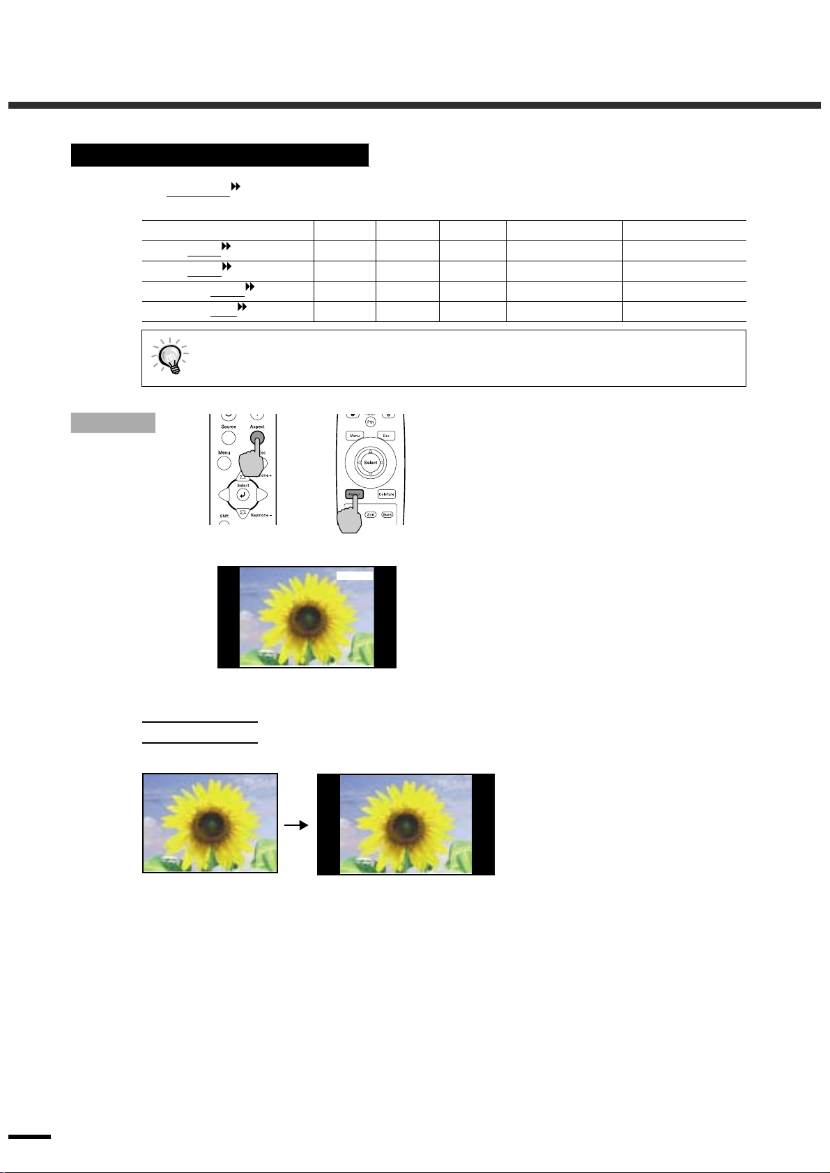
Procedure
Projector
Remote control
Normal
Details of each aspect ratio are as follows.
Normal mode
4:3 image
The aspect ratio changes as shown
below each time the [Aspect] button on
either the remote control or the
projector's control panel is pressed.
Normal → Squeeze → Zoom → Through →
Squeeze Through
The current setting appears on the screen each
time the aspect ratio changes.
The aspect ratio of the images being input
is maintained, and the images are
projected into a 16:9 screen area.
When 4:3 images are being projected,
black bands will appear at the left and
right of the image as shown in the
illustration at left.
14
Page 17
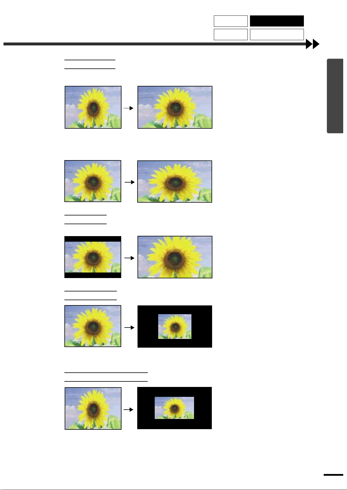
Squeeze mode
Wh
Resized
1280
1280
Focusing the
Screen Image
Selecting the
Color Mode
Selecting the Image
Aspect Ratio
Automatic Adjustment
of Computer Images
en images in squeeze mode
are displayed on a 4:3 TV screen
Images output in 4:3 format
Zoom mode
4:3 image cut at top and bottom
Viewed using the proj ector
Use this setting if the connected video
source has a 16:9 output mode (Squeeze
mode).
If images in squeeze mode are vie wed on a
4:3 TV screen, the images are compressed
horizontally and elongated vertically. If
Squeeze mode is selected on the projector,
the images are projected correctly in their
native wide-screen (16:9) format.
When the projector's squeeze
mode is applied
When images output in 4:3 format are
projected using the projector's squeeze
mode, the images will be extended
horizontally and the image will appear
elongated.
Basic Operations
to 16:9
Images output in 4:3 format are truncate at
top and bottom by a set amount and then
projected in a 16:9 format.
Through mode
Squeeze Through mode
If the input signal resolution is
x 720
dots or less, the images are projected onto
the screen with the input signal resolution
unchanged. Because of this, the size of the
displayed images will change depending
on the input resolution.
The picture quality will be best for
sections of the image that are not resized.
The portions that are not vertically resized
will appear with higher image quality.
If the input signal resolution is
x 720
dots or less, the input signal resolution is
elongated horizontally and the images are
projected at an aspect ratio of 16:9.
Because of this, the size of the displayed
images will change depending on t he input
resolution.
The portions that are not vertically resized
will appear with higher image quality.
15
Page 18
Adjusting the Image Quality
Automatic Adjustment of Computer Images
This function lets you adjust computer images to the optimum settings.
Automatic adjustment involves adjustment of tracking
Focusing the
Screen Image
Selecting the
Color Mode
Selecting the Image
Aspect Ratio
Automatic Adjustment
of Computer Images
display position and synchronization (sync) .
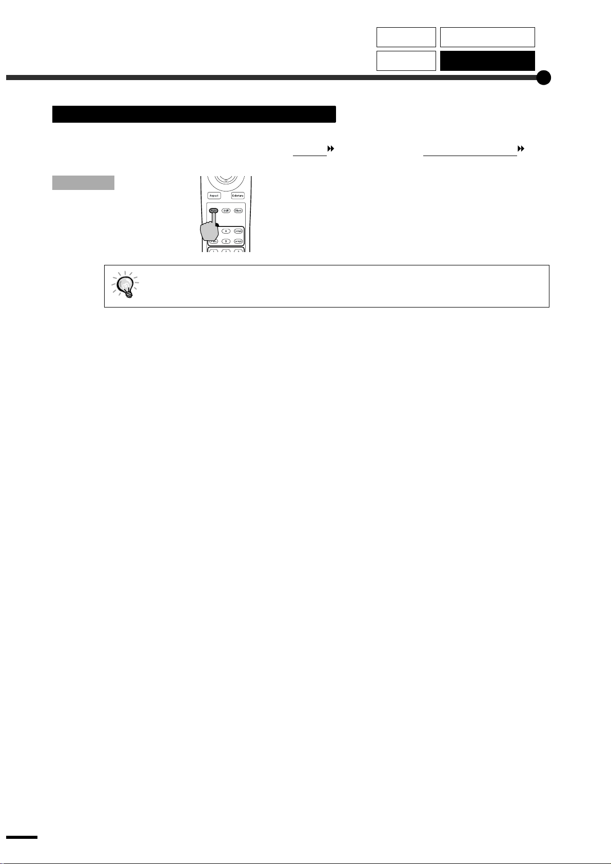
Procedure
While an image is being projected from
the computer, press the [Auto] button
on the remote control.
The screen will appear black while the
adjustment is being made.
Remote control
Automatic adjustment may not work properly with some types of signals which are output by
computers. In such cases, you may need to adjust the tracking and synchronization manually
using projector's environment setting menu. (p.27)
16
Page 19
Advanced Operations
This chapter describes functions fo r enhancing the projection
of images, and how to use the en vironment setting menus.
Functions for Enhancing Projection ..............18
•••• Using the Environment Setting Menus ............................18
• Displaying and Operating Full Menus...................................... .........18
• Displaying and Operating Line Menus..............................................20
•••• Description of Functions.......................................... ..... ....21
• Black Level Adjustment ....................................................................21
• White Level Adjustment ....................................................................21
• Color Adjustment...............................................................................21
•••• Saving and Retrieving Image Qu ality Settin gs
(Memory)..............................................................................22
• Saving Settings ..................................................................................22
• Retrieving Saved Image Quality Settings..........................................23
Using the Menu Functions..............................24
•••• Video Menu........................................................................25
• Video..................................................................................................25
• Computer ...........................................................................................27
•••• Advanced Menu.................................................................29
•••• Setting Menu...................................... ................................30
•••• About Menu .......................................................................31
• Video..................................................................................................31
• Computer ...........................................................................................32
•••• Reset All Menu...................................................................32
1
Page 20
Functions for Enhancing Projection
This section describes the various useful functions that can be used to enhance projection.
Function Summary Reference page
Black level adjustment Adjusts the brightness of dark shades.
White level adjustment Adjusts the brightness of light shades.
Color adjustment Adjusts the hues of light shades to the desired level.
Using the Environment Setting Menus
The functions described here are used to set the adjustment values using the projector’s environment setting
menus.
There are two types of projector’s environment setting menus used:
Full menus : These menus can be used to set all items in the environment setting menus.
••••
Line menus : These menus can be used to change the “Video” settings while viewing the images
••••
being projected. The “Video” menu is the most commonly used of the environment
setting menus. (p.20)
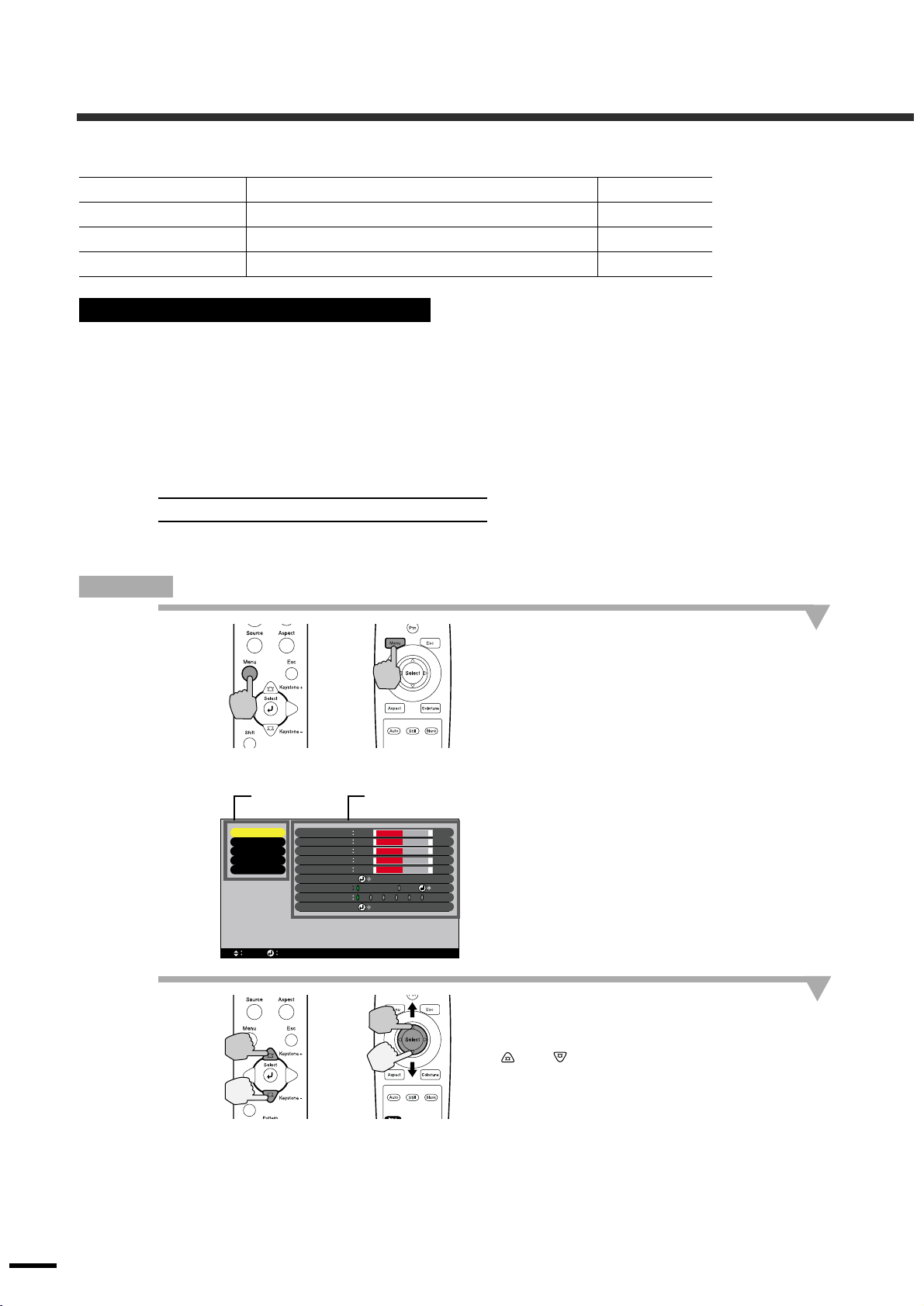
Displaying and Operating Full Menus
Menus can be operated using the projector's control panel and also by using the remote control.
p.21
p.21
p.21
Procedure
1
2
Projector
Main menu
Video
Advanced
Setting
About
Reset All
Select
Enter
Black Level
White Level
Sharpness
Color
Tint
Color Mode
Color Adjustment
Memory
Reset
Remote control
Sub-menu
-
0
-
0
-
0
-
0
-
0
Select
Color Temp. RGB
2 3 4 5 6
1
Execute
+
+
+
+
+
Press the [Menu] button on either the
remote control or the projector's
control panel.
The environment setting menu appears.
Full menus consist of a main menu and submenus. The sub-menu that corresponds to the
currently-selected item in the main menu
(displayed in yellow) appears.
Adjust
Select the items to be changed in the
main menu.
If using the projector's control panel, press the
and buttons.
If using the remote control, tilt the [Select] button
up and down.
18
Projector
Remote control
Page 21
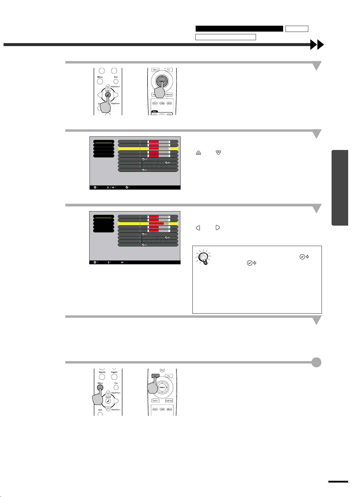
3
Using the Environment Setting Menus Memory
Description of Functions
Select a menu item.
Press the [Select] button on either the projector's
control panel or the remote control to accept a
selection.
The sub-menu corresponding to the selected item
in the main menu appears.
4
5
Projector
Video
Advanced
Setting
About
Reset All
Return
Video
Advanced
Setting
About
Reset All
Return
Select
Select
Black Level
White Level
Sharpness
Color
Tint
Color Mode
Color Adjustment
Memory
Reset
Adjust
Black Level
White Level
Sharpness
Color
Tint
Color Mode
Color Adjustment
Memory
Reset
Adjust
Remote control
-
0
-
0
-
0
-
0
-
0
Select
Color Temp. RGB
2 3 4 5 6
1
Execute
-
0
-
0
-
3
-
0
-
0
Select
Color Temp. RGB
2 3 4 5 6
1
Execute
+
+
+
+
+
+
+
+
+
+
Adjust
Adjust
Select a setting item in the sub-menu.
If using the projector's control panel, press the
and buttons.
If using the remote control, tilt the [Select] button
up and down.
The items appearing in the “Video” menu and
“About” menu will vary depending on the input
signal that is being projected.
Confirm the selection.
If using the projector's control panel, press the
and buttons.
If using the remote control, tilt the [Select] button
to the left and right.
If a setting is executed or a sub-me nu
••••
item continues to another level, "
Enter" or " Select" appears a fter the
item name. In such cases, press the
[Select] button on either the projector's
control panel or the remote control to
select a setting value in the displayed
menu.
Refer to using the menu functions for
••••
details of each setting item. (p.24)
Advanced Operations
6
7
Projector
Set other items in the same way.
Repeat steps 2 to 5 to continue making settings.
T o return to a previous menu level, p ress the [Esc]
button on the projector's control panel or the
remote control.
Exit the menu display.
Press the [Menu] button on either the projector's
control panel or the remote control.
Remote control
19
Page 22

Functions for Enhancing Projection
Displaying and Operating Line Menus
Procedure
1
Press the [Select] button on either the
projector's control panel or the remote
control.
The line menu appears.
2
3
Projector
Black Level
Projector
Remote control
-
0
+
Remote control
Select an item to be set.
If using the projector's control panel, press the
and buttons.
If using the remote control, press the [Select]
button up and down.
The line menu item changes when a button is
pressed.
Select the setting value.
If using the projector's control panel, press the
and buttons.
If using the remote control, press the [Select]
button to the left and right.
20
4
5
Projector
Projector
Remote control
Remote control
Set other items in the same way.
Repeat steps 2 and 3 t o cont i n ue m aki ng s et tin gs .
T o return to a previous menu level, press the [Esc]
button on the projector's control panel or the
remote control.
Exit the menu display.
Press the [Menu] or [Esc] button on either the
projector's control panel or the remote control.
If you do not press a button for 3 seconds
while a line menu is displayed, the line
menu disappears automatically.
Page 23

Description of Functions
This section describes commonly-used functions.
"Black Level" and "White Level" adjustments are the adjustment values that are in effect before the signals
are sampled by the A/D converter, and so they are adju sted to match the input si gnal so that they do n ot cause
distortion. Use "Color Adjustment" to adjust the color and contrast.
Black Level Adjustment
This adjusts the brightness of dark shades. It lets you adjust dark shades without affecting the brightness of
light shades.
Use the "Black Level" item in the "Video" menu to change the setting. (p.25)
Using the Environment Setting Menus Memory
Description of Functions
Brightness
When adjusted
to the + side
If adjusted to the + side, the luminosity of dark scenes
increases and different to nes become clearer , b ut contrast
is reduced.
If adjusted to the - side, the brightness of dark shades is
When adjusted
to the - side
Input signal
reduced and images with greater contrast are obtained,
but differences in dark areas become less distinct.
White Level Adjustment
This adjusts the brightness of light shades. It lets you adjust light sh ades without affecting the brightness of
dark shades.
Use the "White Level" item in the "Video" menu to change the setting. (p.25)
Brightness
When adjusted
to the + side
If adjusted to the + side, the luminosity of light scenes
increases and contrast become clearer, but differences in
light tones are reduced.
If adjusted to the - side, differences in light areas become
When adjusted
to the - side
Input signal
more distinct, but contrast is reduced.
Color Adjustment
Advanced Operations
This adjusts the hues of light shades to the desired hues.
Modes for adjusting the Color Temperature
and for adjusting each individual R/G/B setting are available.
Use the "Color Temp" item in the "Video" menu to change the setting. (p.26, 28)
Color temperature setting
This mode can be used to adjust the color temperature
Flesh tone adjustment
Green
and flesh tones.
The "Color Temp." setting allows lighter colo rs to be
••••
adjusted so that they range from having a red tinge to
having a blue tinge. When the color temperature is
lower, the red content is greater and color tones appear
softer. When the color temperature is higher, the blue
content is greater and color tones appear fresher.
The "Flesh Tone" setting adjusts the green component
••••
of image signals. If adjusted to the - side, the green
component is reduced and colors appear purplish. If
adjusted to the + side, the green component is increased.
Low
(5000 K)
WhiteRed Blue
Purplish
Color
Temperature
High
(10000 K)
Adjust until the desired flesh tones are obtained.
21
Page 24

Functions for Enhancing Projection
Saving and Retrie ving Ima ge Quality Settings (Memory)
Up to a maximum of six adjustment values in the "V ideo" and "Adv anced" menus can be memorize per input
source, and settings for six different sources can be recorded, for a total of 36 po ssible s ettings . You can save
the adjustment values for particular video scenes, and then use the memory button on the remote control to
retrieve these settings at a single touch. (p.26, 28)
The following adjustment values can be stored in memory.
Video menu:
••••
Black Level, White Leve l, Sharpness, Color, Tint, Color Mode, Color Adjustment
Advanced menu:
••••
Progressive, Motion Detect, Noise Reduction, Setup Level
Aspect ratio setting
••••
This is the aspect ratio that is selected using the [Aspect] button on the projector's control panel or the remote
control.
Saving Settings
Procedure
1
2
3
Projector
Video
Advanced
Setting
About
Reset All
Select
Video
Advanced
Setting
About
Reset All
Return
Enter
Select
Black Level
White Level
Sharpness
Color
Tint
Color Mode
Color Adjustment
Memory
Reset
Black Level
White Level
Sharpness
Color
Tint
Color Mode
Color Adjustment
Memory
Reset
Adjust
Remote control
-
0
-
0
-
0
-
0
-
0
Select
Color Temp. RGB
2 3 4 5 6
1
Execute
-
0
-
0
-
0
-
0
-
0
Select
Color Temp. RGB
2 3 4 5 6
1
Execute
+
+
+
+
+
+
+
+
+
+
Adjust
Adjust
Press the [Menu] button on either the
projector's control panel or the remote
control.
The environment setting menu will be displayed,
with the adjustment values appearing as are
currently set.
Select "Memory" from the "Video" submenu.
If using the projector's control panel, press the
and buttons.
If using the remote control, tilt the [Select] button
up and down.
Select the memory num ber (1 - 6) to use
for saving the settings.
If using the projector's control panel, press the
and buttons.
If using the remote control, tilt the [Select] button
to the left and right.
The numbers correspond to memory buttons [1]
to [6] on the remote control.
22
4
Projector
Confirm the memory se tting.
Press the [Select] button on either the projector's
control panel or the remote control.
Remote control
Page 25

Using the Environment Setting Menus Memory
Description of Functions
Retrieving Saved Image Quality Settings
Procedure
Press one of the re mote control
memory buttons [1] to [6]
corresponding to the image quality
settings to be retrieved.
The images being projected will be adjusted
according to the settings that are retrieved.
Remote control
Advanced Operations
23
Page 26

Using the Menu Functions
The environment setting menus can be used to carry out a variety of settings and adjustments. Two types of menu (full
menus and line menus) can be used to make environment settings. This section describes all of the functions that are
available in the environment setting menus using the full menus as examples. The menus have a hierarchical structure,
with a main menu that is divided into sub-menus.
Refer to "Using the Environment Setting Menus" (p.18) for details on using the menus.
Main menu Sub-menu
Video
Advanced
Setting
About
Reset All
Select Enter
Black Level
White Level
Sharpness
Color
Tint
Color Mode
Color Adjustment
Memory
Reset
-
0
-
0
-
0
-
0
-
0
Select
Color Temp. RGB
1
2 3 4 5 6
Execute
+
+
+
+
+
Adjust
24
Page 27

Video Menu
“Video” menu adjustments cannot be carried out when no image signal is being input.
••••
The items appearing in the “Video” menu will vary depending on the input signal that is being projected.
••••
Items in menus other than the menu for the signal currently being input cannot be adjusted.
Video (InputA (YCbCr , YPbPr ), InputB (YCbCr, YPbPr), S-Video, Video)
Video (InputA (YCbCr, YPbPr), InputB (YCbCr, YPbPr), S-Video, Video)
Video menu Setting menu Reset All menu
Advanced menu About menu
Enter
Black Level
White Level
Sharpness
Color
Tint
Color Mode
Color Adjustment
Memory
Reset
-
0
-
0
-
0
-
0
-
0
Select
Color Temp. RGB
2 3 4 5 6
1
Execute
+
+
+
+
+
Adjust
Video
Advanced
Setting
About
Reset All
Select
Main menu Sub-menu Function
Video Black Level This lets you adju st dark shad es withou t a ffe cting the white level setting.
(p.21)
White Level This lets you ad just light s h ades with o ut affecting the black level s etting.
(p.21)
Sharpness Adjusts the image sh arpness. 0
Color Adjusts the color intensity for the images. 0
Tint (A dj ustment is only possi ble for NTSC signal s. )
Adjust th e image tin t.
Color Mode Corrects the vividness of the image color. You can select from five different
quality settings depending on the surroundings.
Dynamic :Ideal for projecting images with greater modulation and
••••
intensity.
Theatre :Ideal for enjoying presentations such as movies which
••••
have large numbers of dark scen es.
Natural :Ideal for enjoying presentations in a natural atmosphere.
••••
PC :Ideal for use in making images as bright as possible when
••••
projectin g co m puter images.
sRGB :Images conform to the sRGB standard.
••••
Default
setting
0
0
0
Dynamic
Advanced Operations
25
Page 28

Using the Menu Functions
Main menu Sub-menu Function
Video Color
Adjustment
Only one of the following settings can be made at any one time. It is not
possible for both settings to be enabled at the same time.
Color Temp.
Color Temp. :Allows lighter colors to be adjusted so that they
••••
setting (p.21)
range from having a red tinge to having a blue
tinge. When the color temperature is lower, the red
content is gre ater and color tones appear softer.
When the color temperature is higher, the blue
content is greater and color tones appear freshe r.
Flesh tone adjustment:The "Flesh Tone" setting adjusts the green
••••
component of image signals. If adjusted to the side, the colors appear purplish. If adjusted to the +
side, the green component is increased. Adjust
until the desired flesh tones are obtained.
RGB setting (Individual adjustment mode)
The Offset , Gain and Gamma can be adjusted separately for each
••••
RGB component. Offset adjusts coloration for darker shades, Gamma
adjusts interm ediate shades, and G ain adjusts brighter shades. The
working of each adjustment is shown below.
Offset adjustment Gamma adjustment
Brightness
When adjusted
to the + side
When adjusted
to the - side
Input signal
Gain adjustment
Brightness
When adjusted
to the + side
The “Color Adjustment” settings correc t the digita l d ata after th e signals
are sampled by the A/D converter.
When the Offset setting is adjusted to the + side, dark colors can be set
freely as desired.
When the Gain setting is adjusted to the - side, light colors can be set
freely as desired.
When the Gain setting is adjusted to the + side, the brightness is
automatically corrected in accordance with the setting value so that the
color does not be come satur ated , so tha t an S- shape d gamma curv e can be
easily created .
Brightness
When adjusted
to the - side
Input signal
Brightness
When adjusted
to the + side
When adjusted
to the - side
Input signal
Default
setting
Color Te mp. :
6700K
Flesh tone
adjustment : 2
RGB :
Offset
R : 0
G : 0
B : 0
Gain
R : 0
G : 0
B : 0
Gamma
R : 2.2
G : 2.2
B : 2.2
26
Input signal
Each RGB component can be adjusted to give the desired level of
coloration to dark, intermediate and light ranges.
Memory This lets you save image adjustment settings and to retrieve them by
pressing the corresponding remote control memory buttons.
The images being projected will be adjusted according to the settings that
are retrieved. (p.22)
The current settings are saved to a particular recording area number when
••••
that number is selected.
The setting values that are saved to memory can be cleared by selecting
••••
"Reset All".
Reset Resets all adjustme nt v al ues f or the “Video” menu functions to their default
settings. However, all se ttings that are stored in memory are retained.
Press the [Sele ct ] on either the projector's control pane l or the remote
••••
control to display the confirmation screen, and select Yes.
Select “Reset All” to return all menu settings to their default settings.
••••
(p.32)
-
-
Page 29

Video menu Setting menu Reset All menu
Advanced menu About menu
Computer (D-RGB/A-RGB DVI-I, InputB (A-RGB))
A(Analog)-RGB D(Digital)-RGB
Enter
Black Level
White Level
Sharpness
Color Mode
Color Adjustment
Memory
Reset
-
0
Auto Manual
-
0
Select
Color Temp. RGB
2 3 4 5 6
1
Execute
Adjust
+
+
Video
Advanced
Setting
About
Reset All
Select Enter
Black Level
White Level
Sharpness
Color Mode
Tracking
Sync.
Color Adjustment
Memory
Reset
-
0
Auto Manual
-
0
Select
0
0
Color Temp RGB
1
2 3 4 5 6
Execute
Adjust
+
+
Adjust
Video
Advanced
Setting
About
Reset All
Select
Main menu Sub-menu Function
Video Black Level This lets you adju st dark shad es withou t a ffe cting the white level setting.
(p.21)
White Level This lets you ad just light s h ades with o ut affecting the black level s etting.
(p.21)
When set to "Auto", the black & white extension fu nction operat es to
emphasize the gradation differences (c ol or densities) when proj ecting
images in dark or light environments, in order to make the images easier to
see.
Sharpness Adjusts the image sh arpness. 0
Color Mode Corrects the vividness of the image color. You can select from five different
quality settings depending on the surroundings.
Dynamic :Ideal for projecting images with greater modulation and
••••
intensity.
Theatre :Ideal for enjoying presentations such as movies which
••••
have large numbers of dark scen es.
Natural :Ideal for enjoying presentations in a natural atmosphere.
••••
PC :Ideal for use in making images as bright as possible when
••••
projectin g co m puter images.
sRGB :Images conform to the sRGB standard.
••••
Tracking
(A-RGB and InputB (A-RGB) only)
Adjusts computer images when vertical stripes appear in the images.
Sync
.
(A-RGB and InputB (A-RGB) only)
Adjusts comput er images when flickering, fuzziness or interference appear
in the images.
Adjust
0
Auto
PC
0
0
Default
setting
Advanced Operations
27
Page 30

Using the Menu Functions
d
Main menu Sub-menu Function
Video Color
Adjustment
Only one of the following settings can be made at any one time. It is not
possible for both settings to be enabled at the same time.
Color Temp.
Color Temp. :Allows lighter colors to be adjusted so that they
••••
setting (p.21)
range from having a red tinge to having a blue
tinge. When the color temperature is lower, the red
content is gre ater and color tones appear softer.
When the color temperature is higher, the blue
content is greater and color tones appear freshe r.
Flesh tone adjustment:The "Flesh Tone" setting adjusts the green
••••
component of image signals. If adjusted to the side, the colors appear purplish. If adjusted to the +
side, the green component is increased. Adjust
until the desired flesh tones are obtained.
RGB setting (Individual adjustment mode)
The Offset , Gain and Gamma can be adjusted separately for each
••••
RGB component. Offset adjusts coloration for darker shades, Gamma
adjusts interm ediate shades, and G ain adjusts brighter shades. The
working of each adjustment is shown below.
Offset adjustment Gamma adjustment
Brightness
When adjusted
to the + side
When adjusted
to the - side
Input signal
Gain adjustment
Brightness
When adjusted
to the + side
The “Color Adjustment” settings correc t the digita l d ata after th e signals
are sampled by the A/D converter.
When the Offset setting is adjusted to the + side, dark colors can be set
freely as desired.
When the Gain setting is adjusted to the - side, light colors can be set
freely as desired.
When the Gain setting is adjusted to the + side, the brightness is
automatically corrected in accordance with the setting value so that the
color does not be come satur ated , so tha t an S- shape d gamma curv e can be
easily created .
Brightness
When adjusted
to the - side
Input signal
Brightness
When adjusted
to the + side
When adjuste
to the - side
Input signal
Default
setting
Color Te mp. :
7500K
Flesh tone
adjustment : 5
RGB :
Offset
R : 0
G : 0
B : 0
Gain
R : 0
G : 0
B : 0
Gamma
R : 2.2
G : 2.2
B : 2.2
28
Input signal
Each RGB component can be adjusted to give the desired level of
coloration to dark, intermediate and light ranges.
Memory This lets you save image adjustment settings and to retrieve them by
pressing the corresponding remote control memory buttons.
The images being projected will be adjusted according to the settings that
are retrieved. (p.22)
The current settings are saved to a particular recording area number when
••••
that number is selected.
The setting values that are saved to memory can be cleared by selecting
••••
"Reset All".
Reset Resets all adjustme nt v al ues f or the “Video” menu functions to their default
settings. However, all se ttings that are stored in memory are retained.
Press the [Sele ct ] on either the projector's control pane l or the remote
••••
control to display the confirmation screen, and select “Yes”.
Select “Reset All” to return all menu settings to their default settings.
••••
(p.32)
-
-
Page 31

Advanced Menu
Video menu Setting menu Reset All menu
Advanced menu About menu
Enter
Progressive
Motion Detect
Noise Reduction
Position
Video Signal
Input A
Input B
Setup Level
Reset
Select [ Film/Auto ]
1 2 3 4 5
OFF NR1 NR2
Adjust
[ Auto ]
Select
Select
Select
0% 7.5%
Execute
Video
Advanced
Setting
About
Reset All
Select
Main menu Sub-menu Function
Advanced Progressive (Can only be adjusted for 525i and 625i image signals)
Changes signal s from Faroudja's inter l aced
mode to progressive (IP)
conversion mode.
OFF :Progressive (IP) convers ion i s carrie d out fo r the scr eens in
••••
each fiel d. It is de sign ed for use wh en v ie wing image s wit h
large amounts of movement. The DCDi function
not operate.
Video :T ur ns off the Film judgment function . The DCDi
••••
function oper ates.
Film/Auto :This setting should normally be used. The projector
••••
automatically determines whether the signal source is a
film source or not. I f the source is a film source, the 3-2
pull-do w n function operates so that film images which
match the original are reproduced. The DCDi function
operates.
Motion
Detect
(Can only be adjusted for 525i and 625i image signals)
Switches the thr ee- di mensional Y/C separation function
operating mode for progressive (IP) conversion depen di ng on whether the
images are moving quickly or slowly.
If a lower setting is used, flickering is reduced and images become sharper
and more distinct. This mode is ideally suited for viewing still images.
If a larger setting is used, images are projected more smoothly with less
jerkiness. This mode is ideally s uited for vie wi ng moving images. Adjust to
suit the type of images being viewed.
Noise
Reduction
(Can only be adjusted for 525i and 625i image signals)
Reduces image interference and m akes the image qualit y softer. Two
modes are available. Use the setting that best suits the images being
viewed. It is recommended that you set th is function to OFF when viewing
images sources such as DVDs which are relatively free from interfer ence.
Position (Adjustment is not possible when D-RGB signals are being input.)
Moves the image display position vertically and horizontally.
Press the [Select] on either the projector's control panel or the remote
••••
control, and make the adjustment using the display position adjustment
screen that appears.
Video Signal (Adjustment is on ly possible when composite or S-Video signals are being
input.)
Sets the video signal format.
Press the [Select] on either the projector's control panel or the remote
••••
control, and select the setting using the menu that appears.
When set to “Auto”, the video signal format is set automatically, but if
••••
projecting signals in N-PAL format, the setting needs to be made
manually.
Input A (Can only be adjusted for 525i and 625i input signals)
Selects the type of signal being input to the Input A port.
and the
does
Default
setting
Film/Auto
3
OFF
Depends on
connection
Auto
YCbCr
Advanced Operations
29
Page 32

Using the Menu Functions
Main menu Sub-menu Function
Advanced Inp ut B Selects the type of sign a l being input to the Input B port. RGB
Setting Menu
Video
Advanced
Setting
About
Reset All
Setup Level (Adjustment is only possible when composite, S-Video, 525i/p or 625i/p
signals are being i nput.)
If using a foreign product that has different black level (setup level)
settings, use this fu nction t o obtain c orrect image s. Check the specif icatio ns
of the connected e qui pment when changing this setting.
Reset Returns the adjustment values in the “Advanced” menu to the default
values.
Press the [Sele ct ] on either the projector's control pane l or the remote
••••
control to display the confirmation screen, and select “Yes”.
Select “Reset All” to return all menu settings to their default settings.
••••
(p.32)
Keystone
No-Signal Msg.
Startup Screen
Blank
Sleep Mode
Projection
Language
Reset
-
0
ON OFF
Black LogoBlue
1min.OFF 10min.5min.
Select
Select
Execute
BlackOFF LogoBlue
+
English
Default
setting
Depends on
countries
-
Select Enter
Main menu Sub-menu Function
Corrects keystone di st or tion in images. (p. 11)
Setting Keystone
••••
When keystone correction is carrie d out, the projected image will become
••••
smaller.
The keystone corr ection setti ngs are memori zed, so that if you chan ge the
••••
position or angle of the projector, you may need to readjust the keystone
correction setting.
If the images become uneven in appearance after keystone correction is
••••
carried out, decrease the “Sharpness” setting.
No-Signal
Msg.
Startup
Sets the screen status when no video signal is being input.
OFF :Screen is completely black.
••••
Black :Screen is completely black and a no signal message appears.
••••
Blue :Screen is completely blue and a no signal message ap pears.
••••
Logo :The user's logo is displaye d and a no signal message appears.
••••
Sets whether the startup screen is displayed or not. ON
Screen
Blank Sets the screen status when the [Blank] button on the remote control is
pressed. The scr een status can be selec te d from "Blue", "Black" or "Logo".
Sleep Mode Use this function if you would like the projector's power to switch off
automatically when image signals stop being input from the connected
equipment.
Setting value range : OFF, 1 minutes, 5 minutes, 10 minutes
When set to “ON”: If the connected equipment has a timer off function,
••••
and this function operates to stop the image signal from being input to the
projector, the projector's lamp also turns off automatically. This can be
used to ensure that the la mp t ur ns o ff even if the viewer falls asleep while
viewing.
When sleep mode has been activated so that the projector is in standby
••••
mode, the lamp will not automatically turn back on again even if a image
signal is input once more. Press the [Power] button on either the remote
control or the projector's control pane l to t urn the power back on.
Default
setting
0
Blue
Black
OFF
30
Page 33

Video menu Setting menu Reset All menu
Advanced menu About menu
Main menu Sub-menu Function
Setting Projection Selects the projection method in accordance with the projector and screen
About Menu
The “About” menu displays the settings for the input source for the images being projected, an d also shows
••••
the lamp status.
The "Lamp" shows times between 0 and 10 hours as 0H. T imes greater than 10 hours appear in u nits of one
••••
hour.
setting-up method .
Front :Projection from the front of the screen
••••
Front/Ceiling :Projection from the front of the screen with the
••••
projector installed to the ceiling (upside down)
Rear :Projection from the rear of the screen
••••
Rear/Ceiling :Proj ection from the rear of the sc reen with t he projecto r
••••
installed to the ceiling (upside down)
Language Sets the language for message, menu and help displays.
Press the [Select] on either the projector's control panel or the remote
••••
control, and select the language from the selectio n menu that appe a rs.
Reset Returns the adjustment values in the “Setting” menu to the default values.
Press the [Select] on either the projector's control panel or the remote
••••
control to display the confirmation screen, and select “Yes”.
Select “Reset All” to return all menu settings to their default settings.
••••
(p.32)
Default
setting
Front
English
-
Video (InputA (YCbCr , YPbPr ), InputB (YCbCr, YPbPr), S-Video, Video)
Video (InputA (YCbCr, YPbPr), InputB (YCbCr, YPbPr), S-Video, Video)
Video
Advanced
Setting
About
Reset All
Select Enter
Main menu Sub-menu Function
About Lamp
Lamp
Reset Lamp Timer
Video Source
Video Signal
0H
Execute
Default
setting
Displays the cumulative lamp operating time.
0H
When the lamp warning period is reached, the display characters appear in red.
Reset Lamp
Timer
Initializes the lamp operating time when the lamp is replaced. When this
command is selected, the cumulative lamp operating time is reset to the
-
initial default va lue.
Video Source D i splays the image so ur ce which is currently bei ng projected. Depends on
connection
Video Signal Displays the video signal format. Auto
Advanced Operations
31
Page 34

Using the Menu Functions
Computer (D-RGB/A-RGB DVI-I, InputB (A-RGB))
Computer
Video menu Setting menu Reset All menu
Advanced menu
About menu
Video
Advanced
Setting
About
Reset All
Select Enter
Lamp
Reset Lamp Timer
Video Source
Input Signal
Frequency
SYNC Polarity
SYNC Mode
Resolution
Refresh Rate
0H
Execute
H kHz
V Hz
H
V
x
Hz
Main menu Sub-menu Function
About Lamp
Displays the cumulative lamp operating time.
When the lamp warning period is reached, the display characters appear in red.
Reset Lamp
Timer
Initializes the lamp operating time when the lamp is replaced. When this
command is selected, the cumulative lamp operating time is reset to the
initial default value .
Video Source D i s plays the image source which is currently being projected. Depends on
Input Signal Displays the input signal settings. Frequency Displays the hor iz ont al scanning frequency. SYNC
Displays the synchronization
polarity. -
Polarity
SYNC Mode Displays the synchronization attributes. Resolution Displays the input resolution. Refresh
Displays the refresh rate. -
Rate
Default
setting
0H
-
connection
Reset All Menu
Video
Advanced
Setting
About
Reset All
Select Enter
Main menu Sub-menu Function
Reset All Execute Resets all items in all environment setting menus to their default settings.
Execute
Press the [Sele ct ] on either the projector's control pane l or the remote
••••
control to display the confirmation screen, and select “Yes”.
To return the settings for items in menus such as the “Video” and
••••
“Advanced” menu to the default settings, select “Reset” in the respective
sub-menus.
The Lamp and Language settings will not return to their def ault settings.
••••
Default
setting
-
32
Page 35

Troubleshooting
This chapter describes troubleshooting procedures for the
projector.
Using the Help..................................................34
When Having Some Trouble............................35
When the Indicators Provide No Help ............37
3
Page 36

Using the Help
If a problem occurs with the projector, the Help function uses on-screen displays to assist you in solving the problem. It
uses a series of menus in a question and answer format. The questions vary depending on the type of video source.
Procedure
1
2
Remote controlProjector
Remote controlProjector
Help Menu
Help for the image
Language selection (Language)
If the suggested solution in Help doesn't solve the problem unplug
the power from the wall outlet and contact your local dealer.
Select Enter
Exit
Press the [Help] button on either the
remote control or the projector's
control panel.
The Help menu will be displayed.
Select a menu item.
If using the projector's control panel, press the
and buttons.
If using the remote control, tilt the [Select] button
up and down.
3
4
Remote controlProjector
Help Menu
No image appears on the screen.
The image is not in focus.
The image is distorted.
The image is not displayed fully on the screen.
(cut off/ too big/ too small/ partial)
The color of the image is abnormal.
The image is too dark.
The image is trapezoi dal.
Enter
Select
Return
Exit
Confirm the selection.
Press the [Select] on either the projector's control
panel or the remote control to confirm the
selection.
The sub-menu appears.
Repeat the operat ion s in steps 2 and 3
to proceed through the menu to more
detailed items.
To return to the previous menu, press the [Esc]
button on either the remote control or the
projector's control panel.
You can exit the Help menu at any time by
pressing the [Help] button on either the
projector's control panel or the remote control.
If the Help function does not provide a
solution to the problem, refer to "When
Having Some Trouble" (p.35) or "When the
Indicators Provide No Help" (p.37).
34
Page 37

When Having Some Trouble
If you are having a problem with the projector, first check the projector's indicators.
The projector is provided with the following three indicators. These indicators alert you to problems with projector
operation.
Operation indicator
Lamp indicator
Temperature indicator
The following tables show what the indicators mean and how to remedy problems that they indicate.
: lit : flashing : off
Indicator status Projector status Problem and remedy
Red
Red
Red
Red
Red
Red
Red
Internal proble m Stop using the projecto r, disconnect the power cord from th e
Red
Fan problem/Sensor
Red
problem
Lamp problem Replace the lamp with a new one.
Lamp operating
error
electrical outlet, and contact your dealer or the nearest add re ss
provided at “International Warranty Conditions” in
Instructions/World-Wide Warranty Terms
package.
Stop using the projector, disconnect the power cord from the
electrical outlet, and contact your dealer or the nearest add re ss
provided at “International Warranty Conditions” in
Instructions/World-Wide Warranty Terms
package.
When replacing the lamp, ch eck that th e lamp and the l amp cov er
are securely installed. If the lamp or lamp cover is not securely
installed, the projector power will not turn on.
This can happen w hen the main power switch at the rear of the
projector was tur ned off before the cool-down
finished t he l ast time t he projec tor w as turn ed o f f, and it w as the n
turned back on agai n before one hour ha d passed.
When turning off the projector, wait 2 minutes. After about 2
minutes, the cooling fan will stop. When the cooling fan stops,
turn off the main power switch and then turn it back on again.
When the main power switch is turned back on, the projector will
return to its previous st ate, so press the [Power] button on either
the remote control or the projector's control panel to turn it back
on. If the lamp ope ra ti ng error happens again when the power is
turned back on, remove th e lamp and check if the lamp is broke n.
If it is not broken, reinstall it. If it is broke n, replace it. Then turn
on the main power switch at the r ear of the projector and pre ss
the [Power] bu tton on either the remote control or the projector's
control panel.
If the indicators still show a problem, stop using the projector,
turn off the main power switch, disconnect the power cord from
the electrical outle t, and contact your deal er or the nearest
address provided at “International Warranty Conditions” in
Safety Instructio ns /World-Wide Warrant y Terms
package.
included in the
included in the
Reference
page
Safety
Safety
p.46
p.46
period had
Troubleshooting
included in the
35
Page 38

When Having Some Trouble
Indicator status Projector status Problem and remedy
Red
High temperature
Red
inside projecto r
(overheating)
The lamp will turn off automatically and projection will stop.
Wait for about 5 minutes with ou t o p er ati ng th e pr oj ec to r. After 5
minutes have elapsed, the projector's cooling fan will stop. When
the cooli ng fa n stops, turn off the main p owe r switch and then
turn it back on again .
If the projector overheat s, check the following two p o i nt s.
Is the setting-up location well ventilated?
••••
Check that the air inl et and air outlet are clea r, and that the
projector is not positioned against a wall.
Is the air filter blocke d with dust ?
••••
If the air filter is dirty, it should be cleaned.
When the main power switch is turned back on, the projector will
return to its previous state, so press the [Power] button on either the
remote control or the projector's control panel to turn it back on. If
the projector continues to overheat even after the above points have
been checked, or if the indicators show a problem when the power
is turned back on, stop using the projector, turn off the main power
switch, disconnect the power cord from the electrical outlet, and
contact your dealer or the nearest address provided at
Orange
High-speed cooli ng
in progress
“International Warranty Conditions” in
Wide Warranty Terms
included in the package.
(This is not an abnormality, but if the temperature rises too high
again, projection will stop automatically.)
Set the projector up in a place which is well-ventilated , and so
••••
Safety Instructions/World-
that the air inlet and exhaust vents are clear.
Clean the air filter.
••••
* The appearance of the indicator at this time will va ry
depending on the status of the pro je ct or.
Orange
Lamp will soon need
to be replaced.
(No abnormality)
Have a new replacement lamp ready.
The lamp service life can become shorter tha n normal a s a result
of the usage conditions, and so the lamp should be replaced as
soon as possible.
* The appearance of the indicator at this time will va ry
depending on the status of the pro je ct or.
Orange
Standby condition (No abnormality)
Projection start s w hen the [Power] button on either the remote
control or the projector's control panel is pressed.
Reference
page
Setup Guide
p.44
Setup Guide
p.44
p.45
p.6
36
Green
Green
Orange
Warm-up in progress (No abnormality)
p.7
Wait for a short while. The indicator will stop flashing and light
with a green col or.
Projecting in
(No abnormality) p.7
progress
Cool-down in
progress
(No abnormality)
Wait for a short while.
••••
The cool-down
(lamp cooling operation) period lasts for
p.8
about 2 minutes. The actual time will v ary depend ing on facto rs
such as the ambien t air temperature.
The [Power] button on either the remote control or the
••••
projector's control panel will not operate during the cool-down
period. When cool-down is complete, the indicator will stop
flashing and light orange. You can then use the [Power] button.
If the main power swi tch at the rear of the pr oj ector is turned
••••
off before cool-down is complete, wait for the lamp to cool
down (normally about one hour is required) before turnin g t h e
power back on again.
If the projector is no t op erat ing pro perly e ven though the indicators are all sho w ing no rmal, ref er
••••
to "When the Indicators Provide No Help" on the following page.
If an indicator is showing a status which does not appear in the previous tables, contact your
••••
dealer or the nearest address provided at “International Warranty Conditions” in
Instructions/W orld-Wi de Warranty Terms
included in the packa ge.
Safety
Page 39

When the Indicators Provide No Help
If any of the following problems occur and the indicators do not offer a solution, refer to the pages given for
each problem.
No images appear p.37, p.38 Images appear dark p.41
Poor image quality p.39 Images appear green p.41
Only part of the image is displayed (Large/small) p.40 The remote control does not work p.41
The image colors are not right p.40 The power does not turn off p.42
Condition
No images appear (Nothing at all appears)
Probable cause Remedy
Is the lens cover still attached?
Is the power cord disconnected?
Is the main power switch turned off?
Was the power turned off and then straight
back on again?
While the indicator i s flashing orange (during cooldown ), the [Power] button on eiher the remote
control or the projector's control pan el will not oper ate .
Have you pressed the [Power] button on
either the remote control or the projector's
control panel?
Is sleep mode active?
When sleep mode has been set to “ON”, the lamp turns
off automatically if no operations are carried out for a
set period of time while no video signal is being input.
The indicator lights orange at this time.
Is blank mode active?
Is the projected image completely black?
Some input images, such as screen savers, may be
completely black.
Is a image signal being input?
If "No-Signal Msg." in the “Setting” menu has been set
to "OFF", no messages will be displayed.
Try resetting all of the current settings.
Remove the lens cover. (p.6)
Check the power cable connectio n at the po wer inlet of
the projector and at the wall outlet. (p.6 )
Turn on the main power switch at the rear of the
projector. (p.6)
W ait un til cool-do wn h as fini shed. You can then use the
[Power] butto n on eithe r the remot e cont rol or the
projector's contr ol panel. (p.8)
Press the [Power] b utton on eit her the remo te control or
the projector's control panel. (p.7)
Turn the projector power back on. To cancel the sleep
mode setting, set "Sleep Mode" in the “Setting” menu
to "OFF".
“Setting” - “Sleep Mode” (p.30)
Press the [Blank] button on the remote control to cancel
the blank function.
“Setting” - “Blank” (p.30)
Cancel the screen saver, or re-check the images being
input.
Change the "No-Signal Msg." setting to "Black" or
"Blue" for messages to be displayed.
“Setting” - “
If a message is displa yed, refer to the item indicated.
“Reset All” (p.32)
No-Signal Msg.”
(p.30)
Troubleshooting
37
Page 40

When the Indicators Provide No Help
Probable cause Remedy
Does the input signal setting match the
connected source?
Has the correct image input port been
selected?
Is the power for the computer or video source
turned on?
Check the mode which corresponds to the
frequency of the image signals being output
from the computer.
If a laptop computer or a computer with a
LCD screen has been connected to the
projector, it is necessary to output the image
signals to the projector rather than to the
screen.
Condition
No images appear (Messages do appear)
“Not Suppored.” message appears on the screen.
“No-Signal.”message appear on the screen.
Use the “Video Signal”, “Input A” or “Input B”
commands in the “Advanced” menu to select the signal
format that matches the connected source.
“Advanced” - “Video Signal”, “Input A”, “Input B”
(p.29)
Press the [Source] button on the projector's control
panel (or the [D-RGB], [A], [B], [Video] or [S-V id eo]
button on the remote control) to ch a nge the image
source. (p.7)
Turn on the power. (p.7)
Refer to the documentation provi ded with your
computer for details on changing the resolution and
frequency of the ima g e signals being outp ut fr om the
computer. (p.50)
Normally image signals are output to only the
computer's LCD screen, so you need to change the
output to an external destination. For some computer
models, when the image signals are output externally,
they no longer appear on the LCD screen. For details,
refer to the section of the documentation provided with
your computer under a head in g such as "External
output", "Connecting an external monitor" or similar.
(p.7)
38
Page 41

Condition
Poor image quality
••••
••••
••••
••••
••••
Probable cause Remedy
Has the focus been adjusted correctly?
Has the front adjustable foot been adjusted
so that the projection angle is too big?
If the projection angle is too big, the image will be out
of focus vertically.
Is the projector at the correct distance?
Is the projector beam perpendicular to the
screen?
Is the lens dirty?
Has condensation formed on the lens?
If the projector is suddenly taken from a cold
environment to a warm environment, condensation may
form on the lens, and this may ca use the images to
appear fuzzy.
Does the input signal setting match the
connected source?
Are the cables connected correctly?
Is an extension cable being used?
If an extension cable is used, electric al interference
may increase.
Have the synchronization , tracking and
display position been adjusted correctly?
(When connected to a computer)
Has the correct resolution been selected?
(When connected to a computer)
The image is fuzzy
Part of the image is out of focus
The whole image is out of focus
The image is distorted
The image contains interference
Adjust the focus. (p.13)
Adjust the projection angle. (p.10)
The recommended distance from the projector to the
screen is within 0.9 - 13 m (2.9 - 42.6 ft). Set up the
projector so that the projection distance is within this
Setup Guide
range. (
Adjust the projection angle so that the projector beam
is perpendicular to the screen. (p.10)
Clean the lens. (p.44)
Turn off the power and wait for the condensation to
disappear.
Use the “Video Signal”, “Input A” or “Input B”
commands in the “Advanced” menu to select the signal
format that matches the connected source.
“Advanced” - “Video Signal”, “Input A”, “Input B”
(p.29)
Check that all cables that are required for projection are
connected correctly. (
Use the accessory cables provided, or co nnect a signal
amplifier and see if this helps.
Press the [Auto] button on either the remote control or
the projector's control panel to adjust these settings.
You can also use the environment setting menus to
make the adjustment. (p.16, “Video” - “Tracking” ,
“Sync.” p.27)
Set the computer so that the signals t hat are output are
compatible with this projector. Refer to the
documentation pro vided with your compu ter for deta ils
on changing the settings. (p.50)
)
Setup Guide
)
Troubleshooting
39
Page 42

When the Indicators Provide No Help
Probable cause Remedy
The display mode (aspect ratio ) setting
may not be selected correctly.
Has the "Position" setting been adjusted
correctly?
Has the correct resolution been selected?
Change the resolution for the laptop
computer or computer with a LCD screen.
Has the computer been set for dual display?
Condition
Image is too large (Only part of the image is displ ayed)
••••
Image is too small
••••
Press the [Aspect] button on either the remote control
or the projector's co ntrol panel. (p.14)
Use the “Position” command in the “Advanced” menu
to adjust. (p.29)
Set the computer so that the signals that are output are
compatible with this projector. Refer to the
documentation pro vided with your comput er for details
on changing the settings. (p.50)
Change the resolution so that the image is displayed in
the whole of the projection area, or set the image signal
to external output only. (p.7)
If dual display has been activated in the “Display
Properties” of the computer's “Control Panel”, the
projector will only project about half of the image on
the computer screen. To display the whole of the image
on the computer screen, turn off the dual display
setting. Refe r to the video driver manual for the
computer's monitor for further details.
Condition
The image colors are not right
Probable cause Remedy
Are the cables connected correctly?
Has the image contrast been adjusted
correctly?
Has the color been adjusted correctly?
Have the color intensity and tint been
adjusted correctly?
(The colors may not exactly match the colors in the
image on the computer screen or LCD screen, but this
is normal and is not t he sign of a problem.)
Is the lamp due for replacement?
If the indicator is flashing orange, it means that the
lamp will soon be due for replacem ent. Whe n th e lamp
is nearly due for replacement, the image will become
darker and the tint will become poorer.
Does the input signal setting match the
connected source?
Check that all cables that are required for projection are
connected correctly. (
Use the “White Level” command in the “Video” menu
to adjust the contrast.
“Video” - “White Level” (p.25, 27)
Use the “Color Adjustment” command in the “Video”
menu to adjust the contrast.
“Video” - “Color Adjustment” (p.26, 28)
Use the “Video” menu to adjust the “Color” and “Tint”
settings
“Video” - “Color”, “Tint” (p.25)
Replace the lamp with a new one. (p.46, 47)
Use the “Video Signal”, “Input A” or “Input B”
commands in the “Advanced” menu to select the signal
format that matches the connected source.
“Advanced” - “Video Signal”, “Input A”, “Input B” (p.29)
Setup Guide
)
40
Page 43

Condition
Images appear dark
Probable cause Remedy
Is the lamp due for replacement?
If the indicator is flashing orange, it means that the
lamp will soon be due for rep la cem ent. Whe n th e l amp
is nearly due for replacement, the image will become
darker and the tint will become poorer.
Condition
Images appear green
Probable cause Remedy
Do the settings for component video input
signals match the signals from the connected
device?
If the YCbCr or YPbPr settings are incorrect, the
images may appear greenish.
Replace the lamp with a new one. (p.46, 47)
Use the “Input A” or “Input B” commands in the
“Advanced” menu to select the signal format that
matches the connected source.
“Advanced” - “Input A” , “Input B” (p.29)
Probable cause Remedy
Is the remote control being pointed at the
right angle?
Is the remote control too far from the
projector?
Is direct sunlight or strong light from
fluorescent lamps shining onto the remote
control light-receiving area?
Are there batteries in the remote control?
Are the batteries dead?
Have the batteries been inser te d corr ec tly?
Condition
The remote control does not work
The operating angle for the remot e control is
approximately 30° horizontally and approximately 30°
vertically. Use the remote control within these ranges.
Setup Guide
(
The operating distance for the remote co ntrol is
approximately 10 m (30 ft.). Use the remot e control
within this distance. (
A void using projector in places where the remote
control light-receiving area is exposed to strong light.
Insert batteries into the remote control. (
Replace the batteries with new ones. (
Insert the batteries so that they face in the correct
direction. (
)
Setup Guide
Setup Guide
)
)
Setup Guide
Setup Guide
Troubleshooting
)
)
41
Page 44

When the Indicators Provide No Help
Probable cause Remedy
Is the indicator still orange?
This projector is designed so th at the indicator
remains lit even when after the power has been turned
off.
Is the fan still operating?
After the [Power] b utton o n either the rem ote control or
the projector's control panel is pressed to turn off the
power, the cool-down
period starts.
Condition
The power does not turn off (after the [Power] button is
pressed)
When the main power switch at the rear of the projector
is turned off, the indicator switches off.
After the cool-down period is compl ete, the
indicator changes to a steady orange, and you can then
turn off the main power switch at the rear of the
projector.
* The cool-down period lasts for about 2 minutes. The
actual time will vary depending on factors such as
the ambient ai r temperature .
42
Page 45

Appendices
This chapter provides information on maintenance
procedures to ensure the best level of performance for the
projector for a long time.
Maintenance .....................................................44
•••• Cleaning..............................................................................44
• Cleaning the Projector Case...............................................................44
• Cleaning the Lens ................................... ...........................................44
• Cleaning the Air Filter.......................................................................44
•••• Replacing Consumables....................................................45
• Lamp Replacement Period.................................................................45
• Replacing the Lamp...........................................................................46
• Resetting the Lamp Operating Time.................................. ................47
• Replacing the Air Filter .....................................................................48
Optional Accessories......................................49
List of Supported Signal Resolutions............50
•••• Component Video Input....................................................50
•••• Composite Video/S-Video Input.......................................50
•••• RGB Input..........................................................................51
Specifications...................................................52
Appearance ......................................................54
Part Names and Functions..............................55
•••• Front/Top............................................................................55
•••• Control Panel...................................................... ...............56
•••• Rear.....................................................................................57
•••• Base.....................................................................................57
•••• Remote Control......................................................... .........58
Glossary............................................................59
Index..................................................................61
4
Page 46

Maintenance
This section describes maintenance tasks such as cleaning the projector and replacing consumable parts.
Cleaning
You should clean the projector if it becomes dirty or if the quality of projected images starts to deteriorate.
Be sure to read the separate
details on safe handling of the projector during cleaning.
Safety Instructions/World-Wide Warranty Terms
for
Cleaning the Projector Case
Clean the projector case by wiping it gently with a soft cloth.
If the projector is particularly dirty, moisten the cloth with water containing a small amount of neutral
detergent, and then firmly wring the cloth dry before using it to wipe the projector case. Then wipe the case
again with a soft, dry cloth.
Do not use volatile substances such as wax, alcohol or thinner to clean the projector
case. These can cause the case to warp and make the coating finish peel off.
Cleaning the Lens
Use a commercially-available air blower, or use a lens cleaning paper to gently wipe the lens.
Do not rub the lens with harsh materials or subject the lens to shocks, as it can
easily become damaged.
Cleaning the Air Filter
If the air filter becomes clogged with dust, it can cause overheating and damage the projector.
Stand up the projector in order to prevent dust getting inside the projector, and then use a vacuum cleaner to
clean away the dust from the air fil ter.
If the air filter is difficul t to clean or if it is brok en,
••••
it should be replaced. Contact your dealer for a
spare air filter .
Replacement lamps are provided with a spare
••••
air filter. The air filter should also be replaced
when the lamp is replaced.
44
Page 47

Replacing Consumables
This section describes how to replace the lamp and the air filter.
Lamp Replacement Period
It is time to replace the lamp when:
The message "Lamp Replace" appears on the screen when projection starts.
••••
A message will be displayed.
The indicator flashes orange or lights red.
••••
Cleaning
Replacing Consumables
The message appears for 30 seconds, and disappear s again
after 30 seconds have passed.
Lamp indicator flashes orange or lights red.
The projected image gets darker or starts to deteriorate.
••••
In order to maintain the brightness and quality of the projected images, replace the lamp as
••••
soon as possible after the warning message appears.
The replacement warning message is set to appear after 2900 hours of lamp use in order to
••••
maintain the brightne ss and qu ality of th e proje cted images . If y ou c ontinue to use the lamp afte r
this period, the possibility of the lamp breaking becomes greater. When the lamp replacement
message appears, replace the lamp with a new one as soon as possible, even if it is still
working.
The warning message appears after 2900 hours of use, but the actual life of each individual
••••
lamp will vary depending on the characteristics of the lamp and on the way it has been used.
Some lamps may stop operating before 2900 hours of use, so you should always have a spare
lamp ready in case.
When the lamp replacement warning message appears, the user's logo will not appear even if
••••
the “Start-up screen” setting is “ON”.
Contact your dealer for a spare lamp.
••••
Appendices
45
Page 48

Maintenance
Procedure
Replacing the Lamp
If the lamp stops working and needs to be replaced, there is the danger that the lamp may
••••
break when handled.
If replacing the lamp of a projector which has been installed to the ceiling, you should
remove the projector from the ceiling before replacing the lamp. If the projector cannot be
removed from the ceiling, you should always assume that the lamp is broken and handle it
with extreme care during removal. Furthermore, you should stand to the side of the
projector, not underneath it.
Wait until the lam p has cool ed do wn sufficiently bef ore openi ng the lamp cover. After the
••••
cool-down
be cool enough.
period has finished, it tak e s appr oximately a further 30 minutes f or the l amp to
1
2
3
Turn off the main power switch at the
rear of the projector. (p.8)
Wait until the lamp has cooled down,
and then remove the lamp cover.
After the cool-down period has finished, it takes
approximately a further 30 minutes for the lamp
to be cool enough.
Use the screwdriver that is provided with the
replacement lamp to slide the lamp cov er op ening
switch so that the lamp cover lifts up. Hold the
raised section of the lamp cover and then slide it
forward to remove it from the projector.
Loosen the two lamp fixing scr ews.
Use the screwdriver that is supplied with the
replacement lamp to loosen the two lamp fixing
screws that are securing the lamp to the projector.
46
4
5
Take out the lamp.
Hold the lamp by the two recesses on the side to
lift it up and out from the projector.
Install the new lamp.
Hold the lamp so that it faces the correct way to
fit into the projector, and then insert the lamp
until it clicks into place and tighten the two fixing
screws.
Page 49

Cleaning
Replacing Consumables
6
Install the lamp securely. If the lamp cover is removed, the lamp turns off automatically as a
••••
safety precaution. Moreover, the lamp will not turn on if the lamp or the lamp cover is not
installed correctly.
Replacement lamps are provided with a spare air filter. The air filter should also be replaced
••••
when the lamp is replaced.
Dispose of used lamps properly in accordance with your local regulations.
••••
Install the lamp cover.
Insert the two cover tabs into the projector, and
then press the other side of the lamp cover until it
clicks into place.
Resetting the Lamp Operating Time
The projector has a built-in counter which keeps track of the lamp operating time. When the cumulative
operating time reaches a certain point, it causes the replacement w arning message to b e displayed. Therefore,
the counter needs to be reset after the lamp has been replaced with a new one. You can do this using the
projector menu.
Do not reset the la mp op er ating time e xc ept a fter the lamp has b een re place d, othe rwis e the lamp
replacement period will not be in dicated correctly.
Procedure
1
2
3
Projector
Lamp
Reset Lamp Timer
Video Source
Video Signal
Remote control
2900H
Execute
Reset Lamp Timer
Execute?
Yes No
Press the [Menu] button on either the
remote control or the projector's
control panel.
The environmen t setti ng menu will be displa yed .
Select “Reset Lamp Timer” from the
“About” menu.
Press the [Select] on either the projector's control
panel or the remote control.
Reset the lamp operating tim e.
Select “Yes”, and then press the [Select] on either
the projector's control panel or the remote
control.
Appendices
47
Page 50

Maintenance
Procedure
Replacing the Air Filter
1
2
Turn off the power switch at the rear of
the projector, and then disconnect the
power cord. (p.8)
Put your finger into the recess in the air
filter hook, and lift up the ai r filter to
remove it.
In order to prevent any dust on th e air filter from
getting into the projector, be sure to stand up the
projector so that the handle is at the top.
3
Install the new air filter.
First insert the tabs, and then press down on the
opposite side until it clicks into place.
Dispose of used air filters properly in accordance with your local regulations.
48
Page 51

Optional Accessories
The following optional accessories are available for purchase if required. This list of optional accessories is
current as of February 2002. Details of accessories are subject to change without notice.
Spare lamp ELPLP17
Use as a replaceme nt for spent lamps.
Portable screen (50 inch) ELPSC06
A compact screen w h i ch can be carried easi ly.
60 inch screen ELPSC07
80 inch screen ELPSC08
Component video cable ELPKC19
(9.8 ft (3 m) - for mini D-Sub 15-pin/RCA x 3)
Use to connect a component video source.
Computer cable ELPKC02
(1.8 m (6 ft) - for mini D-Sub 15-pin/mini D-Sub
15-pin)
Use to connect the projector to a computer when you would
like to use UXGA
display resolution.
Computer cable ELPKC09
(3 m (9.8 ft) - for mini D-Sub 15-pin/mini D-Sub
15-pin)
Computer cable ELPKC10
(20 m (65.6 ft) - for mini D-Sub 15-pin/mini DSub 15-pin)
Use this extension cable if the accessory computer cable is
too short.
Digital video cable ELPKC20
(3 m (9.8 ft) - DVI-D male-male)
DVI cable for connec t ing the projector to a com puter
with a digital RGB output interface.
Digital video cable ELPKC21
(3 m (9.8 ft) - for DVI-D/DFP 20-pin)
DFP cabl e for connecting th e projector to a computer
with a digital RGB output interface.
DVI analog cable ELPKC25
(3 m (9.8 ft) - for DVI-I/mini D-Sub 15-pin)
Use to connect the projector to connect two computers with
analog RGB output to th e pr oj ector.
Ceiling mount
Use when instal li ng the projector to a ceiling.
Ceiling plate
Pipe 370 (370 mm (14.57 inches)/silver)
*
*
ELPMB07
ELPFC03
*
ELPFP04
Pipe 570 (570 mm (22.44 inches)/silver)
*
ELPFP05
Pipe 770 (770 mm (30.31 inches)/silver)
*
ELPFP06
Use when instal ling the projector to a high ceiling or a
ceiling with veneer panels.
Image presentation camera ELPDC02
ELPDC03
Use when project ing books, OHP films and sl ides.
Hard travel case ELPKS26
Soft carrying case ELPKS27
Use this case if you n eed to carry the proje ct or by hand.
*A s pecial method of installation is required in order to suspend the projector from the ceiling. Please
contact the place of purchase if you would like to use this installation method.
Appendices
49
Page 52

List of Supported Signal Resolutions
Component Video Input
Aspect
Signal Resolution
SDTV
(525i, 60Hz)
SDTV
(625i, 50Hz)
SDTV (525p) 640 × 480
SDTV (625p) 768 × 576
HDTV
(750p) 16:9
HDTV(1125p)16:9 1920 × 1080 1280 × 72 0
640 × 480
640 × 360 (When zoomed)
768 × 576
768 × 432 (When zoomed)
640 × 360 (When zoomed)
768 × 432 (When zoomed)
1280 × 720 1280 × 720
Normal
(Default)
960 × 720
(4:3 aspect)
960 × 720
(4:3 aspect)
960 × 720
(4:3 aspect)
960 × 720
(4:3 aspect)
(16:9 aspect)
(16:9 aspect)
Squeeze Zoom Through
1280 × 720
(16:9 aspect)
1280 × 720
(16:9 aspect)
1280 × 720
(16:9 aspect)
1280 × 720
(16:9 aspect)
––1178 × 664
––886 × 498
1280 × 720
(16:9 aspect)
1280 × 720
(16:9 aspect)
1280 × 720
(16:9 aspect)
1280 × 720
(16:9 aspect)
590 × 442
(4:3 aspect)
700 × 525
(4:3 aspect)
590 × 442
(4:3 aspect)
700 × 525
(4:3 aspect)
(16:9 aspect)
(16:9 aspect)
Units: dots
Squeeze
Through
786 × 442
(16:9 aspect)
934 × 525
(16:9 aspect)
786 × 442
(16:9 aspect)
934 × 525
(16:9 aspect)
–
–
Composite Video/S-Video Input
Signal Resolution
TV (NTSC) 640 × 480
640 × 360 (When zoomed)
TV
(PAL, SECAM)
768 × 576
768 × 432 (When zoomed)
Normal
(Default)
960 × 720
(4:3 aspect)
960 × 720
(4:3 aspect)
Aspect
Squeeze Zoom Through
1280 × 720
(16:9 aspect)
1280 × 720
(16:9 aspect)
1280 × 720
(16:9 aspect)
1280 × 720
(16:9 aspect)
590 × 442
(4:3 aspect)
700 × 525
(4:3 aspect)
Units: dots
Squeeze
Through
786 × 442
(16:9 aspect)
934 × 525
(16:9 aspect)
50
Page 53

RGB Input
VGA
72/75/85, iMac*1
56/60*/72/75/85/, iMac*1
43i/60*/70/75/85, iMac*1
Component Video Input RGB Input
Composite Video/S-Video Input
Units: dots
Aspect
Signal Resolution
PC98 640 × 400 1152 × 720 – 640 × 400
EGA 640 × 350 1280 × 700 – 640 × 350
60 *, SDTV
(525p)
VESA
SVGA
XGA
1024 × 576 (When zoomed)
1152 × 864
70/75/85
QVGA
60*/75/85
SXGA
43i/60*/75/85
MAC13” 640 × 480 960 × 720 – 640 × 480
MAC16” 832 × 624 960 × 720 – 832 × 624
MAC19” 1024 × 768 960 × 720 ––
MAC21” 1152 × 870 954 × 720 ––
SDTV
(525i, 60Hz)
(625i, 50Hz)
SDTV (625p) 768 × 576
HDTV
(1125i, 1125p)
SDTV
(750p)
HDTV
1152 × 648 (When zoomed)
1280 × 720 (When zoomed)
1280 × 720 (When zoomed)
640 × 480
640 × 360 (When zoomed)
640 × 480
640 × 360 (When zoomed)
800 × 600
800 × 450 (When zoomed)
1024 × 768
1152 × 864
1280 × 960
1280 × 1024
640 × 480
640 × 360 (When zoomed)
768 × 576
768 × 432 (When zoomed)
768 × 432 (When zoomed)
1280 × 720 1280 × 720 – 1178 × 66 4
1920 × 1080 1280 × 720 – 886 × 498
Normal
(Default)
960 × 720 1280 × 720 640 × 480
960 × 720 1280 × 720 640 × 480
960 × 720 1280 × 720 800 × 600
960 × 720 1280 × 720 –
960 × 720 1280 × 720 –
960 × 720 1280 × 720 –
900 × 720 1280 × 720 –
960 × 720 1280 × 720 590 × 442
960 × 720 1280 × 720 700 × 525
960 × 720 1280 × 720 700 × 525
Zoom Through
* indicates resolutions that are compatible with both analog and digital formats.
*1 This connection is not possible for models which are not equipped with a VGA output port.
Appendices
51
Page 54

Specifications
Product name
Dimensions
Panel size
Display method
Drive method
Resolution
Focus adjustment
Zoom adjustment
Lamp (light source)
Power supply
Operating
temperature
Storage
temperature
Home Theatre Projector EMP-TW100
348 (W) x 104 (H) x 274 (D) mm
(13.7 (W) x 4.09 (H) x 10.79 (D) inches) (not including p rotruding parts)
0.87 inches
Polysilicon TFT active matrix
Full-line 12-phase block sequential writing
921,600 pixels (1280 (W) x 720 (H) dots) x 3
Manual
Manual (approx. 1:1.35)
UHE lamp, 150 W, Model No.: ELPLP17
100 – 120 VAC, 2.7A
200
240 VAC, 1.3A
–
50/60 Hz
+5°C – +35°C (41°F - 95°F) (No condensation)
-10°C – +60°C (14°F - 140°F) (No condensation)
Weight
Connectors
Approx. 4.2 kg (9.3 lbs)
A-RGB/D-RGB DVI-I 1 DVI-I
InputA 1 3RCA pin jack
InputB 1 Mini D-Sub 15-pin (female)
Video 1 RCA pin jack
S-Video 1 Mini DIN 4-pin
RS-232C 1 D-Sub 9-pin (male)
Trigger 1 3.5 mm mini jack
52
Page 55

Safety
USA
UL1950 3rd Edition
Canada
CSA C22.2 No.950 -95 (cUL )
European Community
The Low Voltage Directive (73/23/EEC)
IEC60950 2nd Edition, +Amd.1, +Amd.2, +Amd.3, +Amd.4
EMC
USA
FCC 47CFR Part15B Class B (DoC)
Canada
ICES-003 Class B
European Community
The EMC Directive (89/336/EEC)
EN55022, 1998 Class B
EN55024, 1998
IEC61000-4-2, IEC61000-4-3, IEC61000-4-4, IEC61000-4-5,
IEC61000-4-6, IEC61000-4-8, IEC61000-4-11,
IEC61000-3-2, IEC61000-3-3
Australia/New Zealand
AS/NZS 3548:1995, A1:1997, A2:1997 Class B
CISPR Pub.22:1993, A1:1995, A2:1996, Class B
Appendices
53
Page 56

Appearance
104
(4.09)
274
(10.79)
114
(4.49)
54
348
(13.7)
Units: mm (inch)
Page 57

Part Names and Functions
Front/Top
Front/Top Rear Remote control
Control panel Base
Zoom ring (p.10)
Adjusts the image size.
Focus ring (p.13)
Adjusts the image focus.
Lamp cover (p.46)
Open this cover when replacing
the lamp unit inside the projector.
Lamp cover opening switch
(p.46)
Slide this switch to unlock the lamp
cover when removing it.
Security lock ()
(p.60)
Air exhaust vent
Temperature indicator
(p.35)
Indicates abnormalities in the
internal projector temperature.
Lamp indicator (p.35)
Indicates a problem with the
projection lamp or that the lamp
needs to be re placed.
Operation indicator
(p.35)
Flashes or lights to indicate the
operating status of the projector.
Control panel (p.56)
Remote control lightreceiving area
(
Setup Guide
Receives signals from the
remote control.
)
Front adjustable foot
(p.10)
Extend and retract to adjust
the projection angle.
Lens cover
Attach when not using the
projector to prevent the lens from
becoming dirty or damaged.
Handle
Hold this handle when
lifting and transporting the
projector.
Foot adjust button (p.10)
Press this button while lifting up
the projector in order to make
fine adjustments to the adjustable
foot or to retract it.
Appendices
55
Page 58

Part Names and Functions
Control Panel
[Power] button (p.7)
Press to turn the projector
power on and off.
[Source] button (p.7)
Switches the input source
between InputA → InputB
S-Video → Video →
→
D-RGB → A-RGB each
time the button is pressed.
[Menu] button (p.18)
The environment setting
menus turn on and off each
time the [Menu] button is
pressed.
[Keystone] buttons
(p.11)
Press to select an item in an
environment set ting menu or
help menu.
Press and hold the [Shift]
button while pressing these
buttons to correct keystone
distortion of images.
[Shift] button (p.11)
This button does not
function by itself. Press and
hold this button while
pressing the [Keystone +]
button or the [Keyst one -]
button to correct keystone
distortion of images.
[Colortune] button
(p.13)
Switches the color mode
between Dynamic →Theatre
Natural → PC → sRGB
→
each time the button is
pressed.
[Help] button (p.34)
Displays the online help menu to
assist you if you have a problem
[Aspect] button (p.14)
Selects the aspect ratio for
projected images from one of
five settings.
The aspect ratio switches
between Normal → Squeeze →
Zoom → Through →
Squeeze Through each time the
button is pressed.
[Esc] button (p.19, 34)
Pressing [Esc] while viewing an
environment s etting menu or the
online help displays the previous
screen or menu.
[Select] button
(p.18, 20, 34)
Displays the line menu.
Pressing the [Select] button
while viewing an environment
setting menu or the online help
selects the menu item and
proceeds to the next display.
and buttons (p.20)
These buttons select adjustment
values in environment setting
menus and the online help.
[Pattern] button (p.12)
Projects a test pattern for image
adjustment.
The test pattern switches
between Crosshatch →
Grayscale Pattern → Off each
time the button is pressed.
56
Page 59

Rear
Front/Top Rear Remote control
Control panel Base
Trigger port
When the projector power is turned
on, 12 V DC is output from this po rt.
When the projector's power is turned
off, the output becomes 0 V to
communicate the projector's power
ON/OFF status to an external device.
Remote control lightreceiving area
(
Setup Guide
Receives signals from
the remote control.
)
Main power switch
(p.6)
Press to turn the main
projector’s power on and
off. When the power is off,
the power consumption is
0 W.
Rear adjustable foot
Extend and retract to
adjust the horizontal
projection an gle.
Power inlet (p.6)
Connects the power
cord.
RS-232C port
Connects the projector to a computer using an
RS-232C cable.
This port is for service use, and should not
normally be used.
InputB port (
Inputs analog RGB video signals from a
computer and component video
other video sources.
Video port
(
Setup Guide
Inputs composite video
signals to the projector
from other video sources.
)
Setup Guide
)
signals from
A-RGB/D-RGB DVI-I port
(
Setup Guide
Inputs digital/analog RGB vi deo
signals from a computer.
S-Video port (
Inputs an S-Video signal to the
projector from other video sources.
InputA port (
Inputs compo ne nt video signals
from other video sour ces.
)
Setup Guide
Setup Guide
)
)
Base
Front adjustable foot
Suspension bracket fixing points (4 points) (p.49,
Install the optional ceiling mount here when suspending the projector from the
ceiling.
Air filter (air inlet) (p.44, 48)
Prevents dust and other fo reign par ticles fr om being dr awn into the projector .
When replacing the lamp, replace the air filter also.
Setup Guide
Rear adjustable foot
)
Appendices
57
Page 60

Part Names and Functions
Remote Control
(Illumination) button
(
Setup Guide
The [Power], [Pattern], [Menu],
[Esc], [Aspect] and [Col ortune]
buttons illuminate for 10 seconds
each time this button is pressed.
[Menu] button (p.18)
The environment setting menus
turn on and off each time the
[Menu] button is pressed.
[Aspect] button (p.14)
Selects the aspect ratio for
projected images from one of five
settings.
The aspect ratio switches between
Normal → Squeeze → Zoom →
Through → Squeeze Through
each time the button is pressed.
[Auto] button (p.16)
Automatically adjusts computer
images to the optimum images.
[Still] button
Screen image playback pauses
and resumes each time the [Still]
button is pressed. However, the
video and audio playback still
continues while moving images
are paused, so image playback
will not resume exactly from the
point where playback was paused.
[Input] button (p.7)
[S-Video] : Changes video input to the source
[Video] : Changes video input to the source connected to the
[A] : Changes video input to the source connec ted to t he
[B] : Changes video i nput to the sou rce co nnect ed to the
[D-RGB] : Changes video i nput to the source conne cted to the
[A-RGB] : Changes video i nput to the source conne cted to the
connected to the S-Video port.
Video port.
InputA port.
InputB port.
D-RGB port.
A-RGB port.
Front/Top Rear Remote control
Control panel Base
[Pattern] button (p.12)
Projects a test pattern for image
Remote control lightemitting area (
Outputs infrared remote control
)
signals.
Setup Guide
adjustment.
The test pattern switches between
)
Crosshatch → Grayscale Pattern →
Off each time the button is pressed.
[Power] button (p.7)
Press to turn the projector power on
and off.
[Esc] button (p.19, 34)
Pressing [Esc] while viewing an
environment setting menu or the
online help displays the previous
screen or menu.
[Select] button (p.18, 20, 34)
Press to display the line menu.
When viewing an environment
setting menu or the online help, tilt
the [Select] button up, down or to the
left and right to select menu items,
and press the [Select] button to select
the menu item and proceed to the next
display.
[Colortune] button (p.13)
Switches the color mode between
Dynamic → Theatre → Natural →
PC → sRGB
is pressed.
each time the button
[Blank] button (p.30)
The projected images and audio
switch off and on each time the
[Blank] button is pressed.
When the images and audio are
switched off, the screen will appear in
accordance with the setting made
using the "Blank" command in the
"Settings" menu.
However, the video and audio
playback still continues while moving
images are paused, so image playback
will not resume exactly from the point
where playback was paused.
[Memory] buttons (p.22)
Retrieves settings that have been
"
saved using the
"
Video" menu and adjusts the
in the
images being projected.
Memory" command
[Help] button (p.34)
Displays the online help menu to
assist you if you have a problem.
58
Page 61

Glossary
Following is an explanation of some of the terms used in this guide which may be unfamiliar or which were
not explained in the manual itself. Further information can be obtained by referring to other commerciallyavailable publications.
3-2 pull-down
function
Aspect ratio The ratio between an image's length and its height. HDTV images have an aspect ratio of 16:9
Black & white
extension function
Color
difference
signal
(component)
Color
temperature
Component video Vi de o s ig na ls w h ic h have the video brightne ss s ig na ls a n d color signals s e p ara te d , in order to
Composite video Video signals which have the video brightness signals and color signals mixed together. The
Contrast The relative brightness of the light and dark areas of an image can be increased or decreased
Cool-down The cooling process for the projector lamp continues even after the [Power] button on either
DCDi function An abbreviation for Directional Correlational Deinterlacing. Refers to a high-resolution
DFP Abbreviation for Digital Flat Panel. Refers to a standard method for digital transmission of
Dolby Digital A proprietary sound format developed by Dolby Laboratories. Normal stereo is a 2-channel
DVI Abbre viation for Digital Visual Interface. Refers to a standard method for digital transmission
Film judgment
function
Gain The adjustm ent of minute changes in color that occur as resu lt of fac tors such as differences
Gamma The adjustment of minute changes in color that occur as result of factors such as differences
This function directly converts image sources that have been recorded in the same 24-frame
format used for movies into 60-frame progressive signals. This allows data such as DVD
software that has been recorded in 24-frame format to be played back on large screens with
more natural and accurate reproduction, without any loss of image quality from the original
movie.
and appear elongated. The aspect ratio for standard images is 4:3.
A function that accentuates differences in color gradations (darkness an lightness of colors)
even for images that are very dark or very bright, to make them easier to view.
A type of video signal output by video equ ipment which actually consists of three sepa rate
signals: a red + luminance signal (R-Y), a luminance signal (Y) and a blue + luminance signal
(B-Y). Each signal is transmitted along a separate cable. Color difference signals generally
result in a better image than comp osite signals (in which the red, green and blue signals and
the luminance signal are all transmitted along a single cable).
The temperature of an object which is emitting light. If the color temperature is high, the
colors tend to take on a bluish tinge. If the color temperature is lower, the colors tend to take
on a reddish tinge.
provide better image quality.
In high-definition TV (HDTV), it refe rs to images which co nsist of three in dependent signa ls:
Y (luminance signal), and Pb and Pr (color difference signals).
type of signals commonly used by household video equipment (NTSC format).
The signals cons ist of the carrier signal Y (luminance sign al) and the chroma (color) signal
which are contained in the color bar signal.
in order to make text and gra phics stand out more clea r ly, or to make them appear softer.
the remote control or the project or's control panel has been pressed to turn off the projector.
All button operations for the emote cont rol and the projector's cont rol panel are disabled
while the cooling fan is operating at this time. The length of time that this is happening is
called the "cool-down period". The cool-down period lasts for about 2 minutes. The actual
time will vary depending on the external air temperature.
image circuit function developed by Faroudja. It incorporates the latest in edge cutting
technology to smooth th e jagge dness from the e dges o f imag es tha t have been converted fro m
interlaced to progressive video, in order to provide more natural images.
video signal s.
format that uses two speakers. Dolby Digital is a 6-channel (5.1 channel) format that adds to
this a center speaker, two rear speakers and a sub-woofer.
of video signals.
DVI is a standa rd which h as also been app lied to dig ital househo ld electroni c equipm ent other
than computers. It allows images to be transmitted at higher resolutions than for DFP.
This function determines whether or not the video source is a 24 Hz progressive film source.
in the equipment used to disp lay images. It ad justs the colora tion in brigh ter range s separately
for R, G and B components.
in the equipment used to display images. It adjusts the coloration in intermediate ranges
separately for R, G and B components.
Appendices
59
Page 62

Glossary
HDTV An abbreviation for High-Definition Television. It refers to high-definition systems which
satisfy the following conditions.
Vertical resolution of 750p or 1125i or greater
••••
(p = progressive scanni ng , i = int erlaced scanning)
Screen aspect ratio of 16:9
••••
Dolby Digital audio reception and playback (o r output)
••••
Interlaced A method of imag e scanning whereby the sig nal bandwidth used is approximately half th at
required for sequential scanning when images with the same still picture resolution are
broadcast.
Offset The adjustment of minute chang es in color that occur as result of factors such as differences
in the equipment used to display images. It adjusts the coloration in darker ranges separately
for R, G and B components.
Refresh Rate The light-emitting element of a display maintains the same luminosit y and colo r for an
extremely short time. Because of this, the image must be scanned many times per second in
order to refresh the light emitting element. The number of refresh operations per second is
called the "refresh rate", and is expressed i n hertz (Hz).
S-Video images A video s ignal which has the lu minance component and color component separated in orde r
to provide better image quality.
It refers to images which consist of two independ ent signals: Y (luminance signal), and C
(color signal).
SDTV An abbreviation for Standard Definition Television. It refers to standard television systems
which do not satisfy the conditions for High-Definition Television.
Security lock A device consisting of a protector case with a hole in it that a commercially-available theft-
prevention cable can be passed through in order to secure the device to a table or pillar. This
projector is compatible with the Microsaver Security System manufactured by Kensington.
sRGB A n international standard for color intervals that was formulated so that colors which are
reproduced by video equipment can be ha ndled easily by computer operating systems (OS)
and the Internet.
SVGA A type of image signal with a resolution of 800 (horizontal) x 600 (vertical) dots which is
used by IBM PC/AT-compatible computers (DOS/V computers).
SXGA A type of image signal with a resolution of 1280 (horizontal) x 1024 (vertical) dots which is
used by IBM PC/AT-compatible computers (DOS/V computers).
Synchronization
(Sync.)
The signals output from computers have a specific frequency. If the projector frequency does
not match this frequency, the resulting images will not be of a good quality. The process of
matching the phases of these signals (the relative position of the crests and troughs in the
signal) is called "synchronization". If the signals are not synchronized, problems such as
flickering, blurriness and horizontal interference can occur.
Tracking The signals output from computers have a specific frequency. If the projector frequency does
not match this frequency, the resulting images will not be of a good quality. The process of
matching the frequency of these signal s (the number of crests in the signal) is calle d
“tracking”. If tracking is not carried out correctly, wide vertical stripes will appear in the
projected images.
Three-dimensional
Y/C separation
A term given to the reduction in fine image distortion such as stripiness and jaggedness of
image contours that can occur as a result of separate digital processing of Y (luminance) and
C (chroma) components of image signals.
UXGA A type of image signal with a resolution of 1600 (horizontal) x 1200 (vertical) dots which is
used by IBM PC/AT-compatible computers (DOS/V computers).
VGA A type of image signal with a resolution of 640 (horizontal) x 480 (vertical) dots which is
used by IBM PC/AT-compatible computers (DOS/V computers).
XGA A type of image signal with a resolution of 1,024 (horizonta l) x 768 (vertical) dots which is
used by IBM PC/AT-compatible computers (DOS/V computers).
YCbCr The carrier signal which is c ontain ed in the color b ar signa l used in mode rn TV tr ansmissi ons
(NTSC format). The name comes from the Y (lumi nance) signal and the CbCr (chroma
[color]) signals.
YPbPr The carrier signal which is contained in the color bar signal used in high-definition TV
(HDTV) transmissions. The name comes from the Y (lumin ance) signal and the PbPr ( color
difference) signals.
60
Page 63

Index
General Terms
A
About menu.............. .... ..... .................31
Advanced menu...........................22, 29
Air filter cleaning...............................44
Air filter replacement .........................48
Appearance ........................................54
A-RGB/D-RGB DVI-I port
..............................7, 57, Setup Guide
Aspect ratio........................................14
Automatic Adjustment of Computer
Images.................................... ..16, 58
B
Battery compartment cover (Remote
control)...........................Setup Guide
Battery replacement period (Remote
control)...........................Setup Guide
Black level .............................21, 25, 27
C
Ceiling....................................31, 49, 57
Cleaning.............................................44
Color ................................. .... ..... ..22, 25
Color adjustment..............21, 22, 26, 28
Color mode ......................13, 22, 25, 27
Color Temp. ...........................21, 26, 28
Component video
......................49, 50, 57, Setup Guide
Composite video
............................50, 57, Setup Guide
Computer connections.......Setup Guide
Connectors........................ ...........52, 57
Contrast........................................21, 40
Control panel..................... .................56
Cool-down....... ........................... ....8, 36
Crosshatch..........................................12
D
DFP....................................................49
DVI ....................................................49
DVI-I..............................................7, 49
F
Flesh Tone..............................21, 26, 28
Focus..................................................13
Focus ring ....................................13, 55
Foot adjust button........................10, 55
Foot adjustment..................................10
Frequency...........................................32
Front adjustable foot....................10, 55
Full menus....................................18, 24
G
Gain................................... .... ..... ..26, 28
Gamma.........................................26, 28
Glossary.............................................59
Grayscale ...........................................12
H
Handle................................................55
HDTV.....................................14, 50, 51
I
Image size...........................................10
Indicators................................ .... ..35, 55
Input signal.........................................32
InputA port.....................................7, 57
InputB port......................................7,57
Inserting batteries (Remote cont rol)
........................................Setup Guide
Installation..........................Setup Guide
K
Keystone correction......................11, 30
L
Lamp ......................................31, 32, 47
Lamp cover...................................46, 55
Lamp indicator.............................35, 55
Lamp replacement..............................46
Lamp replacement period...................45
Lamp resetting........................31, 32, 47
Language............................................31
Lens cleaning .....................................44
Lens cover..........................................55
M
Main menu ...................................18, 24
Main Power switch ....................6, 8, 57
Memory..................................22, 26, 28
Menus...........................................18, 24
Motion Detect...............................22, 29
N
Noise reduction............................22, 29
No-Signal...........................................30
O
Offset adjustment.........................26, 28
Operating temperature........................52
Operation indicator.......................35, 55
Optional accessories...........................49
Overheating........................................36
P
Part Names and Functions..................55
Position.........................................16, 29
Power cord........................................... .6
Power inlet................. .....................6, 57
Progressiv e...................................22, 29
Projection angle..................................10
R
Rear adjustable foot......................10, 57
Refresh Rate.......................................32
Remote control.............58, Setup Guide
Remote control receiver
............................55, 57, Setup Guide
Remote control transmitter
..................................57, Setup Guide
Reset All menu.................................. 32
Resolution.......................................... 50
RGB setting................................. 26, 28
RGB video..........................Setup Guide
S
Screen size..........................Setup Guide
SDTV..................................... 14, 50, 51
Security lock...................................... 55
Setting menu...................................... 30
Setup Level........................................30
Sharpness............................... 22, 25, 27
Sleep mode.................................. ...... 30
Specifications .................................... 52
Squeeze Through mode............... 15, 50
sRGB..................................... 13, 25, 27
Startup screen..............................30, 45
Storage temperature........................... 52
Sub-menu........................ .... ......... 18, 24
Supported displays ............................ 50
S-Video.........................50, Setup Guide
S-Video port..............7, 57, Setup Guide
SYNC Mode...................................... 32
Sync. ........................................... 16, 27
Synchronization........................... 16, 27
T
Temperature indicator.................. 35, 55
Test pattern ........................................ 12
Through................................. 15, 50, 51
Tint....... ..... .... ...............................22, 25
Tracking..................... ..... ............. 16, 27
Trigger port....................................... 57
Turning off........................................... 8
U
Using the environment setting menus
....................................................... 18
Using the Help................................... 34
Using the menu functions.................. 2 4
V
Video menu........................................ 25
Video port.................7, 57, Setup Guide
Video Signal................................ 29, 31
Video Source ............................... 31, 32
Video source connection
........................................Setup Guide
W
White level............................. 21, 25, 27
Y
YCbCr ............... .... .... .................. 25, 31
YPbPr .......................................... 25, 31
Z
Zoom mode............................ 15, 50, 51
Zoom ring.................................... 10, 55
Appendices
61
Page 64

Page 65

DECLARATION of CONFORMITY
According to 47CFR, P a rt 2 and 15
Class B Personal Computers and Peripherals; and/or
CPU Boards and Power Supplies used with Class B
Personal Computers
We : EPSON AMERICA, INC.
Located at : 3840 Kilroy Airport Way
MS: 3-13
Long Beach, CA 90806
Tel : 562 - 290- 5254
Declare under sole responsibility that the product identified herein, complies with 47CFR
Part 2 and 15 of the FCC rules as a Class B digital device. Each product marketed, is
identical to the representative unit tested and found to be compliant with the standards.
Records maintained continue to reflect the equipment being produced can be expected
to be within the variation accepted, due to quantity production and testing on a statistical
basis as required by 47CFR 2.909. Operation is subject to the following two conditions :
(1) this device may no t cause harmful interference, and (2) t his device must accept any
interference received, including interfere nce that may cause undesired operation.
Trade Name : EPSON
Type of Product : Projector
Model : EMP-TW100 / ELP-TW100
Page 66

FCC Compliance Statement
For United States Users
This equipment has been tested and found to comply with the limits for a Class B digital
device, pursuant to Part 15 of the FCC Rules. These limits are designed to provide
reasonable protection against harmful interference in a residential installation. This
equipment generates, uses, and can radiate radio frequency energy and, if not installed
and used in accordance with the instructions, may cause harmful interference to radio or
television reception. However, there is no guarantee that interference will not occur in a
particular install ation. If this equipment does cause interference to radio and television
reception, which can be determined by tur ning the equip me nt off and on, the user is
encouraged to try to correct the interference by one or more of the following measures.
• Reorient or relocate the receiving antenna.
• Increase the separation between the equipment and receiver.
• Connect the equipment into an outlet on a circuit different from that to which the
receiver is connected.
• Consult the dealer or an experienced radio/TV technician for help.
WARNING
The connection of a non-shielded equipment interface cable to this equipment will
invalidate the FCC Certification or Declaration of this device and may cause interference
lev els which e xceed the limits established by the FCC for this equipment. It is the
responsibility of the user to obtain and use a shielded equipment interface cable with this
device. If this equipment has more than one interface connector, do not leave cables
connected to unused interfaces. Changes or modifications not e xpressly approv ed by t he
manufacturer could void the user’s authority to operate the equipment.
Page 67

All rights reserved. No part of this publication may be reproduced, stored in a retrieval system, or
transmitted in any form or by any means, electronic, mechanical, photocopying, recording, or
otherwise, without the prior written permission of SEIKO EPSON CORPORATION. No patent
liability is assumed with respec t to the use of the informat ion conta ined herei n. Neither i s an y lia bilit y
assumed for damages resulting from the use of the information contained herein.
Neither SEIKO EPSON CORPORATION nor its affiliates shall be liable to the purchaser of this
product or third parties for damages, losses, costs, or expenses incurred by purchaser or third parties
as a result of: accident, misuse, or abuse of this product or unauthorized modifications, repairs, or
alterations to this product, or (excluding the U.S.) failure to strictly comply with SEIKO EPSON
CORPORATION’s operating and maintenance instructions.
SEIKO EPSON CORPORATION shall not be liable against any damages or problems arising from
the use of any options or any consumable products other than those designated as Original EPSON
Products or EPSON Approved Products by SEIKO EPSON CORPORATION.
EPSON is a register ed trademark and PowerLite is a trademark of SEIKO EPSON CORP ORATION.
General Notice: The following trademarks and registered trademarks are the property of their
respective owners and are used in this publication for identification purposes only.
• EPSON/Seiko Epson Corp.
• Macintosh, PowerBook/Apple Computer Inc.
• IBM/International Business Machine Corp.
• Windows/Microsoft Corp.
• 2001 Sage Inc. All rights reserved. DCDi is a registered trademark of the Faroudja business
division of Sage Inc.
Other product names used herein are also for identification purposes only and may be trademarks of
their respective owners. EPSON disclaims any and all rights in those marks.
Copyright 2002 by SEIKO EPSON CORPORATION
Page 68

E
Printed on 100% recycled paper.
Printed in Japan
402168002
(9002466)
02.03-.1A(C05)
 Loading...