

Page 1
Before Using the Remote Control
1
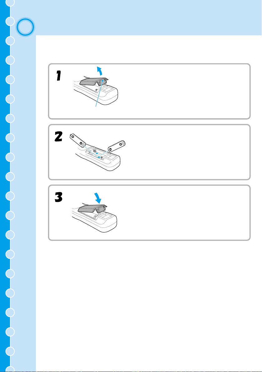
Inserting the Batteries
Battery Replacement Period and
Using the Remote Control
Remote Control Operating Range
START
2
Setup
Screen Size and Setting-up Distance
Setting-up Methods
Connecting to a Video Source
3
Connecting to a Computer
4
Printed in Japan
402167900
(9002465)
02.01-.6A(C05)
Page 2
Before Using the Remote Control
1
Inserting the Batteries
The batteries are not inserted into the remote control at the time of purchase, and so you
need to insert them before the remote control can be used.
Remove the battery compartment cover.
While pressing the cover here, lift the cover up.
Insert the batteries.
Make sure the polarities of the batteries are correct.
1
Replace the battery compartment cover.
After inserting the tab of the battery cover, push the
cover down until it clicks into place.
Page 3
Battery Replacement Period and
Using the Remote Control
Battery Replacement Period and Cautions
If the remote control becomes slow in responding or if it stops working, the batteries may
be spent. If this happens, replace the batteries with fresh ones.
Guide for battery replacement: Approximately 3 months if used for 30
minutes per day
*The replacement period given above may vary depending on the amount of usage and
the ambient conditions.
Use the following type of batteries as replacements.
Alkaline dry cell LR6 (AA) x 2
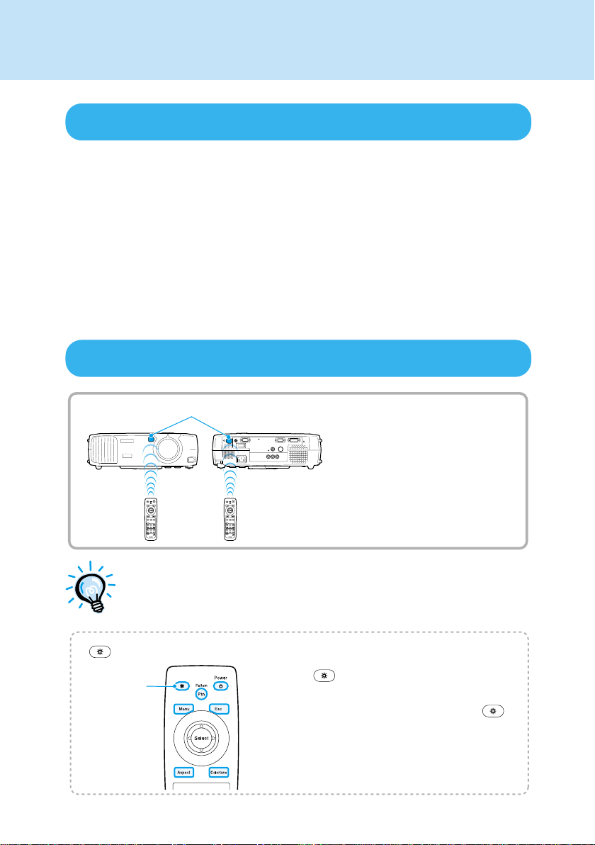
Using the Remote Control
Remote control light-receiving area
Point the remote control
light-emitting area toward one of
the remote control light-receiving
area on the projector and operate
the remote control buttons.
2
Do not allow sunlight or light from fluorescent lamps to shine directly
onto the projector's remote control light-receiving area, otherwise it may
interfere with the reception of signals from the remote control.
(illumination) button
illumination
button
When the button is pressed, the buttons
shown in colour in the illustration at left are
illuminated for 10 seconds. If you press the
button again during this 10-second period, the
illumination continues for another 10 seconds.
Page 4
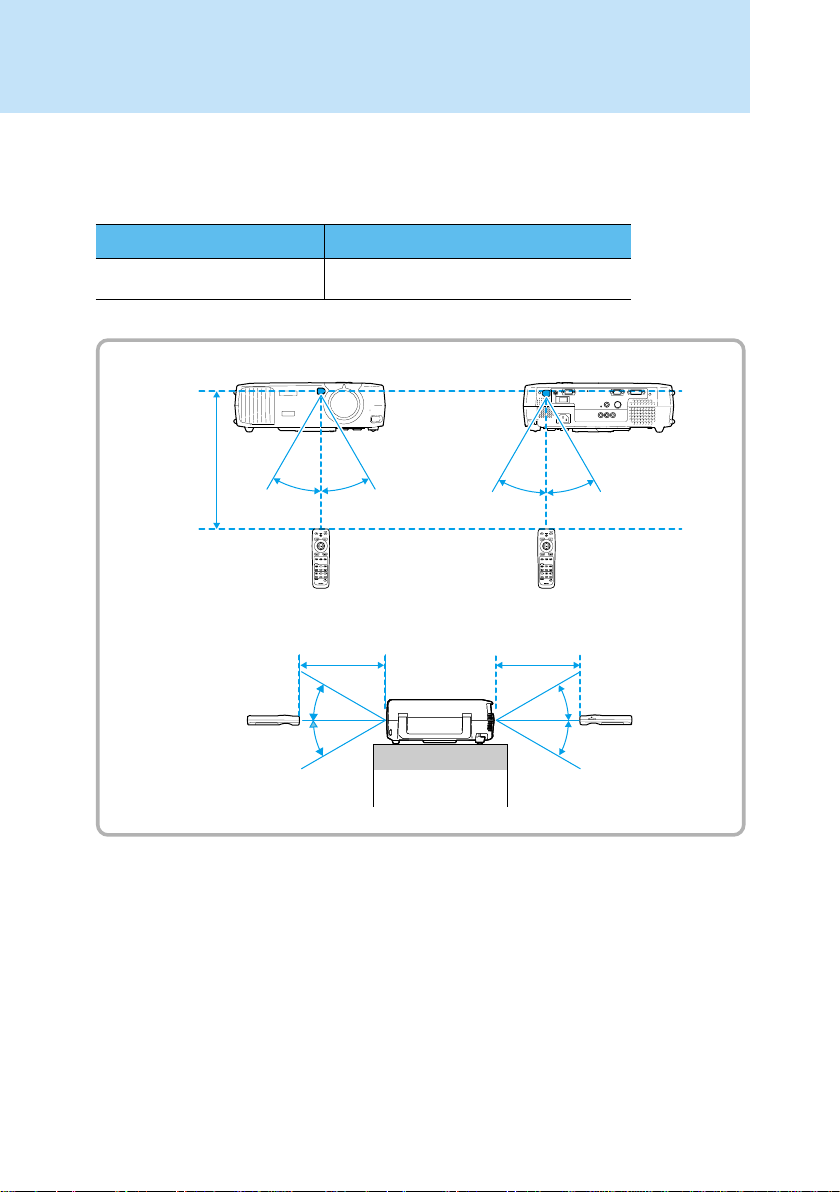
Remote Control Operating Range
Use the remote control within the ranges indicated below. If the distance or angle between
the remote control and the remote control light-receiving area is outside the normal
operating range, the remote control may not work.
Operating distance
Approx. 10 m (30 ft) Approx. 30˚ vertically and horizontally
Operating angle
Approx. ±30˚ horizontally
Approx.
10 m
(30 ft)
Approx. 30˚
Approx. 30˚ Approx. 30˚ Approx. 30˚
Approx. ±30˚ vertically
Approx. 10 m
(30 ft)
Approx. 30˚
Approx. 30˚
Approx. 10 m
(30 ft)
Approx. 30˚
Approx. 30˚
3
Page 5

Setup
2
Screen Size and Setting-up Distance
The distance between the projector and the screen determines the actual image size.
Recommended distance : 0.9m - 13.0m (2.9 - 42.6 feet)
While referring to the table below, position the projector so that the image size is smaller
than the screen size.
Screen size (cm (feet))
30"
(66 × 37 (2.1 × 1.2))
40"
(89 × 50 (2.8 × 1.6))
60"
(130 × 75 (4.2 × 2.4))
80"
(180 × 100 (5.7 × 3.2))
100"
(220 × 120 (7.2 × 4.1))
200"
(440 × 250 (14.4 × 8.2))
300"
(660 × 370 (21.6 × 12.1))
* Distance and dimensions should be used as a guide for installation. The actual distance will vary depending on
projection conditions.
0.2 m
(7.8 inches)*
Distance from center
of lens to bottom edge
of screen (cm)
* When installing to a wall, leave a space of about 0.2 m (7.8 inches)
between the projector and the wall.
Approximate projection
distance* (m (feet))
0.9 – 1.2
(2.9 – 3.9)
1.2 – 1.6
(3.9 – 5.2)
1.8 – 2.5
(5.9 – 8.2)
2.5 – 3.4
(8.2 – 11.1)
3.1 – 4.3
(10.1 – 14.1)
6.3 – 8.6
(20.6 – 28.2)
9.5 – 13.0
(31.1 – 42.6)
3.1 – 4.3
2.5 – 3.4
1.8 – 2.5
1.2 – 1.6
0.9 – 1.2
30"
(66 × 37)
5.1
|
5.0
9.5 – 13.0
6.3 – 8.6
40"
(89 × 50)
6.8
|
6.7
Distance in Fig.
A below (cm (feet))
5.0 – 5.1
(0.16 – 0.17)
6.7 – 6.8
(0.22 – 0.22)
10.2
(0.33)
13.6 – 13.7
(0.45 – 0.45)
17.0 – 17.1
(0.56 – 0.56)
34.0 – 34.3
(1.12 – 1.13)
51.0 – 51.4
(1.67 – 1.69)
80"
(180 × 100)
60"
(130 × 75)
13.7
10.2
13.6
|
100"
(220 × 120)
17.1
|
17.0
200"
(440 × 250)
34.3
|
34.0
Screen size
300"
(660 × 370)
51.4
|
51.0
A
4
The projector’s lens allows a zoom ratio of up to about 1.35. The
image size at the maximum zoom setting is about 1.35 times bigger
than the image size at the minimum zoom setting.
The image size will be reduced when keystone correction is carried
out.
Page 6

Setting-up Methods
The projector supports the following five projection methods, allowing you to choose the
best method for displaying your images.
After setting up the projector, refer to the User's Guide for details on turning on the power
and adjusting settings such as the screen size. ( "Basic Operations" in User's Guide)
When setting up the projector, be sure to first read the
Instructions/World-Wide Warranty Terms
for information on the safety
precautions that must be observed at this time.
Front projection
Front/ceiling projection
Rear projection using a
translucent screen
Projecting from locations such as the
top of a cabinet
When installing the projector upside down, set
the Screen Mode command in the Settings
environment setting menu to "Front/Ceiling".
("Settings" menu in User's Guide)
Safety
Rear projection onto a
translucent screen with the
projector installed to the ceiling
5
* A special method of installation is required in order to suspend the projector from the ceiling. Please
contact the place of purchase if you would like to use this installation method.
* When installing to the ceiling or projecting from behind the screen, set the Screen Mode command in the
Settings environment setting menu to match the method of projection being used.
"Settings" menu in User's Guide)
(
When turning the projector upside
Rubber stands
(Attach in
3 places)
down, attach the rubber stands that
are included.
This can prevent the control panel
from directly touching the
installation surface.
Page 7

Connecting to a Video Source
3
Turn off the power for both the projector and the video source before connecting them.
If the power for either device is on at the time of connection, damage may result.
Check the shapes of the cable connectors and the device ports before making the
connections. If you try to force a connector to fit a device port with a different shape or
number of terminals, a malfunction or damage to the connector or port may result.
Refer to the Optional Accessories appendix in the separate User's Guide for details of the
optional cables.
Projecting Component Video Images
If connecting using a component video cable (commercially-available)
To video output port
Green
Blue
Red
6
Component video cable
(commercially-available)
If connecting using a component video cable (optional)
To Input B port
To video output port
Component video cable (optional)
If more than one peripheral device is being connected to the projector,
make the connections and then change the Input A and Input B commands
in the Advanced environment setting menu to "YCbCr" or "YPbPr" to match
the signals from these devices. ("Advanced" menu in
For HDTV (750p or 1125i), "YPbPr" will be selected regardless of the above
setting.
For SDTV(525i,625i), "YCbCr" will be selected regardless of the above setting.
To Input A port
User's Guide
)
Page 8

Projecting Composite Video Images
To video output port
(yellow)
RCA video cable (yellow)
(commercially-available)
Projecting S-Video Images
To video output port
To Video port (yellow)
To S-Video port
7
S-Video cable
(commercially-available)
Page 9

Projecting RGB Video Images
If connecting using a computer cable (optional)
To RGB output port
Computer cable
(optional)
After connecting, use the environment setting menus to change the "Input B"
setting in the "Advanced" menu to "RGB".
("Advanced" menu in
User's Guide
)
To Input B port
If connecting using a DVI analog cable (optional)
To RGB output port
To A-RGB/D-RGB DVI-I port
8
ELPKC25 DVI analog cable
(optional)
Page 10

Connecting to a Computer
4
The projector cannot be connected to some types of computer, or projection of images
may not be possible even if actual connection is possible. Make sure that the computer you
intend to use satisfies the conditions given below.
Condition 1: The computer must have a image signal output port.
Check that the computer has a port such as an RGB port, monitor port or video port which
can output image signals. If the computer has a built-in monitor, or if using a laptop
computer, it may not be possible to connect the computer to the projector, or alternatively
you may need to purchase a separate external output port. Refer to the User's Guide for
your computer under a heading such as "Connecting an external monitor" or similar for
further details.
Condition 2: The display resolution and frequency of the computer must be listed
in the "List of Supported Signal Resolutions".
Some computers may have functions for changing the output resolution. Refer to the
User's Guide for the computer and change the setting to within a range given in the list of
supported resolutions.
Turn off the power for both the projector and the computer before connecting them.
If the power for either device is on at the time of connection, damage may result.
Check the shapes of the cable connectors and the device ports before making the
connections. If you try to force a connector to fit a device port with a different shape
or number of terminals, damage to the connector or port may result.
9
You may need to purchase a separate adapter to connect the
computer to the projector, depending on the shape of the computer's
monitor port. Refer to the
The optional Mac Adapter Set is required in order to connect the
projector to a Macintosh computer.
User's Guide
for the computer for details.
Page 11

If connecting using a computer cable
To monitor port
(video port)
Computer cable
(optional)
If connecting more than one projector together, make the connection
and then use the environment setting menus to change the "Input B"
setting in the "Advanced" menu to "RGB".
("Advanced" menu in
User's Guide
)
If the computer is equipped with a DVI or DFP-compliant digital video card or video output port
To A-RGB/D-RGB port
To Input B port
10
To monitor port
(video port)
DVI analog cable
(optional)
Do not bind the power cord together with the computer cable or DVI analog
cable, otherwise it may cause interf erence in the projected images or
operating errors.
 Loading...