

Page 1
Before Using the Remote Control
1
Inserting the Batteries
Using the Remote Control
Remote Control Operating Range
START
2
Setup
Screen Size and Setting-up Distance
Setting-up Methods
Connecting to a Video Source
3
Connecting to a Computer
4
Printed in Japan
402171600
(9002555)
02.02-.6A(C05)
Page 2
1
Before Using the Remote Control
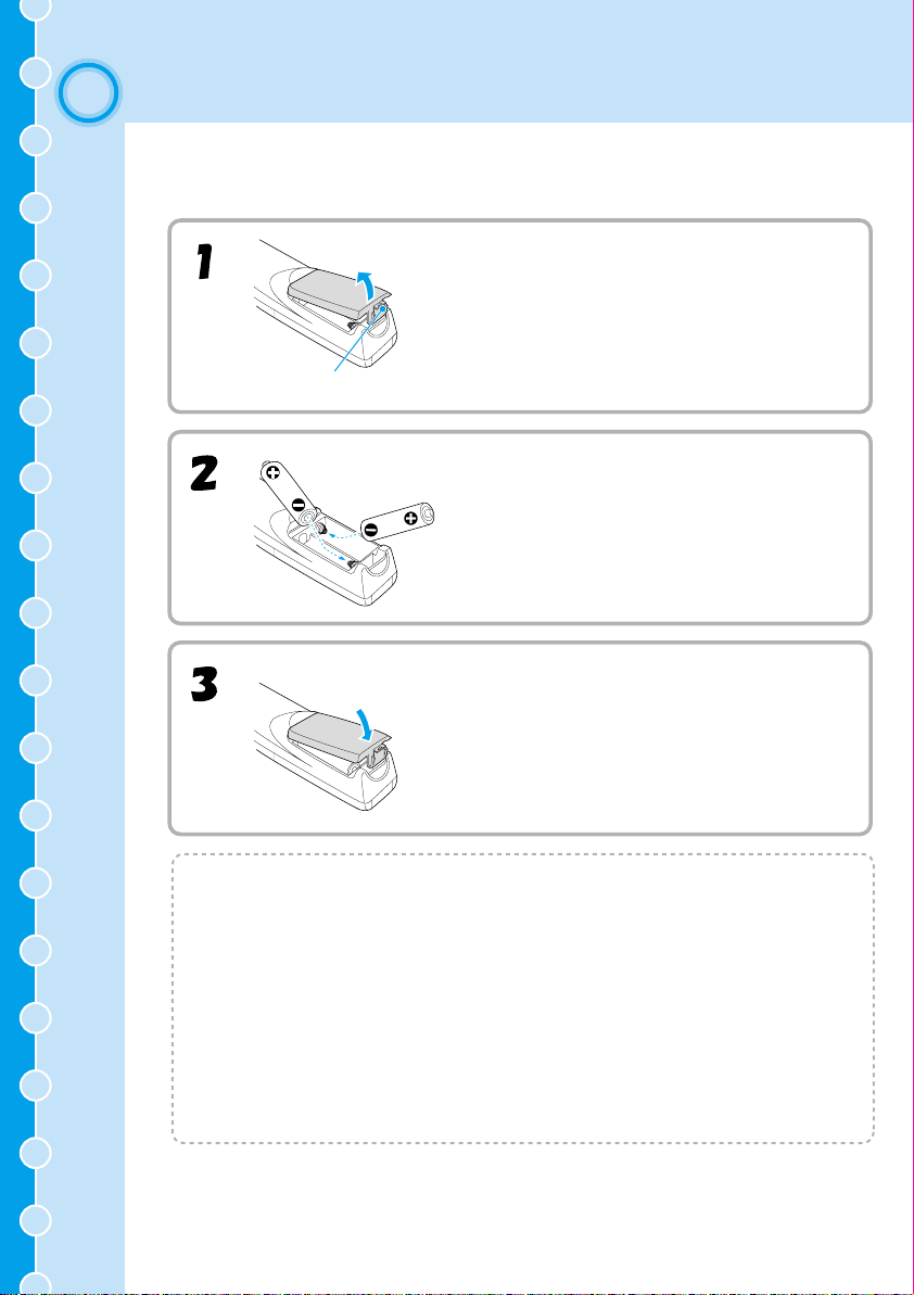
Inserting the Batteries
The batteries are not inserted into the remote control at the time of purchase, and so you
need to insert them before the remote control can be used.
Remove the battery compartment cover.
While pressing the cover here, lift the cover up.
Insert the batteries.
Make sure the polarities of the batteries are correct.
Replace the battery compartment cover.
After inserting the tab of the battery cover, push the
cover down until it clicks into place.
1
Battery Replacement Period and Cautions
If the remote control becomes slow in responding or if it stops working, the batteries
may be spent. If this happens, replace the batteries with fresh ones.
Guide for battery replacement: Approximately 3 months if used for 30
minutes per day
*The replacement period given above may vary depending on the amount of usage
and the ambient conditions.
Use the following type of batteries as replacements.
Alkaline dry cell LR6 (AA) x 2
Page 3
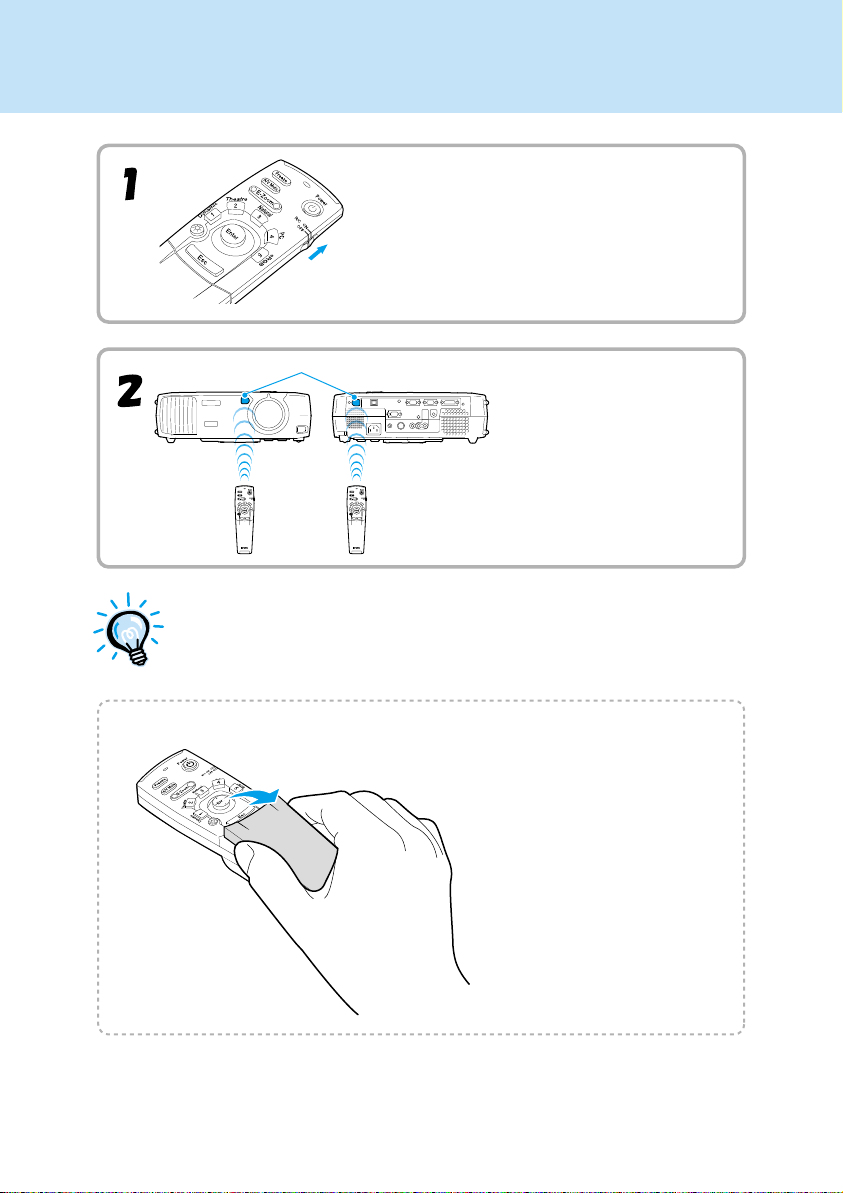
Using the Remote Control
Set the R/C switch on the remote control to
the ON position.
Remote control light-receiving area
Point the remote control
light-emitting area toward one of
the remote control lightreceiving area on the projector
and operate the remote control
buttons.
Do not allow sunlight or light from fluorescent lamps to shine directly
onto the projector's remote control light-receiving area, otherwise it may
interfere with the reception of signals from the remote control.
Opening the cover
2
Hold the cover on both
sides.
Page 4
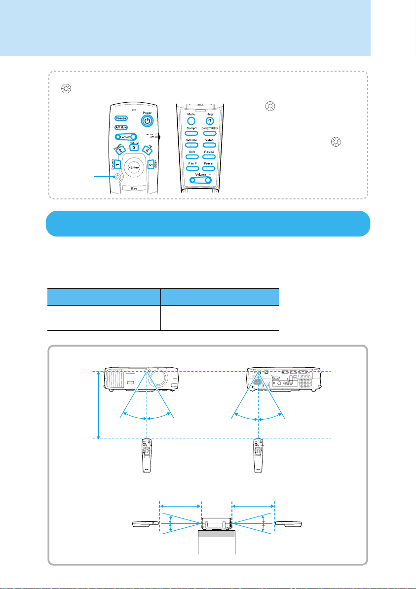
Remote Control Operating Range
(illumination) button
When the button is pressed, the
buttons shown in colour in the
illustration at left are illuminated for
10 seconds. If you press the
button while the buttons are
illumination
button
Remote Operating Range
Use the remote control within the ranges indicated below. If the distance or angle between
the remote control and the remote control light-receiving area is outside the normal
operating range, the remote control may not work.
illuminated, the illumination will
continue for a further 10 seconds.
3
Operating distance
Approx. 10 m (30 ft.)
Approx. ±30˚ horizontally
Approx. 10 m
(30 ft.)
Approx. ±15˚ vertically
Approx. 15˚
Approx. 15
Operating angle
Approx. ±30˚ horizontally
Approx. ±15˚ vertically
Approx. 30˚ Approx. 30˚ Approx. 30˚Approx. 30˚
Approx. 10 m
(30 ft.)
Approx. 10 m
(30 ft.)
Approx. 15˚
Approx. 15˚
Page 5
2
Screen Size and Setting-up Distance
Setup
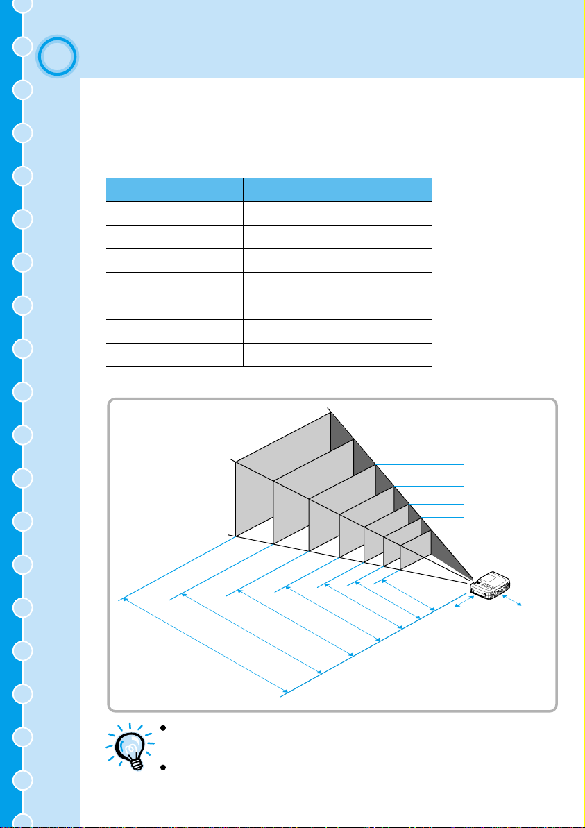
The distance between the projector and the screen determines the actual image size.
Recommended distance : 0.9m - 12.4m (3.0 - 40.7 ft.)
While referring to the table below, position the projector so that the image size is smaller
than the screen size.
30” (61 × 46 (2.0 × 1.5))
40” (81 × 61 (2.7 × 2.0))
60” (120 × 90 (3.9 × 3.0))
80” (160 × 120 (5.3 × 3.9))
100” (200 × 150 (6.6 × 4.9))
200” (410 × 300 (13.5 × 9.8))
300” (610 × 460 (20.0 × 15.1))
* The value for the projection distance should be used as a guide for setting up the projector.
The actual distance will vary depending on projection conditions.
Screen size (cm (ft.))
Approximate projection
distance* (m (ft.))
0.9 – 1.1 (3.0 – 3.6)
1.2 – 1.6 (3.9 – 5.2)
1.8 – 2.4 (5.9 – 7.9)
2.5 – 3.2 (8.2 – 10.5)
3.1 – 4.1 (10.2 – 13.5)
6.1 – 8.3 (20.0 – 27.2)
9.2 – 12.4 (30.2 – 40.7)
300”
4
200”
100”
80”
60”
40”
30”
20 cm
(7.9 inches)*
20 cm
(7.9 inches)*
9.2 – 12.4(m)
6.1 – 8.3
460 (cm)
×
610
3.1 – 4.1
300
×
410
2.5 – 3.2
200×150
160×120
120×90
81×61
61×46
0.9 – 1.1
1.2 – 1.6
1.8 – 2.4
* When installing against a wall, leave a
space of about 20 cm (7.9 inches) between
the projector and the wall.
The projector’s lens allows a zoom ratio of up to about 1.35. The
image size at the maximum zoom setting is about 1.35 times bigger
than the image size at the minimum zoom setting.
The image size will be reduced when keystone correction is carried
out.
Page 6
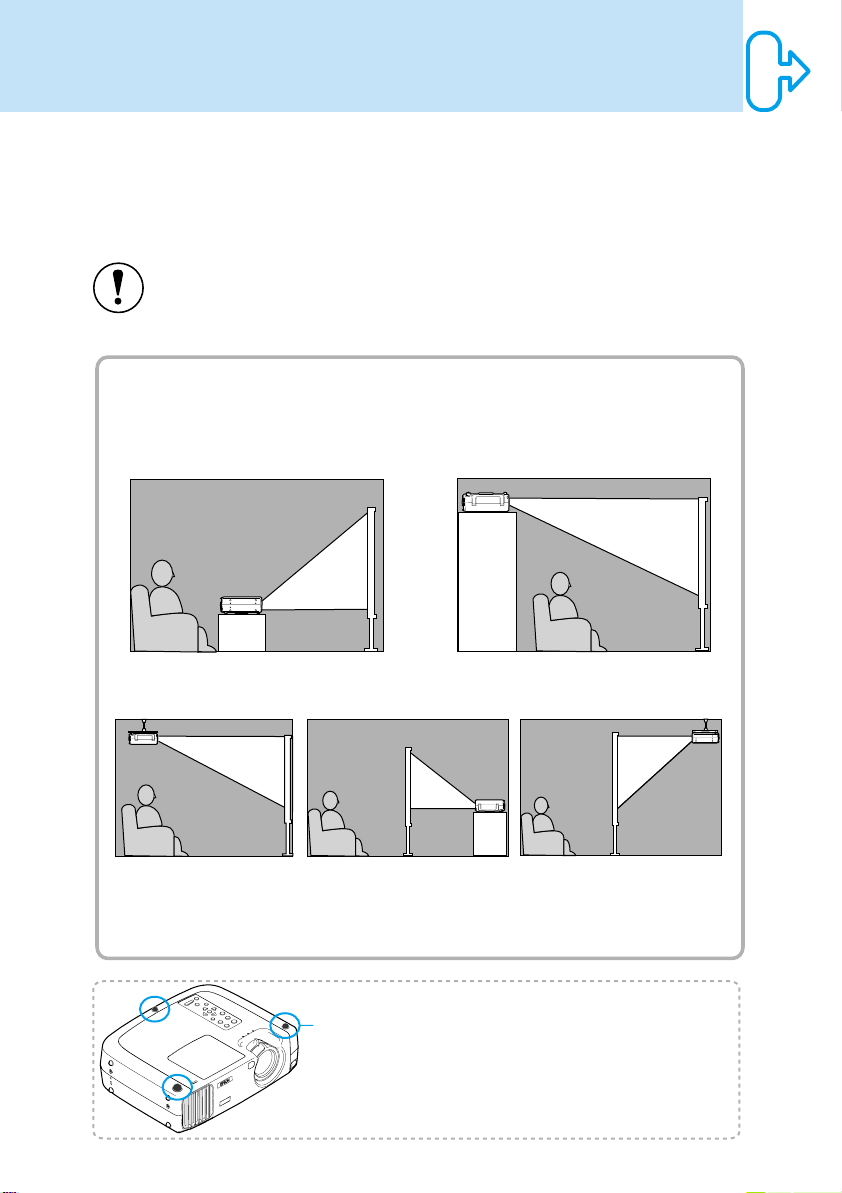
Setting-up Methods
The projector supports the following five projection methods, allowing you
to choose the best method for displaying your images.
After setting up the projector, refer to the User's Guide for details on turning
on the power and adjusting settings such as the screen size.
("Basic Operations" in User's Guide)
When setting up the projector, be sure to first read the
Instructions/World-Wide Warranty Term
s for information on the
safety precautions that must be observed at this time.
Safety
Continued
Front projection
Rear projection using a
Front/ceiling projection
* A special method of installation is required in order to suspend the projector from the ceiling. Please
contact the place of purchase if you would like to use this installation method.
* When projecting with the projector installed upside down or behind the screen, turn on both the "Rear
Proj." and "Ceiling" settings in the "Advanced" menu.
("Advanced" menu in User's Guide)
translucent screen
Projecting from locations such as the
top of a cabinet
When installing the projector upside down, set
the "Ceiling" command in the "Advanced"
menu.
("Advanced" menu in User's Guide)
Rear projection onto a
translucent screen with the
projector installed to the ceiling
5
Rubber stands
(Attach in
3 places)
When turning the projector upside
down, attach the rubber stands that
are included.
This can prevent the control panel
from directly touching the
installation surface.
Page 7
3
Connecting to a Video Source
Turn off the power for both the projector and the video source before connecting them.
If the power for either device is on at the time of connection, damage may result.
Check the shapes of the cable connectors and the device ports before making the
connections. If you try to force a connector to fit a device port with a different shape or
number of terminals, a malfunction or damage to the connector or port may result.
Refer to the "Appendices - Optional Accessories" in the separate User's Guide for details
of the optional cables.
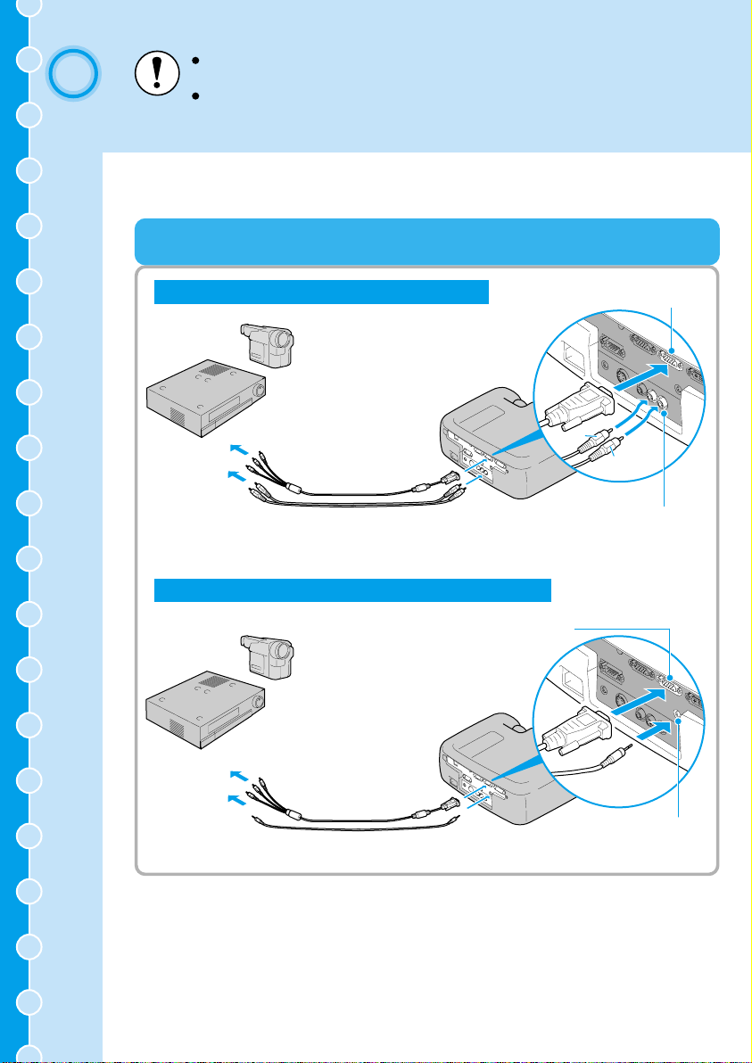
Projecting Component Video Images
When audio output is via a 2RCA audio cable
To video
output port
Component video cable
(accessory)
To audio output
L port (white)
To audio output
R port (red)
2RCA audio cable (white/red)
(commercially-available)
When audio output is via a stereo mini-pin audio cable
To Computer 2/Component
Video port
To video
output port
To audio
output port
Component video cable
(accessory)
Stereo mini-pin audio cable
(commercially-available)
To Computer 2/Component
Video port
white
red
To Audio 2 port
(white/red)
To Audio 1 port
6
Page 8

After making the connections, change the "Comp2/YCbCr Input" in the
"Setting" menu to either "YCbCr" or "YPbPr" to match the signals from
these devices. ("Setting" menu in
After making the connections, change the "Audio Input" setting in the
"Audio" menu to either "Audio1" or "Audio2", depending on which input
port you are using.
User's Guide
)
7
Page 9

Projecting Composite Video Images
When connected via a 3RCA A/V cable
To Audio 2 port (white/red)
To Video port (yellow)
yellow
To video output port (yellow)
To audio output L port (white)
To audio output R port (red)
3RCA A/V cable
(commercially-available)
When connected via an RCA video cable and a stereo mini-pin audio cable
To Audio 1 port
To Video port (yellow)
To video output
port (yellow)
To audio output
port
RCA video cable (yellow)
(commercially-available)
Stereo mini-pin audio cable
(commercially-available)
white
red
8
After making the connections, change the "Audio Input" setting in the
"Audio" menu to either "Audio1" or "Audio2", depending on which
input port you are using. The default setting is "Audio2".
Page 10

Projecting S-Video Images
When audio output is via a 2RCA audio cable
To Audio 2 port
To S-Video port
(white/red)
To video output
port
To audio output
L port (white)
To audio output
R port (red)
S-Video cable
(commercially-available)
2RCA audio cable (white/red)
(commercially-available)
When audio output is via a stereo mini-pin audio cable
To Audio 1 port
To S-Video port
To video output
port
To audio output
port
S-Video cable
(commercially-available)
Stereo mini-pin audio cable
(commercially-available)
After making the connections, change the "Audio Input" setting in the
"Audio" menu to either "Audio1" or "Audio2", depending on which
input port you are using. The default setting is "Audio2".
white
red
9
Page 11

Projecting RGB Video Images
When connecting to the Computer 2/Component Video port
(Example: When audio output is via a 2RCA audio cable)
To Computer 2/Component
Video port
To RGB output
port
Computer cable (optional)
To audio output
L port (white)
To audio output
R port (red)
2RCA audio cable (white/red)
(commercially-available)
When connecting to the Computer 1 port
(Example: When audio output is via a stereo mini-pin audio cable)
To Audio 1 port
To audio output
port
2Stereo mini-pin audio cable
To RGB output
port
(commercially-available)
ELPKC25 DVI analog cable
(optional)
white
red
To Audio 2 port
(white/red)
To Computer 1 port
10
Page 12
Continued on
the back page
RGB video is only compatible with sync-in-green signals. This can be
checked by looking at "Sync. Mode" in the "About" menu.
After making the connections, change the "Comp1 Input" or "Comp2
/YCbCr Input" setting in the "Setting" menu to "RGB Video".
For separate sync (separate H-SYNC and V-SYNC) signals, set to
"Analog-RGB". ("Setting" menu in
This can be checked by looking at "Sync. Mode" in the "About" menu.
After making the connections, change the "Audio Input" setting in the
"Audio" menu to either "Audio1" or "Audio2", depending on which
input port you are using. The default setting is "Audio2".
For a RGB connection, a commercially available adapter or converter
cable might be required.
User's Guide
)
Page 13
Turn off the power for both the projector and the computer before connecting them. If
4
Connecting to a Computer
The projector cannot be connected to some types of computer, or projection of images
may not be possible even if actual connection is possible. Make sure that the computer
you intend to use satisfies the conditions given below.
Condition 1: The computer must have a image signal output port.
Check that the computer has a port such as an RGB port, monitor port or CRT port which
can output image signals. If the computer has a built-in monitor, or if using a laptop
computer, it may not be possible to connect the computer to the projector, or alternatively
you may need to purchase a separate external output port. Refer to the documentation for
your computer under a heading such as "Connecting an external monitor" or similar for
further details.
Condition 2: The display resolution and frequency of the computer must be listed
in the "Appendices - List of Supported Signal Resolutions".
Some computers may have functions for changing the output resolution. For details, refer
to the section of the documentation provided with your computer and change the setting to
within a range given in the list of supported resolutions.
the power for either device is on at the time of connection, damage may result.
Check the shapes of the cable connectors and the device ports before making the
connections. If you try to force a connector to fit a device port with a different shape
or number of terminals, damage to the connector or port may result.
You may need to purchase a separate adapter to connect the
computer to the projector, depending on the shape of the computer's
monitor port. For details, refer to the section of the documentation
provided with your computer.
The commercially available adapter set is required in order to connect
the projector to a Macintosh computer.
11
Page 14

If connecting using a computer cable
To monitor port
Computer cable
(optional)
If more than one external component is connected to the projector,
change the "Comp2/YCbCr Input" or "Comp1 Input" setting in the
"Setting" menu to "Analog-RGB" after making the connections.
("Setting" menu in
User's Guide
)
If the computer is equipped with a DVI or DFP-compliant digital video card or video output port
To Computer2/Component
Video port
To Computer 1 port
12
To monitor port
Digital video
cable or
DVI analog cable
(optional)
Do not bind the power cord together with the computer cable or Digital
video cable or DVI analog cable, otherwise it may cause interference in
the projected images or operating errors.
Page 15

Playing Sound from the Computer
When audio output is via a 2RCA audio cable
To audio output L port (white)
To audio output R port (red)
2RCA audio cable (white/red)
(commercially-available)
When audio output is via a stereo mini-pin audio cable
To audio output port
white
red
To Audio 2 port
(white/red)
13
Stereo mini-pin audio cable
(commercially-available)
To Audio 1 port
Page 16

When audio output is via a USB cable
To USB port
USB cable
(commercially-available)
After making the connections, change the "Audio Input" setting in the
"Audio" menu to either "Audio1", "Audio2" or "USB", depending on
which input port you are using. ("Audio" menu in
The USB cable can only be connected to computers with a standard
USB interface. If using a computer which is running Windows, the
computer must have had a full version of Windows 98/2000/Me
installed. If the computer is running a version of Windows 98/2000/Me
that has been upgraded from an earlier version of Windows, correct
operation cannot be guaranteed. If using a Macintosh computer, the
computer must be running OS9.0 – 9.1. It may not be possible to use
the USB audio function under some versions of both the Windows and
Macintosh operating systems.
If using a USB cable to output sound from the computer, you may
need to change the computer settings. For details, refer to the section
of the documentation provided with your computer.
To USB port
User's Guide
)
14
Page 17

Using the Remote Control to Operate the Mouse Pointer
The accessory remote control can be used as a wireless mouse.
To USB mouse port
USB cable (commercially-available)
Once the connection has been made, the mouse pointer can be operated
as follows.
To USB port
15
Moving the mouse pointer
Press the edge of the [Enter]
button to move the mouse
pointer in the direction of the
edge pressed. The [Enter]
button can be tilted in any
one of 16 directions.
Left click
Press the [Enter] button.
Right click
Press the [Esc] button.
Page 18

The USB cable can only be connected to computers with a standard USB
interface. If using a computer which is running Windows, the computer
must have had a full version of Windows 98/2000/Me installed. If the
computer is running a version of Windows 98/2000/Me that has been
upgraded from an earlier version of Windows, correct operation cannot be
guaranteed.
If using a Macintosh computer, the computer must be running
OS8.6 – 9.1.
It may not be possible to use the mouse function under some versions of
both the Windows and Macintosh operating systems.
Some computer settings may have to be changed in order for the mouse
function to be used. For details, refer to the section of the documentation
provided with your computer.
If the mouse button settings have been reversed at the computer, the
operation of the remote control buttons will also be reversed.
The wireless mouse function cannot be used when any of the following
functions are being used.
• During menu display • Before setting a P in P (Picture in Picture)
sub-screen
• E-Zoom • When image size is set to normal display (resizing off)
(for resolutions of SXGA and above)
16
Page 19

Connecting to an External Monitor
To Monitor Out port
Cable provided
Monitor port
A commercially available adapter might be required for connecting a
Macintosh computer.
Digital RGB signals that are being input to the Computer 1 port cannot
be output to an external monitor.
Video images cannot be output to an external monitor.
with monitor
Remove the cover attached to the Monitor Out
port before using it.
17
Page 20

Name and function of the projector operating panel buttons
[Power] button
Turns the projector power on and off.
[Computer/YCbCr] button
Changes the image source between the Computer 1 port
and the Computer 2/Component Video port.
[Menu] button
Displays or hides the menus.
[V-Keystone] button
Press this button if the projected image has vertical
keystone distortion.
If you press and hold the [Shift] button while pressing
this button, you can adjust the synchronization of
computer images.
[Shift] button
This button does not function by itself. Press and hold
this button while pressing either [Keystone] button to
activate the function that is printed in orange on the
control panel (Sync or Tracking).
Powe r
Computer/YCbCr
Menu Esc
Tracking - Tracking +
Shift
A/V Mute
Source
Sync+
Auto
Sync-
Resize
Help
Video
Keystone
Volume
[Help] button
Displays the online help menu to assist you if you have
a problem.
[Video] button
Changes the image source between the Video port and
the S-Video port.
[Esc] button
Press to cancel the function currently being used.
Pressing [Esc] while viewing an environment setting
menu or the online help displays the previous screen or
menu.
[Auto] button
Automatically adjusts the computer image to the
optimum image.
Functions as an button when an environment setting
menu or help screen is being displayed. Press to select
an item and proceed to the next screen.
[H-Keystone] button
Press this button if the projected image has horizontal
keystone distortion.
If you press and hold the [Shift] button while pressing
this button, you can adjust the tracking of computer
images.
[A/V Mute] button
Turns off the audio and video.
[Resize] button
Changes the aspect ratio.
[Volume] button
Adjusts the volume of the built-in speaker.
Page 21
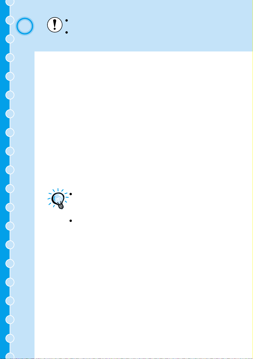
Name and function of the remote control buttons
Remote control light-emitting area
Outputs infrared remote control signals.
Underneath cover
[Freeze] button
Keeps the current computer or video image on the
screen.
[A/V Mute] button
Turns off the audio and video.
[E-Zoom] button
Enlarges or reduces the size of the image without
changing the size of the projection area.
Colortune button
Changes the color mode in accordance with the
button pressed.
[ (Illumination) ] button
All buttons other than the [Enter], [Esc] and
buttons illuminate for 10 seconds each time this
button is pressed.
Cover
Open to use the buttons that are underneath the
cover.
Indicator
Lights when a remote control signal is being
output.
[Power] button
Turns the projector power on and off.
R/C switch
Turns the remote control power on and off.
[Enter] button
If pressed when an environment setting menu or
help screen is being displayed, the menu item is
selected and the next menu screen appears.
If a computer is connected and the remote control
is being used as a wireless mouse, the button can
be tilted up, down and to the left or right to move
the pointer in the tilted direction. When pressed,
it functions in the same way as a left mouse
button.
[Esc] button
Press to cancel the function currently being used.
Pressing [Esc] while viewing an environment
setting menu or the online help displays the
previous screen or menu. If a computer is
connected and the remote control is being used as
a wireless mouse, it functions as a right mouse
button.
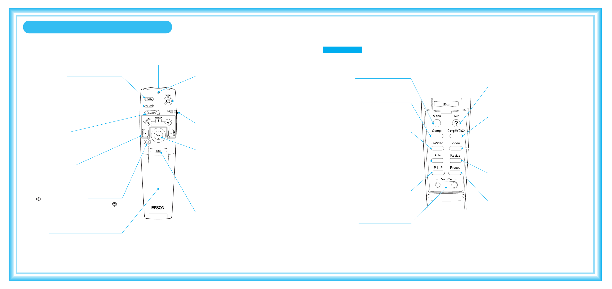
[Menu] button
Displays or hides the environment setting menus.
[Comp1] button
Changes the image source to the signals being
input to the Computer 1 port.
[S-Video] button
Switches to the images input from the S-Video
port.
[Auto] button
Automatically adjusts computer images to the
optimum images.
[P in P] button
Activates the P in P (Picture in Picture) function.
[Volume] button
Adjusts the volume of the built-in speaker.
[Help] button
Displays the online help menu.
[Comp2/YCbCr] button
Changes the image source to the signals being
input to the Computer 2/Component Video port.
[Video] button
Switches to the images input from the Video
port.
[Resize] button
Changes the aspect ratio.
[Preset] button
Selects one of the computer image resolutions
that have been preset.
 Loading...