

Epson EMP-7300 SERVICE Manual
EPSON EMP-7300 |
EPSON® |
|
Service Manual |
Revision: 3 Jun 1998 |
|
|
|
|
Front Cover |
Chapter 1 |
|
Introduction |
Product Description |
|
|
||
Precautions |
Chapter 2 |
|
Theory of Operation |
||
|
||
Index Pages |
Chapter 3 |
|
|
||
Specifications Section |
Disassembly & Assembly |
|
|
||
Back Cover |
Appendix |
Notes:-
∙Detailed circuit board component diagrams may be found in the Appendix section of this manual.
EPSON EMP-7300
Goto:-
Spares Guide
Select:-
? << <
ãEpson (UK) Ltd. 1998 |
Page: 1 of 1 |

EPSON DATA PROJECTOR
XGA Data Projector
SERVICE MANUAL
EMP-7300
EPSON
INTRODUCTION
This Service Manual describes of the hardware information which is necessary for the smooth field service of the XGA DATA PROJECTOR EMP-7300 and the trouble shooting.
As the primary technologies will be supplied with the service bulletin, you may update this manual.
HOW TO USE THE SERVICE MANUAL
Since the service manual describes the topics, which may be required in the field maintenance, you may utilize this for repair or diagnosis of failures. The contents are as following. Before you start the maintenance service, read every safety precautions and observe safety precautions and observe safety rules.
Precautions : SAFETY, MAINTENANCE, and PERSON
Chapter 1: GENERAL (PART NAME, SYSTEM FUNCTION, SPECIFICATION, etc.) Chapter 2: THEORY OF OPERATION (HARDWARE, INTERNAL CONNECTION,
and FUNCTION OF UNITS, etc.)
Chapter 3: DISASSEMBLE & ASSEMBLE (ASSEMBLY PROCESS FOR MAIN FRAME)
Chapter 4: TROUBLE SHOOTING
Appendix: PARTS LIST, EXPLODED DIAGRAM, CIRCUIT DIAGRAM, HARDWARE COMPARISON TABLE, etc.
VCCI RADIO FREQUENCY INTERFERENCE SELF RESTRICTION
This product is the type 1 information equipment and uses radio frequency energy and fully complies with the limits for the specifications in the computer information equipment radio interference regulation (VCCI rules). If not installed and used properly manufacturer's instructions, may cause interference to radio and television reception.
TRADEMARK
IBM and DOS/V are the trademark or the registered trademark of International Business Machines Corporation.
Macintosh and Power Book are the registered trademarks of Apple Computer Inc. Windows is the trademark of Microsoft Corporation.
EPSON is the trademark of SEIKO EPSON CORPORATION.
NOTICES
1.This document should not be reproduced in whole or in part without the written permission of SEIKO EPSON CORPORATION.
2.Any of description in this document is the subject to change without notice in future.
3.The information and specification in this document are the most up-to-date at the time of publication. However, we are unable to guarantee the accuracy of printed material after the date of publication. In case of any mistake or lack of description, please kindly notify us to correct.
4.Any influence by utilizing the document may be out of our responsibility regardless the item 3 above.
©1998 SEIKO EPSON CORPORATION

Record of Revisions
History |
Issued Date |
Alternation |
|
|
|
REVA |
1998,February.13 |
Preliminary Issued |
|
|
|
|
|
|
|
|
|
|
|
|
Memo Random
Free area to memorize any important technical information here.
PRECAUTIONS
1. MAINTAIN THE SAFETY OF OPERATORS
(1) PROTECTION FROM ELECTRIC SHOCK
*Whenever doing any repair work on the product, be sure to turn off the power switch and remove the electric power cable from the electrical outlet.
*Whenever inevitably turning the power on to the product opening the case or cover (repair process) be sure to take off any metallic materials such as a watch, cuffs, rings, and tie pins which may touch the metallic part of the product and dangerous of electric shock.
(2) PROTECTION FROM ACCIDENTAL INJURY
*Be sure not to touch the lamp inner housing and its circumstances after the power is turned off, they may be heated up even after the cooling down process was ended. Also make sure not to touch the light source and its circumstances during the operation of repair as turning the power on.
*Make sure to protect your hands by gloves from sharp edges during assembly and disassembly.
*Do not look into the light source or lens while the light is on. Protect eyes from being damaged.
(3) PROTECTION FROM ACCIDENTS
*Any operation should be done while the device placed on a flat and stable place to prevent the device or parts from being dropped. Be careful not to place tools and parts on the device or at your feet.
*Whenever doing any repair work on the product, be sure to away from a place for foreigner come across in order to prevent the product from being used in incomplete condition or accidental near miss. Be sure not to leave the product during any repair work.
*Be sure to use attached power cable when you supply the power to the product.
2. SAFETY MAINTENANCE
(1) ELECTROSTATIC DISCHARGE
* Whenever doing any repair work on the product, be sure to wear the wristband and the electrostatic mat with grounding. When replacing any electric components (Boards and Optical engine), it is recommended to touch the electrostatic plastic bag of the component to the metallic part of the product once before take the component out from the plastic bag.

(2) LIMITATION OF PARTS
* Use only authorized or supplied parts from EPSON for the replacement of mechanical parts including the lamp inner housing, fuse, air filter and so on.
* Use only the power cable and the interface cables attached with the product.
(3) Others
*Visually checks the distortion or dirt at the connectors of the power cable. If dirty, clean off, and if distorted, replace the cable in order to avoid firing by the flush over phenomenon.
*When plug the internal connector cables or the interface cables, be sure to fully plug into the connectors until it stack to the connector edge.
*When remove the FPC cable of the light valve are sure to remove the connector lock in advance. The connector lock should be unlocked by pulling up the both end of connector lock simultaneously with tweezers.
*Whenever doing removal of parts or repair work on the product, make sure that the work is done in a clean room, free of dust and dirt in order to keep the optical element away from dirt.
3. REQUIREMENT FOR THE MAINTENANCE PERSON
Authorized person should have the following knowledge and skill for the maintenance of EMP-7300.
*Need to be trained by EPSON authorized maintenance training program and to be authorized as a service engineer.
*Need to sufficiently understand the operation and the descriptions of this service manual.
*Need to have the basic knowledge of electricity (safety operation, circuit diagram, electrostatic, and else...)
4. OTHERS
* Any questions on the RS-361/RS-376 maintenance including supply of the service parts or contents of the document would like to be contacted to the below address. Any technical information about amendments is occasionally available as the service bulletin.
SEIKO EPSON CORPORATION 4897 OH-AZA SHIMAUCHI,
MATSUMOTO-SHI, NAGANO-KEN 390 JAPAN TEL: 81-263-47-5603
FAX: 81-263-48-5680
ATTN: Visual Device Customer Support Group
Contents
Chapter 1
Product general
1.1 PRODUCT GENERAL ................................................................................ |
1-1 |
1.2 PART NAME............................................................................................... |
1-2 |
1.2.1 Outside View of Main Frame ............................................................. |
1-2 |
1.2.2 Inside View of Main Frame................................................................ |
1-3 |
1.2.3 Outside View of Remote Controller ................................................... |
1-7 |
1.3 CONNECTION............................................................................................ |
1-8 |
1.3.1 Connecting to a PC ........................................................................... |
1-8 |
1.3.2 Connecting to a Macintosh................................................................ |
1-9 |
1.3.3 Connecting to a Video source ......................................................... |
1-10 |
1.3.4 Connecting to an Audio source ....................................................... |
1-10 |
1.4 MAIN COMPORNENT .............................................................................. |
1-11 |
1.5 SPECIFICATIONS .................................................................................... |
1-15 |
1.6 INTERFACE SPECIFICATION ................................................................. |
1-17 |
1.6.1 Computer 1/2 .................................................................................. |
1-17 |
1.6.2 Audio 1/2......................................................................................... |
1-18 |
1.6.3 Audio Out ........................................................................................ |
1-18 |
1.6.4 S-Video ........................................................................................... |
1-18 |
1.6.5 Video............................................................................................... |
1-19 |
1.6.6 Audio L/R ........................................................................................ |
1-19 |
1.6.7 Mouse / Com 1/2............................................................................. |
1-19 |
1.6.8 Receptor ......................................................................................... |
1-20 |
1.6.9 RGB Video Input (EHQ option I/F)................................................... |
1-20 |
Chapter 2
Theory of operation
2.1 HARDWARE............................................................................................... |
2-1 |
2.1.1 Electrical System Connections .......................................................... |
2-2 |
2.1.2 Optical System Connections (Optical Engine) ................................... |
2-3 |
2.2 POWER SUPPLY UNIT .............................................................................. |
2-5 |
2.3 CD10MA BOARD ....................................................................................... |
2-8 |
2.4 CD10DR BOARD...................................................................................... |
2-11 |
2.5 SWITCH PANEL....................................................................................... |
2-14 |
2.6 CD10AU BOARD...................................................................................... |
2-15 |
2.7 CD10MJ BOARD ...................................................................................... |
2-17 |
2.8 CD10AJ BOARD....................................................................................... |
2-19 |
2.9 CD10VJ BOARD....................................................................................... |
2-20 |
2.10 CD10PJ BOARD..................................................................................... |
2-21 |
2.11 CD10RC BOARD (RECEPTOR BOARD) ............................................... |
2-22 |
2.12 SPEAKER UNIT...................................................................................... |
2-24 |
2.13 LIGHT GUIDE UNIT................................................................................ |
2-25 |
2.14 LAMP INNER HOUSING ........................................................................ |
2-27 |
2.15 SENSOR / SWITCH................................................................................ |
2-30 |
2.15.1 Interlock Switch ............................................................................. |
2-31 |
2.15.2 Safety Switch ................................................................................ |
2-32 |
2.15.3 Lamp House Thermistor................................................................ |
2-33 |
2.15.4 LV Thermistor ............................................................................... |
2-34 |
2.15.5 Front Temperature Thermistor ...................................................... |
2-35 |
Chapter 3
Disassembly and assembly
3.1 DISASSEMBLY AND ASSEMBLY PROCEDURES .................................... |
3-1 |
3.2 DISASSEMBLING THE MAIN UNIT............................................................ |
3-5 |
3.2.1 Removing the Lamp Inner Housing ................................................... |
3-6 |
3.2.2 Removing the Air Filter Frame Unit ................................................... |
3-7 |
3.2.3 Removing the Upper Case Unit And Handle ..................................... |
3-8 |
3.2.4 Removing the Switch Panel ............................................................ |
3-10 |
3.2.5 Removing the Speaker Units Right / Left......................................... |
3-11 |
3.2.6 Removing the CD10AU Board......................................................... |
3-12 |
3.2.7 Removing the Receptor Board Assembly (FI Board / RI Board) ...... |
3-13 |
3.2.8 Removing the CD10MA Board ........................................................ |
3-14 |
3.2.9 Removing the Rear Case Unit Assembly ........................................ |
3-16 |
3.2.10 Removing the CD10AJ/CD10MJ/CD10PJ/CD10VJ Board ............ |
3-17 |
3.2.11. Removing the Lamp Thermistor ................................................... |
3-19 |
3.2.12. Removing the Prism Duct / LV Thermistor.................................... |
3-20 |
3.2.13. Removing the Safety Switch......................................................... |
3-21 |
3.2.14. Removing the Optical Engine ....................................................... |
3-22 |
3.2.15. Removing the Power Supply Unit / PBS Thermistor ..................... |
3-23 |
3.2.16. Removing the Foot Adjuster A/B .................................................. |
3-25 |
3.2.17. Removing the CD10DR Board Assembly ..................................... |
3-26 |
3.2.18. Removing the FC Board............................................................... |
3-27 |
3.2.19. Removing the Projection Lens Unit (PLU) .................................... |
3-28 |
3.2.20. Removing the Cooling Fan / Optical Head Unit / Light Guide |
|
Unit/Exhaust fan....................................................................................... |
3-29 |
Chapter 4
Troubleshooting
4.1. Before Starting Troubleshooting Procedures.............................................. |
4-1 |
4.1.1. Tools and Accessories Required for Troubleshooting ...................... |
4-1 |
4.1.2. Field Replacement Parts .................................................................. |
4-1 |
4.2. Entry .......................................................................................................... |
4-2 |
Appendix
Parts table
Circuit diagram
Exploded diagram
Hardware comparison table
Chapter 1
Product general
1.1 PRODUCT GENERAL
EMP-7300 XGA DATA PROJECTOR designed as the full compatible XGA projector is the maximum luminance device be used the new UHE lamp and the micro lens array with XGA resolution to project enhanced color images from the two personal computers CRT and any one of video equipment such as video tape deck, video camcorders or digital camera.
FEATURE OF EMP-7300
* Portable light weight, compact size
The new type of power unit and circuit board and the simple structure enables to minimize the body in A4 file size with the weight of 6.7kg. An optional carrying case will be useful in transporting.
* Bright and clear image
The micro lens array, the new type of UHE-120W lamp (950lm.ANSI) and the optical block enable to achieve a wide projection image from 30" to 300" (projection distance : 1.2 to 12 m). An optional high brightness screen will supply the high brightness even in the light ambient.
* High resolution full color (16770 thousands colors)
3 (R, G, and B) of TN liquid crystal panels of 786,432 pixel will supply XGA resolution of 1024 x768 dots.
* Standard attachment of remote controller
The projector can be controlled using a handheld remote control unit, with menus being provided for Image source switching and Image adjustment. The remote control can also be used as a wireless mouse to control mouse operations on the computer screen during presentations. The ELP LINK IITM software that comes with the projector provides a number of add-on features that are designed to make presentations more effective.
* Connectivity with various computers
The advanced data signal determination function enables EMP-7300 to connect with various computers such as IBM-compatible PCs and laptops, Macintosh. It also determines video signal of NTSC, PAL or SECAM in composite video, S-Video format.
* Advanced Image Real-time Resizer
The projector also features a new patented AIrRTM (Advanced Image Real-time Resizer) chip for supporting of miscellaneous computer output, as well as full XGA output. No matter what type of output is used, the result is full-size video image of outstanding clarity.
* Simple Maintenance
The maintenance easy. Number of image adjustment process is not required.
* Theft - proof
Kensington lock is available with hole on the lower case.
REV.A
1-1
1.2 PART NAME
1.2.1 Outside View of Main Frame
Speaker |
Temperature indicator |
|
Lamp indicator |
|
Remote controller |
|
signal receptor |
|
Theft-proof |
|
Zoom ring |
Handle |
Focus ring |
|
|
Foot lever |
|
|
Front foot |
|
Operator panel |
Operator panel
Resize button |
Operation indicator |
|
|
Power button |
|
|
|
|
Source button |
|
Blank button |
|
|
Tracking button |
Menu button |
|
|
|
|
Enter button |
Sync button |
|
|
|
Menu button |
Volume button |
Figure1- 1
REV.A
1-2

Lamp cover
Front foot |
Rear foot |
Air filter cover
Figure1- 2 Bottom side view
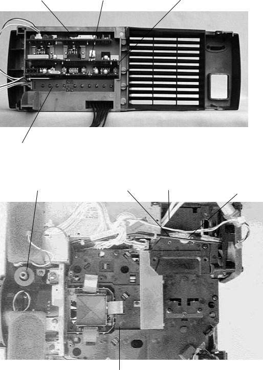
1.2.2 Inside View of Main Frame
Main board
Power supply unit
Figure1- 3 Inside view of main frame
REV.A
1-3

Driver board
Light guide unit
Figure1- 4 side view
LV Thermister |
Prism duct |
Driver board |
Exhaust fan |
Inlet unit
Figure1- 5 Under the main board view
REV.A
1-4
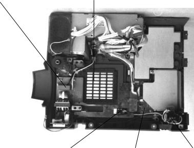
CD10AJ board |
CD10MJ board |
CD10RJ board |
CD10VJ board |
Figure1- 6 Inside of rear case unit |
Foot adjuster A |
Lamp Thermister Lamp power cable Safety switch |
Light guide unit
Figure1- 7 Under the driver board view
REV.A
1-5
Filter board |
Air filter frame |
Filter cover switch |
CN board |
Inlet unit |
Figure1- 8 Lower case view (Under the light guide block)
REV.A
1-6

1.2.3 Outside View of Remote Controller
Remote controller
Source button |
Menu button |
|
|
Effect button |
|
Pointer button |
Effect button |
|
|
|
Right click button |
Blank button |
|
|
Custom button |
Resize button |
Mute button |
|
|
Freeze button |
|
Power button |
Volume button |
|
|
Front view |
Rear view |
|
Left click button |
Remote infrared Ray |
|
|
Battery cover |
Figure111 Remote controller
REV.A
1-7
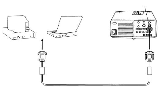
1.3 CONNECTION
1.3.1 Connecting to a PC
Computer 1
Computer cable (Attached Accessory )
Figure113
REV.A
1-8

1.3.2 Connecting to a Macintosh
Computer 1
Mac. Desk top adapter (Attached accessory)
Computer cable (Standard accessory)
Figure114
* Attached accessories
• ¦Dip switch settings are required according to the machine type.
Refer to the following table for detail. (Default setting is MAC13 mode.)
Table1- 1 MAC Adapter Dip Switch settings
Switch A |
Mode |
Switch A |
switch B |
|
“ON” |
“ON” |
|||
|
||||
Switch B |
VGA 640x480 |
3,4,5 |
8 |
|
13” 640x480 |
1,2,5 |
8 |
||
|
16” 832x624 |
2,4,5 |
8 |
|
MAC Adapter |
19” 1024x768 |
2,3,5 |
8 |
|
21” 1152x870 |
1,2,3,4,5 |
8 |
||
|
||||
|
13” Multi Res. |
1,2,5 |
8 |
|
|
14” Multi Res. |
1,2,5 |
3,4,8 |
|
|
17” Multi Res. |
1,2,5 |
3,8/4,8 |
|
|
21” Multi Res. |
1,2,5 |
3,8 |
Figure115 Monitor adapter
REV.A
1-9

1.3.3 Connecting to a Video source
Video |
Audio L |
Audio R |
A/V cable (Attached accessory)
Figure117 Connection for video source
1.3.4 Connecting to an Audio source
Audio out
External audio devices
Audio cable (Consumable)
Figure118 Connection for audio source
REV.A
1-10

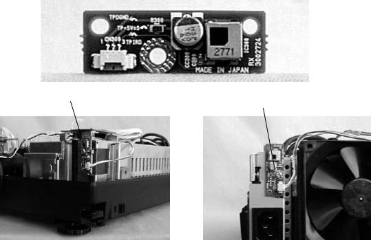
1.4 MAIN COMPORNENT
CD10MA board
Figure120 CD10MA board
CD10DR board
Figure122 CD10DR board
CD10AU board
Figure123 CD10AU board
REV.A
1-11
CD10MJ board
Figure126 CD10MJ board
CD10AJ board
Figure127 CD10AJ board
CD10PJ board
Figure128 CD10PJ board
CD10VJ board
Figure129 CD10VJ board
REV.A
1-12
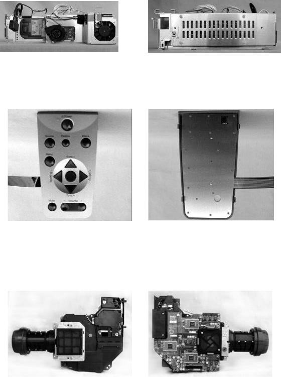
Power supply unit
Figure130 Switch panel
Switch panel
Figure131 Switch panel
(15) Optical engine
Figure132 Optical engine
REV.A
1-13
Receptor board
Receptor board |
Receptor board |
Figure133 Receptor board
REV.A
1-14

1.5 SPECIFICATIONS
Table1- 2 specifications
OPTICAL FEATURES
Display method |
Poly-silicon TFT (MLA built) color liquid crystal display |
|
(R/G/B three panels) |
|
Full lines, twelve phase block series |
Optical method |
Dichroic mirror separation and prism combine method |
Projection image size |
Minimum 30 inch to maximum 300 inch |
Projection distance |
1.2 m to 12 m |
Resolution |
1024 x768 dots, 2,359,296 pixels (786,432 x 3) |
Projection Lens |
Zoom lens F2.0 - 2.3 (55-72 mm) |
Focus adjustment |
Manual |
Zooming adjustment |
Manual(1:1.3) |
Light Source |
120 W (AC drive) |
Life(Lamp inner housing) |
UHE lamp,(type ELPLP05) |
|
2000 hours at 50% brightness |
Average iluminance |
Typical:950Lm(ANSI), Average:85% of typical |
AUDIO FEATURES |
|
Output for internal speaker |
Dynamic speaker(3W-8Ω) x 2 (stereo) |
Audio out Interface |
External speaker 3.5mm Stereo mini-jack |
|
Internal speaker output is stopped when mini-jack is |
|
plugged. |
|
Output signal:0 to 500mVrms |
|
load imperdance:600Ω |
Audio L/R interface |
Audio signal(stereo) from the video devices. Input interface |
(For Video device ) |
is separated with R(Right) and L(Left). |
|
Interface type:RCA jack |
|
Input signal:500mVrms |
Audio 1 interface |
Host computer 1 Audio input (stereo) |
(For Computer 1) |
Interface type:3.5mm Stereo mini-jack |
|
Input signal: 500mVrms/47KΩ |
|
|
Audio 2 interface |
Host computer 2 Audio input (stereo) |
(For Computer 2) |
Interface type:3.5mm Stereo mini-jack |
|
Input signal: 500mVrms/47KΩ |
|
|
REMOTE CONTROL |
|
Wireless remote controller |
For controlling EMP-7300 operating mode and controlling |
|
host computer from EMP-7300. |
|
Signal is detected with internal receptor board. |
|
Control range: Within 10 m and 30 degree wide (right/left), |
|
15 degree wide (upper/lower) from receptor of LCP. |
VIDEO INPUT/OUTPUT |
|
Computer 1 interface Computer 2 interface S-Video Interface
Host computer RGB output
Interface type: HD-15pin(DDC1/2B compatible)
Input signal: Luminous 0.714Vp-p,Chrominous 0.284Vp-p. Interface type: Min-DIN 4pin
S-Video is prior to composite video.
Video Interface
(Composite video interface)
Input signal: 0.7Vp-p, 75Ω sync: negative 0.3Vp-p Interface type: RCA jack
TV signal type: NTSC 3.58MHz AL 4.43MHz SECAM 4.43MHz
Auto identification(Default)
REV.A
1-15

MOUSE/COM 1/2 |
Auto identification (Mouse or RS-232C) |
|
|
Serial Mouse or RS-232C |
Interface type: DIN 13pin |
|
|
COMPONENT VIDEO INPUT |
|
(For EHQ option interface)
This interface is as RGB video terminal as well,then distinguish signal classification automatically.
Input signal: 0.7Vp-p, 75Ω input sync: negative 0.3Vp-p
the Interface type: BNC jack
Y :Commonjack as Video In G R-Y:Commonjack as Video In B B-Y:Commonjack as Video In R
POWER SUPPLY
Input Voltage |
AC100-120V /200-240V ±10% (50/60Hz) |
Power Consumption |
Approx. 260 W (Standby mode:30W) |
Dimensions |
300 mm (W) x 120 mm (H) x 363 mm (D) |
|
300 mm (W) x 129 mm (H) x 400 mm (D) |
|
include foot adjuster and lens. |
|
|
Weight |
Approx. 6.7 kg |
ENVIRONMENT |
|
Operational temperature |
+5 to +40 degrees centigrrate |
Storage temperature |
-10 to +60 degrees centigrrate (non condensing) |
Operational humidity/ Storage humidity |
20% to 80% / 10% to 90% (non condensing) |
Operational/storage Altitude |
3048m / 6096m |
REV.A
1-16
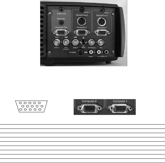
1.6 INTERFACE SPECIFICATION
Figure135
1.6.1 Computer 1/2
Computer video input D-SUB 15 (HD)
5 |
1 |
|
|
10 |
6 |
|
|
15 |
11 |
|
|
Pin |
Terminal |
Pin |
Terminal |
1 |
Red video |
9 |
+5V |
2 |
Green video |
10 |
Synchronous GND |
3 |
Blue video |
11 |
Monitor (ID bit 0) |
4 |
Monitor (ID bit 2) |
12 |
SDA |
5 |
GND |
13 |
Horizontal synchronization |
6 |
Red video GND |
14 |
Vertical synchronization |
7 |
Green video GND |
15 |
SCL |
8 |
Blue video GND |
|
|
REV.A
1-17
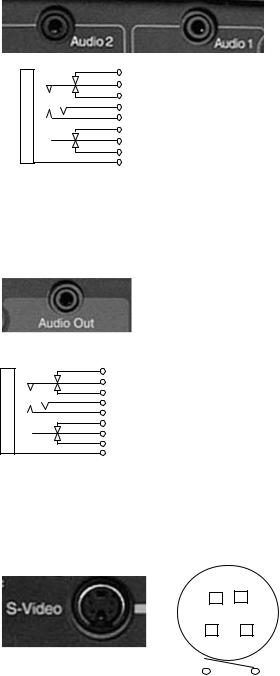
1.6.2 Audio 1/2
Stereo mini jack with 2 circuits for detection pin
(The detection pin which is not required for audio input, is equipped for audio out terminal.)
• |
H |
• |
H |
• |
H |
• |
H |
• |
H |
• |
H |
• |
H |
• |
H |
• |
H |
1 pin: GND
2 pin: Computer audio input L
3 pin: Computer audio input R The other pins: NC
1.6.3 Audio Out
Stereo mini jack with 2 circuits for detection pin
• |
H |
• |
H |
• |
H |
• |
H |
• |
H |
• |
H |
• |
H |
• |
H |
• |
H |
1,4 pin: GND
2 pin: Audio output L 3 pin: Audio output R 5 pin: Detection of Line-out jack insertion
The other pins: NC
1.6.4 S-Video
Mini DIN 4-pin with a detection pin
|
|
1,2,6 pin: GND |
4 |
3 |
3 pin: Y signal input |
4 pin: C signal input |
||
|
|
5 pin: Input detection terminal |
2 |
1 |
|
6 |
|
5 |
REV.A
1-18

1.6.5 Video
RCA Gold plating (only insertion part), |
Light angle H=15mm |
||||
Color: yellow |
|
|
|
||
|
|
|
2 |
1 pin: GND |
|
|
|
|
|||
|
|
|
|
|
2 pin: Video input |
|
|
|
|
1 |
|
1.6.6 Audio L/R |
|
|
|||
|
|
|
|||
RCA Gold plating(only insertion part), |
Light angle H=15mm |
||||
Color: L white R red |
|
|
|
||
3,6PIN |
3,6 pin: GND |
|
4 pin: Audio R return |
5 pin: Audio input L |
|
|
7 pin: Audio L return |
8 pin: Audio input R |
4,7PIN |
|
|
5,8PIN |
|
|
1.6.7 Mouse / Com 1/2
Multi-mouse jack 13-pin jack
Signal meanings are different according to the operation mode.
4 


 1
1
8 |
5 |
12 


 9
9
13
REV.A
1-19

Pin |
PS/2 |
98 |
Mac. |
Serial |
PC serial/ |
|
Mousel |
Mouse |
Mouse |
Mouse |
Mac.serial |
1 |
XA |
XA |
XA |
Reserved |
Reserved |
2 |
XB |
XB |
Reserved |
Reserved |
Reserved |
3 |
Reserved |
YA |
Reserved |
TXD |
Reserved |
4 |
Reserved |
YB |
Reserved |
READY |
Reserved |
5 |
LEFT |
LEFT |
Reserved |
GND |
Reserved |
6 |
Reserved |
RIGHT |
LEFT |
GND |
Reserved |
7 |
Reserved |
Reserved |
Reserved |
GND |
Reserved |
8 |
Reserved |
Reserved |
Reserved |
Reserved |
TXD |
9 |
Reserved |
Reserved |
Reserved |
Reserved |
RXD |
10 |
Reserved |
Reserved |
Reserved |
Reserved |
DTR |
11 |
Reserved |
Reserved |
Reserved |
Reserved |
DSR |
12 |
PCV(+5V) |
PCV(+5V) |
PCV(+5V) |
Reserved |
Reserved |
13 |
GND |
GND |
GND |
GND |
GND |
1.6.8 Receptor

 2
2
 1
1
PIN: GND
PIN1: GND PIN2: Serial Data
1.6.9 RGB Video Input (EHQ option I/F)
REV.A
1-20
Chapter 2
Theory of operation
 Loading...