

Page 1
BA01894F/00/EN/02.19
71440978
2019-06-28
Valid as of version
01.00.zz
Products Solutions Services
Operating Instructions
Liquiphant FTL51B
Vibronic
Limit switch for liquids
Page 2
Liquiphant FTL51B
Order code:
Ext. ord. cd.:
Ser. no.:
www.endress.com/deviceviewer
Endress+Hauser
Operations App
XXXXXXXXXXXX
XXXXX-XXXXXX
XXX.XXXX.XX
Serial number
1.
3.
2.
A0023555
2 Endress+Hauser
Page 3

Liquiphant FTL51B Table of contents
Table of contents
1 About this document ................ 5
1.1 Symbols ............................. 5
1.1.1 Safety symbols .................. 5
1.1.2 Electrical symbols ................ 5
1.1.3 Symbols for certain types of
information .................... 5
1.1.4 Symbols in graphics ............... 5
2 Basic safety instructions ............ 6
2.1 Requirements for the personnel ............ 6
2.2 Designated use ........................ 6
2.2.1 Incorrect use .................... 6
2.3 Workplace safety ....................... 6
2.4 Operational safety ...................... 6
2.5 Product safety ......................... 7
2.6 IT security ............................ 7
3 Product description ................. 7
3.1 Product design ........................ 8
4 Incoming acceptance and product
identification ....................... 9
4.1 Incoming acceptance .................... 9
4.2 Product identification .................... 9
4.2.1 Nameplate ..................... 9
4.2.2 Manufacturer address ............. 9
4.3 Storage and transport .................. 10
4.3.1 Storage conditions ............... 10
4.3.2 Transporting the device ........... 10
6.2 Connecting the measuring device .......... 17
6.2.1 2-wire AC (electronic insert
FEL61) ....................... 17
6.2.2 3-wire DC-PNP (electronic insert
FEL62) ....................... 19
6.2.3 Universal current connection with
relay output (electronic insert
FEL64) ....................... 21
6.2.4 DC connection, relay output
(electronic insert FEL64 DC) ....... 23
6.2.5 PFM output (electronic insert
FEL67) ....................... 25
6.2.6 2-wire NAMUR > 2.2 mA/< 1.0 mA
(electronic insert FEL68) .......... 27
6.2.7 Bluetooth module VU121
(optional) ..................... 29
6.2.8 LED module VU120 (optional) ...... 30
6.2.9 Cable entry .................... 30
6.3 Post-connection check .................. 31
7 Operation options ................. 32
7.1 Overview of operation options ............ 32
7.1.1 Operating concept .............. 32
7.1.2 Functional test using the button on
the electronic insert .............. 32
7.1.3 Functional test of the electronic
switch with a test magnet ......... 35
7.1.4 Heartbeat diagnostics and
verification with Bluetooth® wireless
technology .................... 36
7.2 LED module VU120 (optional) ............ 37
7.2.1 Configuration and sensor status ..... 37
5 Installation ....................... 11
5.1 Mounting conditions ................... 11
5.1.1 Taking the switch point into
consideration .................. 11
5.1.2 Take viscosity into consideration .... 12
5.1.3 Avoiding buildup ................ 13
5.1.4 Take clearance into consideration ... 13
5.1.5 Support the device ............... 14
5.1.6 Weld-in adapter with leakage hole .. 14
5.2 Mounting the measuring device ........... 14
5.2.1 Required tools .................. 14
5.2.2 Installation .................... 15
5.3 Sliding sleeves ....................... 16
5.4 Post-installation check .................. 16
6 Electrical connection .............. 17
6.1 Connection conditions .................. 17
6.1.1 Cover with securing screw ......... 17
6.1.2 Connecting protective earth (PE) .... 17
Endress+Hauser 3
8 Commissioning .................... 37
8.1 Function check ....................... 37
8.2 Switching on the measuring device ......... 38
8.3 Establishing a connection via SmartBlue
(app) .............................. 38
8.3.1 SmartBlue (app) ................ 38
9 Operation ......................... 40
9.1 Diagnostics menu ..................... 40
9.1.1 "Diagnostics" menu ............... 40
9.1.2 "Application" menu .............. 40
9.1.3 "System" menu .................. 41
9.2 Heartbeat Verification .................. 42
9.3 Recurrent testing for SIL/WHG (German
Water Resources Act) devices ............. 42
10 Diagnostics and troubleshooting ... 42
10.1 Diagnostic information via light emitting
diodes .............................. 43
10.1.1 LED at electronic insert ........... 43
Page 4

Table of contents Liquiphant FTL51B
10.1.2 SmartBlue ..................... 43
11 Maintenance ...................... 44
11.1 Maintenance tasks .................... 44
11.1.1 Cleaning ...................... 44
12 Repair ............................ 45
12.1 General information ................... 45
12.1.1 Repair concept ................. 45
12.1.2 Repair of Ex-certified devices ....... 45
12.2 Spare parts .......................... 45
12.3 Return .............................. 45
12.4 Disposal ............................ 46
13 Accessories ....................... 47
13.1 Device-specific accessories ............... 47
13.1.1 Test magnet ................... 47
13.1.2 Weather protection cover for dualcompartment housing, aluminum ... 47
13.1.3 Weather protection cover for single-
compartment housing, metal ....... 47
13.1.4 Plug-in jack .................... 48
13.1.5 Additional modules .............. 48
13.1.6 Sliding sleeves for unpressurized
operation ..................... 49
13.1.7 High pressure sliding sleeves ....... 50
14 Technical data .................... 52
14.1 Input ............................... 52
14.1.1 Measured variable .............. 52
14.1.2 Measuring range ............... 52
14.2 Output ............................. 52
14.2.1 Output and input variants ......... 52
14.2.2 Output signal .................. 53
14.2.3 Ex connection data .............. 53
14.3 Environment ......................... 53
14.3.1 Ambient temperature range ....... 53
14.3.2 Storage temperature ............. 54
14.3.3 Humidity ..................... 54
14.3.4 Operating altitude ............... 55
14.3.5 Climate class .................. 55
14.3.6 Degree of protection ............. 55
14.3.7 Vibration resistance ............. 55
14.3.8 Shock resistance ................ 55
14.3.9 Mechanical load ................ 56
14.3.10 Electromagnetic compatibility ...... 56
14.4 Process ............................. 56
14.4.1 Process temperature range ........ 56
14.4.2 Thermal shock ................. 56
14.4.3 Process pressure range ........... 56
14.4.4 Test pressure .................. 57
14.4.5 Density ...................... 57
14.4.6 Pressure tightness .............. 58
14.5 Additional technical data ................ 58
Index .................................. 59
4 Endress+Hauser
Page 5
Liquiphant FTL51B About this document
DANGER
WARNING
CAUTION
NOTICE
A
1.
-
.
1 About this document
1.1 Symbols
1.1.1 Safety symbols
This symbol alerts you to a dangerous situation. Failure to avoid this situation will result in
serious or fatal injury.
This symbol alerts you to a dangerous situation. Failure to avoid this situation can result in
serious or fatal injury.
This symbol alerts you to a dangerous situation. Failure to avoid this situation can result in
minor or medium injury.
This symbol contains information on procedures and other facts which do not result in
personal injury.
1.1.2 Electrical symbols
Ground connection
Grounded clamp, which is grounded via a grounding system.
Protective earth (PE)
Ground terminals, which must be grounded prior to establishing any other connections.
The ground terminals are located on the inside and outside of the device.
1.1.3 Symbols for certain types of information
Permitted
Procedures, processes or actions that are permitted.
Forbidden
Procedures, processes or actions that are forbidden.
Tip
Indicates additional information
Reference to documentation
Reference to another section
, 2., 3. Series of steps
1.1.4 Symbols in graphics
A, B, C ... View
1, 2, 3 ... Item numbers
Hazardous area
Safe area (non-hazardous area)
Endress+Hauser 5
Page 6

Basic safety instructions Liquiphant FTL51B
2 Basic safety instructions
2.1 Requirements for the personnel
The personnel must fulfill the following requirements to carry out the necessary tasks,
e. g., commissioning and maintenance:
Trained, qualified specialists must have a relevant qualification for the specific function
‣
and task
Are authorized by the plant owner/operator
‣
Are familiar with federal/national regulations
‣
Must have read and understood the instructions in the manual and supplementary
‣
documentation
Follow instructions and comply with conditions
‣
2.2 Designated use
• Only use the measuring device as a limit switch for liquids
• Improper use can pose hazards
• Ensure that the measuring device is free of defects while it is in operation
• Use the measuring device only for media to which the process-wetted materials have an
adequate level of resistance
• Do not exceed or drop below the limit values for the measuring device
TI01403F/00/EN
2.2.1 Incorrect use
The manufacturer is not liable for damage caused by improper or non-designated use.
Residual risks
Due to heat transfer from the process, the temperature of the electronics housing and the
assemblies contained therein may rise to 80 °C (176 °F) during operation.
Danger of burns from contact with surfaces!
If necessary, ensure protection against contact to prevent burns.
‣
For requirements concerning functional safety in accordance with IEC 61508, the
associated SIL documentation must be observed.
2.3 Workplace safety
For work on and with the device:
Wear the required protective equipment according to federal/national regulations.
‣
2.4 Operational safety
Risk of injury!
Operate the device only if it is in proper technical condition, free from errors and faults.
‣
The operator is responsible for ensuring failure-free operation of the device.
‣
Modifications to the device
Unauthorized modifications to the device are not permitted and can lead to unforeseeable
dangers.
If, despite this, modifications are required, consult with Endress+Hauser.
‣
6 Endress+Hauser
Page 7

Liquiphant FTL51B Product description
Repair
To ensure continued operational safety and reliability:
Only perform repair work on the device if this is expressly permitted.
‣
Observe federal/national regulations pertaining to the repair of an electrical device.
‣
Use original spare parts and accessories from Endress+Hauser only.
‣
2.5 Product safety
This measuring device is designed in accordance with good engineering practice to meet
state-of-the-art safety requirements, has been tested, and left the factory in a condition in
which it is safe to operate.
It meets general safety standards and legal requirements. It also complies with the EC
directives listed in the device-specific EC Declaration of Conformity. Endress+Hauser
confirms this by affixing the CE mark to the device.
2.6 IT security
We only provide a warranty if the device is installed and used as described in the
Operating Instructions. The device has safety mechanisms integrated to prevent users
from inadvertently changing settings.
Provide additional protection for the device and data transfer to/from the device
IT security measures defined in the plant owner/operator's own security policy must be
‣
implemented by plant owners/operators themselves.
3 Product description
Point level switch for minimum or maximum detection.
Endress+Hauser 7
Page 8
Product description Liquiphant FTL51B
1
2
3
4
5
Contains
FCC ID:
IC:
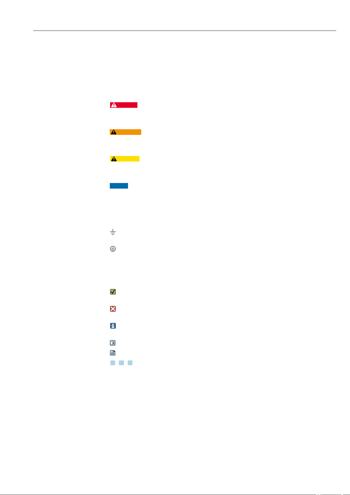
3.1 Product design
A0036953
1 Product design
1 Housing with electronic insert and cover, optional Bluetooth module or LED module
2 Optional spacer (temperature spacer or pressure-tight feedthrough (second line of defense))
3 Compact probe design
4 Probe design with pipe extension
5 Probe design with short pipe
Identify the electronic insert via the order code on the nameplate.
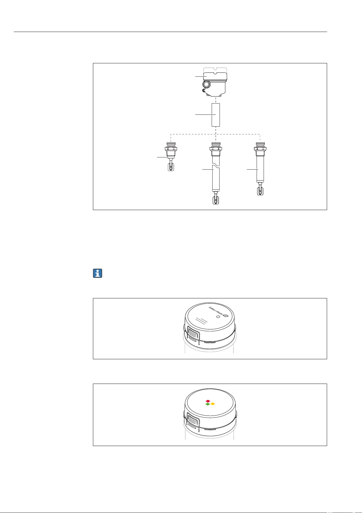
Optional: Bluetooth module VU121 or LED module VU120
A0039257
2 Bluetooth module
3 LED module
8 Endress+Hauser
A0039258
Page 9
Liquiphant FTL51B Incoming acceptance and product identification
Order code: Ser. no.:
Ext. ord. cd.:
L:
FW:
Dev.Rev.:
Pmax:
0.83 W PNP
2
3
5
1
4
4
4 Incoming acceptance and product
identification
4.1 Incoming acceptance
Check the following during goods acceptance:
Are the order codes on the delivery note and the product sticker identical?
Are the goods undamaged?
Do the nameplate data match the ordering information on the delivery note?
If required (see nameplate): Are the Safety Instructions, e. g. XA, provided?
Is the device properly secured?
If one of these conditions is not met, please contact the manufacturer's sales office.
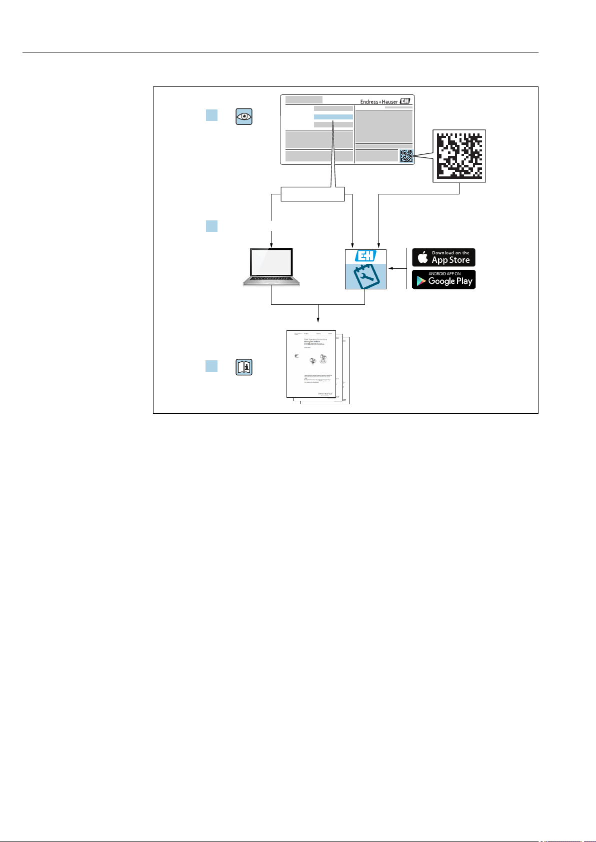
4.2 Product identification
The measuring device can be identified in the following ways:
• Nameplate data
• Extended order code with breakdown of the device features on the delivery note
• Enter serial number from nameplates in W@M Device Viewer
(www.endress.com/deviceviewer): All of the information on the measuring device is
displayed along with an overview of the scope of technical documentation provided
• Enter the serial number on the nameplate into the Endress+Hauser Operations App or
use the Endress+Hauser Operations App to scan the 2-D matrix code (QR Code) on the
nameplate
4.2.1 Nameplate
4 Nameplate specifications
1 Manufacturer name and device name
2 Manufacturer address
3 Order number, external order code, serial number
4 Technical data
5 Approval-specific information
4.2.2 Manufacturer address
Endress+Hauser SE+Co. KG
Hauptstraße 1
79689 Maulburg, Germany
Address of the manufacturing plant: See nameplate.
A0038187
Endress+Hauser 9
Page 10
Incoming acceptance and product identification Liquiphant FTL51B
4.3 Storage and transport
4.3.1 Storage conditions
Use original packaging.
Storage temperature
–40 to +80 °C (–40 to +176 °F)
optional: –52 °C (–62 °F), –60 °C (–76 °F)
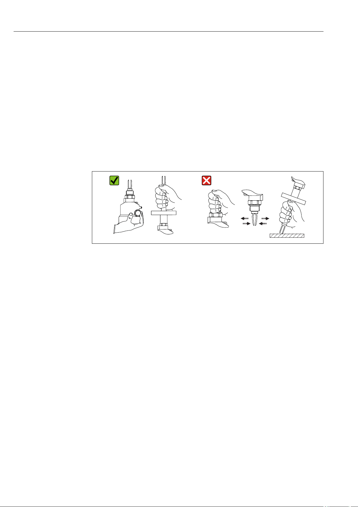
4.3.2 Transporting the device
• Transport the device to the measuring point in the original packaging
• Hold the device by the housing, temperature spacer, flange or extension pipe
• Do not bend, shorten or extend the tuning fork
5 Handling the device during transportation
A0034846
10 Endress+Hauser
Page 11
Liquiphant FTL51B Installation
1
~13 (0.5)
~4 (0.16)
~12.5 (0.49)
D
A B C
D
D
5 Installation
WARNING
L
Loss of protection rating if the device is opened in a wet environment.
Only open the device in a dry environment!
‣
A0037879
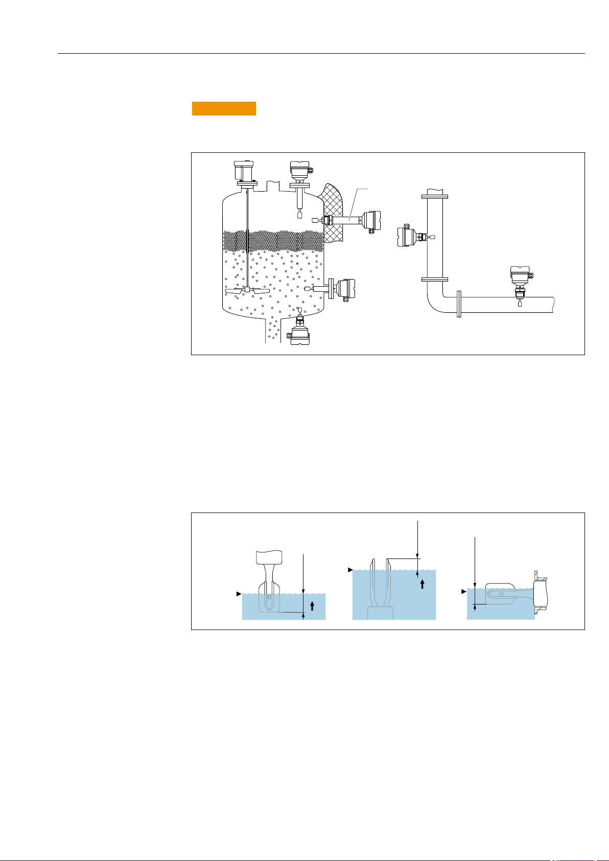
6 Installation in any position in a vessel, pipe or tank
1 Temperature spacer for tank with insulation and/or high process temperatures
5.1 Mounting conditions
5.1.1 Taking the switch point into consideration
Typical switch points, depending on the orientation of the point level switch
(water +23 °C (+73 °F))
A0037915
7 Typical switch points. Unit of measurement mm (in)
A Installation from above
B Installation from below
C Installation from the side
D Switch point
Endress+Hauser 11
Page 12
Installation Liquiphant FTL51B
> 25 (0.98)
D
> 40 (1.57)
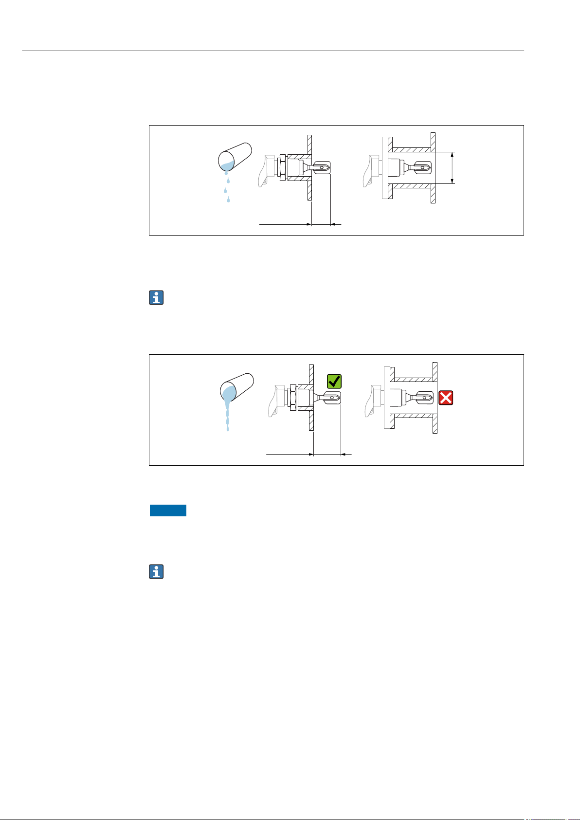
5.1.2 Take viscosity into consideration
Low viscosity
A0033297
8 Installation example for low-viscosity liquids. Unit of measurement mm (in)
D Diameter of installation socket: at least 50 mm (2.0 in)
Low viscosity, e. g. water: < 2 000 mPa⋅s
It is permitted to position the tuning fork within the installation socket.
High viscosity
9 Installation example for a highly viscous liquid. Unit of measurement mm (in)
NOTICE
Highly viscous liquids may cause switching delays.
Make sure that the liquid can run off the tuning fork easily.
‣
Deburr the socket surface.
‣
High viscosity, e. g. viscous oils: < 10 000 mPa⋅s
The tuning fork must be located outside the installation socket!
A0037348
12 Endress+Hauser
Page 13
Liquiphant FTL51B Installation
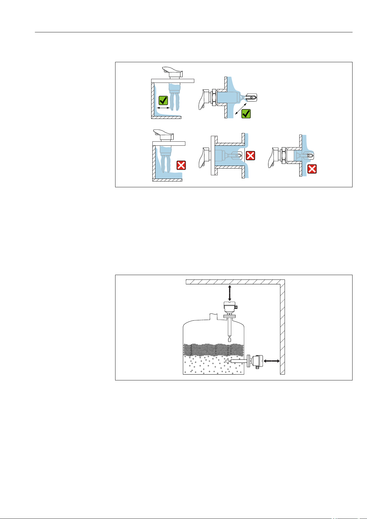
5.1.3 Avoiding buildup
A0033239
10 Installation examples for a highly viscous process medium
• Use short installation sockets to ensure that the turning fork can project freely into the
vessel.
• Install preferably flush-mounted on vessels or in pipes.
• Leave sufficient distance between the buildup expected on the tank wall and the tuning
fork.
5.1.4 Take clearance into consideration
A0033236
11 Take clearance into consideration
Allow sufficient space outside the tank for mounting, connection and settings involving
the electronic insert.
Endress+Hauser 13
Page 14
Installation Liquiphant FTL51B
316L
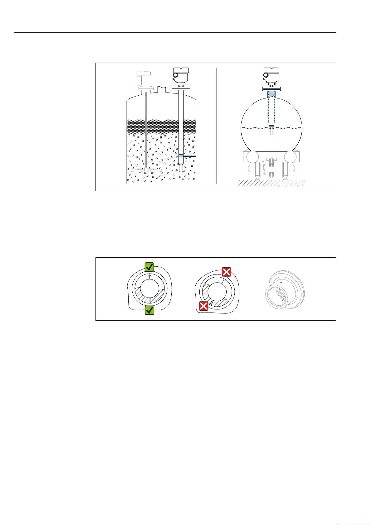
5.1.5 Support the device
A0031874
12 Support in the event of dynamic load
Support the device in the event of severe dynamic load. Maximum lateral loading capacity
of the pipe extensions and sensors: 75 Nm (55 lbf ft).
5.1.6 Weld-in adapter with leakage hole
A0039230
13 Weld-in adapter with leakage hole
Weld in the welding neck in such a way that the leakage hole is pointing downwards. This
enables any leaks to be detected quickly.
5.2 Mounting the measuring device
5.2.1 Required tools
• Open-ended wrench for sensor installation
• Screwdriver for electrical connection
14 Endress+Hauser
Page 15
Liquiphant FTL51B Installation
316L/G1
5.2.2 Installation
Horizontal installation in vessels
Align the tuning fork with the marking
A0039125
14 Marking to align the tuning fork
Use the marking to align the tuning fork in such a way that medium can run off easily and
deposit buildup is avoided.
The following can be used as the marking:
• Material specification, thread description or circle on the hexagonal nut or on the weldin adapter
• The II symbol on the back of the flange or Tri-Clamp
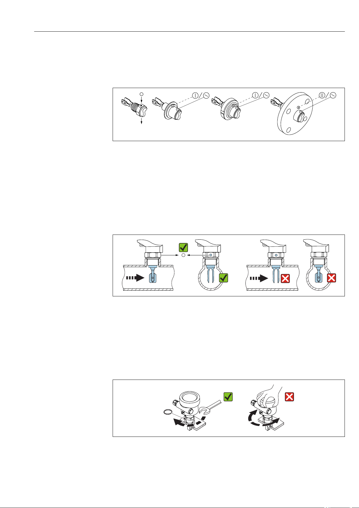
Installing in pipes
15 Marking and fork position
• Flow velocity up to 5 m/s with viscosity 1 mm2/s (cSt) and density 1 g/cm3 (SGU)
Check for correct functioning in the event of other process medium conditions
• The marking on the adapter points in the flow direction; the flow is thus not severely
obstructed
• The marking can be identified while the device is installed
Screwing in the device
A0034851
A0034852
16 Screwing in the device
• Turn by the hex bolt only, 15 to 30 Nm (11 to 22 lbf ft)
• Do not turn at the housing!
Endress+Hauser 15
Page 16
Installation Liquiphant FTL51B
1.
2.
3
0.7 Nm
3
3.
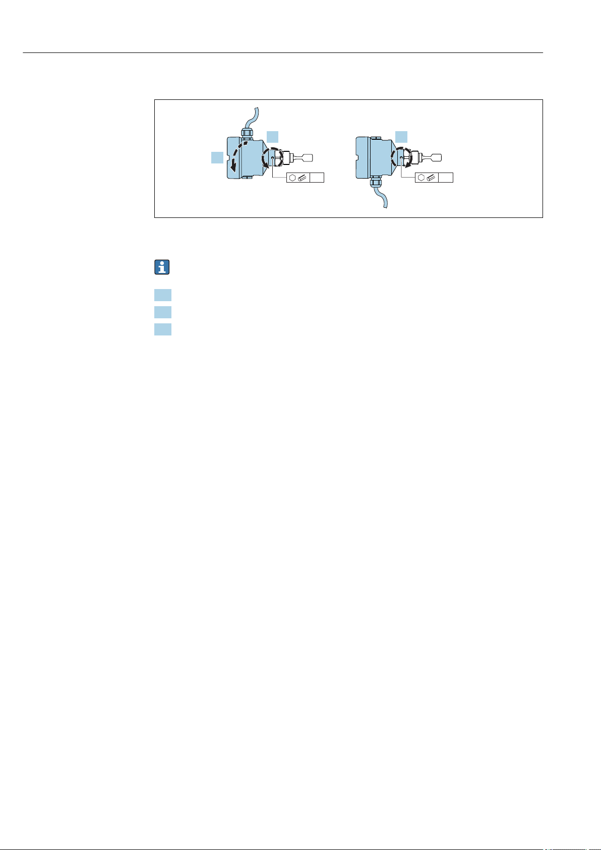
Aligning the cable entry
A0037347
17 Housing with external locking screw
The locking screw is not tightened when the device is delivered.
1. Release the external locking screw.
2. Turn the housing, align the cable entry.
3. Tighten the external locking screw.
5.3 Sliding sleeves
See the "Accessories" section.
5.4 Post-installation check
Is the measuring device undamaged (visual inspection)?
Does the measuring device conform to the measuring point specifications?
For example:
• Process temperature
• Process pressure
• Ambient temperature range
• Measuring range
Are the measuring point number and labeling correct (visual inspection)?
Is the measuring device adequately protected against precipitation and direct sunlight?
Is the device properly secured?
16 Endress+Hauser
Page 17
Liquiphant FTL51B Electrical connection
6 Electrical connection
6.1 Connection conditions
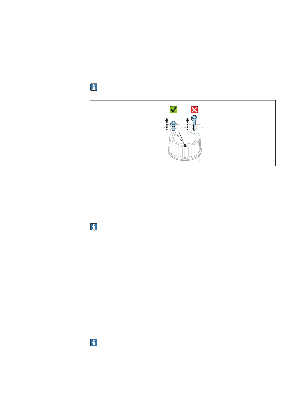
6.1.1 Cover with securing screw
Covers with a securing screw are available for devices for use in hazardous areas. Do
not release the screw fully.
A0039520
18 Cover with securing screw
6.1.2 Connecting protective earth (PE)
The protective earth conductor at the device must only be connected if the device's
operating voltage is ≥ 35 VDC or ≥ 16 VACeff.
When the device is used in hazardous areas, it must always be included in the potential
equalization of the system, irrespective of the operating voltage.
The plastic housing is available with or without an external protective earth
connection (PE).
6.2 Connecting the measuring device
6.2.1 2-wire AC (electronic insert FEL61)
• Two-wire AC version
• Switches the load directly into the power supply circuit via an electronic switch; always
connect in series with a load.
• Functional testing without level change
A functional test can be performed on the device using the test button on the electronic
insert.
Supply voltage
U = 19 to 253 V
Residual voltage when switched through: maximum 12 V
Pay attention to the following as per IEC/EN61010-1: Provide a suitable circuit
breaker for the device, and limit the current to 1 A, e. g. by installing a 1 A fuse (slowblow) in the line (not the neutral wire) of the supply circuit.
Power consumption
P ≤ 2 VA
Endress+Hauser 17
AC
Page 18
Electrical connection Liquiphant FTL51B
!
>0,5
COM
NL1
1
2
MIN
MAX
>0,7
U 19...253 V AC
I max: 350 mA
~
~
1 A
L1 NPE
K
1 2
Current consumption
Residual current when blocked: I ≤ 3.8 mA
The red LED flashes in the event of an overload or short-circuit. Check for an overload or
short-circuit every 5 seconds. The test is deactivated after 60 seconds.
Power output and load current
• Max 89 VA/253 V (350 mA); max 8.4 VA/24 V (350 mA)
• Min 2.5 VA/253 V (10 mA); min ≥ 0.5 VA/24 V (20 mA)
• With overload and short-circuit protection.
Behavior of output signal
• OK status: load on (switched through)
• Demand mode: load off (blocked)
• Alarm: load off (blocked)
Terminal assignment
Always connect an external load. The electronic insert has integrated short-circuit
protection.
A0036060
19 2-wire AC, electronic insert FEL61
18 Endress+Hauser
Page 19

Liquiphant FTL51B Electrical connection
MAX
RD YE GN
MIN
K
K
K
K
K
(N)
(N)
(N)
(N)
(N)
I
L
I
L
<3.8 mA
<3.8 mA
<3.8 mA
2
2
2
2
2
1
1
1
1
1
L1
L1
L1
L1
L1
ΔU
ΔU
Behavior of switch output and signaling
A0031901
20 Behavior of switch output and signaling, electronic insert FEL61
MAXDIP switch for setting MAX safety mode
MIN DIP switch for setting MIN safety mode
RD LED, red, for warning or alarm
YE LED, yellow, switch status
GN LED, green, operational status, device on
ILLoad current switched through
6.2.2 3-wire DC-PNP (electronic insert FEL62)
• Three-wire DC version
• Preferably in conjunction with programmable logic controllers (PLC), DI modules as per
EN 61131-2. Positive signal at switch output of electronics module (PNP)
• Functional testing without level change
A functional test can be performed on the device using the test button on the electronic
insert or using the test magnet with the housing closed.
Supply voltage
WARNING
L
Failure to use the prescribed power unit.
Risk of fatal injury due to electric shock!
The FEL62 may only be powered by devices with safe galvanic isolation, as per
‣
IEC 61010-1.
U =10 to 55 V
Pay attention to the following as per IEC/EN61010-1: Provide a suitable circuit
breaker for the device, and limit the current to 500 mA, e. g. by installing a 0.5 A fuse
(slow-blow) in the line (not the neutral wire) of the supply circuit.
Power consumption
P ≤ 0.5 W
DC
Current consumption
I ≤ 10 mA (without load)
The red LED flashes in the event of an overload or short-circuit.
Endress+Hauser 19
Page 20

Electrical connection Liquiphant FTL51B
!
U = 10...55 V DC
I max: 350 mA
1
3
L-L+
COM
MIN
MAX
>0,7
>0,5
1
3
0.5 A
L+ L-
I 350 mA
max
U 55 V
max
K
K
I
L
PE
4
3
1
2
1
3
4
M12
1 2 3
B
A
L+ L-
K
Load current
I ≤ 350 mA with overload and short-circuit protection
Capacitance load
C ≤ 0.5 µF at 55 V, C ≤ 1.0 µF at 24 V
Residual current
I < 100 µA (with transistor blocked)
Residual voltage
U < 3 V (with transistor switched through)
Behavior of output signal
• OK status: switched through
• Demand mode: blocked
• Alarm: blocked
Terminal assignment
21 3-wire DC-PNP, electronic insert FEL62
A Connection wiring with terminals
B Connection wiring with M12 connector in housing as per EN61131-2 standard
20 Endress+Hauser
A0036061
Page 21

Liquiphant FTL51B Electrical connection
MAX
RD YE GN
MIN
K
K
K
(L–)
(L–)
(L–)
I
L
<100 µA
I
L
3
3
3
1
1
1
L+
L+
L+
ΔU
ΔU
K
(L–)
<100 µA
3
1
L+
(L–)
<100 µA
3
1
L+
K
Behavior of switch output and signaling
A0033508
22 Behavior of switch output and signaling, electronic insert FEL62
MAXDIP switch for setting MAX safety mode
MIN DIP switch for setting MIN safety mode
RD LED, red, for warning or alarm
YE LED, yellow, switch status
GN LED, green, operational status, device on
ILLoad current switched through
6.2.3 Universal current connection with relay output (electronic
insert FEL64)
• Switches the loads via 2 potential-free changeover contacts
• Two galvanically isolated change-over contacts (DPDT), both change-over contacts
switch simultaneously
• Functional testing without level change. A functional test can be performed on the
device using the test button on the electronic insert or using the test magnet with the
housing closed.
WARNING
L
In the event of an error, the electronic insert can exceed the limit temperature for
touchable surfaces, resulting in a risk of burns.
Do not touch the electronics in the event of an error!
‣
Supply voltage
U = 19 to 253 VAC/19 to 55 V
Pay attention to the following as per IEC/EN61010-1: Provide a suitable circuit
breaker for the device, and limit the current to 500 mA, e. g. by installing a 0.5 A fuse
(slow-blow) in the line (not the neutral wire) of the supply circuit.
Power consumption
P < 25 VA,< 1.3 W
DC
Connectable load
Loads switched via 2 potential-free changeover contacts (DPDT)
• IAC ≤ 6 A (Ex de 4 A), U~ ≤ AC 253 V; P~ ≤ 1 500 VA, cos φ = 1, P~ ≤ 750 VA, cos φ > 0.7
• IDC ≤ 6 A (Ex de 4 A) to DC 30 V, I DC ≤ 0.2 A to 125 V
Endress+Hauser 21
Page 22

Electrical connection Liquiphant FTL51B
L1 N
4
3 5
876
U = 19...55 V DC
U 19...253 V AC
~
~
!
0.5 A
1
2 2
L1
L+
NO NONC NCC CNL-PE
1 2 3 64 75 8
MIN
>0,7
MAX
>0,5
COM
According to IEC 61010: the sum of the voltages of the relay outputs and power supply
≤ 300 V
Preferably use electronic insert FEL62 DC PNP for low DC current loads, e. g. connection to
a PLC.
Relay contact material: silver/nickel AgNi 90/10
When connecting a device with high inductance, fit a spark suppressor to protect the relay
contact. Depending on the connected load, a fine-wire fuse protects the relay contact in
the event of a short-circuit.
Both relay contacts switch simultaneously.
Behavior of output signal
• OK status: relay energized
• Demand mode: relay de-energized
• Alarm: relay de-energized
Terminal assignment
23 Universal current connection with relay output, electronic insert FEL64
1 When bridged, the relay output works using NPN logic.
2 Connectable load
22 Endress+Hauser
A0036062
Page 23

Liquiphant FTL51B Electrical connection
3 54
3 54
6 87
6 87
3 54
33554
4
6 87
66887
7
MAX
RD YE GN
MIN
Behavior of switch output and signaling
A0033513
24 Behavior of switch output and signaling, electronic insert FEL64
MAXDIP switch for setting MAX safety mode
MIN DIP switch for setting MIN safety mode
RD LED, red, for alarm
YE LED, yellow, switch status
GN LED, green, operational status, device on
6.2.4 DC connection, relay output (electronic insert FEL64 DC)
• Switches the loads via 2 potential-free changeover contacts
• Two galvanically isolated change-over contacts (DPDT), both change-over contacts
switch simultaneously
• Functional testing without level change. Functional testing of the entire device can be
performed using the test button on the electronic insert or with the test magnet with the
housing closed.
Supply voltage
U = 9 to 20 V
Pay attention to the following as per IEC/EN61010-1: Provide a suitable circuit
breaker for the device, and limit the current to 500 mA, e. g. by installing a 0.5 A fuse
(slow-blow) in the power circuit.
Power consumption
P < 1.0 W
Connectable load
Loads switched via 2 potential-free changeover contacts (DPDT)
• IAC ≤ 6 A (Ex de 4 A), U~ ≤ AC 253 V; P~ ≤ 1 500 VA, cos φ = 1, P~ ≤ 750 VA, cos φ > 0.7
• IDC ≤ 6 A (Ex de 4 A) to DC 30 V, I DC ≤ 0.2 A to 125 V
According to IEC 61010: the sum of the voltages of the relay outputs and power supply
≤ 300 V
Preferably use electronic insert FEL62 DC PNP for low DC current loads, e. g. connection to
a PLC.
Relay contact material: silver/nickel AgNi 90/10
DC
Endress+Hauser 23
Page 24

Electrical connection Liquiphant FTL51B
L1 N
4
3 5
876
U = 9...20 V DC
!
0.5 A
1
2 2
L1
L+
NO NONC NCC CNL-PE
1 2 3 64 75 8
MIN
>0,7
MAX
>0,5
COM
When connecting a device with high inductance, fit a spark suppressor to protect the relay
contact. Depending on the connected load, a fine-wire fuse protects the relay contact in
the event of a short-circuit.
Behavior of output signal
• OK status: relay energized
• Demand mode: relay de-energized
• Alarm: relay de-energized
Terminal assignment
A0037685
25 DC connection with relay output, electronic insert FEL64 DC
1 When bridged, the relay output works using NPN logic.
2 Connectable load
24 Endress+Hauser
Page 25

Liquiphant FTL51B Electrical connection
3 54
3 54
6 87
6 87
3 54
33554
4
6 87
66887
7
MAX
RD YE GN
MIN
Behavior of switch output and signaling
A0033513
26 Behavior of switch output and signaling, electronic insert FEL64 DC
MAXDIP switch for setting MAX safety mode
MIN DIP switch for setting MIN safety mode
RD LED, red, for alarm
YE LED, yellow, switch status
GN LED, green, operational status, device on
6.2.5 PFM output (electronic insert FEL67)
• For connecting to the Nivotester FTL325P and FTL375P switching units from Endress
+Hauser
• PFM signal transmission; pulse frequency modulation, superimposed on the power
supply along the two-wire cabling
• Functional testing without level change:
• A functional test can be performed on the device using the test button on the
electronic insert.
• The functional test can also be prompted by disconnecting the supply voltage or
triggered directly by the Nivotester FTL325P and FTL375P switching unit.
Supply voltage
U = 9.5 to 12.5 V
Pay attention to the following as per IEC/EN61010-1: Provide a suitable circuit
breaker for the device.
Power consumption
P ≤ 150 mW with Nivotester FTL325P or FTL375P
Behavior of output signal
• OK status: MAX mode 150 Hz, MIN mode 50 Hz
• Demand mode: MAX mode 50 Hz, MIN mode 150 Hz
• Alarm: MAX/MIN mode 0 Hz
DC
Endress+Hauser 25
Page 26

Electrical connection Liquiphant FTL51B
>0,5
COM
MIN
MAX
>0,7
– +
1
2
L- L+
!
!
7
33
37
d4
z4
8
34
38
d2
z2
z6 d6
.
-
1 2
Terminal assignment
A0036065
27 PFM output, electronic insert FEL67
7/ 8: Nivotester FTL325P 1 CH, FTL325P 3 CH input 1
33/ 34: Nivotester FTL325P 3 CH input 2
37/ 38: NivotesterFTL325P 3 CH input 3
d4/ d2: Nivotester FTL375P input 1
z4/ z2: Nivotester FTL375P input 2
z6/ d6: Nivotester FTL375P input 3
Connection cable
• Maximum cable resistance: 25 Ω per core
• Maximum cable capacitance: < 100 nF
• Maximum cable length: 1 000 m (3 281 ft)
26 Endress+Hauser
Page 27

Liquiphant FTL51B Electrical connection
MAX
RD YE GN
MIN
1
1
1
1
1
2
2
2
2
2
L+
L+
L+
L+
L+
150 Hz
50 Hz
50 Hz
150 Hz
0 Hz
L-
L-
L-
L-
L-
Behavior of switch output and signaling
A0037696
28 Switching behaviour and signaling, electronic insert FEL67
MAXDIP switch for setting MAX safety mode
MIN DIP switch for setting MIN safety mode
RD LED, red, for alarm
YE LED, yellow, switch status
GN LED, green, operational status, device on
The MAX/MIN switch must be set in accordance with the application. Only then is it
possible to perform the functional test correctly.
6.2.6 2-wire NAMUR > 2.2 mA/< 1.0 mA (electronic insert FEL68)
• For connecting to isolating amplifier as per NAMUR (IEC 60947-5-6), e. g. the
Nivotester FTL325N from Endress+Hauser
• Signal transmission H-L edge 2.2 to 3.8 mA/ 0.4 to 3.8 mA as per IEC 60947-5-6
(NAMUR) on two-wire cable
• Functional testing without level change. A functional test can be performed on the
device using the test button on the electronic insert or using the test magnet with the
housing closed.
The functional test can also be triggered by interrupting the supply voltage or activated
directly from the Nivotester FTL325N.
Supply voltage
U = 8.2 V
Power consumption
NAMUR IEC 60947-5-6
Behavior of output signal
• OK status: output current 2.2 to 3.8 mA
• Demand mode: output current 0.4 to 1.0 mA
• Alarm: output current 0.4 to 1.0 mA
DC
Pay attention to the following as per IEC/EN61010-1: Provide a suitable circuit
breaker for the device.
Endress+Hauser 27
Page 28

Electrical connection Liquiphant FTL51B
>0,5
COM
– +
MIN
MAX
>0,7
IEC 60947-5-6
8,2 V DC NAMUR
1
2
L- L+
.
-
1 2
!
!
MAX
RD YE GN
MIN
1
1
1
1
1
2
2
2
2
2
L+
L+
L+
L+
L+
2.2...3.8 mA
0.4...1.0 mA
2.2...3.8 mA
0.4...1.0 mA
< 1.0 mA
L-
L-
L-
L-
L-
Terminal assignment
A0036066
29 2-wire NAMUR > 2.2 mA/< 1.0 mA, electronic insert FEL68
Behavior of switch output and signaling
30 Behavior of switch output and signaling, electronic insert FEL68
MAXDIP switch for setting MAX safety mode
MIN DIP switch for setting MIN safety mode
RD LED, red, for alarm
YE LED, yellow, switch status
GN LED, green, operational status, device on
A0037694
When using the device with the electronic insert FEL68 (2-wire NAMUR), the
Bluetooth module must be ordered separately, including the required battery.
Product Configurator, order code for "Accessory mounted", option NG "Prepared for
Heartbeat Verification + Monitoring + Bluetooth".
28 Endress+Hauser
Page 29

Liquiphant FTL51B Electrical connection
Contains
FCC ID:
IC:
1.
2.
6.2.7 Bluetooth module VU121 (optional)
A0039257
31 Bluetooth module VU121
• The Bluetooth module can be connected via the COM interface to the following
electronic inserts: FEL61, FEL62, FEL64, FEL64 DC, FEL67, FEL68 (2-wire NAMUR).
• The Bluetooth module with battery is suitable for use in hazardous areas.
• For energy-related reasons, the Bluetooth module requires a special battery when
operated with the 2-wire NAMUR electronics.
When using the device with the electronic insert FEL68 (2-wire NAMUR), the
Bluetooth module must be ordered separately, including the required battery.
Product Configurator, order code for "Accessory mounted", option NG "Prepared for
Heartbeat Verification + Monitoring + Bluetooth".
Batteries
The battery is categorized as dangerous goods when transported by air and may not
be installed in the device when shipped.
Replacement batteries can be purchased from a specialist retailer. Only the following
types of AA 3.6 V lithium batteries made by the manufacturers listed below are
suitable as replacement batteries:
• SAFT LS14500
• TADIRAN SL-360/s
• XENOENERGY XL-060F
Connecting the module
A0039242
32 Connecting the module
Connect the Bluetooth module with the COM interface in the electronic insert.
Endress+Hauser 29
Page 30

Electrical connection Liquiphant FTL51B
6.2.8 LED module VU120 (optional)
A0039258
33 LED module
The bright LED display indicates the switch status or the alarm condition and can be
connected to the following electronic inserts: FEL62, FEL64, FEL64DC
Supply voltage
U = 12 to 55 VDC, 19 to 253 V
AC
Power consumption
U ≤ 0.7 W, < 6 VA
Current consumption
I
= 0.4 A
max
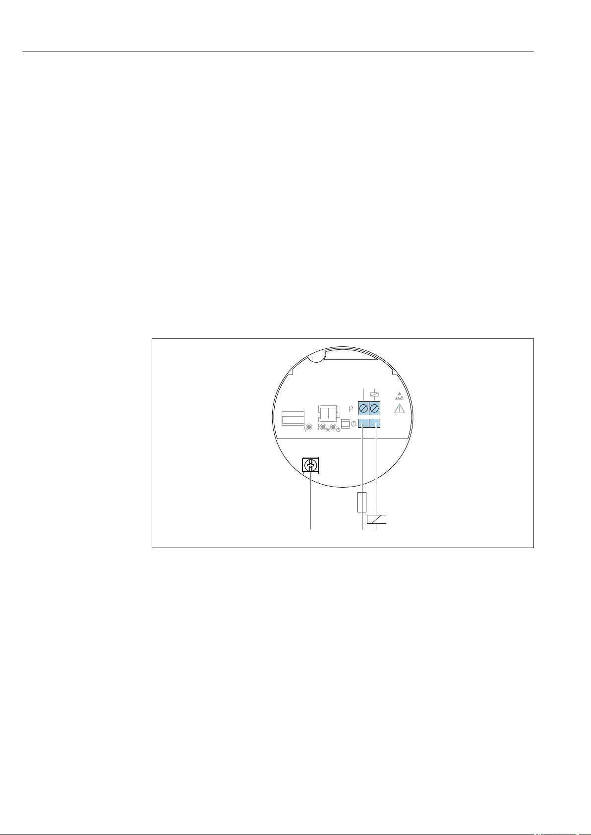
Connecting the module
34 Connecting the LED module
A0033542
1. Attach the connecting cable of the LED module to the connecting cables of the supply
voltage. Use the wire end ferrules supplied.
2. Connect the wire end ferrules to the terminals of the measuring device.
3. Connect the LED module with the COM interface in the electronic insert.
6.2.9 Cable entry
Required tools
• Flat-blade screwdriver (0.6 x 3.5 mm) for terminals
• Torque spanner (8 Nm) for M20 cable gland
30 Endress+Hauser
Page 31

Liquiphant FTL51B Electrical connection
1
2
3
!
ød
3.5
A0018023
35 Cable entry, electronic insert
1 M20 cable gland
2
Conductor cross-section, 2.5 mm2 maximum (AWG14)
3
Conductor cross-section, 4.0 mm2 maximum (AWG12)
ød Nickel-plated brass 7 to 10.5 mm (0.28 to 0.41 in)
ød Plastic 5 to 10 mm (0.2 to 0.38 in)
ød Stainless steel 7 to 12 mm (0.28 to 0.47 in)
Secure the cable gland and tighten the union nut of the cable gland, 8 Nm (5.9 lbf ft)
torque. Screw the enclosed cable glands into the housing with a torque of
3.75 Nm (2.76 lbf ft).
6.3 Post-connection check
Is the device or cable undamaged (visual inspection)?
Do the cables used comply with the requirements?
Do the mounted cables have adequate strain relief?
Are the cable glands mounted and firmly tightened?
Does the supply voltage match the specifications on the nameplate?
No reverse polarity, is terminal assignment correct?
If supply voltage is present, is the green LED lit?
Are all the housing covers installed and tightened?
Optional: Is the cover with securing screw tightened?
Endress+Hauser 31
Page 32

Operation options Liquiphant FTL51B
>0,5
COM
NL1
1
2
MIN
MAX
>0,7
>0,5
1
2
MIN
MAX
>0,7
7 Operation options
7.1 Overview of operation options
7.1.1 Operating concept
• Operation with button and DIP switches on the electronic insert
• Display with optional Bluetooth module and SmartBlue (app) via Bluetooth® wireless
technology
• Indication of switching status and operational status with optional LED module (lights
visible from the outside)
• For plastic housing and aluminum housing (standard and Ex d) in conjunction with the
DC-PNP and relay electronics
• Ordering information: Product Configurator, order code for "Display; operation" option
"B"
7.1.2 Functional test using the button on the electronic insert
A0037132
36 Position of button for functional test
The functional test must be performed when the device status is OK.
Status OK: MAX safety and sensor free or MIN safety and sensor covered.
• Press the test button for at least 1 second (FEL61/62/64/64DC/67/68 electronic
inserts)
• The output changes to the safety-oriented state - the functional test of the device takes
place
• Test duration at least 10 s or until the button is released if the button is pressed for
> 10 s
• The device returns to normal operation if the internal test is successful
The LEDs flash one after another as a chaser light during the functional test.
If the housing cannot be opened during operation due to explosion protection
requirements, e. g., EX d/XP), the functional test can also be performed from the outside
using the test magnet (FEL62, FEL64 DC, FEL68). The functional test of the PFM
electronics (FEL67) and NAMUR electronics (FEL68) can be started at the Nivotester
FTL325P/N.
Pay attention to the information in the Safety Manual for proof testing safety
equipment in accordance with SIL or WHG (German Water Resources Act).
1. Make sure no undesired switching processes are triggered!
2. Press the button "T" on the electronic insert for at least 1 s (e. g., with a screwdriver).
The output changes from the OK status to demand mode.
32 Endress+Hauser
Page 33

Liquiphant FTL51B Operation options
YE YE
GNRD GN
RD
1.
2.
>1 s
3.
MAX
MIN
K
(N)
<3.8 mA
2
1
L
K
(N)
<3.8 mA
2
1
L
K
(N)
2
1
L
ΔU
I
L
K
(N)
<3.8 mA
2
1
L
K
(N)
<3.8 mA
2
1
L
K
(N)
A
2
1
L
YE YE
GNRD GN
RD
1.
2.
>1 s
3.
MAX
MIN
K
(L-)
<100 µA
3
1
L+
K
(L-)
3
1
L+
ΔU
I
L
K
(L-)
A
3
1
L+
K
(L-)
3
1
L+
<100 µA
K
(L-)
3
1
L+
<100 µA
K
(L-)
3
1
L+
<100 µA
FEL61 switching behavior and signaling
A0039210
37 FEL61 switching behavior and signaling
A After the test button is pressed, the load is switched off for at least 10 seconds (I < 3.8 mA) even if the button
is pressed for < 10 seconds. If the button is pressed for > 10 seconds, the load remains switched off
(I < 3.8 mA) until the test button is released. The load is then switched on again.
FEL62 switching behaviour and signaling
A0039211
38 FEL62 switching behaviour and signaling
A After the test button is pressed, the DC-PNP output is switched off for at least 10 seconds (I < 100 µA) even if
the button is pressed for < 10 seconds. If the button is pressed for > 10 seconds, the DC-PNP output remains
switched off ((I < 100 µA) until the test button is released. The DC-PNP output is then switched on again.
Endress+Hauser 33
Page 34

Operation options Liquiphant FTL51B
1.
2.
>1 s
3.
MAX
MIN
YE
GNRD
YE
GN
RD
3
4
5
678
3
4
5
678
3
4
5
678
3
4
5
678
3
4
5
678
3
4
5
678
A
1.
2.
>1 s
3.
MAX
YE
GNRD
YE
GN
RD
150 Hz
1
2
L+ L-
50 Hz
1
2
L+
L-
50 Hz
1
2
L+
L-
50 Hz
1
2
L+
L-
50 Hz
1
2
L+ L-
A
1
2
L+ L-
FEL64, FEL64DC switching behavior and signaling
A0039212
39 FEL64, FEL64DC switching behavior and signaling
A After the test button is pressed, the relay is de-energized for at least 10 seconds even if the button is pressed
for < 10 seconds. If the test button is pressed for > 10 seconds, the relay remains de-energized until the test
button is released. The relay is then energized again.
FEL67 switching behaviour and signaling
A distinction must be made between MAX and MIN operating modes in the case of
the FEL67 electronic insert!
A0039213
40 FEL67 MAX switching behaviour and signaling
A After the test button is pressed, the output frequency is switched off for at least 10 seconds, 50 Hz, even if the
button is pressed for < 10 seconds. If the button is pressed for > 10 seconds, the output frequency remains at
50 Hz until the test button is released. The output frequency then returns to 150 Hz once again.
34 Endress+Hauser
Page 35

Liquiphant FTL51B Operation options
1.
2.
>1 s
3.
YE
GNRD
YE
GN
RD
50 Hz
1
2
L+ L-
150 Hz
1
2
L+
L-
150 Hz
1
2
L+
L-
150 Hz
1
2
L+
L-
150 Hz
1
2
L+ L-
A
1
2
L+ L-
MIN
YE YE
GNRD GN
RD
1.
2.
>1 s
3.
MAX
MIN
2.2 ... 3.5 mA 0.6 ... 1 mA
0.6 ... 1 mA
0.6 ... 1 mA
A
0.4 … 1 mA
1 1
1 1
1 1
2
2
2
L+
L+
L+
2
2
2
L+
L+
L+
A0039214
41 FEL67 MIN switching behaviour and signaling
A After the test button is pressed, the output frequency is switched off for at least 10 seconds, 150 Hz, even if
the button is pressed for < 10 seconds. If the button is pressed for > 10 seconds, the output frequency remains
at 150 Hz until the test button is released. The output frequency then returns to 50 Hz once again.
The PFM frequency cannot be measured on site. It is therefore recommended to proof
test the functionality at the Nivotester FTL325P/FTL375P.
FEL68 switching behaviour and signaling
A0033543
42 NAMUR electronics switching behaviour and signaling
A After the test button is pressed, the current is 0.6 to 1 mA for at least 10 seconds even if the button is pressed
for < 10 seconds. If the button is pressed for > 10 seconds, the current remains at 0.6 to 1 mA until the test
button is released. The current then returns to 2.2 to 3.5 mA.
7.1.3 Functional test of the electronic switch with a test magnet
Perform functional test of the electronic switch without opening the device
• Hold the test magnet against the marking on the nameplate on the outside
• Simulation is possible in the case of the FEL62, FEL64, FEL64DC, FEL68 electronic
inserts
The functional test with the test magnet acts in the same way as pressing the test button
on the electronic insert.
Endress+Hauser 35
Page 36

Operation options Liquiphant FTL51B
Ser. no.:
Order code:
Ext. ord. cd.:
1
2
A0033419
43 Functional test with test magnet
7.1.4 Heartbeat diagnostics and verification with Bluetooth® wireless technology
Access via Bluetooth® wireless technology
A0033411
44 Remote operation via Bluetooth® wireless technology
1 Smartphone or tablet with SmartBlue (app)
2 Device with optional Bluetooth module
Bluetooth module VU121 (optional)
Functions
• Connection via COM interface: Bluetooth module for device diagnostics via a smartphone
app or tablet app
• Display the battery status via app when used with electronic insert FEL68 (NAMUR)
• User guidance (wizard) for SIL/WHG proof testing
• Visible in the livelist 10 seconds after the Bluetooth search commences
• Data can be read from the Bluetooth module 60 seconds after the supply voltage is
switched on
• Display of the current vibration frequency and the switching state of the device
The yellow LED flashes when the Bluetooth module is connected to another Bluetooth
device, e. g. mobile phone.
Heartbeat Technology
Heartbeat Technology module
Heartbeat Diagnostics
Continuously monitors and evaluates the device status and process conditions. Generates
diagnostic messages when certain events occur and provides troubleshooting measures in
accordance with NAMUR NE 107.
Heartbeat Verification
Performs a verification of the current device status upon request and generates a
Heartbeat Technology verification report showing the result of the verification.
Heartbeat Monitoring
Continuously provides device and/or process data for an external system. Analysis of this
data forms the basis for process optimization and predictive maintenance.
36 Endress+Hauser
Page 37

Liquiphant FTL51B Commissioning
Technical data
• Approval: intrinsically safe Ex ia, IS or ec/ic
• NAMUR electronics (electronic insert FEL68):
For energy-related reasons, the Bluetooth module VU121 requires a special battery
when operated with the 2-wire NAMUR electronics. The service life of the Bluetooth
module without replacing the battery is at least 5 years with a maximum of 60
downloads of complete datasets (at ambient temperatures between
10 to 40 °C (50 to 104 °F)).
• Maximum free-field range 50 m (165 ft)
• Operation radius with intervisibility 10 m (33 ft) around the device
For documentation on radio approvals, see the Endress+Hauser website:
www.endress.com → Downloads.
7.2 LED module VU120 (optional)
The LED module lights up very brightly and can be easily identified from a distance. It can
be connected to the following electronic inserts: FEL62, FEL64, FEL64 DC
Depending on either the MAX/MIN setting, the sensor status can be identified from the
LEDs; displayed in the colors green, yellow and red.
The three colors of the LEDs flash one after another as a chaser light during the functional
test.
7.2.1 Configuration and sensor status
LED shows a green light
• MAX, sensor status: Not covered
• MIN, sensor status: Covered
LED shows a yellow light
• MAX, sensor status: Covered
• MIN, sensor status: Not covered
LED shows a red light
Alarm
LED flashes red
• Warning
• FEL62 overload/short-circuit or no communication
The three colors of the LEDs flash one after another as a chaser light during the functional
test.
8 Commissioning
8.1 Function check
Before commissioning the measuring point, check whether the post-installation and postconnection checks have been performed:
• "Post-installation check" checklist → 16
• "Post-connection check" checklist → 31
Endress+Hauser 37
Page 38

Commissioning Liquiphant FTL51B
ID:
_____________
_________
____________
XXX-XXXXXX
8.2 Switching on the measuring device
During the power-up time, the device output is in the safe state, or in the alarm state if
available.
FEL61, FEL62, FEL64, FEL64DC electronic inserts: The output is in the correct state for a
maximum of 3 seconds after the device is switched on.
NAMUR FEL68 and PFM FEL67 electronic inserts: A functional test is always carried out
when the device is switched on. The output is in the correct state after a maximum of 10
seconds.
8.3 Establishing a connection via SmartBlue (app)
8.3.1 SmartBlue (app)
Requirements
Device requirements
Commissioning via SmartBlue is only possible if a Bluetooth module is installed in the
device.
System requirements
SmartBlue is available as a download from the Google Play Store for Android devices and
from the iTunes Store for iOS devices
• iOS devices: iPhone 4S or higher from iOS9.0; iPad2 or higher from iOS9.0; iPod Touch
5th generation or higher from iOS9.0
• Devices with Android: from Android 4.4 KitKat and Bluetooth® 4.0
Initial password
The ID number (serial number) on the nameplate of the Bluetooth module is used as the
initial password when establishing the connection for the first time.
It is important to note the following if the Bluetooth module is removed from one
device and installed in another device: all log-in data are only stored in the Bluetooth
module and not in the device. This also applies to the password changed by the user.
Preparatory steps
Note down the ID number of the Bluetooth module. The ID number on the nameplate of
the Bluetooth module is used as the initial password when establishing the connection for
the first time.
The high cover with the window must be used for devices that are operated with the
Bluetooth module.
A0039040
38 Endress+Hauser
Page 39

Liquiphant FTL51B Commissioning
Establishing a connection via SmartBlue (app)
1. Scan the QR code or enter "SmartBlue" in the search field.
A0039186
45 Download link
2. Start SmartBlue.
3. Select device from livelist displayed.
4. Log-in:
User name: admin
Password: ID number on the Bluetooth module
5. Tap the icons for more information.
After logging in for the first time, change the password!
Saving PDF reports
The PDF reports generated in the SmartBlue app are not automatically saved and
must therefore be actively saved on the smartphone or tablet.
Endress+Hauser 39
Page 40

Operation Liquiphant FTL51B
9 Operation
9.1 Diagnostics menu
The following data can be read out via the optional Bluetooth module and the associated
Endress+Hauser SmartBlue app.
9.1.1 "Diagnostics" menu
Diagnostics
Actual diagnostics
‣
Actual diagnostics
Timestamp
Event logbook
‣
Diagnostics 1
Timestamp
Diagnostics 2
Timestamp
Diagnostics 3
Timestamp
Diagnostics 4
Timestamp
Diagnostics 5
Timestamp
9.1.2 "Application" menu
Application
Operating mode
‣
MIN/MAX setting
Density setting
40 Endress+Hauser
Page 41

Liquiphant FTL51B Operation
Switching delay uncovered to covered
Switching delay covered to uncovered
Output
‣
Digital Output-Status
9.1.3 "System" menu
System
Electronic type
Bluetooth configuration
‣
BLE HW revision
Information
‣
Device tag
Serial number
Firmware version
Device name
Order code
Manufacturer
Manufacturer ID
ENP version
Operating time
Number of system starts
Time stamp of last proof test
Date of last proof test
Frequency at delivery status
Current frequency
Endress+Hauser 41
Page 42

Diagnostics and troubleshooting Liquiphant FTL51B
Upper alarm frequency
Upper warning frequency
Lower alarm frequency
Battery status
Temperature
Min. electronics temperature
Max. electronics temperature
9.2 Heartbeat Verification
The "Heartbeat Verification" module contains the Heartbeat Verification wizard which
carries out the verification of the current device status and creates the Heartbeat
Technology verification report:
• The wizard can be used via the SmartBlue app.
• The wizard takes the user through the entire process of creating the verification report.
• Displays the operating hours counter and the temperature drag indicator.
• If the vibration frequency of the fork increases, a corrosion warning appears.
• The order configuration of the air's vibration frequency is shown on the verification
report. An increased vibration frequency indicates corrosion. A reduced vibration
frequency signals deposits or that the medium is covering the sensor. Deviations
between the current vibration frequency and the vibration frequency upon delivery can
be caused by the process temperature and process pressure.
9.3 Recurrent testing for SIL/WHG (German Water
Resources Act) devices
The "SIL Prooftest", "WHG Prooftest" and "SIL/WHG Prooftest" modules contain a wizard for
recurrent testing. This is required at appropriate intervals for the following applications:
SIL (IEC61508/IEC61511), WHG (German Water Resources Act):
• The wizard can be used via the SmartBlue app.
• The wizard takes the user through the entire process of creating the verification report.
• The verification report can be saved as a PDF file.
10 Diagnostics and troubleshooting
The device indicates warnings and faults via Bluetooth in the SmartBlue app and via the
LEDs on the electronic insert. All the device warnings and faults are for information
purposes only and do not have a safety function. The faults diagnosed by the device are
displayed in the SmartBlue app in accordance with NE107. Depending on the diagnostic
message, the device behaves as per a warning or fault condition.
The device behaves in accordance with NAMUR Recommendation NE131 "NAMUR
standard device requirements for field devices for standard applications".
1) Only available for devices with SIL or WHG approval
1)
42 Endress+Hauser
Page 43

Liquiphant FTL51B Diagnostics and troubleshooting
If using NAMUR electronics, change or insert the battery in the Bluetooth module.
10.1 Diagnostic information via light emitting diodes
10.1.1 LED at electronic insert
LED green not lit
Possible cause: No power supply
Troubleshooting: Check plug, cable and power supply
LED flashes red
Possible cause: Overload or short-circuit in load circuit
Troubleshooting: Clear the short-circuit
Reduce maximum load current to below 350 mA
LED red continuously lit
Possible cause: Internal sensor error or electronic fault
Troubleshooting: Replace device
10.1.2 SmartBlue
Device is not visible in the live list
Possible cause: No Bluetooth connection available
The device is already connected to another smartphone or tablet
No cable is connected to the Bluetooth module
Troubleshooting:
• Connect the Bluetooth module to the COM interface
• Enable Bluetooth function on smartphone or tablet
• If using NAMUR electronics, change or insert the battery in the Bluetooth module
Device is visible in the live list but cannot be accessed via SmartBlue
• Possible cause on Android end device
Troubleshooting:
• Check whether the location function is enabled for the app
• Check whether the location function for the app was approved the first time
• GPS or positioning function must be activated for certain Android versions in
conjunction with Bluetooth®
• Activate GPS, close the app fully and restart, enable the positioning function for the
app
• Possible cause on Apple end device
Troubleshooting:
• Log in as normal
• Enter the user name: admin
• Enter initial password (serial number of Bluetooth module), paying attention to lower/
upper case
Login via SmartBlue not possible
Possible cause: Device is being put into operation for the first time
Troubleshooting: Enter initial password (ID number of Bluetooth module) and change it,
paying attention to lower/upper case.
No communication with device via SmartBlue
• Possible cause: Incorrect password entered
Troubleshooting: Enter correct password
• Possible cause: Forgotten password
Troubleshooting: Contact Endress+Hauser Service
Endress+Hauser 43
Page 44

Maintenance Liquiphant FTL51B
11 Maintenance
No special maintenance work is required.
11.1 Maintenance tasks
11.1.1 Cleaning
It is not permitted to use the device with abrasive media. Material abrasion on the tuning
fork can result in the device malfunctioning.
• Clean the tuning fork as necessary
• Cleaning is also possible in the installed state, e. g. CIP Cleaning in Place and SIP
Sterilization in Place
44 Endress+Hauser
Page 45

Liquiphant FTL51B Repair
12 Repair
12.1 General information
12.1.1 Repair concept
Endress+Hauser repair concept
• Measuring devices have a modular design
• Customers can carry out repairs
For more information on service and spare parts, please contact your Endress+Hauser
sales representative.
12.1.2 Repair of Ex-certified devices
WARNING
L
Limitation of electrical safety due to incorrect connection!
Risk of explosion!
Only specialist personnel or the Endress+Hauser service team may carry out repairs on
‣
Ex-certified devices.
Relevant standards and national regulations on hazardous areas, safety instructions
‣
and certificates must be observed.
Use only original Endress+Hauser spare parts.
‣
Please note the device designation on the nameplate. Only identical parts may be used
‣
as replacements.
Carry out repairs according to the instructions. On completion of repair work, carry out
‣
the routine test specified for the device.
Only the Endress+Hauser service team is permitted to modify a certified device and
‣
convert it to another certified version.
All repairs and modifications must be documented.
‣
12.2 Spare parts
• Some replaceable measuring device components are identified by means of a spare part
nameplate. This contains information about the spare part.
• All the spare parts for the measuring device along with the order code are listed in the
W@M Device Viewer (www.endress.com/deviceviewer) and can be ordered. If available,
users can also download the associated Installation Instructions.
Measuring device serial number or QR code:
Located on the device and spare part nameplate.
12.3 Return
The measuring device must be returned if the wrong device has been ordered or delivered.
As an ISO-certified company and also due to legal regulations, Endress+Hauser is obliged
to follow certain procedures when handling any returned products that have been in
contact with medium. To ensure safe, swift and professional device returns, please refer to
the procedure and conditions for returning devices provided on the Endress+Hauser
website at http://www.endress.com/support/return-material
Endress+Hauser 45
Page 46

Repair Liquiphant FTL51B
12.4 Disposal
If required by the Directive 2012/19/EU on waste electrical and electronic equipment
(WEEE), our products are marked with the depicted symbol in order to minimize the
disposal of WEEE as unsorted municipal waste. Such products may not be disposed of as
unsorted municipal waste and can be returned to Endress+Hauser for disposal at
conditions stipulated in our General Terms and Conditions or as individually agreed.
46 Endress+Hauser
Page 47

Liquiphant FTL51B Accessories
81 (3.19)
103 (4.06)
102.5 (4.04)
73.5 (2.89)
135 (5.31)
229.4 (9.03)
136.7 (5.38)
Ø
65 (2.56)
140 (5.51) 32 (1.26)
115 (4.53)
122 (4.8)
13 Accessories
13.1 Device-specific accessories
13.1.1 Test magnet
Order number: 71437508
A0039209
46 Test magnet
13.1.2 Weather protection cover for dual-compartment housing,
aluminum
• Material: stainless steel 316L
• Order number: 71438303
47 Weather protection cover for dual-compartment housing, aluminum. Unit of measurement mm (in)
13.1.3 Weather protection cover for single-compartment housing,
metal
• Material: plastic
• Order number: 71438291
A0039231
A0038280
48 Weather protection cover for single-compartment housing, metal. Unit of measurement mm (in)
Endress+Hauser 47
Page 48

Accessories Liquiphant FTL51B
27.5
(1.08)
40³
(1.57)
27.5
(1.08)
40³
(1.57)
13.1.4 Plug-in jack
The plug-in jacks listed are suitable for use in the temperature range
–25 to +70 °C (–13 to +158 °F).
Plug-in jack M12 IP69
• Terminated at one end
• Elbowed 90°
• 5 m (16 ft) PVC cable (orange)
• Slotted nut 316L (1.4435)
• Body: PVC (orange)
• Order number: 52024216
49 Plug-in jack M12 IP69. Unit of measurement mm (in)
Plug-in jack M12 IP67
• Elbowed 90°
• 5 m (16 ft)PVC cable (gray)
• Slotted nut Cu Sn/Ni
• Body: PUR (blue)
• Order number: 52010285
50 Plug-in jack M12 IP67. Unit of measurement mm (in)
13.1.5 Additional modules
A0023713
A0022292
If the Liquiphant is retrofitted with the Bluetooth module or the LED module, it is also
necessary to order a tall housing cover with sight glass. The cover depends on the
housing and approval of the device.
More detailed information is available:
• Product Configurator on the Endress+Hauser webpage: www.endress.com
• Endress+Hauser Sales Center www.addresses.endress.com
48 Endress+Hauser
Page 49

Liquiphant FTL51B Accessories
Contains
FCC ID:
IC:
Bluetooth module VU121 (optional)
A0039257
51 Bluetooth module VU121
The Bluetooth module can be connected to the following electronic inserts via the COM
interface: FEL61, FEL62, FEL64, FEL64DC, FEL67, FEL68 (NAMUR 2-wire).
• Bluetooth module with battery for use in conjunction with NAMUR electronics FEL68
electronic insert
Order number: 71437381
• Bluetooth module without battery for use in conjunction with FEL61, FEL62, FEL64,
FEL64DC and FEL67 electronic inserts
Order number: 71437383
When using the device with the electronic insert FEL68 (2-wire NAMUR), the
Bluetooth module must be ordered separately, including the required battery.
Product Configurator, order code for "Accessory mounted", option NG "Prepared for
Heartbeat Verification + Monitoring + Bluetooth".
LED module VU120 (optional)
52 LED module
The bright LED display indicates the switch status or the alarm condition and can be
connected to the following electronic inserts: FEL62, FEL64, FEL64DC
Order number: 71437382
13.1.6 Sliding sleeves for unpressurized operation
Switch point, infinitely adjustable.
A0039258
Endress+Hauser 49
Page 50

Accessories Liquiphant FTL51B
22 (0.87)
18 (0.71)
G 1 A
(1 NPT)
G 1½ A
(1½ NPT)
M6 (3x)
1
M6 (3x)
19 (0.75)
19 (0.75)
55
55
A0037666
53 Sliding sleeves for unpressurized operation. Unit of measurement mm (in)
1 pe = 0 bar (0 psi)
G 1, DIN ISO 228/I
• Material: 1.4435 (AISI 316L)
• Weight: 0.21 kg (0.46 lb)
• Order number: 52003978
• Order number: 52011888, approval: with inspection certificate EN 10204 - 3.1 material
NPT 1, ASME B 1.20.1
• Material: 1.4435 (AISI 316L)
• Weight: 0.21 kg (0.46 lb)
• Order number: 52003979
• Order number: 52011889, approval: with inspection certificate EN 10204 - 3.1 material
G 1½, DIN ISO 228/I
• Material: 1.4435 (AISI 316L)
• Weight: 0.54 kg (1.19 lb)
• Order number: 52003980
• Order number: 52011890, approval: with inspection certificate EN 10204 - 3.1 material
NPT 1½, ASME B 1.20.1
• Material: 1.4435 (AISI 316L)
• Weight: 0.54 kg (1.19 lb)
• Order number: 52003981
• Order number: 52011891, approval: with inspection certificate EN 10204 - 3.1 material
13.1.7 High pressure sliding sleeves
• Switch point, infinitely adjustable
• For use in hazardous areas,
• Seal package made of graphite
• For G 1, G 1½: seal included in delivery
50 Endress+Hauser
Page 51

G 1 A
(1 NPT)
G 1½A
(1½ NPT)
ø60 (2.36)
~72 (2.83)
~70 76(2. )
2 (0.08)
2 (0.08)
ø60 (2.36)
18 71(0. )
5050
Liquiphant FTL51B Accessories
54 High pressure sliding sleeves. Unit of measurement mm (in)
G 1, DIN ISO 228/I
• Material: 1.4435 (AISI 316L)
• Weight: 1.13 kg (2.49 lb)
• Order number: 52003663
• Order number: 52011880, approval: with inspection certificate EN 10204 - 3.1 material
G 1, DIN ISO 228/I
• Material: AlloyC22
• Weight: 1.13 kg (2.49 lb)
• Approval: with inspection certificate EN 10204 - 3.1 material
• Order number: 71118691
NPT 1, ASME B 1.20.1
• Material: 1.4435 (AISI 316L)
• Weight: 1.13 kg (2.49 lb)
• Order number: 52003667
• Order number: 52011881, approval: with inspection certificate EN 10204 - 3.1 material
NPT 1, ASME B 1.20.1
• Material: AlloyC22
• Weight: 1.13 kg (2.49 lb)
• Approval: with inspection certificate EN 10204 - 3.1 material
• Order number: 71118694
G 1½, DIN ISO 228/1
• Material: 1.4435 (AISI 316L)
• Weight: 1.32 kg (2.91 lb)
• Order number: 52003665
• Order number: 52011882, approval: with inspection certificate EN 10204 - 3.1 material
G 1½, DIN ISO 228/1
• Material: AlloyC22
• Weight: 1.32 kg (2.91 lb)
• Approval: with inspection certificate EN 10204 - 3.1 material
NPT 1½, ASME B 1.20.1
• Material: 1.4435 (AISI 316L)
• Weight: 1.32 kg (2.91 lb)
• Order number: 52003669
• Order number: 52011883, approval: with inspection certificate EN 10204 - 3.1 material
NPT 1½, ASME B 1.20.1
• Material: AlloyC22
• Weight: 1.32 kg (2.91 lb)
• Approval: with inspection certificate EN 10204 - 3.1 material
• Order number: 71118695
A0037667
Endress+Hauser 51
Page 52

Technical data Liquiphant FTL51B
14 Technical data
14.1 Input
14.1.1 Measured variable
Level (point level), MAX or MIN safety
14.1.2 Measuring range
Depends on the installation location and the pipe extension ordered
Maximum sensor length 6 m (20 ft)
14.2 Output
14.2.1 Output and input variants
Electronic inserts
2-wire AC (FEL61)
• Two-wire AC version
• Switches the load directly into the power supply circuit via an electronic switch.
3-wire DC-PNP (FEL62)
• Three-wire DC version
• Switches the load via the transistor (PNP) and separate connection, e. g. in conjunction
with programmable logical controllers (PLC)
• Ambient temperature –60 °C (–76 °F), optionally available for order
Low-temperature electronic inserts are marked LT.
Universal current connection, relay output (FEL64)
• Switches the loads via 2 potential-free changeover contacts
• Ambient temperature –60 °C (–76 °F), optionally available for order
Low-temperature electronic inserts are marked LT.
Direct current connection, relay output (FEL64DC)
• Switches the load via 2 potential-free changeover contacts
• Ambient temperature –60 °C (–76 °F), optionally available for order
Low-temperature electronic inserts are marked LT.
PFM output (FEL67)
• For separate switching device (Nivotester FTL325P, FTL375P)
• PFM signal transmission; current pulses are superimposed on the power supply along
the two-wire cabling
• Ambient temperature –52 °C (–62 °F), optionally available for order
The low-temperature electronic inserts are marked LT
2-wire NAMUR > 2.2 mA/< 1.0 mA (FEL68)
• For separate switching device, e. g. Nivotester FTL325N
• Signal transmission H-L edge 2.2 to 3.8/0.4 to 1.0 mA as per IEC 60917-5-6 (NAMUR)
on two-wire cable
• Ambient temperature –52 °C (–62 °F), optionally available for order
Low-temperature electronic inserts are marked LT.
2-wire density (FEL60D) for density measurement
Connection to Density Computer FML621
For more information, see the Technical Information for density measuring
technology.
52 Endress+Hauser
Page 53

Liquiphant FTL51B Technical data
14.2.2 Output signal
Switch output
Preset switching times can be ordered. The following ranges can be ordered for point level
switches without communication (AC two-wire, relays, DC-PNP, PFM, NAMUR):
• 0.5 seconds when the fork is covered and 1.0 seconds when it is uncovered (factory
setting)
• 0.25 seconds when the fork is covered and 0.25 seconds when it is uncovered (fastest
setting)
• 1.5 seconds when the fork is covered and 1.5 seconds when it is uncovered
• 5 seconds when the fork is covered and 5 seconds when it is uncovered
COM interface
For connecting to modules VU120 or VU121 (no modifying effect)
Bluetooth® wireless technology (optional)
The device has a Bluetooth® wireless technology interface. Device data and diagnostic data
can be read out using the free "SmartBlue" app.
14.2.3 Ex connection data
See safety instructions (XA): All data relating to explosion protection are provided in
separate Ex documentation and are available from the Downloads Area of the
Endress+Hauser-website. The Ex documentation is supplied as standard with all Ex
devices.
14.3 Environment
14.3.1 Ambient temperature range
–40 to +70 °C (–40 to +158 °F)
WARNING
L
Permitted connection voltage exceeded!
For electrical safety reasons, the maximum connection voltage for all electronic inserts
‣
at ambient temperatures below –40 °C (–40 °F) is limited to a maximum of 35 V DC.
Optional
–60 °C (–76 °F) or –52 °C (–62 °F)
In the hazardous area, the permitted ambient temperature can be limited depending on
the zones and gas groups. Pay attention to the information in the Ex documentation (XA).
The minimum permitted ambient temperature of the plastic housing is limited to
–20 °C (–4 °F); "indoor use" applies in North America.
Endress+Hauser 53
Page 54

Technical data Liquiphant FTL51B
T
p
+150
+302
+120
+248
+90
+194
+60
+140
+30
+86
0
32
-30
-22
-60
-76
70158
60140
50122
40104
3086
20
68
1050
032
A
B
[°C]
[°C]
[°F]
[°F]
T
a
A0037923
55 Permitted ambient temperature Ta at the housing as a function of the process temperature Tp in the vessel:
A Device without LED module; at process temperature Tp > 90°, with FEL64 and max. load current 4 A
B Device with LED module; at process temperature and FEL64 Tp > 90° max. load current 2 A
For devices with a temperature spacer, the following ambient temperatures apply across
the entire process temperature range:
A: 70 °C
B: 60 °C
Ordering information:
• Product Configurator, order code for "output", option "1"
Ambient temperature –60 °C (–76 °F), optionally available for order
• Product Configurator, order code for "output", option "2"
Ambient temperature –52 °C (–62 °F), optionally available for order.
Low-temperature electronic inserts are marked LT.
• Bluetooth module (non-Ex): –40 to +85 °C (–40 to +185 °F)
• Bluetooth module (Ex ia): –40 to +65 °C (–40 to +149 °F), T4
• LED module: –40 to +60 °C (–40 to +140 °F)
Outdoor operation in strong sunlight:
• Mount the device in the shade.
• Avoid direct sunlight, particularly in warmer climatic regions.
• Use a weather protection cover, which can be ordered as an accessory
14.3.2 Storage temperature
–40 to +80 °C (–40 to +176 °F)
optional: –52 °C (–62 °F), –60 °C (–76 °F)
14.3.3 Humidity
54 Endress+Hauser
Operate up to 100 %. Do not open in a condensing atmosphere.
Page 55

Liquiphant FTL51B Technical data
14.3.4 Operating altitude
As per IEC 61010-1 Ed.3:
• Up to 2 000 m (6 600 ft) above sea level
• Can be extended to 3 000 m (9 800 ft) above sea level if overvoltage protection is used
14.3.5 Climate class
As per IEC 60068-2-38 test Z/AD
14.3.6 Degree of protection
For housing with electrical connection
M20 coupling, plastic
• Single-chamber, plastic: IP66/67 NEMA type 4X
• Single-chamber and dual-chamber, aluminum: IP66/68 NEMA type 4X/6P
• Single-chamber 316L, cast: IP66/68 NEMA type 4X/6P
M20 coupling, nickel-plated brass
Single-chamber and dual-chamber, aluminum: IP66/68 NEMA type 4X/6P
M20 coupling, 316L
• Single-chamber and dual-chamber, aluminum: IP66/68 NEMA type 4X/6P
• Single-chamber 316L, cast: IP66/68 NEMA type 4X/6P
Thread M20
• Single-chamber, plastic: IP66/67 NEMA type 4X
• Single-chamber and dual-chamber, aluminum: IP66/68 NEMA type 4X/6P
• Single-chamber 316L, cast: IP66/68 NEMA type 4X/6P
Thread G ½
• Single-chamber, plastic: IP66/67 NEMA type 4X
• Single-chamber and dual-chamber, aluminum: IP66/68 NEMA type 4X/6P
• Single-chamber 316L, cast: IP66/68 NEMA type 4X/6P
Thread NPT ½
• Single-chamber, plastic: IP66/67 NEMA type 4X
• Single-chamber 316L, cast: IP66/68 NEMA type 4X/6P
Thread NPT ¾
• Single-chamber and dual-chamber, aluminum: IP66/68 NEMA type 4X/6P
• Single-chamber 316L, cast: IP66/68 NEMA type 4X/6P
M12 plug
• Single-chamber, plastic: IP66/67 NEMA type 4X
• Single-chamber, aluminum: IP66/67 NEMA type 4X
• Single-chamber 316L, cast: IP66/67 NEMA type 4X
14.3.7 Vibration resistance
As per IEC60068-2-64-2009
a(RMS) = 50 m/s², f = 5 to 2 000 Hz , t = 3 planes x 2 h
For increased oscillations or vibrations, the additional option of order code "Application"
option "B" 100 bar (1 450 psi) process pressure is recommended.
14.3.8 Shock resistance
As per IEC60068-2-27-2008: 300 m/s² [=30 gn] + 18ms
Endress+Hauser 55
Page 56

Technical data Liquiphant FTL51B
PN
T
p
+150
+302
0
32
-50
-58
100
64
1450
928
032
[bar]
[°C]
[psi]
[°F]
1
14.3.9 Mechanical load
Lateral loading capacity
Special mounting instructions
14.3.10 Electromagnetic compatibility
• Electromagnetic compatibility as per EN 61326 series and NAMUR recommendation
EMC (NE21).
• The requirements of EN 61326-3-1 for the safety function (SIL) are fulfilled.
Details are available in the supplementary Functional Safety Manual.
14.4 Process
14.4.1 Process temperature range
–50 to +150 °C (–58 to +302 °F)
Pay attention to the pressure and temperature dependence (see the "Sensor process
pressure range" section )
14.4.2 Thermal shock
≤ 120 K/s
14.4.3 Process pressure range
A0038268
56 Process temperature FTL51B
1 Permitted pressure rating if the "100 bar (1 450 psi)" option is selected. For exceptions, see the "Process
connections" section. Canadian CRN approval: more details on the maximum pressure values are available in
the download area of the product page under "www.endress.com".
56 Endress+Hauser
Page 57

Liquiphant FTL51B Technical data
WARNING
L
The maximum pressure for the measuring device is dependent on the lowest-rated
element, with regard to pressure, of the selected components. This means that it is
necessary to pay attention to the process connection as well as the sensor.
For pressure specifications, see the "Mechanical construction" section.
‣
The measuring device must be operated only within the specified limits!
‣
The Pressure Equipment Directive (2014/68/EU) uses the abbreviation "PS". The
‣
abbreviation "PS" corresponds to the MWP (maximum working pressure) of the
measuring device.
Permitted pressure values for flanges at higher temperatures can be found in the following
standards:
• pR EN 1092-1: 2005 With regard to its stability-temperature property, the material
1.4435 is identical to 1.4404, which is classed as 13E0 in EN 1092-1 Tab. 18. The
chemical composition of the two materials can be identical.
• ASME B 16.5
• JIS B 2220
The lowest value from the derating curves of the device and of the selected flange applies
in each case.
Process pressure range of the sensors
• PN: 64 bar (928 psi) at max. 150 °C (302 °F)
Ordering information: Product Configurator, order code for "Application" option "A"
• PN: 100 bar (1 450 psi) at max. 150 °C (302 °F)
Ordering information: Product Configurator, order code for "Application" option "B"
14.4.4 Test pressure
Gauge pressure
• PN = 64 bar (928 psi): test pressure = 1.5 · PN maximum 100 bar (1 450 psi) depending
on process connection selected
• Membrane burst pressure at 200 bar (2 900 psi)
• PN = 100 bar (1 450 psi): test pressure = 1.5 · PN maximum 150 bar (2 175 psi)
depending on process connection selected
• Membrane burst pressure at 400 bar (5 800 psi)
The instrument function is limited during the pressure test.
The mechanical integrity is guaranteed at pressures up to 1.5 times the process nominal
pressure (PN).
14.4.5 Density
• Switch position > 0.7 g/cm3 = order configuration
Standard setting for liquids with a density > 0.7 g/cm
• Switch position > 0.5 g/cm3 = can be configured via DIP switch
For liquids with a density > 0.5 g/cm3 to < 0.8 g/cm
• Order option: 0.4 g/cm3 (not for devices with SIL)
For liquids with a density > 0.4 g/cm3 and density < 0.6 g/cm
If this option has been selected, the density setting is always set to 0.4 g/cm3. This
setting can no longer be altered.
3
3
3
Endress+Hauser 57
Page 58

Technical data Liquiphant FTL51B
14.4.6 Pressure tightness
Up to vacuum
In vacuum evaporation systems, the density of the liquids can drop to a very low value:
select density setting 0.4.
14.5 Additional technical data
See Technical Documentation TI01403F/00/EN.
58 Endress+Hauser
Page 59

Liquiphant FTL51B Index
Index
A
Access via Bluetooth® wireless technology ......... 36
C
CE mark ................................... 7
Check ..................................... 9
D
Declaration of Conformity ...................... 7
Disposal .................................. 46
I
Identifying the measuring device ................. 9
Incoming acceptance .......................... 9
N
Nameplate ................................. 9
O
Operational safety ............................6
P
Post-connection check ........................31
Product safety ............................... 7
R
Repair concept ............................. 45
Requirements for the personnel .................. 6
Return ................................... 45
S
Spare parts ................................ 45
Nameplate .............................. 45
W
W@M Device Viewer ...................... 9, 45
Workplace safety ............................ 6
Endress+Hauser 59
Page 60

*71440978*
71440978
www.addresses.endress.com
 Loading...