

Page 1
TI01266F/00/EN/05.17
71356673
Products
Solutions Services
Technical Information
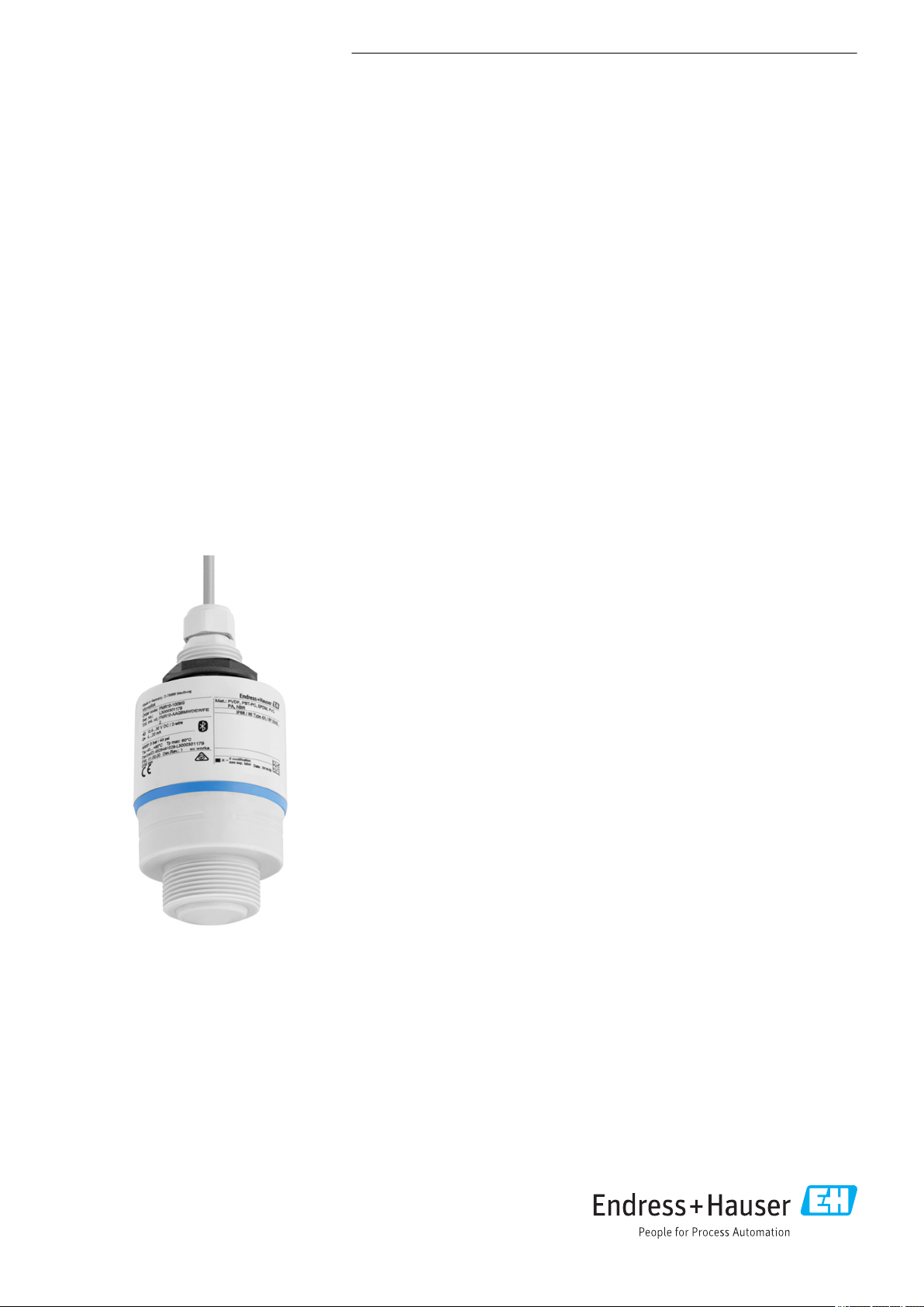
Micropilot FMR10
Free space radar
Level measurement for liquids
Application
• Ingress protection: IP66/68 / NEMA 4X/6P
• Measuring range: up to 8 m (26.25 ft)
• Process temperature: –40 to 60 °C (–40 to 140 °F)
• Process pressure: –1 to 3 bar (–14 to 43 psi)
• Accuracy: up to ± 5 mm (0.2 in)
Your benefits
• Level measurement for liquids in storage tanks, open basins, pump shafts and
canal systems
• Radar measuring device with Bluetooth® wireless technology
• Simple, safe and secure wireless remote access – ideal for installation in areas or
places difficult to reach
• Commissioning, operation and maintenance via free iOS / Android app SmartBlue
– saves time and reduces costs
• Full PVDF body – for a long sensor lifetime
• Hermetically sealed wiring and fully potted electronics – eliminates water ingress
and allows operation under harsh environmental conditions
• Most compact radar due to unique radar chip design – fits in limited space
installations
• Best price-performance-ratio radar
Page 2

Table of contents
Micropilot FMR10
Important document information ............... 3
Symbols for certain types of information .............. 3
Safety symbols ............................... 3
Electrical symbols ............................. 3
Symbols in graphics ............................ 3
Terms and abbreviations ..................... 5
Registered trademarks ....................... 5
Product life cycle ............................ 6
Engineering ................................. 6
Procurement ................................ 6
Installation ................................. 6
Commissioning ............................... 6
Operation .................................. 6
Maintenance ................................ 6
Retirement .................................. 6
Measuring principle ......................... 7
Input ...................................... 7
Output .................................... 7
Input ..................................... 8
Measured variable ............................. 8
Measuring range .............................. 8
Operating frequency ........................... 8
Transmission power ............................ 8
Output ................................... 9
Output signal ................................ 9
Digital output ................................ 9
Signal on alarm ............................... 9
Linearization ................................ 9
Electrical connection ....................... 10
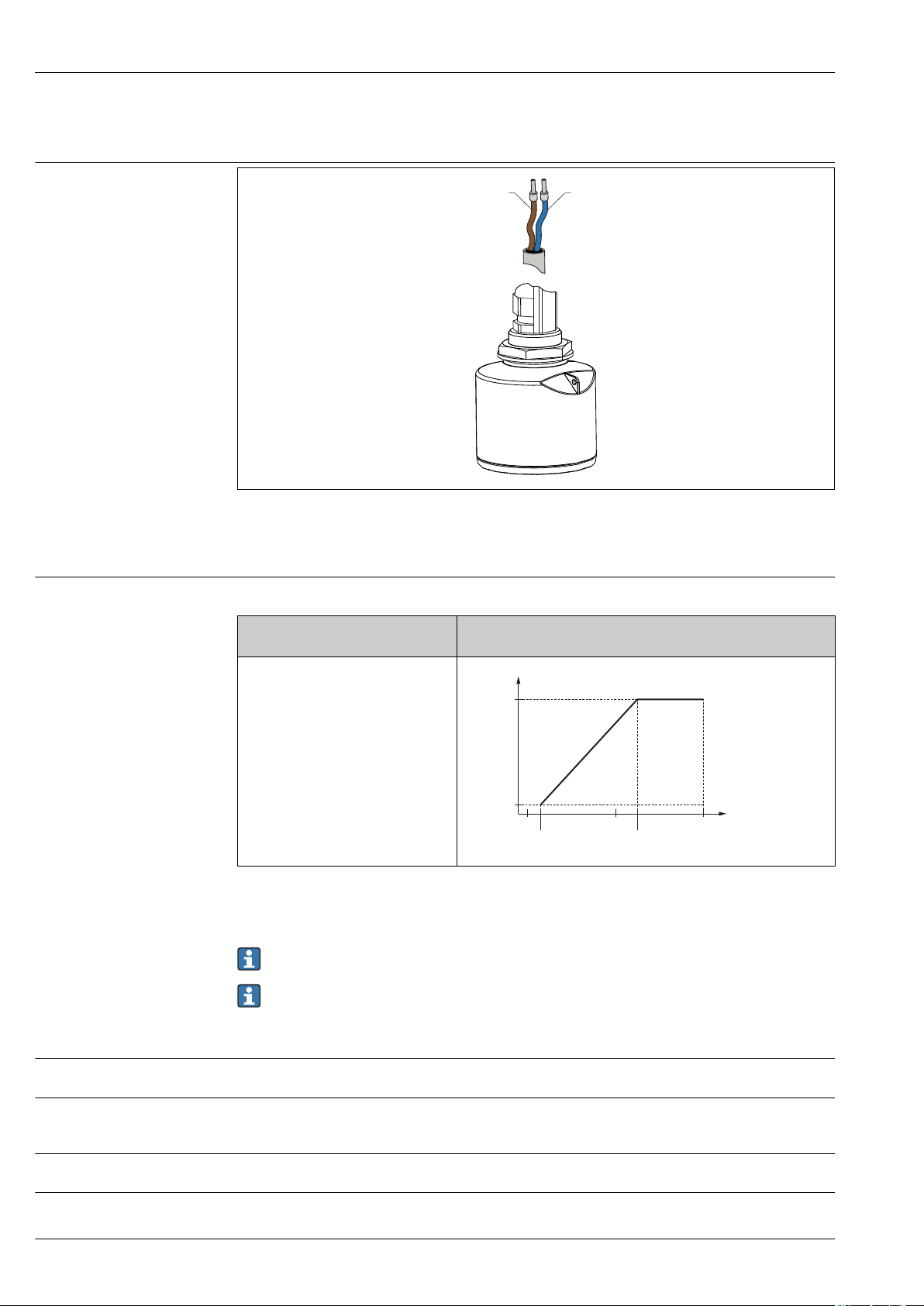
Cable assignment ............................ 10
Supply voltage .............................. 10
Power consumption ........................... 10
Current consumption .......................... 10
Starting time ............................... 10
Power supply failure .......................... 10
Connection 4 to 20 mA ........................ 11
Cable specification ............................ 11
Overvoltage protection ......................... 11
Performance characteristics .................. 12
Reference operating conditions ................... 12
Maximum measured error ....................... 12
Measured value resolution ...................... 12
Response time .............................. 12
Influence of ambient temperature ................. 13
Environment .............................. 21
Ambient temperature range ..................... 21
Storage temperature .......................... 21
Climate class ............................... 21
Installation height as per IEC 61010-1 Ed.3 ........... 21
Degree of protection .......................... 21
Vibration resistance ........................... 21
Electromagnetic compatibility (EMC) ............... 21
Process .................................. 22
Process temperature, process pressure ............... 22
Dielectric constant ............................ 22
Mechanical construction .................... 23
Dimensions ................................ 23
Weight ................................... 24
Materials .................................. 25
Connecting cable ............................. 25
Operability ............................... 26
Operating concept ............................ 26
Via Bluetooth® wireless technology ................ 26
Certificates and approvals ................... 27
CE mark ................................... 27
RoHS ..................................... 27
EAC conformity .............................. 27
RCM-Tick marking ............................ 27
Ex approval ................................ 27
Pressure equipment with allowable pressure
≤ 200 bar (2 900 psi) .......................... 27
EN 302729-1/2 radio standard ................... 27
FCC / Industry Canada ......................... 28
Japanese Radio Law and Japanese Telecommunications
Business Law Compliance ....................... 29
Other standards and guidelines ................... 29
Ordering information ....................... 30
Accessories ............................... 31
Device-specific accessories ...................... 31
Communication-specific accessories ................ 34
System components ........................... 34
Supplementary documentation ............... 35
Standard documentation ........................ 35
Installation ............................... 14
Installation conditions ......................... 14
2 Endress+Hauser
Page 3
Micropilot FMR10
A
DANGER
WARNING
CAUTION
NOTICE
1.
Important document information
Symbols for certain types of information
Safety symbols
Symbol Meaning
Permitted
Procedures, processes or actions that are permitted.
Preferred
Procedures, processes or actions that are preferred.
Forbidden
Procedures, processes or actions that are forbidden.
Tip
Indicates additional information.
Reference to documentation
Reference to page
Reference to graphic
Visual inspection
Symbol Meaning
DANGER!
This symbol alerts you to a dangerous situation. Failure to avoid this situation will result in
serious or fatal injury.
WARNING!
This symbol alerts you to a dangerous situation. Failure to avoid this situation can result in
serious or fatal injury.
CAUTION!
This symbol alerts you to a dangerous situation. Failure to avoid this situation can result in
minor or medium injury.
NOTE!
This symbol contains information on procedures and other facts which do not result in
personal injury.
Electrical symbols
Symbols in graphics
Symbol Meaning Symbol Meaning
Direct current Alternating current
Direct current and alternating current Ground connection
A grounded terminal which, as far as
the operator is concerned, is
grounded via a grounding system.
Protective ground connection
A terminal which must be connected
to ground prior to establishing any
other connections.
Symbol Meaning
1, 2, 3 ... Item numbers
, 2., 3.… Series of steps
A, B, C, ... Views
A-A, B-B, C-C, ... Sections
Equipotential connection
A connection that has to be connected
to the plant grounding system: This
may be a potential equalization line
or a star grounding system depending
on national or company codes of
practice.
Endress+Hauser 3
Page 4

Symbol Meaning
-
.
Hazardous area
Indicates a hazardous area.
Safe area (non-hazardous area)
Indicates the non-hazardous area.
Micropilot FMR10
4 Endress+Hauser
Page 5

Micropilot FMR10
Terms and abbreviations
Term/abbreviation Explanation
BA Document type "Operating Instructions"
KA Document type "Brief Operating Instructions"
TI Document type "Technical Information"
SD Document type "Special Documentation"
XA Document type "Safety Instructions"
PN Nominal pressure
MWP Maximum Working Pressure
The MWP can also be found on the nameplate.
ToF Time of Flight
DC Relative dielectric constant ε
Operating tool The term "operating tool" is used in place of the following operating software:
SmartBlue (app), for operation using an Android or iOS smartphone or tablet.
BD Blocking Distance; no signals are analyzed within the BD.
r
Registered trademarks
Bluetooth®
The Bluetooth® word mark and logos are registered trademarks owned by the Bluetooth SIG, Inc. and
any use of such marks by Endress+Hauser is under license. Other trademarks and trade names are
those of their respective owners.
Apple®
Apple, the Apple logo, iPhone, and iPod touch are trademarks of Apple Inc., registered in the U.S.
and other countries. App Store is a service mark of Apple Inc.
Android®
Android, Google Play and the Google Play logo are trademarks of Google Inc.
Endress+Hauser 5
Page 6

Product life cycle
Micropilot FMR10
Engineering
Procurement
Installation
Commissioning
Operation
Maintenance
• Proven radar measuring technology
• Indication of over-flooding situation
• 2D / 3D drawings
• Spec Sheet Producer
• Applicator Selection tool for the selection of the perfect measurement solution
Device not compatible with transmitters and sensors of ultrasonic measurement technology
(e.g. Prosonic FMU9x, FDU9x)
• Best price-performance-ratio radar
• Easy to order via Global E-direct Portal with 48h delivery time
• Global availability
Rear- and front side thread for flexible installation
• Easy and fast setup via SmartBlue (app)
• No additional tools or adapters required
• Local languages (up to 15)
• Continuous self-monitoring
• Diagnosis information acc. NAMUR NE107 with clear text messages remedy directives
• Signal curve via SmartBlue (app)
• Encrypted single point-to-point data transmission (Fraunhofer-Institut, third party, tested) and
password-protected communication via Bluetooth® wireless technology
• No maintenance required
• Technical experts on-call around the global
Retirement
• Environmentally responsible recycling concepts
• RoHS compliance (Restriction of certain hazardous substances), lead-free soldering of electronic
components
6 Endress+Hauser
Page 7
Micropilot FMR10
D
Q
R
100%
0%
D
L
F
E
Measuring principle
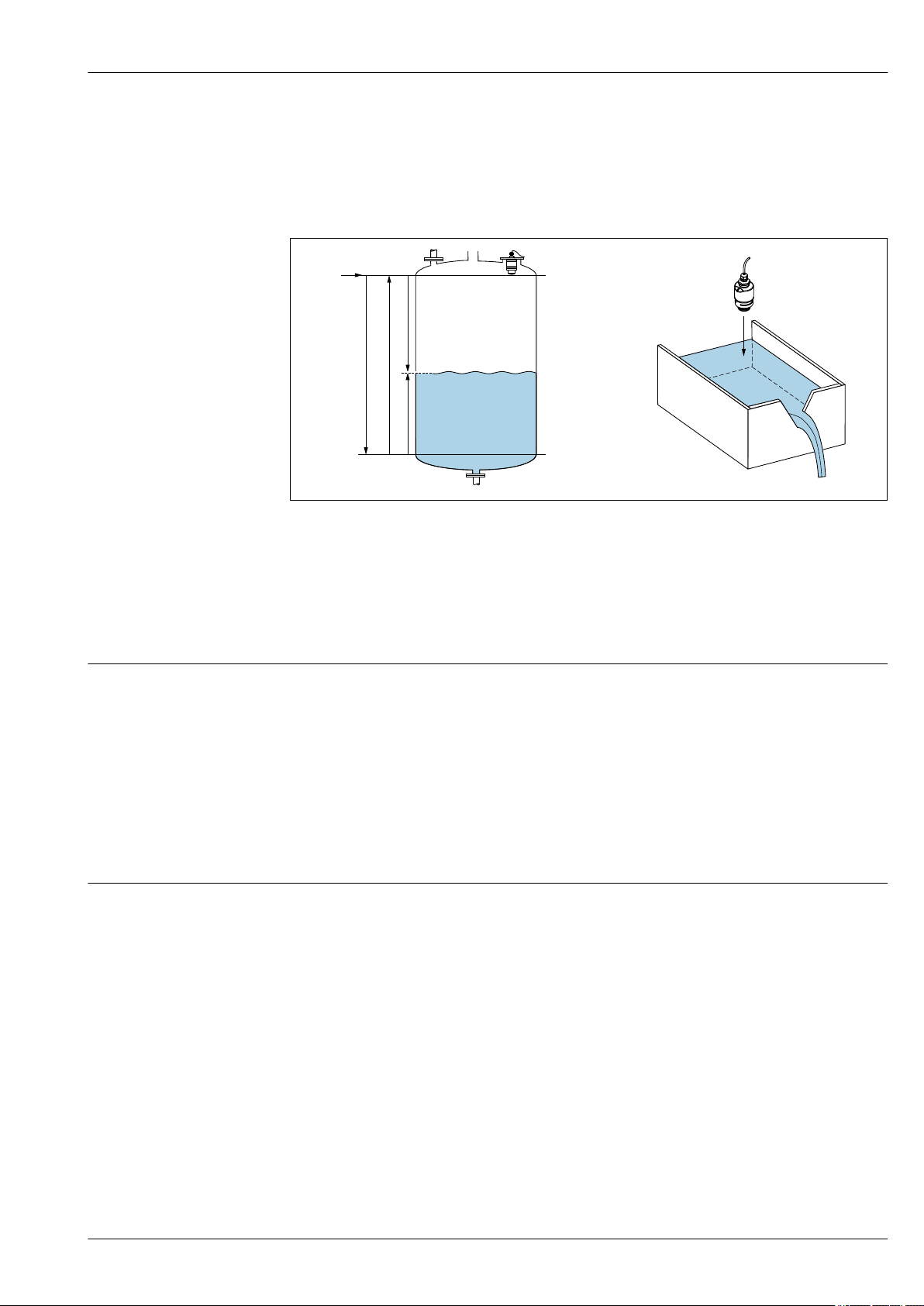
The Micropilot is a "downward-looking" measuring system, operating based on the time-of-flight
method (ToF). It measures the distance from the reference point R to the product surface. Radar
impulses are emitted by an antenna, reflected off the product surface and received again by the radar
system.
A0028409
1 Setup parameters of the Micropilot
E Empty calibration (= zero)
F Full calibration (= span)
D Measured distance
L Level (L = E - D)
Q Flow rate at measuring weirs or channels (calculated from the level using linearization)
R Reference point
Input
The reflected radar impulses are received by the antenna and transmitted into the electronics. A
microprocessor evaluates the signal and identifies the level echo caused by the reflection of the radar
impulse at the product surface. This clear signal detection system benefits from over 30 years'
experience with time-of-flight procedures.
The distance D to the product surface is proportional to the time of flight t of the impulse:
D = c · t/2,
where c is the speed of light.
Based on the known empty distance E, the level L is calculated:
L = E – D
Output
The Micropilot is adjusted by entering the empty distance E (= zero point) and the full distance F (=
span).
• Current output: 4 to 20 mA
• Digital output (SmartBlue): 0 to 5 m (0 to 16 ft) or 0 to 8 m (0 to 26.25 ft) in combination with
accessory "flooding protection tube"
Endress+Hauser 7
Page 8
Input
Micropilot FMR10
Measured variable
The measured variable is the distance between the reference point and the product surface.
The level is calculated based on E, the empty distance entered.
Measuring range Maximum measuring range
Device Maximum measuring range
FMR10 5 m (16 ft)
FMR10 with accessory "flooding protection tube" 8 m (26.25 ft)
Requirements of the installation
• Tank height > 1.5 m (5 ft)
• Open channel minimum width 0.5 m (1.6 ft)
• Calm surfaces
• No agitators
• No buildup
• Relative dielectric constant εr > 4
Usable measuring range
The usable measuring range depends on the antenna size, the medium's reflective properties, the
installation position and any possible interference reflections.
The following table describes the media groups.
Media groups
Operating frequency
Transmission power
ε
r
4 to 10 e.g. concentrated acid, organic solvents, ester, aniline, alcohol, acetone.
> 10 conductive liquids, aqueous solutions, diluted acids and bases
Example
Reduction of the max. possible measuring range by:
• Media with bad reflective properties (= low εr value)
• Formation of buildup, particularly of moist products
• Strong condensation
• Foam generation
• Freezing of sensor
K-band (~ 26 GHz)
Distance Mean power density in the direction of the beam
1 m (3.3 ft) < 12 nW/cm
5 m (16 ft) < 0.4 nW/cm
2
2
8 Endress+Hauser
Page 9

Micropilot FMR10
Output
Output signal 4 to 20 mA
An 4 to 20 mA interface is used for measured value output and to power to the device.
Digital output Bluetooth® wireless technology
The device has a Bluetooth® wireless technology interface and can be operated and configured via
this interface using the SmartBlue app.
• The range under reference conditions is 25 m (82 ft)
• Incorrect operation by unauthorized persons is prevented by means of encrypted communication
and password encryption.
• The Bluetooth® wireless technology interface can be deactivated.
Signal on alarm
Linearization
Depending on the interface, failure information is displayed as follows:
• Current output
Alarm current: 22.5 mA (as per NAMUR RecommendationNE 43)
• SmartBlue (app)
– Status signal (as per NAMUR Recommendation NE 107)
– Plain text display with remedial action
The linearization function of the device allows the conversion of the measured value into any unit of
length, weight, flow or volume.
When operating via SmartBlue (app), up to 32 value pairs can be entered manually into the
linearization table.
Endress+Hauser 9
Page 10
Cable assignment
-
+
1
2
R [ ]W
U0[V]
10
10.5 21.75
20 30
0
500
Micropilot FMR10
Electrical connection
A0028954
2 Cable assignment
1 Plus, brown wire
2 Minus, blue wire
Supply voltage
An external power supply is necessary.
Terminal voltage U at device Maximum load R, depending on supply voltage U0 of power supply
unit
10.5 to 30 VDC 2-wire
A0029226
Potential equalization
No special measures for potential equalization are required.
Various power supply units can be ordered from Endress+Hauser.
Battery operation
The sensor's Bluetooth® wireless technology communication can be disabled to increase the
operating life of the battery.
Power consumption
Current consumption
Starting time
Power supply failure
10 Endress+Hauser
Maximum input power: 675 mW
• maximum input current: <25 mA
• Maximum start-up current: 3.6 mA
First stable measured value after 20 s (with supply voltage = 24 VDC)
The configuration remains stored in the sensor.
Page 11

Micropilot FMR10
2
Y
+ +
- -
I
1
mA
Connection 4 to 20 mA
Cable specification
Overvoltage protection
Circuit diagram / Description
FMR10 connection with voltage source
and 4 to 20 mA display
A0028907
3 FMR10 block diagram
1 Micropilot FMR10, 4 to 20 mA
2 Power supply
Unshielded cable, 2 × 0.75 mm
2
• UV- and weather-resistant acc. ISO 4892-2
• Flame retardant acc. IEC 60332-1-2
As per IEC/EN 60079-11 section 10.9, the cable is designed for a tensile strength of 30 N (6.74 lbf)
(over a period of 1 h).
The FMR10 is supplied with 10 m (33 ft) cable length as standard.
The device is equipped with integrated overvoltage protection.
Endress+Hauser 11
Page 12
Performance characteristics
0
0.5 (1.67)
D[m ](ft)
∆
[mm (in)]
5 (0.2)
10 (0.39)
-20 (-0.79)
20 (0.79)
-5 (-0.2)
-10 (-0.39)
R
0.1 (0.33)
R
Micropilot FMR10
Reference operating conditions
Maximum measured error
• Temperature = +24 °C (+75 °F) ±5 °C (±9 °F)
• Pressure = 960 mbar abs. (14 psia) ±100 mbar (±1.45 psi)
• Humidity = 60 % ±15 %
• Reflector: metal plate with diameter ≥ 1 m (40 in)
• No major interference reflections inside the signal beam
Typical data under reference operating conditions: DIN EN 61298-2, percentage values in relation to
the span.
Device Value Output
1)
digital
FMR10 Sum of non-linearity, non-repeatability and hysteresis ±5 mm (±0.2 in) ±0.02 %
Offset/Zero ±4 mm (±0.16 in) ±0.03 %
1) SmartBlue (app)
2) Only relevant for 4-20mA current output; add error of the analog value to the digital value
analog
2)
Differing values in near-range applications
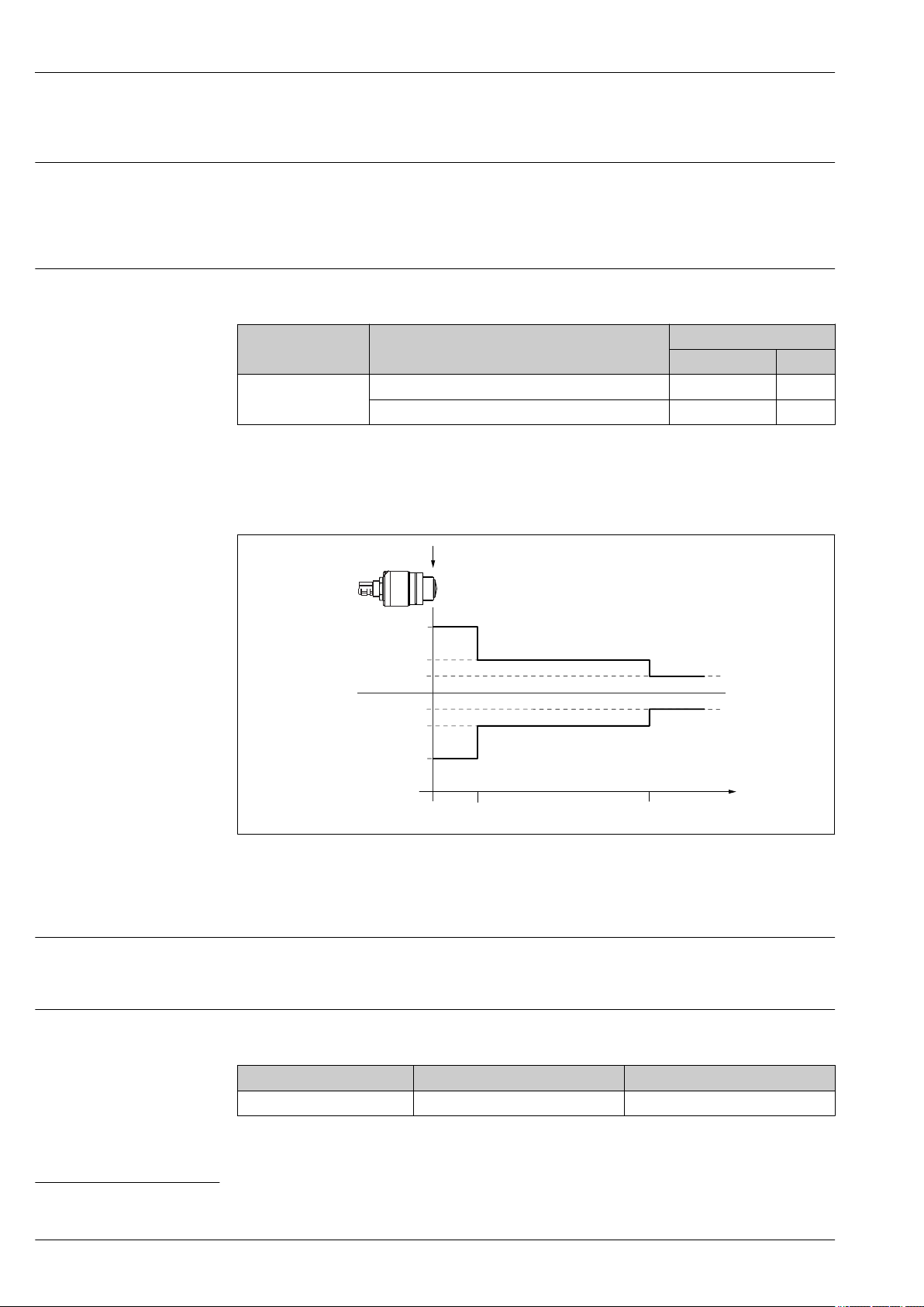
4 Maximum measured error in near-range applications
∆ Maximum measured error
R Reference point of the distance measurement
D Distance from reference point of antenna
Measured value resolution
Dead band as per EN61298-2:
• Digital: 1 mm (0.04 in)
• Analog: 4 µA
Response time
The response time can be configured. The following step response times (as per DIN EN 61298-2)
apply if the damping is switched off:
Tank height Sampling rate Response time
<5 m (16 ft) 1 s
-1
<3 s
1) According to DIN EN 61298-2 the step response time is the time which passes after a sudden change of the input signal until the output signal
assumes 90% of the steady-state value for the first time.
12 Endress+Hauser
A0033273
1)
Page 13

Micropilot FMR10
Influence of ambient temperature
The measurements are carried out in accordance with EN 61298-3.
• Digital (Bluetooth® wireless technology):
Standard version: average TK = ±3 mm (±0.12 in)/10 K
• Analog (current output):
– Zero point (4 mA): average TK = 0.02 %/10 K
– Span (20 mA): average TK = 0.05 %/10 K
Endress+Hauser 13
Page 14
Installation
A
B
DC
L
D
L
D
Installation conditions Installation types
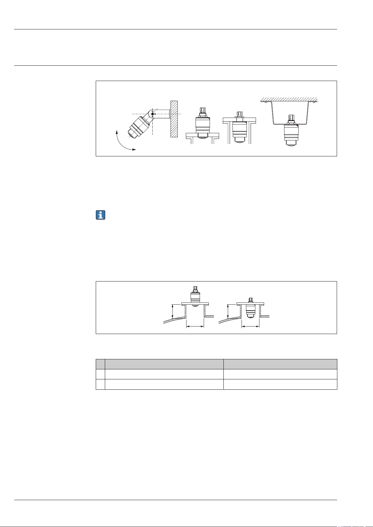
5 Wall, ceiling or nozzle installation
A Wall or ceiling mount, adjustable
B Mounted at front thread
C Mounted at rear thread
D Ceiling installation with counter nut (included in delivery)
Micropilot FMR10
A0028892
Caution!
• The sensor cables are not designed as supporting cables. Do not use as a suspension wire.
• In the free-field, a vertically downward orientation must be ensured at all times
Nozzle installation
The antenna should be just out of the nozzle for optimum measurement. The interior of the nozzle
must be smooth and may not contain any edges or welded joints. The edge of the nozzle should be
rounded if possible. The maximum nozzle length L depends on the nozzle diameter D. Please note
the specified limits for the diameter and length of the nozzle.
A0028843
6 FMR10 nozzle installation
40 mm (1.5 in) Antenna, outside nozzle 40 mm (1.5 in)Antenna, inside nozzle
D min. 40 mm (1.5 in) min. 80 mm (3 in)
L max. D × 1,5 max. 140 mm (5.5 in) + D × 1,5
14 Endress+Hauser
Page 15
Micropilot FMR10
A
BD
D
Orientation
A0028410
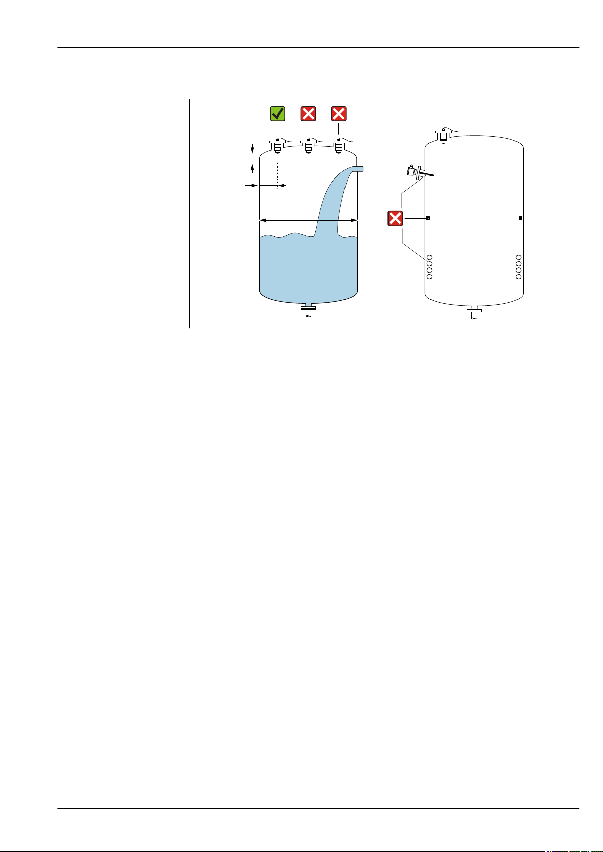
7 Tank installation position
• If possible install the sensor so that its lower edge projects into the vessel.
• Recommended distance A wall - nozzle outer edge: ~ 1/6 of the tank diameter D. However, the
device must not under any circumstances be mounted closer than 15 cm (5.91 in) to the tank wall.
• Do not mount the sensor in the center of the tank.
• Avoid measurements through the filling curtain.
• Avoid equipment such as limit switches, temperature sensors, baffles, heating coils etc.
• Several devices can be operated in a single tank without impacting on each other.
• No signals are analyzed within the Blocking distance (BD). It can therefore be used to suppress
interference signals (e.g. the effects of condensate) close to the antenna.
An automatic Blocking distance of at least 0.1 m (0.33 ft) is configured as factory setting.
However, this can be overwritten manually (0 m (0 ft) is also permitted).
Automatic calculation:
Blocking distance = Empty calibration - Full calibration - 0.2 m (0.656 ft).
Each time a new entry is made in the Empty calibration parameter orFull calibration parameter,
the Blocking distance parameter is recalculated automatically using this formula.
If the result of the calculation is a value <0.1 m (0.33 ft), the Blocking distance of0.1 m (0.33 ft)
continues to be used.
Endress+Hauser 15
Page 16
Micropilot FMR10
90°
90°
90°
90°
90°
Alignment
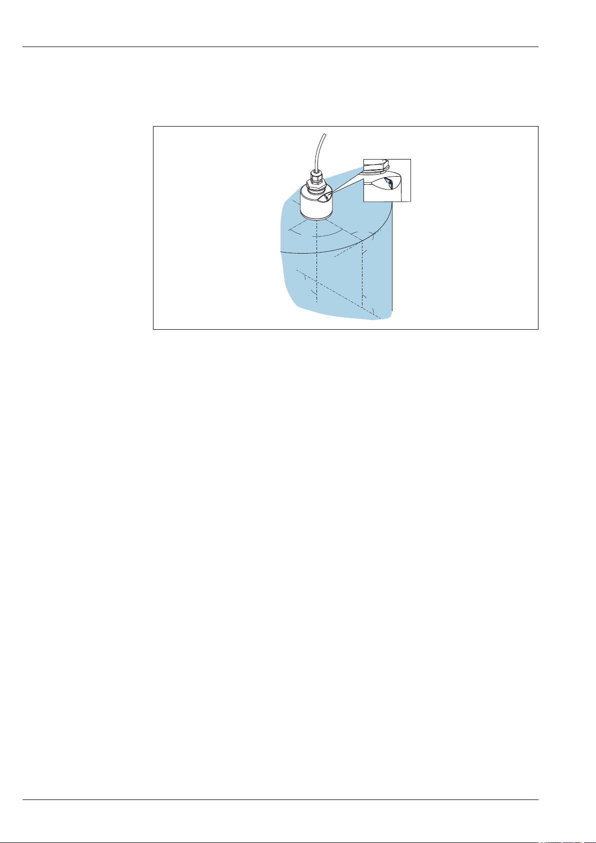
• Align the antenna vertically to the product surface.
• Align the eyelet with the mounting eye as well as possible towards the tank wall.
8 Sensor alignment when mounting in tank
A0028927
16 Endress+Hauser
Page 17
Micropilot FMR10
_
2
α
W = 2 × D × tan
α
D
W
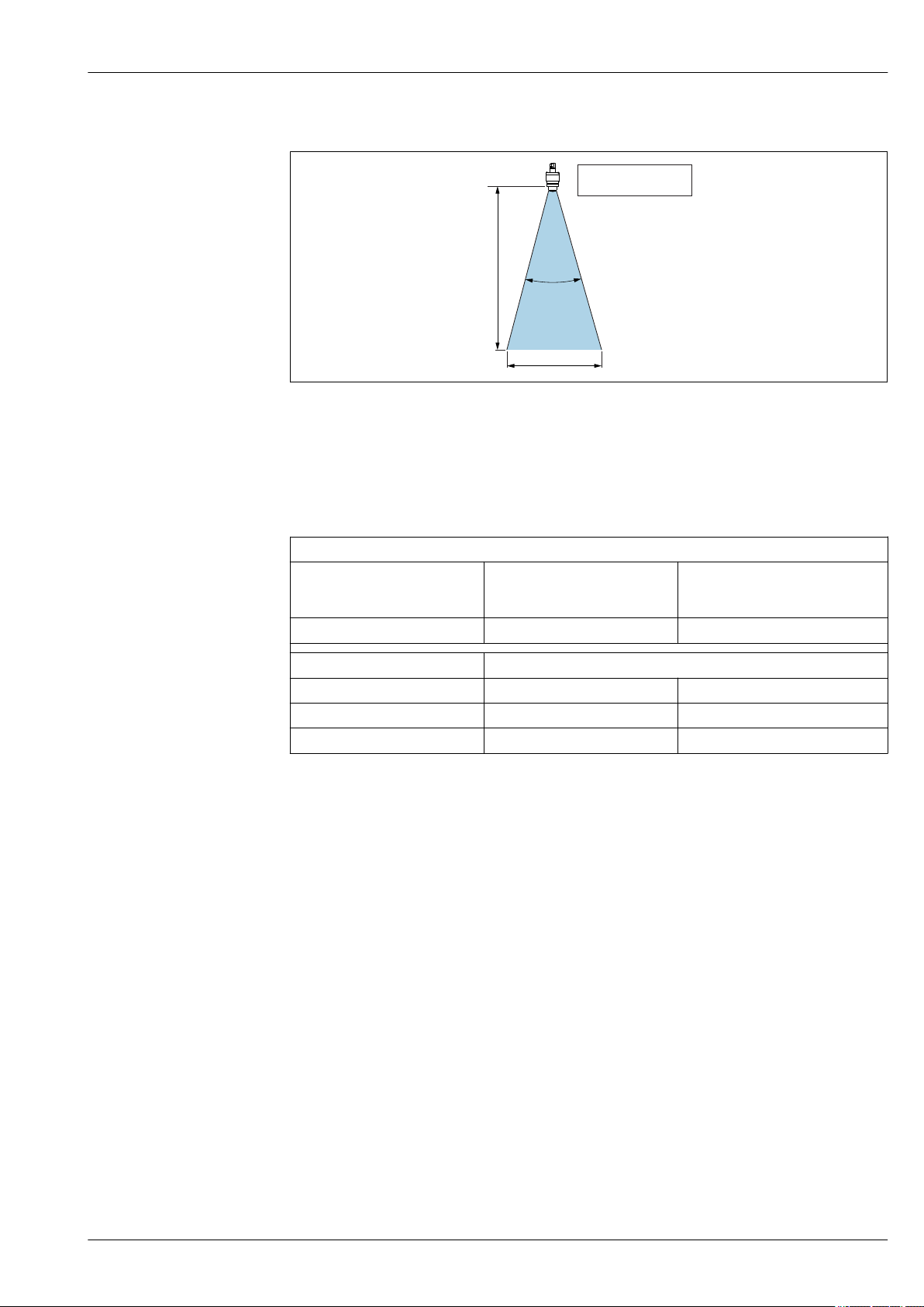
Beam angle
A0033201
9 Relationship between beam angle α, distance D and beam diameter W
The beam angle is defined as the angle α, at which the power density of the radar waves reaches half
the value of the maximum power density (3dB width). Microwaves are also emitted outside the
signal beam and can be reflected off interfering installations.
Beam diameter W as a function of beam angle α and distance D.
FMR10
Antenna size 40 mm (1.5 in) 40 mm (1.5 in)
with accessory
"flooding protection tube"
Beam angle α 30° 12°
Distance (D) Beam diameter W
3 m (9.8 ft) 1.61 m (5.28 ft) 0.63 m (2.07 ft)
5 m (16.4 ft) 2.68 m (8.79 ft) 1.51 m (4.95 ft)
8 m (26.25 ft) - 1.68 m (5.52 ft)
Endress+Hauser 17
Page 18
Micropilot FMR10
3
1
2
Measurement in plastic vessels
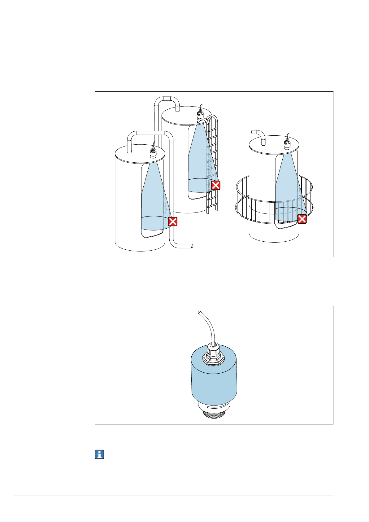
If the outer wall of the vessel is made of a non-conductive material (e.g. GFR) microwaves can also be
reflected off interfering installations outside of the vessel (e.g. metallic pipes (1), ladders (2),
grates (3), ...). Therefore there should be no such interfering installations in the signal beam. For
more information, please contact Endress+Hauser.
10 Measurement in a plastic vessel
Weather protection cover
For outdoor use, a weather protection cover is recommended.
11 Weather protection cover, e.g. with 40 mm (1.5") antenna
A0029540
A0031277
The sensor is not completely covered.
The weather protection cover is available as an accessory. → 31
18 Endress+Hauser
Page 19
Micropilot FMR10
3
4
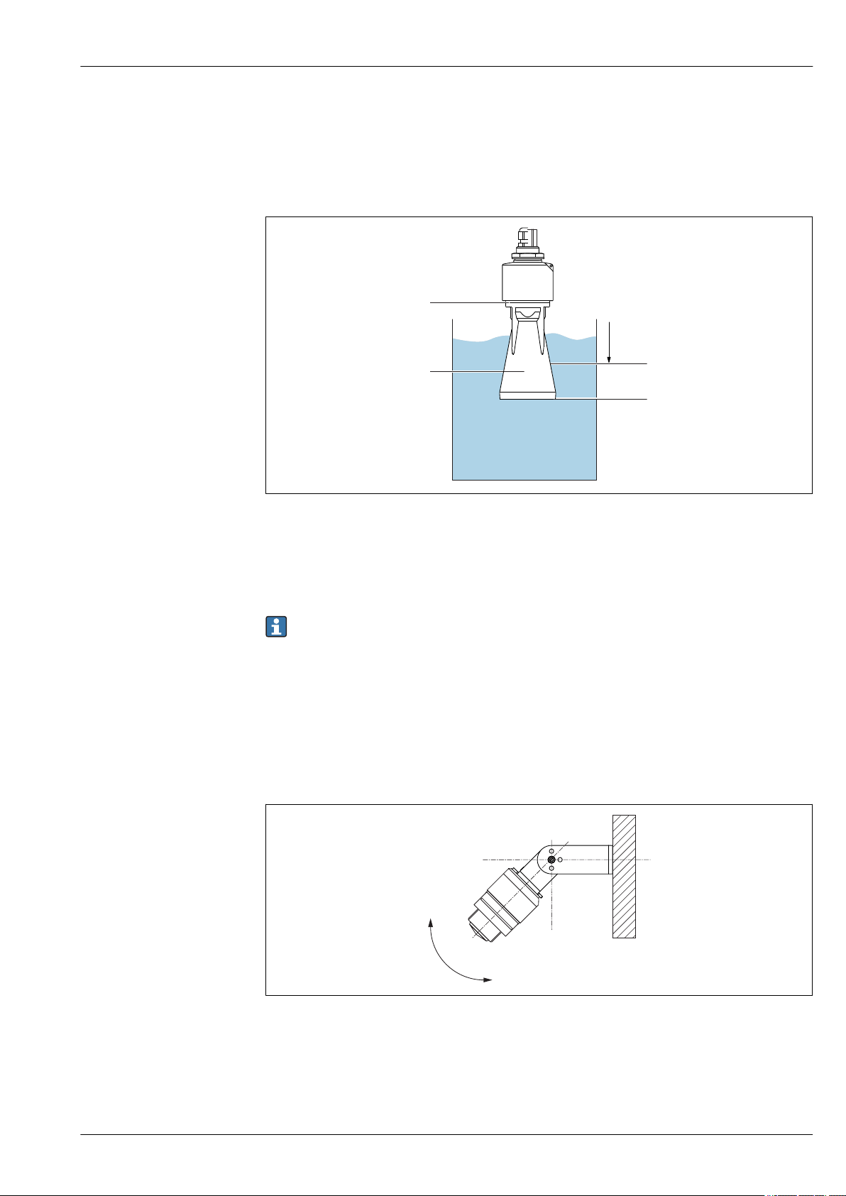
Free-field measurement with flooding protection tube
The flooding protection tube guarantees a definitive analysis of the maximum level even in the event
that the sensor is completely flooded.
In free-field installations and / or in applications where there is a risk of flooding, the flooding
protection tube must be used.
12 Function of flooding protection tube
1 Air pocket
2 O-ring (EPDM) seal
3 Blocking distance
4 Max. Level
Flooding protection tube 40 mm (1.5 in) Antenna, metallized PBT-PC:
For use with devices in product structure, feature 100 "Process connection front", option WFE
"Thread ISO228 G1-1/2".
The flooding protection tube can be ordered with the device. Product structure, feature 620
"Accessory enclosed", option R7 "Flooding protection tube, metallized PBT-PC suitable for
40 mm (1.5 in) antenna with G1-1/2 process connection on front, extended measuring range
8 m (26.25 ft) liquid".
Alternatively available as an accessory; order number 71325090.
Installation with mounting bracket, adjustable
A0030394
A0028893
13 Installation with mounting bracket, adjustable
• Wall or ceiling installation is possible.
• Using the mounting bracket, position the antenna so that it is perpendicular to the product
surface.
Endress+Hauser 19
Page 20
Micropilot FMR10
A
B
C
NOTICE
There is no conductive connection between the mounting bracket and transmitter housing.
Risk of electrostatic charge.
Integrate the mounting bracket in the local potential equalization system.
‣
The mounting bracket is available as an accessory. → 31
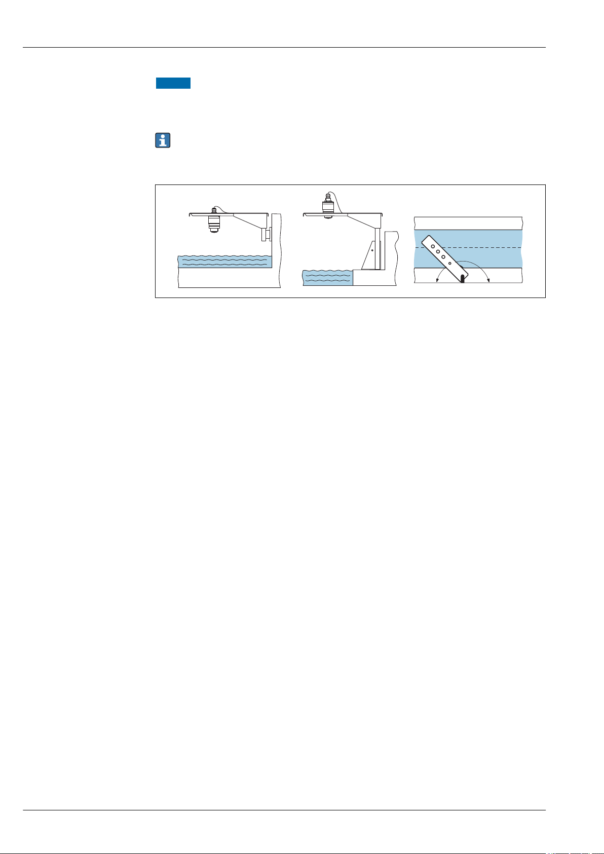
Cantilever installation, with pivot
A0028412
14 Cantilever installation, with pivot
A Installation with cantilever and wall bracket
B Installation with cantilever and mounting frame
C The cantilever can be turned (e.g. in order to position the sensor over the center of the channel, for example)
20 Endress+Hauser
Page 21

Micropilot FMR10
Environment
Ambient temperature range
Storage temperature
Climate class
Installation height as per IEC 61010-1 Ed.3
Degree of protection
Vibration resistance
Electromagnetic compatibility (EMC)
Measuring device: –40 to +60 °C (–40 to +140 °F)
Outdoor operation in strong sunlight:
• Mount the device in the shade.
• Avoid direct sunlight, especially in warmer climatic regions.
• Use a weather protection cover → 31.
–40 to +80 °C (–40 to +176 °F)
DIN EN 60068-2-38 (test Z/AD)
Generally up to 2 000 m (6 600 ft) above sea level.
Tested acc. to:
– IP66, NEMA 4X
– IP68, NEMA 6P (24 h at 1.83 m (6.00 ft) under water)
DIN EN 60068-2-64 / IEC 60068-2-64: 20 to 2 000 Hz, 1 (m/s2)2/Hz
Electromagnetic compatibility in accordance with all of the relevant requirements outlined in the
EN 61000 series and NAMUR Recommendation EMC (NE 21). For details, please refer to the
Declaration of Conformity
2)
2) Available for download at www.endress.com.
Endress+Hauser 21
Page 22
Process
p
-40
+60 ( 40)+1
0 ( )+32
T
p
[ °F ]°C ( )
-1( )-14.5
0
3 (43.5)
Micropilot FMR10
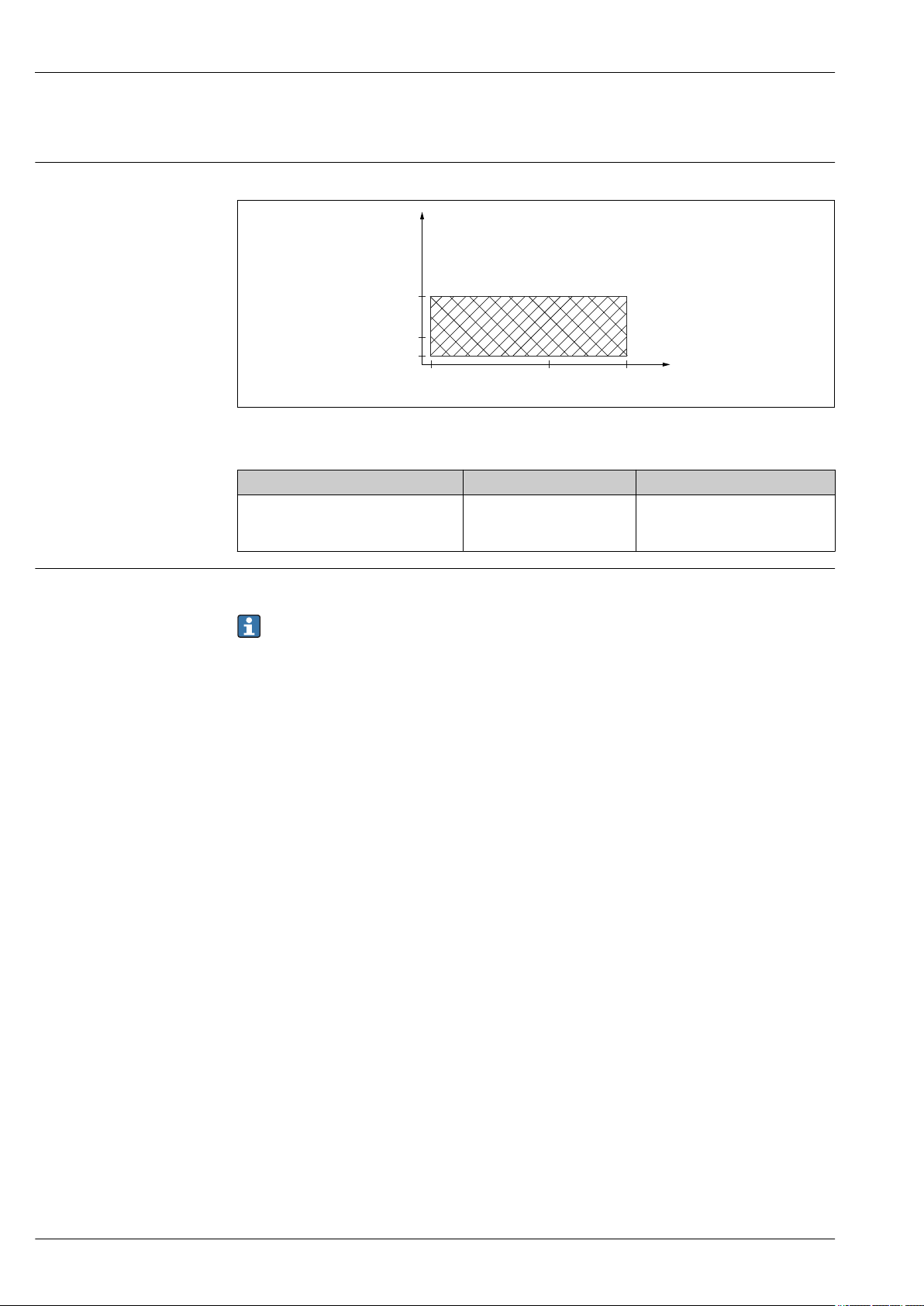
Process temperature, process pressure
Dielectric constant
FMR10
15 FMR10: Permitted range for process temperature and process pressure
Feature 100 "Process connection" Process temperature range Process pressure range
• VEE: Thread ASME MNPT1-1/2;
PVDF
• WFE: Thread ISO228 G1-1/2; PVDF
–40 to +60 °C (–40 to +140 °F) p
= –1 to 3 bar (–14.5 to 43.5 psi)
rel
p
< 4 bar (58 psi)
abs
For liquids
εr ≥ 4
For dielectric constants (DC values) of many media commonly used in various industries refer
to:
• the Endress+Hauser DC manual (CP01076F)
• the Endress+Hauser "DC Values App" (available for Android and iOS)
A0030443-EN
22 Endress+Hauser
Page 23
Micropilot FMR10
G 1 1/2"
20 (0.79)
G 1"
NPT 1"
26 (1.02)
ø75 (2.95)
28 (1.1)
140 (5.5)
112 (4.4)
NPT 1 1/2"
A
B
Mechanical construction
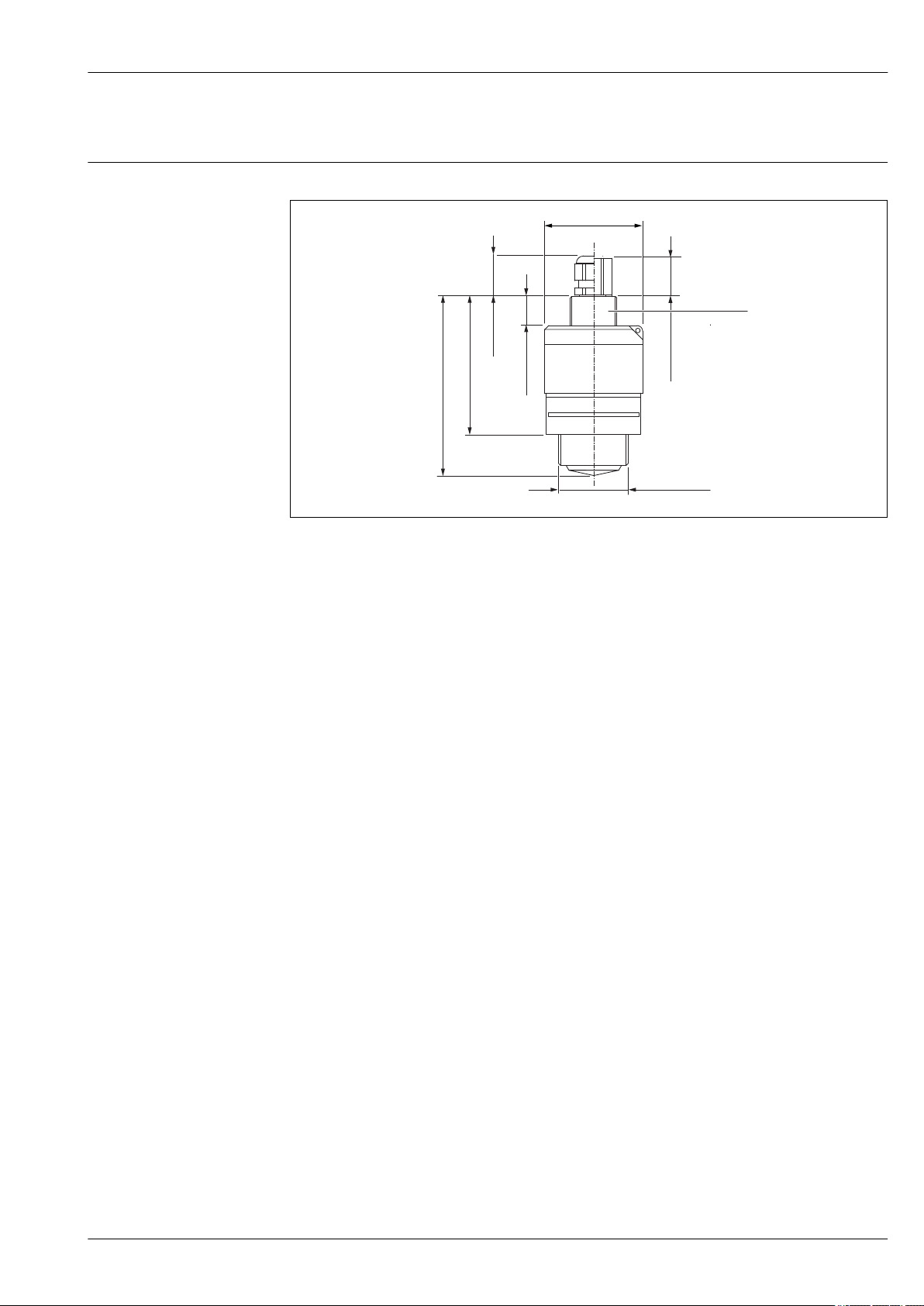
Dimensions 40 mm (1.5 in) antenna with G 1-1/2" or MNPT 1-1/2" thread
16 Dimensions process connection G 1-1/2" or MNPT 1-1/2" thread,engineering unit:mm (in)
A Cable gland
B FNPT 1/2" conduit connection
Applies to the following device versions
• Feature 095 "Process connection rear side"
– VCE: Thread ASME MNPT1; PVDF; FNPT 1/2" conduit connection
– WDE: Thread G1 ISO228; PVDF; cable gland
• Feature 100 "Process connection front side"
– VEE: Thread ASME MNPT1-1/2; PVDF
– WFE: Thread ISO228 G1-1/2; PVDF
A0028805
Endress+Hauser 23
Page 24
Micropilot FMR10
!89 (3.5)
264 (10.4)
!75 (2.95)
8 (0.31)
G 1"
1
2 (0.08)
41 mm
2 (0.08)
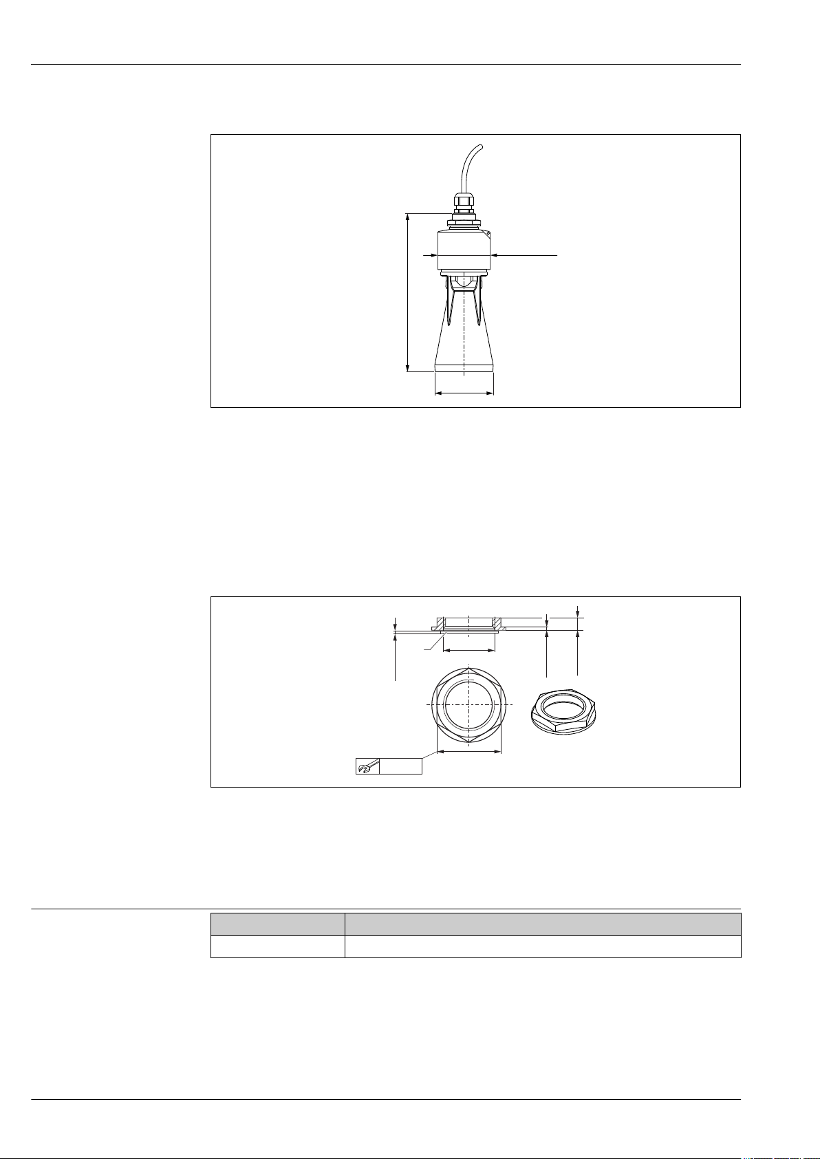
40 mm (1.5 in) antenna with flooding protection tube
A0030266
17 Dimensions 40 mm (1.5 in) antenna with mounted flooding protection tube, engineering unit: mm (in)
Applies to the following device versions
• Feature 100 "Process connection front side"
WFE: Thread ISO228 G1-1/2; PVDF
• Feature 620 "Accessory enclosed"
Option R7 "Flooding protection tube, metallized PBT-PC suitable for 40 mm (1.5 in) antenna with
process connection on front G1-1/2", extended measuring range 8 m (26.25 ft) liquids.
Counter nut for process connection rear side
18 Dimensions of counter nut for process connection rear side, engineering unit: mm (in)
1 Seal
A0028419
• The counter nut with seal (EPDM) is included in the scope of supply.
• Material: PA6.6
Weight
Micropilot Weight (incl. 10 m (32.8 ft) cable)
FMR10 Approx. 3.0 kg (6.6 lb)
24 Endress+Hauser
Page 25
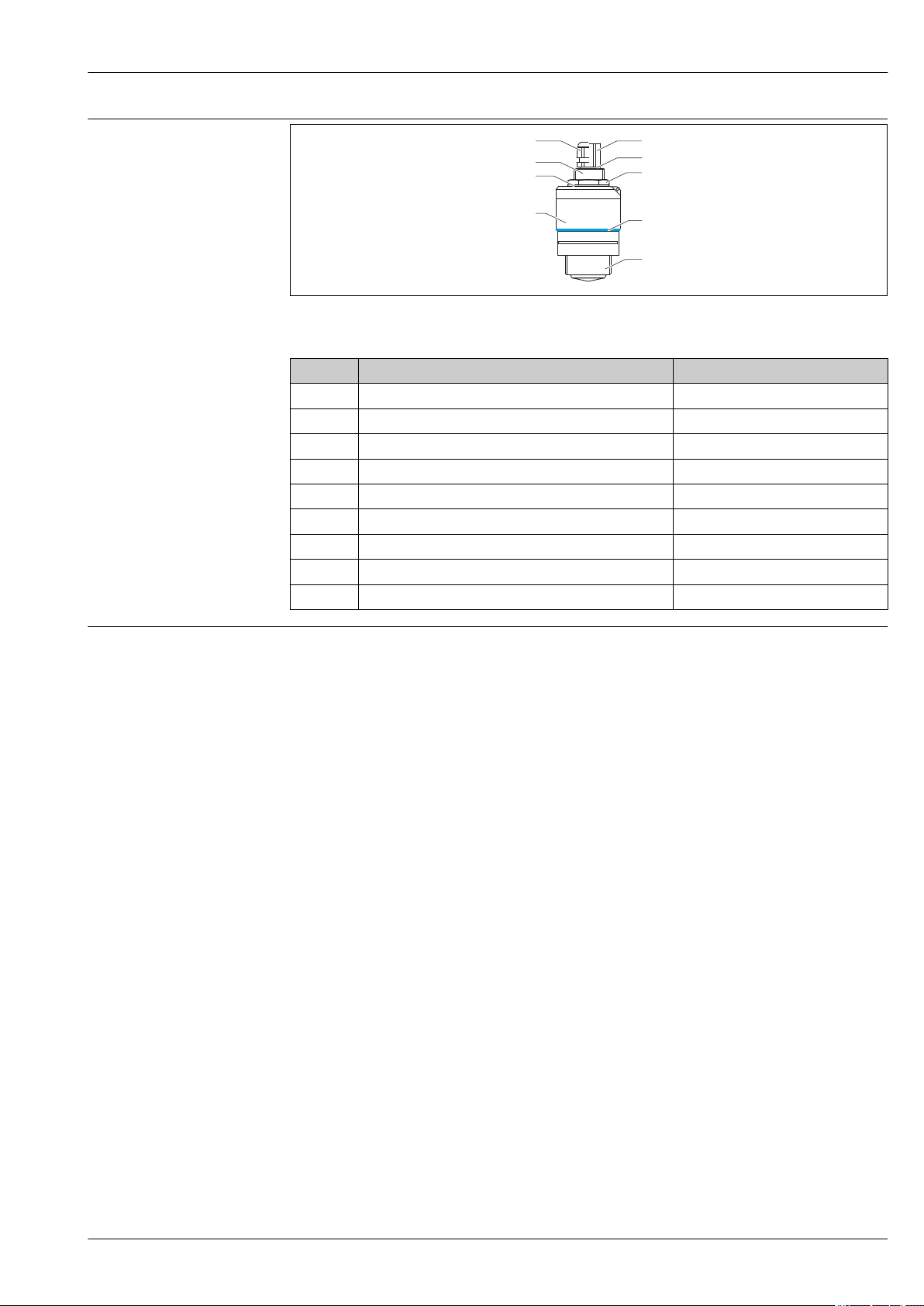
Micropilot FMR10
1
8
9
2
3
4 5
6
7
Materials
A0028415
19 FMR10 materials
Item Component part Material
1 Sensor housing PVDF
2 Seal EPDM
3 Process connection rear side PVDF
4 Cable gland PA
5 Conduit connection adapter CuZn, nickel-plated
6 O-ring EPDM
7 Counter nut PA6.6
8 Design ring PBT PC
9 Process connection front side PVDF
Connecting cable
Standard length: 10 m (33 ft)
If longer cable lengths are required, an extension cable must be used.
In this case, the total cable length (sensor cable + extension cable) must not exceed 300 m (984 ft).
Material : PVC
Endress+Hauser 25
Page 26
Operability
1
2
3
Micropilot FMR10
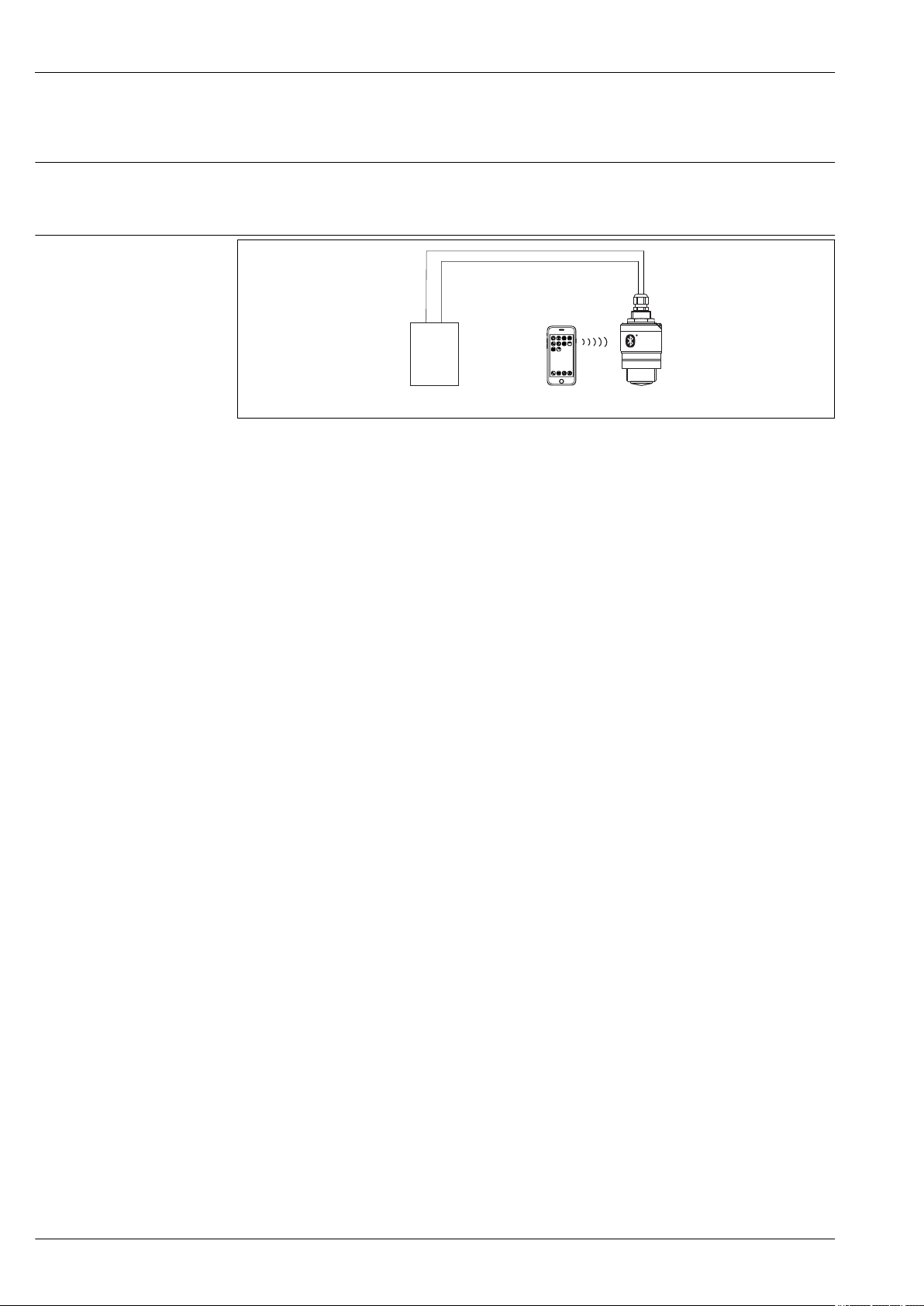
Operating concept
Via Bluetooth® wireless technology
• 4 to 20 mA
• SmartBlue (app) via Bluetooth® wireless technology
• Menu guidance with brief explanations of the individual parameter functions in the operating tool
A0028895
20 Possibilities for remote operation via Bluetooth® wireless technology
1 Transmitter power supply unit
2 Smartphone / tablet with SmartBlue (app)
3 Transmitter with Bluetooth® wireless technology
26 Endress+Hauser
Page 27
Micropilot FMR10
Certificates and approvals
Availability of approvals and certificates can be called up daily via the product configurator.
→ 30
CE mark
RoHS
EAC conformity
RCM-Tick marking
Ex approval
The measuring system meets the legal requirements of the applicable EC guidelines. These are listed
in the corresponding EC Declaration of Conformity together with the standards applied.
Endress+Hauser confirms successful testing of the device by affixing to it the CE mark.
The measuring system complies with the substance restrictions of the Restriction on Hazardous
Substances Directive 2011/65/EU (RoHS 2).
The measuring system meets the legal requirements of the applicable EAC guidelines. These are
listed in the corresponding EAC Declaration of Conformity together with the standards applied.
Endress+Hauser confirms successful testing of the device by affixing to it the EAC mark.
The supplied product or measuring system meets the ACMA (Australian Communications and Media
Authority) requirements for network integrity, interoperability, performance characteristics as well
as health and safety regulations. Here, especially the regulatory arrangements for electromagnetic
compatibility are met. The products are labelled with the RCM- Tick marking on the name plate.
A0029561
• Non-hazardous area
• CSA C/US General Purpose
• Non-hazardous area + EAC mark
Pressure equipment with
allowable pressure
≤ 200 bar (2 900 psi)
EN 302729-1/2 radio standard
Pressure instruments with a flange and threaded boss that do not have a pressurized housing do not
fall within the scope of the Pressure Equipment Directive, irrespective of the maximum allowable
pressure.
Reasons:
According to Article 2, point 5 of EU Directive 2014/68/EU, pressure accessories are defined as
"devices with an operational function and having pressure-bearing housings".
If a pressure instrument does not have a pressure-bearing housing (no identifiable pressure chamber
of its own), there is no pressure accessory present within the meaning of the Directive.
Note:
A partial examination shall be performed for pressure instruments that are part of safety equipment
for the protection of a pipe or vessel from exceeding allowable limits (equipment with safety
function in accordance with Pressure Equipment Directive 2014/68/EU, Article 2, point 4).
The Micropilot FMR10 devices comply with the LPR (Level Probing Radar) radio standard EN
302729-1/2. The devices are approved for unrestricted use inside and outside of closed vessels in
countries of the EU and EFTA. that have implemented this standard.
The following countries are those that have currently implemented the directive:
Belgium, Bulgaria, Germany, Denmark, Estonia, France, Greece, UK, Ireland, Iceland, Italy,
Liechtenstein, Lithuania, Latvia, Malta, The Netherlands, Norway, Austria, Poland, Portugal,
Romania, Sweden, Switzerland, Slovakia, Spain, Czech Republic and Cyprus.
Implementation is still underway in all of the countries not listed.
Please note the following for operation of the devices outside of closed vessels:
1. The device must be mounted in accordance with the instructions in the "Installation" section.
→ 19
Endress+Hauser 27
Page 28
Micropilot FMR10
2. Installation must be carried out by properly trained, expert staff.
3. The device antenna must be installed in a fixed location pointing vertically downwards.
4. The installation site must be located at a distance of 4 km from the astronomy stations listed
below or otherwise approval must be provided by the relevant authority. If the device is
installed at a distance of 4 to 40 km from one of the listed stations, it must not be installed at a
height of more than 15 m (49 ft) above the ground.
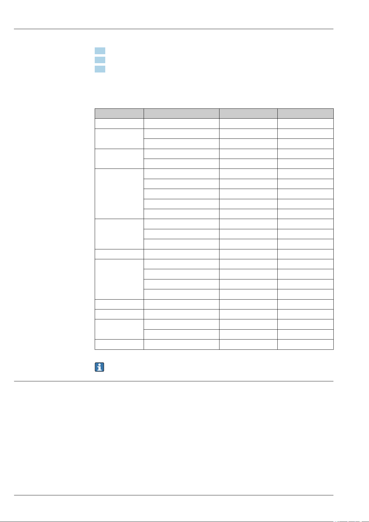
Astronomy stations
Country Name of the station Latitude Longitude
Germany Effelsberg 50°31'32" North 06°53'00" East
Finland Metsähovi 60°13'04" North 24°23'37" East
Tuorla 60°24'56" North 24°26'31" East
France Plateau de Bure 44°38'01" North 05°54'26" East
Floirac 44°50'10" North 00°31'37" West
Great Britain Cambridge 52°09'59" North 00°02'20" East
Damhall 53°09'22" North 02°32'03" West
Jodrell Bank 53°14'10" North 02°18'26" West
Knockin 52°47'24" North 02°59'45" West
Pickmere 53°17'18" North 02°26'38" West
Italy Medicina 44°31'14" North 11°38'49" East
Noto 36°52'34" North 14°59'21" East
Sardinia 39°29'50" North 09°14'40" East
Poland Fort Skala Krakow 50°03'18" North 19°49'36" East
Russia Dmitrov 56°26'00" North 37°27'00" East
Kalyazin 57°13'22" North 37°54'01" East
Pushchino 54°49'00" North 37°40'00" East
Zelenchukskaya 43°49'53" North 41°35'32" East
Sweden Onsala 57°23'45" North 11°55'35" East
Switzerland Bleien 47°20'26" North 08°06'44" East
Spain Yebes 40°31'27" North 03°05'22" West
Robledo 40°25'38" North 04°14'57" West
Hungary Penc 47°47'22" North 19°16'53" East
As a general rule, the requirements outlined in EN 302729-1/2 must be observed.
FCC / Industry Canada
This device complies with Part 15 of the FCC Rules [and with Industry Canada licence-exempt RSS
standard(s)]. Operation is subject to the following two conditions: (1) this device may not cause
harmful interference, and (2) this device must accept any interference received, including
interference that may cause undesired operation.
Le présent appareil est conforme aux CNR d'Industrie Canada applicables aux appareils radio exempts
de licence. L'exploitation est autorisée aux deux conditions suivantes: (1) l'appareil ne doit pas produire
de brouillage, et (2) l'utilisateur de l'appareil doit accepter tout brouillage radioélectrique subi, même si
le brouillage est susceptible d'en compromettre le fonctionnement.
28 Endress+Hauser
Page 29
Micropilot FMR10
202-LSF004
R
[Any] Changes or modifications made to this equipment not expressly approved by Endress+Hauser
may void the FCC authorization to operate this equipment.
This equipment has been tested and found to comply with the limits for a Class B digital device,
pursuant to Part 15 of the FCC Rules. These limits are designed to provide reasonable
protection against harmful interference in a residential installation. This equipment generates,
uses and can radiate radio frequency energy and, if not installed and used in accordance with
the instructions, may cause harmful interference to radio communications. However, there is no
guarantee that interference will not occur in a particular installation. If this equipment does
cause harmful interference to radio or television reception, which can be determined by turning
the equipment off and on, the user is encouraged to try to correct the interference by one or
more of the following measures:
• Reorient or relocate the receiving antenna
• Increase the separation between the equipment and receiver
• Connect the equipment into an outlet on a circuit different from that to which the receiver is
connected
• Consult the dealer or an experienced radio/TV technician for help
• The installation of the LPR/TLPR device shall be done by trained installers, in strict
compliance with the manufacturer’s instructions.
• The use of this device is on a “no-interference, no-protection” basis. That is, the user shall
accept operations of high-powered radar in the same frequency band which may interfere
with or damage this device. However, devices found to interfere with primary licensing
operations will be required to be removed at the user’s expense.
• Only for usage without the accessory “flooding protection tube”, i.e. NOT in the free-field:
This device shall be installed and operated in a completely enclosed container to prevent RF
emissions, which can otherwise interfere with aeronautical navigation.
Japanese Radio Law and Japanese Telecommunications Business Law Compliance
Other standards and guidelines
This device is granted pursuant to the Japanese Radio Law (電波法) and the Japanese
Telecommunications Business Law (電気通信事業法). This device should not be modified (otherwise
the granted designation number will become invalid).
Certified No.: 202-LSF004
The products are labelled with the Technical Conformity Mark (GITEKI) from Japanese Ministry of
Internal Affairs and Communications (MIC) on the name plate.
A0032960
• IEC/EN 61010-1
Safety Requirements for Electrical Equipment for Measurement, Control and Laboratory Use
• IEC/EN 55011
"EMC Emission, RF Emission for Class B". Industrial, scientific and medical equipment –
Electromagnetic disturbance characteristics - Limits and methods of measurement
• IEC/EN 61000-4-2
EMC Immunity, ESD (Performance Criteria A). Electromagnetic compatibility (EMC): Testing and
measurement techniques - Electrostatic discharge immunity test (ESD)
• IEC/EN 61000-4-3
EMC Immunity, RF field susceptibility (Performance Criteria A). Electromagnetic compatibility
(EMC): Testing and measurement techniques - Radiated, radio-frequency, electromagnetic field
immunity test
• IEC/EN 61000-4-4
EMC Immunity, bursts (Performance Criteria B). Electromagnetic compatibility (EMC): Testing and
measurement techniques - Electrical fast transient/burst immunity test
• IEC/EN 61000-4-5
EMC Immunity, surge (Performance Criteria B). Electromagnetic compatibility (EMC): Testing and
measurement techniques - Surge immunity test
• IEC/EN 61000-4-6
EMC Immunity, conducted HF (Performance Criteria A). Electromagnetic compatibility (EMC):
Testing and measurement techniques - Immunity to conducted disturbances induced by radiofrequency fields
Endress+Hauser 29
Page 30

Micropilot FMR10
• IEC/EN 61000-4-8
EMC Immunity, magnetic fields 50 Hz. Electromagnetic compatibility (EMC): Testing and
measurement techniques - Power frequency magnetic field immunity test
• EN 61000-6-3
EMC Emission, conducted HF. EMC: Radiated interference - Residential, commercial and light
industry environment
• NAMUR NE 21
Electromagnetic compatibility (EMC) of industrial process and laboratory control equipment
• NAMUR NE 43
Standardization of the signal level for the breakdown information of digital transmitters with
analog output signal.
• NAMUR NE 107
Status classification as per NE107
• NAMUR NE 131
Requirements for field devices for standard applications.
• IEEE 802.15.1
Requirements for the Bluetooth® wireless technology interface
Ordering information
Detailed ordering information is available from the following sources:
• In the Product Configurator on the Endress+Hauser website: www.endress.com -> Click "Corporate"
-> Select your country -> Click "Products" -> Select the product using the filters and search field ->
Open product page -> The "Configure" button to the right of the product image opens the Product
Configurator.
• From your Endress+Hauser Sales Center: www.addresses.endress.com
Product Configurator - the tool for individual product configuration
• Up-to-the-minute configuration data
• Depending on the device: Direct input of measuring point-specific information such as
measuring range or operating language
• Automatic verification of exclusion criteria
• Automatic creation of the order code and its breakdown in PDF or Excel output format
• Ability to order directly in the Endress+Hauser Online Shop
30 Endress+Hauser
Page 31
Micropilot FMR10
90 (3.54)
Ø 98 (3.86)
G1 1/2" DIN ISO 228
60 mm
10 (0.39)
Accessories
Device-specific accessories Weather protection cover
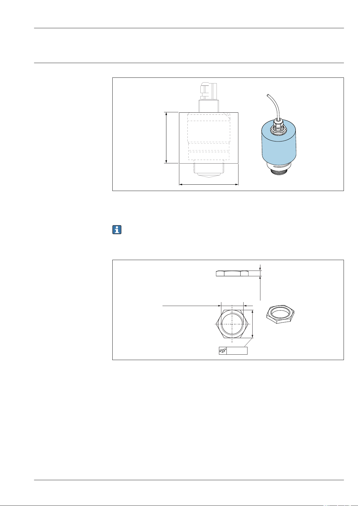
21 Dimensions of weather protection cover, engineering unit: mm (in)
A0028181
Werkstoff: PVDF
The weather protection cover is available as an accessory; order number 52025686.
The sensor is not completely covered.
Securing nut G 1-1/2"
22 Dimensions of securing nut, engineering unit: mm (in)
Suitable for use with devices with G 1-1/2" and MNPT 1-1/2" process connection.
Material: PC
Order number: 52014146
A0028849
Endress+Hauser 31
Page 32
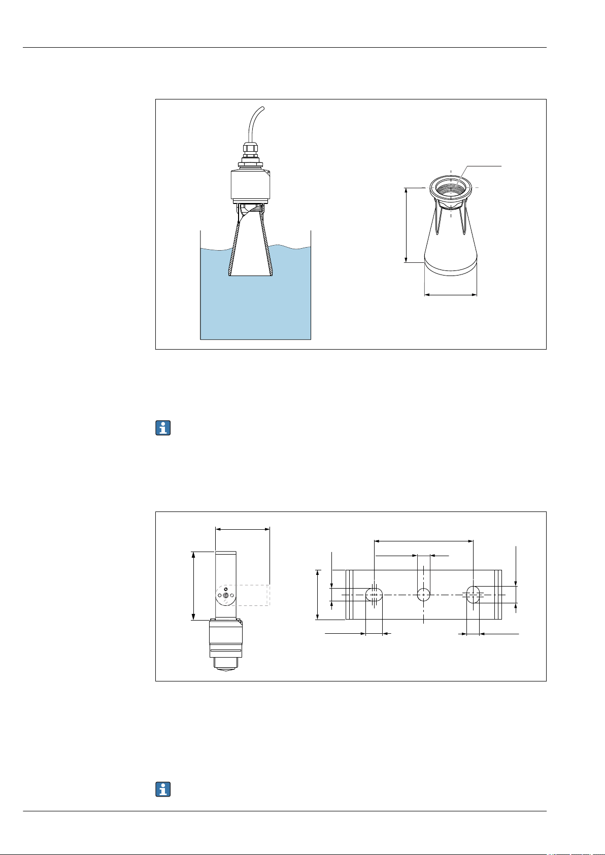
Flooding protection tube 40 mm (1.5 in) antenna, metallized PBT-PC
!89 (3,5)
152 (5,98)
G 1-1/2"
117.5 (4.63)
92.5 (3.64)
70 (2.76)
!9 (0.35)
12 (0.47) 9 (0.35)
12 (0.47)
9 (0.35)
35 (1.38)
Micropilot FMR10
For use with devices in product structure, feature 100 "Process connection on front", option WFE
"Thread ISO228 G1-1/2".
Material: PBT-PC, metallized
The flooding protection tube can be ordered with the device. Product structure, feature 620
"Accessory enclosed", option R7 "Flooding protection tube, metallized PBT-PC suitable for
40 mm (1.5 in) antenna with G1-1/2" process connection on front", extended measuring range
8 m (26.25 ft) in liquids.
Alternatively available as an accessory; order number 71325090.
Mounting bracket, adjustable
A0028418
23 Dimensions of mounting bracket, engineering unit: mm (in)
Consists of:
• Mounting bracket: 316 (1.4404)
• Angle bracket: 316L (1.4404)
The mounting bracket is available as an accessory; order number 71325079.
• Screws: A4
• Retaining rings: A4
32 Endress+Hauser
A0028861
Page 33

Micropilot FMR10
Additional accessories
For additional suitable accessories, see Technical Information TI01267F (FMR20)
Endress+Hauser 33
Page 34

Micropilot FMR10
Communication-specific accessories
System components
Accessories Description
Fieldgate FXA320 Gateway for remote monitoring of field devices with 4 to 20 mA and digital output
signal
For details, see Technical Information TI00025S and Operating Instructions
BA00053S
Accessories Description
RMA42 Digital process transmitter for monitoring and visualizing analog measured values
For details, see Technical InformationTI00150R and Operating Instructions
BA00287R
RIA452 Digital process meter RIA452, in panel mounted housing for monitoring and
displaying analog measured values, batch, pump control functions and can be used
as a preset counter and for measuring flow
For details, see Technical Information TI113R nd Operating Instructions
BA00254R
HAW562 Surge arrester for DIN rail according to IEC 60715, used to protect electronic
components from being destroyed by overvoltage.
For details, see Technical Information TI01012K
34 Endress+Hauser
Page 35

Micropilot FMR10
Supplementary documentation
The following document types are available in the Download Area of the Endress+Hauser Internet
site: www.endress.com → Download:
Standard documentation
Device Document type Document code
FMR10 Brief Operating Instructions KA01247F
Device Document type Document code
FMR10 Operating Instructions BA01577F
Endress+Hauser 35
Page 36

*71356673*
71356673
www.addresses.endress.com
 Loading...