

Page 1
TI01403F/00/EN/02.19
71441084
2019-06-28
Products
Solutions Services
Technical Information
Liquiphant FTL51B
Vibronic
Limit switch for liquids
Application
• Point level switch for minimum or maximum detection in tanks, vessels and pipes
with all kinds of liquids, even in hazardous areas
• Process temperature range: –50 to +150 °C (–58 to +302 °F)
• Pressures up to 100 bar (1 450 psi)
• Viscosities up to 10 000 mPa⋅s
• Ideal substitute for float switches, as reliable function is not affected by flow,
turbulence, bubbles, foam, vibration, solids content or buildup.
• Extension pipe up to 6 m (20 ft)
Advantages
• Approved for safety systems with functional safety requirements up to SIL2/SIL3
in accordance with IEC 61508
• Quick and cost-effective commissioning, as no adjustment required
• Design in accordance with ASME B31.3 and CRN approval
• No mechanically moving parts: no maintenance, no wear, and a long operating life
• Functional safety: monitoring of oscillation frequency of tuning fork
• RFID TAG - easy measuring point identification and easier data access
• Functional testing by means of test button on electronic insert
• Heartbeat Technology via free iOS/Android SmartBlue app
• Measuring device with Bluetooth® wireless technology
Page 2

Table of contents
Liquiphant FTL51B
About this document ........................ 4
Symbols ................................... 4
Function and system design ................... 5
point level detection ........................... 5
Measuring principle ........................... 5
Measuring system ............................ 5
Dependability ............................... 5
Input ..................................... 6
Measured variable ............................ 6
Measuring range ............................. 6
Output ................................... 6
Output and input variants ........................ 6
Output signal ................................ 6
Ex connection data ............................ 7
2-wire AC (electronic insert FEL61) ............. 8
Supply voltage ............................... 8
Power consumption ............................ 8
Current consumption ........................... 8
Power output and load current ..................... 8
Behavior of output signal ........................ 8
Terminal assignment ........................... 8
Behavior of switch output and signaling .............. 9
PFM output (electronic insert FEL67) ........... 14
Supply voltage .............................. 14
Power consumption ........................... 14
Behavior of output signal ....................... 14
Terminal assignment .......................... 15
Connection cable ............................. 15
Behavior of switch output and signaling ............. 16
2-wire NAMUR > 2.2 mA/< 1.0 mA (electronic
insert FEL68) ............................. 16
Supply voltage .............................. 16
Power consumption ........................... 16
Behavior of output signal ....................... 16
Terminal assignment .......................... 17
Behavior of switch output and signaling ............. 17
Bluetooth module and Heartbeat Technology .... 18
Bluetooth module VU121 (optional) ................ 18
Heartbeat Technology ......................... 18
Functions .................................. 18
Technical data .............................. 19
LED module VU120 (optional) ................ 19
Supply voltage .............................. 19
Power consumption ........................... 19
Current consumption .......................... 19
3-wire DC-PNP (electronic insert FEL62) ......... 9
Supply voltage ............................... 9
Power consumption ............................ 9
Current consumption ........................... 9
Load current ................................. 9
Capacitance load .............................. 9
Residual current .............................. 9
Residual voltage .............................. 9
Behavior of output signal ....................... 10
Terminal assignment .......................... 10
Behavior of switch output and signaling ............. 10
Universal current connection with relay output
(electronic insert FEL64) .................... 11
Supply voltage .............................. 11
Power consumption ........................... 11
Connectable load ............................. 11
Behavior of output signal ....................... 11
Terminal assignment .......................... 12
Behavior of switch output and signaling ............. 12
DC connection, relay output (electronic insert
FEL64 DC) ................................ 13
Supply voltage .............................. 13
Power consumption ........................... 13
Connectable load ............................. 13
Behavior of output signal ....................... 13
Terminal assignment .......................... 13
Behavior of switch output and signaling ............. 14
Performance characteristics .................. 20
Reference operating conditions ................... 20
Maximum measured error ...................... 20
Hysteresis ................................. 20
Non-repeatability ............................ 20
Influence of the process temperature ............... 20
Influence of the process pressure .................. 20
Influence of the density of the process medium (at room
temperature and normal pressure) ................. 21
Installation ............................... 22
Mounting location, orientation ................... 22
Installation instructions ........................ 22
Taking marking into account ..................... 24
Sliding sleeves .............................. 24
Aligning the cable entry ........................ 24
Special mounting instructions .................... 25
Environment .............................. 26
Ambient temperature range ..................... 26
Storage temperature .......................... 27
Humidity .................................. 27
Operating altitude ............................ 27
Climate class ............................... 27
Degree of protection .......................... 27
Vibration resistance .......................... 27
Shock resistance ............................. 27
Mechanical load ............................. 27
Electromagnetic compatibility .................... 27
2 Endress+Hauser
Page 3

Liquiphant FTL51B
Process .................................. 28
Process temperature range ...................... 28
Thermal shock .............................. 28
Process pressure range ........................ 28
Test pressure ............................... 28
Density ................................... 29
Pressure tightness ........................... 29
Mechanical construction .................... 30
Design, dimensions ........................... 30
Dimensions ................................ 31
Weight ................................... 38
Materials ................................. 39
Surface roughness ........................... 39
Operability ............................... 40
Operating concept ............................ 40
Elements on the electronic insert .................. 40
Terminals ................................. 40
Local operation ............................. 40
Local display ................................ 41
Remote interrogation ......................... 42
Diagnostic information ........................ 42
Certificates and approvals ................... 43
CE mark .................................. 43
RCM-Tick marking ............................ 43
Ex approval ................................ 43
Overfill protection ............................ 43
Functional safety ............................ 43
Marine approvals ............................ 44
Radio approval .............................. 44
CRN approval ............................... 44
Inspection certificates ......................... 44
Pressure Equipment Directive .................... 44
Process seal as per ANSI/ISA 12.27.01 .............. 44
China RoHS symbol ........................... 45
RoHS ..................................... 45
Additional certification ......................... 45
ASME B 31.3 ............................... 45
Ordering information ....................... 45
TAG ..................................... 45
Application packages ....................... 46
Heartbeat Technology ......................... 46
Accessories ............................... 46
Device-specific accessories ...................... 46
Supplementary documentation ............... 52
Special documentation ......................... 52
Supplementary device-dependent documentation ....... 52
Registered trademarks ...................... 52
Endress+Hauser 3
Page 4
About this document
DANGER
WARNING
CAUTION
NOTICE
A
1.
-
.
Symbols Safety symbols
This symbol alerts you to a dangerous situation. Failure to avoid this situation will result in serious or
fatal injury.
This symbol alerts you to a dangerous situation. Failure to avoid this situation can result in serious or
fatal injury.
This symbol alerts you to a dangerous situation. Failure to avoid this situation can result in minor or
medium injury.
This symbol contains information on procedures and other facts which do not result in personal
injury.
Electrical symbols
Ground connection
Grounded clamp, which is grounded via a grounding system.
Protective earth (PE)
Ground terminals, which must be grounded prior to establishing any other connections. The ground
terminals are located on the inside and outside of the device.
Liquiphant FTL51B
Symbols for certain types of information
Permitted
Procedures, processes or actions that are permitted.
Forbidden
Procedures, processes or actions that are forbidden.
Tip
Indicates additional information
Reference to documentation
Reference to another section
, 2., 3. Series of steps
Symbols in graphics
A, B, C ... View
1, 2, 3 ... Item numbers
Hazardous area
Safe area (non-hazardous area)
4 Endress+Hauser
Page 5
Liquiphant FTL51B
A B
Function and system design
point level detection
Measuring principle
Measuring system
Maximum or minimum detection for liquids in tanks or pipes in all industries. Suitable for leakage
monitoring, dry-running protection, pump protection or overfill protection, for example .
Specific versions are suitable for use in hazardous areas.
The point level switch differentiates between the "covered" and "not covered" conditions.
Depending on the MIN (minimum detection) or MAX (maximum detection) modes, there are two
possibilities in each case: OK status and demand mode
OK status
• In MIN mode, the fork is covered, e. g. pump protection
• In MAX mode, the fork is not covered e. g. overfill protection
Demand mode
• In MIN mode, the fork is not covered e. g. pump protection
• In MAX mode, the fork is covered e. g. overfill protection
The sensor's tuning fork vibrates at its intrinsic frequency. As soon as the liquid covers the tuning
fork, the vibration resistance decreases. The change in frequency causes the point level switch to
switch.
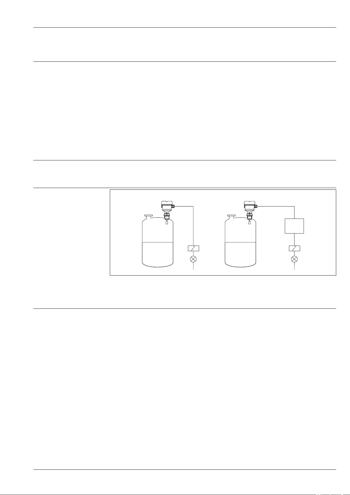
1 Example of a measuring system
A Device for direct connection of a load
B Device for connection to a separate switching unit or PLC
Dependability Device-specific IT security
The device settings and the diagnostic data can be read out via Bluetooth. Device settings cannot be
changed via Bluetooth.
A0035308
Endress+Hauser 5
Page 6

Input
Liquiphant FTL51B
Measured variable
Measuring range
Level (point level), MAX or MIN safety
Depends on the installation location and the pipe extension ordered
Maximum sensor length 6 m (20 ft)
Output
Output and input variants Electronic inserts
2-wire AC (FEL61)
• Two-wire AC version
• Switches the load directly into the power supply circuit via an electronic switch.
3-wire DC-PNP (FEL62)
• Three-wire DC version
• Switches the load via the transistor (PNP) and separate connection, e. g. in conjunction with
programmable logical controllers (PLC)
• Ambient temperature –60 °C (–76 °F), optionally available for order
Low-temperature electronic inserts are marked LT.
Universal current connection, relay output (FEL64)
• Switches the loads via 2 potential-free changeover contacts
• Ambient temperature –60 °C (–76 °F), optionally available for order
Low-temperature electronic inserts are marked LT.
Direct current connection, relay output (FEL64DC)
• Switches the load via 2 potential-free changeover contacts
• Ambient temperature –60 °C (–76 °F), optionally available for order
Low-temperature electronic inserts are marked LT.
PFM output (FEL67)
• For separate switching device (Nivotester FTL325P, FTL375P)
• PFM signal transmission; current pulses are superimposed on the power supply along the two-wire
cabling
• Ambient temperature –52 °C (–62 °F), optionally available for order
The low-temperature electronic inserts are marked LT
2-wire NAMUR > 2.2 mA/< 1.0 mA (FEL68)
• For separate switching device, e. g. Nivotester FTL325N
• Signal transmission H-L edge 2.2 to 3.8/0.4 to 1.0 mA as per IEC 60917-5-6 (NAMUR) on two-
wire cable
• Ambient temperature –52 °C (–62 °F), optionally available for order
Low-temperature electronic inserts are marked LT.
2-wire density (FEL60D) for density measurement
Connection to Density Computer FML621
For more information, see the Technical Information for density measuring technology.
Output signal Switch output
Preset switching times can be ordered. The following ranges can be ordered for point level switches
without communication (AC two-wire, relays, DC-PNP, PFM, NAMUR):
• 0.5 seconds when the fork is covered and 1.0 seconds when it is uncovered (factory setting)
• 0.25 seconds when the fork is covered and 0.25 seconds when it is uncovered (fastest setting)
• 1.5 seconds when the fork is covered and 1.5 seconds when it is uncovered
• 5 seconds when the fork is covered and 5 seconds when it is uncovered
COM interface
For connecting to modules VU120 or VU121 (no modifying effect)
6 Endress+Hauser
Page 7

Liquiphant FTL51B
Bluetooth® wireless technology (optional)
The device has a Bluetooth® wireless technology interface. Device data and diagnostic data can be
read out using the free "SmartBlue" app.
Ex connection data
See safety instructions (XA): All data relating to explosion protection are provided in separate Ex
documentation and are available from the Downloads Area of the Endress+Hauser-website. The Ex
documentation is supplied as standard with all Ex devices.
Endress+Hauser 7
Page 8
Liquiphant FTL51B
!
>0,5
COM
NL1
1
2
MIN
MAX
>0,7
U 19...253 V AC
I max: 350 mA
~
~
1 A
L1 NPE
K
1 2
2-wire AC (electronic insert FEL61)
• Two-wire AC version
• Switches the load directly into the power supply circuit via an electronic switch; always connect in
series with a load.
• Functional testing without level change
A functional test can be performed on the device using the test button on the electronic insert.
Supply voltage
Power consumption
Current consumption
Power output and load current
Behavior of output signal
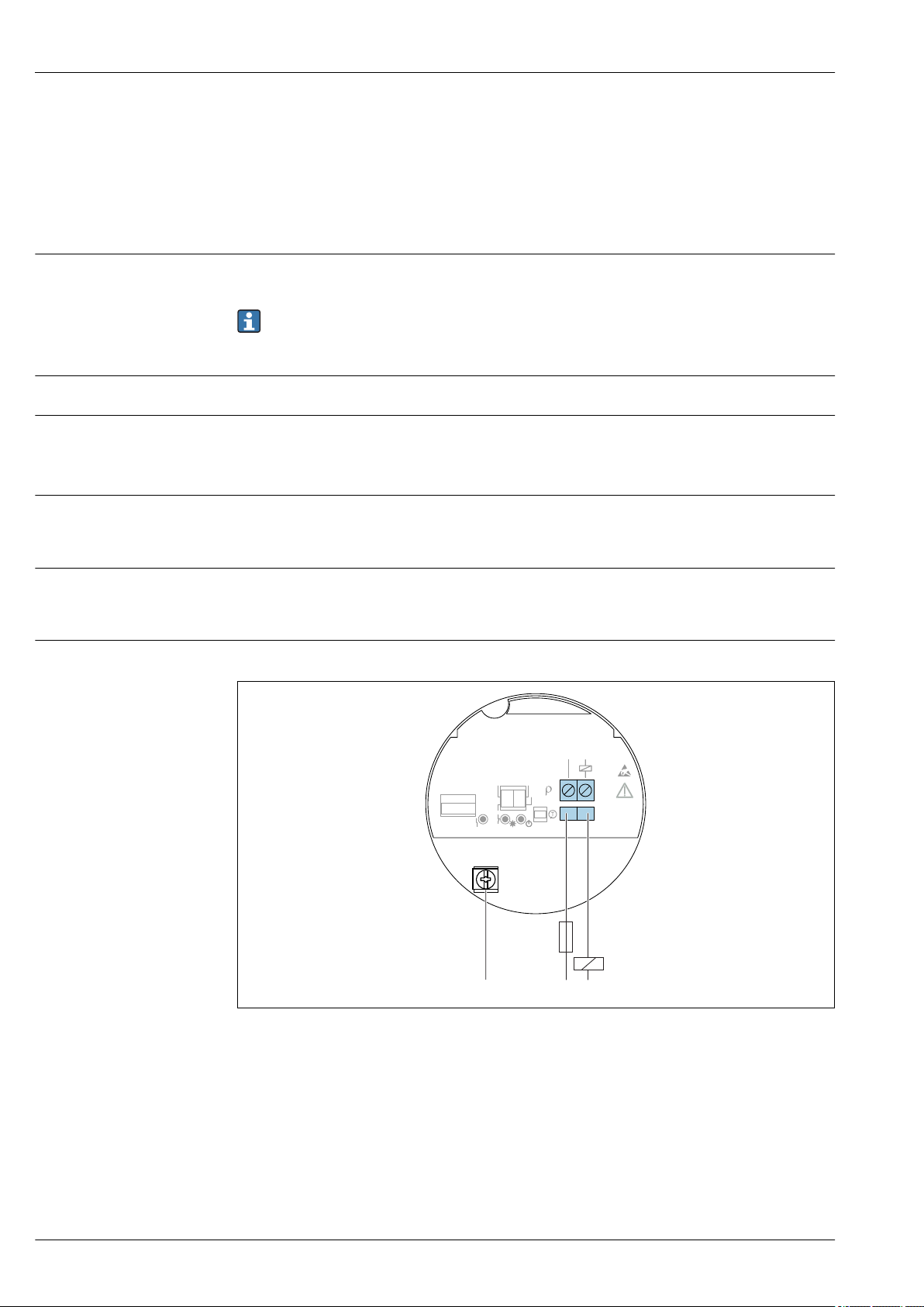
Terminal assignment
U = 19 to 253 V
AC
Residual voltage when switched through: maximum 12 V
Pay attention to the following as per IEC/EN61010-1: Provide a suitable circuit breaker for the
device, and limit the current to 1 A, e. g. by installing a 1 A fuse (slow-blow) in the line (not the
neutral wire) of the supply circuit.
P ≤ 2 VA
Residual current when blocked: I ≤ 3.8 mA
The red LED flashes in the event of an overload or short-circuit. Check for an overload or shortcircuit every 5 seconds. The test is deactivated after 60 seconds.
• Max 89 VA/253 V (350 mA); max 8.4 VA/24 V (350 mA)
• Min 2.5 VA/253 V (10 mA); min ≥ 0.5 VA/24 V (20 mA)
• With overload and short-circuit protection.
• OK status: load on (switched through)
• Demand mode: load off (blocked)
• Alarm: load off (blocked)
Always connect an external load. The electronic insert has integrated short-circuit protection.
A0036060
2 2-wire AC, electronic insert FEL61
8 Endress+Hauser
Page 9
Liquiphant FTL51B
MAX
RD YE GN
MIN
K
K
K
K
K
(N)
(N)
(N)
(N)
(N)
I
L
I
L
<3.8 mA
<3.8 mA
<3.8 mA
2
2
2
2
2
1
1
1
1
1
L1
L1
L1
L1
L1
ΔU
ΔU
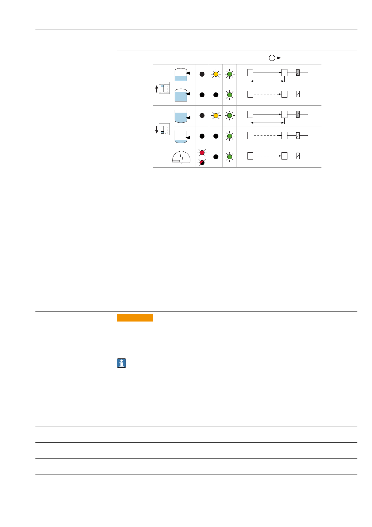
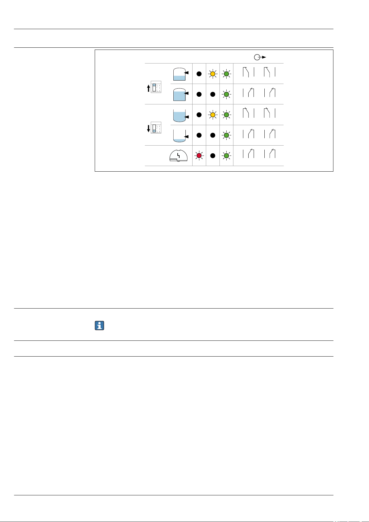
Behavior of switch output and signaling
A0031901
3 Behavior of switch output and signaling, electronic insert FEL61
MAXDIP switch for setting MAX safety mode
MIN DIP switch for setting MIN safety mode
RD LED, red, for warning or alarm
YE LED, yellow, switch status
GN LED, green, operational status, device on
ILLoad current switched through
Supply voltage
Power consumption
Current consumption
Load current
Capacitance load
Residual current
Residual voltage
3-wire DC-PNP (electronic insert FEL62)
• Three-wire DC version
• Preferably in conjunction with programmable logic controllers (PLC), DI modules as per
EN 61131-2. Positive signal at switch output of electronics module (PNP)
• Functional testing without level change
A functional test can be performed on the device using the test button on the electronic insert or
using the test magnet with the housing closed.
WARNING
L
Failure to use the prescribed power unit.
Risk of fatal injury due to electric shock!
The FEL62 may only be powered by devices with safe galvanic isolation, as per IEC 61010-1.
‣
U =10 to 55 V
Pay attention to the following as per IEC/EN61010-1: Provide a suitable circuit breaker for the
device, and limit the current to 500 mA, e. g. by installing a 0.5 A fuse (slow-blow) in the line
(not the neutral wire) of the supply circuit.
P ≤ 0.5 W
I ≤ 10 mA (without load)
The red LED flashes in the event of an overload or short-circuit.
I ≤ 350 mA with overload and short-circuit protection
C ≤ 0.5 µF at 55 V, C ≤ 1.0 µF at 24 V
I < 100 µA (with transistor blocked)
U < 3 V (with transistor switched through)
DC
Endress+Hauser 9
Page 10
Liquiphant FTL51B
!
U = 10...55 V DC
I max: 350 mA
1
3
L-L+
COM
MIN
MAX
>0,7
>0,5
1
3
0.5 A
L+ L-
I 350 mA
max
U 55 V
max
K
K
I
L
PE
4
3
1
2
1
3
4
M12
1 2 3
B
A
L+ L-
K
MAX
RD YE GN
MIN
K
K
K
(L–)
(L–)
(L–)
I
L
<100 µA
I
L
3
3
3
1
1
1
L+
L+
L+
ΔU
ΔU
K
(L–)
<100 µA
3
1
L+
(L–)
<100 µA
3
1
L+
K
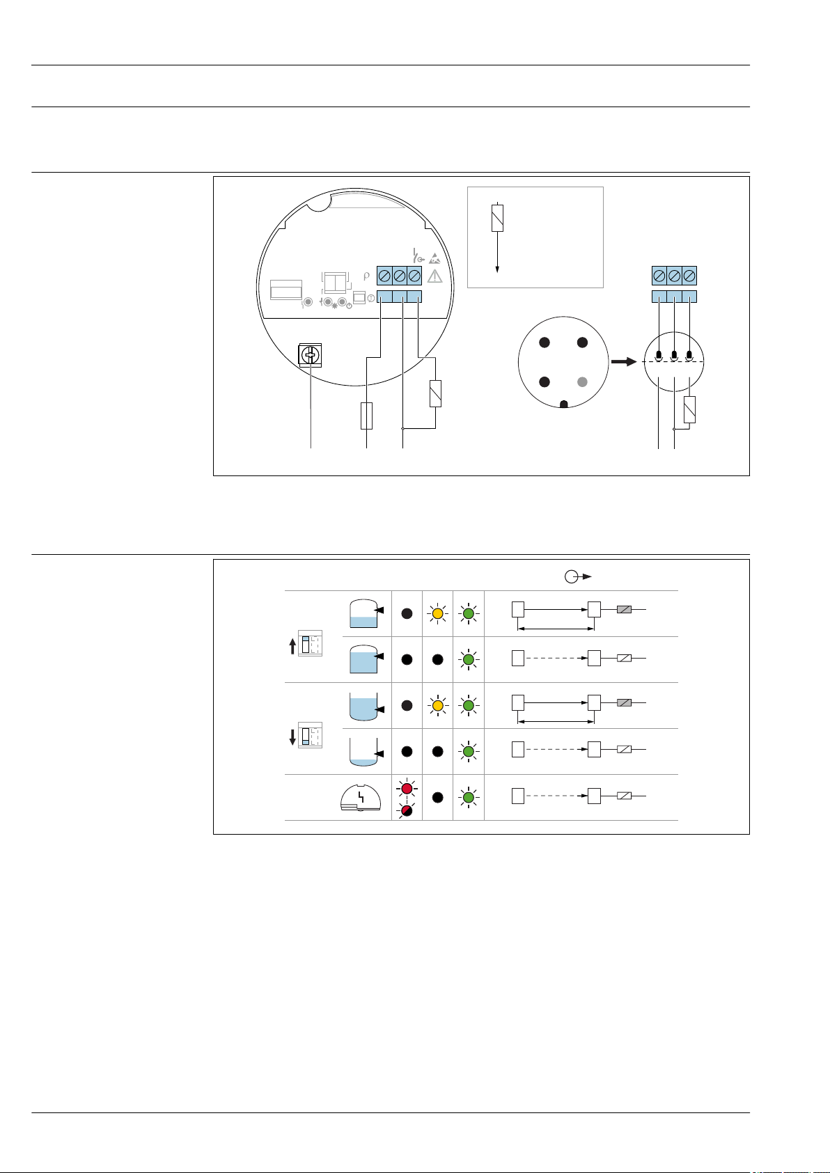
Behavior of output signal
Terminal assignment
• OK status: switched through
• Demand mode: blocked
• Alarm: blocked
A0036061
4 3-wire DC-PNP, electronic insert FEL62
A Connection wiring with terminals
B Connection wiring with M12 connector in housing as per EN61131-2 standard
Behavior of switch output and signaling
5 Behavior of switch output and signaling, electronic insert FEL62
MAXDIP switch for setting MAX safety mode
MIN DIP switch for setting MIN safety mode
10 Endress+Hauser
RD LED, red, for warning or alarm
YE LED, yellow, switch status
GN LED, green, operational status, device on
ILLoad current switched through
A0033508
Page 11

Liquiphant FTL51B
Universal current connection with relay output (electronic insert FEL64)
• Switches the loads via 2 potential-free changeover contacts
• Two galvanically isolated change-over contacts (DPDT), both change-over contacts switch
simultaneously
• Functional testing without level change. A functional test can be performed on the device using
the test button on the electronic insert or using the test magnet with the housing closed.
WARNING
L
In the event of an error, the electronic insert can exceed the limit temperature for touchable
surfaces, resulting in a risk of burns.
Do not touch the electronics in the event of an error!
‣
Supply voltage
Power consumption
Connectable load
Behavior of output signal
U = 19 to 253 VAC/19 to 55 V
Pay attention to the following as per IEC/EN61010-1: Provide a suitable circuit breaker for the
device, and limit the current to 500 mA, e. g. by installing a 0.5 A fuse (slow-blow) in the line
(not the neutral wire) of the supply circuit.
P < 25 VA,< 1.3 W
Loads switched via 2 potential-free changeover contacts (DPDT)
• IAC ≤ 6 A (Ex de 4 A), U~ ≤ AC 253 V; P~ ≤ 1 500 VA, cos φ = 1, P~ ≤ 750 VA, cos φ > 0.7
• IDC ≤ 6 A (Ex de 4 A) to DC 30 V, I DC ≤ 0.2 A to 125 V
According to IEC 61010: the sum of the voltages of the relay outputs and power supply ≤ 300 V
Preferably use electronic insert FEL62 DC PNP for low DC current loads, e. g. connection to a PLC.
Relay contact material: silver/nickel AgNi 90/10
When connecting a device with high inductance, fit a spark suppressor to protect the relay contact.
Depending on the connected load, a fine-wire fuse protects the relay contact in the event of a shortcircuit.
Both relay contacts switch simultaneously.
• OK status: relay energized
• Demand mode: relay de-energized
• Alarm: relay de-energized
DC
Endress+Hauser 11
Page 12
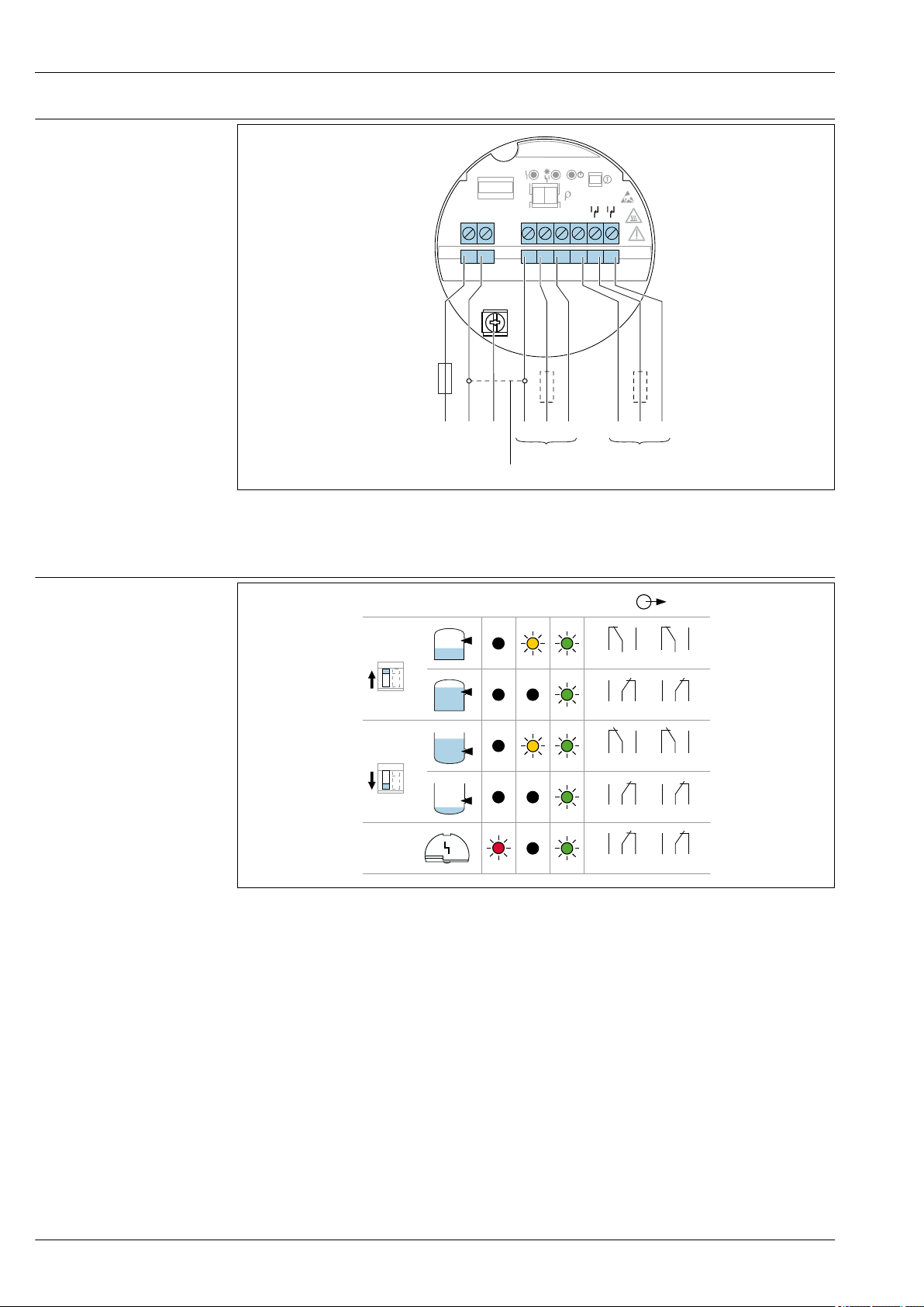
Terminal assignment
L1 N
4
3 5
876
U = 19...55 V DC
U 19...253 V AC
~
~
!
0.5 A
1
2 2
L1
L+
NO NONC NCC CNL-PE
1 2 3 64 75 8
MIN
>0,7
MAX
>0,5
COM
3 54
3 54
6 87
6 87
3 54
33554
4
6 87
66887
7
MAX
RD YE GN
MIN
Liquiphant FTL51B
A0036062
6 Universal current connection with relay output, electronic insert FEL64
1 When bridged, the relay output works using NPN logic.
2 Connectable load
Behavior of switch output and signaling
A0033513
7 Behavior of switch output and signaling, electronic insert FEL64
MAXDIP switch for setting MAX safety mode
MIN DIP switch for setting MIN safety mode
RD LED, red, for alarm
YE LED, yellow, switch status
GN LED, green, operational status, device on
12 Endress+Hauser
Page 13
Liquiphant FTL51B
L1 N
4
3 5
876
U = 9...20 V DC
!
0.5 A
1
2 2
L1
L+
NO NONC NCC CNL-PE
1 2 3 64 75 8
MIN
>0,7
MAX
>0,5
COM
DC connection, relay output (electronic insert FEL64 DC)
• Switches the loads via 2 potential-free changeover contacts
• Two galvanically isolated change-over contacts (DPDT), both change-over contacts switch
simultaneously
• Functional testing without level change. Functional testing of the entire device can be performed
using the test button on the electronic insert or with the test magnet with the housing closed.
Supply voltage
Power consumption
Connectable load
Behavior of output signal
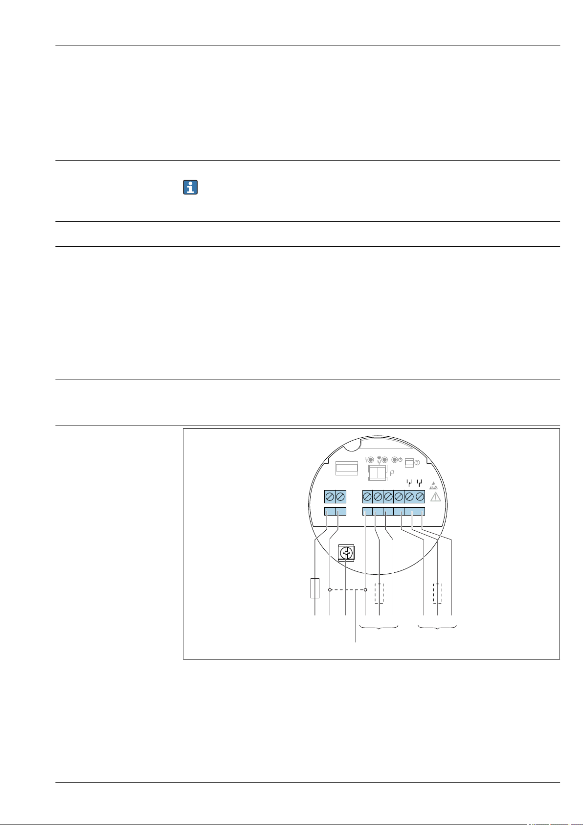
Terminal assignment
U = 9 to 20 V
DC
Pay attention to the following as per IEC/EN61010-1: Provide a suitable circuit breaker for the
device, and limit the current to 500 mA, e. g. by installing a 0.5 A fuse (slow-blow) in the power
circuit.
P < 1.0 W
Loads switched via 2 potential-free changeover contacts (DPDT)
• IAC ≤ 6 A (Ex de 4 A), U~ ≤ AC 253 V; P~ ≤ 1 500 VA, cos φ = 1, P~ ≤ 750 VA, cos φ > 0.7
• IDC ≤ 6 A (Ex de 4 A) to DC 30 V, I DC ≤ 0.2 A to 125 V
According to IEC 61010: the sum of the voltages of the relay outputs and power supply ≤ 300 V
Preferably use electronic insert FEL62 DC PNP for low DC current loads, e. g. connection to a PLC.
Relay contact material: silver/nickel AgNi 90/10
When connecting a device with high inductance, fit a spark suppressor to protect the relay contact.
Depending on the connected load, a fine-wire fuse protects the relay contact in the event of a shortcircuit.
• OK status: relay energized
• Demand mode: relay de-energized
• Alarm: relay de-energized
Endress+Hauser 13
A0037685
8 DC connection with relay output, electronic insert FEL64 DC
1 When bridged, the relay output works using NPN logic.
2 Connectable load
Page 14
Behavior of switch output
3 54
3 54
6 87
6 87
3 54
33554
4
6 87
66887
7
MAX
RD YE GN
MIN
and signaling
Liquiphant FTL51B
A0033513
9 Behavior of switch output and signaling, electronic insert FEL64 DC
MAXDIP switch for setting MAX safety mode
MIN DIP switch for setting MIN safety mode
RD LED, red, for alarm
YE LED, yellow, switch status
GN LED, green, operational status, device on
Supply voltage
Power consumption
Behavior of output signal
PFM output (electronic insert FEL67)
• For connecting to the Nivotester FTL325P and FTL375P switching units from Endress+Hauser
• PFM signal transmission; pulse frequency modulation, superimposed on the power supply along
the two-wire cabling
• Functional testing without level change:
• A functional test can be performed on the device using the test button on the electronic insert.
• The functional test can also be prompted by disconnecting the supply voltage or triggered
directly by the Nivotester FTL325P and FTL375P switching unit.
U = 9.5 to 12.5 V
Pay attention to the following as per IEC/EN61010-1: Provide a suitable circuit breaker for the
device.
P ≤ 150 mW with Nivotester FTL325P or FTL375P
• OK status: MAX mode 150 Hz, MIN mode 50 Hz
• Demand mode: MAX mode 50 Hz, MIN mode 150 Hz
• Alarm: MAX/MIN mode 0 Hz
DC
14 Endress+Hauser
Page 15
Liquiphant FTL51B
>0,5
COM
MIN
MAX
>0,7
– +
1
2
L- L+
!
!
7
33
37
d4
z4
8
34
38
d2
z2
z6 d6
.
-
1 2
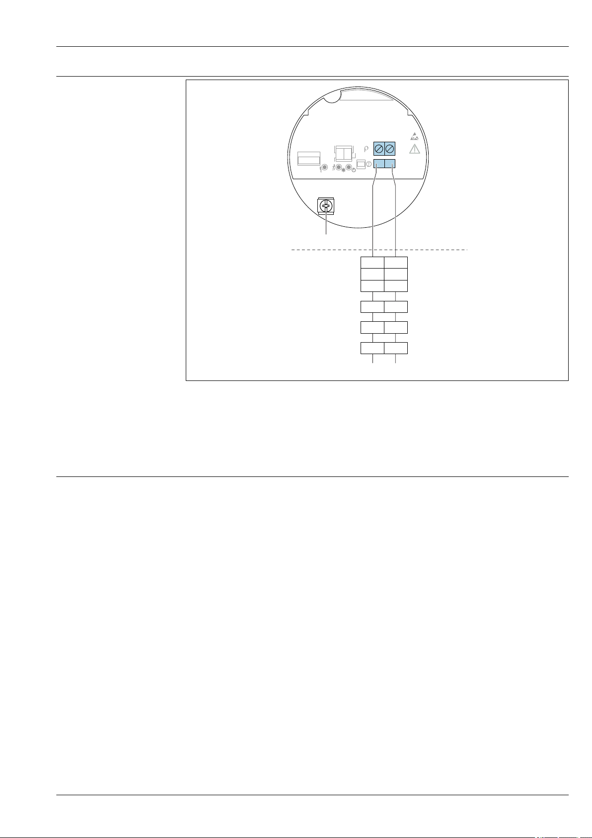
Terminal assignment
Connection cable
A0036065
10 PFM output, electronic insert FEL67
7/ 8: Nivotester FTL325P 1 CH, FTL325P 3 CH input 1
33/ 34: Nivotester FTL325P 3 CH input 2
37/ 38: NivotesterFTL325P 3 CH input 3
d4/ d2: Nivotester FTL375P input 1
z4/ z2: Nivotester FTL375P input 2
z6/ d6: Nivotester FTL375P input 3
• Maximum cable resistance: 25 Ω per core
• Maximum cable capacitance: < 100 nF
• Maximum cable length: 1 000 m (3 281 ft)
Endress+Hauser 15
Page 16
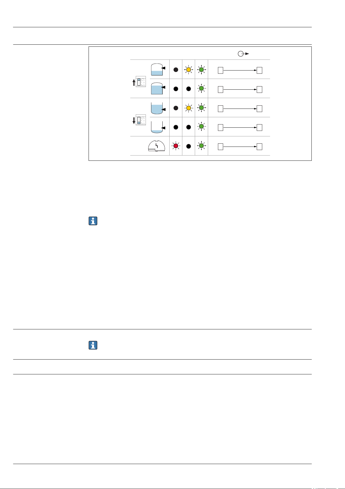
Behavior of switch output
MAX
RD YE GN
MIN
1
1
1
1
1
2
2
2
2
2
L+
L+
L+
L+
L+
150 Hz
50 Hz
50 Hz
150 Hz
0 Hz
L-
L-
L-
L-
L-
and signaling
Liquiphant FTL51B
A0037696
11 Switching behaviour and signaling, electronic insert FEL67
MAXDIP switch for setting MAX safety mode
MIN DIP switch for setting MIN safety mode
RD LED, red, for alarm
YE LED, yellow, switch status
GN LED, green, operational status, device on
Supply voltage
Power consumption
Behavior of output signal
The MAX/MIN switch must be set in accordance with the application. Only then is it possible to
perform the functional test correctly.
2-wire NAMUR > 2.2 mA/< 1.0 mA (electronic insert FEL68)
• For connecting to isolating amplifier as per NAMUR (IEC 60947-5-6), e. g. the Nivotester
FTL325N from Endress+Hauser
• Signal transmission H-L edge 2.2 to 3.8 mA/ 0.4 to 3.8 mA as per IEC 60947-5-6 (NAMUR) on
two-wire cable
• Functional testing without level change. A functional test can be performed on the device using
the test button on the electronic insert or using the test magnet with the housing closed.
The functional test can also be triggered by interrupting the supply voltage or activated directly
from the Nivotester FTL325N.
U = 8.2 V
NAMUR IEC 60947-5-6
• OK status: output current 2.2 to 3.8 mA
• Demand mode: output current 0.4 to 1.0 mA
• Alarm: output current 0.4 to 1.0 mA
DC
Pay attention to the following as per IEC/EN61010-1: Provide a suitable circuit breaker for the
device.
16 Endress+Hauser
Page 17

Liquiphant FTL51B
>0,5
COM
– +
MIN
MAX
>0,7
IEC 60947-5-6
8,2 V DC NAMUR
1
2
L- L+
.
-
1 2
!
!
MAX
RD YE GN
MIN
1
1
1
1
1
2
2
2
2
2
L+
L+
L+
L+
L+
2.2...3.8 mA
0.4...1.0 mA
2.2...3.8 mA
0.4...1.0 mA
< 1.0 mA
L-
L-
L-
L-
L-
Terminal assignment
A0036066
12 2-wire NAMUR > 2.2 mA/< 1.0 mA, electronic insert FEL68
Behavior of switch output and signaling
A0037694
13 Behavior of switch output and signaling, electronic insert FEL68
MAXDIP switch for setting MAX safety mode
MIN DIP switch for setting MIN safety mode
RD LED, red, for alarm
YE LED, yellow, switch status
GN LED, green, operational status, device on
When using the device with the electronic insert FEL68 (2-wire NAMUR), the Bluetooth
module must be ordered separately, including the required battery.
Product Configurator, order code for "Accessory mounted", option NG "Prepared for Heartbeat
Verification + Monitoring + Bluetooth".
Endress+Hauser 17
Page 18

Bluetooth module VU121
Contains
FCC ID:
IC:
(optional)
Liquiphant FTL51B
Bluetooth module and Heartbeat Technology
A0039257
14 Bluetooth module VU121
• The Bluetooth module can be connected via the COM interface to the following electronic inserts:
FEL61, FEL62, FEL64, FEL64 DC, FEL67, FEL68 (2-wire NAMUR).
• The Bluetooth module with battery is suitable for use in hazardous areas.
• For energy-related reasons, the Bluetooth module requires a special battery when operated with
the 2-wire NAMUR electronics.
When using the device with the electronic insert FEL68 (2-wire NAMUR), the Bluetooth
module must be ordered separately, including the required battery.
Product Configurator, order code for "Accessory mounted", option NG "Prepared for Heartbeat
Verification + Monitoring + Bluetooth".
Batteries
The battery is categorized as dangerous goods when transported by air and may not be installed
in the device when shipped.
Replacement batteries can be purchased from a specialist retailer. Only the following types of
AA 3.6 V lithium batteries made by the manufacturers listed below are suitable as replacement
batteries:
• SAFT LS14500
• TADIRAN SL-360/s
• XENOENERGY XL-060F
Heartbeat Technology Heartbeat Technology module
Heartbeat Diagnostics
Continuously monitors and evaluates the device status and process conditions. Generates diagnostic
messages when certain events occur and provides troubleshooting measures in accordance with
NAMUR NE 107.
Heartbeat Verification
Performs a verification of the current device status upon request and generates a Heartbeat
Technology verification report showing the result of the verification.
Heartbeat Monitoring
Continuously provides device and/or process data for an external system. Analysis of this data forms
the basis for process optimization and predictive maintenance.
Functions
• Connection via COM interface: Bluetooth module for device diagnostics via a smartphone app or
tablet app
• Display the battery status via app when used with electronic insert FEL68 (NAMUR)
• User guidance (wizard) for SIL/WHG proof testing
• Visible in the livelist 10 seconds after the Bluetooth search commences
• Data can be read from the Bluetooth module 60 seconds after the supply voltage has been
switched on.
• Display of the current vibration frequency and the switching state of the device
The yellow LED flashes when the Bluetooth module is connected to another Bluetooth device, e.g. a
cellular phone.
18 Endress+Hauser
Page 19

Liquiphant FTL51B
Technical data
• Approval: intrinsically safe Ex ia, IS or ec/ic
• NAMUR electronics (electronic insert FEL68):
For energy-related reasons, the Bluetooth module VU121 requires a special battery when operated
with the 2-wire NAMUR electronics. The service life of the Bluetooth module without replacing
the battery is at least 5 years with a maximum of 60 downloads of complete datasets (at ambient
temperatures between 10 to 40 °C (50 to 104 °F)).
• Maximum free-field range 50 m (165 ft)
• Operation radius with intervisibility 10 m (33 ft) around the device
For documentation on radio approvals, see the Endress+Hauser website: www.endress.com →
Downloads.
LED module VU120 (optional)
A0039258
15 LED module
Supply voltage
Power consumption
Current consumption
The bright LED display indicates the switch status or the alarm condition and can be connected to
the following electronic inserts: FEL62, FEL64, FEL64DC
U = 12 to 55 VDC, 19 to 253 V
AC
U ≤ 0.7 W, < 6 VA
I
= 0.4 A
max
Endress+Hauser 19
Page 20

Performance characteristics
~13 (0.5)
~4 (0.16)
~12.5 (0.49)
D
A B C
D
D
Liquiphant FTL51B
Reference operating conditions
• Ambient temperature: 23 °C (73 °F)
• Process temperature: 23 °C (73 °F)
• Density (water): 1 g/cm
3
• Medium viscosity: 1 mPa⋅s
• Process pressure: ambient pressure/unpressurized
• Sensor installation: vertically from above
• Density selection switch: > 0.7 g/cm3 (SGU)
• Switch direction of sensor: uncovered to covered
Taking the switch point into consideration
Typical switch points, depending on the orientation of the point level switch
(water +23 °C (+73 °F))
16 Typical switch points. Unit of measurement mm (in)
A Installation from above
B Installation from below
C Installation from the side
D Switch point
A0037915
Maximum measured error
Hysteresis
Non-repeatability
Influence of the process temperature
Influence of the process pressure
At reference operating conditions: max. ±1 mm (0.04 in)
Typically 2.5 mm (0.1 in)
2 mm (0.08 in)
The switch point moves between +1.4 to –2.6 mm (+0.06 to –0.1 in) in the temperature range from
–50 to +150 °C (–58 to +302 °F)
The switch point moves between 0 to 2.6 mm (0 to 0.1 in) in the pressure range from
–1 to +64 bar (14.5 to 928 psi)
20 Endress+Hauser
Page 21

Liquiphant FTL51B
0.5
1 1.5 2
-8
-6
-4
-2
0
2
4
6
[in]
[g/cm!]
C
A ( )ρ
B1 A1
-0.3
-0.2
-0.2
-0.1
0
0.2
0.2
[mm]
0.1
B ( )ρ
[ ]ρ
Alloy C22
316L
Influence of the density of the process medium (at room temperature and normal pressure)
17 Switch point deviation over density
A Density switch setting (ρ) > 0.7
A1
Reference condition ρ = 1 g/cm
B Density switch setting (ρ) > 0.5
B1
Reference condition ρ = 0.7 g/cm
C Switch point deviation
3
3
A0037670
Density setting
• TK
, [mm/10 k]
typ
• ρ > 0.7: –0.2
• ρ > 0.5: –0.2
• Pressure
, [mm/10 bar]
typ
• ρ > 0.7: –0.3
• ρ > 0.5: –0.4
Endress+Hauser 21
Page 22

Mounting location,
1
> 25 (0.98)
D
> 40 (1.57)
orientation
Liquiphant FTL51B
Installation
Open the device only in a dry environment!
18 Installation in any position in a vessel, pipe or tank
1 Temperature spacer for tank with insulation and/or high process temperatures
Installation instructions Take viscosity into consideration
Low viscosity
19 Installation example for low-viscosity liquids. Unit of measurement mm (in)
D Diameter of installation socket: at least 50 mm (2.0 in)
Low viscosity, e. g. water: < 2 000 mPa⋅s
It is permitted to position the tuning fork within the installation socket.
A0037879
A0033297
High viscosity
A0037348
20 Installation example for a highly viscous liquid. Unit of measurement mm (in)
22 Endress+Hauser
Page 23

Liquiphant FTL51B
NOTICE
Highly viscous liquids may cause switching delays.
Make sure that the liquid can run off the tuning fork easily.
‣
Deburr the socket surface.
‣
High viscosity, e. g. viscous oils: < 10 000 mPa⋅s
The tuning fork must be located outside the installation socket!
Avoiding buildup
21 Installation examples for a highly viscous process medium
• Use short installation sockets to ensure that the turning fork can project freely into the vessel.
• Install preferably flush-mounted on vessels or in pipes.
• Leave sufficient distance between the buildup expected on the tank wall and the tuning fork.
Take clearance into consideration
22 Take clearance into consideration
A0033239
A0033236
Allow sufficient space outside the tank for mounting, connection and settings involving the
electronic insert.
Endress+Hauser 23
Page 24

Taking marking into account Align the tuning fork in accordance with the marking.
316L/G1
1.
2.
3
0.7 Nm
3
3.
23 Markings for aligning the tuning fork
Using the marking, the tuning fork can be aligned in such a way that medium can run off easily and
buildup is avoided.
Markings may include the following:
• material specification, thread description or circle on hexagonal nut or welding neck
• Symbol II on rear of flange or Tri-Clamp
Installing in pipes
Liquiphant FTL51B
A0039125
Sliding sleeves
Aligning the cable entry
A0034851
24 Installation in pipes
Flow velocities up to 5 m/s at a viscosity of 1 mPa⋅s and density of 1 g/cm3 (SGU)
Check the function in the event of other process medium conditions.
The flow will not be significantly impeded if the tuning fork is correctly aligned and the marking on
the adapter is pointing in the direction of flow.
The marking is visible when installed.
See the "Accessories" section.
A0037347
25 Housing with external locking screw
24 Endress+Hauser
Page 25

Liquiphant FTL51B
316L
Special mounting instructions
Support the device
A0031874
26 Support in the event of dynamic load
Support the device in the event of severe dynamic load. Maximum lateral loading capacity of the pipe
extensions and sensors: 75 Nm (55 lbf ft).
Weld-in adapter with leakage hole
A0039230
27 Weld-in adapter with leakage hole
Weld in the welding neck in such a way that the leakage hole is pointing downwards. This enables
any leaks to be detected quickly.
Endress+Hauser 25
Page 26

Environment
T
p
+150
+302
+120
+248
+90
+194
+60
+140
+30
+86
0
32
-30
-22
-60
-76
70158
60140
50122
40104
3086
20
68
1050
032
A
B
[°C]
[°C]
[°F]
[°F]
T
a
Liquiphant FTL51B
Ambient temperature range
–40 to +70 °C (–40 to +158 °F)
WARNING
L
Permitted connection voltage exceeded!
For electrical safety reasons, the maximum connection voltage for all electronic inserts at
‣
ambient temperatures below –40 °C (–40 °F) is limited to a maximum of 35 V DC.
Optional
–60 °C (–76 °F) or –52 °C (–62 °F)
In the hazardous area, the permitted ambient temperature can be limited depending on the zones
and gas groups. Pay attention to the information in the Ex documentation (XA).
The minimum permitted ambient temperature of the plastic housing is limited to –20 °C (–4 °F);
"indoor use" applies in North America.
A0037923
28 Permitted ambient temperature Ta at the housing as a function of the process temperature Tp in the vessel:
A Device without LED module; at process temperature Tp > 90°, with FEL64 and max. load current 4 A
B Device with LED module; at process temperature and FEL64 Tp > 90° max. load current 2 A
For devices with a temperature spacer, the following ambient temperatures apply across the entire
process temperature range:
A: 70 °C
B: 60 °C
Ordering information:
• Product Configurator, order code for "output", option "1"
Ambient temperature –60 °C (–76 °F), optionally available for order
• Product Configurator, order code for "output", option "2"
Ambient temperature –52 °C (–62 °F), optionally available for order.
Low-temperature electronic inserts are marked LT.
• Bluetooth module (non-Ex): –40 to +85 °C (–40 to +185 °F)
• Bluetooth module (Ex ia): –40 to +65 °C (–40 to +149 °F), T4
• LED module: –40 to +60 °C (–40 to +140 °F)
Outdoor operation in strong sunlight:
• Mount the device in the shade.
• Avoid direct sunlight, particularly in warmer climatic regions.
• Use a weather protection cover, which can be ordered as an accessory
26 Endress+Hauser
Page 27

Liquiphant FTL51B
Storage temperature
Humidity
Operating altitude
Climate class
Degree of protection
–40 to +80 °C (–40 to +176 °F)
optional: –52 °C (–62 °F), –60 °C (–76 °F)
Operate up to 100 %. Do not open in a condensing atmosphere.
As per IEC 61010-1 Ed.3:
• Up to 2 000 m (6 600 ft) above sea level
• Can be extended to 3 000 m (9 800 ft) above sea level if overvoltage protection is used
As per IEC 60068-2-38 test Z/AD
For housing with electrical connection
M20 coupling, plastic
• Single-chamber, plastic: IP66/67 NEMA type 4X
• Single-chamber and dual-chamber, aluminum: IP66/68 NEMA type 4X/6P
• Single-chamber 316L, cast: IP66/68 NEMA type 4X/6P
M20 coupling, nickel-plated brass
Single-chamber and dual-chamber, aluminum: IP66/68 NEMA type 4X/6P
M20 coupling, 316L
• Single-chamber and dual-chamber, aluminum: IP66/68 NEMA type 4X/6P
• Single-chamber 316L, cast: IP66/68 NEMA type 4X/6P
Thread M20
• Single-chamber, plastic: IP66/67 NEMA type 4X
• Single-chamber and dual-chamber, aluminum: IP66/68 NEMA type 4X/6P
• Single-chamber 316L, cast: IP66/68 NEMA type 4X/6P
Thread G ½
• Single-chamber, plastic: IP66/67 NEMA type 4X
• Single-chamber and dual-chamber, aluminum: IP66/68 NEMA type 4X/6P
• Single-chamber 316L, cast: IP66/68 NEMA type 4X/6P
Thread NPT ½
• Single-chamber, plastic: IP66/67 NEMA type 4X
• Single-chamber 316L, cast: IP66/68 NEMA type 4X/6P
Thread NPT ¾
• Single-chamber and dual-chamber, aluminum: IP66/68 NEMA type 4X/6P
• Single-chamber 316L, cast: IP66/68 NEMA type 4X/6P
M12 plug
• Single-chamber, plastic: IP66/67 NEMA type 4X
• Single-chamber, aluminum: IP66/67 NEMA type 4X
• Single-chamber 316L, cast: IP66/67 NEMA type 4X
Vibration resistance
Shock resistance
Mechanical load Lateral loading capacity
Electromagnetic compatibility
As per IEC60068-2-64-2009
a(RMS) = 50 m/s², f = 5 to 2 000 Hz , t = 3 planes x 2 h
For increased oscillations or vibrations, the additional option of order code "Application" option "B"
100 bar (1 450 psi) process pressure is recommended.
As per IEC60068-2-27-2008: 300 m/s² [=30 gn] + 18ms
Special mounting instructions
• Electromagnetic compatibility as per EN 61326 series and NAMUR recommendation EMC (NE21).
• The requirements of EN 61326-3-1 for the safety function (SIL) are fulfilled.
Details are available in the supplementary Functional Safety Manual.
Endress+Hauser 27
Page 28

Process
PN
T
p
+150
+302
0
32
-50
-58
100
64
1450
928
032
[bar]
[°C]
[psi]
[°F]
1
Liquiphant FTL51B
Process temperature range
Thermal shock
Process pressure range
–50 to +150 °C (–58 to +302 °F)
Pay attention to the pressure and temperature dependence (see the "Sensor process pressure range"
section )
≤ 120 K/s
A0038268
29 Process temperature FTL51B
1 Permitted pressure rating if the "100 bar (1 450 psi)" option is selected. For exceptions, see the "Process
connections" section. Canadian CRN approval: more details on the maximum pressure values are available in
the download area of the product page under "www.endress.com".
L
The maximum pressure for the measuring device is dependent on the lowest-rated element,
with regard to pressure, of the selected components. This means that it is necessary to pay
attention to the process connection as well as the sensor.
‣
‣
‣
Permitted pressure values for flanges at higher temperatures can be found in the following
standards:
• pR EN 1092-1: 2005 With regard to its stability-temperature property, the material 1.4435 is
identical to 1.4404, which is classed as 13E0 in EN 1092-1 Tab. 18. The chemical composition of
the two materials can be identical.
• ASME B 16.5
• JIS B 2220
The lowest value from the derating curves of the device and of the selected flange applies in each
case.
Test pressure Gauge pressure
Process pressure range of the sensors
• PN: 64 bar (928 psi) at max. 150 °C (302 °F)
Ordering information: Product Configurator, order code for "Application" option "A"
• PN: 100 bar (1 450 psi) at max. 150 °C (302 °F)
Ordering information: Product Configurator, order code for "Application" option "B"
• PN = 64 bar (928 psi): test pressure = 1.5 · PN maximum 100 bar (1 450 psi) depending on process
connection selected
• Membrane burst pressure at 200 bar (2 900 psi)
WARNING
For pressure specifications, see the "Mechanical construction" section.
The measuring device must be operated only within the specified limits!
The Pressure Equipment Directive (2014/68/EU) uses the abbreviation "PS". The abbreviation "PS"
corresponds to the MWP (maximum working pressure) of the measuring device.
28 Endress+Hauser
Page 29

Liquiphant FTL51B
• PN = 100 bar (1 450 psi): test pressure = 1.5 · PN maximum 150 bar (2 175 psi) depending on
process connection selected
• Membrane burst pressure at 400 bar (5 800 psi)
The instrument function is limited during the pressure test.
The mechanical integrity is guaranteed at pressures up to 1.5 times the process nominal pressure
(PN).
Density
Pressure tightness
• Switch position > 0.7 g/cm3 = order configuration
Standard setting for liquids with a density > 0.7 g/cm
3
• Switch position > 0.5 g/cm3 = can be configured via DIP switch
For liquids with a density > 0.5 g/cm3 to < 0.8 g/cm
3
• Order option: 0.4 g/cm3 (not for devices with SIL)
For liquids with a density > 0.4 g/cm3 and density < 0.6 g/cm
3
If this option has been selected, the density setting is always set to 0.4 g/cm3. This setting can no
longer be altered.
Up to vacuum
In vacuum evaporation systems, the density of the liquids can drop to a very low value: select
density setting 0.4.
Endress+Hauser 29
Page 30

Mechanical construction
A
G
B
D
C
C
C
E
F
For the dimensions, see the Product Configurator: www.endress.com
Search for product → click "Configuration" to the right of the product image → after
configuration click "CAD"
The following dimensions are rounded values. For this reason, they may deviate slightly from
the dimensions given on www.endress.com.
Design, dimensions Device height
The device height is calculated from the following components:
• Housing including cover
• Optional spacer (temperature spacer or pressure-tight feedthrough (second line of defense))
• Pipe extension, short pipe or compact version
• Process connection
The individual heights of the components can be found in the following sections:
• Determine the height of the device and add the individual heights.
• Take into consideration the installation distance (space that is used to install the device).
Liquiphant FTL51B
A0036841
30 Components for determining the height of the device
A Housing
B Depending on the process connection, up to 60 mm (2.36 in). For details, see Product Configurator.
C Process connections
D Process connections
E Pipe extension
F Short pipe
G Installation clearance
30 Endress+Hauser
Page 31

Liquiphant FTL51B
!94 (3.7)
123 (4.84)
101 (3.98)
!101 (3.98)
118 (4.65)
140 (5.51)
!101 (3.98)
103 (4.06)
126 (4.96)
136 (5.35)
1
Dimensions Housing
The housings can be aligned. On metal housings, the alignment of the housing can also be fixed by
means of the locking screw. A tall cover with viewing window must be used for devices that are
operated with the Bluetooth or LED module.
31 Single-chamber housing, plastic; Product Configurator: order code for "Housing; material", option A. Unit
A0035911
of measurement mm (in)
A0039401
32 Single-chamber housing, aluminum for Ex d/XP approval; Product Configurator: order code for "Housing;
material", option B. Unit of measurement mm (in)
A0039402
33 Single-chamber housing, aluminum; Product Configurator: order code for "Housing; material", option B.
Unit of measurement mm (in)
1 Cover for dust ignition-proof approval
Endress+Hauser 31
Page 32

Liquiphant FTL51B
!101 (3.98)
118 (4.65)
131 (5.16)
163 (6.42)
!147 (5.79)
!
101 (3.98)
140 (5.51)
1
34 Single-chamber housing, 316L, cast for Ex d/XP area; Product Configurator: order code for "Housing;
material", option C. Unit of measurement mm (in)
A0035590
A0035591
35 Dual-chamber housing, L-shaped, aluminum for Ex d/XP area; Product Configurator: order code for
"Housing; material", option M. Unit of measurement mm (in)
Ground terminal
• Ground terminal inside the housing, max. conductor cross-section 2.5 mm2 (14 AWG)
• Ground terminal outside the housing, max. conductor cross-section 4 mm2 (12 AWG)
• Safety extra-low voltage used to supply power to electronic inserts; do not connect protective
ground.
Cable glands
Cable diameter
• Plastic: ø5 to 10 mm (0.2 to 0.38 in)
• Nickel-plated brass: ø7 to 10.5 mm (0.28 to 0.41 in)
• Stainless steel: ø7 to 12 mm (0.28 to 0.47 in)
When delivered:
• 1 cable gland installed
• 1 cable gland sealed with dummy plug
A second cable gland (not installed) is also included in the scope of delivery of the relay electronics.
Exceptions: With Ex d/XP, only threaded entries are permitted.
With a Japanese Ex d approval, a special cable gland is enclosed.
Temperature spacer (optional)
32 Endress+Hauser
36 Temperature spacer, pressure-tight feedthrough (1). Unit of measurement mm (in)
A0036845
Page 33

Liquiphant FTL51B
L
L
3
L
L
1 2
Temperature spacer
Product Configurator, order code for "Sensor design", option MR
Provides sealed insulation for the vessel and a normal ambient temperature for the housing
Pressure-tight feedthrough (second line of defense)
Product Configurator, order code for "Sensor design", option MS
In the event of damage to the sensor, protects the housing from exposure to vessel pressures up to
100 bar (1 450 psi).
Provides sealed insulation for the vessel and a normal ambient temperature for the housing
Probe design
• Compact
• Material: 316L or Alloy C
• Sensor length L: depends on process connection
See "Process connections" section: thread G, ASME B1.20.3 MNPT, EN10226 R, Tri-Clamp
A0036848
37 Compact, sensor length L
• Pipe extension
• Material: 316L, sensor length L: 117 to 6 000 mm or 4.7 to 236 in
• Material: Alloy C, sensor lengths L: 148 to 3 000 mm or 5.9 to 118 in
38 Pipe extension, sensor length L
1 G ¾, G 1
2 NPT ¾, NPT 1, R ¾, R 1
3 Flange, Tri-Clamp
• Short pipe
• Material: 316L, sensor length L: depends on process connection
• Material: Alloy C, sensor length L: depends on process connection
• Flange = 115 mm (4.53 in)
• Thread G ¾ = 115 mm (4.53 in)
• Thread G 1 = 118 mm (4.65 in)
• Thread NPT, R = 99 mm (3.9 in)
• Tri-Clamp = 115 mm (4.53 in)
A0036860
Endress+Hauser 33
Page 34

L
3
L
L
1 2
39 Short pipe, sensor length L
40 (1.57)
17 (0.67)
17.2 (0.68)
1.5 (0.06)
14 (0.55)
50.5 (2.19)
32
66.5 (2.62)
41
80 (3.15)
61.3 (2.41)
1 G ¾, G 1
2 NPT ¾, NPT 1, R ¾, R 1
3 Flange, Tri-Clamp
Tuning fork
Liquiphant FTL51B
A0036861
40 Tuning fork. Unit of measurement mm (in)
Process connections
Thread ISO228 G for installing in weld-in adapter
G ¾, G 1 suitable for installation in weld-in adapter
• Material: 316L
• Pressure rating, temperature: ≤ 40 bar (580 psi), ≤ 100 °C (212 °F)
• Pressure rating, temperature: ≤ 25 bar (363 psi), ≤ 150 °C (302 °F)
• Weight: 0.2 kg (0.44 lb)
• Accessory: weld-in adapter
The weld-in adapter is not included in the scope of delivery.
A0035549
41 Thread ISO228 G ¾. Unit of
measurement mm (in)
42 Thread ISO228 G 1. Unit of
measurement mm (in)
A0038269
A0035551
34 Endress+Hauser
Page 35

Liquiphant FTL51B
50.5 (2.19)
32
66.5 (2.62)
41
69 (2.72)
50.5 (1.99)
32
50.5 (2.19)
71.5 (2.81)
50.5 (2.19)
69 (2.72)
41
32
50.5 (2.19)
66 (2.62)
50.5 (2.19)
69 (2.72)
41
50.5 (1.99)
66.5 (2.62)
64 (2.52)
66.5 (2.62)
Thread ISO228 G with flat seal
43 Thread ISO228 G ¾. Unit of
measurement mm (in)
Thread ASME B1.20.3, MNPT
45 Thread ASME B1.20.3, MNPT ¾. Unit of
measurement mm (in)
Thread EN10226, R
A0035549
44 Thread ISO228 G 1. Unit of
measurement mm (in)
A0038274
46 Thread ASME B1.20.3, MNPT 1. Unit of
measurement mm (in)
A0037756
A0038275
A0038272
47 Thread EN10226, R ¾. Unit of
measurement mm (in)
48 Thread EN10226, R 1. Unit of
measurement mm (in)
Tri-Clamp
Version ISO2852 DN25-38 (1 to 1-½), DIN32676 DN25-40
• Material: 316L
• Pressure rating: ≤ 25 bar (363 psi)
• Temperature: ≤ 150 °C (302 °F)
• Weight: 0.1 (0.22)
The maximum temperature and the maximum pressure are dependent on the clamping ring
and the seal used. The lowest value applies in each case.
A0035555
49 Tri-Clamp 1 to 1-½. Unit of
measurement mm (in)
50 Tri-Clamp 2. Unit of measurement mm (in)
Endress+Hauser 35
A0038273
A0037671
Page 36

Liquiphant FTL51B
66.5 (2.62)
Sensor dimensions in the case of flanges
AlloyC22-plated flanges are available for higher chemical resistance.
The flange carrier material is made of 316L and is welded to an AlloyC22 disk.
51 Example with flange. Unit of measurement mm (in)
ASME B16.5 flanges, RF
Pressure rating Type Material Weight
kg (lb)
Cl.150 NPS 1" 316/316L 1 (2.21)
Cl.150 NPS 1-¼" 316/316L 1.2 (2.65)
Cl.150 NPS 2" 316/316L 2.4 (5.29)
Cl.150 NPS 2" AlloyC22>316/316L 2.4 (5.29)
Cl.150 NPS 1-½" 316/316L 1.5 (3.31)
Cl.150 NPS 3" 316/316L 4.9 (10.8)
Cl.150 NPS 4" 316/316L 7 (15.44)
Cl.300 NPS 1-¼" 316/316L 2 (4.41)
Cl.300 NPS 1-½" 316/316L 2.7 (5.95)
Cl.300 NPS 2" 316/316L 3.2 (7.06)
Cl.300 NPS 3" 316/316L 6.8 (14.99)
Cl.300 NPS 3" AlloyC22>316/316L 6.8 (14.99)
Cl.300 NPS 4" 316/316L 11.5 (25.6)
Cl.600 NPS 2" 316/316L 4.2 (9.26)
Cl.600 NPS 3" 316/316L 6.8 (14.99)
A0035554
ASME B16.5 flanges, FF
Pressure rating Type Material Weight
kg (lb)
Cl.150 NPS 1" 316/316L 1 (2.21)
Cl.150 NPS 2" 316/316L 2.4
Cl.300 NPS 1-½" 316/316L 2.7
Cl.300 NPS 2" 316/316L 3.2
36 Endress+Hauser
Page 37

Liquiphant FTL51B
ASME B16.5 flanges, RJF
Pressure rating Type Material Weight
kg (lb)
Cl.300 NPS 2" 316/316L 3.2 (7.06)
Cl.300 NPS 4" 316/316L 11.5 (25.6)
Cl.600 NPS 2" 316/316L 4.2 (9.26)
Cl.600 NPS 3" 316/316L 6.2 (13.67)
EN flanges EN 1092-1, A
Pressure rating Type Material Weight
kg (lb)
PN6 DN32 316L (1.4404) 1.2 (2.65)
PN6 DN40 316L (1.4404) 1.4 (3.09)
PN6 DN50 316L (1.4404) 1.6 (3.53)
PN10/16 DN80 316L (1.4404) 4.8 (10.58)
PN10/16 DN100 316L (1.4404) 5.6 (12.35)
PN25/40 DN25 316L (1.4404) 1.3 (2.87)
PN25/40 DN32 316L (1.4404) 2.0 (4.41)
PN25/40 DN40 316L (1.4404) 2.4 (5.29)
PN25/40 DN50 316L (1.4404) 3.2 (7.06)
PN25/40 DN65 316L (1.4404) 4.3 (9.48)
PN25/40 DN80 316L (1.4404) 5.9 (13.01)
PN25/40 DN100 316L (1.4404) 7.5 (16.54)
PN40 DN50 316L (1.4404) 3.2 (7.06)
PN100 DN50 316L (1.4404) 5.5 (12.13)
EN flanges EN 1092-1, B1
Pressure rating Type Material Weight
kg (lb)
PN6 DN32 316L (1.4404) 1.2 (2.65)
PN6 DN50 316L (1.4404) 1.6 (3.53)
PN6 DN50 AlloyC22>316L 1.6 (3.53)
PN10/16 DN100 316L (1.4404) 5.6 (12.35)
PN10/16 DN100 AlloyC22>316L 5.6 (12.35)
PN25/40 DN25 316L (1.4404) 1.4 (3.09)
PN25/40 DN25 AlloyC22>316L 1.4 (3.09)
PN25/40 DN50 316L (1.4404) 3.2 (7.06)
PN25/40 DN50 AlloyC22>316L 3.2 (7.06)
PN25/40 DN80 316L (1.4404) 5.9 (13.01)
PN25/40 DN80 AlloyC22>316L 5.2 (11.47)
PN100 DN50 316L (1.4404) 5.5 (12.13)
Endress+Hauser 37
Page 38

Liquiphant FTL51B
EN flanges EN 1092-1, C
Type Material Pressure rating Weight
kg (lb)
DN32 316L (1.4404) PN6 1.2 (2.65)
DN50 316L (1.4404) PN25/40 3.2 (7.06)
EN flanges EN 1092-1, D
Type Material Pressure rating Weight
kg (lb)
DN32 316L (1.4404) PN6 1.2 (2.65)
DN50 316L (1.4404) PN25/40 3.2 (7.06)
EN flanges EN 1092-1, E
Type Material Pressure rating Weight
kg (lb)
DN32 316L (1.4404) PN6 1.2 (2.65)
DN50 316L (1.4404) PN25/40 3.2 (7.06)
JIS flanges B2220
Pressure rating Type Material Weight
kg (lb)
10K 10K 25A 316L (1.4404) 1.3 (2.87)
10K 10K 40A 316L (1.4404) 1.5 (3.31)
10K 10K 50A 316L (1.4404) 1.7 (3.75)
10K 10K 50A AlloyC22>316L 1.7 (3.75)
10K 10K 80A 316L (1.4404) 2.2 (4.85)
10K 10K 100A 316L (1.4404) 2.8 (6.17)
Process connection, sealing surface
• Thread ISO228, G
• Thread ASME, MNPT
• Thread EN10226, R
• Flange ASME B16.5, RF (Raised Face)
• Flange ASME B16.5, FF (Flat Face)
• Flange ASME B16.5, RJF (Ring-Joint Face)
• Flange EN1092-1, Form A
• Flange EN1092-1, Form B1
• Flange EN1092-1, Form C
• Flange EN1092-1, Form D
• Flange EN1092-1, Form E
• Flange JIS B2220, RF (Raised Face)
• Flange HG/T20592, RF (raised face), under development
• Flange HG/T20615, RF (raised face), under development
• Flange HG/T20615, RJ (ring joint), under development
Other
Weight
See the specific section.
38 Endress+Hauser
Page 39

Liquiphant FTL51B
Materials Materials in contact with process
• Process connection: 316L (1.4404 or 1.4435)
• Pipe extension: 316L (1.4404 or 1.4435)
• Flat seal for process connection G ¾ or G 1: fiber-reinforced elastomer seal, asbestos-free as per
DIN 7603
• For flanges, "Mechanical construction" section
• Flange plating: Alloy C22 (2.4602)
• Tuning fork: 316L (1.4435), optional (Alloy C22)
Seals
Seal included in delivery:
Metrical threads G ¾, G 1 standard, flat seal as per DIN7603
Seal not included in delivery:
• Tri-Clamp
• Flanges
• R and NPT thread
• Metrical threads G ¾, G 1 for installation in weld-in adapter
Materials not in contact with process
Plastic housing
• Housing: PBT/PC
• Dummy cover: PBT/PC
• Transparent cover: PBT/PC or PA12
• Cover seal: EPDM
• Potential equalization: 316L
• Seal under potential equalization: EPDM
• Plug: PBT-GF30-FR
• M20 cable gland: PA
• Seal on plug and cable gland: EPDM
• Adapter as substitute for cable glands: 316L
• TAG sign: plastic film, metal, or provided by customer
Aluminum housing
• Housing: EN AC 44300 aluminum
• Dummy cover: EN AC 44300 aluminum
• Cover with sight glass: EN AC 44300 aluminum, PC Lexan 943A synthetic glass
Cover with viewing window made of polycarbonate, optionally available to order. For Ex d
applications, the sight glass is made from borosilicate.
• Cover seal materials: HNBR
• Cover seal materials: FVMQ (in low-temperature version only)
• TAG sign: plastic film, stainless steel, or provided by customer
• M20 cable glands: Select material (stainless steel, nickel-plated brass, polyamide)
Stainless steel housing
• Housing: stainless steel AISI 316L (1.4409)
• Cover: AISI 316L (1.4409)
• Cover seal materials: FVMQ (in low temperature version only)
• Cover seal materials: HNBR
• TAG sign: plastic film, stainless steel, or provided by customer
• M20 cable glands: Select material (stainless steel, nickel-plated brass, polyamide)
Surface roughness
The roughness of the surface in contact with the process is Ra < 3.2 µm (126 μin).
Endress+Hauser 39
Page 40

Operability
MIN
>0,7
MAX
>0,5
COM
U = 9...20 V DC
4
3 5 876
L-L+
1
2
3
4
5
6
7
8
1
2
3
4
5
6
7
8
9
A B
MAX
MIN
Liquiphant FTL51B
Operating concept
Elements on the electronic insert
• Operation with button and DIP switches on the electronic insert
• Display with optional Bluetooth module and SmartBlue (app) via Bluetooth® wireless technology
• Indication of switching status and operational status with optional LED module (lights visible from
the outside)
• For plastic housing and aluminum housing (standard and Ex d) in conjunction with the DC-PNP
and relay electronics
• Ordering information: Product Configurator, order code for "Display; operation" option "B"
A0037705
52 Example of electronic insert FEL64DC
1 LED, red, for warning or alarm
2 LED, yellow, switch status
3 LED, green, operational status (device is on)
4 Test button, activates functional test
5 DIP switch for configuring density, 0.7 or 0.5
6 Relay contact terminals
7 Power supply terminals
8 COM interface for additional modules (LED module, Bluetooth module)
9 DIP switch for configuring MAX/MIN safety mode
Terminals
Terminals for cable cross-section up to 2.5 mm2 (14 AWG). Use ferrules for the wires.
Local operation Operation at electronic insert
MAX/MIN safety mode
53 Switch position on the electronic insert for MAX/MIN safety mode
A MAX (maximum safety mode)
B MIN (minimum safety mode)
• Toggle switch on electronic insert for minimum/maximum quiescent current safety
• MAX = Maximum safety: When tuning fork is covered, the output switches in the direction of
demand. Use this for overfill protection, for example.
• MIN = Minimum safety: When the tuning fork is uncovered, the output switches in the direction of
demand. Use this for dry-running protection of pumps, for example.
40 Endress+Hauser
A0033470
Page 41

Liquiphant FTL51B
ρ > 0.7
ρ > 0.5
>0,5
COM
NL1
1
2
MIN
MAX
>0,7
>0,5
1
2
MIN
MAX
>0,7
Ser. no.:
Order code:
Ext. ord. cd.:
Density switchover
54 Switch position on electronic insert for density
Factory setting for density: 0.7
• Switch position > 0.7 g/cm3 = order configuration
Standard setting for liquids with density > 0.7 g/cm
3
• Switch position > 0.5 g/cm3 = can be configured via DIP switch
For liquids with density > 0.5 g/cm3 to < 0.8 g/cm
3
• Order option: 0.4 g/cm3 (not for devices with SIL)
For liquids with density > 0.4 g/cm3 and density < 0.6 g/cm
3
If this option has been selected, the density setting is always set to 0.4 g/cm3. This setting can no
longer be altered.
Functional test using the button on the electronic insert
A0033471
55 Position button for functional test
• The functional test must be performed when the status is OK.
OK status: MAX safety and sensor uncovered or MIN safety and sensor covered.
• For proof testing in safety systems in accordance with SIL or WHG, pay attention to the
information in the safety manual.
Functional test of the electronic switch with a test magnet
Without opening the device, hold the test magnet against the marking on the nameplate. It is
possible to simulate the function test for the following versions: FEL62, FEL64, FEL64DC, FEL68
56 Function test with test magnet
Local display LED module VU120 (optional)
The LED module lights up very brightly, can be easily seen from a distance and can be connected to
the following electronic inserts: FEL62, FEL64, FEL64 DC
For each MAX/MIN setting, the sensor status can be identified by means of the LEDs, which light up
green, yellow and red.
During the functional test, all three LED colors flash one after the other in the form of a chaser light.
A0037132
A0033419
Endress+Hauser 41
Page 42

Remote interrogation Heartbeat diagnostics and verification with Bluetooth® wireless technology
1
2
Access via Bluetooth® wireless technology
57 Remote operation via Bluetooth® wireless technology
1 Smartphone or tablet with SmartBlue (app)
2 Device with optional Bluetooth module
Bluetooth module VU121 (optional)
Functions
• Connection via COM interface: Bluetooth module for device diagnostics via a smartphone app or
tablet app
• Display the battery status via app when used with electronic insert FEL68 (NAMUR)
• User guidance (wizard) for SIL/WHG proof testing
• Visible in the livelist 10 seconds after the Bluetooth search commences
• Data can be read from the Bluetooth module 60 seconds after the supply voltage is switched on
• Display of the current vibration frequency and the switching state of the device
The yellow LED flashes when the Bluetooth module is connected to another Bluetooth device, e. g.
mobile phone.
Liquiphant FTL51B
A0033411
Heartbeat Technology
Heartbeat Technology module
Heartbeat Diagnostics
Continuously monitors and evaluates the device status and process conditions. Generates diagnostic
messages when certain events occur and provides troubleshooting measures in accordance with
NAMUR NE 107.
Heartbeat Verification
Performs a verification of the current device status upon request and generates a Heartbeat
Technology verification report showing the result of the verification.
Heartbeat Monitoring
Continuously provides device and/or process data for an external system. Analysis of this data forms
the basis for process optimization and predictive maintenance.
Technical data
• Approval: intrinsically safe Ex ia, IS or ec/ic
• NAMUR electronics (electronic insert FEL68):
For energy-related reasons, the Bluetooth module VU121 requires a special battery when operated
with the 2-wire NAMUR electronics. The service life of the Bluetooth module without replacing
the battery is at least 5 years with a maximum of 60 downloads of complete datasets (at ambient
temperatures between 10 to 40 °C (50 to 104 °F)).
• Maximum free-field range 50 m (165 ft)
• Operation radius with intervisibility 10 m (33 ft) around the device
For documentation on radio approvals, see the Endress+Hauser website: www.endress.com →
Downloads.
Diagnostic information Heartbeat Technology
The electronics module and the tuning fork are checked using Heartbeat Technology, and a
verification of the Liquiphant is performed. The switch output is not changed during this test. The
test can be performed at any time and does not influence the switch output in the safety circuit. In
the case of proof-testing, the SmartBlue app supports users in every step of the test. The switch
42 Endress+Hauser
Page 43

Liquiphant FTL51B
output is also switched during this test. During the proof-test, alternative monitoring measures must
be taken to ensure process safety.
Proof test
During the proof test, the SmartBlue app provides support for each individual stage of the test
(proof-test wizard). The switch output is also switched during this test. During the proof test,
alternative monitoring measures must be taken to ensure process safety.
Evaluation of the vibration frequency
If the vibration frequency exceeds the upper warning frequency, a warning is displayed. A warning is
activated when the fork becomes corroded, for example. The switch output remains in the current
state. The warning is displayed in the SmartBlue app and output in the Heartbeat Technology
protocol. When a warning occurs, it is necessary to check the Liquiphant sensor.
The current oscillation frequency must be in the range between the upper and lower alarm
frequency. If the current oscillation frequency is above the upper alarm frequency or below the lower
alarm frequency, an alarm is output. The output switches to the safety-oriented state.
Certificates and approvals
CE mark
RCM-Tick marking
Ex approval
The certificates, approvals and other documentation currently available can be accessed as
follows:
Endress+Hauser website: www.endress.com → Downloads.
The measuring system complies with the statutory requirements of the applicable EC Directives.
These are listed in the corresponding EC Declaration of Conformity along with the standards applied.
Endress+Hauser confirms successful testing of the device by affixing to it the CE mark.
The supplied product or measuring system meets the ACMA (Australian Communications and Media
Authority) requirements for network integrity, interoperability, performance characteristics as well
as health and safety regulations. Here, especially the regulatory arrangements for electromagnetic
compatibility are met. The products are labelled with the RCM- Tick marking on the name plate.
A0029561
All explosion protection data is listed in separate documentation which is available from the
download area. The Ex documentation is supplied as standard with all Ex-systems.
Explosion-protected smartphones and tablets
If used in hazardous areas, mobile end devices with an Ex approval must be used.
Overfill protection
Functional safety
Before mounting the device, observe the documentation from the WHG approvals (German Federal
Water Act).
Approved for overfill protection and leakage detection.
Ordering information: Product Configurator, order code for "Additional approval", option "LD"
The Liquiphant has been developed according to the IEC 61508 standard. The device is suitable for
overfill protection and dry-running protection up to SIL 2 (SIL 3 with homogeneous redundancy). For
a detailed description of the safety functions with the Liquiphant, settings and functional safety
data, see the "Functional Safety Manual" on the Endress+Hauser website: www.endress.com →
Downloads.
Ordering information: Product Configurator, order code for "Additional approval", option "LA"
Endress+Hauser 43
Page 44

Liquiphant FTL51B
Marine approvals
• ABS (American Bureau of Shipping), option "LF"
• GL (Germanischer Lloyd)/DNV (Det Norske Veritas), option "LJ"
• LR (Lloyd's Register) marine approval, option "LG"
• BV (Bureau Veritas) marine approval, option "LH"
Ordering information: Product Configurator, order code for "Additional approval", for option see
items listed
Radio approval
Further information and the documentation currently available can be found on the
Endress+Hauser website: www.endress.com → Downloads.
CRN approval
Versions with a CRN approval (Canadian Registration Number) are listed in the corresponding
registration documents. CRN-approved devices are marked with a registration number.
Any restrictions regarding the maximum process pressure values are listed on the CRN certificate.
Ordering information: Product Configurator, order code for "Service", option "17"
Inspection certificates Test, certificate, declaration
The following documents can be ordered:
• Inspection certificate 3.1, EN10204 (material certificate, wetted parts)
• NACE MR0175 / ISO 15156 (wetted parts), declaration
• NACE MR0103 / ISO 17945 (wetted parts), declaration
• AD 2000 (wetted parts), declaration, excluding cast parts
• ASME B31.3 Process Piping, declaration
• Pressure test, internal procedure, test report
• Helium leak test, internal procedure, test report
• Material identification check (PMI), internal procedure (wetted parts), test report
• Penetrant testing AD2000-HP5-3(PT), wetted/pressurized metal parts, inspection certificate
• Penetrant testing ISO23277-1 (PT), wetted/pressurized metal parts, inspection certificate
• Penetrant testing ASME VIII-1 (PT), wetted/pressurized metal parts, inspection certificate
• Welding documentation, wetted/pressurized seams
Ordering information: Product Configurator, order code for "Additional approval", option "LS"
Pressure Equipment Directive
Process seal as per ANSI/ISA
12.27.01
The documentation currently available can be found on the Endress+Hauser- website:
www.endress.com → Downloads or using the serial number of the device under Online Tools in
the Device Viewer.
Service
• Cleaned of oil+grease (wetted)
• PWIS-free (paint-wetting impairment substances)
• Switching delay setting to be spec.
• Setting for MIN safety mode
• Default density setting > 0.4 g/cm
• Default density setting > 0.5 g/cm
3
3
• Product documentation on paper (test, certificate, declaration available for selection)
Pressure equipment with allowable pressure ≤ 200 bar (2 900 psi)
Pressure instruments with a flange and threaded boss that do not have a pressurized housing do not
fall within the scope of the Pressure Equipment Directive, irrespective of the maximum allowable
pressure.
Reasons:
According to Article 2, point 5 of EU Directive 2014/68/EU, pressure accessories are defined as
"devices with an operational function and having pressure-bearing housings".
If a pressure instrument does not have a pressure-bearing housing (no identifiable pressure chamber
of its own), there is no pressure accessory present within the meaning of the Directive.
North American practice for the installation of process seals. In accordance with ANSI/ISA 12.27.01,
Endress+Hauser devices are designed as either single seal or dual seal devices with a warning
message. This allows the user to waive the use of - and save the cost of installing - an external
44 Endress+Hauser
Page 45

Liquiphant FTL51B
secondary process seal in the protective conduit as required in ANSI/NFPA 70 (NEC) and CSA 22.1
(CEC). These instruments comply with the North-American installation practice and provide a very
safe and cost-saving installation for pressurized applications with hazardous fluids. More
information is provided in the Safety Instructions (XA) for the relevant device.
Aluminum, stainless steel and plastic housing are approved as single-seal devices.
China RoHS symbol
RoHS
Additional certification EAC conformity
ASME B 31.3
China RoHS 1, regulation SJ/T 11363-2006: The measuring system complies with the substance
restrictions of the Restriction on Hazardous Substances Directive .
The measuring system complies with the substance restrictions of the Restriction on Hazardous
Substances Directive 2011/65/EU (RoHS 2).
The measuring system meets the legal requirements of the applicable EAC guidelines. These are
listed in the corresponding EAC Declaration of Conformity together with the standards applied.
Endress+Hauser confirms successful testing of the device by affixing to it the EAC mark.
Design and materials in accordance with ASME B31.3. The welds are through-penetration welded
and meet the requirements of the ASME Boiler and Pressure Vessel Code, Section IX and EN ISO
15614-1.
Ordering information
Detailed ordering information is available from the following sources:
• In the Product Configurator on the Endress+Hauser website: www.endress.com → Click "Corporate"
-> Select country → Click "Products"→ Select product using the filters and search field → Open
product page → The "Configuration" button to the right of the product image opens the Product
Configurator.
• Endress+Hauser Sales Center: www.addresses.endress.com
Product Configurator - the tool for individual product configuration
• Up-to-the-minute configuration data
• Depending on the device: Direct input of measuring point-specific information such as
measuring range or operating language
• Automatic verification of exclusion criteria
• Automatic creation of the order code and its breakdown in PDF or Excel output format
• Ability to order directly in the Endress+Hauser Online Shop
TAG Measuring point (TAG)
The device can be ordered with a tag name.
Position of the tag marking
Choose from the following in the additional specification:
• Tag plate, stainless steel
• Plastic film
• Supplied label/plate
• RFID TAG
• RFID TAG + tag plate stainless steel
• RFID TAG + plastic film
• RFID TAG + supplied label/plate
Definition of the tag name
Specify in the additional specification:
3 lines containing up to 18 characters each
The specified tag name appears on the selected label and/or on the RFID TAG.
Presentation in the SmartBlue app
The first 32 characters of the tag name
The tag name can always be changed specifically for the measuring point via Bluetooth.
Endress+Hauser 45
Page 46

Application packages
Ordering information
• Product Configurator, order code for "Application package", option EH "Heartbeat Verification
+ Monitoring"
For this, use of the optional Bluetooth module is required.
• For NAMUR: order code for "Accessory mounted", option NG "Prepared for Heartbeat
Verification + Monitoring + Bluetooth"
The Bluetooth module must be ordered separately in this case.
Heartbeat Technology Heartbeat Technology module
Heartbeat Diagnostics
Continuously monitors and evaluates the device status and process conditions. Generates diagnostic
messages when certain events occur and provides troubleshooting measures in accordance with
NAMUR NE 107.
Heartbeat Verification
Performs a verification of the current device status upon request and generates a Heartbeat
Technology verification report showing the result of the verification.
Heartbeat Monitoring
Continuously provides device and/or process data for an external system. Analysis of this data forms
the basis for process optimization and predictive maintenance.
Liquiphant FTL51B
Heartbeat Verification
The "Heartbeat Verification" module includes the Heartbeat Verification Wizard, which performs a
verification of the current device condition and generates the Heartbeat Technology verification
report:
• The wizard can be used via the SmartBlue app.
• The wizard guides the user through the entire process of generating the verification report.
• The operating hours counter and minimum/maximum temperature indicator (peakhold) are
displayed.
• In the event of an increase in the oscillation frequency of the fork, a corrosion warning will appear.
• The order configuration of the oscillation frequency in air is indicated in the verification report. An
increased oscillation frequency indicates the presence of corrosion. A reduced oscillation frequency
indicates that there is buildup present or that the sensor is covered by the medium. Deviations in
the oscillation frequency compared to the oscillation frequency on delivery may occur due to the
process temperature and process pressure.
Proof testing for SIL/WHG devices
The "SIL Prooftest", "WHG Prooftest" or "SIL/WHG Prooftest" module includes a wizard for the proof
testing that is required at appropriate intervals for the following applications: SIL (IEC61508/
IEC61511), WHG (German Federal Water Act):
• The wizard can be used via the SmartBlue app.
• The wizard guides the user through the entire process of generating the verification report.
• The verification report can be saved as a PDF file.
1)
Accessories
Device-specific accessories Test magnet
Order number: 71437508
1) Available only for devices with SIL or WHG approval
46 Endress+Hauser
Page 47

Liquiphant FTL51B
81 (3.19)
103 (4.06)
102.5 (4.04)
73.5 (2.89)
135 (5.31)
229.4 (9.03)
136.7 (5.38)
Ø
65 (2.56)
140 (5.51) 32 (1.26)
115 (4.53)
122 (4.8)
A0039209
58 Test magnet
Weather protection cover for dual-compartment housing, aluminum
• Material: stainless steel 316L
• Order number: 71438303
A0039231
59 Weather protection cover for dual-compartment housing, aluminum. Unit of measurement mm (in)
Weather protection cover for single-compartment housing, metal
• Material: plastic
• Order number: 71438291
A0038280
60 Weather protection cover for single-compartment housing, metal. Unit of measurement mm (in)
Plug-in jack
The plug-in jacks listed are suitable for use in the temperature range
–25 to +70 °C (–13 to +158 °F).
Plug-in jack M12 IP69
• Terminated at one end
• Elbowed 90°
• 5 m (16 ft) PVC cable (orange)
• Slotted nut 316L (1.4435)
• Body: PVC (orange)
• Order number: 52024216
Endress+Hauser 47
Page 48

27.5
(1.08)
40³
(1.57)
61 Plug-in jack M12 IP69. Unit of measurement mm (in)
27.5
(1.08)
40³
(1.57)
Contains
FCC ID:
IC:
Plug-in jack M12 IP67
• Elbowed 90°
• 5 m (16 ft)PVC cable (gray)
• Slotted nut Cu Sn/Ni
• Body: PUR (blue)
• Order number: 52010285
Liquiphant FTL51B
A0023713
62 Plug-in jack M12 IP67. Unit of measurement mm (in)
Additional modules
If the Liquiphant is retrofitted with the Bluetooth module or the LED module, it is also
necessary to order a tall housing cover with sight glass. The cover depends on the housing and
approval of the device.
More detailed information is available:
• Product Configurator on the Endress+Hauser webpage: www.endress.com
• Endress+Hauser Sales Center www.addresses.endress.com
Bluetooth module VU121 (optional)
63 Bluetooth module VU121
A0022292
A0039257
The Bluetooth module can be connected to the following electronic inserts via the COM interface:
FEL61, FEL62, FEL64, FEL64DC, FEL67, FEL68 (NAMUR 2-wire).
48 Endress+Hauser
Page 49

Liquiphant FTL51B
22 (0.87)
18 (0.71)
G 1 A
(1 NPT)
G 1½ A
(1½ NPT)
M6 (3x)
1
M6 (3x)
19 (0.75)
19 (0.75)
55
55
• Bluetooth module with battery for use in conjunction with NAMUR electronics FEL68 electronic
insert
Order number: 71437381
• Bluetooth module without battery for use in conjunction with FEL61, FEL62, FEL64, FEL64DC and
FEL67 electronic inserts
Order number: 71437383
When using the device with the electronic insert FEL68 (2-wire NAMUR), the Bluetooth
module must be ordered separately, including the required battery.
Product Configurator, order code for "Accessory mounted", option NG "Prepared for Heartbeat
Verification + Monitoring + Bluetooth".
LED module VU120 (optional)
64 LED module
The bright LED display indicates the switch status or the alarm condition and can be connected to
the following electronic inserts: FEL62, FEL64, FEL64DC
Order number: 71437382
Sliding sleeves for unpressurized operation
Switch point, infinitely adjustable.
65 Sliding sleeves for unpressurized operation. Unit of measurement mm (in)
1 pe = 0 bar (0 psi)
A0039258
A0037666
G 1, DIN ISO 228/I
• Material: 1.4435 (AISI 316L)
• Weight: 0.21 kg (0.46 lb)
• Order number: 52003978
• Order number: 52011888, approval: with inspection certificate EN 10204 - 3.1 material
NPT 1, ASME B 1.20.1
• Material: 1.4435 (AISI 316L)
• Weight: 0.21 kg (0.46 lb)
• Order number: 52003979
• Order number: 52011889, approval: with inspection certificate EN 10204 - 3.1 material
Endress+Hauser 49
Page 50

Liquiphant FTL51B
G 1 A
(1 NPT)
G 1½A
(1½ NPT)
ø60 (2.36)
~72 (2.83)
~70 76(2. )
2 (0.08)
2 (0.08)
ø60 (2.36)
18 71(0. )
5050
G 1½, DIN ISO 228/I
• Material: 1.4435 (AISI 316L)
• Weight: 0.54 kg (1.19 lb)
• Order number: 52003980
• Order number: 52011890, approval: with inspection certificate EN 10204 - 3.1 material
NPT 1½, ASME B 1.20.1
• Material: 1.4435 (AISI 316L)
• Weight: 0.54 kg (1.19 lb)
• Order number: 52003981
• Order number: 52011891, approval: with inspection certificate EN 10204 - 3.1 material
High pressure sliding sleeves
• Switch point, infinitely adjustable
• For use in hazardous areas,
• Seal package made of graphite
• For G 1, G 1½: seal included in delivery
66 High pressure sliding sleeves. Unit of measurement mm (in)
G 1, DIN ISO 228/I
• Material: 1.4435 (AISI 316L)
• Weight: 1.13 kg (2.49 lb)
• Order number: 52003663
• Order number: 52011880, approval: with inspection certificate EN 10204 - 3.1 material
G 1, DIN ISO 228/I
• Material: AlloyC22
• Weight: 1.13 kg (2.49 lb)
• Approval: with inspection certificate EN 10204 - 3.1 material
• Order number: 71118691
NPT 1, ASME B 1.20.1
• Material: 1.4435 (AISI 316L)
• Weight: 1.13 kg (2.49 lb)
• Order number: 52003667
• Order number: 52011881, approval: with inspection certificate EN 10204 - 3.1 material
NPT 1, ASME B 1.20.1
• Material: AlloyC22
• Weight: 1.13 kg (2.49 lb)
• Approval: with inspection certificate EN 10204 - 3.1 material
• Order number: 71118694
G 1½, DIN ISO 228/1
• Material: 1.4435 (AISI 316L)
• Weight: 1.32 kg (2.91 lb)
• Order number: 52003665
• Order number: 52011882, approval: with inspection certificate EN 10204 - 3.1 material
A0037667
50 Endress+Hauser
Page 51

Liquiphant FTL51B
G 1½, DIN ISO 228/1
• Material: AlloyC22
• Weight: 1.32 kg (2.91 lb)
• Approval: with inspection certificate EN 10204 - 3.1 material
NPT 1½, ASME B 1.20.1
• Material: 1.4435 (AISI 316L)
• Weight: 1.32 kg (2.91 lb)
• Order number: 52003669
• Order number: 52011883, approval: with inspection certificate EN 10204 - 3.1 material
NPT 1½, ASME B 1.20.1
• Material: AlloyC22
• Weight: 1.32 kg (2.91 lb)
• Approval: with inspection certificate EN 10204 - 3.1 material
• Order number: 71118695
Endress+Hauser 51
Page 52

Liquiphant FTL51B
Supplementary documentation
The certificates, approvals and other documentation currently available can be accessed as
follows:
Endress+Hauser website: www.endress.com → Downloads.
Special documentation
Supplementary devicedependent documentation
• TI00426F: Weld-in adapter and flanges (overview)
• SD01622F: Weld-in adapter (installation instructions)
• SD02389F: Bluetooth module VU121
Document type: Operating Instructions (BA)
Installation and initial commissioning ‒ contains all functions in the operating menu that are
required for a typical measuring task. Functions beyond this scope are not included.
BA01894F
Document type: Brief Operating Instructions (KA)
Quick guide to the first measured value ‒ includes all essential information from the incoming
acceptance to the electrical connection.
KA01429F
Document type: Safety Instructions, certificates
Depending on the approval, Safety Instructions are also supplied with the device, e. g. XA. This
documentation is an integral part of the Operating Instructions.
The nameplate indicates the Safety Instructions (XA) that are relevant to the device.
Registered trademarks
The Bluetooth® word mark and logos are registered trademarks owned by the Bluetooth SIG, Inc. and
any use of such marks by Endress+Hauser is under license. Other trademarks and trade names are
those of their respective owners.
Apple®
Apple, the Apple logo, iPhone, and iPod touch are trademarks of Apple Inc., registered in the U.S.
and other countries. App Store is a service mark of Apple Inc.
Android®
Android, Google Play and the Google Play logo are trademarks of Google Inc.
*71441084*
71441084
www.addresses.endress.com
 Loading...