

Page 1
BA01893F/00/EN/02.19
71440977
2019-06-29
Products Solutions Services
Operating Instructions
Liquiphant FTL41
Vibronic
Limit switch for liquids
Page 2
Liquiphant FTL41
Order code:
Ext. ord. cd.:
Ser. no.:
www.endress.com/deviceviewer
Endress+Hauser
Operations App
XXXXXXXXXXXX
XXXXX-XXXXXX
XXX.XXXX.XX
Serial number
1.
3.
2.
A0023555
2 Endress+Hauser
Page 3

Liquiphant FTL41 Table of contents
Table of contents
1 About this document ................ 5
1.1 Symbols ............................. 5
1.1.1 Safety symbols .................. 5
1.1.2 Electrical symbols ................ 5
1.1.3 Symbols for certain types of
information .................... 5
1.1.4 Symbols in graphics ............... 5
2 Basic safety instructions ............ 6
2.1 Requirements for the personnel ............ 6
2.2 Designated use ........................ 6
2.2.1 Incorrect use .................... 6
2.3 Workplace safety ....................... 6
2.4 Operational safety ...................... 6
2.5 Product safety ......................... 7
3 Product description ................ 7
3.1 Product design ......................... 7
4 Incoming acceptance and product
identification ....................... 8
4.1 Incoming acceptance .................... 8
4.2 Product identification .................... 8
4.2.1 Nameplate ..................... 8
4.2.2 Manufacturer address ............. 8
4.3 Storage and transport ................... 9
4.3.1 Storage conditions ................ 9
4.3.2 Transporting the device ............ 9
5 Mounting .......................... 9
5.1 Mounting conditions ................... 10
5.1.1 Taking the switch point into
consideration .................. 10
5.1.2 Take viscosity into consideration .... 10
5.1.3 Avoiding buildup ................ 11
5.1.4 Take clearance into consideration ... 12
5.1.5 Support the device ............... 12
5.1.6 Weld-in adapter with leakage hole .. 13
5.2 Mounting the measuring device ........... 13
5.2.1 Required tools .................. 13
5.2.2 Installation .................... 13
5.3 Sliding sleeves ....................... 15
5.4 Post-installation check .................. 15
6 Electrical connection .............. 15
6.1 Connection conditions .................. 15
6.1.1 Connecting protective earth (PE) .... 15
6.2 Connecting the measuring device .......... 15
6.2.1 3-wire DC-PNP (electronic insert
FEL42) ....................... 15
6.2.2 Universal current connection with
relay output (electronic insert
FEL44) ....................... 17
6.2.3 2-wire NAMUR > 2.2 mA/< 1.0 mA
(electronic insert FEL48) .......... 19
6.2.4 Cable entry .................... 20
6.3 Post-connection check .................. 21
7 Operation options ................. 21
7.1 Overview of operation options ............ 21
7.1.1 Operation concept .............. 21
7.1.2 Elements on the electronic insert .... 22
8 Commissioning .................... 22
8.1 Function check ....................... 22
8.2 Powering up the measuring device ......... 22
9 Diagnostics and troubleshooting ... 22
9.1 LED at electronic insert ................. 22
10 Maintenance ...................... 23
10.1 Maintenance tasks .................... 23
10.1.1 Cleaning ...................... 23
11 Repair ............................ 24
11.1 General information ................... 24
11.1.1 Repair concept ................. 24
11.1.2 Repair of Ex-certified devices ....... 24
11.2 Spare parts .......................... 24
11.3 Return .............................. 24
11.4 Disposal ............................ 25
12 Accessories ....................... 25
12.1 Device-specific accessories ............... 25
12.1.1 Weather protection cover for single-
compartment housing, metal ....... 25
12.1.2 Plug-in jack .................... 25
12.2 Sliding sleeves for unpressurized operation ... 26
12.3 High pressure sliding sleeves ............. 27
13 Technical data .................... 28
13.1 Input ............................... 28
13.1.1 Measured variable .............. 28
13.1.2 Measuring range ............... 28
13.2 Output ............................. 28
13.2.1 Output and input variants ......... 28
13.2.2 Output signal .................. 29
13.2.3 Ex connection data .............. 29
13.3 Environment ......................... 30
13.3.1 Ambient temperature range ....... 30
13.3.2 Storage temperature ............. 30
Endress+Hauser 3
Page 4

Table of contents Liquiphant FTL41
13.3.3 Humidity ..................... 30
13.3.4 Operating altitude ............... 30
13.3.5 Climate class .................. 30
13.3.6 Degree of protection ............. 31
13.3.7 Vibration resistance ............. 31
13.3.8 Shock resistance ................ 31
13.3.9 Mechanical load ................ 31
13.3.10 Electromagnetic compatibility ...... 31
13.4 Process ............................. 31
13.4.1 Process temperature range ........ 31
13.4.2 Thermal shock ................. 32
13.4.3 Process pressure range ........... 32
13.4.4 Test pressure .................. 32
13.4.5 Density ...................... 33
13.4.6 Pressure tightness .............. 33
13.5 Additional technical data ................ 33
4 Endress+Hauser
Page 5

Liquiphant FTL41 About this document
DANGER
WARNING
CAUTION
NOTICE
A
1.
-
.
1 About this document
1.1 Symbols
1.1.1 Safety symbols
This symbol alerts you to a dangerous situation. Failure to avoid this situation will result in
serious or fatal injury.
This symbol alerts you to a dangerous situation. Failure to avoid this situation can result in
serious or fatal injury.
This symbol alerts you to a dangerous situation. Failure to avoid this situation can result in
minor or medium injury.
This symbol contains information on procedures and other facts which do not result in
personal injury.
1.1.2 Electrical symbols
Ground connection
Grounded clamp, which is grounded via a grounding system.
Protective earth (PE)
Ground terminals, which must be grounded prior to establishing any other connections.
The ground terminals are located on the inside and outside of the device.
1.1.3 Symbols for certain types of information
Permitted
Procedures, processes or actions that are permitted.
Forbidden
Procedures, processes or actions that are forbidden.
Tip
Indicates additional information
Reference to documentation
Reference to another section
, 2., 3. Series of steps
1.1.4 Symbols in graphics
A, B, C ... View
1, 2, 3 ... Item numbers
Hazardous area
Safe area (non-hazardous area)
Endress+Hauser 5
Page 6

Basic safety instructions Liquiphant FTL41
2 Basic safety instructions
2.1 Requirements for the personnel
The personnel must fulfill the following requirements to carry out the necessary tasks,
e. g., commissioning and maintenance:
Trained, qualified specialists must have a relevant qualification for the specific function
‣
and task
Are authorized by the plant owner/operator
‣
Are familiar with federal/national regulations
‣
Must have read and understood the instructions in the manual and supplementary
‣
documentation
Follow instructions and comply with conditions
‣
2.2 Designated use
Only use the measuring device as a limit switch for liquids. Improper use can pose hazards.
Ensure that the measuring device is free of defects while it is in operation.
• Use the measuring device only for media to which the process-wetted materials have an
adequate level of resistance
• Do not exceed or drop below the limit values for the measuring device
TI01402F/00/EN
2.2.1 Incorrect use
The manufacturer is not liable for damage caused by improper or non-designated use.
Residual risks
Due to heat transfer from the process, the temperature of the electronics housing and the
assemblies contained therein may rise to 80 °C (176 °F) during operation.
Danger of burns from contact with surfaces!
If necessary, ensure protection against contact to prevent burns.
‣
2.3 Workplace safety
For work on and with the device:
Wear the required protective equipment according to federal/national regulations.
‣
2.4 Operational safety
Risk of injury.
Operate the device in proper technical condition and fail-safe condition only.
‣
The operator is responsible for interference-free operation of the device.
‣
Conversions to the device
Unauthorized modifications to the device are not permitted and can lead to unforeseeable
dangers.
If, despite this, modifications are required, consult with Endress+Hauser.
‣
Repair
To ensure continued operational safety and reliability,
Carry out repairs on the device only if they are expressly permitted.
‣
Observe federal/national regulations pertaining to repair of an electrical device.
‣
6 Endress+Hauser
Page 7
Liquiphant FTL41 Product description
1
2
3
4
Use original spare parts and accessories from Endress+Hauser only.
‣
2.5 Product safety
This measuring device is designed in accordance with good engineering practice to meet
state-of-the-art safety requirements, has been tested, and left the factory in a condition in
which it is safe to operate.
It meets general safety standards and legal requirements. It also complies with the EC
directives listed in the device-specific EC Declaration of Conformity. Endress+Hauser
confirms this by affixing the CE mark to the device.
It meets general safety standards and legal requirements. It also complies with the EU
directives listed in the device-specific EU Declaration of Conformity. Endress+Hauser
confirms this by affixing the CE mark to the device.
3 Product description
Limit switch for liquids
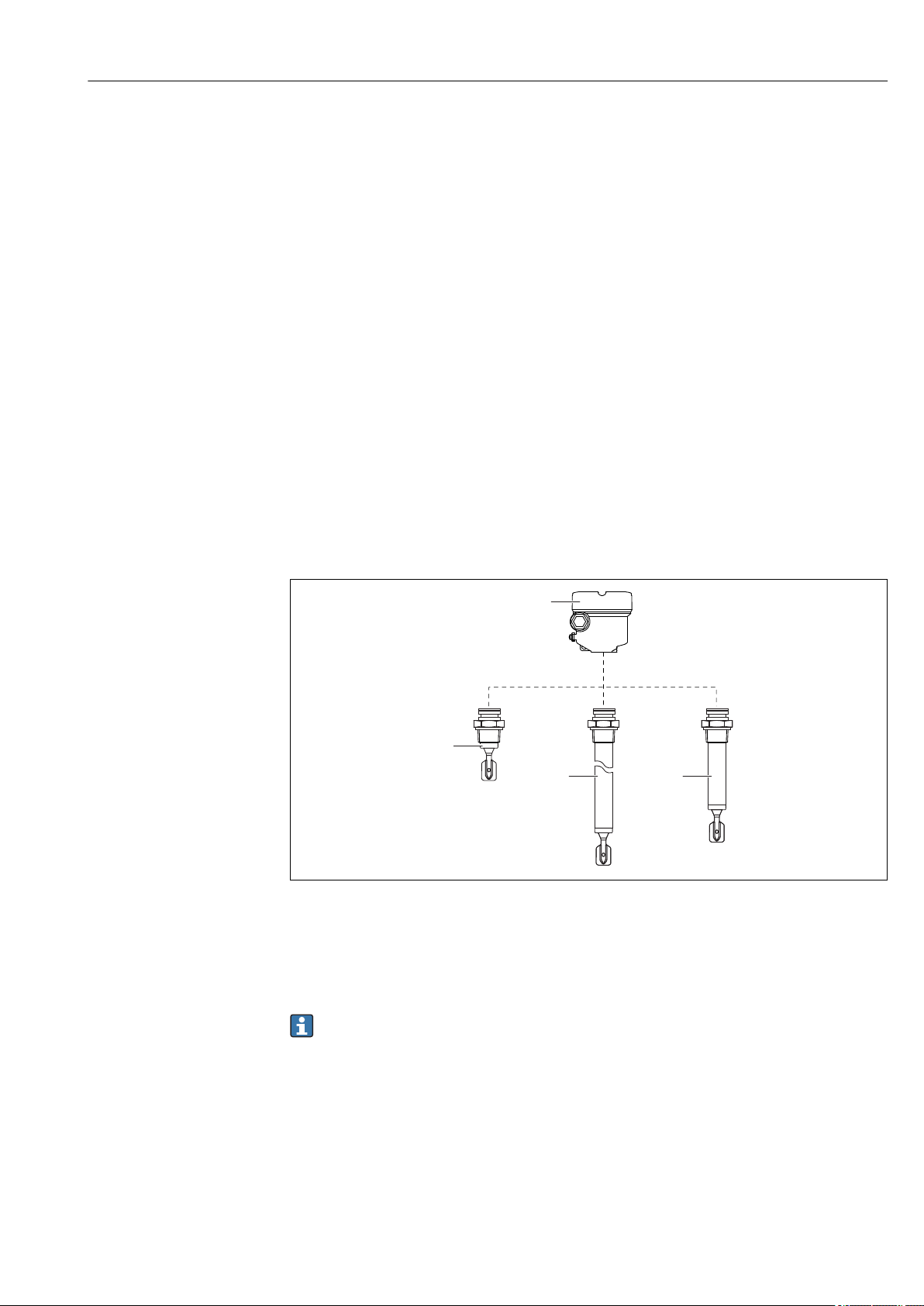
3.1 Product design
1 Product design
1 Housing with cover and electronic insert
2 Probe design compact
3 Probe design pipe extension
4 Probe design short pipe
A0031825
Identify the electronic insert via the order code on the nameplate .
Endress+Hauser 7
Page 8
Incoming acceptance and product identification Liquiphant FTL41
Order code: Ser. no.:
Ext. ord. cd.:
L:
FW:
Dev.Rev.:
Pmax:
0.83 W PNP
2
3
5
1
4
4
4 Incoming acceptance and product
identification
4.1 Incoming acceptance
Check the following during goods acceptance:
Are the order codes on the delivery note and the product sticker identical?
Are the goods undamaged?
Do the nameplate data match the ordering information on the delivery note?
If required (see nameplate): Are the Safety Instructions, e. g. XA, provided?
Is the device properly secured?
If one of these conditions is not met, please contact the manufacturer's sales office.
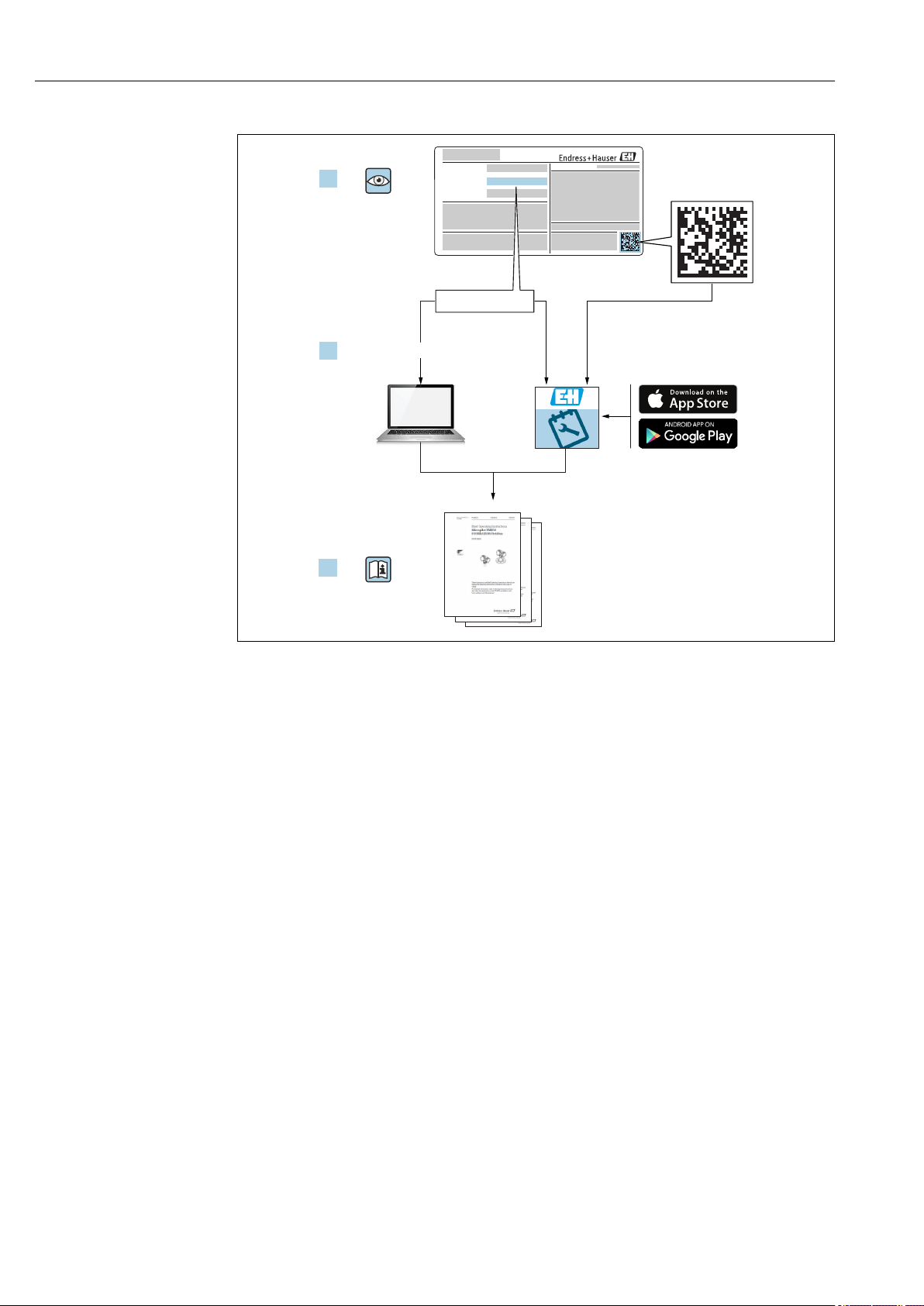
4.2 Product identification
The measuring device can be identified in the following ways:
• Nameplate data
• Extended order code with breakdown of the device features on the delivery note
• Enter serial number from nameplates in W@M Device Viewer
(www.endress.com/deviceviewer): All of the information on the measuring device is
displayed along with an overview of the scope of technical documentation provided
• Enter the serial number on the nameplate into the Endress+Hauser Operations App or
use the Endress+Hauser Operations App to scan the 2-D matrix code (QR Code) on the
nameplate
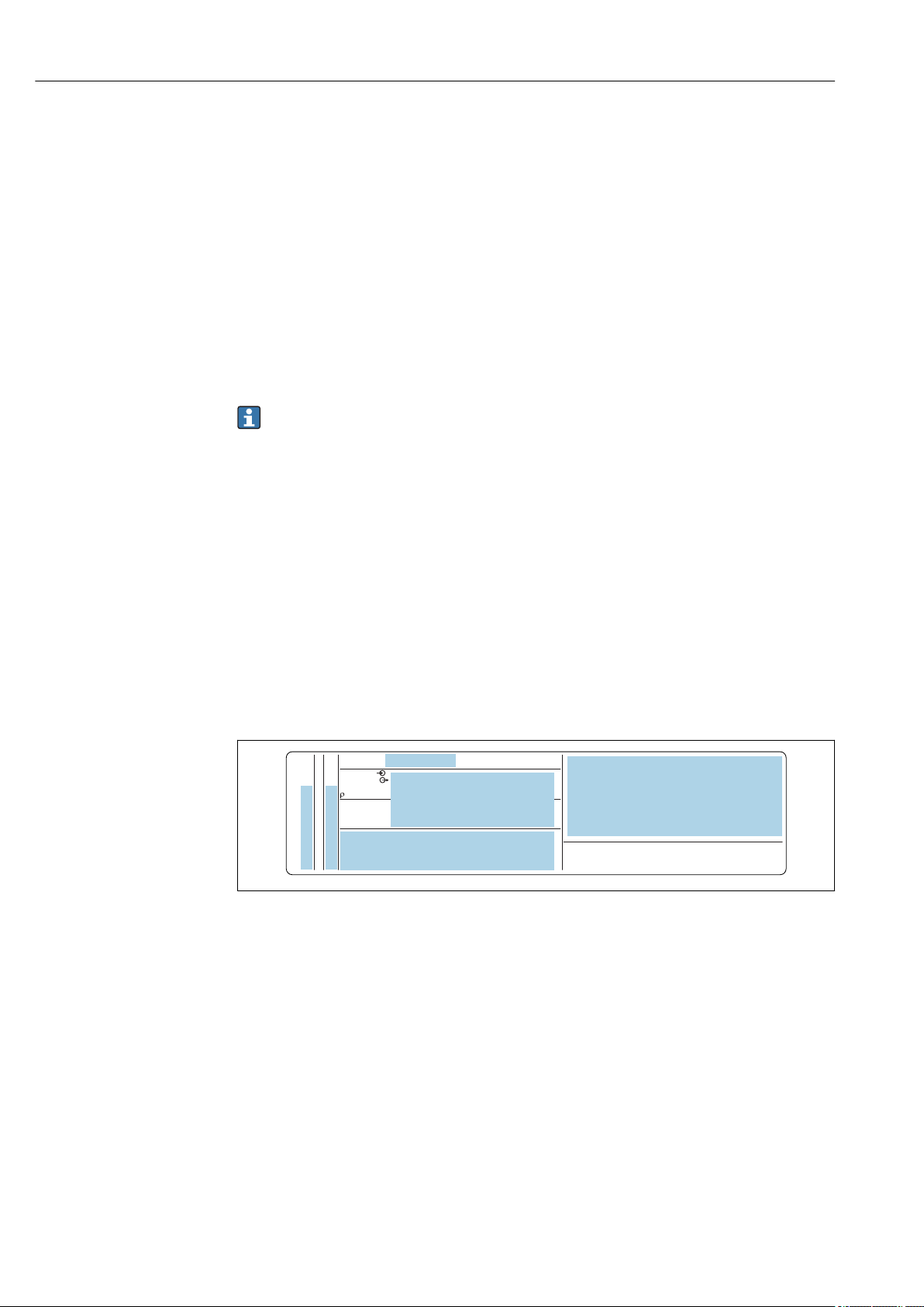
4.2.1 Nameplate
2 Nameplate specifications
1 Manufacturer name and device name
2 Manufacturer address
3 Order number, external order code, serial number
4 Technical data
5 Approval-specific information
4.2.2 Manufacturer address
Endress+Hauser SE+Co. KG
Hauptstraße 1
79689 Maulburg, Germany
Address of the manufacturing plant: See nameplate.
A0038187
8 Endress+Hauser
Page 9
Liquiphant FTL41 Mounting
4.3 Storage and transport
4.3.1 Storage conditions
Use original packaging.
Storage temperature
–40 to +80 °C (–40 to +176 °F)
optional: –52 °C (–62 °F), –60 °C (–76 °F)
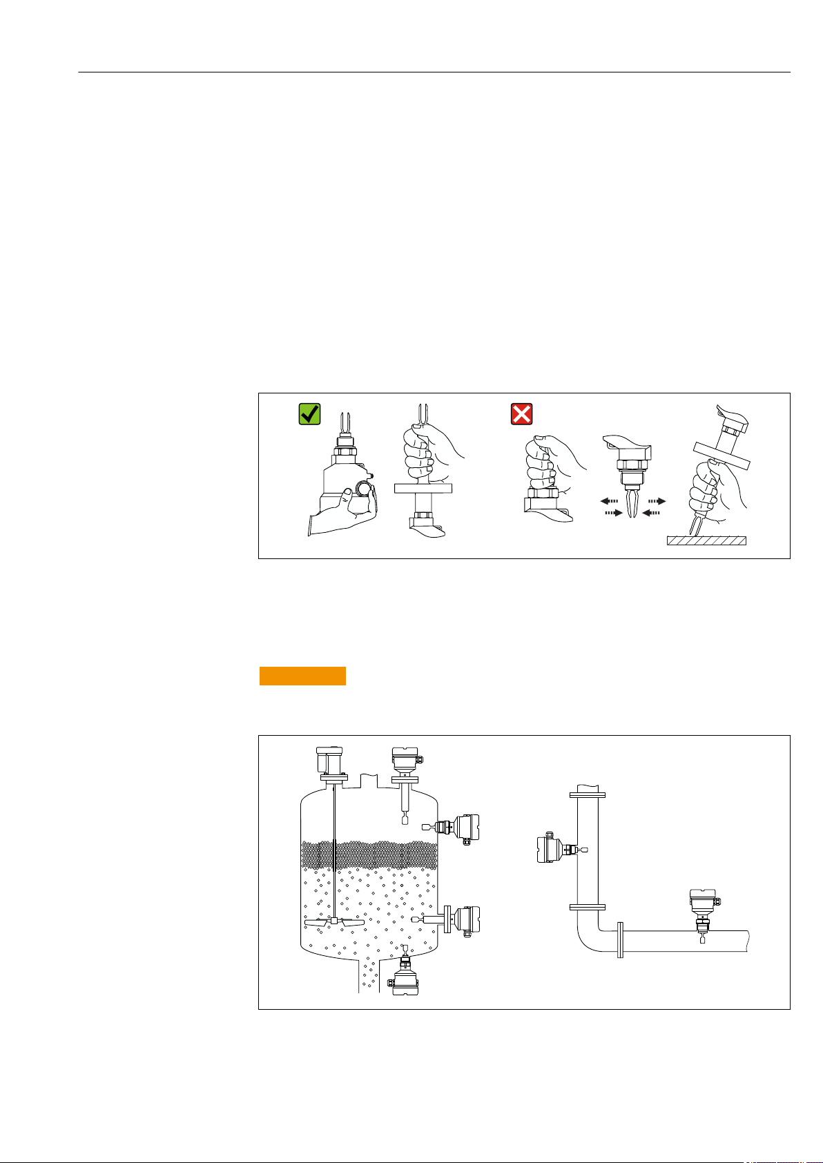
4.3.2 Transporting the device
• Transport the device to the measuring point in the original packaging
• Hold the device by the housing, temperature spacer, flange or extension pipe
• Do not bend, shorten or extend the tuning fork
3 Handling the device during transportation
5 Mounting
WARNING
L
Loss of protection rating if the device is opened in a wet environment.
Only open the device in a dry environment!
‣
A0034846
A0036954
4 Installation in any position in container, pipe or tank
Endress+Hauser 9
Page 10
Mounting Liquiphant FTL41
~13 (0.5)
~4 (0.16)
~12.5 (0.49)
D
A B C
D
D
> 25 (0.98)
D
5.1 Mounting conditions
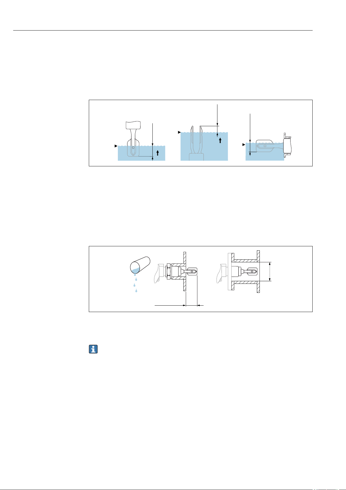
5.1.1 Taking the switch point into consideration
Typical switch points, depending on the orientation of the point level switch
(water +23 °C (+73 °F))
A0037915
5 Typical switch points. Unit of measurement mm (in)
A Installation from above
B Installation from below
C Installation from the side
D Switch point
5.1.2 Take viscosity into consideration
Low viscosity
6 Installation example for low-viscosity liquids. Unit of measurement mm (in)
D Diameter of installation socket: at least 50 mm (2.0 in)
Low viscosity, e. g. water: < 2 000 mPa⋅s
It is permitted to position the tuning fork within the installation socket.
A0033297
10 Endress+Hauser
Page 11
Liquiphant FTL41 Mounting
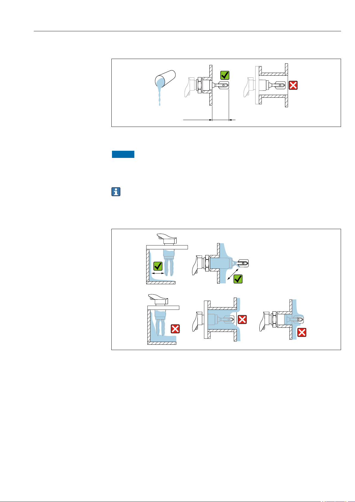
> 40 (1.57)
High viscosity
A0037348
7 Installation example for a highly viscous liquid. Unit of measurement mm (in)
NOTICE
Highly viscous liquids may cause switching delays.
Make sure that the liquid can run off the tuning fork easily.
‣
Deburr the socket surface.
‣
High viscosity, e. g. viscous oils: < 10 000 mPa⋅s
The tuning fork must be located outside the installation socket!
5.1.3 Avoiding buildup
A0033239
8 Installation examples for a highly viscous process medium
• Use short installation sockets to ensure that the turning fork can project freely into the
vessel.
• Install preferably flush-mounted on vessels or in pipes.
• Leave sufficient distance between the buildup expected on the tank wall and the tuning
fork.
Endress+Hauser 11
Page 12

Mounting Liquiphant FTL41
5.1.4 Take clearance into consideration
A0033236
9 Take clearance into consideration
Allow sufficient space outside the tank for mounting, connection and settings involving
the electronic insert.
5.1.5 Support the device
A0031874
10 Support in the event of dynamic load
Support the device in the event of severe dynamic load. Maximum lateral loading capacity
of the pipe extensions and sensors: 75 Nm (55 lbf ft).
12 Endress+Hauser
Page 13

Liquiphant FTL41 Mounting
316L
316L/G1
5.1.6 Weld-in adapter with leakage hole
A0039230
11 Weld-in adapter with leakage hole
Weld in the welding neck in such a way that the leakage hole is pointing downwards. This
enables any leaks to be detected quickly.
5.2 Mounting the measuring device
5.2.1 Required tools
• Open-ended wrench for sensor installation
• Screwdriver for electrical connection
5.2.2 Installation
Horizontal installation in vessels
Align the tuning fork with the marking
A0039125
12 Marking to align the tuning fork
Use the marking to align the tuning fork in such a way that medium can run off easily and
deposit buildup is avoided.
The following can be used as the marking:
• Material specification, thread description or circle on the hexagonal nut or on the weldin adapter
• The II symbol on the back of the flange or Tri-Clamp
Endress+Hauser 13
Page 14

Mounting Liquiphant FTL41
1.
2.
3
0.7 Nm
3
3.
Installing in pipes
A0034851
13 Marking and fork position
• Flow velocity up to 5 m/s with viscosity 1 mm2/s (cSt) and density 1 g/cm3 (SGU)
Check for correct functioning in the event of other process medium conditions
• The marking on the adapter points in the flow direction; the flow is thus not severely
obstructed
• The marking can be identified while the device is installed
Screwing in the device
14 Screwing in the device
• Turn by the hex bolt only, 15 to 30 Nm (11 to 22 lbf ft)
• Do not turn at the housing!
Aligning the cable entry
15 Housing with external locking screw
The locking screw is not tightened when the device is delivered.
A0034852
A0037347
1. Release the external locking screw.
2. Turn the housing, align the cable entry.
3. Tighten the external locking screw.
14 Endress+Hauser
Page 15

Liquiphant FTL41 Electrical connection
5.3 Sliding sleeves
See the "Accessories" section.
5.4 Post-installation check
Is the measuring device undamaged (visual inspection)?
Does the measuring device conform to the measuring point specifications?
For example:
• Process temperature
• Process pressure
• Ambient temperature range
• Measuring range
Are the measuring point number and labeling correct (visual inspection)?
Is the measuring device adequately protected against precipitation and direct sunlight?
Is the device properly secured?
6 Electrical connection
6.1 Connection conditions
6.1.1 Connecting protective earth (PE)
The protective earth conductor at the device must only be connected if the device's
operating voltage is ≥ 35 VDC or ≥ 16 VACeff.
When the device is used in hazardous areas, it must always be included in the potential
equalization of the system, irrespective of the operating voltage.
The plastic housing is available with or without an external protective earth
connection (PE).
6.2 Connecting the measuring device
6.2.1 3-wire DC-PNP (electronic insert FEL42)
• Three-wire direct current version
• Switches the load via the transistor (PNP) and separate connection, e. g. in conjunction
with programmable logic controllers (PLC), DI modules as per EN 61131-2
Supply voltage
WARNING
L
Failure to use the prescribed power unit.
Risk of potentially life-threatening electric shock!
The FEL42 may only be powered by power supply units with secure galvanic isolation
‣
in accordance with IEC 61010-1.
U = 10 to 55 V
Observe the following in accordance with IEC/EN61010-1: Provide a suitable circuit
breaker for the device and limit the current to 500 mA, e. g. through the installation
of a 0.5 A fuse (slow-blow) in the power supply circuit.
Endress+Hauser 15
DC
Page 16

Electrical connection Liquiphant FTL41
0.5 A
L+ L-
1
3
MIN
MAX
>0,7
L-L+
U = 10...55 V DC
I max: 350 mA
>0,5
1
3
!
K
PE
1 2 3
B
4 3 1
2
1
34
M12
I 350 mA
max
U 55 V
max
K
I
L
A
L+L-
K
Power consumption
P < 0.5 W
Current consumption
I ≤ 10 mA (without load)
The red LED flashes in the event of an overload or short-circuit. Check for an overload or
short-circuit every five seconds.
Load current
I ≤ 350 mA
Residual current
I < 100 µA (for blocked transistor)
Residual voltage
U < 3 V (for switched through transistor)
Behavior output signal
• OK status: switched through
• Demand mode: blocked
• Alarm: blocked
Terminal assignment
16 Terminal assignment FEL42
A Terminal assignment at electronic insert
B Terminal assignment on connector M12
16 Endress+Hauser
A0036056
Page 17

Liquiphant FTL41 Electrical connection
MAX
RD YE GN
MIN
K
K
K
(L–)
(L–)
(L–)
I
L
<100 µA
I
L
3
3
3
1
1
1
L+
L+
L+
ΔU
ΔU
K
(L–)
<100 µA
3
1
L+
(L–)
<100 µA
3
1
L+
K
Behavior of the switch output and signaling
A0033508
17 FEL42 switching behavior, signaling LED
MAXDIP switch for setting the MAX safety
MIN DIP switch for setting the MIN safety
RD LED red for warning or alarm
YE LED yellow switch status
GN LED green operational status, device on
ILLoad current switched through
6.2.2 Universal current connection with relay output (electronic
insert FEL44)
• Switches the loads via 2 floating change-over contacts
• Two separate change-over contacts (DPDT)
WARNING
L
In the event of an error, the electronic insert can exceed the limit temperature for
touchable surfaces, posing the risk of burns.
Do not touch the electronics in the event of an error!
‣
Supply voltage
U= 19 to 253 VAC / 19 to 55 V
Observe the following in accordance with IEC/EN61010-1: Provide a suitable circuit
breaker for the device and limit the current to 500 mA, e. g. with the installation of a
0.5 A fuse (slow-blow) in the phase (not the neutral conductor) of the power supply
circuit.
Power consumption
Endress+Hauser 17
P < 25 VA,< 1.3 W
Connectable load
Loads switched via 2 floating change-over contacts (DPDT)
• IAC ≤ 6 A (Ex de 4 A), U~ ≤ AC 253 V; P~ ≤ 1 500 VA, cos φ = 1, P~ ≤ 750 VA,
cos φ > 0.7
• IDC ≤ 6 A (Ex de 4 A) to DC 30 V, IDC ≤ 0.2 A to 125 V
According to IEC 61010, the following applies: Total voltage from relay outputs and power
supply ≤ 300 V
DC
Page 18

Electrical connection Liquiphant FTL41
L1
MIN
>0,7
MAX
>0,5
N
4
3 5
876
U = 19...55 V DC
U 19...253 V AC
~
~
!
0.5 A
1
2 2
L1
L+
NO NONC NCC CNL-PE
1 2 3 64 75 8
Electronic insert FEL42 DC PNP preferred for small DC load currents, e. g. for connection to
a PLC.
Relay contact material: silver/nickel AgNi 90/10
When connecting a device with high inductivity, provide spark quenching to protect the
relay contact. A fine-wire fuse (depending on the connected load) protects the relay
contact in the event of a short-circuit.
Both relay contacts switch simultaneously.
Behavior output signal
• OK state: Relay energized
• Demand mode: Relay de-energized
• Alarm: Relay de-energized
Terminal assignment
A0036057
18 Universal current connection with relay output, electronic insert FEL44
1 When bridged, the relay output works with NPN logic
2 Connectable load
18 Endress+Hauser
Page 19

Liquiphant FTL41 Electrical connection
3 54
3 54
6 87
6 87
3 54
33554
4
6 87
66887
7
MAX
RD YE GN
MIN
Behavior of the switch output and signaling
A0033513
19 FEL44 switching behavior, signaling LED
MAXDIP switch for setting the MAX safety
MIN DIP switch for setting the MIN safety
RD LED red for alarm
YE LED yellow switch status
GN LED green operational status, device on
6.2.3 2-wire NAMUR > 2.2 mA/< 1.0 mA (electronic insert FEL48)
• For connection to the isolating switch repeater as per NAMUR (IEC 60947-5-6), e. g.
Nivotester FTL325N from Endress+Hauser
• Signal transmission H-L edge 2.2 to 3.8 mA/0.4 to 1.0 mA as per IEC 60947-5-6
(NAMUR) on two-wire cabling
Supply voltage
U = 8.2 V
Power consumption
P < 50 mW
Behavior output signal
• OK state: Current 2.2 to 3.8 mA
• Demand mode: Current 0.4 to 1.0 mA
• Alarm: Current 0.4 to 1.0 mA
DC
Observe the following in accordance with IEC/EN61010-1: Provide a suitable circuit
breaker for the device.
Endress+Hauser 19
Page 20

Electrical connection Liquiphant FTL41
"
– +
MIN
MAX
>0,7
IEC 60947-5-6
8,2 V DC NAMUR
>0,5
1
2
!
L-
I
H
L
L+
.
-
1 2
MAX
RD YE GN
MIN
1
1
1
1
1
2
2
2
2
2
L+
L+
L+
L+
L+
2.2...3.8 mA
0.4...1.0 mA
2.2...3.8 mA
0.4...1.0 mA
< 1.0 mA
L-
L-
L-
L-
L-
Terminal assignment
20 2-wire NAMUR > 2.2 mA/< 1.0 mA, electronic insert FEL48
Behavior of the switch output and signaling
21 FEL48 switching behavior and signaling
MAXDIP switch for setting the MAX safety
MIN DIP switch for setting the MIN safety
RD LED red for alarm
YE LED yellow switch status
GN LED green operational status, device on
6.2.4 Cable entry
A0036058
A0037694
Required tools
• Flat-blade screwdriver (0.6 x 3.5 mm) for terminals
• Torque spanner (8 Nm) for M20 cable gland
20 Endress+Hauser
Page 21

Liquiphant FTL41 Operation options
1
2
3
!
ød
3.5
A0018023
22 Cable entry, electronic insert
1 M20 cable gland
2
Conductor cross-section, 2.5 mm2 maximum (AWG14)
3
Conductor cross-section, 4.0 mm2 maximum (AWG12)
ød Nickel-plated brass 7 to 10.5 mm (0.28 to 0.41 in)
ød Plastic 5 to 10 mm (0.2 to 0.38 in)
ød Stainless steel 7 to 12 mm (0.28 to 0.47 in)
Secure the cable gland and tighten the union nut of the cable gland, 8 Nm (5.9 lbf ft)
torque. Screw the enclosed cable glands into the housing with a torque of
3.75 Nm (2.76 lbf ft).
6.3 Post-connection check
Is the device or cable undamaged (visual inspection)?
Do the cables used comply with the requirements?
Do the mounted cables have adequate strain relief?
Are the cable glands mounted and firmly tightened?
Does the supply voltage match the specifications on the nameplate?
No reverse polarity, is terminal assignment correct?
If supply voltage is present, is the green LED lit?
Are all the housing covers installed and tightened?
Optional: Is the cover with securing screw tightened?
7 Operation options
7.1 Overview of operation options
7.1.1 Operation concept
Operation with DIP switches on the electronic insert
Endress+Hauser 21
Page 22

Commissioning Liquiphant FTL41
L1
MIN
>0,7
MAX
>0,5
N
4
3 5 876
U = 19...55 V DC
U 19...253 V AC
~
~
1 2 3 64 75 8
1
2
3
4
5
6
7
7.1.2 Elements on the electronic insert
A0039317
23 Example electronic insert FEL44
1 LED red, for warning or alarm
2 LED yellow, switch status
3 LED green, operational status (LED green lights up = device on)
4 DIP switch to set the density to 0.7 or 0.5
5 Relay contact terminals
6 Power supply terminals
7 DIP switch for setting MAX/MIN safety
8 Commissioning
8.1 Function check
Before commissioning the measuring point, check whether the post-installation and postconnection checks have been performed:
• "Post-installation check" checklist → 15
• "Post-connection check" checklist → 21
8.2 Powering up the measuring device
During the power-up time, the device output is in the safety-oriented state, or in the alarm
state if available.
The output will be in the correct state max. three seconds after powering up the device.
9 Diagnostics and troubleshooting
The device indicates warnings and errors via the LEDs on the electronic insert. All the
device warnings and faults are for information purposes only and do not have a safety
function. Depending on the diagnostic message, the device behaves as per a warning or
fault condition.
The device behaves in accordance with NAMUR Recommendation NE131 "NAMUR
standard device requirements for field devices for standard applications".
9.1 LED at electronic insert
LED green not lit
Possible cause: No power supply
Troubleshooting: Check plug, cable and power supply
22 Endress+Hauser
Page 23

Liquiphant FTL41 Maintenance
LED flashes red
Possible cause: Overload or short-circuit in load circuit
Troubleshooting: Clear the short-circuit
Reduce maximum load current to below 350 mA
LED red continuously lit
Possible cause: Internal sensor error or electronic fault
Troubleshooting: Replace device
10 Maintenance
No special maintenance work is required.
10.1 Maintenance tasks
10.1.1 Cleaning
It is not permitted to use the device with abrasive media. Material abrasion on the tuning
fork can result in the device malfunctioning.
• Clean the tuning fork as necessary
• Cleaning is also possible in the installed state, e. g. CIP Cleaning in Place and SIP
Sterilization in Place
Endress+Hauser 23
Page 24

Repair Liquiphant FTL41
11 Repair
11.1 General information
11.1.1 Repair concept
Endress+Hauser repair concept
• Measuring devices have a modular design
• Customers can carry out repairs
For more information on service and spare parts, please contact your Endress+Hauser
sales representative.
11.1.2 Repair of Ex-certified devices
WARNING
L
Limitation of electrical safety due to incorrect connection!
Risk of explosion!
Only specialist personnel or the Endress+Hauser service team may carry out repairs on
‣
Ex-certified devices.
Relevant standards and national regulations on hazardous areas, safety instructions
‣
and certificates must be observed.
Use only original Endress+Hauser spare parts.
‣
Please note the device designation on the nameplate. Only identical parts may be used
‣
as replacements.
Carry out repairs according to the instructions. On completion of repair work, carry out
‣
the routine test specified for the device.
Only the Endress+Hauser service team is permitted to modify a certified device and
‣
convert it to another certified version.
All repairs and modifications must be documented.
‣
11.2 Spare parts
• Some replaceable measuring device components are identified by means of a spare part
nameplate. This contains information about the spare part.
• All the spare parts for the measuring device along with the order code are listed in the
W@M Device Viewer (www.endress.com/deviceviewer) and can be ordered. If available,
users can also download the associated Installation Instructions.
Measuring device serial number or QR code:
Located on the device and spare part nameplate.
11.3 Return
The measuring device must be returned if the wrong device has been ordered or delivered.
As an ISO-certified company and also due to legal regulations, Endress+Hauser is obliged
to follow certain procedures when handling any returned products that have been in
contact with medium. To ensure safe, swift and professional device returns, please refer to
the procedure and conditions for returning devices provided on the Endress+Hauser
website at http://www.endress.com/support/return-material
24 Endress+Hauser
Page 25

Liquiphant FTL41 Accessories
140 (5.51) 32 (1.26)
115 (4.53)
122 (4.8)
11.4 Disposal
If required by the Directive 2012/19/EU on waste electrical and electronic equipment
(WEEE), our products are marked with the depicted symbol in order to minimize the
disposal of WEEE as unsorted municipal waste. Such products may not be disposed of as
unsorted municipal waste and can be returned to Endress+Hauser for disposal at
conditions stipulated in our General Terms and Conditions or as individually agreed.
12 Accessories
12.1 Device-specific accessories
12.1.1 Weather protection cover for single-compartment housing, metal
• Material: plastic
• Order number: 71438291
24 Weather protection cover for single-compartment housing, metal. Unit of measurement mm (in)
12.1.2 Plug-in jack
The plug-in jacks listed are suitable for use in the temperature range
–25 to +70 °C (–13 to +158 °F).
Plug-in jack M12 IP69
• Terminated at one end
• Elbowed 90°
• 5 m (16 ft) PVC cable (orange)
• Slotted nut 316L (1.4435)
• Body: PVC (orange)
• Order number: 52024216
A0038280
Endress+Hauser 25
Page 26

Accessories Liquiphant FTL41
27.5
(1.08)
40³
(1.57)
27.5
(1.08)
40³
(1.57)
22 (0.87)
18 (0.71)
G 1 A
(1 NPT)
G 1½ A
(1½ NPT)
M6 (3x)
1
M6 (3x)
19 (0.75)
19 (0.75)
55
55
A0023713
25 Plug-in jack M12 IP69. Unit of measurement mm (in)
Plug-in jack M12 IP67
• Elbowed 90°
• 5 m (16 ft)PVC cable (gray)
• Slotted nut Cu Sn/Ni
• Body: PUR (blue)
• Order number: 52010285
26 Plug-in jack M12 IP67. Unit of measurement mm (in)
12.2 Sliding sleeves for unpressurized operation
Switch point, infinitely adjustable.
27 Sliding sleeves for unpressurized operation. Unit of measurement mm (in)
1 pe = 0 bar (0 psi)
A0022292
A0037666
G 1, DIN ISO 228/I
• Material: 1.4435 (AISI 316L)
26 Endress+Hauser
• Weight: 0.21 kg (0.46 lb)
• Order number: 52003978
• Order number: 52011888, approval: with inspection certificate EN 10204 - 3.1 material
Page 27

Liquiphant FTL41 Accessories
G 1 A
(1 NPT)
G 1½A
(1½ NPT)
ø60 (2.36)
~72 (2.83)
~70 76(2. )
2 (0.08)
2 (0.08)
ø60 (2.36)
18 71(0. )
5050
NPT 1, ASME B 1.20.1
• Material: 1.4435 (AISI 316L)
• Weight: 0.21 kg (0.46 lb)
• Order number: 52003979
• Order number: 52011889, approval: with inspection certificate EN 10204 - 3.1 material
G 1½, DIN ISO 228/I
• Material: 1.4435 (AISI 316L)
• Weight: 0.54 kg (1.19 lb)
• Order number: 52003980
• Order number: 52011890, approval: with inspection certificate EN 10204 - 3.1 material
NPT 1½, ASME B 1.20.1
• Material: 1.4435 (AISI 316L)
• Weight: 0.54 kg (1.19 lb)
• Order number: 52003981
• Order number: 52011891, approval: with inspection certificate EN 10204 - 3.1 material
12.3 High pressure sliding sleeves
• Switch point, infinitely adjustable
• For use in hazardous areas,
• Seal package made of graphite
• For G 1, G 1½: seal included in delivery
28 High pressure sliding sleeves. Unit of measurement mm (in)
G 1, DIN ISO 228/I
• Material: 1.4435 (AISI 316L)
• Weight: 1.13 kg (2.49 lb)
• Order number: 52003663
• Order number: 52011880, approval: with inspection certificate EN 10204 - 3.1 material
G 1, DIN ISO 228/I
• Material: AlloyC22
• Weight: 1.13 kg (2.49 lb)
• Approval: with inspection certificate EN 10204 - 3.1 material
• Order number: 71118691
NPT 1, ASME B 1.20.1
• Material: 1.4435 (AISI 316L)
• Weight: 1.13 kg (2.49 lb)
• Order number: 52003667
Endress+Hauser 27
• Order number: 52011881, approval: with inspection certificate EN 10204 - 3.1 material
A0037667
Page 28

Technical data Liquiphant FTL41
NPT 1, ASME B 1.20.1
• Material: AlloyC22
• Weight: 1.13 kg (2.49 lb)
• Approval: with inspection certificate EN 10204 - 3.1 material
• Order number: 71118694
G 1½, DIN ISO 228/1
• Material: 1.4435 (AISI 316L)
• Weight: 1.32 kg (2.91 lb)
• Order number: 52003665
• Order number: 52011882, approval: with inspection certificate EN 10204 - 3.1 material
G 1½, DIN ISO 228/1
• Material: AlloyC22
• Weight: 1.32 kg (2.91 lb)
• Approval: with inspection certificate EN 10204 - 3.1 material
NPT 1½, ASME B 1.20.1
• Material: 1.4435 (AISI 316L)
• Weight: 1.32 kg (2.91 lb)
• Order number: 52003669
• Order number: 52011883, approval: with inspection certificate EN 10204 - 3.1 material
NPT 1½, ASME B 1.20.1
• Material: AlloyC22
• Weight: 1.32 kg (2.91 lb)
• Approval: with inspection certificate EN 10204 - 3.1 material
• Order number: 71118695
13 Technical data
13.1 Input
13.1.1 Measured variable
Level (point level), MAX or MIN safety
13.1.2 Measuring range
Depends on the installation location and the pipe extension ordered
Maximum sensor length 6 m (20 ft)
13.2 Output
13.2.1 Output and input variants
Electronic inserts
3-wire DC-PNP (FEL42)
• Three-wire direct current version
• Switches the load via the transistor (PNP) and separate connection, e. g. in conjunction
with programmable logic controllers (PLC)
Universal current connection, relay output (FEL44)
Switches the loads via 2 floating change-over contacts
28 Endress+Hauser
Page 29

Liquiphant FTL41 Technical data
2-wire NAMUR > 2.2 mA/< 1.0 mA (FEL48)
• For separate switching unit
• Signal transmission H-L edge 2.2 to 3.8/0.4 to 1.0 mA as per EN 60947-5-6 (NAMUR)
on two-wire cabling
13.2.2 Output signal
Switch output
Preset switching times for the limit switches can be ordered for the following areas:
• 0.5 seconds when the tuning fork is covered and 1 second when it is uncovered (factory
setting)
• 0.25 seconds when the tuning fork is covered and 0.25 seconds when it is uncovered
(fastest setting)
• 1.5 seconds when the tuning fork is covered and 1.5 seconds when it is uncovered
• 5 seconds when the tuning fork is covered and 5 seconds when it is uncovered
13.2.3 Ex connection data
See safety instructions (XA): All data relating to explosion protection are provided in
separate Ex documentation and are available from the Downloads Area of the
Endress+Hauser-website. The Ex documentation is supplied as standard with all Ex
devices.
Endress+Hauser 29
Page 30

Technical data Liquiphant FTL41
T
a
T
p
+150
+302
+120
+248
+90
+194
+60
+140
+30
+86
0
32
-30
-22
-60
-76
70158
60140
50122
40104
3086
20
68
1050
032
[°C]
[°C]
[°F]
[°F]
13.3 Environment
13.3.1 Ambient temperature range
–40 to +70 °C (–40 to +158 °F)
In the hazardous area, the permitted ambient temperature can be limited depending on
the zones and gas groups. Pay attention to the information in the Ex documentation (XA).
The minimum permitted ambient temperature of the plastic housing is limited to
–20 °C (–4 °F); for North America, "indoor use" applies.
A0038718
29 For process temperature and FEL44 Tp > 90° max. load current 4 A
For outdoor operation in strong sunlight:
• Mount the device in the shade
• Avoid direct sunlight, particularly in warmer climatic regions
• Use a protective cover, which can be ordered as an accessory
13.3.2 Storage temperature
–40 to +80 °C (–40 to +176 °F)
optional: –52 °C (–62 °F), –60 °C (–76 °F)
13.3.3 Humidity
Operate up to 100 %. Do not open in a condensing atmosphere.
13.3.4 Operating altitude
As per IEC 61010-1 Ed.3:
• Up to 2 000 m (6 600 ft) above sea level
• Can be extended to 3 000 m (9 800 ft) above sea level if overvoltage protection is used
30 Endress+Hauser
13.3.5 Climate class
As per IEC 60068-2-38 test Z/AD
Page 31

Liquiphant FTL41 Technical data
13.3.6 Degree of protection
For housing with electrical connection
Coupling M20, plastic
• Single-chamber plastic: IP66/67 NEMA Type 4X
• Single-chamber aluminum: IP66/68 NEMA Type 4X/6P
Coupling M20, nickel-plated brass
Single-chamber aluminum: IP66/68 NEMA Type 4X/6P
Coupling M20, 316L
Single-chamber aluminum: IP66/68 NEMA Type 4X/6P
Thread M20
• Single-chamber plastic: IP66/67 NEMA Type 4X
• Single-chamber aluminum: IP66/68 NEMA Type 4X/6P
Thread G ½
• Single-chamber plastic: IP66/67 NEMA Type 4X
• Single-chamber aluminum: IP66/68 NEMA Type 4X/6P
Thread NPT ½
Single-chamber plastic: IP66/67 NEMA Type 4X
Thread NPT ¾
Single-chamber aluminum: IP66/68 NEMA Type 4X/6P
M12 plug
• Single-chamber plastic: IP66/67 NEMA Type 4X
• Single-chamber aluminum: IP66/67 NEMA Type 4X
13.3.7 Vibration resistance
As per IEC60068-2-64-2009
a(RMS) = 50 m/s², f = 5 to 2 000 Hz , t = 3 axes x 2 h
13.3.8 Shock resistance
As per IEC60068-2-27-2008: 300 m/s² [=30 gn] + 18ms
13.3.9 Mechanical load
Lateral loading capacity
Special mounting instructions
13.3.10 Electromagnetic compatibility
• Electromagnetic compatibility as per EN 61326 series and NAMUR recommendation
EMC (NE21).
• The requirements of EN 61326-3-1 are fulfilled.
13.4 Process
13.4.1 Process temperature range
Pay attention to the pressure and temperature dependence (see the "Sensor process
pressure range" section )
–40 to +150 °C (–40 to +302 °F)
Endress+Hauser 31
Page 32

Technical data Liquiphant FTL41
p
e
T
p
+150
+302
0
32
-40
-40
40580
032
[bar]
[°C]
[psi]
[°F]
13.4.2 Thermal shock
≤ 120 K/s
13.4.3 Process pressure range
A0038719
30 Process temperature FTL41
WARNING
L
The maximum pressure for the measuring device is dependent on the lowest-rated
element, with regard to pressure, of the selected components. This means that it is
necessary to pay attention to the process connection as well as the sensor.
For pressure specifications, see the "Mechanical construction" section.
‣
The measuring device must be operated only within the specified limits!
‣
The Pressure Equipment Directive (2014/68/EU) uses the abbreviation "PS". The
‣
abbreviation "PS" corresponds to the MWP (maximum working pressure) of the
measuring device.
Approved pressure values of the flanges at higher temperatures, taken from the following
standards:
• pR EN 1092-1: 2005 With regard to its stability-temperature property, the material
1.4435 is identical to 1.4404, which is classed as 13E0 in EN 1092-1 Tab. 18. The
chemical composition of the two materials can be identical.
• ASME B 16.5
• JIS B 2220
In each case, the lowest value from the derating curves of the device and the selected
flange applies.
Process pressure range of the sensors
PN: 40 bar (580 psi)
13.4.4 Test pressure
32 Endress+Hauser
Overpressure
PN = 40 bar (580 psi): Test pressure = 1.5 · PN max. 60 bar (870 psi) dependent on the
process connection selected
The device function is limited during the pressure test.
The mechanical integrity is guaranteed at pressures up to 1.5 times the process nominal
pressure PN.
Page 33

Liquiphant FTL41 Technical data
13.4.5 Density
• Switch position > 0.7 g/cm3 = order configuration
Standard setting for liquids with a density > 0.7 g/cm
3
• Switch position > 0.5 g/cm3 = can be set via DIP switch
For liquids with a density > 0.5 g/cm3 to < 0.8 g/cm
• Order option: 0.4 g/cm
3
For liquids with a density > 0.4 g/cm3 to < 0.6 g/cm
3
3
If this option has been selected, the density setting is then always set to 0.4 g/cm3. The
setting can no longer be changed.
13.4.6 Pressure tightness
Up to vacuum
In vacuum evaporation systems, the density of the liquids can drop to a very low value:
select density setting 0.4.
13.5 Additional technical data
Latest technical information: Endress+Hauser website: www.endress.com →
Downloads.
Endress+Hauser 33
Page 34

Page 35

Page 36

*71440977*
71440977
www.addresses.endress.com
 Loading...