

Page 1
TI01402F/00/EN/02.19
71440553
2019-06-29
Products Solutions Services
Technical Information
Liquiphant FTL41
Vibronic
Limit switch for liquids
Application
• Limit switch for minimum or maximum detection in tanks, containers and piping
with all types of liquids, even in hazardous areas
• Process temperature range: –40 to +150 °C (–40 to +302 °F)
• Pressures up to 40 bar (580 psi)
• Viscosities up to 10 000 mPa⋅s
• Ideal substitute for float switches, as reliable function is not affected by flow,
turbulence, air bubbles, foam, vibration, solids content or buildup.
Advantages
• No calibration needed: Quick, low-cost commissioning
• Design in accordance with ASME B31.3 and CRN approval
• No mechanically moving parts: No maintenance, no wear, long operating life
• Functional safety: Monitoring of vibration frequency of the tuning fork
• RFID TAG – easy measuring point identification and simplified data access
Page 2

Table of contents
Liquiphant FTL41
About this document ........................ 4
Symbols ................................... 4
Function and system design ................... 5
point level detection ........................... 5
Measuring principle ........................... 5
Measuring system ............................ 5
Input ..................................... 5
Measured variable ............................ 5
Measuring range ............................. 5
Output ................................... 5
Output and input variants ........................ 5
Output signal ................................ 6
Ex connection data ............................ 6
3-wire DC-PNP (electronic insert FEL42) ......... 6
Supply voltage ............................... 6
Power consumption ............................ 6
Current consumption ........................... 6
Load current ................................. 6
Residual current .............................. 6
Residual voltage .............................. 6
Behavior output signal .......................... 6
Terminal assignment ........................... 7
Behavior of the switch output and signaling ............ 7
Mounting ................................ 12
Mounting location, orientation ................... 12
Installation instructions ........................ 12
Taking marking into account ..................... 14
Weld-in adapter with leakage hole ................ 15
Sliding sleeves .............................. 15
Aligning the cable entry ........................ 15
Special mounting instructions .................... 15
Environment .............................. 16
Ambient temperature range ..................... 16
Storage temperature .......................... 16
Humidity .................................. 16
Operating altitude ............................ 16
Climate class ............................... 16
Degree of protection .......................... 16
Vibration resistance .......................... 17
Shock resistance ............................. 17
Mechanical load ............................. 17
Electromagnetic compatibility .................... 17
Process .................................. 17
Process temperature range ...................... 17
Thermal shock .............................. 17
Process pressure range ........................ 17
Test pressure ............................... 18
Density ................................... 18
Pressure tightness ........................... 18
Universal current connection with relay output
(electronic insert FEL44) ..................... 7
Supply voltage ............................... 8
Power consumption ............................ 8
Connectable load .............................. 8
Behavior output signal .......................... 8
Terminal assignment ........................... 8
Behavior of the switch output and signaling ............ 9
2-wire NAMUR > 2.2 mA/< 1.0 mA (electronic
insert FEL48) .............................. 9
Supply voltage ............................... 9
Power consumption ............................ 9
Behavior output signal .......................... 9
Terminal assignment .......................... 10
Behavior of the switch output and signaling ........... 10
Performance characteristics .................. 10
Reference operating conditions ................... 10
Maximum measured error ...................... 11
Hysteresis ................................. 11
Non-repeatability ............................ 11
Influence of the process temperature ............... 11
Influence of the process pressure .................. 11
Influence of the density of the process medium (at room
temperature and normal pressure) ................. 11
Mechanical construction .................... 18
Design, dimensions ........................... 18
Dimensions ................................ 19
Weight ................................... 25
Materials ................................. 25
Surface roughness ........................... 25
Operability ............................... 25
Operation concept ............................ 25
Elements on the electronic insert .................. 26
Terminals ................................. 26
Local operation ............................. 26
Certificates and approvals ................... 27
CE mark .................................. 27
RCM-Tick marking ............................ 27
Ex approval ................................ 27
Overfill protection ............................ 27
Marine approvals ............................ 27
CRN approval ............................... 27
Test reports ................................ 27
Pressure Equipment Directive .................... 28
Process seal as per ANSI/ISA 12.27.01 .............. 28
China RoHS symbol ........................... 28
RoHS ..................................... 28
Additional certification ......................... 28
ASME B 31.3 ............................... 28
2 Endress+Hauser
Page 3

Liquiphant FTL41
Ordering information ....................... 29
TAG ..................................... 29
Accessories ............................... 29
Device-specific accessories ...................... 29
Sliding sleeves for unpressurized operation ........... 30
High pressure sliding sleeves ..................... 31
Supplementary documentation ............... 33
Special documentation ......................... 33
Device-dependent supplementary documentation ....... 33
Endress+Hauser 3
Page 4
About this document
DANGER
WARNING
CAUTION
NOTICE
A
1.
-
.
Symbols Safety symbols
This symbol alerts you to a dangerous situation. Failure to avoid this situation will result in serious or
fatal injury.
This symbol alerts you to a dangerous situation. Failure to avoid this situation can result in serious or
fatal injury.
This symbol alerts you to a dangerous situation. Failure to avoid this situation can result in minor or
medium injury.
This symbol contains information on procedures and other facts which do not result in personal
injury.
Electrical symbols
Ground connection
Grounded clamp, which is grounded via a grounding system.
Protective earth (PE)
Ground terminals, which must be grounded prior to establishing any other connections. The ground
terminals are located on the inside and outside of the device.
Liquiphant FTL41
Symbols for certain types of information
Permitted
Procedures, processes or actions that are permitted.
Forbidden
Procedures, processes or actions that are forbidden.
Tip
Indicates additional information
Reference to documentation
Reference to another section
, 2., 3. Series of steps
Symbols in graphics
A, B, C ... View
1, 2, 3 ... Item numbers
Hazardous area
Safe area (non-hazardous area)
4 Endress+Hauser
Page 5
Liquiphant FTL41
A B
Function and system design
point level detection
Measuring principle
Measuring system
Maximum or minimum detection for liquids in tanks or pipes in all industries. Suitable for leakage
monitoring, dry-running protection, pump protection or overfill protection, for example .
Specific versions are suitable for use in hazardous areas.
The point level switch differentiates between the "covered" and "not covered" conditions.
Depending on the MIN (minimum detection) or MAX (maximum detection) modes, there are two
possibilities in each case: OK status and demand mode
OK status
• In MIN mode, the fork is covered, e. g. pump protection
• In MAX mode, the fork is not covered e. g. overfill protection
Demand mode
• In MIN mode, the fork is not covered e. g. pump protection
• In MAX mode, the fork is covered e. g. overfill protection
The sensor's tuning fork vibrates at its intrinsic frequency. As soon as the liquid covers the tuning
fork, the vibration resistance decreases. The change in frequency causes the point level switch to
switch.
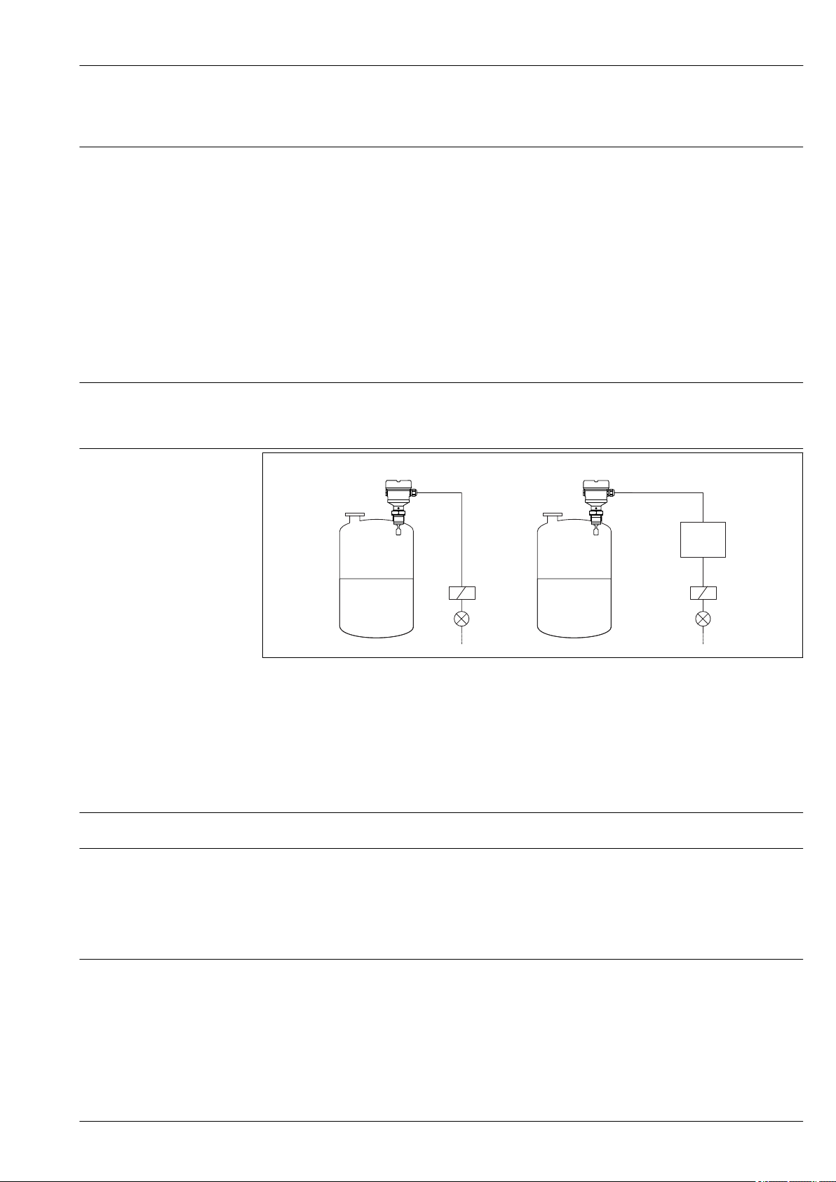
1 Example of a measuring system
A Device for direct connection of a load
B Device for connection to a separate switching unit or PLC
Input
Measured variable
Measuring range
Level (point level), MAX or MIN safety
Depends on the installation location and the pipe extension ordered
Output
Output and input variants Electronic inserts
3-wire DC-PNP (FEL42)
• Three-wire direct current version
• Switches the load via the transistor (PNP) and separate connection, e. g. in conjunction with
programmable logic controllers (PLC)
Universal current connection, relay output (FEL44)
Switches the loads via 2 floating change-over contacts
A0035308
Endress+Hauser 5
Page 6

2-wire NAMUR > 2.2 mA/< 1.0 mA (FEL48)
• For separate switching unit
• Signal transmission H-L edge 2.2 to 3.8/0.4 to 1.0 mA as per EN 60947-5-6 (NAMUR) on twowire cabling
Output signal Switch output
Preset switching times for the limit switches can be ordered for the following areas:
• 0.5 seconds when the tuning fork is covered and 1 second when it is uncovered (factory setting)
• 0.25 seconds when the tuning fork is covered and 0.25 seconds when it is uncovered (fastest
setting)
• 1.5 seconds when the tuning fork is covered and 1.5 seconds when it is uncovered
• 5 seconds when the tuning fork is covered and 5 seconds when it is uncovered
Liquiphant FTL41
Ex connection data
Supply voltage
Power consumption
See safety instructions (XA): All data relating to explosion protection are provided in separate Ex
documentation and are available from the Downloads Area of the Endress+Hauser-website. The Ex
documentation is supplied as standard with all Ex devices.
3-wire DC-PNP (electronic insert FEL42)
• Three-wire direct current version
• Switches the load via the transistor (PNP) and separate connection, e. g. in conjunction with
programmable logic controllers (PLC), DI modules as per EN 61131-2
WARNING
L
Failure to use the prescribed power unit.
Risk of potentially life-threatening electric shock!
The FEL42 may only be powered by power supply units with secure galvanic isolation in
‣
accordance with IEC 61010-1.
U = 10 to 55 V
Observe the following in accordance with IEC/EN61010-1: Provide a suitable circuit breaker for
the device and limit the current to 500 mA, e. g. through the installation of a 0.5 A fuse (slowblow) in the power supply circuit.
P < 0.5 W
DC
Current consumption
Load current
Residual current
Residual voltage
Behavior output signal
I ≤ 10 mA (without load)
The red LED flashes in the event of an overload or short-circuit. Check for an overload or shortcircuit every five seconds.
I ≤ 350 mA
I < 100 µA (for blocked transistor)
U < 3 V (for switched through transistor)
• OK status: switched through
• Demand mode: blocked
• Alarm: blocked
6 Endress+Hauser
Page 7
Liquiphant FTL41
0.5 A
L+ L-
1
3
MIN
MAX
>0,7
L-L+
U = 10...55 V DC
I max: 350 mA
>0,5
1
3
!
K
PE
1 2 3
B
4 3 1
2
1
34
M12
I 350 mA
max
U 55 V
max
K
I
L
A
L+L-
K
MAX
RD YE GN
MIN
K
K
K
(L–)
(L–)
(L–)
I
L
<100 µA
I
L
3
3
3
1
1
1
L+
L+
L+
ΔU
ΔU
K
(L–)
<100 µA
3
1
L+
(L–)
<100 µA
3
1
L+
K
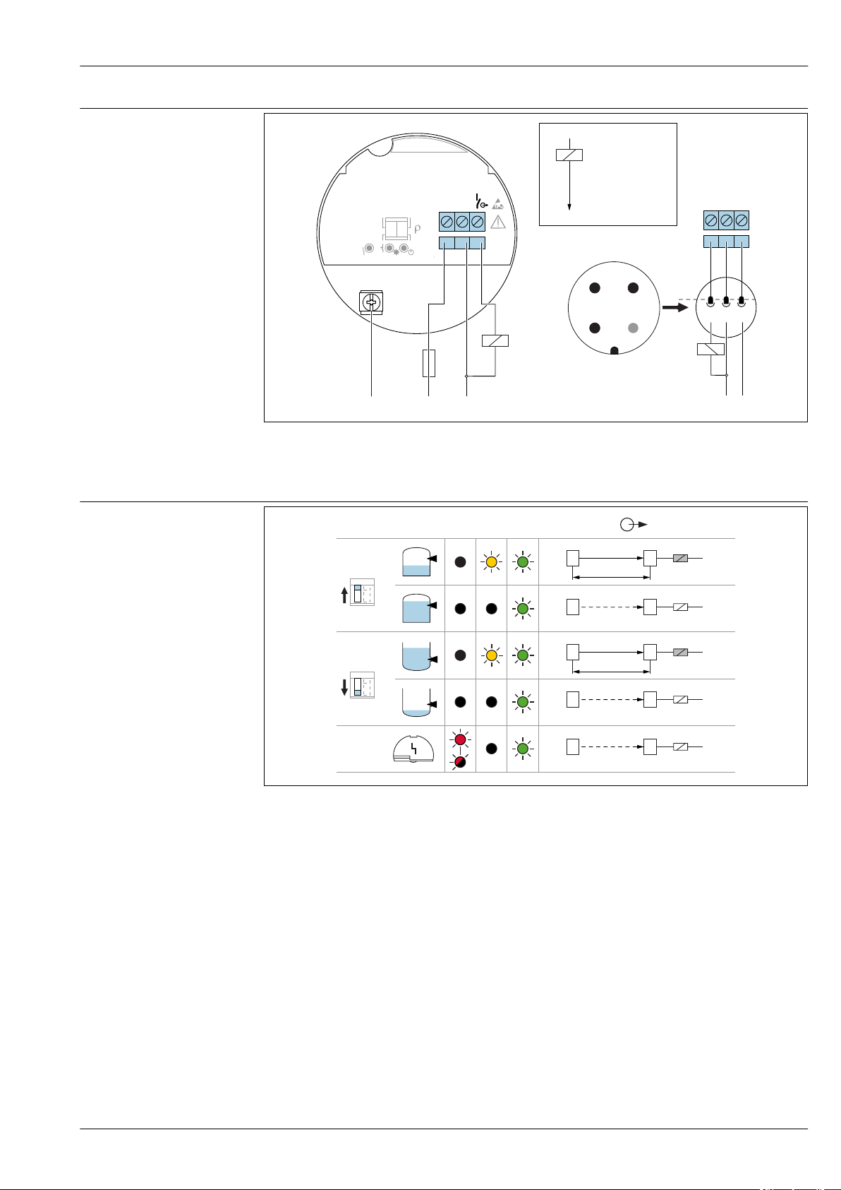
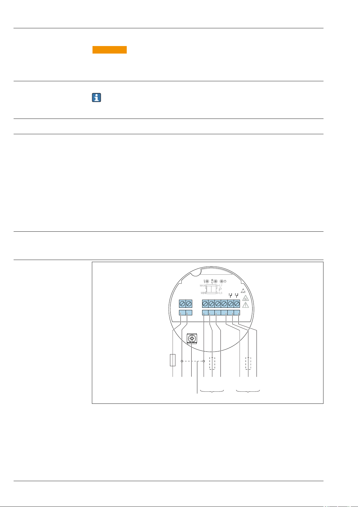
Terminal assignment
A0036056
2 Terminal assignment FEL42
A Terminal assignment at electronic insert
B Terminal assignment on connector M12
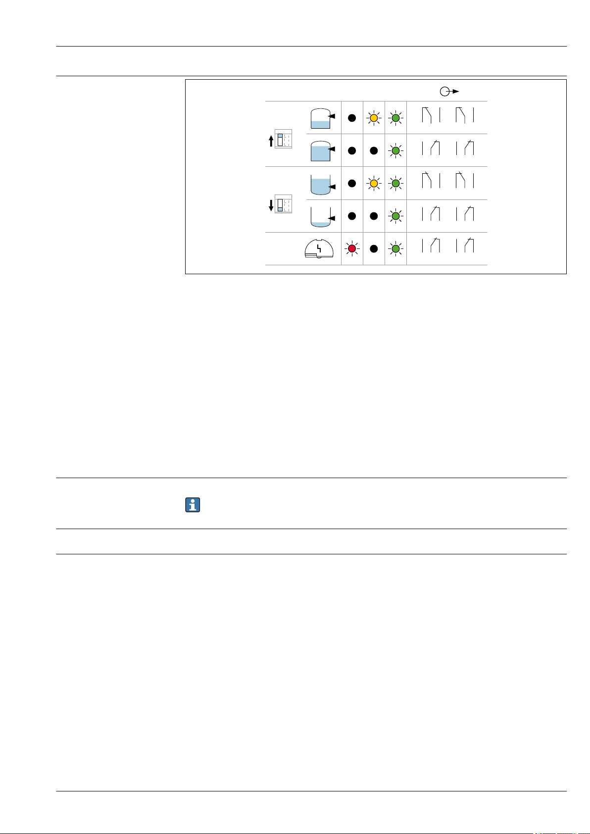
Behavior of the switch output and signaling
A0033508
3 FEL42 switching behavior, signaling LED
MAXDIP switch for setting the MAX safety
MIN DIP switch for setting the MIN safety
RD LED red for warning or alarm
YE LED yellow switch status
GN LED green operational status, device on
ILLoad current switched through
Endress+Hauser 7
Universal current connection with relay output (electronic insert FEL44)
• Switches the loads via 2 floating change-over contacts
• Two separate change-over contacts (DPDT)
Page 8
Liquiphant FTL41
L1
MIN
>0,7
MAX
>0,5
N
4
3 5
876
U = 19...55 V DC
U 19...253 V AC
~
~
!
0.5 A
1
2 2
L1
L+
NO NONC NCC CNL-PE
1 2 3 64 75 8
WARNING
L
In the event of an error, the electronic insert can exceed the limit temperature for touchable
surfaces, posing the risk of burns.
Do not touch the electronics in the event of an error!
‣
Supply voltage
Power consumption
Connectable load
Behavior output signal
U= 19 to 253 VAC / 19 to 55 V
DC
Observe the following in accordance with IEC/EN61010-1: Provide a suitable circuit breaker for
the device and limit the current to 500 mA, e. g. with the installation of a 0.5 A fuse (slowblow) in the phase (not the neutral conductor) of the power supply circuit.
P < 25 VA,< 1.3 W
Loads switched via 2 floating change-over contacts (DPDT)
• IAC ≤ 6 A (Ex de 4 A), U~ ≤ AC 253 V; P~ ≤ 1 500 VA, cos φ = 1, P~ ≤ 750 VA, cos φ > 0.7
• IDC ≤ 6 A (Ex de 4 A) to DC 30 V, IDC ≤ 0.2 A to 125 V
According to IEC 61010, the following applies: Total voltage from relay outputs and power supply
≤ 300 V
Electronic insert FEL42 DC PNP preferred for small DC load currents, e. g. for connection to a PLC.
Relay contact material: silver/nickel AgNi 90/10
When connecting a device with high inductivity, provide spark quenching to protect the relay
contact. A fine-wire fuse (depending on the connected load) protects the relay contact in the event of
a short-circuit.
Both relay contacts switch simultaneously.
• OK state: Relay energized
• Demand mode: Relay de-energized
• Alarm: Relay de-energized
Terminal assignment
A0036057
4 Universal current connection with relay output, electronic insert FEL44
1 When bridged, the relay output works with NPN logic
2 Connectable load
8 Endress+Hauser
Page 9
Liquiphant FTL41
3 54
3 54
6 87
6 87
3 54
33554
4
6 87
66887
7
MAX
RD YE GN
MIN
Behavior of the switch output and signaling
A0033513
5 FEL44 switching behavior, signaling LED
MAXDIP switch for setting the MAX safety
MIN DIP switch for setting the MIN safety
RD LED red for alarm
YE LED yellow switch status
GN LED green operational status, device on
Supply voltage
Power consumption
Behavior output signal
2-wire NAMUR > 2.2 mA/< 1.0 mA (electronic insert FEL48)
• For connection to the isolating switch repeater as per NAMUR (IEC 60947-5-6), e. g. Nivotester
FTL325N from Endress+Hauser
• Signal transmission H-L edge 2.2 to 3.8 mA/0.4 to 1.0 mA as per IEC 60947-5-6 (NAMUR) on
two-wire cabling
U = 8.2 V
P < 50 mW
• OK state: Current 2.2 to 3.8 mA
• Demand mode: Current 0.4 to 1.0 mA
• Alarm: Current 0.4 to 1.0 mA
DC
Observe the following in accordance with IEC/EN61010-1: Provide a suitable circuit breaker for
the device.
Endress+Hauser 9
Page 10
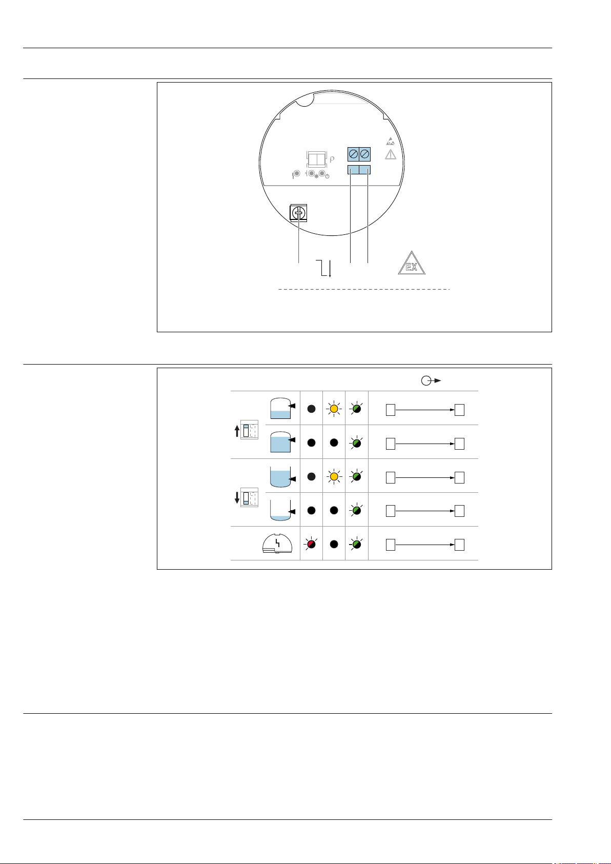
Terminal assignment
"
– +
MIN
MAX
>0,7
IEC 60947-5-6
8,2 V DC NAMUR
>0,5
1
2
!
L-
I
H
L
L+
.
-
1 2
MAX
RD YE GN
MIN
1
1
1
1
1
2
2
2
2
2
L+
L+
L+
L+
L+
2.2...3.8 mA
0.4...1.0 mA
2.2...3.8 mA
0.4...1.0 mA
< 1.0 mA
L-
L-
L-
L-
L-
Liquiphant FTL41
A0036058
6 2-wire NAMUR > 2.2 mA/< 1.0 mA, electronic insert FEL48
Behavior of the switch output and signaling
7 FEL48 switching behavior and signaling
MAXDIP switch for setting the MAX safety
MIN DIP switch for setting the MIN safety
RD LED red for alarm
YE LED yellow switch status
GN LED green operational status, device on
Reference operating conditions
Performance characteristics
• Ambient temperature: 23 °C (73 °F)
• Process temperature: 23 °C (73 °F)
• Density (water): 1 g/cm
• Medium viscosity: 1 mPa⋅s
3
• Process pressure: ambient pressure/unpressurized
• Sensor installation: vertically from above
• Density selection switch: > 0.7 g/cm3 (SGU)
• Switch direction of sensor: uncovered to covered
10 Endress+Hauser
A0037694
Page 11
Liquiphant FTL41
~13 (0.5)
~4 (0.16)
~12.5 (0.49)
D
A B C
D
D
0.5
1
1.5
2
-8
-6
-4
-2
0
2
4
6
[in]
[g/cm!]
C
A ( )ρ
B1
A1
-0.3
-0.2
-0.2
-0.1
0
0.2
0.2
[mm]
0.1
B ( )ρ
[ ]ρ
Taking the switch point into consideration
Typical switch points, depending on the orientation of the point level switch
(water +23 °C (+73 °F))
A0037915
8 Typical switch points. Unit of measurement mm (in)
A Installation from above
B Installation from below
C Installation from the side
D Switch point
Maximum measured error
Hysteresis
Non-repeatability
Influence of the process temperature
Influence of the process pressure
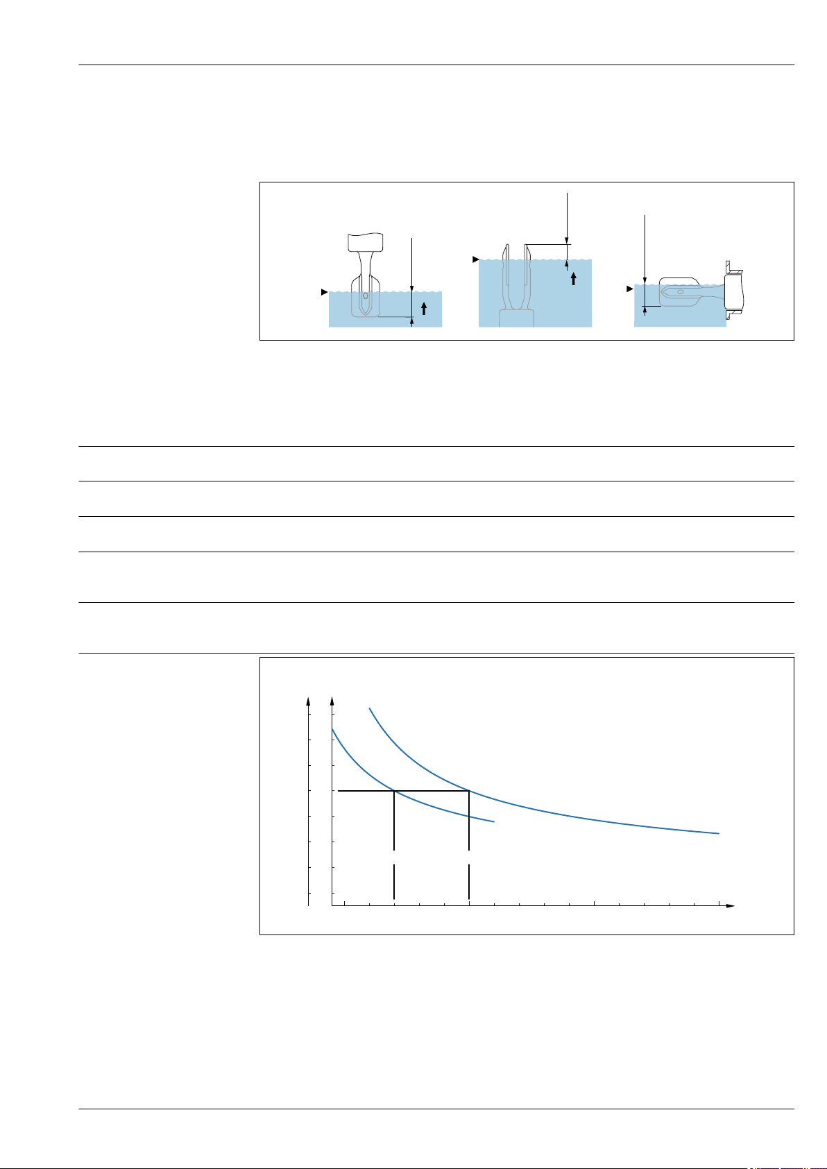
Influence of the density of the process medium (at room temperature and normal pressure)
At reference operating conditions: max. ±1 mm (0.04 in)
Typically 2.5 mm (0.1 in)
2 mm (0.08 in)
The switch point moves between +1.4 to –2.6 mm (+0.06 to –0.1 in) in the temperature range from
–50 to +150 °C (–58 to +302 °F)
The switch point moves between 0 to 2.6 mm (0 to 0.1 in) in the pressure range from
–1 to +64 bar (14.5 to 928 psi)
9 Switch point deviation over density
A Density switch setting (ρ) > 0.7
A1
B Density switch setting (ρ) > 0.5
B1
C Switch point deviation
Endress+Hauser 11
reference operating condition ρ = 1 g/cm
Reference operating condition ρ = 0.7 g/cm
3
A0037669
3
Page 12

Mounting location,
> 25 (0.98)
D
orientation
Density setting
• TK
, [mm/10 k]
type
• ρ > 0.7: –0.2
• ρ > 0.5: –0.2
• Pressure
, [mm/10 bar]
type
• ρ > 0.7: –0.3
• ρ > 0.5: –0.4
Mounting
Open the device only in a dry environment!
Liquiphant FTL41
10 Installation in any position in container, pipe or tank
Installation instructions Take viscosity into consideration
Low viscosity
11 Installation example for low-viscosity liquids. Unit of measurement mm (in)
D Diameter of installation socket: at least 50 mm (2.0 in)
Low viscosity, e. g. water: < 2 000 mPa⋅s
It is permitted to position the tuning fork within the installation socket.
A0036954
A0033297
12 Endress+Hauser
Page 13

Liquiphant FTL41
> 40 (1.57)
High viscosity
12 Installation example for a highly viscous liquid. Unit of measurement mm (in)
NOTICE
Highly viscous liquids may cause switching delays.
Make sure that the liquid can run off the tuning fork easily.
‣
Deburr the socket surface.
‣
High viscosity, e. g. viscous oils: < 10 000 mPa⋅s
The tuning fork must be located outside the installation socket!
A0037348
Avoiding buildup
13 Installation examples for a highly viscous process medium
• Use short installation sockets to ensure that the turning fork can project freely into the vessel.
• Install preferably flush-mounted on vessels or in pipes.
• Leave sufficient distance between the buildup expected on the tank wall and the tuning fork.
A0033239
Endress+Hauser 13
Page 14

Liquiphant FTL41
316L/G1
Take clearance into consideration
14 Take clearance into consideration
Allow sufficient space outside the tank for mounting, connection and settings involving the
electronic insert.
A0033236
Taking marking into account Align the tuning fork in accordance with the marking.
15 Markings for aligning the tuning fork
Using the marking, the tuning fork can be aligned in such a way that medium can run off easily and
buildup is avoided.
Markings may include the following:
• material specification, thread description or circle on hexagonal nut or welding neck
• Symbol II on rear of flange or Tri-Clamp
Installing in pipes
A0039125
A0034851
16 Installation in pipes
Flow velocities up to 5 m/s at a viscosity of 1 mPa⋅s and density of 1 g/cm3 (SGU)
Check the function in the event of other process medium conditions.
The flow will not be significantly impeded if the tuning fork is correctly aligned and the marking on
the adapter is pointing in the direction of flow.
The marking is visible when installed.
14 Endress+Hauser
Page 15

Liquiphant FTL41
316L
1.
2.
3
0.7 Nm
3
3.
Weld-in adapter with leakage hole
A0039230
17 Weld-in adapter with leakage hole
Weld in the welding neck in such a way that the leakage hole is pointing downwards. This enables
any leaks to be detected quickly.
Sliding sleeves
Aligning the cable entry
Special mounting instructions
See the "Accessories" section.
A0037347
18 Housing with external locking screw
Support the device
A0031874
19 Support in the event of dynamic load
Support the device in the event of severe dynamic load. Maximum lateral loading capacity of the pipe
extensions and sensors: 75 Nm (55 lbf ft).
Endress+Hauser 15
Page 16

Environment
T
a
T
p
+150
+302
+120
+248
+90
+194
+60
+140
+30
+86
0
32
-30
-22
-60
-76
70158
60140
50122
40104
3086
20
68
1050
032
[°C]
[°C]
[°F]
[°F]
Liquiphant FTL41
Ambient temperature range
–40 to +70 °C (–40 to +158 °F)
In the hazardous area, the permitted ambient temperature can be limited depending on the zones
and gas groups. Pay attention to the information in the Ex documentation (XA).
The minimum permitted ambient temperature of the plastic housing is limited to –20 °C (–4 °F); for
North America, "indoor use" applies.
Storage temperature
Humidity
Operating altitude
Climate class
Degree of protection
A0038718
20 For process temperature and FEL44 Tp > 90° max. load current 4 A
For outdoor operation in strong sunlight:
• Mount the device in the shade
• Avoid direct sunlight, particularly in warmer climatic regions
• Use a protective cover, which can be ordered as an accessory
–40 to +80 °C (–40 to +176 °F)
optional: –52 °C (–62 °F), –60 °C (–76 °F)
Operate up to 100 %. Do not open in a condensing atmosphere.
As per IEC 61010-1 Ed.3:
• Up to 2 000 m (6 600 ft) above sea level
• Can be extended to 3 000 m (9 800 ft) above sea level if overvoltage protection is used
As per IEC 60068-2-38 test Z/AD
For housing with electrical connection
Coupling M20, plastic
• Single-chamber plastic: IP66/67 NEMA Type 4X
• Single-chamber aluminum: IP66/68 NEMA Type 4X/6P
Coupling M20, nickel-plated brass
Single-chamber aluminum: IP66/68 NEMA Type 4X/6P
Coupling M20, 316L
Single-chamber aluminum: IP66/68 NEMA Type 4X/6P
16 Endress+Hauser
Page 17

Liquiphant FTL41
p
e
T
p
+150
+302
0
32
-40
-40
40580
032
[bar]
[°C]
[psi]
[°F]
Thread M20
• Single-chamber plastic: IP66/67 NEMA Type 4X
• Single-chamber aluminum: IP66/68 NEMA Type 4X/6P
Thread G ½
• Single-chamber plastic: IP66/67 NEMA Type 4X
• Single-chamber aluminum: IP66/68 NEMA Type 4X/6P
Thread NPT ½
Single-chamber plastic: IP66/67 NEMA Type 4X
Thread NPT ¾
Single-chamber aluminum: IP66/68 NEMA Type 4X/6P
M12 plug
• Single-chamber plastic: IP66/67 NEMA Type 4X
• Single-chamber aluminum: IP66/67 NEMA Type 4X
Vibration resistance
As per IEC60068-2-64-2009
a(RMS) = 50 m/s², f = 5 to 2 000 Hz , t = 3 axes x 2 h
Shock resistance
As per IEC60068-2-27-2008: 300 m/s² [=30 gn] + 18ms
Mechanical load Lateral loading capacity
Special mounting instructions
Electromagnetic compatibility
• Electromagnetic compatibility as per EN 61326 series and NAMUR recommendation EMC (NE21).
• The requirements of EN 61326-3-1 are fulfilled.
Process
Process temperature range
Thermal shock
Process pressure range
Pay attention to the pressure and temperature dependence (see the "Sensor process pressure range"
section )
–40 to +150 °C (–40 to +302 °F)
≤ 120 K/s
21 Process temperature FTL41
Endress+Hauser 17
A0038719
Page 18

WARNING
L
The maximum pressure for the measuring device is dependent on the lowest-rated element,
with regard to pressure, of the selected components. This means that it is necessary to pay
attention to the process connection as well as the sensor.
For pressure specifications, see the "Mechanical construction" section.
‣
The measuring device must be operated only within the specified limits!
‣
The Pressure Equipment Directive (2014/68/EU) uses the abbreviation "PS". The abbreviation "PS"
‣
corresponds to the MWP (maximum working pressure) of the measuring device.
Approved pressure values of the flanges at higher temperatures, taken from the following standards:
• pR EN 1092-1: 2005 With regard to its stability-temperature property, the material 1.4435 is
identical to 1.4404, which is classed as 13E0 in EN 1092-1 Tab. 18. The chemical composition of
the two materials can be identical.
• ASME B 16.5
• JIS B 2220
In each case, the lowest value from the derating curves of the device and the selected flange applies.
Process pressure range of the sensors
PN: 40 bar (580 psi)
Test pressure Overpressure
PN = 40 bar (580 psi): Test pressure = 1.5 · PN max. 60 bar (870 psi) dependent on the process
connection selected
The device function is limited during the pressure test.
The mechanical integrity is guaranteed at pressures up to 1.5 times the process nominal pressure
PN.
Liquiphant FTL41
Density
Pressure tightness
• Switch position > 0.7 g/cm3 = order configuration
Standard setting for liquids with a density > 0.7 g/cm
• Switch position > 0.5 g/cm3 = can be set via DIP switch
For liquids with a density > 0.5 g/cm3 to < 0.8 g/cm
• Order option: 0.4 g/cm
For liquids with a density > 0.4 g/cm3 to < 0.6 g/cm
If this option has been selected, the density setting is then always set to 0.4 g/cm3. The setting can
no longer be changed.
Up to vacuum
In vacuum evaporation systems, the density of the liquids can drop to a very low value: select
density setting 0.4.
Mechanical construction
For the dimensions, see the Product Configurator: www.endress.com
Search for product → click "Configuration" to the right of the product image → after
configuration click "CAD"
The following dimensions are rounded values. For this reason, they may deviate slightly from
the dimensions given on www.endress.com.
Design, dimensions Device height
The device height is made up of the following components:
• Housing including cover
• Pipe extension, short pipe or compact version
• Process connection
The individual heights of the components can be found in the following sections:
• Calculate device height and add the individual heights of the components
• Take the installation clearance into consideration (space that is required to install the device)
3
3
3
3
18 Endress+Hauser
Page 19

Liquiphant FTL41
C
B
B
B
A
F
D
E
!94 (3.7)
101 (3.98)
!101 (3.98)
103 (4.06)
A0036789
22 Components for calculating the device height
A Housing
B Process connections
C Process connections
D Pipe extension
E Short pipe
F Installation clearance
Dimensions Housing
All housings can be aligned. On metal housings, the alignment of the housing can also be fixed by
means of the locking screw.
23 Single chamber housing, plastic
A0038712
24 Single chamber housing, aluminum, coated
Endress+Hauser 19
A0038713
Page 20

Liquiphant FTL41
!101 (3.98)
118 (4.65)
L
25 Single chamber housing, aluminum, coated, suitable for Ex d/XP zone
Ground terminal
• Ground terminal inside the housing, max. conductor cross-section 2.5 mm2 (14 AWG)
• Ground terminal outside the housing, max. conductor cross-section 4 mm2 (12 AWG)
• Safety extra-low voltage used to supply power to electronic inserts; do not connect protective
ground.
Cable glands
Cable diameter
• Nickel-plated brass: dia. 7 to 10.5 mm (0.28 to 0.41 in)
• Plastic: dia. 5 to 10 mm (0.2 to 0.38 in)
At delivery
• One fitted cable gland
• One cable gland sealed with dummy plug
The relay electronics additionally include a second cable gland (not fitted) with delivery.
Exceptions: For Ex d/XP, only threaded insertions are permitted.
For Japanese Ex d approval, a special cable gland is enclosed.
A0035590
Probe design
Compact
• Material: 316L
• Sensor length L: Dependent on process connection
See section on process connections: Thread G, ASME B1.20.3 MNPT, EN10226 R, tri-clamp
26 Compact, sensor length L
Version: Probe design pipe extension
Material: 316L, sensor lengths L: 117 to 2 000 mm or 4.6 to 78.7 in
A0036848
20 Endress+Hauser
Page 21

Liquiphant FTL41
L
3
L
L
1 2
L
3
L
L
1 2
40 (1.57)
17 (0.67)
17.2 (0.68)
1.5 (0.06)
14 (0.55)
A0036860
27 Pipe extension, sensor length L
1 G ¾, G 1
2 NPT ¾, NPT 1, R ¾, R 1
3 Flange, tri-clamp
Version: Probe design short pipe
Material: 316L, sensor length L: Dependent on process connection
• Flange = 115 mm (4.53 in)
• Thread G ¾ = 115 mm (4.53 in)
• Thread G 1 = 118 mm (4.65 in)
• Thread NPT, R = 99 mm (3.9 in)
• Tri-clamp = 115 mm (4.53 in)
Endress+Hauser 21
A0036861
28 Short pipe, sensor length L
1 G ¾, G 1
2 NPT ¾, NPT 1, R ¾, R 1
3 Flange, tri-clamp
Tuning fork
A0038269
29 Tuning fork. Unit of measurement mm (in)
Page 22

Process connections
50.5 (2.19)
32
66.5 (2.62)
41
80 (3.15)
61.3 (2.41)
50.5 (2.19)
32
66.5 (2.62)
41
69 (2.72)
50.5 (1.99)
32
50.5 (2.19)
71.5 (2.81)
50.5 (2.19)
69 (2.72)
41
Thread ISO228 G for installing in weld-in adapter
G ¾, G 1 suitable for installation in weld-in adapter
• Material: 316L
• Pressure rating, temperature: ≤ 40 bar (580 psi), ≤ 100 °C (212 °F)
• Pressure rating, temperature: ≤ 25 bar (363 psi), ≤ 150 °C (302 °F)
• Weight: 0.2 kg (0.44 lb)
• Accessory: weld-in adapter
The weld-in adapter is not included in the scope of delivery.
Liquiphant FTL41
30 Thread ISO228 G ¾. Unit of
measurement mm (in)
Thread ISO228 G with flat seal
32 Thread ISO228 G ¾. Unit of
measurement mm (in)
Thread ASME B1.20.3, MNPT
A0035549
31 Thread ISO228 G 1. Unit of
measurement mm (in)
A0035549
33 Thread ISO228 G 1. Unit of
measurement mm (in)
A0035551
A0037756
A0038274
34 Thread ASME B1.20.3, MNPT ¾. Unit of
measurement mm (in)
35 Thread ASME B1.20.3, MNPT 1. Unit of
measurement mm (in)
22 Endress+Hauser
A0038275
Page 23

Liquiphant FTL41
32
50.5 (2.19)
66 (2.62)
50.5 (2.19)
69 (2.72)
41
50.5 (1.99)
66.5 (2.62)
64 (2.52)
66.5 (2.62)
66.5 (2.62)
Thread EN10226, R
A0038272
36 Thread EN10226, R ¾. Unit of
measurement mm (in)
37 Thread EN10226, R 1. Unit of
measurement mm (in)
Tri-Clamp
Version ISO2852 DN25-38 (1 to 1-½), DIN32676 DN25-40
• Material: 316L
• Pressure rating: ≤ 25 bar (363 psi)
• Temperature: ≤ 150 °C (302 °F)
• Weight: 0.1 (0.22)
The maximum temperature and the maximum pressure are dependent on the clamping ring
and the seal used. The lowest value applies in each case.
A0035555
38 Tri-Clamp 1 to 1-½. Unit of
measurement mm (in)
39 Tri-Clamp 2. Unit of measurement mm (in)
A0038273
A0037671
Sensor dimensions in the case of flanges
A0035554
40 Example with flange. Unit of measurement mm (in)
ASME B16.5 flanges, RJF
Pressure rating Type Material Weight
kg (lb)
Cl.300 NPS 2" 316/316L 3.2 (7.06)
Cl.300 NPS 4" 316/316L 11.5 (25.6)
Endress+Hauser 23
Page 24

Liquiphant FTL41
EN flanges EN 1092-1, A
Pressure rating Type Material Weight
kg (lb)
PN6 DN32 316L (1.4404) 1.2 (2.65)
PN6 DN40 316L (1.4404) 1.4 (3.09)
PN6 DN50 316L (1.4404) 1.6 (3.53)
PN10/16 DN80 316L (1.4404) 4.8 (10.58)
PN10/16 DN100 316L (1.4404) 5.6 (12.35)
PN25/40 DN25 316L (1.4404) 1.3 (2.87)
PN25/40 DN32 316L (1.4404) 2.0 (4.41)
PN25/40 DN40 316L (1.4404) 2.4 (5.29)
PN25/40 DN50 316L (1.4404) 3.2 (7.06)
PN25/40 DN65 316L (1.4404) 4.3 (9.48)
PN25/40 DN80 316L (1.4404) 5.9 (13.01)
PN25/40 DN100 316L (1.4404) 7.5 (16.54)
PN40 DN50 316L (1.4404) 3.2 (7.06)
EN flanges EN 1092-1, B1
Pressure rating Type Material Weight
kg (lb)
PN6 DN32 316L (1.4404) 1.2 (2.65)
PN6 DN50 316L (1.4404) 1.6 (3.53)
PN10/16 DN100 316L (1.4404) 5.6 (12.35)
PN25/40 DN25 316L (1.4404) 1.4 (3.09)
PN25/40 DN50 316L (1.4404) 3.2 (7.06)
PN25/40 DN80 316L (1.4404) 5.9 (13.01)
JIS flanges B2220
Pressure rating Type Material Weight
kg (lb)
10K 10K 25A 316L (1.4404) 1.3 (2.87)
10K 10K 40A 316L (1.4404) 1.5 (3.31)
10K 10K 50A 316L (1.4404) 1.7 (3.75)
Process connection, sealing surface
• Thread ISO228, G
• Thread ASME, MNPT
• Thread EN10226, R
• Flange ASME B16.5, RF (Raised Face)
• Flange EN1092-1, Form A
• Flange EN1092-1, Form B1
• Flange JIS B2220, RF (Raised Face)
• Flange HG/T20592, RF (Raised Face), pending
• Flange HG/T20615, RF (Raised Face), pending
Other
24 Endress+Hauser
Page 25

Liquiphant FTL41
Weight
Materials Materials in contact with process
See the specific section.
• Process connection: 316L (1.4404 or 1.4435)
• Pipe extension: 316L (1.4404 or 1.4435)
• Flat seal for process connection G ¾ or G 1: Fiber-reinforced elastomer seal, asbestos-free as per
DIN 7603
• Flanges, mechanical construction
• Tuning fork: 316L (1.4435)
Seals
Seal included in delivery:
Metrical threads G ¾, G 1 standard, flat seal as per DIN7603
Seal not included in delivery:
• Tri-Clamp
• Flanges
• R and NPT thread
• Metrical threads G ¾, G 1 for installation in weld-in adapter
Materials not in contact with process
Aluminum housing
• Housing: Alu-EN AC 44300
• Blind cover: Alu-EN AC 44300
• Cover sealing materials: HNBR
• TAG plate: Plastic film, stainless steel or provided by the customer
• Cable glands M20: Select material (stainless steel, nickel-plated brass, polyamide)
Plastic housing
• Housing: PBT/PC
• Blind cover: PBT/PC
• Cover seal: EPDM
• Potential equalization: 316L
• Seal under potential equalization: EPDM
• Plug: PBT-GF30-FR
• M20 cable gland: PA
• Seal on plug and cable gland: EPDM
• Adapter as replacement for cable glands: 316L
• TAG plate: Plastic film, metal or provided by the customer
Surface roughness
The roughness of the surface in contact with the process is Ra < 3.2 µm (126 μin).
Operability
Operation concept
Endress+Hauser 25
Operation with DIP switches on the electronic insert
Page 26

Elements on the electronic
L1
MIN
>0,7
MAX
>0,5
N
4
3 5 876
U = 19...55 V DC
U 19...253 V AC
~
~
1 2 3 64 75 8
1
2
3
4
5
6
7
A B
MAX
MIN
ρ > 0.7
ρ > 0.5
insert
Liquiphant FTL41
A0039317
41 Example electronic insert FEL44
1 LED red, for warning or alarm
2 LED yellow, switch status
3 LED green, operational status (LED green lights up = device on)
4 DIP switch to set the density to 0.7 or 0.5
5 Relay contact terminals
6 Power supply terminals
7 DIP switch for setting MAX/MIN safety
Terminals
Terminals for cable cross-section up to 2.5 mm2 (14 AWG). Use ferrules for the wires.
Local operation Operation at electronic insert
MAX/MIN fail-safe mode
42 Switch position on the electronic insert for fail-safe mode MAX/MIN
A MAX (maximum fail-safe mode)
B MIN (minimum fail-safe mode)
• Minimum/maximum quiescent current safety can be switched at the electronic insert
• MAX = maximum safety: The output switches to demand mode when the tuning fork is covered,
used e. g. for overfill protection
• MIN = minimum safety: The output switches to demand mode when the tuning fork is uncovered,
used e. g. to prevent pumps from running dry
Density switchover
A0033470
43 Switch position on the electronic insert for density
Factory setting density: 0.7
26 Endress+Hauser
A0033471
Page 27

Liquiphant FTL41
CE mark
RCM-Tick marking
• Switch position > 0.7 g/cm3 = order configuration
Standard configuration for liquids with a density > 0.7 g/cm
3
• Switch position > 0.5 g/cm3 = can be adjusted via DIP switch
For liquids with a density > 0.5 g/cm3 to < 0.8 g/cm
• Order option: 0.4 g/cm
3
For liquids with a density > 0.4 g/cm3 to density < 0.6 g/cm
3
3
If the option has been selected, the density setting is then always set to 0.4 g/cm3. The setting can
no longer be changed.
Certificates and approvals
The certificates and approvals currently available can be accessed via the
• Product Configurator
• Endress+Hauser website: www.endress.com → Downloads.
The measuring system complies with the statutory requirements of the applicable EC Directives.
These are listed in the corresponding EC Declaration of Conformity along with the standards applied.
Endress+Hauser confirms successful testing of the device by affixing to it the CE mark.
The supplied product or measuring system meets the ACMA (Australian Communications and Media
Authority) requirements for network integrity, interoperability, performance characteristics as well
as health and safety regulations. Here, especially the regulatory arrangements for electromagnetic
compatibility are met. The products are labelled with the RCM- Tick marking on the name plate.
Ex approval
Overfill protection
Marine approvals
CRN approval
A0029561
All explosion protection data is listed in separate documentation which is available from the
download area. The Ex documentation is supplied as standard with all Ex-systems.
Before mounting the device, observe the documentation from the WHG approvals (German Federal
Water Act).
Approved for overfill protection and leakage detection.
Ordering information: Product Configurator, order code for "Additional approval", option "LD"
• ABS (American Bureau of Shipping), option "LF"
• GL (Germanischer Lloyd)/DNV (Det Norske Veritas), option "LJ"
• LR (Lloyd's Register) marine approval, option "LG"
• BV (Bureau Veritas) marine approval, option "LH"
Ordering information: Product Configurator, order code for "Additional approval", for option see
items listed
Versions with a CRN approval (Canadian Registration Number) are listed in the corresponding
registration documents. CRN-approved devices are marked with a registration number.
Any restrictions regarding the maximum process pressure values are listed on the CRN certificate.
Ordering information: Product Configurator, order code for "Service", option "17"
Test reports Test, report, declaration
The following documentation can be ordered:
Endress+Hauser 27
Page 28

Liquiphant FTL41
• Inspection certificate 3.1, EN10204 (material certificate, wetted parts)
• ASME B31.3 Process Piping, declaration
• Pressure test, internal procedure, test report
• Helium leak test, internal procedure, test report
• Material identification check (PMI), internal procedure (wetted parts), test report
Service
• Cleaned of oil+grease (wetted)
• PWIS-free (paint-wetting impairment substances)
• Switching delay setting to be spec.
• Setting for MIN safety mode
• Default density setting > 0.4 g/cm
• Default density setting > 0.5 g/cm
• Product documentation on paper (test, certificate, declaration available for selection)
3
3
Pressure Equipment Directive
Process seal as per ANSI/ISA
12.27.01
China RoHS symbol
RoHS
Pressure equipment with allowable pressure ≤ 200 bar (2 900 psi)
Pressure instruments with a flange and threaded boss that do not have a pressurized housing do not
fall within the scope of the Pressure Equipment Directive, irrespective of the maximum allowable
pressure.
Reasons:
According to Article 2, point 5 of EU Directive 2014/68/EU, pressure accessories are defined as
"devices with an operational function and having pressure-bearing housings".
If a pressure instrument does not have a pressure-bearing housing (no identifiable pressure chamber
of its own), there is no pressure accessory present within the meaning of the Directive.
North American practice for the installation of process seals. In accordance with ANSI/ISA 12.27.01,
Endress+Hauser devices are designed as either single seal or dual seal devices with a warning
message. This allows the user to waive the use of – and save the cost of installing – an external
secondary process seal in the protective conduit as required in ANSI/NFPA 70 (NEC) and CSA 22.1
(CEC). These devices comply with the North-American installation practice and provide a very safe
and cost-effective installation for pressurized applications with hazardous process media. More
information is provided in the Safety Instructions (XA) for the relevant device.
Aluminum and plastic housings are approved as single-seal devices.
China RoHS 1, law SJ/T 11363-2006: The measuring system complies with the substance
restrictions of the Restriction on Hazardous Substances Directive (RoHS).
The measuring system complies with the substance restrictions of the Restriction on Hazardous
Substances Directive 2011/65/EU (RoHS 2).
Additional certification EAC conformity
The measuring system meets the legal requirements of the applicable EAC guidelines. These are
listed in the corresponding EAC Declaration of Conformity together with the standards applied.
Endress+Hauser confirms successful testing of the device by affixing to it the EAC mark.
ASME B 31.3
Design and materials in accordance with ASME B31.3. The welds are through-penetration welded
and meet the requirements of the ASME Boiler and Pressure Vessel Code, Section IX and EN ISO
15614-1.
28 Endress+Hauser
Page 29

Liquiphant FTL41
140 (5.51) 32 (1.26)
115 (4.53)
122 (4.8)
Ordering information
Detailed ordering information is available from the following sources:
• In the Product Configurator on the Endress+Hauser website: www.endress.com → Click "Corporate"
→ Select your country → Click "Products" → Select the product using the filters and search field →
Open product page → The "Configure" button to the right of the product image opens the Product
Configurator.
• Endress+Hauser sales center: www.addresses.endress.com
Product Configurator - the tool for individual product configuration
• Up-to-the-minute configuration data
• Depending on the device: Direct input of measuring point-specific information such as
measuring range or operating language
• Automatic verification of exclusion criteria
• Automatic creation of the order code and its breakdown in PDF or Excel output format
• Ability to order directly in the Endress+Hauser Online Shop
TAG Measuring point (tag)
The device can be ordered with a tag name.
Position of the tag name
In the additional specification, select:
• Tag plate, stainless steel
• Plastic film
• Supplied plate
Definition of the tag name
In the additional specification, specify:
3 lines, each containing up to maximum 18 characters
The specified tag name appears on the selected label and/or the RFID TAG.
Accessories
Device-specific accessories Weather protection cover for single-compartment housing, metal
• Material: plastic
• Order number: 71438291
44 Weather protection cover for single-compartment housing, metal. Unit of measurement mm (in)
Plug-in jack
The plug-in jacks listed are suitable for use in the temperature range
–25 to +70 °C (–13 to +158 °F).
Plug-in jack M12 IP69
• Terminated at one end
• Elbowed 90°
• 5 m (16 ft) PVC cable (orange)
• Slotted nut 316L (1.4435)
• Body: PVC (orange)
• Order number: 52024216
A0038280
Endress+Hauser 29
Page 30

27.5
(1.08)
40³
(1.57)
45 Plug-in jack M12 IP69. Unit of measurement mm (in)
27.5
(1.08)
40³
(1.57)
22 (0.87)
18 (0.71)
G 1 A
(1 NPT)
G 1½ A
(1½ NPT)
M6 (3x)
1
M6 (3x)
19 (0.75)
19 (0.75)
55
55
Plug-in jack M12 IP67
• Elbowed 90°
• 5 m (16 ft)PVC cable (gray)
• Slotted nut Cu Sn/Ni
• Body: PUR (blue)
• Order number: 52010285
Liquiphant FTL41
A0023713
Sliding sleeves for unpressurized operation
46 Plug-in jack M12 IP67. Unit of measurement mm (in)
Switch point, infinitely adjustable.
47 Sliding sleeves for unpressurized operation. Unit of measurement mm (in)
1 pe = 0 bar (0 psi)
G 1, DIN ISO 228/I
• Material: 1.4435 (AISI 316L)
• Weight: 0.21 kg (0.46 lb)
• Order number: 52003978
• Order number: 52011888, approval: with inspection certificate EN 10204 - 3.1 material
NPT 1, ASME B 1.20.1
• Material: 1.4435 (AISI 316L)
• Weight: 0.21 kg (0.46 lb)
• Order number: 52003979
• Order number: 52011889, approval: with inspection certificate EN 10204 - 3.1 material
A0022292
A0037666
30 Endress+Hauser
Page 31

Liquiphant FTL41
G 1 A
(1 NPT)
G 1½A
(1½ NPT)
ø60 (2.36)
~72 (2.83)
~70 76(2. )
2 (0.08)
2 (0.08)
ø60 (2.36)
18 71(0. )
5050
G 1½, DIN ISO 228/I
• Material: 1.4435 (AISI 316L)
• Weight: 0.54 kg (1.19 lb)
• Order number: 52003980
• Order number: 52011890, approval: with inspection certificate EN 10204 - 3.1 material
NPT 1½, ASME B 1.20.1
• Material: 1.4435 (AISI 316L)
• Weight: 0.54 kg (1.19 lb)
• Order number: 52003981
• Order number: 52011891, approval: with inspection certificate EN 10204 - 3.1 material
High pressure sliding sleeves
• Switch point, infinitely adjustable
• For use in hazardous areas,
• Seal package made of graphite
• For G 1, G 1½: seal included in delivery
48 High pressure sliding sleeves. Unit of measurement mm (in)
G 1, DIN ISO 228/I
• Material: 1.4435 (AISI 316L)
• Weight: 1.13 kg (2.49 lb)
• Order number: 52003663
• Order number: 52011880, approval: with inspection certificate EN 10204 - 3.1 material
G 1, DIN ISO 228/I
• Material: AlloyC22
• Weight: 1.13 kg (2.49 lb)
• Approval: with inspection certificate EN 10204 - 3.1 material
• Order number: 71118691
NPT 1, ASME B 1.20.1
• Material: 1.4435 (AISI 316L)
• Weight: 1.13 kg (2.49 lb)
• Order number: 52003667
• Order number: 52011881, approval: with inspection certificate EN 10204 - 3.1 material
NPT 1, ASME B 1.20.1
• Material: AlloyC22
• Weight: 1.13 kg (2.49 lb)
• Approval: with inspection certificate EN 10204 - 3.1 material
• Order number: 71118694
G 1½, DIN ISO 228/1
• Material: 1.4435 (AISI 316L)
• Weight: 1.32 kg (2.91 lb)
• Order number: 52003665
• Order number: 52011882, approval: with inspection certificate EN 10204 - 3.1 material
A0037667
Endress+Hauser 31
Page 32

Liquiphant FTL41
G 1½, DIN ISO 228/1
• Material: AlloyC22
• Weight: 1.32 kg (2.91 lb)
• Approval: with inspection certificate EN 10204 - 3.1 material
NPT 1½, ASME B 1.20.1
• Material: 1.4435 (AISI 316L)
• Weight: 1.32 kg (2.91 lb)
• Order number: 52003669
• Order number: 52011883, approval: with inspection certificate EN 10204 - 3.1 material
NPT 1½, ASME B 1.20.1
• Material: AlloyC22
• Weight: 1.32 kg (2.91 lb)
• Approval: with inspection certificate EN 10204 - 3.1 material
• Order number: 71118695
32 Endress+Hauser
Page 33

Liquiphant FTL41
Supplementary documentation
The certificates and approvals currently available can be accessed via the
• Product Configurator
• Endress+Hauser website: www.endress.com → Downloads.
Special documentation
Device-dependent supplementary documentation
• TI00426F: Welding neck and flanges (overview)
• SD01622F: Welding neck (assembly manual)
Document type: Operating Instructions (BA)
Installation and initial commissioning ‒ contains all functions in the operating menu that are
required for a typical measuring task. Functions beyond this scope are not included.
BA01893F
Document type: Brief Operating Instructions (KA)
Quick guide to the first measured value ‒ includes all essential information from the incoming
acceptance to the electrical connection.
KA01411F
Document type: Safety Instructions, certificates
Depending on the approval, Safety Instructions are also supplied with the device, e. g. XA. This
documentation is an integral part of the Operating Instructions.
The nameplate indicates the Safety Instructions (XA) that are relevant to the device.
Endress+Hauser 33
Page 34

Page 35

Page 36

*71440553*
71440553
www.addresses.endress.com
 Loading...