

Page 1
TI01148F/00/EN/03.16
71325893
Products Solutions Services
Technical Information
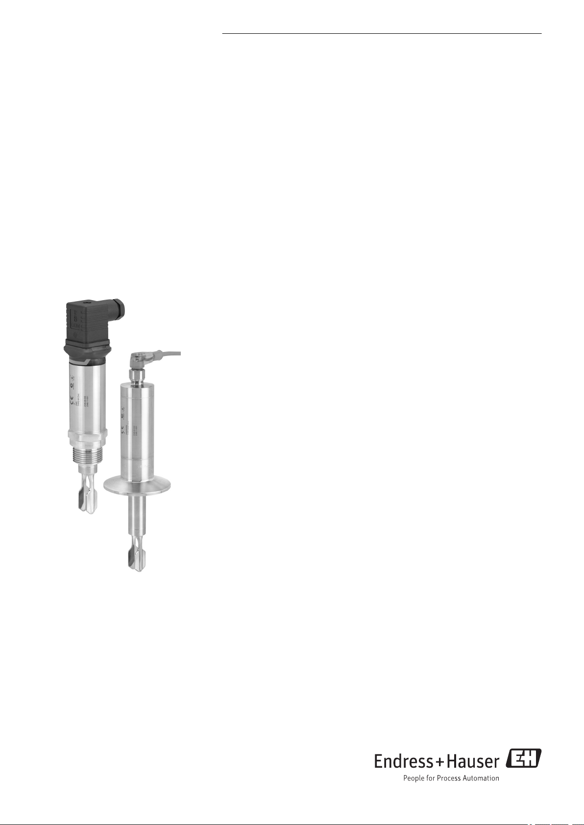
Liquiphant FTL33
Vibronic
Point level switch for liquids
in the food sector
Application
The Liquiphant FTL33 is a point level switch for universal use in all liquids. It is used
preferably in storage tanks, mixing vessels and pipes, where the internal and
external hygiene requirements are particularly stringent.
Ideal for applications in which float switches or conductive, capacitance and optical
sensors have been used up to now. The Liquiphant FTL33 also works in areas where
these measuring principles are not suitable due to conductivity, buildup, turbulence,
flow conditions or air bubbles.
The Liquiphant FTL33 can be used for process temperatures up to:
• 100 °C (212 °F), CIP-capable
• 150 °C (302 °F), CIP- and SIP-capable
Your benefits
• 3-A and EHEDG certificates
• CIP and SIP cleanability guaranteed up to 150 °C (302 °F)
continuous temperature
• All-metal separation, no plastics in the process
• Robust stainless steel housing, optionally available with M12x1 connector with
IP69 protection (optional)
• External function test with test magnet
• Onsite function check possible thanks to LED indication
• Compact design for easy installation even in confined conditions or hard-to-access
areas
Page 2

Table of contents
Liquiphant FTL33
Document information ....................... 3
Document conventions .......................... 3
Function and system design ................... 4
Measuring principle ............................ 4
Measuring system ............................. 4
Input ..................................... 5
Measured variable ............................. 5
Measuring range .............................. 5
Output ................................... 5
Switch output ................................ 5
Operating modes .............................. 5
Power supply .............................. 5
Supply voltage ............................... 5
Power consumption ............................ 5
Current consumption ........................... 5
Residual ripple ............................... 5
Electrical connection ........................... 5
Cable entry ................................. 9
Cable specification ............................ 10
Overvoltage protection ......................... 10
Performance characteristics .................. 11
Reference operating conditions ................... 11
Switch point ................................ 11
Hysteresis ................................. 11
Non-repeatability ............................ 11
Influence of ambient temperature ................. 11
Influence of medium temperature .................. 11
Influence of medium pressure .................... 11
Switching delay .............................. 11
Switch-on delay ............................. 11
Measuring frequency .......................... 11
Measured error .............................. 11
Installation ............................... 12
Orientation ................................ 12
Installation instructions ........................ 12
Length of connecting cable ...................... 14
Environment .............................. 15
Ambient temperature range ..................... 15
Storage temperature .......................... 15
Climate class ............................... 15
Altitude ................................... 15
Degree of protection .......................... 16
Shock resistance ............................. 16
Vibration resistance ........................... 16
Cleaning .................................. 16
Electromagnetic compatibility .................... 16
Reverse polarity protection ...................... 16
Short-circuit protection ........................ 16
Process .................................. 17
Process temperature range ...................... 17
Process pressure range ......................... 17
Density ................................... 17
State of aggregation ........................... 17
Viscosity .................................. 17
Solids contents .............................. 17
Lateral loading capacity ........................ 17
Mechanical construction .................... 18
Design .................................... 18
Connector ................................. 19
Tuning fork ................................ 19
Sensor type ................................ 20
Weight ................................... 24
Materials .................................. 24
Surface roughness ............................ 25
Operability ............................... 26
LED display ................................ 26
Function test with test magnet .................... 26
Certificates and approvals ................... 27
CE mark ................................... 27
EAC conformity .............................. 27
RCM-Tick marking ............................ 27
Approval .................................. 27
Hygienic compatibility ......................... 27
Hygiene approval ............................ 28
Overfill prevention ............................ 28
CRN approval ............................... 28
Inspection certificates .......................... 28
Manufacturer declarations ...................... 28
Pressure Equipment Directive .................... 28
Other standards and guidelines ................... 28
Ordering information ...................... 29
Ordering information .......................... 29
Services (optional) ............................ 29
Accessories ............................... 29
Process adapter M24 .......................... 29
Weld-in adapter ............................. 30
Slotted nut ................................. 30
Plug-in jack, cable ............................ 31
Additional accessories ......................... 32
Supplementary documentation ............... 33
Operating Instructions ......................... 33
Additional documentation ...................... 33
Certificates ................................. 33
2 Endress+Hauser
Page 3
Liquiphant FTL33
DANGER
WARNING
CAUTION
NOTICE
Document information
Document conventions Safety symbols
Symbol Meaning
Electrical symbols
A0011189-EN
A0011190-EN
A0011191-EN
A0011192-EN
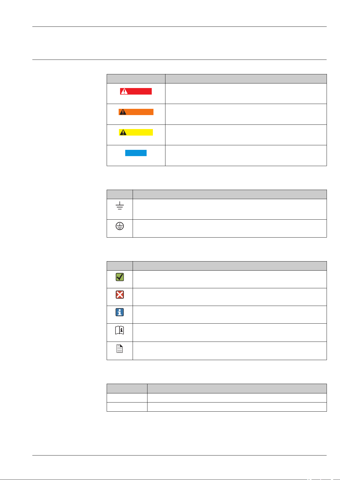
DANGER!
This symbol alerts you to a dangerous situation. Failure to avoid this situation
will result in serious or fatal injury.
WARNING!
This symbol alerts you to a dangerous situation. Failure to avoid this situation
can result in serious or fatal injury.
CAUTION!
This symbol alerts you to a dangerous situation. Failure to avoid this situation
can result in minor or medium injury.
NOTE!
This symbol contains information on procedures and other facts which do not
result in personal injury.
Symbol Meaning
Ground connection
A grounded terminal which, as far as the operator is concerned, is grounded via a grounding
A0011200
system.
Protective ground connection
A terminal which must be connected to ground prior to establishing any other connections.
A0011199
Symbols for certain types of information
Symbol Meaning
Permitted
Indicates procedures, processes or actions that are permitted.
A0011182
Forbidden
Indicates procedures, processes or actions that are forbidden.
A0011184
Tip
Indicates additional information.
A0011193
Reference to documentation
Refers to the corresponding device documentation.
A0011194
Reference to page
Refers to the corresponding page number.
A0011195
Symbols in graphics
Symbol Meaning
1, 2, 3 ... Item numbers
A, B, C, ... Views
Endress+Hauser 3
Page 4
Function and system design
2
1
3
Liquiphant FTL33
Measuring principle
Measuring system
A piezoelectric drive causes the tuning fork of the Liquiphant FTL33 to vibrate at its resonance
frequency. When the tuning fork is immersed in a liquid, its intrinsic frequency changes due to the
change in density of the surrounding medium. The electronics system in the point level switch
monitors the resonance frequency and indicates whether the tuning fork is vibrating in air or is
covered by liquid.
A signal is output via the DC-PNP or AC/DC electrical connection.
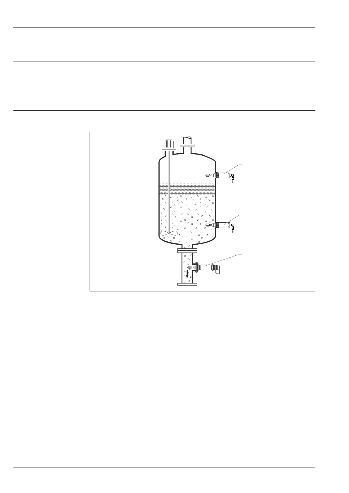
The measuring system consists of a Liquiphant FTL33 point level switch, e.g. for connection to
programmable logic controllers (PLC), a mini-contactor or solenoid valve.
1 Overfill prevention or upper level detection MAX (maximum safety)
2 Lower level detection MIN (minimum safety)
3 Lower level detection MIN, e.g. dry running protection for pump
A0020911
4 Endress+Hauser
Page 5

Liquiphant FTL33
Input
Measured variable
Measuring range
Switch output
Operating modes
Density
> 0.7 g/cm³ (optionally available: > 0.5 g/cm³)
Output
Switching behavior: On/Off
Function
3-wire DC-PNP:
Positive voltage signal at the switch output of the electronics (PNP), switching capacity 200 mA
2-wire AC/DC:
Load switching in the power supply line, switching capacity 250 mA
The device has two operating modes: maximum safety (MAX) and minimum safety (MIN).
By choosing the corresponding operating mode, the user ensures that the device also switches in a
safety-oriented manner even in an alarm condition, e.g. if the power supply line is disconnected.
• Maximum safety (MAX)
The device keeps the electronic switch closed as long as the liquid level is below the fork. Sample
application: overfill prevention
• Minimum safety (MIN)
The device keeps the electronic switch closed as long as the fork is immersed in liquid. Sample
application: Dry running protection for pumps
The electronic switch opens if the limit is reached, if a fault occurs or the power fails (quiescent
current principle).
Supply voltage
Power consumption
Current consumption
Residual ripple
Electrical connection
Power supply
DC-PNP:
AC/DC:
DC-PNP:
AC/DC:
DC-PNP:
AC/DC:
DC-PNP:
AC/DC:
Two electronic versions and three different connections are available for the device.
• Electronic version 3-wire DC-PNP with connection; M12 plug, valve plug or cable
• Electronic version 2-wire AC/DC with connection; valve plug or cable
A fine-wire fuse is necessary for operation: 500 mA slow-blow.
Electronic version 3-wire DC-PNP
3-wire DC-PNP is preferably used in conjunction with programmable logic controllers (PLC), DI
modules as per EN 61131-2. Positive signal at the switch output of the electronics (PNP).
Voltage source: non-hazardous contact voltage or Class 2 circuit (North America).
10 to 30 V DC, 3-wire
20 to 253 V AC/DC, 2-wire
< 975 mW
< 850 mW
< 15 mA
< 3.8 mA
5 Vss 0 to 400 Hz
—
Endress+Hauser 5
Page 6
Liquiphant FTL33
0.5A
L– L+
2
1
3
4
K
0.5A
L–
L+
2
1
3
4
K
1
21
2
1
41
4
0.5A
L– L+
2
1
3
4
K1
K2
1
2
1
4
4
1
1 2
21
41
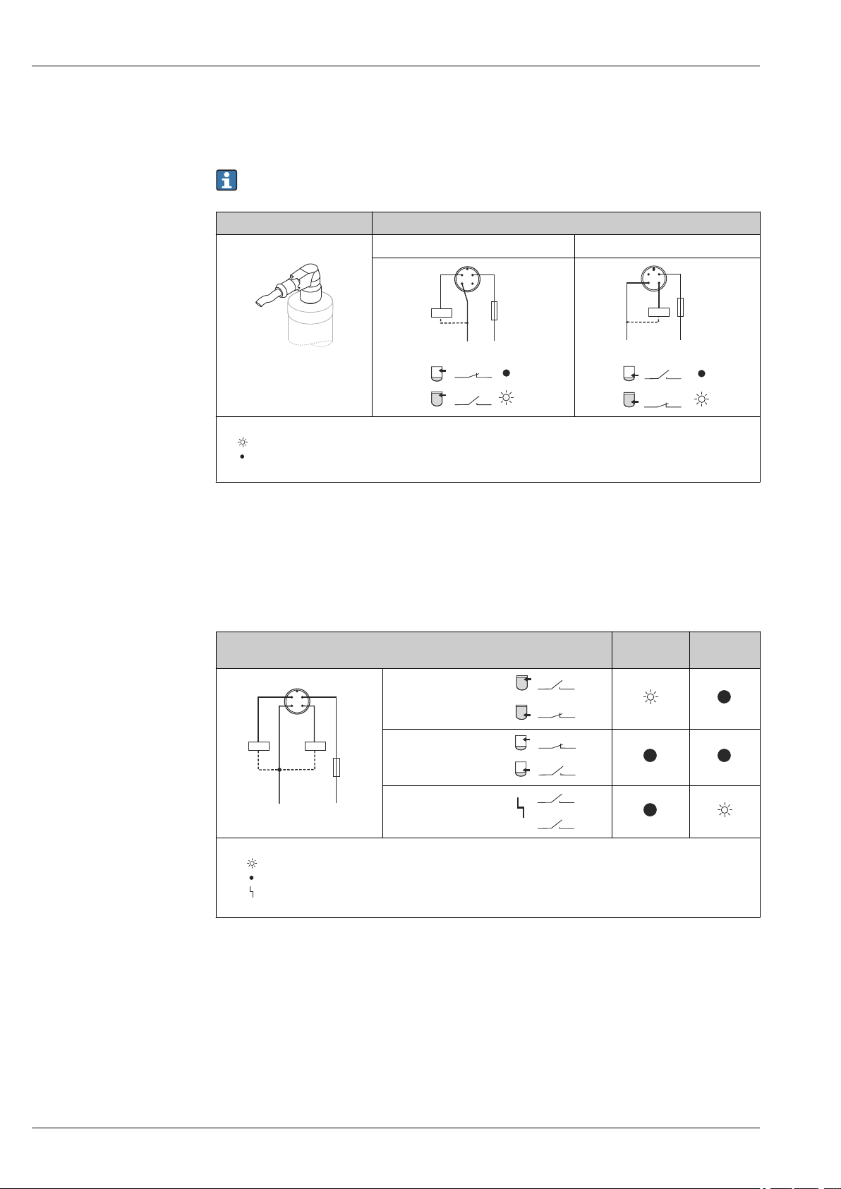
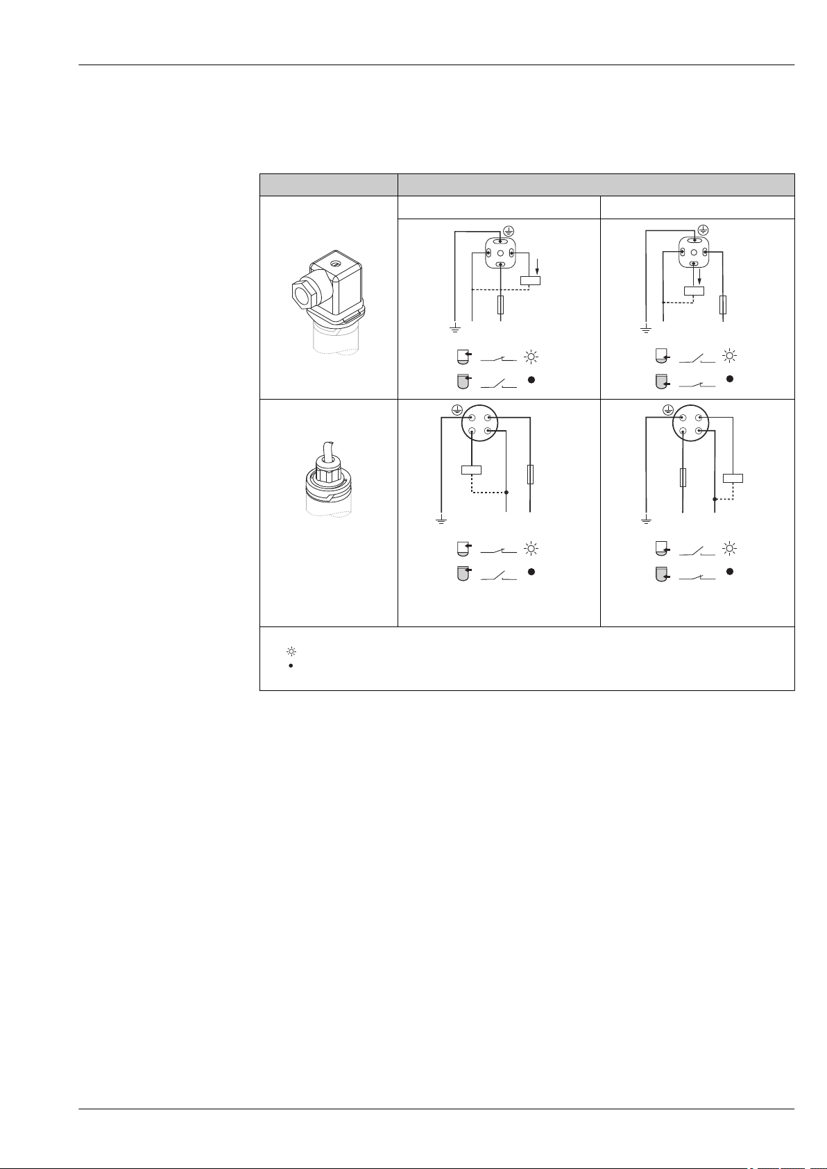
Connection with M12 plug
Depending on the analysis of the switch outputs, the device works in the MAX (maximum safety) or
MIN (minimum safety) mode.
A cable is optionally available for order, see "Accessories" section → 31.
3-wire DC-PNP Operating mode
M12 connector MAX MIN
A0022901
SymbolsKDescription
Yellow LED (ye) lit
Yellow LED (ye) not lit
external load
Function monitoring with M12 connector
Using a two-channel analysis, function monitoring of the sensor can be implemented in addition to
level monitoring, e.g. per relay switch, PLC, AS-i Bus I/O module, …).
When both outputs are connected, the MIN and MAX outputs assume opposite states when the
device is operating fault-free (XOR). In the event of an alarm condition or a line break, both outputs
are deenergized.
Connection with 3-wire DC-PNP for function monitoring based on XOR logic
Sensor covered
Sensor exposed
Fault
A0022917
Symbols
K1 / K2
Description
LED lit
LED not lit
Fault or warning
external load
Yellow LED
(ye)
Red LED
(rd)
6 Endress+Hauser
Page 7
Liquiphant FTL33
1
3
0.5A
L–
L+
2
K
+
–
L–
L+
3
0.5A
1
2
K
+
–
3
23
2
2323
0.5A
1
2
3
L–
L+
K
+
L+
0.5A
K
1
2
3
L–
+
3
23
2
2323
Connection with valve plug or cable
Depending on the assignment of the connector or the wiring of the cable, the device works in either
the MAX or MIN operating mode.
3-wire DC-PNP Operating mode
Valve plug MAX MIN
A0022900
Cable (cannot be
dismantled)
Core colors:
1 = BK (black)
2 = GR (gray)
3 = BN (brown)
Ground = GNYE (greenyellow)
SymbolsKDescription
Yellow LED (ye) lit
Yellow LED (ye) not lit
external load
A0022902
Endress+Hauser 7
Page 8
Liquiphant FTL33
2.7
2.5
2.3
2.1
1.9
1.7
1.5
1.3
1.1
0.9
0.7
0.5
20 24 27 43 48 53 60 110 121 207 230 253
P/S
U
P1
P2
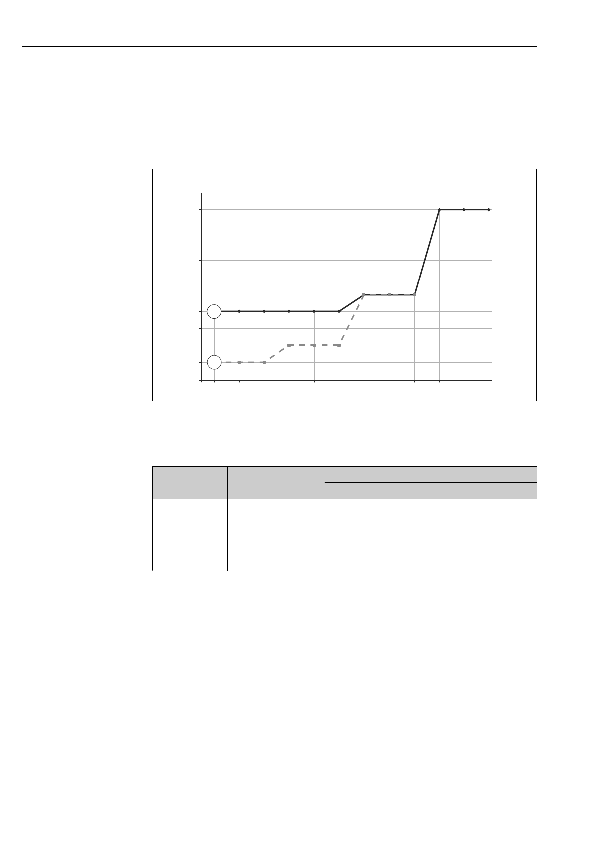
Electronic version 2-wire AC/DC
The load is switched via an electronic switch directly in the power supply circuit. Always connect in
series with a load!
Not suitable for connection to low-voltage PLC inputs!
Selection tool for relays
1 Minimum rated power of the load
P/S Rated power in [W] / [VA]
U Operating voltage in [V]
Item Supply voltage
P1
AC mode
P2
DC mode
24 V
110 V
230 V
24 V
48 V
60 V
min max
> 1.3 VA
> 1.5 VA
> 2.5 VA
> 0.7 W
> 0.9 W
> 1.5 W
Rated power
< 6 VA
< 27.5 VA
< 57.5 VA
< 6 W
< 12 W
< 15 W
Relays with a lower rated power can be operated by means of an RC module connected in parallel
(optional).
A0023486
8 Endress+Hauser
Page 9
Liquiphant FTL33
3
0.5A
1
K
>20 V
L1/L+ N/L–
2
0.5A
1
K
>20 V
L1/L+ N/L–
1313
1
21
2
3
L1/L+
0.5A
K
>20 V
1
2
N/L–
1
L1/L+
0.5A
K
2
3
N/L–
>20 V
1313
1
21
2
A
B
C
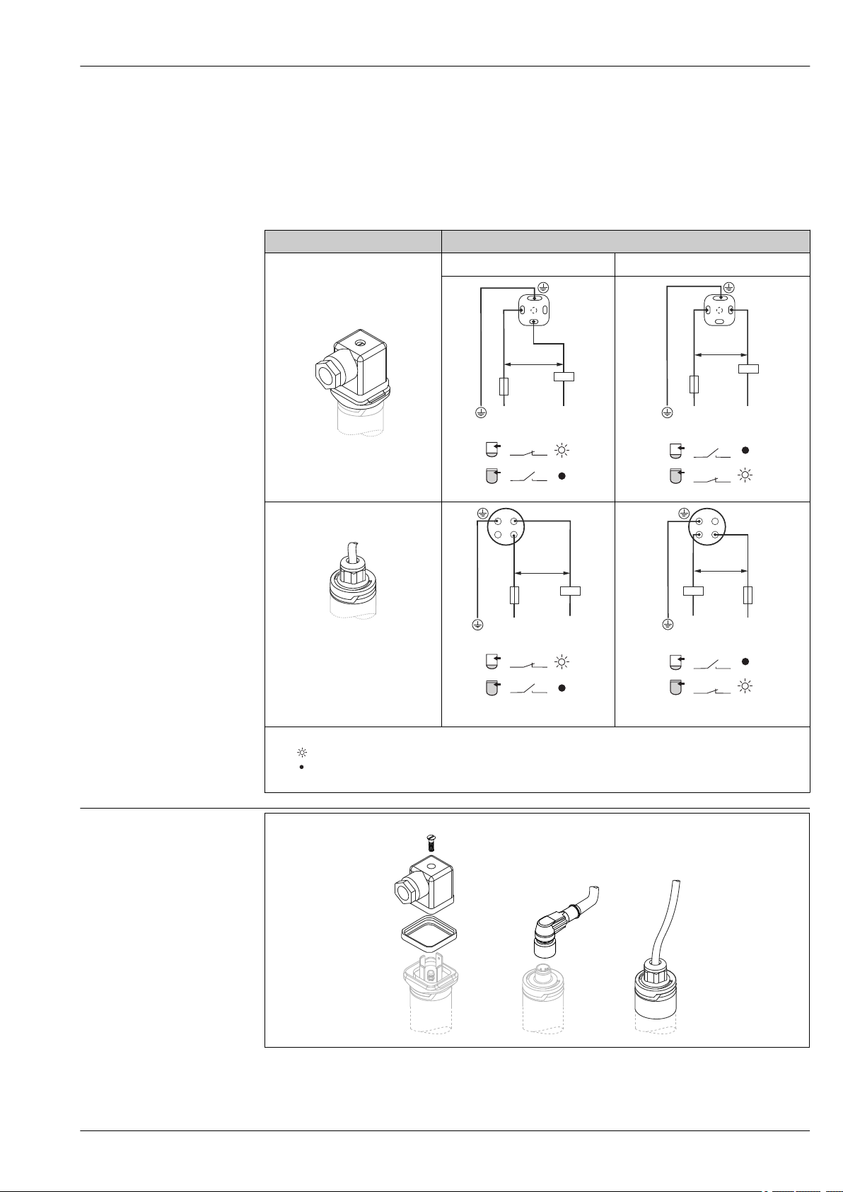
Connection with valve plug or cable
Depending on the assignment of the connector or the wiring of the cable, the device works in either
the MAX or MIN operating mode.
When the cable is wired, one wire of the cable does not have any function in each of the operating
modes (brown in the case of MIN, and gray in the case of MAX). The cable with no function must be
secured against inadvertent contact.
2-wire AC/DC Operating mode
Valve plug MAX MIN
Cable entry
Cable (cannot be dismantled)
Core colors:
1 = BK (black)
2 = GR (gray)
3 = BN (brown)
Ground = GNYE (green-yellow)
SymbolsKDescription
Yellow LED (ye) lit
Yellow LED (ye) not lit
external load
A0022900
A0022902
A0021219
A0021418
A0022161
A0021418
A0021220
A0021420
A0022225
A0021420
Endress+Hauser 9
A0020928
A Valve plug (M16x1.5; NPT ½"; QUICKON)
B M12 connector
C Cable 5 m (16 ft); secured in place on delivery and cannot be disassembled
Page 10

Liquiphant FTL33
Cable specification
Overvoltage protection
• Valve plug
– Cable cross-section: max. 1.5 mm2 (AWG 16)
– Ø 3.5 to 8 mm (0.14 to 0.26 in)
• M12 connector: IEC 60947-5-2
• Cable (3LPE)
– Cable cross-section: 0.75 mm2 (AWG 20)
– Ø 6 to 8 mm (0.24 to 0.31 in)
– Material: PUR
Overvoltage category II
10 Endress+Hauser
Page 11

Liquiphant FTL33
Performance characteristics
Reference operating conditions
Switch point
Hysteresis
Non-repeatability
Influence of ambient temperature
Influence of medium temperature
Influence of medium pressure
Ambient temperature: +25 °C (+77 °F)
Process pressure: 1 bar (14.5 psi)
Fluid: Water (density: approx. 1 g/cm³, viscosity 1 mm2/s)
Medium temperature: 25 °C (77 °F)
Density setting: > 0.7 g/cm³
Switching time delay: Standard (0.5 s, 1 s)
13 mm (0.51 in)±1 mm
max. 3 mm (0.12 in)
±1 mm (0.04 in) in accordance with DIN 61298-2
Negligible
–25 µm (984 µin)/°C
–20 µm (787 µin)/bar
Switching delay
Switch-on delay
Measuring frequency
Measured error
• 0.5 s when tuning fork is covered
• 1.0 s when tuning fork is uncovered
• Optionally available: 0.2 s; 1.5 s or 5 s (when the tuning fork is covered and uncovered)
max. 3 s
approx. 1 100 Hz in air
In event of device change: ±2 mm (0.08 in) as per DIN 61298-2
Endress+Hauser 11
Page 12

Installation
1
2
2
3
A
~30 (1.2)
A
A
~10.5(0.4)
~13 (0.5)
Liquiphant FTL33
Orientation
The point level switch can be installed in any position in a vessel, pipe or tank. Foam formation does
not affect the function.
2 Installation options
1 Overfill prevention or upper level detection
2 Lower level detection
3 Dry running protection for pump
Installation instructions Switch point
The switch point (A) on the sensor depends on the orientation of the point level switch (water
+25 °C (+77 °F), 1 bar (14.5 psi).
3 Vertical and horizontal orientation, dimensions in mm (in)
A0023118
A0020734
12 Endress+Hauser
Page 13

Liquiphant FTL33
A
B
116.8 (4.6)
13 (0.51)
25 (0.98)
128 (5.04)
C
C
ø >50 (2.0)
<5 m/s (16 ft/s)
ø >10 (0.4)
Short tube version
The use of the short tube ensures that the switch point is at the same level as in the previous
Liquiphant FTL260 and FTL330 models when an identical thread is selected. In this way, the device
can be replaced quickly and easily. (Applies for process connections G 1" weld-in adapter for flushmounted installation and MNPT 1")
A0022122
Dimensions mm (in)
A Liquiphant FTL33 with short tube
B Liquiphant FTL260 or FTL330
C Switch point
Installation in pipes
During installation, pay attention to the position of the fork in order to minimize turbulence in the
pipe.
A0021357
Dimensions mm (in)
Endress+Hauser 13
A0022268
Page 14

Liquiphant FTL33
G1/2
316L
Installation in vessels
If installed horizontally, pay attention to the position of the tuning fork to ensure that the liquid can
drip off easily.
The electrical connection, e.g. M12 connector, should be pointing down with the cable. This can
prevent moisture from penetrating.
Length of connecting cable
A0021034
4 Position of the fork in the case of horizontal installation in a vessel
Distance from wall
Ensure that there is sufficient distance between the expected buildup on the tank wall and the fork.
Recommended distance from wall ≥10 mm (0.39 in).
A0022272
• to1 000 m (3 281 ft)
• max. 25 Ω/wire, total capacitance < 100 nF
14 Endress+Hauser
Page 15

Liquiphant FTL33
0 +50
+80
+100
–40
+32 +122
+176
+212
–40
–40
+70
[°C]
+158
[°F]
0
+32
[°C]
[°F]
+50
+122
T
a
T
P
T
a
T
p
1
2
–40
0 +50 +100 +150
–40
+32 +122 +212 +302
–40
–40
+70
[°C]
–40
+158
[°F]
0
+32
[°C]
[°F]
+50
+122
T
a
T
P
1
2
T
a
T
p
+90
+194
Environment
Ambient temperature range
–40 to +70 °C (–40 to +158 °F)
5 Derating curve: 100 °C (212 °F)
1 I
2 I
Ta Ambient temperature range
Tp Process temperature
: 200 mA (DC-PNP), 250 mA (AC/DC)
max
: 150 mA (DC-PNP), 150 mA (AC/DC)
max
A0022002
A0020869
6 Derating curve: 150 °C (302 °F)
1 I
Storage temperature
Climate class
Altitude
2 I
Ta Ambient temperature range
Tp Process temperature
–40 to +85 °C (–40 to +185 °F)
DIN EN 60068-2-38/IEC 68-2-38: test Z/AD
Up to 2 000 m (6 600 ft) above sea level
Endress+Hauser 15
: 200 mA (DC-PNP), 250 mA (AC/DC)
max
: 150 mA (DC-PNP), 150 mA (AC/DC)
max
Page 16

Liquiphant FTL33
Degree of protection
Shock resistance
Vibration resistance
Cleaning
Electromagnetic compatibility
Reverse polarity protection
• IP65/67 NEMA Type 4X Enclosure (M12 connector)
• IP66/68/69
• IP65 NEMA Type 4X Enclosure (valve plug)
• IP66/68 NEMA Type 4X/6P Enclosure (cable)
1) The IP69K protection class is defined in accordance with DIN 40050 Part 9. This standard was withdrawn
on 01.11.2012 and replaced by DIN EN 60529. The name of the IP protection class changed to IP69 as
part of this.
1)
NEMA Type 4X/6P Enclosure (M12 plug for metallic housing cover)
a = 300 m/s² = 30 g, 3 planes x 2 directions x 3 shocks x 18 ms,
as per test Ea, prEN 60068-2-27:2007
a(RMS) = 50 m/s², ASD = 1.25 (m/s²)²/Hz, f = 5 to 2000 Hz, t = 3 x 2 h,
as per test Fh, EN 60068-2-64:2008
Resistant to typical cleaning agents from the outside. Passed Ecolab test.
Electromagnetic compatibility in accordance with all relevant requirements of the EN 61326 series
and NAMUR recommendation EMC (NE21). For details, refer to the EC Declaration of Conformity.
The EC Declaration of Conformity is available in the Download Area of the Endress+Hauser website:
www.endress.com → Downloads.
2-wire AC/DC
• AC mode: the device has reverse polarity protection.
• DC mode: in the event of reverse polarity the maximum safety mode is always detected. Check the
wiring and perform a function check before commissioning. The device is not damaged in the
event of reverse polarity.
3-wire DC-PNP
Integrated. In the event of reverse polarity, the device is deactivated automatically.
Short-circuit protection
2-wire AC/DC
During switching the sensor checks whether a load, e.g. relay or contactor, is present (load check). If
an error occurs, the sensor is not damaged.
Smart monitoring: normal operation is resumed once the error is fixed.
3-wire DC-PNP
Overload protection/short-circuit protection at I > 250 mA; the sensor is not destroyed.
Intelligent monitoring: Testing for overload at intervals of approx. 1.5 s; normal operation resumes
once the overload/short-circuit has been rectified.
16 Endress+Hauser
Page 17

Liquiphant FTL33
Process
Pay attention to the pressure and temperature derating depending on the selected process
connection → 20.
Process temperature range
Process pressure range
Density
State of aggregation
Viscosity
Solids contents
Lateral loading capacity
–40 to +100 °C (–40 to +212 °F)
–40 to +150 °C (–40 to +302 °F)
Max. –1 to +40 bar (–14.5 to +580 psi)
> 0.7 g/cm³ (optionally available: > 0.5 g/cm³)
Liquid
1 to 10 000 mPa·s, dynamic viscosity
ø < 5 mm (0.2 in)
Lateral loading capacity of the tuning fork: maximum 200 N
Endress+Hauser 17
Page 18

Mechanical construction
A
B
C
D
Liquiphant FTL33
Design
Various versions of the point level switch are available, the features of which can be selected to suit
your user needs.
The versions can be selected via the product structure in the Product Configurator, see the "Ordering
information" section → 29. Examples can be seen in the following diagram:
A0022077
Versions
Electrical connection Valve plug
Housing (sensor design)
for process
temperatures up to:
Sensor type Compact version Short tube version Compact version Short tube version
A B C D
Cable
(cannot be
dismantled)
100 °C (212 °F) 100 °C (212 °F) 150 °C (302 °F) 150 °C (302 °F)
Examples
M12 connector
for housing cover
IP66/68/69
M12 connector
for housing cover
IP65/67
Detailed information on the process connections is provided in the "Sensor type" section
→ 20.
Information on the short tube version is provided in the "Installation instructions" section
→ 13.
18 Endress+Hauser
Page 19

Liquiphant FTL33
40 (1.6)
51.5 (2.0)
45 (1.8)
45.5 (1.8)
27.5 (1.1)
25 (1.0)
39 (1.5)
27.5 (1.1)
25 (1.0)
39 (1.5)
27.8 (1.1)
45.3 (1.8)
8 (0.31)
13.7 (0.54)
38 (1.5)
14 (0.55)
3 (0.12)
ø17.1 (0.67)
Connector
Dimensions
Dimensions mm (in)
The following graphics illustrate the connectors together with the suitable housing covers on the
housing of the point level switch.
Electrical connection with housing cover Designation
A
A
A0021859
A0021858
B
B
A:
Valve plug M16, NPT ½"
for housing cover: PPSU plastic
B:
Valve plug QUICKON
for housing cover: PPSU plastic
A0021860
A:
M12 connector
for housing cover: 316L (1.4404),
IP66/68/69
B:
M12 connector
for housing cover: PPSU plastic
(IP65/67)
A0021857
Captive cable
with housing cover: PPSU plastic
Tuning fork
A0021692
Dimensions
Dimensions mm (in)
A0022250
Endress+Hauser 19
Page 20

Liquiphant FTL33
16 (0.63)
63.9 (2.52)
112 (4.41)*
136.6 (5.38)**
38 (1.5)
ø31.5
(1.24)
32
16 (0.63)
103.3 (4.07)
151.4 (5.96)*
176 (6.93)**
ø17.1
(0.7)
ø31.5
(1.24)
38 (1.5)
32
Sensor type
Dimensions
Dimensions mm (in)
The total dimensions of the device can vary depending on the connector selected. To determine the
total dimensions, please refer also to the "Electrical connection" section → 19.
Information on the following tables
• Meaning of symbols:
* Dimension for process temperature max. 100 °C (212 °F)
** Dimension for process temperature max. 150 °C (302 °F)
• If several versions have the same dimensions, one example of the compact version and one
example of the short tube version is given.
• The versions in the second column refer to the process connections in the product structure.
Information on 3-A and EHEDG-approved weld-in adapters can be found in the "Weld-in
adapters, process adapters and flanges" documentation, TI00426F/00.→ 33.
Dimensions Version Description
WBJ Thread ISO 228 G ½"
• Material: 316L
• Scope of delivery: flat seal (FA)
• Pressure and temperature (maximum):
+40 bar (+580 psi) at +150 °C (+302 °F)
W5J Thread ISO 228 G ¾"
for flush-mounted installation in weld-in adapter
• Material: 316L
• Scope of delivery: flat seal (FA)
Accessory: weld-in adapter
A0021787
7 Compact version, example G ½"
– Scope of delivery: seal (VMQ)
– Pressure and temperature (maximum):
+25 bar (+362 psi) at +150 °C (+302 °F)
+40 bar (+580 psi) at +100 °C (+212 °F)
– Approval:
EHEDG (Ra 1.5 µm (59 µin), 0.76 µm (30 µin))
3-A (Ra 0.76 µm (30 µin))
A0021883
8 Short tube version, example G ½"
20 Endress+Hauser
Page 21

Liquiphant FTL33
47.9 (1.89)
77.4 (3.05)
136.6 (5.38)*
151.4 (5.96)**
38 (1.5)
ø31.5
(1.24)
32
87.3 (3.44)
116.8 (4.6)
176 (6.93)*
190.8 (7.51)**
ø17.1
(0.7)
38 (1.5)
ø31.5
(1.24)
32
63.9 (2.52)
112 (4.41)*
136.6 (5.38)**
38 (1.5)
ø31.5
(1.24)
32
47.9 (1.89)
103.3 (4.07)
151.4 (5.96)*
176 (6.93)**
38 (1.5)
ø17.1
(0.7)
ø31.5
(1.24)
32
87.3 (3.44)
Dimensions Version Description
WSJ Thread ISO 228 G 1"
for flush-mounted installation in weld-in adapter
• Material: 316L
• Scope of delivery: flat seal (FA)
Accessory: weld-in adapter
– Scope of delivery: seal (VMQ)
– Pressure and temperature (maximum):
+25 bar (+362 psi) at +150 °C (+302 °F)
+40 bar (+580 psi) at +100 °C (+212 °F)
– Approval:
EHEDG (Ra 1.5 µm (59 µin), 0.76 µm (30 µin))
3-A (Ra 0.76 µm (30 µin))
A0022008
9 Compact version
A0022007
10 Short tube version
Dimensions Version Description
VAJ Thread ASME MNPT ½"
VBJ Thread ASME MNPT ¾"
• Material: 316L
• Pressure and temperature (maximum):
+40 bar (+580 psi) at +150 °C (+302 °F)
The dimensions apply for MNPT ½" and MNPT ¾".
A0021788
11 Compact version, example MNPT ¾"
12 Short tube version, example MNPT ¾"
Endress+Hauser 21
A0021895
Page 22

Dimensions Version Description
66.4 (2.61)
47.9 (1.89)
112 (5.38)*
136.6 (5.38)**
38 (1.5)
ø31.5
(1.24)
32
98.3 (3.87)
116.8 (4.57)
176 (6.93)*
190.8 (7.51)**
ø17.1
(0.7)
38 (1.5)
ø31.5
(1.24)
32
64.9 (2.56)
112 (4.41)*
136.6 (5.38)**
38 (1.5)
ø31.5
(1.24)
32
104.3 (4.12)
151.4 (5.96)*
176 (6.93)**
ø17.1
(0.7)
ø31.5
(1.24)
38 (1.5)
32
VCJ Thread ASME MNPT 1"
• Material: 316L
• Pressure and temperature (maximum):
+40 bar (+580 psi) at +150 °C (+302 °F)
A0022330
13 Compact version
Liquiphant FTL33
A0022331
14 Short tube version
Dimensions Version Description
X2J Thread M24x1.5
for flush-mounted installation in adapter
• Material: 316L
• Scope of delivery: O-ring (EPDM)
Accessories: process adapter
– Scope of delivery: O-ring (EPDM)
– Temperature (maximum):
130 °C (266 °F), for information on the pressure
ratings, see the "Accessories" section → 29
Accessory: weld-in adapter
A0021870
15 Compact version
– Scope of delivery: O-ring (EPDM)
– Pressure and temperature (maximum):
+25 bar (+362 psi) at +150 °C (+302 °F)
– Approval:
EHEDG (Ra 1.5 µm (59 µin), 0.76 µm (30 µin))
3-A (Ra 0.76 µm (30 µin))
16 Short tube version
22 Endress+Hauser
A0021894
Page 23

Liquiphant FTL33
47.9 (1.89)
112 (4.41)*
136.6 (5.38)**
38 (1.5)
ø31.5
(1.24)
87.3 (3.44)
151.4 (5.96)*
176 (6.93)**
38 (1.5)
ø31.5
(1.24)
ø17.1
(0.7)
47.9 (1.89)
112 (4.41)*
136.6 (5.38)**
38 (1.5)
ø31.5
(1.24)
87.3 (3.44)
151.4 (5.96)*
176 (6.93)**
ø17.1
(0.7)
ø31.5
(1.24)
38 (1.5)
Dimensions Version Description
1GJ DIN 11851 DN25 PN40 (dairy pipe)
1HJ DIN 11851 DN32 PN40 (dairy pipe)
1JJ DIN 11851 DN40 PN40 (dairy pipe)
• Material: 316L
• Scope of delivery: excluding slotted nut, excluding
seal
• Pressure and temperature (maximum):
+25 bar (+362 psi) at +150 °C (+302 °F)
+40 bar (+580 psi) at +100 °C (+212 °F)
• Approval:
A0021790
17 Compact version, example DN25 PN40
– EHEDG (Ra 1.5 µm (59 µin), 0.76 µm (30 µin))
– 3-A (Ra 0.76 µm (30 µin)))
Pay attention to the temperature and pressure
specifications for the seals and clips used at the
customer site.
A slotted nut can be ordered as an optional
accessory → 30
The dimensions apply for DN25, DN32, DN40.
A0022010
18 Short tube version, example DN25 PN40
Dimensions Version Description
3CJ Tri-Clamp ISO 2852 DN25-38 (1 to 1 ½")
DIN 32676 DN25-40
3EJ Tri-Clamp ISO 2852 DN40-51 (2")
DIN 32676 DN50
• Material: 316L
• The sealing ring and clip and not included in the
delivery and can be purchased from a specialist
retailer.
• Pressure and temperature (maximum):
+25 bar (+362 psi) at +150 °C (+302 °F)
• Approval:
A0021791
19 Compact version, example of Tri-Clamp DN25-38
– EHEDG (Ra 1.5 µm (59 µin), 0.76 µm (30 µin))
– 3-A (Ra 0.76 µm (30 µin)))
Pay attention to the temperature and pressure
specifications for the seals and clips used at the
customer site.
The dimensions apply for Tri-Clamp DN25-38,
DN40-51.
20 Short tube version, example of Tri-Clamp DN25-38
Endress+Hauser 23
A0022009
Page 24

Dimensions Version Description
47.9 (1.89)
136.6 (5.38)*
151.4 (5.96)**
38 (1.5)
ø31.5
(1.24)
87.3 (3.44)
ø17.1
(0.7)
38 (1.5)
ø31.5
(1.24)
190.8 (7.51)**
176 (6.93)*
49.5 (1.95)
88.9 (3.5)
5ZJ Flush-mounting in weld-in adapter RD52, tuning
fork can be aligned
• Material: 316L
• Scope of delivery: excluding slotted nut, excluding
seal
Accessory: weld-in adapter
– Scope of delivery: seal (VMQ)
– Pressure and temperature (maximum):
+25 bar (+362 psi) at +150 °C (+302 °F)
+40 bar (+580 psi) at +100 °C (+212 °F)
A0021891
21 Compact version
Approval:
– EHEDG (Ra 1.5 µm (59 µin), 0.76 µm (30 µin))
– 3-A (Ra 0.76 µm (30 µin))
A slotted nut (DIN11851 F25) can be ordered as
an optional accessory → 30
Installing with weld-in adapter: The dimensions
can vary slightly depending on the torque as the
weld-in adapter is resting on a seal.
Liquiphant FTL33
22 Short tube version
Weight
Materials
Sensor type Weight
Compact version with process adapter G ½" and valve plug
for process temperature up to 100 °C (212 °F)
Short tube version with process adapter G ½" and valve plug
for process temperature up to 150 °C (302 °F)
Material specifications in accordance with AISI and DIN EN.
Materials in contact with process
Component part Material
Tuning fork 316L
Process adapter 316L (1.4404/1.4435)
Short tube 316L (1.4404/1.4435)
Seal for weld-in adapter with G ¾", G 1" VMQ
Seal for process adapter with M24 thread EPDM
Flat seal FA (composite material based on aramid fibers
A0021892
A0030555
Pay attention to the temperature and pressure specifications for seals and clips used at the
customer site.
Endress+Hauser supplies DIN/EN process connections with threaded connection in stainless
steel in accordance with AISI 316L (DIN/EN material number 1.4404 or 14435). With regard
to their stability-temperature property, the materials 1.4404 and 1.4435 are grouped together
under 13E0 in EN 1092-1, Tab. 18. The chemical composition of the two materials can be
identical.
Approx. 140 g (4.938 oz)
Approx. 169 g (5.961 oz)
combined with NBR)
24 Endress+Hauser
Page 25

Liquiphant FTL33
Materials not in contact with process
Component part Material
Housing cover with M12 connector (IP66/68/69) 316L (1.4404/1.4435)
Housing cover with M12 connector (IP65/67)
PPSUHousing cover with valve plug (IP65)
Housing cover with cable (IP66/68)
Cable gland PVDF
Design ring PBT/PC
Housing 316L (1.4404/1.4435)
Nameplate lasered onto housing
Surface roughness
Metallic surface in contact with process:
Ra ≤1.5 µm (59 µin), EHEDG
Ra ≤0.76 µm (30 µin), EHEDG, 3-A
The surface is not defined in the area of the welding seam.
Endress+Hauser 25
Page 26

LED display
A
B
1
2
3
4
12
3
2
3
1
1
2
3
TEST
N
Ser. no.:
Order code:
Ext. ord. cd.:
Operability
A M12 connector, (cable without graphic)
B Valve plug
Item Function Description
Green LED (gn)
1
2
3
Lit
Yellow LED (ye)
Lit
Red LED (rd)
Flashing
Lit
Device is operational
M12 connector
Indicates the sensor state: tuning fork is covered by liquid
Valve plug / cable
Indicates the switching state:
• MAX operating mode (overfill prevention): sensor is not covered by liquid
• MIN operating mode (dry running protection): the sensor is covered by liquid
Warning/maintenance required: Fault can be remedied, e.g. incorrect wiring;
protective function if test magnet is held against the sensor for longer than 30 s
Fault/device failure: error cannot be rectified, e.g. electronic error
Liquiphant FTL33
A0016856
Function test with test magnet
For the metallic housing cover (IP69), there is no external signaling via LEDs. A connecting
cable with an M12 connector and LED display can be ordered as an accessory → 31.
Carry out a function test while the device is in operation.
Hold the test magnet against the marking on the housing for at least 2 seconds.
‣
This inverts the current switch status, and the yellow LED changes state. When the magnet
is removed, the switching status valid at that time is adopted.
If the test magnet is held against the marking for longer than 30 seconds, the red LED will flash: The
device returns automatically to the current switch status.
The test magnet is not included in the scope of delivery. It can be ordered as an optional
accessory → 29.
A0020960
23 Position for test magnet on housing
26 Endress+Hauser
Page 27

Liquiphant FTL33
74-xx
TYPE EL - CLASS I
xxx
Certificates and approvals
The following documents are also available in the Download Area of the Endress+Hauser
website:www.endress.com → Downloads.
CE mark
EAC conformity
RCM-Tick marking
Approval
Hygienic compatibility
The measuring system is in conformity with the statutory requirements of the applicable EC
Directives. These are listed in the corresponding EC Declaration of Conformity along with the
standards applied. Endress+Hauser confirms successful testing of the device by affixing to it the CE
mark.
The measuring system meets the legal requirements of the applicable EAC guidelines. These are
listed in the corresponding EAC Declaration of Conformity together with the standards applied.
Endress+Hauser confirms successful testing of the device by affixing to it the EAC mark.
The supplied product or measuring system meets the ACMA (Australian Communications and Media
Authority) requirements for network integrity, interoperability, performance characteristics as well
as health and safety regulations. Here, especially the regulatory arrangements for electromagnetic
compatibility are met. The products are labelled with the RCM- Tick marking on the name plate.
A0029561
CSA C/US General Purpose
The Liquiphant FTL33 was developed for use in hygienic processes. The materials in contact with the
process meet FDA requirements as well as the 3-A Sanitary Standard No. 74-06. Endress+Hauser
confirms this by affixing the 3-A sign to the device.
The following certificate copies can be ordered with the device (optional):
3-A
A0019569
EHEDG
A0022286
• If cleaning in place (CIP) is required, weld-in adapters that comply with 3-A requirements are
offered. If installed horizontally, ensure that the leakage hole is pointing down. This allows leaks
to be detected as quickly as possible.
• To avoid the risk of contamination, install the device in accordance with the design principles of
EHEDG, Document 37 "Hygienic Design and Application for Sensors" and Document 16 "Hygienic
Pipe Connections".
• Suitable connections and seals must be used in order to guarantee a hygienic design in accordance
with the specifications of 3-A and EHEDG.
• Information on 3-A and EHEDG-approved weld-in adapters can be found in the "Weld-in adapters,
process adapters and flanges" documentation, TI00426F/00.
• The gap-free connections can be cleaned of all residue using sterilization in place (SIP) and
cleaning in place (CIP), which are typical cleaning methods within the industry. Attention must be
paid to the pressure and temperature specifications of the sensor and process connections for CIP
and SIP processes.
Endress+Hauser 27
Page 28

Liquiphant FTL33
Hygiene approval
Overfill prevention
Information on 3-A and EHEDG-approved weld-in adapters can be found in the "Weld-in adapters,
process adapters and flanges" documentation, TI00426F/00.
The versions can be selected via the product structure in the Product Configurator, see also
→ 29.
Process connections Approvals
Version EHEDG 3-A
Thread ISO 228 G ½", 316L WBJ - -
Thread ISO 228 G 1, 316L, weld-in adapter installation accessory
Thread ISO 228 G ¾, 316L, weld-in adapter installation accessory
Thread M24, 316L, installation, adapter accessory X2J
Thread ASME MNPT ½", 316L
Thread ASME MNPT ¾", 316L
Thread ASME MNPT 1", 316L
DIN 11851 DN25 PN40 without slotted nut, 316L
DIN 11851 DN32 PN40 without slotted nut, 316L
DIN 11851 DN40 PN40 without slotted nut, 316L
Tri-Clamp ISO 2852 DN25-38 (1 to 1-½"), 316L, DIN 32676 DN25-40
Tri-Clamp ISO 2852 DN40-51 (2"), 316L, DIN 32676 DN50
Flush-mounted, 316L, without slotted nut, weld-in adapter installation
accessory
WSJ
W5J
VAJ
VBJ
VCJ
1GJ
1HJ
1JJ
3CJ
3EJ
5ZJ
- -
Prior to mounting the device, pay attention to the WHG approval documents which can be
found on the Endress+Hauser web site: www.endress.com → Downloads.
WHG
• Overfill detection system: Z-65.11-531
• Leak detection system: Z-65.40-532
CRN approval
Inspection certificates
Manufacturer declarations
Pressure Equipment Directive
Other standards and guidelines
Versions with a CRN approval (Canadian Registration Number) are listed in the corresponding
registration documents. CRN-approved devices are labeled with registration number 0F16950.5C on
the nameplate. You can find further details on the maximum pressure values in the Download Area
of the Endress+Hauser website.
The following documents can be ordered with the device (optional):
• Acceptance test certificate as per EN 10204-3.1 (only for versions with ≤ RA 0.76 µm (30 µin))
• Surface roughness test report as per ISO 4287/Ra (only for versions with ≤ RA 0.76 µm (30 µin))
• Final inspection report
The following manufacturer declarations can be ordered (optional):
• FDA conformity
• TSE-free, materials free from animal origin
• ROHS-compliant in accordance with Endress+Hauser regulation
• Regulation EC 2023/ 2006 (GMP)
• Regulation (EC) No. 1935/2004 on materials and articles intended to come into contact with food
The device does not fall within the scope of Pressure Equipment Directive 97/23/EC as it does not
have a pressurized housing as defined in Article 1, Section 2.1.4 of the directive.
The applicable European guidelines and standards can be found in the relevant EU Declarations of
Conformity.
Regulation (EU) No. 10/2011: The device does not fall within the scope of the regulation on plastic
materials and articles intended to come into contact with food as the wetted materials are made of
stainless steel only. The silicone seals supplied comply with BfR Recommendation XV (commodities
based on silicones) and the EPDM seals supplied comply with BfR Recommendation XXI
(commodities based on natural and synthetic rubber) of the German Federal Institute for Risk
Assessment (BfR).
28 Endress+Hauser
Page 29

Liquiphant FTL33
ø55 (2.17)
ø68 (2.68)
17 (0.67)
ø68 (2.68)
M24x1.5
M24x1.5
M24x1.5
18
(0.71)
17 (0.67)
ø50 (1.97)
M24x1.5
D
B
C
A
17 (0.67)
17 (0.67)
18
(0.71)
Ordering information
Ordering information
Services (optional)
Detailed ordering information is available from the following sources:
• In the Product Configurator on the Endress+Hauser website: www.endress.com -> Click "Corporate"
-> Select your country -> Click "Products" -> Select the product using the filters and search field ->
Open product page -> The "Configure" button to the right of the product image opens the Product
Configurator.
• From your Endress+Hauser Sales Center: www.addresses.endress.com
Product Configurator - the tool for individual product configuration
• Up-to-the-minute configuration data
• Depending on the device: Direct input of measuring point-specific information such as
measuring range or operating language
• Automatic verification of exclusion criteria
• Automatic creation of the order code and its breakdown in PDF or Excel output format
• Ability to order directly in the Endress+Hauser Online Shop
In addition, the following services can be selected via the product structure in the Product
Configurator:
• Cleaned of oil+grease
• Density setting > 0.5 g/cm³
• Switching delay setting → 11
Accessories
The adapters are optionally available with inspection certificate 3.1 EN10204.
Process adapter M24
The following process adapters are available for process connection M24. Please pay attention to the
material specifications → 24
View Process adapter M24 for: Pressure
A Varivent N 40 52023997 52024004
B DIN11851 DN50
with slotted nut
rating
PN
25 52023998 52024005
Order number Order number
with 3.1 inspection
certificate
A0016863
Endress+Hauser 29
Page 30

Liquiphant FTL33
1
2
3
1
View Process adapter M24 for: Pressure
rating
PN
C Varivent F 40 52023996 52024003
D SMS 1½" 25 52026997 52026999
1 Device with process adapter M24
2 Hygienic connection (Varivent example)
3 O-ring
Order number Order number
with 3.1 inspection
certificate
A0022261
Weld-in adapter
Slotted nut
Various weld-in adapters are available for installation in vessels or pipes.
View (example) Description
G ¾" ø29 pipe installation
ø50 vessel installation
FDA-listed materials as per 21 CFR Part 175-178
G 1" ø53 pipe installation
ø60 vessel installation
M24 ø65 vessel installation
Rd52 Vessel installation
A0023557
1 Leakage hole
If installed horizontally and weld-in adapters with a leakage hole are used, ensure that the leakage
hole is pointing down. This allows leaks to be detected as quickly as possible.
Detailed information can be found in TI00426F/00/EN "Weld-in adapters, process adapters
and flanges" and in the supplementary documentation → 33.
The slotted nuts can be ordered optionally as an accessory.
View (example) Process adapter
DIN11851 (dairy
pipe)
DIN11851 F25
(also for process
adapter, flushmounted)
DIN11851 F32 40 71258359
DIN11851 F40 40 71258361
A0023556
Material: 304 (1.4307)
PN Order number
40 52021715
30 Endress+Hauser
Page 31

Liquiphant FTL33
ye 1
ye 2
gn
27.5
(1.08)
40
(1.57)
³
27.5
(1.08)
40
(1.57)
³
27.5
(1.08)
40
(1.57)
³
~52.5 (2.07)
ø20
(0.8)
Plug-in jack, cable
The plug-in jacks listed are suitable for use in the temperature range
–25 to +70 °C (–13 to +158 °F).
Engineering unit mm (in)
Plug-in jack M12 IP69 with LED Description Order number
• elbowed 90°
• terminated at one end
• 5 m (16 ft) PVC cable (orange)
• Slotted nut 316L
• Body: PVC (transparent)
A0020871
Plug-in jack M12 IP69 Description Order number
• terminated at one end
• elbowed 90°
• 5 m (16 ft) PVC cable (orange)
• Slotted nut 316L (1.4435)
• Body: PVC (orange)
52018763
52024216
A0023713
Plug-in jack M12 IP67 Description Order number
• elbowed 90°
• 5 m (16 ft)PVC cable (gray)
• Slotted nut Cu Sn/Ni
• Body: PUR (blue)
A0022292
Plug-in jack M12 IP67 Description Order number
• Self-terminated connection to M12
connector
• Slotted nut Cu Sn/Ni
• Body: PBT
A0022293
52010285
52006263
Wire colors for M12 connector: 1 = BN (brown), 2 = WT (white), 3 = BU (blue), 4 = BK (black)
Endress+Hauser 31
Page 32

Liquiphant FTL33
32
TEST
N
Additional accessories
Socket wrench for mounting Description Order number
• Hexagonal
52010156
• Size across flats AF32
A0022273
Test magnet Description Order number
Information in section on Operation
71267011
→ 26
A0021732
32 Endress+Hauser
Page 33

Liquiphant FTL33
Supplementary documentation
The following document types are available in the Download Area of the Endress+Hauser
website: www.endress.com → Downloads.
Operating Instructions
Additional documentation
Certificates
Liquiphant FTL33 → BA01286F/00
TI00426F/00 → Weld-in adapters, process adapters and flanges (overview)
SD01622Z/00 → Weld-in adapter (installation instructions)
SD00356F/00→ Valve plug (installation instructions)
ZE01010F/00→ Overfill protection
ZE01011F/00→ Leaks
Endress+Hauser 33
Page 34

Page 35

Page 36

*71325893*
71325893
www.addresses.endress.com
 Loading...