

Page 1
silometer
FMX 570
Level Measurement
Operating Instructions
BA 119F/00/en/06.03
016338-1000
Software Version 1.x
FMX 570
Hauser+Endress
The Power of Know How
Page 2
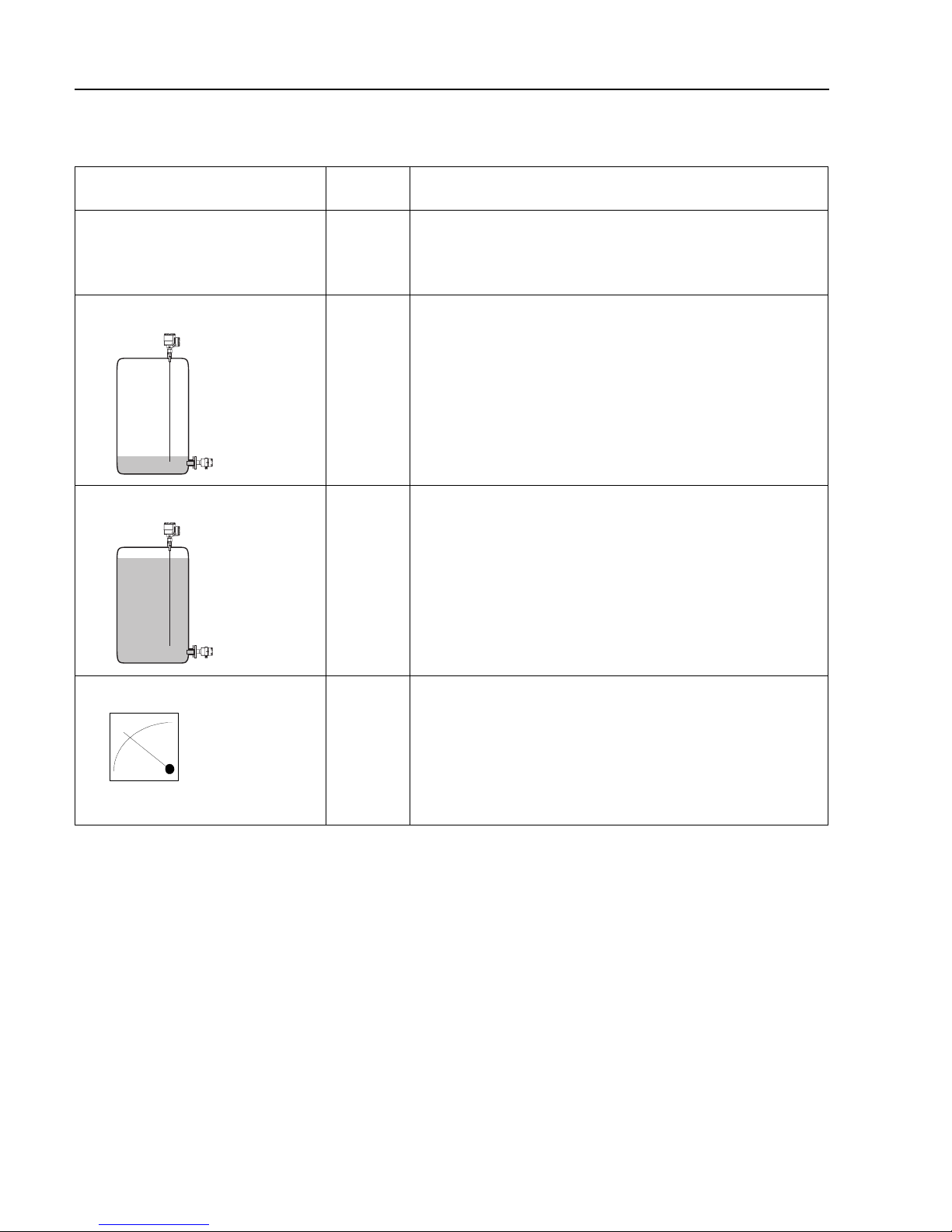
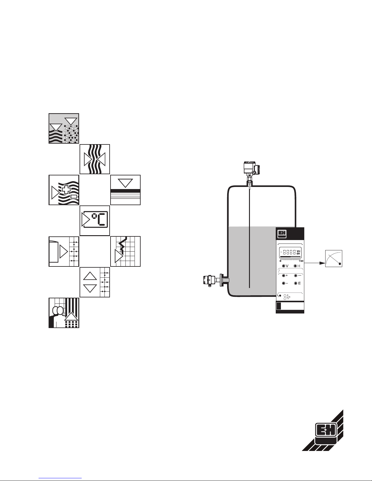
Level Measurement at a Glance
*Can be performed in reverse order
Function Matrix Action
1 Reset transmitter V9H5 ●Enter 671: »+« and »-« keys, ⇒ changes digit
Press »E« to register entry
- Omit if commissioned as in Section 4.1
2 »Empty« calibration* V0H1 ●Fill vessel 0…40% full (probe covered)
Enter level in %, m, ft, etc.
Press »E« to register entry
3 »Full« calibration* V0H2 ●Fill vessel 60…100% full
Enter level in %, m, ft, etc.
Press »E« to register entry
4 0/4 mA signal V0H3
V0H5
V0H6
●Enter 0 for 0…20 mA signal, 1 for 4…20 mA signal
Press »E« to register entry
●Enter level for 0/4 mA signal (if not 0)
Press »E« to register entry
●Enter level for 20 mA signal (if not 100)
Press »E« to register entry
Silometer FMX 570 Measurement at a Glance
Page 3
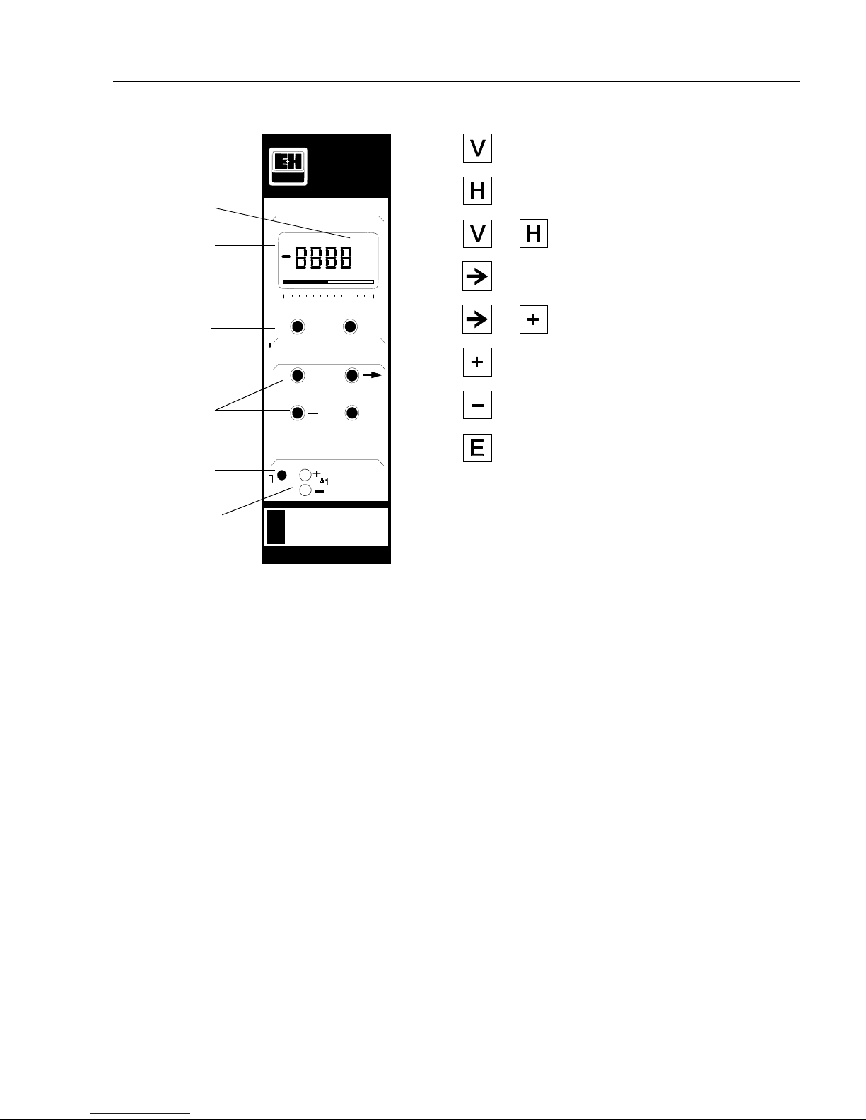
Silometer FMX 570
Selects vertical matrix position
Selects horizontal matrix position
Select position V0H0
Selects next digit
Move decimal point
Increases value of digit
Decreases value of digit
Registers entry
0 100
VH
00
VH
+
E
FMX 570
m
Measured
value
Bar chart
Matrix
selection
Parameter entry
Alarm relay
lit: fault
Matrix position
Test sockets for
0/4…20 mA output
+
+
See also »Controls«, Chapter 3
Measurement at a Glance Silometer FMX 570
1
Page 4

Table of Contents
Measurement at a Glance
Notes on Safety . . . . . . . . . . . . 3
1 Introduction . . . . . . . . . . . . . 5
1.1 Application . . . . . . . . . . . . . . . 6
1.2 Measuring principle . . . . . . . . . . . 7
2 Installation . . . . . . . . . . . . . . 8
2.1 Probes and sensors . . . . . . . . . . . 8
2.2 Silometer installation . . . . . . . . . . . 9
2.3 Transmitter wiring . . . . . . . . . . . . 11
2.4 Sensor connection . . . . . . . . . . . . 13
2.5 Technical data: Silometer FMX 570 transmitter . 14
3 Controls . . . . . . . . . . . . . . . 15
3.1 Commutec operating matrix . . . . . . . . 15
3.2 Configuration and display . . . . . . . . . 16
4 Calibration and Operation . . . . . . . 17
4.1 Commissioning . . . . . . . . . . . . . 17
4.2 Calibration for level measurement . . . . . . 18
4.3 Calibration for linear volume or weight
measurement . . . . . . . . . . . . . . 19
4.4 »Dry calibration« for open vessels . . . . . 20
4.5 Level offset value . . . . . . . . . . . . 22
4.6 Measured value display . . . . . . . . . 23
4.7 Locking the parameter matrix . . . . . . . 23
5 Linearization . . . . . . . . . . . . . 24
5.1 Linearization for a horizontal cylindrical tank . 25
5.2 Linearization for a tank with conical outlet . . 26
5.3 Other modes . . . . . . . . . . . . . . 29
6 Analogue Outputs . . . . . . . . . . 30
6.1 Analogue output settings . . . . . . . . . 31
7 Trouble-Shooting . . . . . . . . . . . 33
7.1 Trouble-shooting tables . . . . . . . . . 33
7.2 Simulated operating mode . . . . . . . . 35
7.3 Exchanging transmitters, probes and electronic
inserts . . . . . . . . . . . . . . . . 36
7.4 Repairs . . . . . . . . . . . . . . . . 37
8 Quick programming guide . . . . . . . 38
8.1 Level measurement . . . . . . . . . . . 38
8.2 Continuous volume measurement (linearization) 39
Index . . . . . . . . . . . . . . . . 40
Operating matrix
Silometer FMX 570 Table of Contents
2
Page 5
Notes on Safety
The Silometer FMX 570 is a level measurement transmitter which can be used with a
variety of probes and sensors. It must be installed by qualified personnel according to
the instructions in this manual.
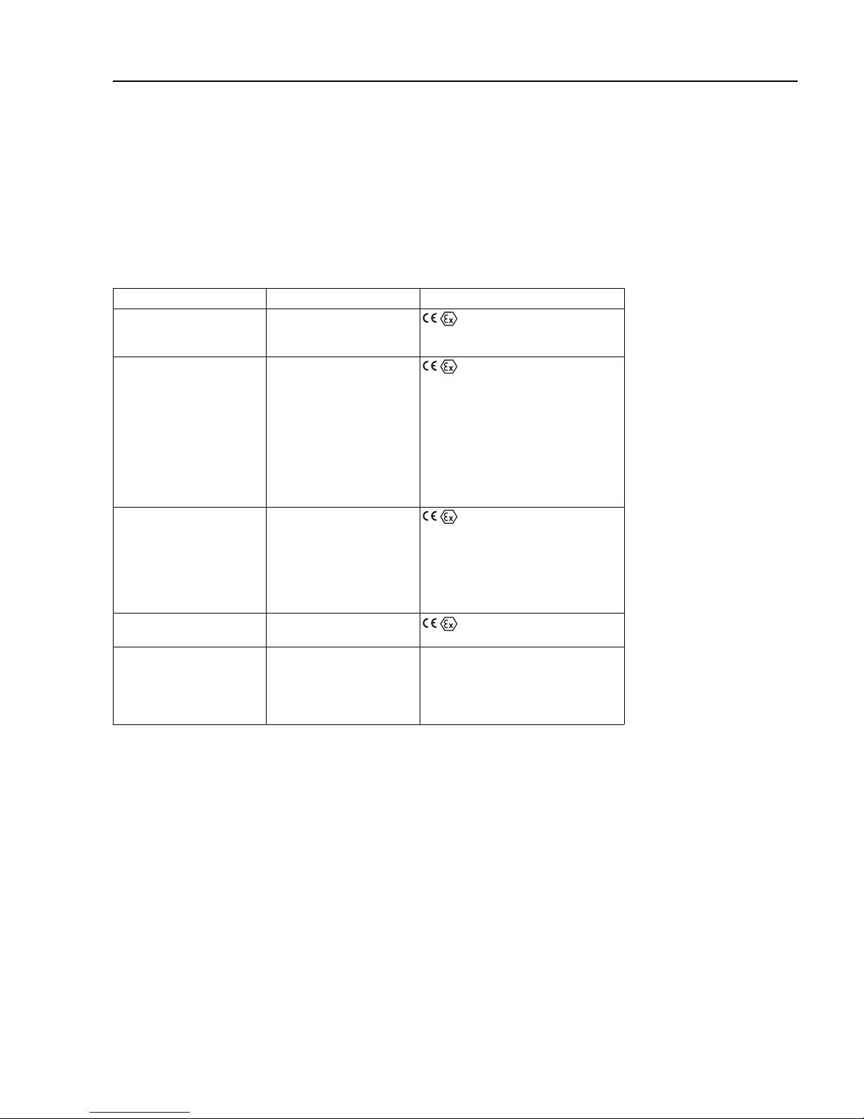
CertificatesThe Silometer FMX 570 transmitter is available with certificate. The Table below indicates
the combinations available and conditions for installation. Full details can be taken from
the certificates. Please note that where quoted technical data differs from that listed in
Section 2.5, that in the certificate applies.
Certificate Instruments Notes
TÜV 00 ATEX 1640 Silometer FMC 671 Z/676 Z II (1) GD,
[EEx ia] IIC/IIB,
install outside Ex-area
PTB 98 ATEX 2215 X DC 12 TE, DC .. TE .,
DC .. E ., DC ..
Capacitance probes
11500 Z(M), 11961 (Z),
21561 (Z)
with electronic insert
EC 16/17/27/37/47 Z,
FEC 12,
HTC 16/17/27 Z, HTC 10 E,
HMC 37/47 Z
II 1/2 G, II 2 G,
EEx ia IIC/IIB T6
PTB 98 ATEX 2215 X DC 12 TE, DC .. TE .,
DC .. E ., DC ..
Capacitance probes
11500 Z(M), 11961 Z,
21561 Z
with electronic insert
EC 17/37/47 Z, FEC 12
II 1 G,
EEx ia IIC/IIB T6
PTB 98 ATEX 2094 DB 50, DB 50 L,
DB 51, DB 52, DB 53
II 1/2 G, II 2 G,
EEx ia IIC T4…T6
DIBt No. Z-65.11-29 Silometer FMX 570,
DB 50…52
with electronic insert
FEB 17 / FEB (17) P
Continuous level measurement
for overspill protection in stationary
vessels
(for storage of non-combustible,
water-polluting liquids)
Silometer FMX 570 Notes on Safety
3
Page 6

Safety conventions
In order to highlight safety-relevant or alternate operation procedures in the manual the
following conventions have been used, each indicated by a corresponding icon in the
margin.
Note!
• A note highlights actions or procedures which, if not performed correctly, may
indirectly affect operation or may lead to an instrument response which is not
planned.
Caution!
• Caution indicates actions or procedures which, if not performed correctly, may lead
to personal injury or incorrect functioning of the instrument.
Warning!
• A warning indicates actions or procedures which, if not performed correctly, will
lead to personal injury, a safety hazard or destruction of the instrument.
Notes on Safety Silometer FMX 570
4
Page 7

1 Introduction
Quick Operating GuidesThe front cover contains short instructions for continuous level measurement with the
default parameters.
In this manualUsers unfamiliar with the Silometer FMX 570 must read the operating instructions, which
are structured as follows:
• Chapter 1: Introduction;
contains general information including application, measurement
principle and functional description.
• Chapter 2: Installation;
contains hardware configuration, installation instructions.
connection diagrams and technical data for the plug-in card.
• Chapter 3: Controls;
describes the front panel keys and operating matrix.
• Chapter 4: Calibration and Operation;
tells you how to commission the Silometer for level measurement.
• Chapter 5: Linearization;
tells you how to calibrate the Silometer to measure volume in a
horizontal cylindrical tank or a tank with a conical outlet.
• Chapter 6: Analogue Outputs;
describes in detail the setting of the 0/4…20 mA signal line.
• Chapter 7: Trouble-Shooting;
contains a description of the self-checking system with error
messages, the simulation feature as well as instructions for
configuration on replacement of the transmitter, probe or electronic
insert.
• Chapter 8: Short Operating Guide
contains a flowcharts for level and volume measurements
• Chapter 9: Index;
lists key words to help you find information quickly.
• Chapter 10: Operating Matrix
contains the operating matrix, the default parameters and a table to
enter your operating parameters,
Further documentationInstallation of the probes, electronic inserts and accessories are described in the
documentation accompanying these articles - see text for references. When installing
probes in explosion hazardous areas the instructions included in the accompanying
probe certification must also be observed.
Silometer FMX 570 Chapter 1: Introduction
5
Page 8
1.1 Application
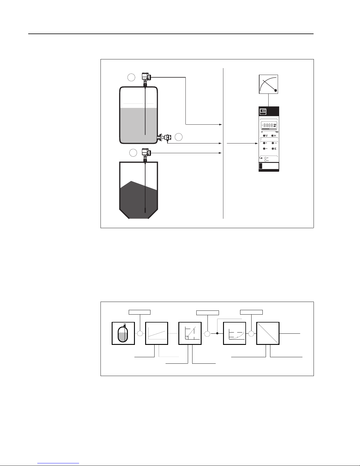
The Silometer FMX 570 is designed for level measurement with a capacitance or
hydrostatic pressure probe in safe or explosion hazardous areas. It possesses an
intrinsically-safe sensor circuit conforming to EEx ia IIC and IIB. A list of certificated
combinations is to be found in »Notes on Safety« preceding this chapter. A working
system for level measurement comprises:
• Silometer FMX 570 transmitter,
• Capacitance, Multicap or Deltapilot S probe
• Electronic insert
Silometer function The capacitance or pressure measured by the sensor is converted into a frequency
signal by the electronic insert located in its head. The Silometer FMX 570 supplies the
power and receives a level-proportional frequency signal over a two-core cable. The
signal is then processed to provide a level or volume measurement.
Fail-safe operation If a fault condition is detected, e.g. a break in sensor - transmitter cable, the analogue
signal switches to -10 % or +110 % level or holds the last measured value. In addition,
the alarm relay de-energises.
2
1
1
FMX 570
mA1
0/4...20 mA,
0/2...10V
output
Silometer
FMX 570
transmitter
Liquids
Bulk solids
Channel 1
Ex non-Ex
or
or
BA119Y01
Fig. 1.1:
Standard application showing
Silometer FMX 570 controlling
level measurement
➀
Capacitance probe
➁
Deltapilot
frequency
analog
digital
current
voltage
sens. [Hz/pF]offset [Hz]
offset [pF] sens. [pF/cm]
range upper limit
V2
range lower limit
V1
frequency
electronicinsert
electronicinsert
capacit./
pressure
volume
V2
V1
level
volume
H2
H1
level
cap./press.
level
zero point shift
BA119E08
Fig. 1.2
Signal processing in the
Silometer FMX 570
Chapter 1: Introduction Silometer FMX 570
6
Page 9
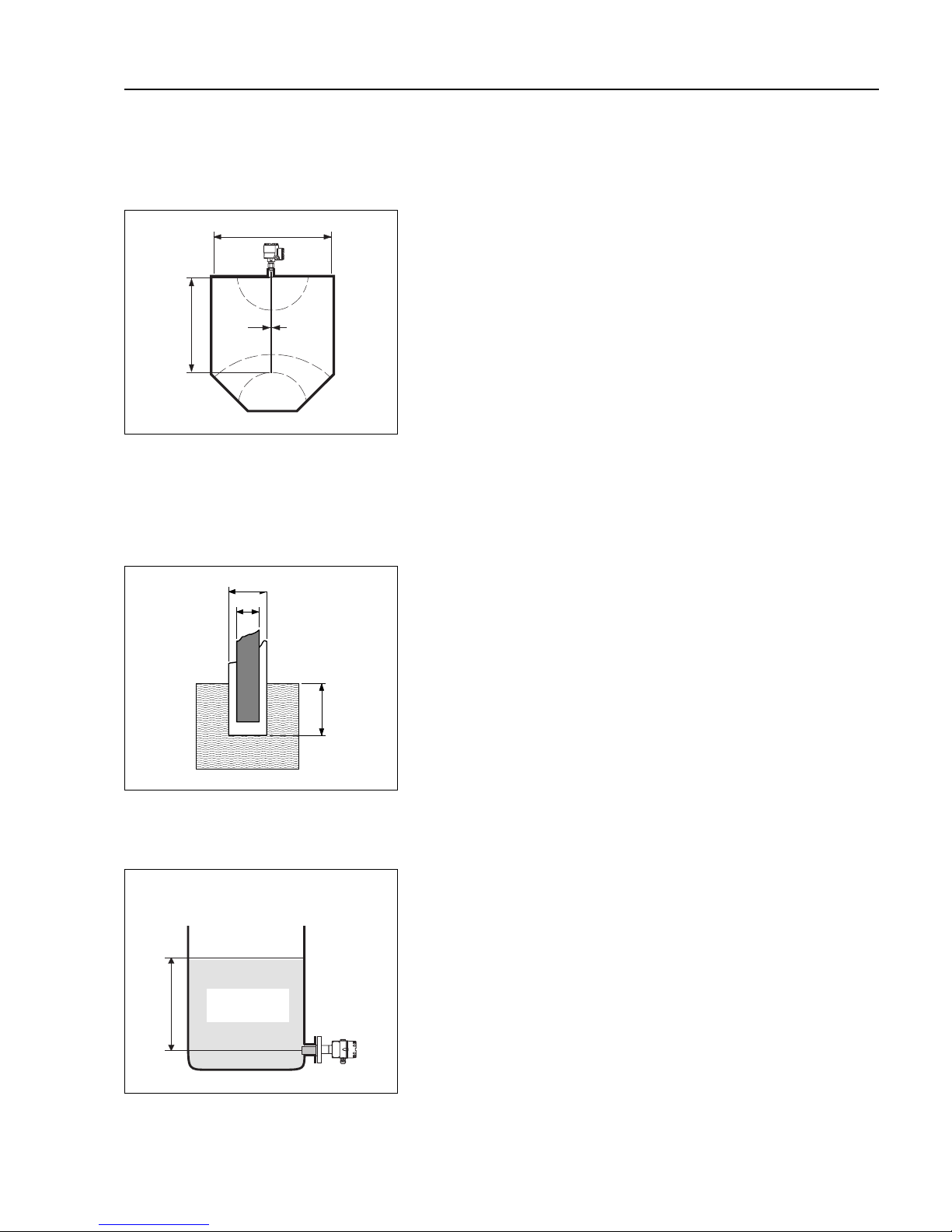
1.2 Measuring principle
The Silometer FMX 570 measures level on the basis of the capacitance and hydrostatic
measurement principles. In both cases the measured value is processed by the
electronic insert and passed on as a frequency signal.
The probe and vessel form the two plates
of a capacitor, the total capacitance of
which can then be calculated from the
formula:
C
tot
=C
1
+ 2πε0ε
r
x L pF (1)
--------------------------------
ln (D/d)
whereby
C
tot
= total capacitance
C
1
= capacitance or feed through
ε
0
= dielectric constant of air
ε
r
= rel. dielectric constant of product
D= diameter of vessel
d= diameter of probe
L= length of probe immersed in
product in meters
If the product conducts, the capacitance is
determined by the thickness and
properties of the insulating material
surrounding the probe. Equation (1)
applies, whereby the variable D is now the
diameter of the probe with insulation. In this
case the capacitance varies by approx.
300 pF/m.
Measurement is independent of dielectric
constant and not affected by changes in
this variable.
In an open vessel, the level is derived from
the hydrostatic pressure exerted by a
column of liquid on a probe placed at its
foot. The pressure exerted is:
p
1
= ρ x g x h (2)
whereby
p
1
= hydrostatic pressure
ρ = density of the liquid
g = acceleration due to gravity
h = height of the liquid column.
Assuming a constant density, the level of
the liquid can be calculated from the
pressure measured by the Deltapilot.
BA119Y05
d
L
D
C
1
Fig. 1.3
Capacitance measurement principle
BA119E06
d
Conducting
product
L
D
Fig. 1.4
Measurement in conducting media
BA119Y07
p1 = ρ x g x h
h
atmospheric
pressure
p
1
Fig. 1.5
Hydrostatic measurement principle
Capacitance
measurement
Hydrostatic
measurement
Measurement in
conducting media
Silometer FMX 570 Chapter 1: Introduction
7
Page 10
2 Installation
This Chapter describes:
• The probes for use with the Silometer FMX 570
• Silometer installation in a rack or Monorack housing
• Transmitter wiring
• Sensor connection.
• Technical data.
Warning!
• The Silometer FMX 570 transmitter must be installed outside explosion hazardous
areas.
2.1 Probes and sensors
Table 2.1 lists the probes most frequently used with the Silometer FMX 570 transmitter.
In addition to those listed, all probes which can be used with an EC 37 Z or EC 47 Z
electronic insert can be connected to the transmitter. Installation hints can be taken from
the appropriate Technical Information Sheet.
Sensor constants Deltapilot S sensors and EC 37 Z/47 Z inserts for capacitance probes are supplied with
the sensor constants zero frequency »fo« and sensitivity »∆f« or »S«. For Deltapilot S
sensors the constants are printed on a label stuck inside the sensor head, for inserts
they are printed on the name plate, see Fig. 7.1, Section 7.3.
Note these constants and enter them into fields V3H5 and V3H6 during commissioning,
Section 4.1. This dispenses with the need for a recalibration of the transmitter on
replacement of the sensor or insert.
Principle Probe TI sheet Insert
Capacitance,
Multicap
11 500 Z TI 161F
Multicap DC 11 TI 169F
Multicap DC 16 TI 096F
Multicap DC 21 TI 208F
Multicap DC 26 TI 209F
Multicap TA TI 239F
Multicap TE TI 240F
Multicap E TI 242F
Multicap A TI 243F
EC 37 Z
EC 47 Z
FEC 12
Hydrostatic pressure Deltapilot S TI 031F
DB 50...53 TI 257P
FEB 17 (P)
Table 2.1:
Selection of probes suitable for
use with the Silometer FMX 570
Cell
type
Electronic insert FEB 17/FEB 17 P
Range f
0
∆
fRange f
0
∆
f
0.1 bar BA 0…100 mbar 200 10 DA -100…100 mbar 200 5
0.4 bar BB 0…400 mbar 200 2.5 DB -400…400 mbar 200 1.25
1.2 bar BC 0…1200 mbar 200 0.833 DC -900…1200 mbar 200 0.476
4.0 bar BD 0…4000 mbar 200 0.25 DD -900…4000 mbar 200 0.204
Table 2.2:
Measuring ranges and sensor
constants of the
Deltapilot S DB 5x
Silometer FMX 570 Chapter 2: Installation
8
Page 11
2.2 Silometer installation
There are three possibilities for installing Silometer transmitters:
• Standard 19" rack with space for 12 7HP cards,
• Field housing with space for up to 6 7HP cards,
• Monorack housings for single transmitters.
Rack installationA Racksyst system can be ordered fully wired, in which case the sensors and the external
power supply only need to be wired. Planning hints can be found in Publication
SD 041/00/e, »Racksyst Assembly Racks« .
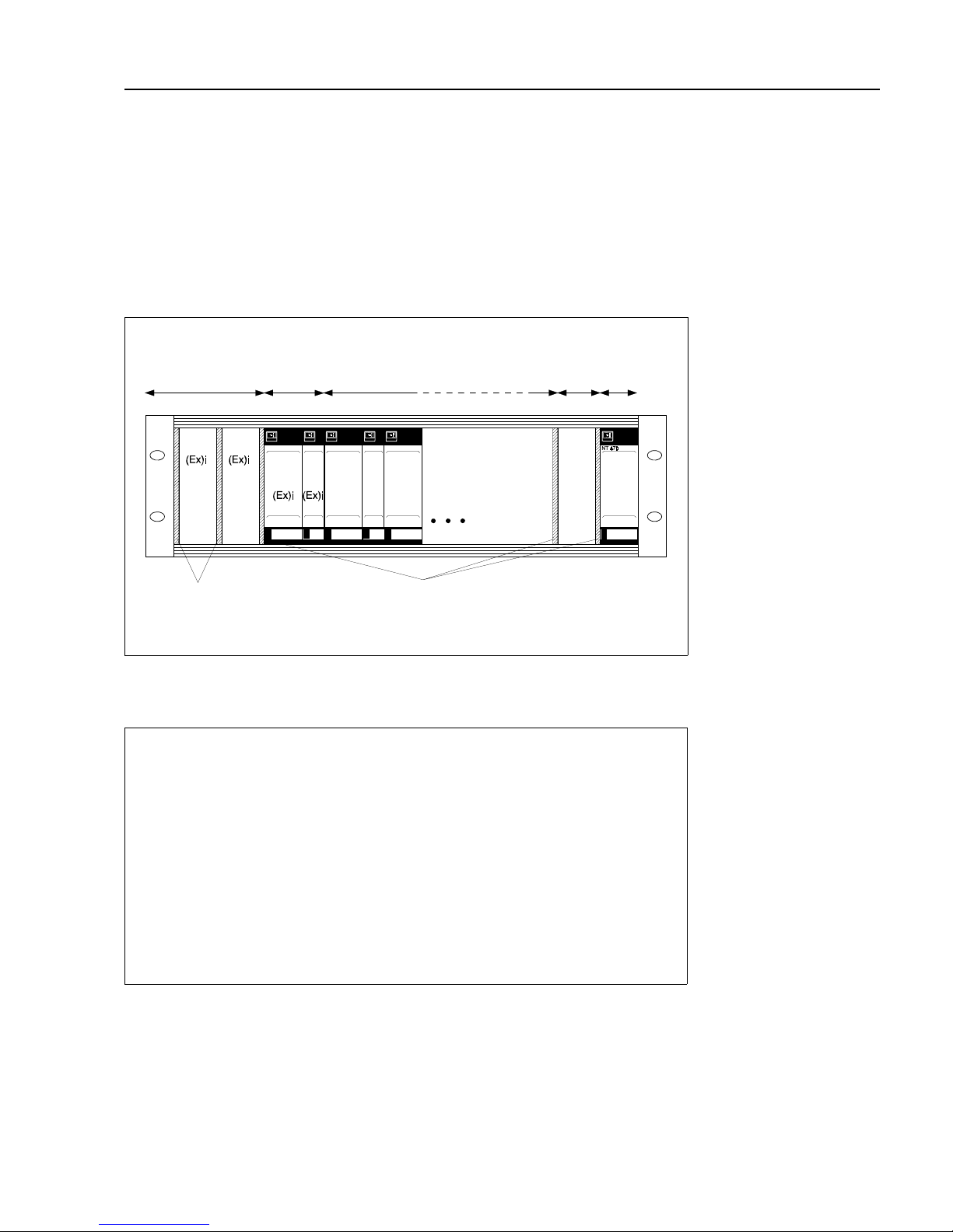
For non-Racksyst installations and for installations including non-Racksyst cards, fill the
rack as follows (see also Fig. 2.1):
Rack arrangement
Step Procedure
1 Allocate the power supply (NT 470) at the rightmost position.
- If two NT 470s are used, install a 2 HP dummy panel between them.
2 Install non-intrinsically safe transmitters next to the power supply.
- Install a 2 HP dummy panel between all foreign transmitters and between
Racksyst cards and foreign transmitters
3 Install intrinsically safe transmitters to the left of the rack.
- Install foreign cards first.
- Install dummy panels between all foreign transmitters and between Racksyst
cards and foreign transmitters in accordance with the instructions on the
Ex-Certificate.
- No spacer is required between Racksyst cards.
Racksyst field housingInstructions for installing Commutec transmitters in the Racksyst field housing with half
19" rack are to be found in Publication PI 003.
• Check that the field housing is not installed in direct sunlight.
- If appropriate fit a protective sun cover.
• The maximum permissible ambient temperature for the field housing varies
between +50…+60 °C according to the power consumption of the cards
(0…20 W)
BA119E09
Non-E+H
(Ex)i devices
E+H (Ex)i
devices
E+H devices Non-E+H
devices
NT power
supply
Spacing between
non-E+H (Ex)i devices
as per certificate
2 HP dummy panel between
E+H and non-E+H devices
Fig. 2.1:
Recommended arrangement for
Racksyst rack assemblies
Chapter 2: Installation Silometer FMX 570
9
Page 12
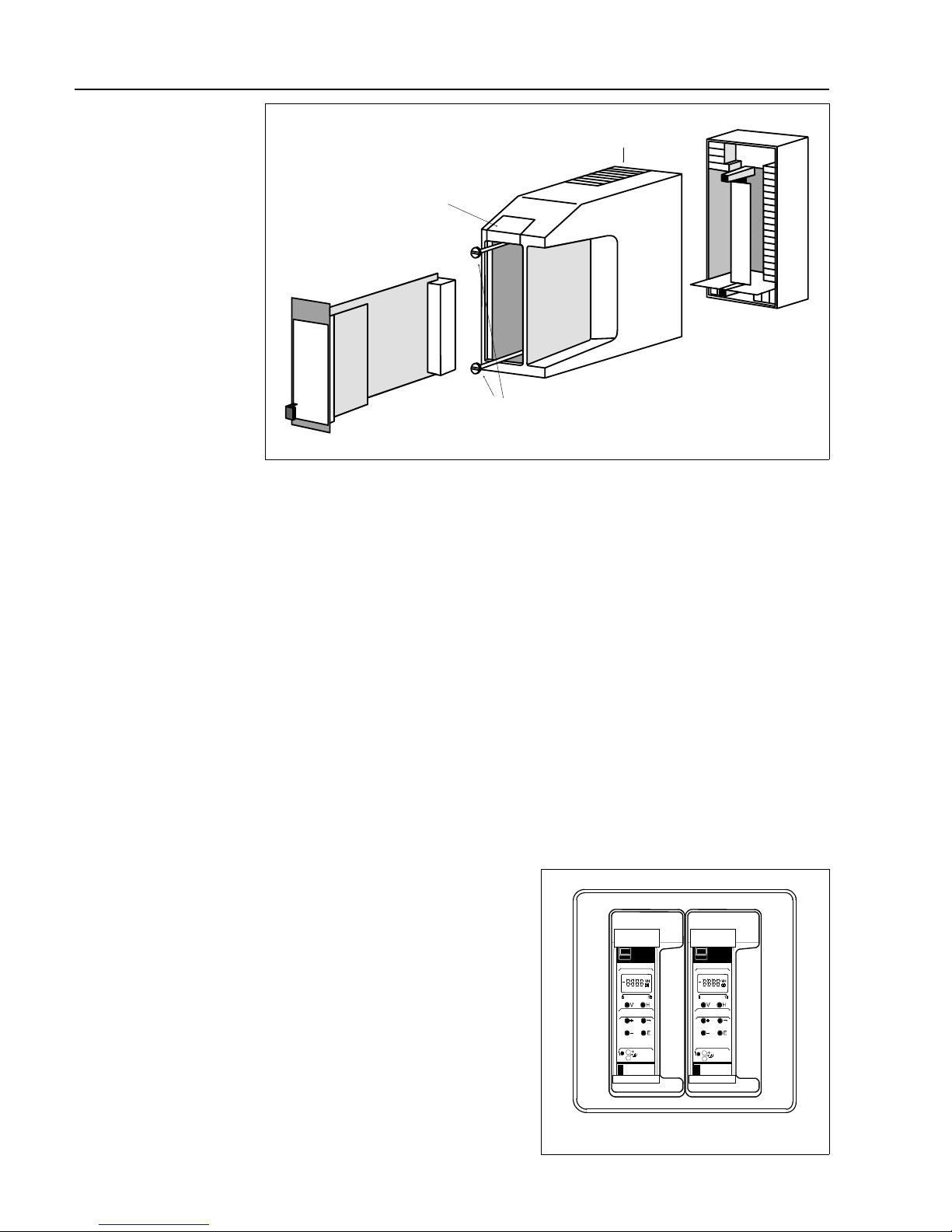
Monorack housing The Silometer FMX 570 transmitter and Monorack housing are supplied separately. The
system must be assembled as shown in Fig. 2.2 before use.
• The Monorack is prepared for wall-mounting, degree of protection IP 40.
• The site must be chosen such that the operating temperature of
-20°C…+60°C for one Monorack and -20°C…+50°C for Monorack banks is
not exceeded.
Full details of the Monorack installation procedure can be taken from the manual supplied
with it.
Monorack protective
housing
If the Silometer FMX 570 transmitter and Monorack housing are to be mounted at an
exposed site, then it is recommended that they be installed in the protective housing,
degree of protection IP 55, which is available as an accessory.
• The protective housing accomodates two Silometer FMX 570 transmitters.
• The permissible ambient temperature is -20°C…+50°C for one Monorack and
-20°C…+40°C for two.
Dimensions and instructions for installation are to be found in the Technical Information
sheet TI 099/00/e.
BA119E10
Plug-in card
Monorack
housing
Monorack base
(terminal block)
Retaining
screws
Retaining
flap
Fig. 2.2:
Assembly and disassembly of
the Monorack housing
Power
pack
Fig. 2.3:
Monorack protective housing
BA119E60
Silometer FMX 570 Chapter 2: Installation
10
Page 13
2.3 Transmitter wiring
Warning!
• Make electrical connections with the power supply switched off!
• When wiring up probes and sensors in explosion hazardous areas, observe the
instructions on the certificate and other appropriate regulations.
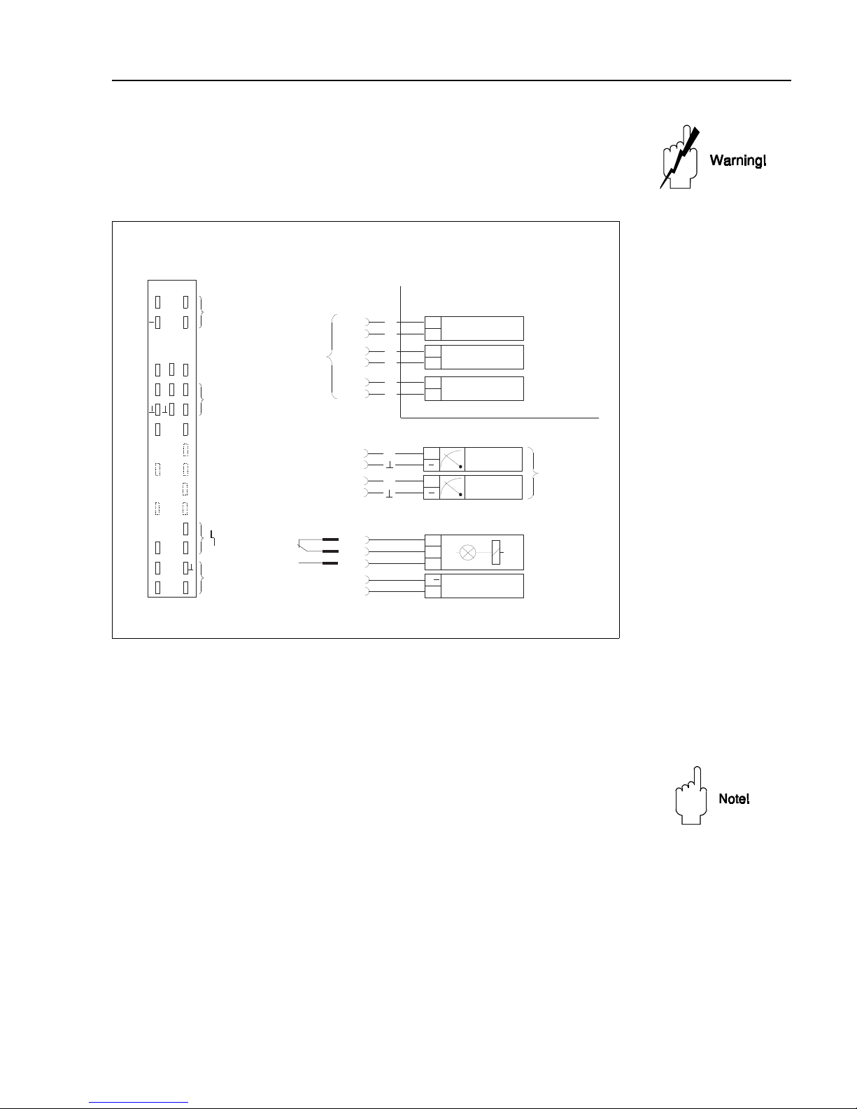
Rack wiringFig. 2.4 is a pin assignment diagram for the Silometer FMX 570.
• Terminals z 30, b 14 and d 14 are connected internally
• Inputs d2, d4 are electrically isolated from the circuit and each other.
• The circuit zero of the unit ( ⊥ ) is connected to the negative terminal of the
supply voltage.
Note!
• Two indexing pins, at positions 2 and 9 in the rack connector ensure that Silometer
FMX 570 transmitters only can be inserted at these points. The pins must be
inserted if the rack is not custom built by Endress+Hauser.
Analogue outputsThe negative terminal of the current output, of the voltage output and of the supply voltage
are connected to the circuit zero of the Silometer FMX 570 module.
• Any number of measurement and control units can be connected in parallel to
the voltage output, provided that all potentials are related to negative terminal
of the 24 V supply (R
L
≥ 10 kOhm).
- There is no limit to the number of floating devices, apart from that imposed
by considerations of maximum or minimum load.
• Only one non-floating device can be connected to each of the current
outputs.
d b z
+
2
4
6
8
2
1
+
-
EC 47 Z
d2
d4
3
2
+
-
FEB 17 (P)
d2
d4
2
1
+
-
EC 37 Z
d2
d4
L
L+
20 V...30 V
z30
d32
+
+
d12
d14
0/4...20 mA
+
+
b12
b14
0/2...10 V
r
z26
d28
z28
u
a
10
12 + +
14
16
32 L+
18
20
22
24
26 r
28 u a
30 -L
Analogue
outputs
Alarm relay
Power supply
Level,
volume
BA119Y11
Alarm relay
FMX 570
Non-Ex- area
Input
DC supply
Deltapilot S
Ex-area
Current
Voltage
Capacitance/
Multicap probe
Capacitance/
Multicap probe
Input
Fig. 2.4:
Pin assignment diagram for
Silometer FMX 570
Chapter 2: Installation Silometer FMX 570
11
Page 14
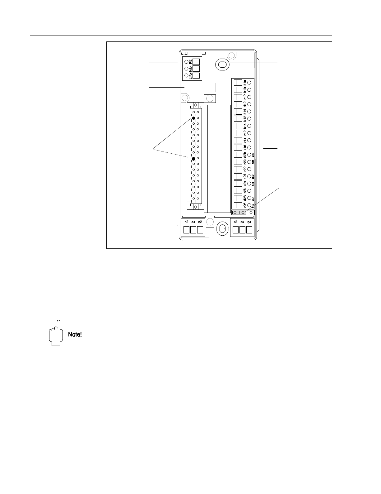
Monorack wiring Fig. 2.5 shows the layout in the base of the Monorack II housing, the pin assignments
correspond to those in Fig. 2.4. When connecting together several Monoracks, follow
the instructions supplied with the housing.
• Set the jumper to position "Racksyst I"
• Insert the coding pins supplied at positions 2 and 9 in the female connector
at the base of the housing.
• The pin assignments printed in black are valid for the Silometer FMX 570.
Note!
If you are installing the Silometer FMX in a Monorack I housing, please note that there is
no jumper switch. In addition, for the 24 VDC version, the dummy card in the power
control slot must be replaced by the 24 V card supplied.
PC board
slot
BA119E14
Power
Outputs
see Fig. 2.4
Input, d2, d4
Insert coding pins
for Z-version at
Positions
2 and 9
Hole for mounting
screw
Hole for mounting
screw
Jumper positioned
for Racksyst I card
Fig. 2.5:
Layout of Monorack terminal
blocks
Silometer FMX 570 Chapter 2: Installation
12
Page 15
2.4 Sensor connection
The Silometer FMX 570 can be operated with a variety of sensor types, each requiring
a different electronic insert, e.g.:
• EC 37 Z or EC 47 Z for capacitance and Multicap probes
• EB 17 Z or EB 27 Z for Deltapilots
Sensor cableUse commercial 2-core installation cable, max. line resistance 25 Ω/core, for the sensor/
transmitter cable. If electromagnetic interference is to be expected, we recommend
• that the PFM negative line be grounded at the sensor (check Ex-regulations)
• in case of heavy interference, that shielded cable be used, grounded at both
ends.
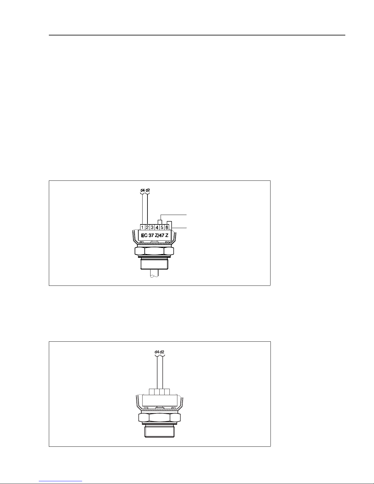
EC 37 Z and EC 47 ZThe electronic inserts EC 37 Z and EC 47 Z have two measuring ranges which can be
selected by inserting a bridge between terminals 4 and 5 of the insert, see Fig 2.6. Full
instructions on the selection of the insert are to be found in Publication E 07.80.06/1c.
• Note the zero frequency f
o
____ and sensitivity S_____on the insert.
FEB 17 (P)The FEB 17 (P) electronic insert can be used with Deltapilot S sensors to measure level
and volume in open vessels.
• Note the zero frequency f
o
_____ and sensitivity ∆f _____ of the probe
(see Table 2.2 on page 8)
BA119E15
Insert bridge for
Range II (standard)
Remove for Range I
Ground
connection
FMX 570 input
Fig. 2.6:
Connection diagram for
electronic inserts
EC 37 Z/EC 47 Z
FEB 17/FEB 17 P
1234
BA119Y18
FMX 570 input
Fig. 2.7:
Connection diagram for
electronic insert
FEB 17 (P)
Chapter 2: Installation Silometer FMX 570
13
Page 16

2.5 Technical data: Silometer FMX 570 transmitter
Construction
• Design: 19", 7 HP, plug-in card
• Front panel: black synthetic with blue field inlay, grip and markings,
Protection: IP 20 (DIN 40050)
• Dimensions: see diagram
• Weight: approx. 0.3 kg/11 oz
• Operating temperature: -0 °C...+70 °C/+32 °F..158 °F
Storage temperature: -20 °C...+85 °C/-4 °F...185 °F
Electrical connection
• Multipoint plug: conforming to DIN 41612, Part 3, Type F (28-pole)
Coding pins in positions 2 and 9
• Power supply: 24 V DC (+6 V…-4 V); residual ripple 2 V, within tolerance
• Supply current: approx. 90 mA, max. 125 mA
• Signal inputs: Electrically isolated from the rest of the circuitry.
Protection [EEx ia] IIC or IIB
• Probes: Capitance probes, impedance probes
with EC 37 Z or EC 47 Z electronic insert
Deltapilot S with electronic insert FEB 17 / FEB 17 P
• Electromagnetic Interference Emission to EN 61326, Electrical Equipment Class A
compatibility: Interference Immunity to EN 61326
Outputs
• Analogue output: 0...20 mA/4...20 mA selectable, R
L
max. 500 Ω
0...10 V/2...10 V selectable, R
L
min. 10 k Ω
• Alarm relay relay with a potential-free change-over contact
Max. switching capacity:
2.5 A, 250 VAC, 300 VA at cos ϕ > 0.7 or
100 VDC, 90 W
Certificates
• Silometer FMX 570 Intrinsically safe circuit to [EEx ia] IIC and IIB
(PTB certification in preparation)
see also »Safety Notes«.
BA119E22
Fig. 2.8
Silometer FMX 570 plug-in card
Silometer FMX 570 Chapter 2: Installation
14
Page 17

3 Controls
This Chapter describes how the Silometer FMX 570 transmitters are operated. It is
divided into the following sections:
• Commutec operating matrix
• Configuration and display: Silometer FMX 570
3.1 Commutec operating matrix
All functions, including the analogue outputs and relay switch points are configured via
the operating matrix, see Fig. 3.1:
• Each field in the matrix is accessed by a vertical (V) and horizontal (H)
position which can be entered at the front panel of the FMX 570 with the
V and H keys
• The parameters are entered with the plus, minus, arrow and enter keys.
Parameter at current matrix
position
Pressed together
Move to V0H0
Move H0 …H9, H0
Move V0…V9, V0
BA119E25
Current matrix position
Fig. 3.1:
Silometer FMX 570 display
Parameter matrix operation with
function of V and H keys.
The complete matrix has 10 x 10
fields, although not all are used
Silometer FMX 570 Chapter 3: Controls
15
Page 18

3.2 Configuration and display
Fig. 3.1 shows the LC-display with matrix of the Silometer FMX 570, Fig. 3.2 its front panel.
Table 3.1 below describes the function of the operating keys.
• Changes are not possible if the matrix has been locked (Section 4.7).
• Non-flashing parameters are either read-only indications or locked entry fields.
0 100
VH
00
VH
+
E
FMX 570
m
Measured value display with
10-step bar chart showing
percentage 0/4 …20 mA signal
Parameter entry keys
Alarm relay LED
•
Lights on fault condition,
relay de-energises
•
Flashes on warning,
relay remains energised
Matrix selection keys
Matrix position indicator
BA119E23
Test sockets for
0/4…20 mA current output
Fig. 3.2:
Front panel of the
Silometer FMX 570 transmitter
Keys Function
Matrix selectio n
•
Press V to select the vertical position.
•
Press H to select the horizontal position
•
Press simultaneously to select the measured value field, V0H0
Parameter entry
•
Select the digit to be changed.
The digit at the extreme left is selected and flashes.
•
Move to the next digit by pressing »⇒« again. When the last digit
is reached »⇒« selects the leftmost digit again.
•
To change the position of the
decimal point
, press down both
»⇒« and »+«. The decimal point moves 1 space to the right.
•
Increases the value of the flashing digit
•
Decreases the value of the flashing digit
•
To enter a
negative number
decrease the leftmost digit until a
minus sign appears in front of it
•
Press »E« to register entry.
•
Unregistered entries remain ineffective and the instrument will
operate with the old value.
+
+
Table 3.1:
Silometer FMX 570
Parameter entry and display keys
Chapter 3: Controls Silometer FMX 570
16
Page 19

4 Calibration and Operation
This chapter is concerned with the basic settings of the Silometer FMX 570 which allow
it to operate for continuous level measurement. The principle sections describe:
• Commissioning
• Calibration for level measurement
• Calibration for linear volume or weight measurement
• Dry calibration for Deltapilot probes
• Level offset
• Display of measured values
• Locking the parameter matrix.
The linearization for volume or weight measurements is described in Chapter 5, the
setting of the analogue outputs in Chapter 6 and the controls in Chapter 3.
Note your settings!When configuring, note your parameters in the Table in the rear cover.
• If the transmitter is ever replaced, these parameters can be entered at the
front panel. The transmitter will then measure correctly without the need for
another calibration.
4.1 Commissioning
If programming the module for the first time, reset the module to the factory based
parameters, see Table in back cover. Then enter the probe constants fo and S (∆f). This
ensures that the EC 37 Z/EC 47 Z electronic insert or Deltapilot can be replaced without
the need for recalibration, see Section 7.3.
Step Matrix Entry Significance
1 V9H5 e.g. 672 Enter any number 670…679 to reset transmitter
2 - »E« Register change
3 V3H5 e.g. 475.3 Enter zero frequency f
o
(offset) of electronic insert or sensor
4 - »E« Register change
5 V3H6 e.g. 0.652 Enter sensitivity, S or ∆f, of electronic insert or sensor
6 - »E« Register change
Operating modeThe operating mode is set at V8H0. Since the default value corresponds to level
measurement, this step can be omitted if the transmitter has been reset.
For a recalibration without reset check that mode 1, is on display:
• 1 = continuous level measurement, Sections 4.2, 4.3, 4.4.
• 6 = simulation, see Chapter 7, Section 7.2.
Step Matrix Entry Significance
1 V8H0 e.g. 1 Mode 1, continuous level measurement
2 - »E« Register entry
Chapter 4: Calibration and Operation Silometer FMX 570
17
Page 20

4.2 Calibration for level measurement
This calibration requires the determination of two parameters,
• an »empty« level at V0H1,
• a »full« level at V0H2.
After calibration If the level is entered in %, after the calibration:
• % level is displayed at V0H0
• the 0/4…20 mA signal range corresponds to 0…100% level
• the parameters »offset« and »sensitivity« are calculated and stored at
V3H1/V3H2.
If the level is entered in m, ft. etc. the analogue outputs must be set in the same units,
see Chapter 6.
Procedure
Step Matrix Entry Significance
1 V0H1 e.g. 10% Fill the vessel until the probe is covered (ca. 0…40%) and
enter the level you wish to have displayed.
2 - »E« Register entry
3 V0H2 e.g. 95% Fill the vessel as far as possible (ca. 60…100%) and
enter the level you wish to have displayed.
4 - »E« Register entry
5 V0H0 The measured value is shown in the units selected.
Note!
• The calibration can be performed in reverse order
• For bulk solids, the probe measures the depth of emersion in the product only.
Account for any filling mound or outflow depression by the entered levels.
• For the Deltapilot S (liquids only), a »dry calibration« can be made see Section 4.4.
• If appropriate, a linearization can now be carried out, see Chapter 5.
»Full« V0H2
e.g. 95% or 5 m
BA119Y27
Capacitance probe
Capacitance probe
»Empty«, V0H1
e.g. 10% or 0.5 m
Fig. 4.1:
Parameters required for
calibration of the Silometer
FMX 570 for level measurement
shown for bulk solid
measurement.
Any filling mound or outflow
depression can be accounted for
by the parameters entered.
Silometer FMX 570 Chapter 4: Calibration and Operation
18
Page 21

4.3 Calibration for linear volume or weight measurement
The Silometer FMX 570 can also be calibrated in volume or weight units, e.g. in litres,
hectolitres, gallons, %vol, tonnes or kg. After calibration volume (or weight) is displayed
at V0H0. The analogue output must be set in the same units, as described in Chapter 6.
If the level/volume relationship is not linear, i.e. the tank is a horizontal cylinder or has a
conical outlet, the volume calibration is performed as part of the linearization procedure.
In this case, before proceding further, turn to Chapter 5, Section 5.1 or 5.2 to determine
the correct order of parameter entry.
Procedure
Step Matrix Entry Significance
1 V0H1 e.g. 50 hl Fill the vessel until the probe is covered (ca. 0…40%) and
enter the volume (or weight) you wish to have displayed.
2 - »E« Register entry
3 V0H2 e.g. 450 hl Fill the vessel as far as possible (ca. 60…100%) and
enter the volume (or weight) you wish to have displayed.
4 - »E« Register entry
5 V0H0 The measured value is shown in the units selected.
Note!
•
The calibration can be performed in the reverse order.
•
If the level/volume relationship for the vessel is not linear, first see Chapter 5.
BA119Y28
Volume » E mp ty«
V0H1, e.g. 50 hl
e.g. Deltapilot S
e.g. Capacitance
probe
Volume »full«
V0H2, e.g. 450 hl
Fig. 4.2:
Parameters required for
calibration of the
Silometer FMX 570.
Example for volume
measurement of liquids with
capacitance probe or hydrostatic
pressure sensor
Chapter 4: Calibration and Operation Silometer FMX 570
19
Page 22

4.4 »Dry calibration« for open vessels (Deltapilot)
It may not always be possible to fill and empty the vessel for the calibrations as described
in Sections 4.2 and 4.3. To cover this eventuality the Silometer FMX 570 can be calibrated
»dry« by using the sensor constants. For this alternative calibration you need:
• the »zero frequency« and »sensitivity« of the sensors,
• the »empty« level or offset at which the measurement should start
• the maximum height of the liquid column and
• the density of the liquid.
Caution!
• Check the calibration during the first filling of the tank! If your calculations are
incorrect the levels measured will be incorrect also!
Sensor constants f
o
, ∆f
V3H5/V3H6
The sensor constants »f
o
« and »∆f«, see Section 2.1, are to be found in Table 2.2 on
page 9. For the theoretical calibration, however, it is recommended that the zero
frequency of the installed Deltapilot S at atmospheric pressure is read from V0H8.
Step Matrix Entry Significance
1 V3H5 e.g. 99.5 Enter »f
o
« value (read from V0H8)
2 - »E« Register entry
3 V3H6 e.g. 1.02 Enter »∆f« value
4 - »E« Register entry
Note!
• The zero frequency of the sensor is in fact dependent upon the sensor orientation,
so that there may be a slight difference between the value read from Table 2.2 and
that of the factory calibration which is printed in the sensor housing. This effect is
compensated during the standard calibration, where the factory values are used.
VH
00
VH
00
2000
50
BA119Y61
Sensitivity V3H2
measurement span
display span
Offset V3H1
P = ρ x g x ∆h
Empty, e.g. 50 hl
Max. level e.g. 10 m
= 980.7 mbar
Max. display, e.g. 2000 hl
Fig. 4.3:
Parameters for dry calibration
with Deltapilot probes
Silometer FMX 570 Chapter 4: Calibration and Operation
20
Page 23

Offset and sensitivity of
the display, V3H1/V3H2
The entry of values in V3H5/V3H6 adapts
the Silometer to the application. It now
knows which pressure is associated with a
particular frequency. The next step is to
adapt the display, i.e. the measuring range
is fixed. This requires the entry of:
• the offset in
mbar
in V3H1
The offset is the pressure in mbar
which acts on the sensor when the
display reads »0«, i.e.
V3H1 = p
zero
• the sensitivity in
mbar/digit
in V3H2
The sensitivity determines the change
in the measured value ∆h in V0H0 per
mbar change at the sensor, i.e.
V3H2 = ∆p/∆h = (p
2
- p1)/(h2 - h1)
• the pressures: p
mbar
= 10 x ρ (kg/dm
3
) x g (m/s
2
) x ∆h (m)
Example 1:Example: For 0.45 m water display = 0%, for 10 m water, display = 100%
• Maximum display = 100%
• Determine pressures
p
zero
= 10 x 1.0 x 9.807 x 0.45 = 44.13 mbar
p
100%
= 19 x 1.0 x 9.807 x 10 = 980.7
• Sensitivity = ∆p/∆h
= (980.7 - 44.13)/(100 - 0) = 936.6/100 = 9.366 mbar/%
• Offset, V3H1 = 44.13 mbar
Sensitivity, V3H2 = 9.366 mbar/%
Example 2:Example: For 0.45 m water display = 50 hl, for 10 m water, display = 2000 hl
• Maximum display = 2000 hl
• Determine pressures
p
50 hl
= 10 x 1.0 x 9.807 x 0.45 = 44.13 mbar
p
2000 hl
= 19 x 1.0 x 9.807 x 10 = 980.7
• Sensitivity = ∆p/∆h
= (980.7 - 44.13)/(2000 - 50) = 936.6/1950 = 0.4803 mbar/hl
• Since 50 hl is displayed for 0.45 m water,
p
zero
has to be calculated
p
zero
= p
50 hl
- h1 x sensitivity
= 44.14 - 50 x 0.4803 = 44.13 - 24.01 = 20.12
• Offset, V3H1 = 20.12 mbar
Sensitivity, V3H2 = 0.480 mbar/hl
»Dry calibration«,
Sensor adjustment
Step Matrix Entry Significance
1 V3H1 e.g. 20.12 Enter offset (V0H0 displays 50 for 45 cm water)
2 - »E« Register entry
3 V3H2 e.g. 0.480 Enter sensitivity
4 - »E« Register entry
5 V0H0 The measured value is displayed in the units selected
Probe sensitivity ∆F,
V3H6
P/mbar
level
measurement span
display span
Offset
V3H1
Zero frequency
f/Hz
BA119E62
Fig. 4.4:
Parameters for dry calibration with Deltapilot probe
Chapter 4: Calibration and Operation Silometer FMX 570
21
Page 24

4.5 Level offset value
The calibration determines the level displayed at V0H0 for a particular head of liquid. By
entering a level offset at V3H4 the displayed value can be corrected by the value entered.
• The offset is
subtracted
from the true measured value
• It must be entered in the units you have used for calibration
• The analog output settings must be changed to follow the corrected
measurement.
For example, the Silometer FMX has been calibrated to display 0.0 at the level shown in
Fig. 4.5. Sometime later it is decided that the true volume measured from the bottom of
the tank is to be measured, i.e. when the liquid reaches the calibrated zero level, the
display must indicate say 250 m
3
. The value -250 is entered:
Step Matrix Entry Significance
1 V3H4 e.g -250 Enter amount by which the display is to be corrected in
the units used for calibration
2 - »E« Register entry
3V0H0
…
The corrected value is displayed (+250 instead of 0 at 0)
Note!
• The offset can also be used if a linearization has been performed. In this case, the
offset is first subtracted from the »level« displayed at V0H9 and the result converted
to the volume to be displayed at V0H0.
BA119Y59
After offset = -250
Volume 250 m
3
Display 250 m
3
Before offset
Volume 250 m
3
Display 0.000
Fig. 4.5:
Effect of level offset on display at
V0H0 for level measurement
without linearization
Silometer FMX 570 Chapter 4: Calibration and Operation
22
Page 25

4.6 Measured value display
During normal operation the measured value can be read at V0H0 In addition to this,
several other fields contain system information which might be needed, e.g., for
trouble-shooting. Table 4.1 summarizes the measured value displays.
4.7 Locking the parameter matrix
When all parameter entries have been made (see also Chapters 5…6) the matrix can be
locked by entering a code number.
Step Matrix Entry Significance
1 V8H9 e.g. 888 Enter any code from 100 - 669 or from 680 - 999
2 - »E« Register entry
In this mode, all entries can be displayed but not changed.
• The lock is released when a number between 670 and 679, e.g. 672, is
entered into the matrix at the same position.
Channel 1 Measured value Remarks
V0H0 Level or volume Display in %, m, ft, hl, m
3
, ft3, t etc. according to
calibration and/or linearization.
The entries for the 0/4 mA and 20 mA value at V0H5
and V0H6 control the 10-step LCD bar diagram.
V0H8 Current measuring
frequency
Displays the frequency which is actually measured
by the probe. Can be used as a fault check (must
change as level changes)
V0H9 Measured value before
linearization
Indicates level in the units used for calibration or
before linearization
V9H0 Current error code Error code of fault with highest priority appears on
fault condition, alarm LED lights or blinks
V9H1 Last error code The previous (corrected) error code can be read and
deleted here - press »E« to delete
V9H3 Software version with
instrument code
The first two figures indicate the instrument, the last,
the software version; 33 = Version 3.3
Table 4.1:
Matrix positions of measured
value displays
Chapter 4: Calibration and Operation Silometer FMX 570
23
Page 26

5 Linearization
For tanks in which volume is not directly proportional to level, e.g. for horizontal cylinders
or tanks with conical outlets, the linearization converts the level measurement into a
measurement of capacity.
Parameters for linearization are selected and entered at fields V2H0…V2H8. In addition,
the field V3H0 determines whether the associated calibration is to be performed in level
or volume units (0 = level …default, 1 = volume). The following linearization modes can
be entered at V2H0:
0 = linear, default value
1 = horizontal cylinder
3 = manual entry
4 = cancel current setting
The modes horizontal cylinder and manual entry for conical outlets are described in
Sections 5.1 and 5.2, all others in Section 5.3.
Two important rules must be observed when performing a linearization:
• All level (or volume) entries must be made in the units you have chosen for
calibration at V0H1 and V0H2.
• The levels for linearization and calibration must be referenced to the same
datum point.
After linearization After linearization:
• The volume of liquid currently in the tank can be read from V0H0.
• The level before linearization can be read from V0H9.
• The 0/4…20 mA signal range must be set in the volume units entered,
see Chapter 6.
30.00
VH
00
133.0
VH
00
7.000
VH
00
VH
00
120.0
BA119Y63
»Empty« = 10%
»Full« = 90%
»Empty« = 35 hl
»Full« = 500 hl
»Empty« = 0.5 ft
»Full« = 9 ft
»Empty« = 20 gal
»Full« = 150 gal
Fig. 5.1:
Linearization for a vessel with a
conical outlet
Chapter 5: Linearization Silometer FMX 570
24
Page 27

5.1 Linearization for a horizontal cylindrical tank
Use this mode if you have a cylindrical tank which lies horizontally. The Silometer
FMX 570 transmitter uses a stored linearization table which requires the entry of the tank
diameter, tank volume for its volume calculations.
Procedure
Step Matrix Entry Significance
1 V9H5 e.g. 672 Reset, see Section 4.1 (default = operating mode 1)
- Enter sensor constants at V3H5 and V3H6
2 - »E« Register entry
3 V3H0 e.g. 0 Select units to be used for calibration: 0 = level, 1 = volume
4 - »E« Register entry
5 V2H7 e.g. 10 Enter tank dia. (for level, in units to be used for calibration)
6 - »E« Register entry
7 V2H8 e.g. 200 Enter tank volume in the units you require
- If 100 is entered, the system measures in % vol.
8 - »E« Register entry
9 V2H0 1 Select horizontal cylinder mode
10 - »E« Press »E« to activate linearization
11 V0H1/V0H2 - Calibrate for level or volume , see Section 4.2 or 4.3.
12 V0H0/V0H9 - V0H0 indicates volume, V0H9 level before linearization
Note!
• For capacitance or Multicap probes a ground tube is necessary or the liquid must
be conducting.
• If a level calibration is made, V3H0 = 0, the calibration can preceed the linearization.
• If the calibration is to be in
volume units
(V3H0 = 1),
the sequence of steps must be
exactly as shown above.
• When V3H0 = 1, the entry at V2H7 fixes the end value for the level display at V0H9.
BA119Y41
Units must correspond to
those used for calibration
Diameter: V2H7
Volume V2H8
Max. measuring range
0%
»Empty«
V0H1, e.g.
20%
10%
80%
100%
level
(V0H9)
volume (V0H0)
»Full«
V0H2, e.g.
80%
Fig. 5.2:
Parameters required for
linearization of the Silometer
FMX 570 for a horizontal cylinder
Silometer FMX 570 Chapter 5: Linearization
25
Page 28

5.2 Linearization for a tank with conical outlet
Manual entry
V2H0 = 3
This option allows you to enter your own characteristic, whereby two possibilities exist
for entering the level values:
• By hand: in this case both level and volume/weight parameters should be
calculated and entered in a table prior to configuration. A level calibration can
always be performed.
• Automatically: the tank is filled or emptied in known volume increments and
the measured level is written into V2H4 by the system. This method can be
used when the level/volume relationship is not known.
The automatic mode can also be used if you can calibrate in volume units only: perform
the volume calibration first, e.g. when filling the tank, followed by the linearization with
»level registration« e.g. when emptying the tank. In this case, however, the »level« values
displayed at V0H9 have no significance. The entry mode is selected at V2H1:
• 0 = manual,
• 1 = automatic.
At the end of the linearization the system measures in the volume/weight units selected,
e.g. m
3
, ft3, t, %. Use the Table overleaf to enter your values.
Note!
• You must enter at least two points:
- The first level point should be below or at the level of the sensor. If it is not and the
level drops below the first point, the linearization will extrapolate back!
- The last level point should be greater than or equal to the maximum level to be
measured.
- The maximum value is 9998; 9999 cancels the entry.
• The maximum number of points is 30
• When all points have been entered and the linearization is activated, the points are
sorted in rising volume and subjected to a plausibility check!
level (m)
V0H9
Datum level for
calibration and
linearization
units of volume V0H0
Max. level = 4.75 m
10 m 0
20.5 m 2
31.0 m 10
41.5 m 27
5 4.25 m 220
6 4.75 m 260
BA119Y40
0.0
1.0
2.0
3.0
4.0
50 100 150 200 250
»Empty« = 1m
»Full« = 4.25 m
Fig. 5.3:
Linearization for a vessel with a
conical outlet
Chapter 5: Linearization Silometer FMX 570
26
Page 29

No.
V2H2
Volume
V2H3
Level
V2H4
No.
V2H2
Volume
V2H3
Level
V2H4
116
217
318
419
520
621
722
823
924
10 25
11 26
12 27
13 28
14 29
15 30
Procedure
Step Matrix Entry Significance
1 V9H5 e.g. 672 Reset transmitter (default = operating mode 1)
- Enter sensor constants at V3H5 and V3H6
2 - »E« Register entry
3 V0H1/V0H2 - Calibrate as described in e.g. Section 4.2
4 V2H1 0 Select manual entry of values
5 - »E« Register entry
6V2H21…30 Enter table entry number
7 - »E« Register entry
8 V2H3 e.g. 0 Enter volume in required units
9 - »E« Register entry
10 V2H4 00.00 Enter level in units used in calibration
11 - »E« Register entry
12 V2H5 2…30 Enter next table entry number
13 - »E« Register entry.
- The system jumps to V2H3, V2H2 is incremented
14 V2H3 Repeat steps 8 to 13 until all points are entered
15 V2H0 3 Select manual linearization table
16 - »E« Press »E« to activate linearization
Note!
•
Set analogue output in units used for linearization
Manual linearization
with tabular values
Silometer FMX 570 Chapter 5: Linearization
27
Page 30

Manual linearization with
automatic level
registration
Step Matrix Entry Significance
1 V9H5 e.g. 672 Reset transmitter (default = operating mode 1)
- Enter sensor constants at V3H5 and V3H6
2 - »E« Register entry
3 V0H1/V0H2 - Calibrate as described in e.g Section 4.2
4 V2H1 1 Select automatic entry of level
5 - »E« Register entry
6V2H21…30 Enter table entry number
7 - »E« Register entry
8 V2H3 e.g. 0 Fill vessel, enter volume in required units
9 - »E« Register entry
10 V2H4 - Select level entry field
11 - »E« Press »E« to write measured level in matrix
12 V2H5 2…30 Enter next table entry number
13 - »E« Register entry
- The system jumps to V2H3, V2H2 is incremented
14 V2H3 Repeat steps 8 to 13 until all points are entered
15 V2H0 3 Select manual linearization table
16 - »E« Press »E« to activate linearization
Note!
•
For this procedure the tank can be filled for calibration then emptied for linearization.
•
If a volume calibration is performed, Section 4.3, then the value displayed at field
V2H4 is a »volume« not a level.
•
Set analogue output in same units as used for linearization
Corrections to manual
linearization
An incorrect entry can be overwritten by selecting the appropriate table number at V2H2
and entering the new value at V2H3 or V2H4.
•
If 9999 is entered, the entire point is deleted from the characteristic.
•
On activation the linearization is resorted and subjected to a plausibility check.
Step Matrix Entry Significance
1V2H21…30 Enter table entry number where correction is to be made
2 - »E« Register entry
3 V2H3/H4 e.g. 10 Correct volume or level
4 - »E« Register entry
5 - Make further correction as in steps 1 to 4
6 V2H0 3 Select manual linearization table
7 - »E« Press »E« to activate linearization
Chapter 5: Linearization Silometer FMX 570
28
Page 31

5.3 Other modes
Linear
V2H0 = 0
This mode (default) is selected when the Silometer FMX 570 transmitter is to revert to
measurement of level after being used for volume measurement.
• If the volume is proportional to level, e.g. standing cylinder, a volume
measurement is obtained by entering the »empty« and »full« volumes at
V0H1 and V0H2 respectively, see Section 4.3.
Step Matrix Entry Significance
1 V2H0 0 Select linear characteristic
2 - »E« Press »E« to activate linearization
Cancel current setting
V2H0 = 4
Use this option if you wish to enter an entirely new manual characteristic without a
transmitter reset. All values in the linearization table are cancelled and can be entered
anew. The function does not affect the horizontal cylinder characteristic or any factory
characteristic stored in the transmitter.
Step Matrix Entry Significance
1 V2H0 4 Cancel all previous entries in the manual linearization table
2 - »E« Press E to register
Silometer FMX 570 Chapter 5: Linearization
29
Page 32

6 Analogue Outputs
This Chapter deals with the analogue output settings. The FMX 570 transmitter is
designed for continuous measurement with control of:
• one voltage output 0/2 ... 10 V
• one current output 0/4 ... 20 mA
by the level or volume indication at V0H0. Table 6.1 and Fig. 6.1 summarize the
parameters which control the analogue outputs and 10-step LCD display.
Units When defining the analogue range at V0H5/V0H6, the entries must be made in the units
used for calibration or if performed, linearization.
Channel 1 Significance Default value
V0H3 Analogue range
0 = 0...20 mA / 0...10 V
1 = 4...20 mA / 2...10 V
1
V0H4 Output damping in seconds 1
V0H5 0/4 mA value (in units used for calibration or linearization) 0.0
V0H6 20 mA value (in units used for calibration or linearization) 100.0
V0H7 Output on fault condition (safety alarm)
0 = -10 %
1 = +110 %
2 = hold last value
0
Table 6.1:
Control parameters for analogue
outputs
+22
+20
Output
current mA
controlled range
V0H6
20 mA fu ll-scale
V0H7
fail to 110 %
V0H7
fail to hold
V0H5
0/4 mA
V0H7
fail to -10 %
0
-2
0/4
…
20 mA output
BA119Y29
Volume or level V0H0
Max. measuring range
V0H6
V0H5
Fig. 6.1:
Control parameters for analogue
outputs (0…20 mA)
Chapter 6: Analogue Outputs Silometer FMX 570
30
Page 33

6.1 Analogue output settings
Analogue output rangeOne of two analogue ranges can be set at V0H3:
• 0 = 0 ... 20 mA/ 0...10 V
• 1 = 4 ... 20 mA/ 2...10 V (default setting.).
Current and voltage outputs are switched together.
Step Matrix Entry Significance
1 V0H3 0 Selects 0... 20 mA/0 ...10 V range
2 - »E« Register entry
Output dampingA filter, set at V0H4, acts to smooth the analogue output. Using it results in a steady
display and analogue output less affected by sudden changes in level e.g. due to
turbulence. The effect may be modified by changing the integration factor for output
damping between 0 ... 100s.
• 0 = without filter.
• 1…100 = with filter (default value = 1 s).
Step Matrix Entry Significance
1 V0H4 e.g. 5 Sets output damping = 5s
2 - »E« Register entry
0/4…20 mA signal
parameters
These parameters, entered in the units used for calibration or linearization, indicate the
start and end of range values of the analogue signal output and also control the 10-step
LCD display. The parameters to be entered are:
• 0/4 mA value: V0H5
• 20 mA value: V0H6.
Step Matrix Entry Significance
1 V0H5 e.g. 100 Start-point level or volume for analogue output
2 - »E« Registers entry
3 V0H6 e.g. 1100 Full scale level or volume for analogue output
4 - »E« Register entry
Turn-down scale:
Practically any start or end value can be entered, allowing the 0/4…20 mA signal to be
assigned to any section of the measuring range.
Reverse scale:
If V0H5> V0H6 a warning E 608 appears at V9H0 and the alarm LEDs blink, however,
the instrument continues to operate. The warning and alarm can be eliminated by
swapping the values contained in the fields V3H8 and V3H9, D/A calibration, which are
normally used for service purposes only. The bar chart, however, still operates in the
same direction
• Enter the smaller value in V0H5, the larger in V0H6
• Select operating mode 6 in field V8H0 (simulation). Note the parameters in
V3H8 and V3H9
• Enter the V3H8 parameters in V3H9 and vica versa
• Select operating mode 1 in field V8H0.
Silometer FMX 570 Chapter 6: Analogue Outputs
31
Page 34

Output at fault The current and voltage outputs can be set to take on distinctive values if the self-
monitoring circuit of the Silometer FMX 570 transmitter triggers on finding a fault. The
choice is made at V0H7, whereby:
• 0 = -10% of full scale ≤ -2 mA, -1V (default value)
• 1 = +110% of full scale ≥ +22 mA, +11V
• 2 = hold = value at fault held
Proceed as follows:
Step Matrix Entry Significance
1 V0H7 e.g. 0 Analogue output drops to -2 mA/-1V on fault
2 - »E« Registers entry
Caution!
• Selecting option 2 effectively disables any fault recognition safeguards on the
analogue lines. Although the self-checking system functions, the alarm relay trips
and the red alarm LED lights on the transmitter, all analogue devices connected to
the Silometer appear to indicate correct measurements.
Chapter 6: Analogue Outputs Silometer FMX 570
32
Page 35

7 Trouble-Shooting
When the instructions in the manual have been followed correctly, the system must now
function. Should this not be the case, the Silometer FMX 570 transmitter provides a
number of aids for setting up and operating the module correctly. This Chapter contains
the following:
• Trouble-shooting tables, with error messages, meaning and response
• Description of simulation operating mode for service and commissioning
purposes
• Instructions for commissioning replacement electronic inserts, probes and
transmitters.
• Repairs
7.1 Trouble-shooting tables
Fault conditionWhen the FMX 570 transmitter recognizes a fault condition:
• the red fault LED lights and the alarm relay trips.
• the output current (with the exception of operating mode 2) reverts to the
status selected in field V0H7, i.e. to -10%, +110% of the selected measuring
range or last measured value (hold) - see Chapter 6.
A diagnostic message is given in Field V9H0:
• If the cause of the fault has been rectified, the last diagnostic message is
retained in V9H1.
• This message can be cleared by pressing the »E« key.
If the power fails, all relays de-energise.
WarningsWhen the FMX 570 transmitter has detected a warning:
• the red fault LED flashes but the Silometer continues to measure
• the alarm relay remains energised
• the appropriate message is to be found in V9H0.
The error messages are listed in Table 7.1 in the order of their priority. If one fault is on
display and a fault of higher priority occurs, the latter will appear at V9H0. The preceding
message can be called by pressing the "plus" key.
Table 7.2, trouble-shooting, indicates possible configuration errors for the Silometer
FMX 570.
Chapter 7: Trouble-Shooting Silometer FMX 570
33
Page 36

Code Type Cause and Remedy
E 101-106 Alarm Fault in instrument electronics
- Call Endress+Hauser Service
E 107 Alarm Battery voltage too low
- Make back-up of entered parameters immediately
- Have battery changed at once by trained personel or ring for service
E 201-202 Alarm Fault in probe (f < 35 Hz; f > 3000 Hz)
- Check probe and electronic insert
E 401 Alarm Fault in probe or wiring
- Check probe, electronic insert and wiring
E 601 Warning PFM transmission internal code check
- can be ignored if it appears only briefly
E 602 Warning Linearization does not rise monotonously (volume does not increase
with level)
- Check and re-enter correct values, reactivate linearization
E 604 Warning Linearization has less than two sets of values
- Enter more values, reactivate linearization
E 608 Warning Value in V0H5 greater than that in V0H6
- Check input
E 610 Warning Calibration fault (»empty« level > »full« level)
- Repeat calibration
E 613 Warning Instrument in simulation mode
- Switch back when finished
Table 7.1:
Error messages
Sensor/
channel
Fault Cause and remedy
Capacitance Measured value wrong • Incorrect calibration? Check measured
value before linearisation, V0H9
- if not correct, check whether full and empty
calibration correct V0H1/V0H2
- if correct, check linearization parameters
- check operating mode, V8H0
• Change in product
- recalibrate for new product
• Build-up on probe
- wire electronic insert for build-up, see
Section 2.4
- clean probe
• Probe damaged, bent or pressed to side of
vessel
- check and remedy
• Condensation in connection compartment
Deltapilot S Measured value wrong • Incorrect calibration? Check measured
value before linearisation, V0H9
- if not correct, check whether full and empty
calibration correct V0H1/V0H2
- If correct, check linearization parameters
- check operating mode, V8H0
• Change in density of product
- recalibrate
-• Sensor damaged
- check and remedy
Table 7.2:
Trouble shooting table for
incorrect function without error
message
Silometer FMX 570 Chapter 7: Trouble-Shooting
34
Page 37

7.2 Simulated operating mode
This function is intended primarily for checking the correct function of the system and is
selected and terminated at V8H0:
• Enter 6 to simulate frequency, level, volume or current
• Enter an operating mode to terminate simulation and resume normal
measurements.
Start and stop simulation
Step Matrix Entry Significance
1 V8H0 e.g. 6 Selects simulation mode channel 1, entries can be made at
fields V9H6…V9H9
or
e.g. 0 Selects two channel measurement and ends simulation
2 - »E« Registers entry
Four modes are possible:
• Simulation of frequency, V9H6
• Simulation of level, V9H7
• Simulation of volume, V9H8
• Simulation of current, V9H9.
When a value is entered at the appropriate matrix, the analog outputs are fed with the
appropriate current and voltage and the other 3 simulation values are recalculated.
Throughout the simulation the red alarm LED flashes to indicate that the instrument is no
longer measuring, the alarm relay does not, however, trip.
Frequency simulation
Step Matrix Entry Significance
1 V9H6 e.g. 100 Depending upon the calibration and linearization, a value
corresponding to 100 Hz is displayed
2 - »E« Registers entry
Level simulation
Step Matrix Entry Significance
1 V9H7 e.g. 10 Depending upon the calibration and linearization, the
analogue output is fed with a current corresponding to
e.g.10 m, 10 ft, 10% level.
2 - »E« Registers entry
Volume simulation
Step Matrix Entry Significance
1 V9H8 e.g. 100 Depending upon the calibration and linearization, the
analogue outputs are fed with the current corresponding
to 100 hl, 100 gallons, 100%
2 - »E« Registers entry
Current simulation
Step Matrix Entry Significance
1 V9H9 e.g. 16 The analogue output is fed with a current of 16 mA and
the corresponding measured value displayed at V0H0
2 - »E« Registers entry
Chapter 7: Trouble-Shooting Silometer FMX 570
35
Page 38

7.3 Exchanging transmitters, probes and electronic inserts
Transmitter If the Silometer has to be exchanged, the replacement need not be recalibrated. Instead
it is usually sufficient to enter all the matrix values from the old into the new transmitter.
The replacement will then measure correctly.
• Where a special order has to be maintained, e.g. activation of linearization
after entry of parameters, this should be accounted for during re-entry or the
steps must be performed separately.
For probes and electronic inserts, the procedure to be followed depends upon the type
used.
Capacitance probes
with EC 37 Z/EC 47 Z
For level measurement, provided the sensor constants were entered before calibration,
it is not necessary to recalibrate the instrument when the electronic insert is replaced by
one of the same type. On replacement:
• the zero frequency (or offset) f
o
and
• sensitivity S
for the range selected (default Range II) must be entered at V3H5 and V3H6 respectively.
Fig. 7.1 shows where the information is to be found on the EC 37 Z and EC 47 Z inserts.
• If a different range is selected, the transmitter must be recalibrated.
• If the constants were not entered a recalibration is necessary.
Procedure
Step Matrix Entry Significance
1 V3H5 e.g. 57.2 Enter zero frequency (offset)
2 - »E« Register entry
3 V3H6 e.g. 0.652 Enter sensitivity
4 - »E« Register entry
1 3 6542
+
I
II
CA (pF)
C(S)(pF)
17
d4
d4 / z4
7
18
d2
d2 / z2
8
FMC 480 Z
FMC 470 Z / FMX 570
FMC 671 / 672 / 676 / 677 Z
HAA 420 Z
1 MHz
EC 47 Z
Ex
0,6526,805S
III
f
o
475,3 57,2
EC10015EP 8
Fig. 7.1:
Electronic insert EC 37 Z/
EC 47 Z showing location of
probe constants
Silometer FMX 570 Chapter 7: Trouble-Shooting
36
Page 39

DeltapilotProvided a »dry« calibration was made or the sensor constants were entered before
calibration, it is not necessary to recalibrate the instrument when the electronic insert is
replaced. The measurement can be taken up again as soon as the new constants have
been entered in the matrix.
• If the old sensor constants were not entered, the system must be recalibrated.
For new sensor constants see table 2.2.
• f
o
is the zero frequency (or offset)
•∆f is the sensitivity
For the Deltapilot, the zero frequency may also be read from V0H8 when the probe is
unpressurized. This value gives slightly better accuracy, since it accounts for the
orientation of the probe.
Procedure
Step Matrix Entry Significance
1 V3H5 e.g. 101 Enter zero frequency (from probe head or V0H8)
2 - »E« Register entry
3 V3H6 e.g. 1.052 Enter sensitivity
4 - »E« Register entry
7.4 Repairs
Check the condition of the probes during regular maintenance inspections. If necessary,
free them of build-up. Remember that all probes are sensitive instruments and must be
treated accordingly.
Should the Silometer FMX 570 transmitter or its probes need to be repaired by
Endress+Hauser, please send it to your nearest Service Centre with a note containing
the following information:
• An exact description of the application for which it was used.
• The physical and chemical properties of the product measured.
• A short description of the fault.
Caution!
• Special precautions must be observed when sending probes for repair:
• Remove all visible traces of product from the probe.
• If the product can impair health, i.e. is corrosive, poisonous, carcinogenic,
radioactive etc., please check that the probe is thoroughly decontaminated.
• If the last traces of dangerous products cannot be removed, e.g. product has
penetrated into fissures or diffused into plastic parts, we kindly ask you not to
send the probe for repair.
Chapter 7: Trouble-Shooting Silometer FMX 570
37
Page 40

8 Quick programming guide
8.1 Level measurement
Start
Chapter 4, Section 4.1
- Constants for EC 37 Z/EC 47 Z or
FEB 17 / FEB 17 P
- level is displayed at V0H0
Calibration
Chapter 4, Section 4.2 or 4.3
- After calibration level/volume is
displayed at V0H0
Set analogue output signal (optional)
Chapter 6
- Enter settings in the units selected
during calibration or linearization
Lock parameter matrix (optional)
Chapter 4, Section 4.7
Reset parameters: V9H5
Enter sensor constants
- Zero frequency V3H5
- Sensitivity V3H6
Select mode V8H0
1= Level measurement
Level or volume V3H0
»Empty« calibration V0H1
»Full« calibration V0H2
Select output range V0H3
0 = 0…20 mA/0…10 V,
1 = 4…20 mA/2…10V
Set output damping V0H4
Set 0/4 mA value V0H5
Set 20 mA value V0H6
Set output at fault V0H7
0 = -10% (-2 mA/-1 V)
1 = +110% (+22 mA/11V)
2 = last measurement
Lock parameter matrix V8H9
Silometer FMX 570 Chapter 8: Quick programming guide
38
Page 41

8.2 Continuous volume measurement (linearization)
Start
Chapter 4, Section 4.1
- Constants for EC 37 Z/EC 47 Z or
FEB 17 / FEB 17 P
- level is displayed at V0H0
Calibration
Chapter 4, Section 4.3
- After calibration level is
displayed at V0H0
Linearization
Chapter 5
- V0H0 displays volume
- Analogue output must be set
in volume units
Set analogue output signal (optional)
Chapter 6
- Enter settings in the units selected
Lock parameter matrix (optional)
Chapter 4, Section 4.6
Reset parameters: V9H5
Enter sensor constants
zero frequency V3H5
sensitivity V3H6
Select mode V8H0
1 = Level measurement
»Empty« calibration V0H1
»Full« calibration V0H2
For vessel linearization
Set linearization type V2H0
1 = horizontal cylinder*
3 = manual characteristic
For Option 1,
Enter tank diameter V2H7
Enter tank volume V2H8
For Option 3
Enter mode V2H1
0 = manual
1 = automatic level (E)
Enter volume V2H3
Enter level V2H4
Select output range V0H3
0 = 0…20 mA/0…10 V,
1 = 4…20 mA/2…10V
Set output damping V0H4
Set 0/4 mA value V0H5
Set 20 mA value V0H6
Set output at fault V0H7
0 = -10% (-2 mA/-1 V)
1 = +110% (+22 mA/11V)
2 = last measurement
Lock parameter matrix V8H9
* If you have calibrated in volume units,
turn to Section 5.1 to check the correct
order of entry of the paramters
Chapter 8: Quick programming guide Silometer FMX 570
39
Page 42

Index
!
0/4…20 mA signal 31
A
Analogue outputs 11, 14, 30 - 32
Analogue range 31
Application 6
C
Calibration 18 - 19
»Dry« for Deltapilot 20
Level 18
Volume measurement 39
Volume or weight 19
Capacitance probes 36
Certificates 3, 14
Construction 14
Controls 15 - 16
D
Deltapilot sensors 37
E
Electrical connections 11, 13
Electronic inserts 13
Error messages 34
F
Fault condition 33
I
Indexing pins 11
Indicators 12
Installation 8 - 14
L
Level offset 22
Linearization 24 - 29
Cancel settings 29
Horizontal tank 25
Linear characteristic 25
Manual entry of characteristic 29
Tank with conical outlet 26
M
Measured value 23
Measured value display 23
Monorack installation 10
Monorack wiring 12
O
Offset 21
Operating matrix 15
Operating mode 17
Operating parameters vii
Output at fault 32
Output damping 31
P
Parameter matrix lock 23
Pin assignment
Monorack housing 12
Silometer FMX 570 11
Probes 8
Q
Quick programming guide 38 - 39
R
Rack wiring 11
Racksyst installation 9
S
Sensor constants 8, 20, 36 - 37
Simulated operation 35
T
Technical data 14
Transmitter reset 17
Trouble-shooting 33 - 37
V
Vibration sensors 37
W
Warnings 33
Silometer FMX 570 Index
40
Page 43

Operating Matrix
Operating and default parameters
Enter your operating parameters in the matrix below.
H0 H1 H2 H3 H4 H5 H6 H7 H8 H9
V0
V1
V2
V3
V4
V5
V6
V7
V8
V9
Display field
The default parameters are as indicated below.
H0 H1 H2 H3 H4 H5 H6 H7 H8 H9
V0 0.0 100.0 0 1 0.0 100.0 1
V1
V20010.00.01 100100
V3 0 0.0 10.0 0.0 0.0 1.0
V4
V5
V6
V7
V8 1 670
V9 E E 1020 0 0.0 0.0 0.0 0.0
Display field
Silometer FMX 570 Operating matrix
41
Page 44

H0 H1 H2 H3 H4 H5 H6 H7 H8 H9
V0
Calibration
Channel 1
Measured
value
Empty
calibration
Full
calibration
Select
current
0=0…20mA
1=4…20mA
Output
damping
(s)
Value for
0/4 mA
Value for
20 mA
Safety
alarm
0 = -10%
1=+110%
2=Hold
Actual
measuring
frequency
channel 1
Measured
value
before
linearization
V1
V2
Linearisation
Channel 1
Linearizat ion
0=linear
1= hor. cylinder
2=factory
3=manual
4=clear 3
Level input
mode
0=manual
1=auto.
Tab l e N o .
(1…30)
Input
Volum e
Input
Level
Next
Tab l e N o .
Diameter
for
horizontal
cylinder
Volum e
for
horizontal
cylinder
V3
Extended
Calibration
Channel 1
Calibration
mode
0=level
1= volume
Offset Sensitivity Zero offset
value
Offset
of device
(zero
frequency)
Sensitivity
of device
For Service
only
(0 mA D/A
calibration)
For Service
only
20 mA D/A
calibration)
V4
V5
V6
.
V7
V8
Operating
mode
1= level
6 = simulation
Security
locking
< 670 or
> 679
V9
Service
and
Simulation
Current
diagnostic
code
Last
diagnostic
code
E=clear
Instrument
and
Software
version
Reset to
default
values
670…679
Simulation
frequency
Simulation
level
Simulation
volume
Simulation
current
Display field
Parameter Matrix
Operating matrix Silometer FMX 570
42
Page 45

Page 46

Page 47

Page 48

Europe
Austria
❑ Endress+Hauser Ges.m.b . H.
Wien
Tel. (01) 88 056-0, F ax (01 ) 88056- 35
Belarus
Belorgsintez
Minsk
Tel. (01 72) 508473, Fax (0172) 508583
Belgium / Luxemburg
❑ Endress+Hauser N.V.
Brussels
Tel. (02) 24 80600, Fax (02) 2480553
Bulgaria
INTERTECH-A UTOMA TION
Sofia
Tel. (02) 664869, Fax (02) 963 13 89
Croatia
❑ Endress+Hauser GmbH+Co.
Zagreb
Tel. (01) 66 37785, Fax (01) 6637823
Cyprus
I+G Electrical Services Co. Ltd.
Nicosia
Tel. (02) 484788, Fax (02) 4846 90
Czech Republic
❑ Endress+Hauser GmbH+Co.
Praha
Tel. (026) 6784200, Fax (026) 6784179
Denmark
❑ Endress+Hauser A/S
Søborg
Tel. (70) 131132, Fax (70) 1321 33
Estonia
ELVI -Aqua
Tartu
T e l. (7) 4416 38, Fax (7) 441582
Finland
❑ Endress+Hauser Oy
Helsinki
Tel. (0204) 83160, Fax (0204) 83161
France
❑ Endress+Hauser S.A.
Huningue
T el . (389) 6967 68, Fax (389) 694802
Germany
❑ Endress+Hauser Messtechnik Gmb H+C o.
Weil am Rhein
T el . (07621) 975-01, Fax (07621) 975-555
Great Britain
❑ Endress+Hauser Ltd.
Manchester
Tel. (0161) 2865000, F ax (016 1) 9981841
Greece
I & G Building Services Automation S.A.
Athens
Tel. (01) 92 41500, Fax (01) 9221714
Hungary
Mile Ipari-Elektro
Budapest
Tel. (01) 4319800, Fax (01) 431981 7
Iceland
BIL ehf
Reykjavik
Tel. (05) 619616, Fax (05) 6196 17
Ireland
Flomeaco Company Ltd.
Kildare
T el . (045) 8686 15, Fax (045) 868182
Italy
❑ Endress+Hauser S.p.A .
Cernusco s/N Milano
Tel. (02) 92192-1, Fax (02) 92192-362
Latvia
Rino TK
Riga
Tel. (07) 315087, Fax (07) 315084
Lithuania
UAB "Agava"
Kaunas
Tel. (07) 202410, Fax (07) 2074 14
Netherlands
❑ Endress+Hauser B.V.
Naarden
Tel . ( 035) 6958611, Fax (035) 69 58825
Norway
❑ Endress+Hauser A/S
Tra n by
Tel. (032) 85 9850, Fax (0 32) 859851
Poland
Endress+Hauser Po lska S p. z o.o.
Warszawy
Tel . ( 022) 7201090, Fax (022) 72 01085
Portugal
T e cnisis - Tecnica de Sistemas I nd ust riais
Linda-a-Velha
Tel. (21) 4267290, Fax (21) 4267299
Romania
Romconseng S.R.L.
Bucharest
Tel. (01) 4101634, Fax (01) 4112501
Russia
Endress+Hauser Moscow Office
Moscow
Tel . ( 095) 1587564, Fax (095) 15 89871
Slovakia
T ra nscom Technik s.r. o .
Bratislava
Tel. (7) 4488 8684, Fax (7) 44 8871 12
Slovenia
Endress+Hauser D.O.O.
Ljubljana
Tel. (01) 5192217, Fax (01) 5192298
Spain
❑ Endress+Hauser S.A.
Sant Just Desvern
Tel. (93) 4803366, Fax (93) 4733839
Sweden
❑ Endress+Hauser AB
Sollentuna
Tel. (08) 55511600, Fax (08) 55511655
Switzerland
❑ Endress+Hauser Metso AG
Reinach/BL 1
Tel . ( 061) 7157575, Fax (061) 71 11650
Turkey
Intek Endüstriyel Ölcü ve Kontrol Sistemleri
Istanbul
Tel. (0212) 2751355, Fax (0212) 2662775
Ukraine
Photonika GmbH
Kiev
Tel. (44) 26881, Fax (44) 26908
Yugoslavia Rep.
Meris d.o.o.
Beograd
Tel. (11) 4441966, Fax (11) 4441966
Africa
Egypt
Anasia
Heliopolis/Cairo
Tel. (02) 4179007, Fax (02) 4179008
Morocco
Oussama S.A.
Casablanca
Tel. (02) 241338, Fax (02) 402657
South Africa
❑ Endress+Hauser Pty. Ltd.
Sandton
Tel. (011) 2628000 Fax (011) 2628062
Tuni sia
Controle, Maintenance et Regulation
Tun is
Tel. (01) 793077, Fax (01) 788595
America
Argentina
❑ Endress+Hauser Argentina S.A.
Buenos Aires
Tel. (01) 145227970, Fax (01) 145227909
Bolivia
Tritec S.R.L.
Cochabamba
Tel. (042) 56993, Fax (042) 509 81
Brazil
❑ Samson Endress+Hauser Ltda.
Sao Paulo
T el . (011) 5031 34 55, Fax (011) 503130 67
Canada
❑ Endress+Hauser Ltd.
Burlington, Ontario
Tel. (905) 6819292, Fax (905) 6819444
Chile
❑ Endress+Hauser Chile Ltd.
Santiago
Tel. (02) 321-3009, Fax (02) 321-3025
Colombia
Colsein Ltda.
Bogota D.C.
Tel. (01) 23 67659, Fax (01) 6104186
Costa Rica
EURO-TEC S.A.
San Jose
Tel. (02) 961542, Fax (02) 9615 42
Ecuador
Insetec Cia. Lt da .
Quito
Tel. (02) 269148, Fax (02) 4618 33
Guatemala
ACISA Automatizacion Y Control Industrial S.A.
Ciudad de Guatemala, C.A.
Tel. (03) 345985, Fax (03) 3274 31
Mexico
❑ Endress+Hauser S.A. de C.V.
Mexico City
Tel. (5) 5682405, Fax (5) 5687459
Paraguay
Incoel S.R.L.
Asuncion
T el . (021) 2139 89, Fax (021) 226583
Uruguay
Circular S.A.
Montevideo
Tel. (02) 925785, Fax (02) 9291 51
USA
❑ Endress+Hauser Inc.
Greenwood, Indiana
T el . (317) 535-7138, Fax (317) 535-8498
Venezuela
Controval C.A.
Caracas
Tel. (02) 94 40966, Fax (02) 9444554
Asia
China
❑ Endress+Hauser Shanghai
Instrumentation Co. Ltd.
Shanghai
T el . (021) 5490 23 00, Fax (021) 549023 03
❑ Endress+Hauser Beijing Office
Beijing
T el . (010) 6834 40 58, Fax (010) 683440 68
Hong Kong
❑ Endress+Hauser HK Ltd.
Hong Kong
T el . 25283120, Fax 28654171
India
❑ Endress+Hauser (India) Pvt. Ltd.
Mumbai
Tel. (022) 8521458, Fax (022) 8521927
Indonesia
PT Grama Bazita
Jakarta
Tel. (21) 79 75083, Fax (21) 7975089
Japan
❑ Sakura Endress Co. Ltd.
Tokyo
Tel. (04 22) 5406 13, Fax (0422) 550275
Malaysia
❑ Endress+Hauser (M) Sdn. Bhd.
Petaling Jaya, Selangor Darul Ehsan
Tel. (03) 73 34848, Fax (03) 7338800
Pakistan
Speedy Automa ti o n
Karachi
Tel . ( 021) 7722953, Fax (021) 77 36884
Philippines
❑ Endress+Hauser Philippines Inc.
= Metro Manila
Tel. (2) 3723601-05, Fax (2) 4121944
Singapore
❑ Endress+Hauser (S.E.A.) Pte., Ltd.
Singapore
Tel . 5668222, Fax 5666848
South Kor e a
❑ Endress+Hauser (Kor ea) Co., Ltd.
Seoul
Tel. (02) 6587200, Fax (02) 6592838
Taiwa n
Kingjarl Corporation
Taipei R.O.C.
Tel. (02) 27183938, Fax (02) 27134190
Thailand
❑ Endress+Hauser Ltd.
Bangkok
Tel. (2) 9967811-20, Fax (2) 9967810
Vietnam
Tan Viet Bao Co. Ltd.
Ho Chi Minh City
Tel. (08) 8335225, Fax (08) 8335227
Iran
PATSA Co.
Teh ran
Tel. (021) 8754748, Fax(021) 8747761
Israel
Instrumetrics Industrial Control Lt d.
Netanya
Tel. (09) 835 7090, Fax (09) 835 0619
Jordan
A.P. Parpas Engineering S.A.
Amman
Tel. (06) 4643246, Fax (06) 4645707
Kingdom of Saudi Arabia
Anasia Ind. Agencies
Jeddah
Tel. (02) 6710014, Fax (02) 6725929
Lebanon
Network Engineerin g
Jbeil
Tel. (3) 9440 80, Fax (9) 5480 38
Sultanate of Oman
Mustafa Sultan Science & Industry Co. L.L.C.
Ruwi
Tel. 6020 09, Fax 607066
United Arab Emirates
Descon Trading EST.
Dubai
Tel. (04) 2653651, Fax (04) 2653264
Yem en
Yemen Company for Ghee and Soap Industry
Tai z
Tel. (04) 230664, Fax (04) 212338
Australia + New Zealand
Australia
ALSTOM Australia Limited
Milperra
Tel. (02) 97747444, Fax (02) 97744667
New Zealand
EMC Industrial Group Limited
Auckland
Tel. (09) 4155110, Fax (09) 4155115
All other countries
❑ Endress+Hauser GmbH+Co.
Instruments Internation al
Weil am Rhein
Germany
Tel. (076 21) 975-02, Fax (076 21) 975-3 45
10.01/PT
BA 119F/00/en/06.03
016338-1000
CCS/CV4.2
❑ Members of the Endress+Hauser group
Hauser
+
Endress
The Power of Know How
http://www.endress.com
0
16338-1000
 Loading...