

Page 1
BA00380P/00/EN/18.18
71397579
2018-03-01
Valid as of version
01.00.zz
Products Solutions Services
Operating Instructions
Waterpilot FMX21
Hydrostatic level measurement
4 to 20 mA HART
Page 2
Waterpilot FMX21
Order code:
Ext. ord. cd.:
Ser. no.:
www.endress.com/deviceviewer
Endress+Hauser
Operations App
XXXXXXXXXXXX
XXXXX-XXXXXX
XXX.XXXX.XX
Serial number
1.
3.
2.
A0023555
• Make sure the document is stored in a safe place such that it is always available when
working on or with the device.
• To avoid danger to individuals or the facility, read the "Basic safety instructions" section
carefully, as well as all other safety instructions in the document that are specific to
working procedures.
• The manufacturer reserves the right to modify technical data without prior notice. Your
Endress+Hauser distributor will supply you with current information and updates to
these Instructions.
2 Endress+Hauser
Page 3

Waterpilot FMX21 Table of contents
Table of contents
1 About this document ................ 5
1.1 Document function ..................... 5
1.2 Symbols used .......................... 5
1.3 Registered trademarks ................... 6
1.4 Supplementary documentation ............. 7
1.5 Terms and abbreviations ................. 8
1.6 Turn down calculation ................... 9
2 Basic safety instructions ........... 10
2.1 Requirements concerning the staff ......... 10
2.2 Designated use ....................... 10
2.3 Workplace safety ...................... 10
2.4 Operational safety ..................... 10
2.5 Product safety ........................ 11
3 Product description ................ 12
3.1 Function ............................ 12
4 Incoming acceptance and product
identification ..................... 13
4.1 Incoming acceptance ................... 13
4.2 Product identification ................... 14
4.3 Nameplates .......................... 15
4.4 Identification of sensor type .............. 16
4.5 Storage and transport .................. 16
4.6 Scope of delivery ...................... 17
5 Installation ....................... 18
5.1 Installation conditions .................. 18
5.2 Additional mounting instructions .......... 19
5.3 Dimensions .......................... 19
5.4 Mounting the Waterpilot with a mounting
clamp .............................. 20
5.5 Mounting the Waterpilot with a cable
mounting screw ....................... 21
5.6 Mounting the terminal box .............. 22
5.7 Mounting the TMT182 temperature head
transmitter with terminal box ............ 22
5.8 Mounting the terminal strip for the Pt100
passive (without TMT182) ............... 23
5.9 Inserting the cable into the RIA15 field
housing ............................ 24
5.10 Cable marking ........................ 24
5.11 Cable shortening kit .................... 25
5.12 Post-installation check .................. 25
6 Electrical connection .............. 26
6.1 Connecting the device .................. 26
6.2 Supply voltage ........................ 30
6.3 Cable specifications .................... 30
6.4 Power consumption .................... 30
6.5 Current consumption ................... 31
6.6 Connecting the measuring unit ........... 31
6.7 Post-connection check .................. 35
7 Operation options ................. 36
7.1 Overview of operating options ............ 36
7.2 Operating concept ..................... 37
7.3 Structure of the operating menu ........... 38
7.4 Locking/unlocking operation ............. 38
7.5 Resetting to factory settings (reset) ........ 39
8
Integrating device via HART
®
protocol .......................... 41
8.1 HART process variables and measured
values .............................. 41
8.2 Device variables and measured values ....... 42
9 Commissioning .................... 43
9.1 Post-installation check and function check ... 43
9.2 Unlocking/locking configuration .......... 43
9.3 Commissioning ....................... 43
9.4 Measuring mode selection ............... 43
9.5 For selecting the pressure engineering unit ... 44
9.6 Position adjustment .................... 44
9.7 Configuring the damping ................ 45
9.8 Configuring pressure measurement ........ 46
9.9 Configuring level measurement ........... 48
9.10 Automatic density compensation .......... 59
9.11 Linearization ......................... 62
9.12 Manual entry of a linearization table via
operating tool ........................ 65
9.13 Backing up or duplicating the device data .... 66
9.14 Operation and settings via RIA15 .......... 66
10 Diagnostics and troubleshooting ... 70
10.1 Troubleshooting ...................... 70
10.2 Diagnostic events in the operating tool ...... 70
10.3 Troubleshooting specific to Waterpilot
FMX21 with optional Pt100 .............. 74
10.4 Troubleshooting specific to TMT182
temperature head transmitter ............ 74
10.5 Response of output to errors .............. 75
10.6 Firmware history ...................... 75
11 Maintenance ...................... 76
11.1 Exterior cleaning ...................... 76
12 Repairs ........................... 77
12.1 General notes ........................ 77
12.2 Spare parts .......................... 77
12.3 Return .............................. 77
Endress+Hauser 3
Page 4

Table of contents Waterpilot FMX21
12.4 Disposal ............................ 77
13 Overview of the operating menu .... 78
13.1 Overview of parameters in the "Expert"
menu .............................. 81
14 Description of device parameters ... 86
14.1 Expert → System ...................... 86
14.2 Expert → System → Instrument info ........ 87
14.3 Expert → System → Management .......... 89
14.4 Expert → Measurement → Measuring mode .. 89
14.5 Expert → Measurement → Basic setup ....... 90
14.6 Expert → Measurement → Pressure ........ 92
14.7 Expert → Measurement → Level ........... 94
14.8 Expert → Measurement → Linearization ..... 99
14.9 Expert → Measurement → Sensor limits .... 102
14.10 Expert → Measurement → Sensor trim ..... 103
14.11 Expert → Output → Current output ........ 104
14.12 Expert→ Communication → HART config. ... 108
14.13 Expert→ Communication → HART info ..... 110
14.14 Expert→ Communication → HART output ... 112
14.15 Expert→ Communication → HART input .... 115
14.16 Expert → Application .................. 117
14.17 Expert → Diagnosis ................... 118
14.18 Expert → Diagnosis → Diagnostic list ....... 120
14.19 Expert → Diagnosis→ Event logbook ....... 121
14.20 Expert → Diagnosis → Simulation ......... 122
15 Accessories ...................... 124
15.1 Service-specific accessories .............. 125
16 Technical data ................... 126
16.1 Input .............................. 126
16.2 Output ............................ 129
16.3 Performance characteristics ............. 132
16.4 Environment ........................ 134
16.5 Process ............................ 136
16.6 Additional technical data ............... 137
Index ................................. 138
4 Endress+Hauser
Page 5
Waterpilot FMX21 About this document
DANGER
WARNING
CAUTION
NOTICE
1 About this document
1.1 Document function
These Operating Instructions contain all the information that is required in various phases
of the life cycle of the device: from product identification, incoming acceptance and
storage, to mounting, connection, operation and commissioning through to
troubleshooting, maintenance and disposal.
1.2 Symbols used
1.2.1 Safety symbols
Symbol Meaning
DANGER!
This symbol alerts you to a dangerous situation. Failure to avoid this situation will result in
serious or fatal injury.
WARNING!
This symbol alerts you to a dangerous situation. Failure to avoid this situation can result in
serious or fatal injury.
CAUTION!
This symbol alerts you to a dangerous situation. Failure to avoid this situation can result in
minor or medium injury.
NOTE!
This symbol contains information on procedures and other facts which do not result in
personal injury.
1.2.2 Electrical symbols
Symbol Meaning Symbol Meaning
Direct current Alternating current
Direct current and alternating current Ground connection
Protective ground connection
A terminal which must be connected
to ground prior to establishing any
other connections.
1.2.3 Tool symbols
Symbol Meaning
Flat blade screwdriver
A0011220
Phillips screwdriver
A grounded terminal which, as far as
the operator is concerned, is
grounded via a grounding system.
Equipotential connection
A connection that has to be connected
to the plant grounding system: This
may be a potential equalization line
or a star grounding system depending
on national or company codes of
practice.
A0011219
Endress+Hauser 5
Page 6
About this document Waterpilot FMX21
,…,
,…,
Symbol Meaning
Allen key
A0011221
Open-ended wrench
A0011222
1.2.4 Symbols for certain types of information
Symbol Meaning
Permitted
Procedures, processes or actions that are permitted.
Preferred
Procedures, processes or actions that are preferred.
Forbidden
Procedures, processes or actions that are forbidden.
Tip
Indicates additional information.
Reference to documentation
Reference to page
Reference to graphic
Series of steps
Result of a step
Help in the event of a problem
Visual inspection
1.2.5 Symbols in graphics
Symbol Meaning
1, 2, 3 ... Item numbers
Series of steps
A, B, C, ... Views
A-A, B-B, C-C, ... Sections
1.3 Registered trademarks
1.3.1
GORE-TEXâ
Trademark of W.L. Gore & Associates, Inc., USA.
1.3.2
TEFLONâ
Trademark of E.I. Du Pont de Nemours & Co., Wilmington, USA.
6 Endress+Hauser
Page 7
Waterpilot FMX21 About this document
1.3.3
Registered trademark of the FieldComm Group, Austin, USA
1.3.4
Trademark of Endress+Hauser Process Solutions AG.
1.3.5
Trademark of Endress+Hauser Process Solutions AG.
1.3.6
Trademark of Endress+Hauser Wetzer GmbH + Co. KG, Nesselwang, D..
HARTâ
FieldCareâ
DeviceCareâ
iTEMPâ
1.4 Supplementary documentation
The document types listed are available:
In the Download Area of the Endress+Hauser Internet site: www.endress.com →
Download
1.4.1 Technical Information (TI): planning aid for your device
Waterpilot: TI00431P
RIA15: TI01043K
The document contains all the technical data on the device and provides an overview of
the accessories and other products that can be ordered for the device.
1.4.2 Brief Operating Instructions (KA): getting the 1st measured value quickly
FMX21 4 to 20 mA HART - KA01189P:
The Brief Operating Instructions contain all the essential information from incoming
acceptance to initial commissioning.
1.4.3 Safety Instructions (XA)
Depending on the approval, the following Safety Instructions (XA) are supplied with the
device. They are an integral part of the Operating Instructions.
Directive Type of protection Category Documentation Option
ATEX Ex ia IIC II 2 G XA00454P BD
ATEX Ex nA IIC II 3 G XA00485P BE
IECEx Ex ia IIC n/a XA00455P IC
CSA C/US Ex ia IIC n/a ZD00232P
(960008976)
FM AEx ia IIC n/a ZD00231P
(960008975)
1)
CE
FE
Endress+Hauser 7
Page 8
About this document Waterpilot FMX21
URL OPLMWP
LRL
0
p
LRV
URV
1
2
3
4
Directive Type of protection Category Documentation Option
NEPSI Ex ia IIC n/a XA00456P NA
INMETRO Ex ia IIC n/a XA01066P MA
1) Product Configurator order code for "Approval"
The nameplate indicates the Safety Instructions (XA) that are relevant to the device.
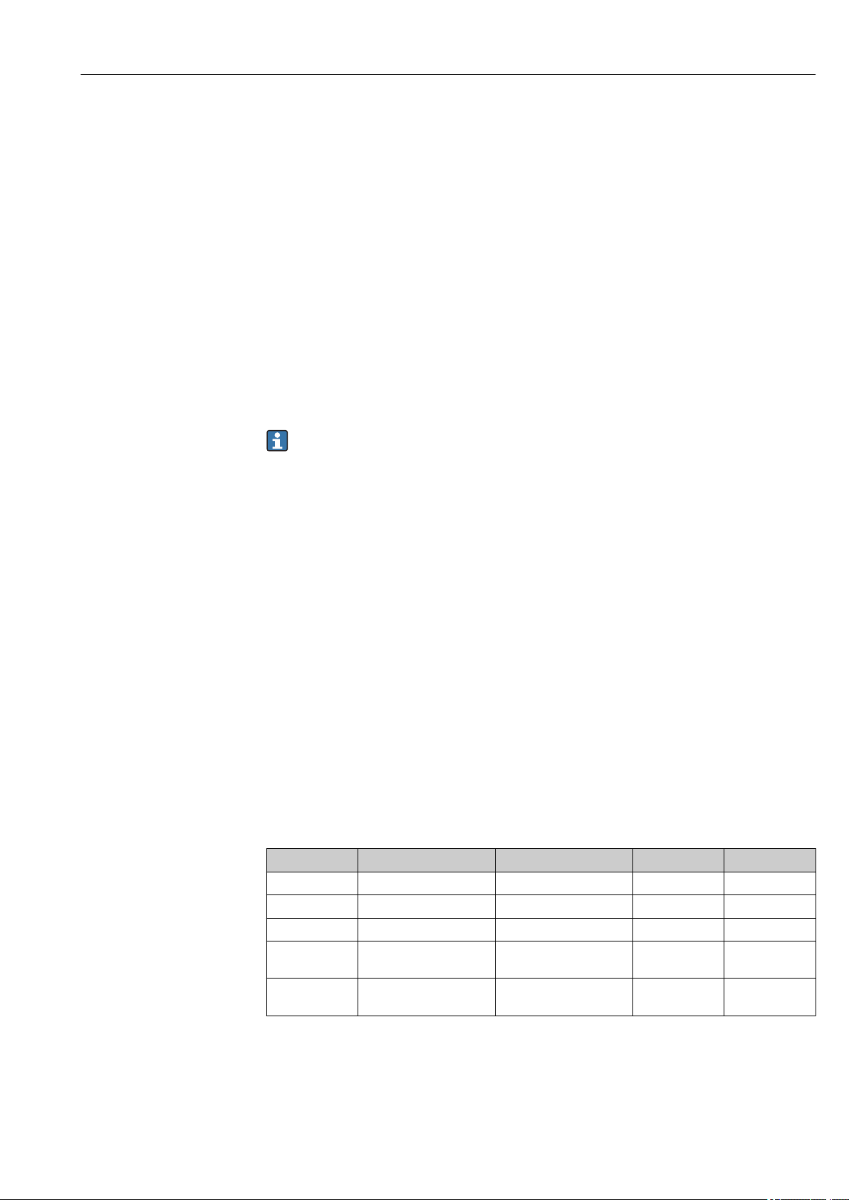
1.5 Terms and abbreviations
1)
Item Term/abbreviation Explanation
1 OPL The OPL (over pressure limit = sensor overload limit) for the measuring device depends on the lowest-rated
element, with regard to pressure, of the selected components, i.e. the process connection has to be taken into
consideration in addition to the measuring cell. Also observe pressure-temperature dependency.
The OPL may only be applied for a limited period of time.
2 MWP The MWP (maximum working pressure) for the sensors depends on the lowest-rated element, with regard to
pressure, of the selected components, i.e. the process connection has to be taken into consideration in addition to
the measuring cell. Also observe pressure-temperature dependency.
The MWP may be applied at the device for an unlimited period.
The MWP can also be found on the nameplate.
3 Maximum sensor
measuring range
4 Calibrated/adjusted span Span between LRV and URV
p - Pressure
- LRL Lower range limit
- URL Upper range limit
- LRV Lower range value
Span between LRL and URL
This sensor measuring range is equivalent to the maximum calibratable/adjustable span.
Factory setting: 0 to URL
Other calibrated spans can be ordered as customized spans.
A0029505
8 Endress+Hauser
Page 9
Waterpilot FMX21 About this document
LRV
URLURV
LRL
1 = 2
3
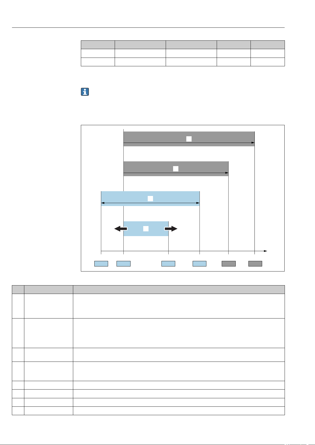
Item Term/abbreviation Explanation
- URV Upper range value
- TD (turn down) Turn down
Example - see the following section.
- PE Polyethylene
- FEP Fluorinated ethylene propylene
- PUR Polyurethane
1.6 Turn down calculation
A0029545
1 Calibrated/adjusted span
2 Zero point-based span
3 URL sensor
Example
• Sensor:10 bar (150 psi)
• Upper range value (URL) = 10 bar (150 psi)
Turn down (TD):
URL
TD =
|URV - LRV|
10 bar (150 psi)
TD =
|5 bar (75 psi) - 0 bar (0 psi)|
In this example, the TD is 2:1.
This span is based on the zero point.
• Calibrated/adjusted span: 0 to 5 bar (0 to 75 psi)
• Lower range value (LRV) = 0 bar (0 psi)
• Upper range value (URV) = 5 bar (75 psi)
= 2
Endress+Hauser 9
Page 10

Basic safety instructions Waterpilot FMX21
2 Basic safety instructions
2.1 Requirements concerning the staff
The personnel for installation, commissioning, diagnostics and maintenance must fulfill
the following requirements:
Trained, qualified specialists: must have a relevant qualification for this specific
‣
function and task
Are authorized by the plant owner/operator
‣
Are familiar with federal/national regulations
‣
Before beginning work, the specialist staff must have read and understood the
‣
instructions in the Operating Instructions and supplementary documentation as well as
in the certificates (depending on the application)
Following instructions and basic conditions
‣
The operating personnel must fulfill the following requirements:
Being instructed and authorized according to the requirements of the task by the
‣
facility's owner-operator
Following the instructions in these Operating Instructions
‣
2.2 Designated use
2.2.1 Application and media
The Waterpilot FMX21 is a hydrostatic pressure sensor for measuring the level of fresh
water, wastewater and salt water. The temperature is measured simultaneously in the case
of sensor versions with a Pt100 resistance thermometer.
An optional temperature head transmitter converts the Pt100 signal to a 4 to 20 mA
signal with superimposed digital communication protocol HART 6.0.
2.2.2 Incorrect use
The manufacturer is not liable for damage caused by improper or non-designated use.
Verification for borderline cases:
For special fluids and fluids for cleaning, Endress+Hauser is glad to provide assistance
‣
in verifying the corrosion resistance of fluid-wetted materials, but does not accept any
warranty or liability.
2.3 Workplace safety
For work on and with the device:
Wear the required personal protective equipment according to federal/national
‣
regulations.
Switch off the supply voltage before connecting the device.
‣
2.4 Operational safety
Risk of injury!
Operate the device in proper technical condition and fail-safe condition only.
‣
The operator is responsible for interference-free operation of the device.
‣
10 Endress+Hauser
Page 11

Waterpilot FMX21 Basic safety instructions
Modifications to the device
Unauthorized modifications to the device are not permitted and can lead to unforeseeable
dangers.
If, despite this, modifications are required, consult with Endress+Hauser.
‣
Repairs
To ensure continued operational safety and reliability,
Carry out repairs on the device only if they are expressly permitted.
‣
Observe federal/national regulations pertaining to repair of an electrical device.
‣
Use original spare parts and accessories from Endress+Hauser only.
‣
Hazardous area
To eliminate danger to persons or the facility when the device is used in the approvalrelated area (e.g. explosion protection, pressure vessel safety):
Check the nameplate to verify if the device ordered can be put to its intended use in the
‣
approval-related area.
Observe the specifications in the separate supplementary documentation that is an
‣
integral part of these Instructions.
2.5 Product safety
This measuring device is designed in accordance with good engineering practice to meet
state-of-the-art safety requirements, has been tested, and left the factory in a condition in
which it is safe to operate.
It meets general safety standards and legal requirements. It also complies with the EC
directives listed in the device-specific EC Declaration of Conformity. Endress+Hauser
confirms this by affixing the CE mark to the device.
Endress+Hauser 11
Page 12
Product description Waterpilot FMX21
h
2
1
p
atm
p
hydr.
p = p + p
atm hydr.
p
atm
p
atm
h ~ p
r • g
h =
p
Rel.: p = (p + p ) - p
sens atm hydr. atm
p = p + p
atm hydr.
Abs.: p = (p + p )
sens atm hydr.
3 Product description
3.1 Function
The ceramic measuring cell is a dry measuring cell i.e. the pressure acts directly on the
robust, ceramic process isolating diaphragm of the Waterpilot FMX21. Changes in air
pressure are guided via a pressure compensation tube through the extension cable to the
rear of the ceramic process isolating diaphragm and are compensated for. A pressuredependent change in capacitance, caused by the movement of the process isolating
diaphragm, is measured at the electrodes of the ceramic carrier. The electronics unit then
converts this to a signal that is proportional to the pressure and linear to the level.
1 Ceramic measuring cell
2 Pressure compensation tube
h Height level
p Total pressure = atmospheric pressure + hydrostatic pressure
ρ Density of the medium
g Acceleration due to gravity
P
Hydrostatic pressure
hydr.
P
Atmospheric pressure
atm
P
Pressure displayed on the sensor
sens
A0019140
12 Endress+Hauser
Page 13
Waterpilot FMX21 Incoming acceptance and product identification
DELIVERY NOTE
1 = 2
Dat./Insp.:
FW.Ver.:
Dev.Rev.:
Cal./Adj.
Mat:
L=
Ser. no.:
Order code:
Ext.order code:
TAG:
Waterpilot FMX21
Made in Germany,D-79689 Maulburg
p
DELIVERYNOTE
Dat./Insp.:
FW.Ver.:
Dev.Rev.:
Cal./Adj.
Mat:
L=
Ser. no.:
Order code:
Ext. order code:
TAG:
Waterpilot FMX21
Made in Germany,D-79689 Maulburg
p
4 Incoming acceptance and product
identification
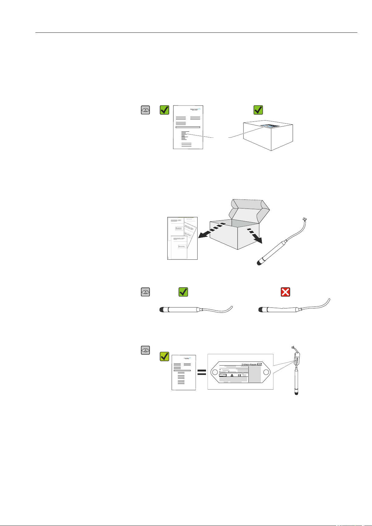
4.1 Incoming acceptance
A0015502
A0016870
Is the order code on the delivery note (1) identical to the order code on
the product sticker (2)?
A0015502
A0015502
A0026535
A0026536
Are the goods undamaged?
A0026537
Do the data on the nameplate correspond to the order specifications and
the delivery note?
Endress+Hauser 13
Page 14
Incoming acceptance and product identification Waterpilot FMX21
A0015502
A0022106
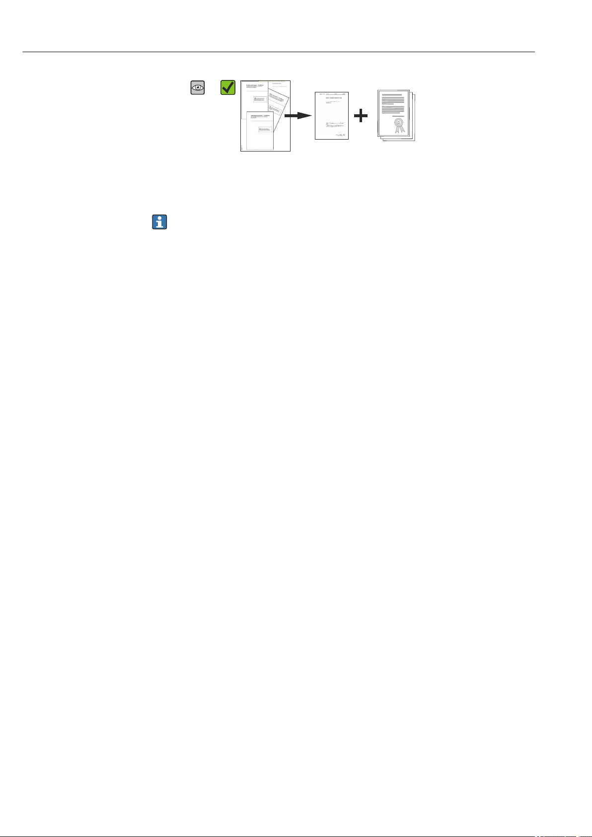
Is the documentation available?
If required (see nameplate): Are the safety instructions (XA) present?
If one of these conditions does not apply, please contact your
Endress+Hauser sales office.
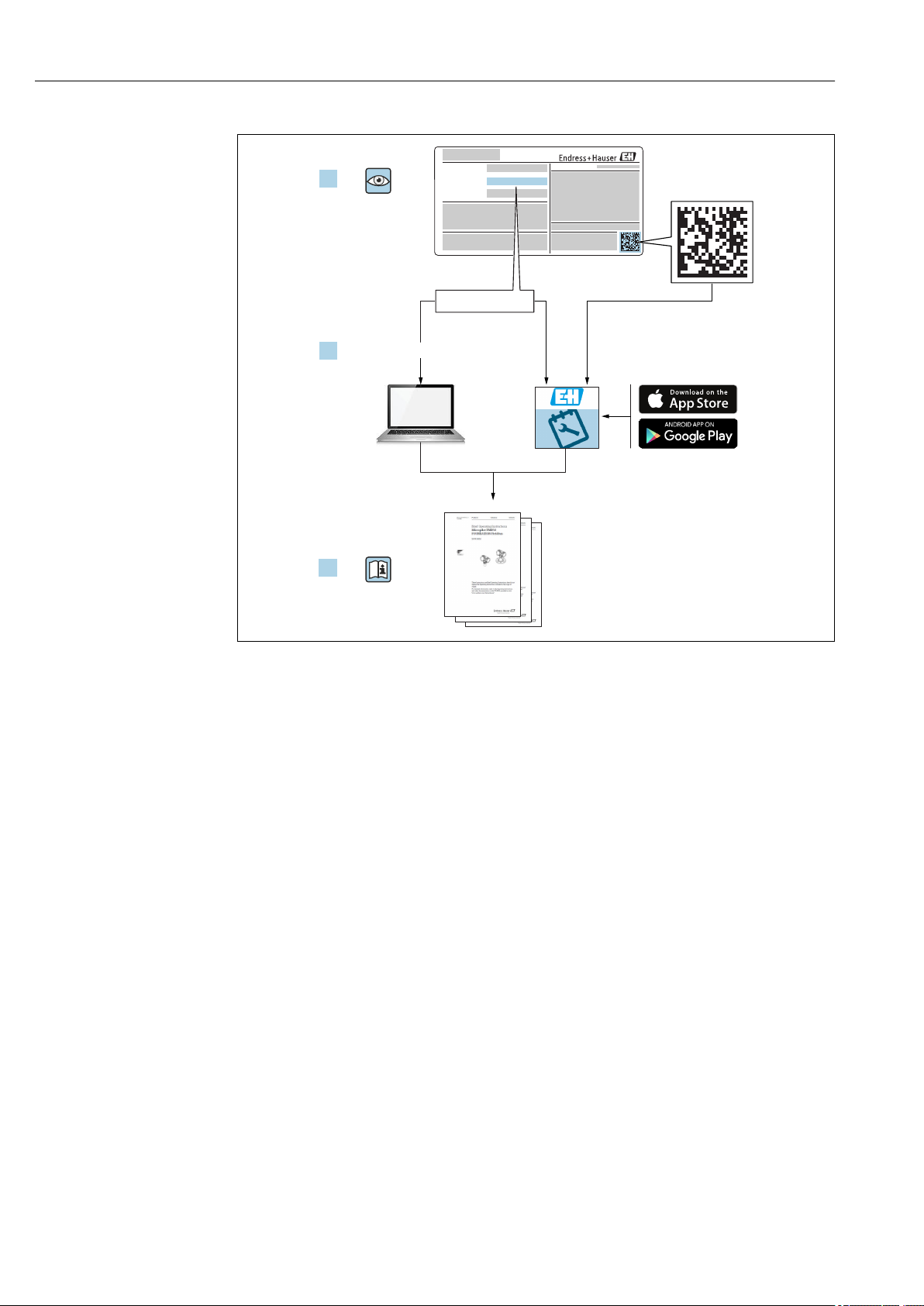
4.2 Product identification
The following options are available for identification of the measuring device:
• Nameplate specifications
• Order code with breakdown of the device features on the delivery note
• Enter serial number of nameplates in W@M Device Viewer
(www.endress.com/deviceviewer): All details on the measuring device are displayed.
For an overview of the technical documentation provided, enter the serial number from
the nameplates in the W@M Device Viewer (www.endress.com/deviceviewer)
4.2.1 Manufacturer address
Endress+Hauser SE+Co. KG
Hauptstraße 1
79689 Maulburg, Germany
Address of the manufacturing plant: See nameplate.
14 Endress+Hauser
Page 15
Waterpilot FMX21 Incoming acceptance and product identification
Dat./Insp.:
FW.Ver.:
Dev.Rev.:
Cal./Adj.
Mat:
L=
Ser. no.:
Order code:
Ext. order code:
TAG:
Waterpilot FMX21
Made in Germany, D-79689 Maulburg
p
1
2
17
16
15
14
3 4
5
6/7
89
101112
13
Mat.: 316L/1.4435/1.4404, Al O , PE, EPDM, PPO
2 3
For use in drinking water according to:
Made in Germany, D-79689 Maulburg
Waterpilot FMX21
250002737-B
1
23
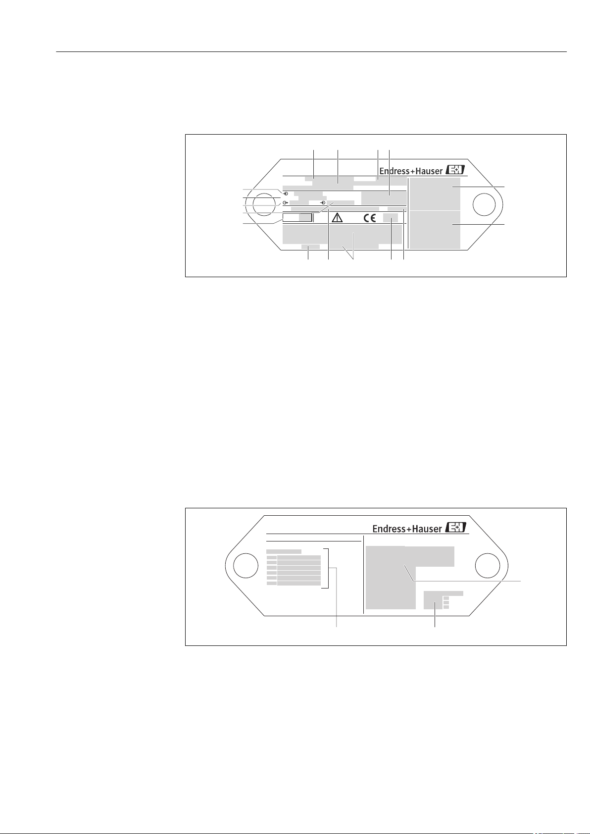
4.3 Nameplates
4.3.1 Nameplates on extension cable
A0018802
1 Order code (shortened for reordering); The meaning of the individual letters and digits is explained in the
order confirmation details.
2 Extended order number (complete)
3 Serial number (for clear identification)
4 TAG (device tag)
5 FMX21 connection diagram
6 Pt100 connection diagram (optional)
7 Warning (hazardous area), (optional)
8 Length of extension cable
9 Approval symbol, e.g. CSA, FM, ATEX (optional)
10 Text for approval (optional)
11 Materials in contact with process
12 Test date (optional)
13 Software version/device version
14 Supply voltage
15 Output signal
16 Set measuring range
17 Nominal measuring range
Additional nameplate for devices with approvals
1 Approval symbol (drinking water approval)
2 Reference to associated documentation
3 Approval number (marine approval)
Endress+Hauser 15
A0018805
Page 16

Incoming acceptance and product identification Waterpilot FMX21
x
Install per dwg. 96000xxxx-
Ser.-No.:
p
Waterpilot FMX21
Cal./Adj.
1 2 3 4 5 6 7
4.3.2 Additional nameplate for devices with external diameter 22 mm (0.87 in) and 42 mm (1.65 in)
A0018804
1 Serial number
2 Nominal measuring range
3 Set measuring range
4 CE mark or approval symbol
5 Certificate number (optional)
6 Text for approval (optional)
7 Reference to documentation
4.4 Identification of sensor type
With gauge pressure or absolute pressure sensors, the "Pos. zero adjust" parameter is
displayed in the operating menu. With absolute pressure sensors, the "Calib. offset"
parameter is displayed in the operating menu.
4.5 Storage and transport
4.5.1 Storage conditions
Use original packaging.
Store the measuring device in clean and dry conditions and protect from damage caused by
shocks (EN 837-2).
Storage temperature range
FMX21 + Pt100 (optional)
–40 to +80 °C (–40 to +176 °F)
Cable
(when mounted in a fixed position)
• With PE: –30 to +70 °C (–22 to +158 °F)
• With FEP: –30 to +80 °C (–22 to +176 °F)
• With PUR: –40 to +80 °C (–40 to +176 °F)
Terminal box
–40 to +80 °C (–40 to +176 °F)
TMT182 temperature head transmitter (optional) for FMX21 4 to 20 mA HART
–40 to +100 °C (–40 to +212 °F)
16 Endress+Hauser
Page 17

Waterpilot FMX21 Incoming acceptance and product identification
4.5.2 Transporting the product to the measuring point
WARNING
L
Incorrect transport!
Device or cable may become damaged, and there is a risk of injury!
Transport measuring device in the original packaging.
‣
Follow the safety instructions and transport conditions for devices weighing more than
‣
18 kg (39.6 lbs).
4.6 Scope of delivery
The scope of delivery comprises:
• Waterpilot FMX21, optionally with integrated Pt100 resistance thermometer
• Optional accessories
Documentation supplied:
• The Operating Instructions BA00380P are available on the internet. → see:
www.de.endress.com → Downloads.
• Brief Operating Instructions KA01189P
• Final inspection report
• Drinking water approvals (optional): SD00289P, SD00319P, SD00320P
• Devices that are suitable for use in hazardous areas: Additional documentation e.g.
Safety instructions (XA, ZD)
Endress+Hauser 17
Page 18
Installation Waterpilot FMX21
1
2
3
4
5
6
7
8
9
Dat./Insp.:
FW.Ver.: xxxx
Dev.Rev.: xxxx
Cal./Adj.
Mat:
L=
Ser. no.:xxxxxxxxxxxxx
Order code: xxxxxxxxxxxxxxxxxxxxxx
Ext. order code:xxxxxxxxxxxxxxxxxxxxxx
TAG:xxxxxxxxxxxxxxxxx
xxxxxxxxxxxxxxxxx
xxxxxxxxxxxxxxxxx
Waterpilot FMX21
Made in Germany,D-79689 Maulburg
p
Ex ia IICT6-T4
£
-10°C Ta 70°C
£
Ta 40°C forT6
£
Ta 70°C forT4
£
Ui 30VDC ; Ii 133mA; Pi 1W
£
£
£
II 2G
Ci= 5nF + 180pF/m ; Li= 1 µH/m
Warning!
Avoid electrostatic
charge
0...400mbar
4... 20 mA
0...600mbar
red
+
black
-
yellow-green
4…20 mA
Sensor
250002736--
10,5... 35VDC
XAxxxxxP-
XX/XXXX
TÜV 01ATEX 1685
PPS/Polyolefin
AL2O3
FEPEPDM
OPEN
CLOSE
90°
90°
Warning:
Avoid electrostatic charge in explosive atmosphere.
See instructions
Terminal Box for FMX21
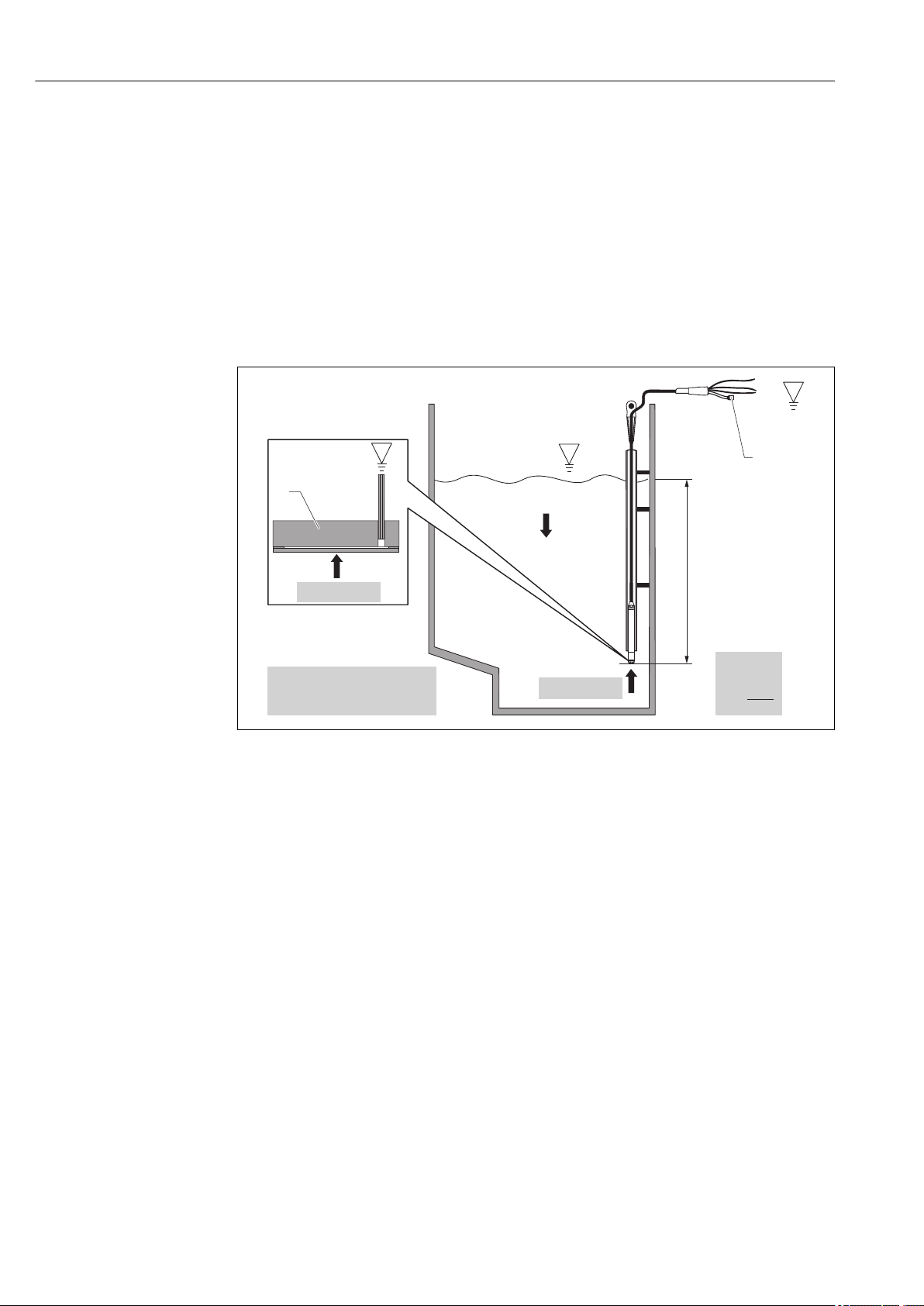
5 Installation
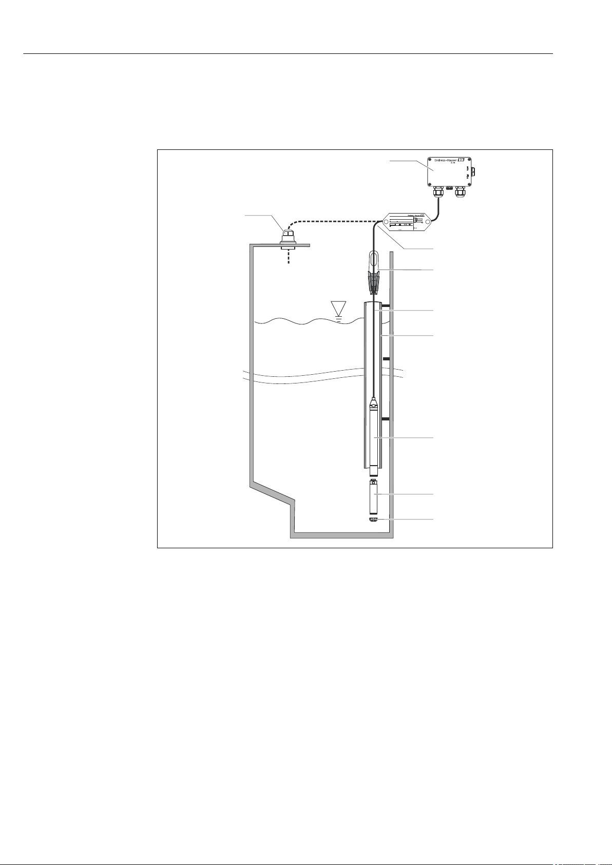
5.1 Installation conditions
A0018770
1 Cable mounting screw (can be ordered as an accessory)
2 Terminal box (can be ordered as an accessory)
3 Bending radius of extension cable > 120 mm (4.72 in)
4 Mounting clamp (can be ordered as an accessory)
5 Extension cable
6 Guide tube
7 Waterpilot FMX21
8 Additional weight can be ordered as an accessory for the FMX21 with external diameter of 22 mm (0.87 in)
and 29 mm (1.14 in)
9 Protection cap
18 Endress+Hauser
Page 19
Waterpilot FMX21 Installation
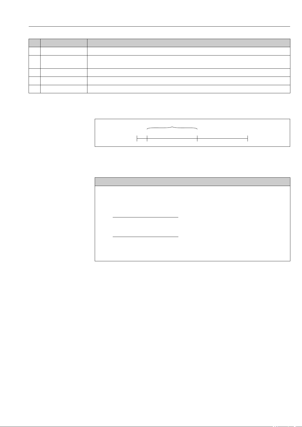
L
E
5.2 Additional mounting instructions
• Cable length
– Customer-specific in meters or feet.
– Limited cable length when performing installation with freely suspended device with
cable mounting screw or mounting clamp, as well as for FM/CSA approval: max.
300 m (984 ft).
• Sideways movement of the level probe can result in measuring errors. For this reason,
install the probe at a point free from flow and turbulence, or use a guide tube. The
internal diameter of the guide tube should be at least 1 mm (0.04 in) greater than the
external diameter of the selected FMX21.
• To avoid mechanical damage to the measuring cell, the device is equipped with a
protection cap.
• The cable must end in a dry room or a suitable terminal box. The terminal box from
Endress+Hauser provides humidity and climatic protection and is suitable for installation
outdoors → 124.
• Cable length tolerance: < 5 m (16 ft): ±17.5 mm (0.69 in); > 5 m (16 ft): ±0.2 %
• If the cable is shortened, the filter at the pressure compensation tube must be
reattached. Endress+Hauser offers a cable shortening kit for this purpose → 124
(documentation SD00552P/00/A6).
• Endress+Hauser recommends using twisted, shielded cable.
• In shipbuilding applications, measures are required to restrict the spread of fire along
cable looms.
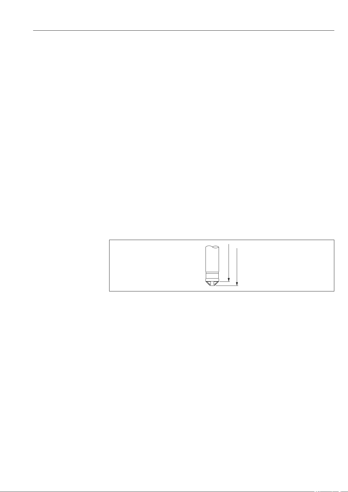
• The length of the extension cable depends on the intended level zero point. The height
of the protection cap must be taken into consideration when designing the layout of the
measuring point. The level zero point (E) corresponds to the position of the process
isolating diaphragm. Level zero point = E; tip of probe = L (see the following diagram).
A0026013
5.3 Dimensions
For dimensions, please refer to the Technical Information TI00431P/00/EN, "Mechanical
construction" section (see also: www.de.endress.com → Downloads → Media Type:
Documentation).
Endress+Hauser 19
Page 20
Installation Waterpilot FMX21
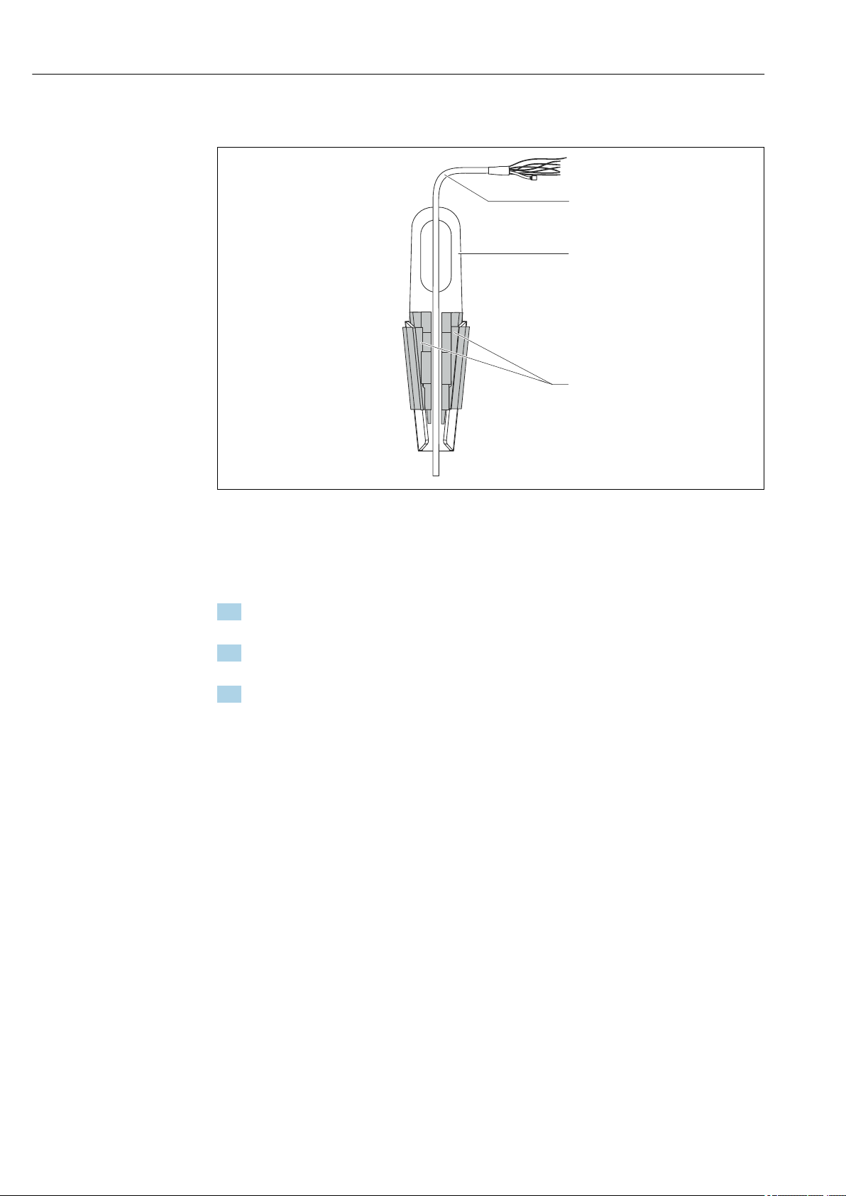
1
2
3
5.4 Mounting the Waterpilot with a mounting clamp
1 Extension cable
2 Suspension clamp
3 Clamping jaws
5.4.1 Mounting the suspension clamp:
1. Mount the suspension clamp (item 2). Take the weight of the extension cable (item
1) and the device into account when selecting the fastening point.
2. Push up the clamping jaws (item 3). Place the extension cable (item 1) between the
clamping jaws as shown in the graphic.
3. Hold the extension cable (item 1) in position and push the clamping jaws (item 3)
back down. Tap the clamping jaws gently from above to fix them in place.
A0018793
20 Endress+Hauser
Page 21
Waterpilot FMX21 Installation
+40
( +1.57)
1
6
8
7
2
3
4
5
36
41
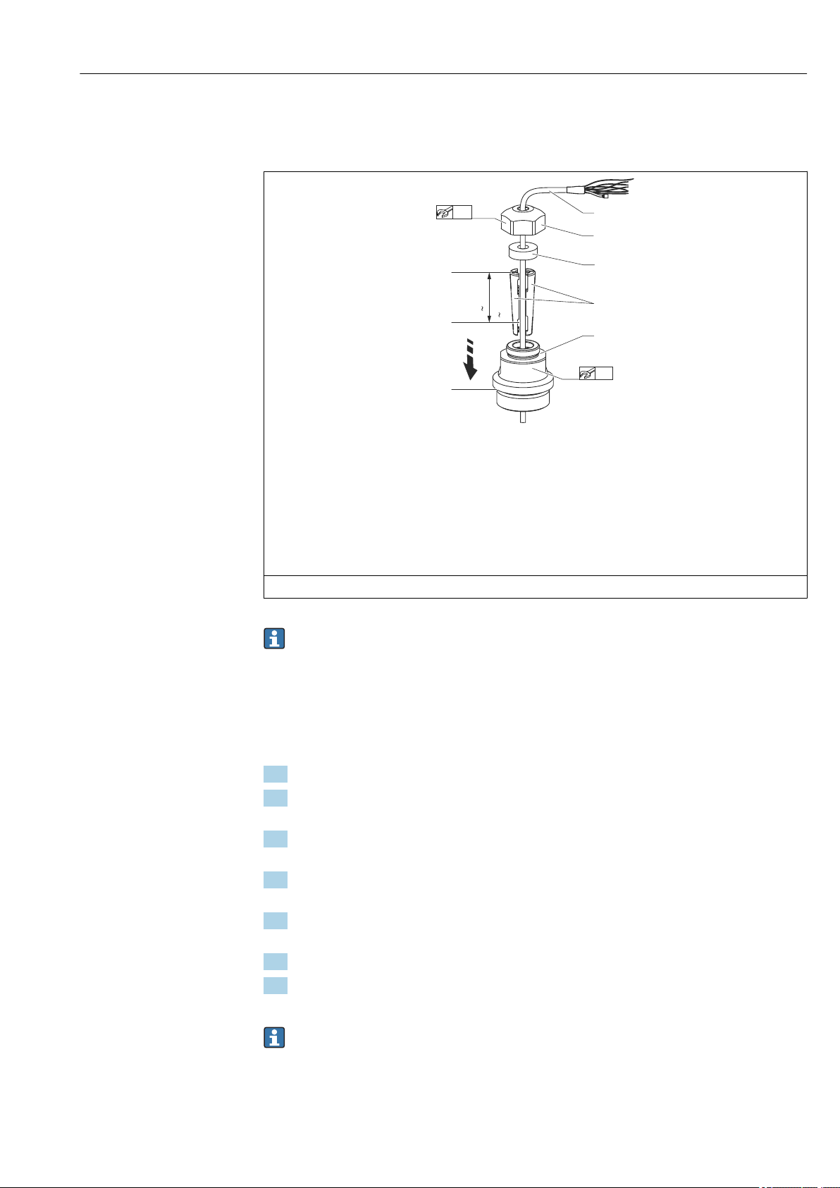
5.5 Mounting the Waterpilot with a cable mounting screw
A0018794
1 Extension cable
2 Cover for cable mounting screw
3 Sealing ring
4 Clamping sleeves
5 Adapter for cable mounting screw
6 Top edge of clamping sleeve
7 Desired length of extension cable and Waterpilot probe prior to assembly
8 After assembly, item 7 is located next to the mounting screw with G 1½" thread: height of sealing surface of
the adapter or NPT 1½" thread height of thread run-out of adapter
Engineering unit mm (in). Illustrated with G 1½" thread.
If you want to lower the level probe to a certain depth, position the top edge of the
clamping sleeve 40 mm (4.57 in) higher than the required depth. Then push the
extension cable and the clamping sleeve into the adapter as described in Step 6 in the
following section.
5.5.1 Mounting the cable mounting screw with a G 1½" or NPT 1½" thread:
1. Mark the desired length of extension cable on the extension cable.
2. Insert the probe through the measuring aperture and carefully lower on the
extension cable. Fix the extension cable to prevent it from slipping.
3. Slide the adapter (item 5) over the extension cable and screw it tightly into the
measuring aperture.
4. Slide the sealing ring (item 3) and cover (item 2) onto the cable from above. Press
the sealing ring into the cover.
5. Place the clamping sleeves (item 4) around the extension cable (item 1) at the
marked point as illustrated in the graphic.
6. Slide the extension cable with the clamping sleeves (item 4) into the adapter (item 5)
7. Fit the cover (item 2) with the sealing ring (item 3) onto the adapter (item 5) and
securely screw together with the adapter.
To remove the cable mounting screw, perform this sequence of steps in reverse.
Endress+Hauser 21
Page 22
Installation Waterpilot FMX21
1
3
2
6
5
4
3
CLOSE
90°
OPEN
90°
Warning:
Avoid electrostatic charge in explosive atmosphere.
See instructions
Terminal Box for FMX21
1
2
3
4
5
CAUTION
L
Risk of injury!
Use only in unpressurized vessels.
‣
5.6 Mounting the terminal box
The optional terminal box is mounted using four screws (M4). For the dimensions of the
terminal box, please see the Technical Information TI00431P/00/ EN, "Mechanical
construction" section (see also: www.de.endress.com → Downloads → Media Type:
Documentation).
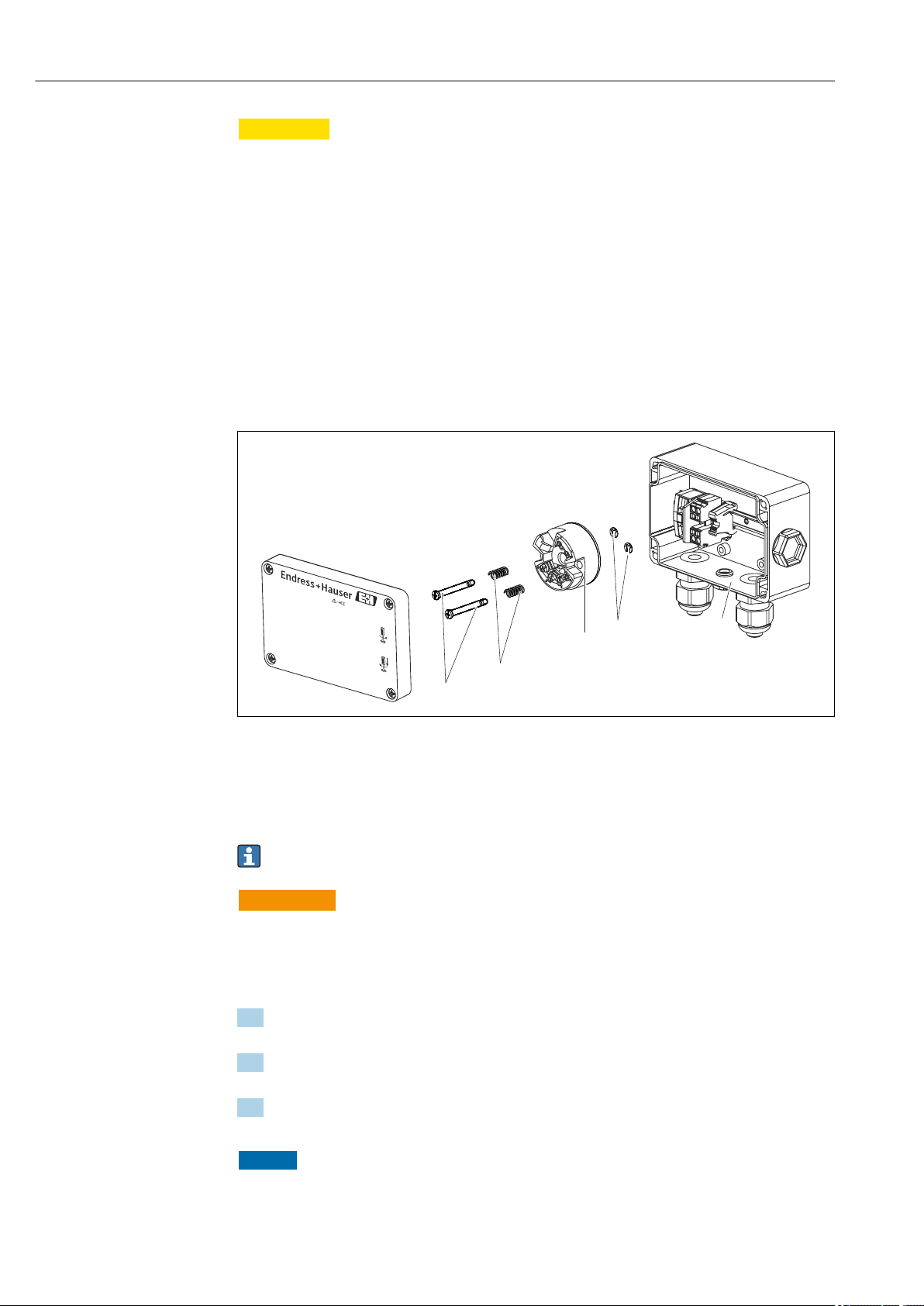
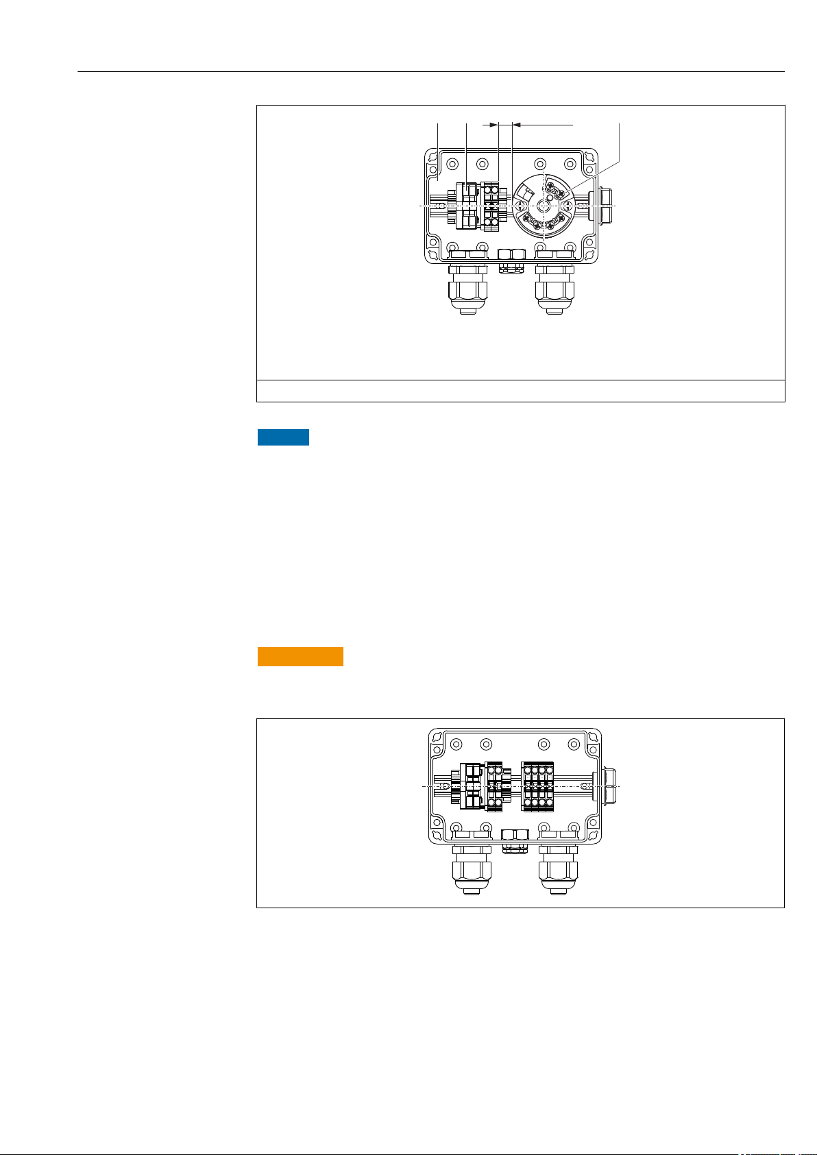
5.7 Mounting the TMT182 temperature head transmitter with terminal box
1 Mounting screws
2 Mounting springs
3 TMT182 temperature head transmitter
4 Circlips
5 Terminal box
Only open the terminal box with a screwdriver.
WARNING
L
Risk of explosion!
The TMT182 is not designed for use in hazardous areas.
‣
5.7.1 Mounting the temperature head transmitter:
1. Guide the mounting screws (item 1) with the mounting springs (item 2) through the
bore of the temperature head transmitter (item 3)
2. Secure the mounting screws with the circlips (item 4). Circlips, mounting screws and
springs are included in the scope of delivery for the temperature head transmitter.
3. Screw the temperature head transmitter into the field housing tightly. (Width of
screwdriver blade max. 6 mm (0.24 in))
NOTICE
22 Endress+Hauser
Avoid damage to the temperature head transmitter.
Do not overtighten the mounting screw.
‣
A0018813
Page 23
Waterpilot FMX21 Installation
>7 (0.28)1 2 3
A0018696
1 Terminal box
2 Terminal strip
3 TMT182 temperature head transmitter
Engineering unit mm (in)
NOTICE
Incorrect connection!
A distance of >7 mm (> 0.28) must be maintained between the terminal strip and the
‣
TMT182 temperature head transmitter.
5.8 Mounting the terminal strip for the Pt100 passive (without TMT182)
If the FMX21 with optional Pt100 is supplied without the optional TMT182 temperature
head transmitter, a terminal strip is provided with the terminal box for the purpose of
wiring the Pt100.
WARNING
L
Risk of explosion!
The Pt100, as well as the terminal strip, are not designed for use in hazardous areas.
‣
A0018815
Endress+Hauser 23
Page 24
Installation Waterpilot FMX21
TX20
2.
3.
4.
1.
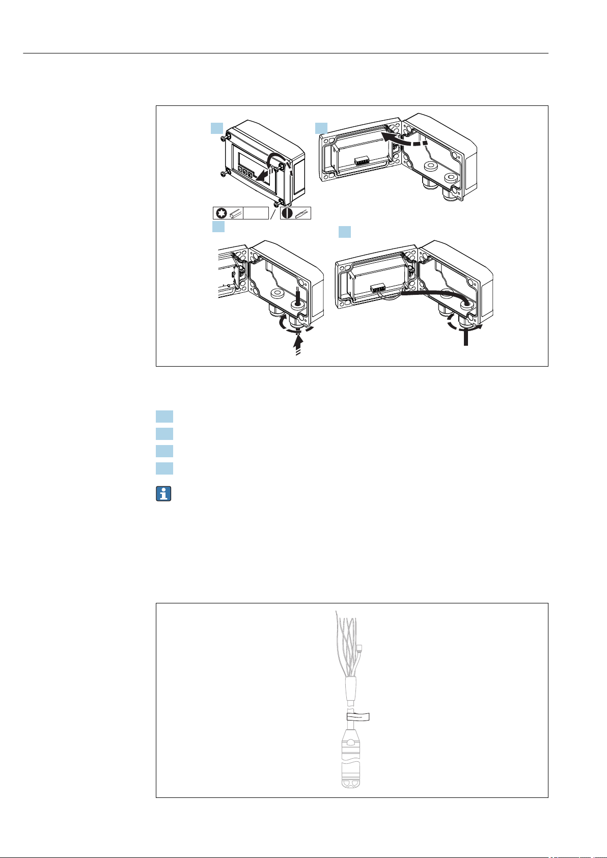
5.9 Inserting the cable into the RIA15 field housing
A0017830
Inserting the cable, field housing, connection without transmitter power supply (example)
1. Release the housing screws
2. Open the housing
3. Open the cable gland (M16) and insert the cable
4. Connect the cable including the functional grounding and close the cable gland
Compensation of the atmospheric pressure must be ensured for the installation. A
black, vented cable gland is supplied for this purpose.
If using the communication resistor module in the RIA15, the cable of the FMX21
must be inserted into the right gland when connecting the FMX21 so that the
integrated pressure compensation tube is not pinched.
5.10 Cable marking
24 Endress+Hauser
A0030955
Page 25
Waterpilot FMX21 Installation
• To make installation easier, Endress+Hauser marks the extension cable if a customer-
specific length has been ordered.
Ordering information: Product Configurator order code for "Service", option "IR" or "IS".
• Cable marking tolerance (distance to lower end of level probe):
Cable length < 5 m (16 ft): ±17.5 mm (0.69 in)
Cable length > 5 m (16 ft): ±0.2 %
• Material: PET, stick-on label: acrylic
• Immunity to temperature change: –30 to +100 °C (–22 to +212 °F)
NOTICE
The marking is used exclusively for installation purposes.
The mark must be thoroughly removed without trace in the case of devices with
‣
drinking water approval. The extension cable must not be damaged in the process.
Not for use of the FMX21 in hazardous areas.
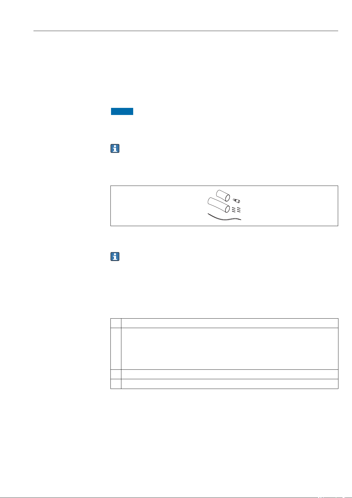
5.11 Cable shortening kit
A0030948
The cable shortening kit is used to shorten a cable easily and professionally.
The cable shortening kit is not designed for the FMX21 with FM/CSA approval.
• Ordering information: Product Configurator order code for "Accessories enclosed", option
"PW"
• Associated documentation SD00552P/00/A6.
5.12 Post-installation check
Is the device undamaged (visual inspection)?
Does the device conform to the measuring point specifications?
For example:
• Process temperature
• Process pressure
• Ambient temperature
• Measuring range
Are the measuring point identification and labeling correct (visual inspection)?
Check that all screws are firmly seated.
Endress+Hauser 25
Page 26
Electrical connection Waterpilot FMX21
RD
BK
RD
BK
WH
YE BU
BR
a
A B
e
)
)
)
)
c
c
d
d
b
b
a
FMX21
FMX21
6 Electrical connection
WARNING
L
Electrical safety is compromised by an incorrect connection!
When using the measuring device in a hazardous area, the relevant national standards
‣
and guidelines as well as the Safety Instructions (XAs) or installation or control
drawings (ZDs) must be adhered to. All data relating to explosion protection can be
found in separate documentation which is available on request. This documentation is
supplied with the devices as standard → 7
6.1 Connecting the device
WARNING
L
Electrical safety is compromised by an incorrect connection!
The supply voltage must match the supply voltage specified on the nameplate → 15
‣
Switch off the supply voltage before connecting the device.
‣
The cable must end in a dry room or a suitable terminal box. The IP66/IP67 terminal
‣
box with GORE-TEX® filter from Endress+Hauser is suitable for outdoor
installation.→ 22
Connect the device in accordance with the following diagrams. Reverse polarity
‣
protection is integrated in the Waterpilot FMX21 and the temperature head
transmitter. Changing the polarities will not result in the destruction of the devices.
A suitable circuit breaker should be provided for the device in accordance with IEC/EN
‣
61010.
6.1.1 Waterpilot with Pt100
A Waterpilot FMX21
B Waterpilot FMX21 with Pt100 (not for use in hazardous areas); option "NB", Product Configurator order code
for "Accessories"
a Not for the FMX21 with external diameter of 29 mm (1.14 in)
b 10.5 to 30 V DC (hazardous area), 10.5 to 35 V DC
c 4...20 mA
d Resistance (RL)
e Pt100
A0019441
26 Endress+Hauser
Page 27
Waterpilot FMX21 Electrical connection
)
a
b
c
e
f
d
cd
g
RD BKWHYE
BU
BR
2
1
6
5
4
3
)
FMX21 4...20 mA HART
6.1.2 Waterpilot with Pt100 and TMT182 temperature head transmitter for FMX21 4 to 20 mA HART
a Not for the FMX21 with external diameter of 29 mm (1.14 in)
b 10.5 to 35 V DC
c 4...20 mA
d Resistance (RL)
e TMT182 temperature head transmitter (4 to 20 mA) (not for use in hazardous areas)
f 11.5 to 35 V DC
g Pt100
1...6 Pin assignment
Ordering information:
Pt100: Product Configurator order code for "Accessories mounted", option "NB"
TMT182: Product Configurator order code for "Accessories enclosed", option "PT"
A0018780
Endress+Hauser 27
Page 28
Electrical connection Waterpilot FMX21
Y
I
R
s
DC
1
2
3
LED
-
+
Y
I
R
s
DC
1
2
3
LED
-
+
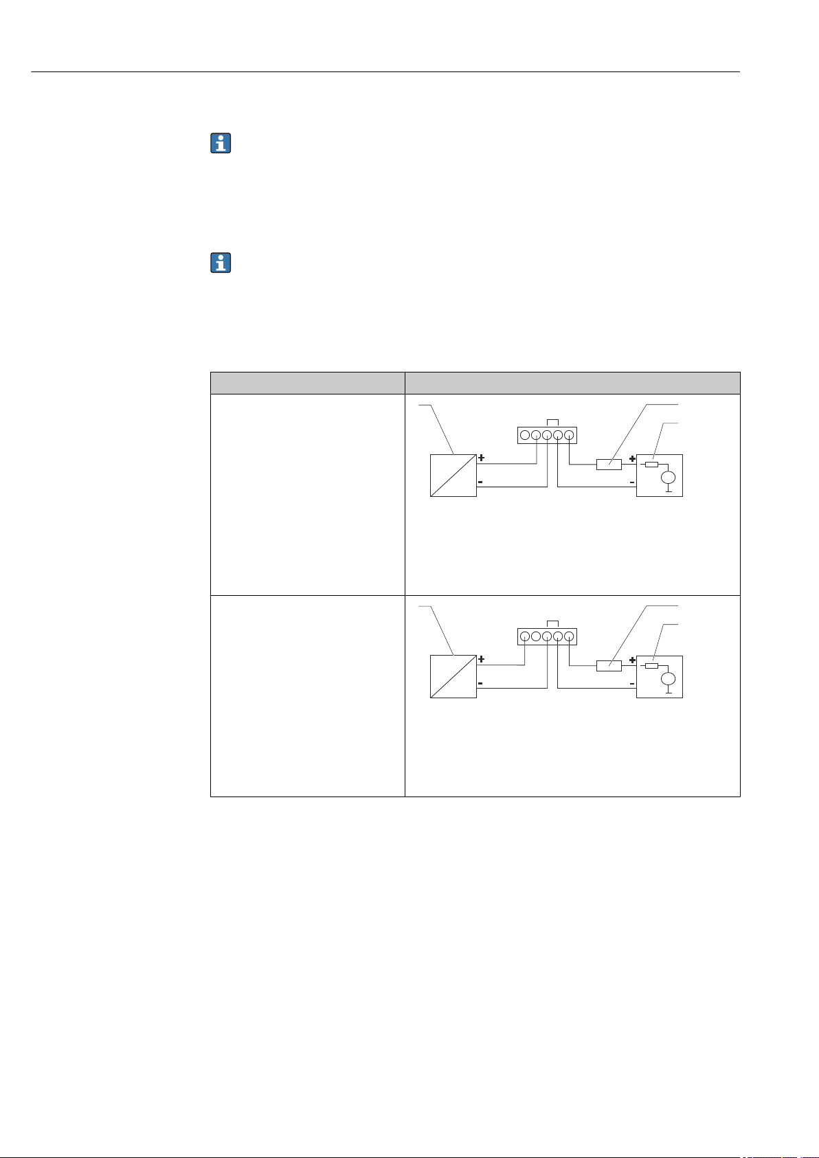
6.1.3 Waterpilot FMX21 with RIA15
The RIA15 remote display can be ordered together with the device.
Product structure, feature 620 "Accessory enclosed":
• Option R4 "Remote display RIA15 non-hazardous area, field housing"
• Option R5 "Remote display RIA15 Ex= explosion protection approval, field housing"
Compensation of the atmospheric pressure must be ensured for the installation. A black,
vented cable gland is supplied for this purpose.
The RIA15 process display unit is loop-powered and does not require any external
power supply.
The voltage drop to be taken into account is:
• ≤1 V in the standard version with 4 to 20 mA communication
• ≤1.9 V with HART communication
• and an additional 2.9 V if display light is used
Circuit diagram / Description
Waterpilot FMX21 connection, HART
communication and RIA15 without
backlight
Waterpilot FMX21 connection, HART
communication and RIA15 with
backlight
A0019567
1 Waterpilot FMX21 block diagram, HART with RIA15 process
display unit without light
1 Waterpilot FMX21
2 Power supply
3 HART resistance
A0019568
2 Waterpilot FMX21 block diagram, HART with RIA15 process
display unit with light
1 Waterpilot FMX21
2 Power supply
3 HART resistance
28 Endress+Hauser
Page 29
Waterpilot FMX21 Electrical connection
1
LED
-
+
3
2
Y
I
R
s
DC
1
3
2
Y
I
R
s
DC
LED
-
+
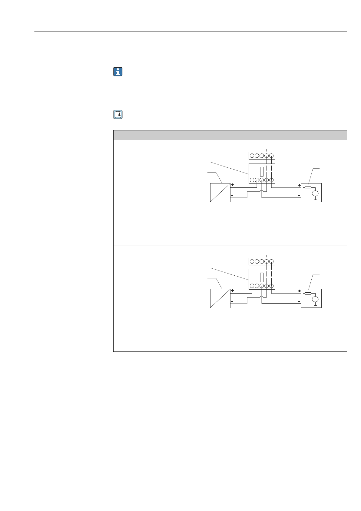
6.1.4 Waterpilot FMX21, RIA15 with installed HART communication resistor module
The HART communication module for installation in the RIA15 can be ordered
together with the device.
Product structure, feature 620 "Accessory enclosed":
• Option R6 "HART communication resistor hazardous / non-hazardous area"
• The voltage drop to be taken into account is max. 7 V
Compensation of the atmospheric pressure must be ensured for the installation. A
black, vented cable gland is supplied for this purpose.
Circuit diagram / Description
Waterpilot FMX21 connection and
RIA15 without backlight
3 Waterpilot FMX21 block diagram, RIA15 without light, HART
communication resistor module
1 HART communication resistor module
2 Waterpilot FMX21
3 Power supply
Waterpilot FMX21 connection and
RIA15 with backlight
4 Waterpilot FMX21 block diagram, RIA15 with light, HART
communication resistor module
1 HART communication resistor module
2 Waterpilot FMX21
3 Power supply
6.1.5 Wire colors
RD = red, BK = black, WH = white, YE = yellow, BU = blue, BR = brown
A0020839
A0020840
6.1.6 Connection data
Connection classification as per IEC 61010-1:
• Overvoltage category 1
• Pollution level 1
Connection data in the hazardous area
See relevant XA.
Endress+Hauser 29
Page 30

Electrical connection Waterpilot FMX21
6.2 Supply voltage
WARNING
L
Supply voltage might be connected!
Risk of electric shock and/or explosion!
When using the measuring device in hazardous areas, installation must comply with
‣
the corresponding national standards and regulations as well as the Safety Instructions.
All explosion protection data are given in separate documentation which is available
‣
upon request. The Ex documentation is supplied as standard with all devices approved
for use in explosion hazardous areas.
6.2.1 FMX21 + Pt100 (optional)
• 10.5 to 35 V (not hazardous areas)
• 10.5 to 30 V (hazardous areas)
6.2.2 TMT182 temperature head transmitter (optional) for FMX21 4 to 20 mA HART
11.5 to 35 V DC
6.3 Cable specifications
Endress+Hauser recommends using shielded, twisted-pair two-wire cables.
The probe cables are shielded for device versions with outer diameters of 22 mm
(0.87 in) and 42 mm (1.65 in).
6.3.1 FMX21 + Pt100 (optional)
• Commercially available instrument cable
• Terminals, terminal box: 0.08 to 2.5 mm2 (28 to 14 AWG)
6.3.2 TMT182 temperature head transmitter (optional) for FMX21 4 to 20 mA HART
• Commercially available instrument cable
• Terminals, terminal box: 0.08 to 2.5 mm2 (28 to 14 AWG)
• Transmitter connection: max. 1.75 mm2 (15 AWG)
6.4 Power consumption
6.4.1 FMX21 + Pt100 (optional)
• ≤ 0.805 W at 35 V DC (non-hazardous area)
• ≤ 0.690 W at 30 V DC (hazardous area)
6.4.2 TMT182 temperature head transmitter (optional) for FMX21 4 to 20 mA HART
≤ 0.805 W at 35 V DC
30 Endress+Hauser
Page 31

Waterpilot FMX21 Electrical connection
6.5 Current consumption
6.5.1 FMX21 + Pt100 (optional)
Max. current consumption: ≤ 23 mA
Min. current consumption: ≥ 3.6 mA
6.5.2 TMT182 temperature head transmitter (optional) for FMX21 4 to 20 mA HART
• Max. current consumption: ≤ 23 mA
• Min. current consumption: ≥ 3.5 mA
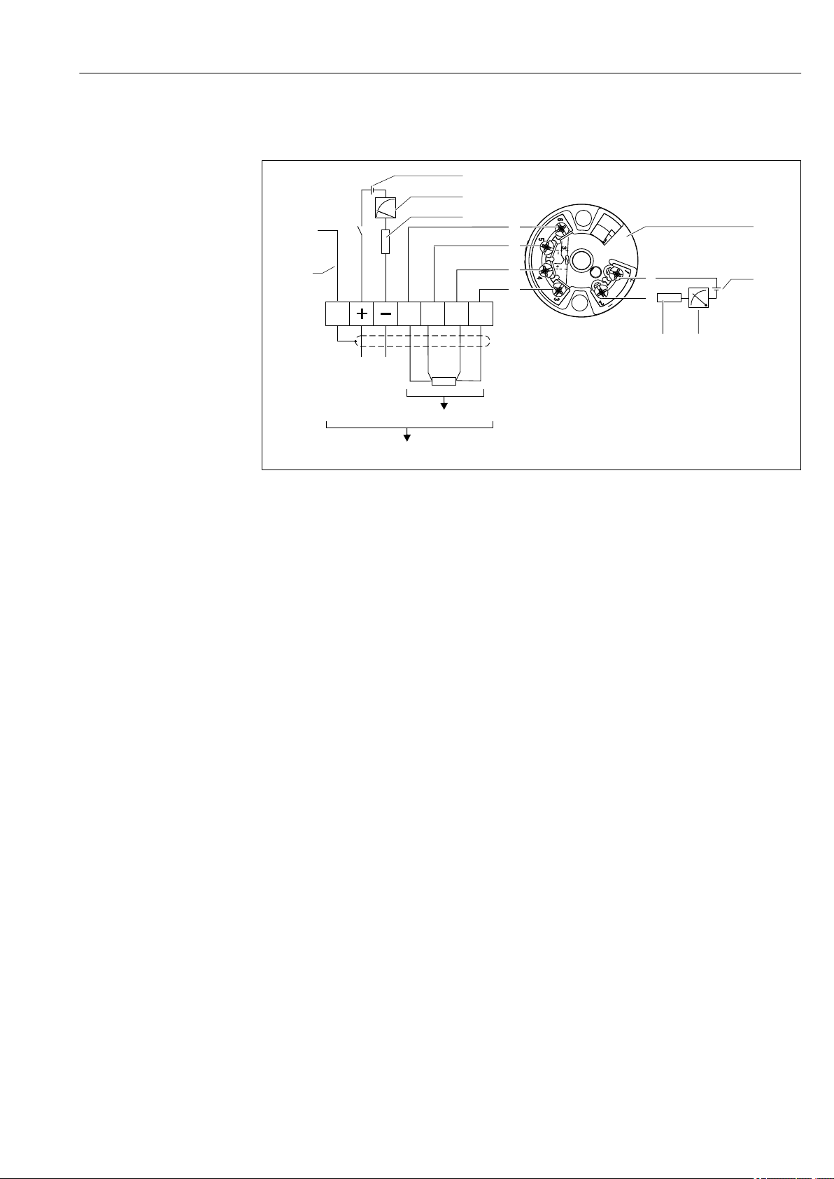
6.6 Connecting the measuring unit
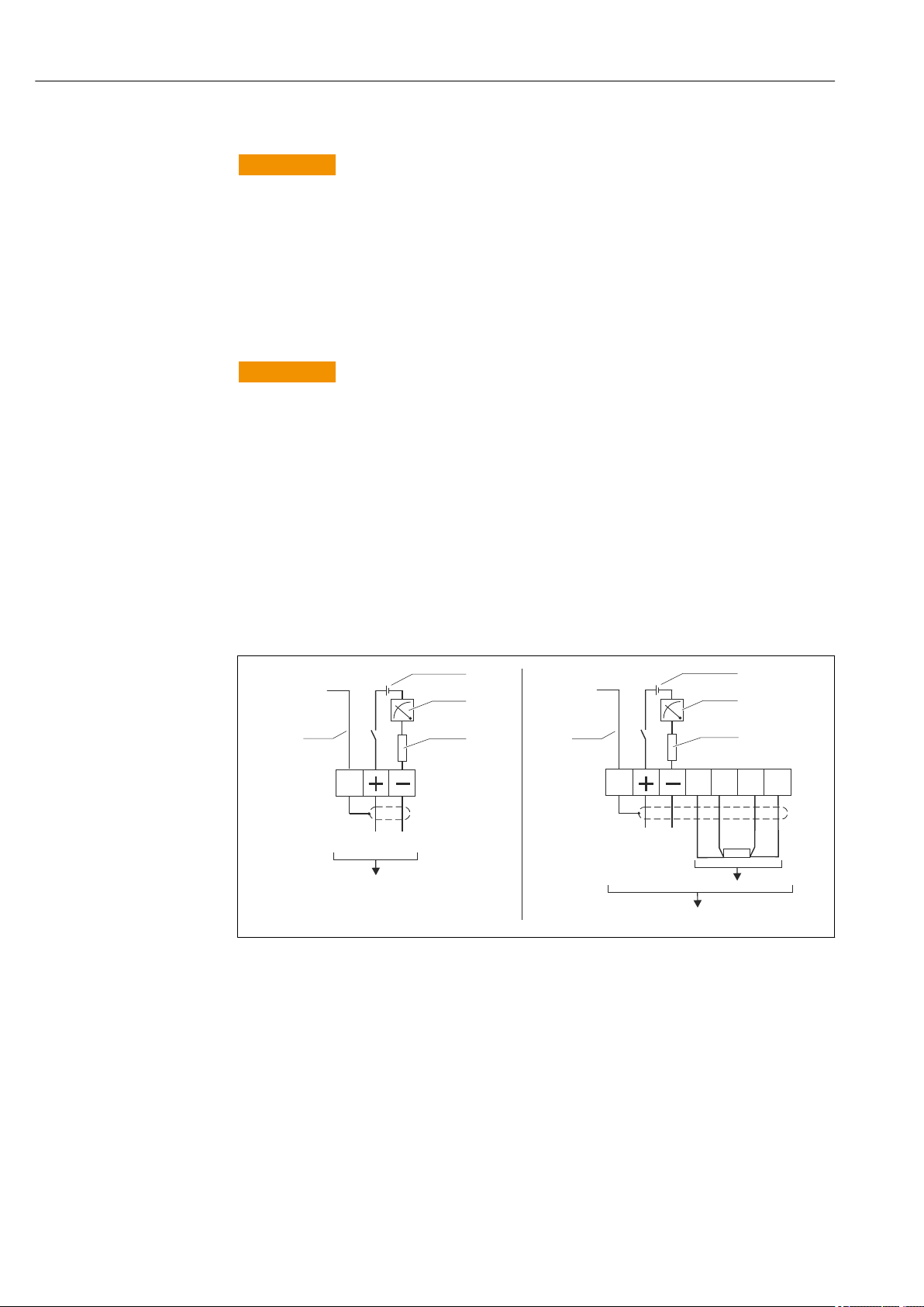
6.6.1 Overvoltage protection
To protect the Waterpilot and the TMT182 temperature head transmitter from large
interference voltage peaks, Endress+Hauser recommends installing overvoltage protection
upstream and downstream of the display and/or evaluation unit as shown in the graphic.
Endress+Hauser 31
Page 32

Electrical connection Waterpilot FMX21
1
3
4
3
4
5
5
5
5
5
5
5
6
6
6
2
A
B
B
C
2
A Power supply, display and evaluation unit with one input for Pt100
B Power supply, display and evaluation unit with one input for 4 to 20 mA
C Power supply, display and evaluation unit with two inputs for 4 to 20 mA
1 Waterpilot FMX21 HART
2 Connection for integrated Pt100 in the FMX21
3 4 to 20 mA HART (temperature)
4 4 to 20 mA HART (level)
5 Overvoltage protection, e.g. HAW from Endress+Hauser (not for use in hazardous areas.)
6 Power supply
Further information on the TMT182 temperature head transmitter for HART
applications from Endress+Hauser can be found in the Technical Information
TI00078R/09/EN.
6.6.2 Connecting the Commubox FXA195
interface of a computer. This enables remote operation of the transmitter using the
The Commubox FXA195 connects transmitters with the HART protocol to the USB
Endress+Hauser operating program FieldCare/DeviceCare. Power is supplied to the
Commubox via the USB port. The Commubox is also suitable for connecting to intrinsically
safe circuits. For further information, see the Technical Information TI00404F/00/EN.
6.6.3 Connecting the Field Xpert SFX
32 Endress+Hauser
Compact, flexible and robust industrial handheld terminal for remote configuration and for
obtaining measured values via the HART current output (4 to 20 mA). For details, see
Operating Instructions BA00060S/04/EN.
A0018941
Page 33

Waterpilot FMX21 Electrical connection
3
7 6
4
5
2
FXN520
1
2
3
4
1 Waterpilot FMX21
2 Required communication resistor ≥ 250 Ω
3 Computer with operating tool (e.g. FieldCare)
4 Commubox FXA195 (USB)
5 Transmitter power supply unit, e.g. RN221N (with communication resistor)
6 Field Xpert SFX
7 VIATOR Bluetooth modem with connecting cable
Only use certified operating devices in hazardous area!
WARNING
L
Risk of explosion!
Do not change the battery of the handheld terminal in the hazardous area.
‣
When using the measuring device in hazardous areas, installation must comply with
‣
the corresponding national standards and regulations and the Safety Instructions (XAs)
or the Installation or Control Drawings (ZDs).
6.6.4 Connecting for air pressure compensation with external measured value
A0018811
1 Fieldgate FXA520
2 Multidrop Connector FXN520
Endress+Hauser 33
3 Cerabar
4 Waterpilot FMX21
A0018757
Page 34

Electrical connection Waterpilot FMX21
1
2
3
4
FXN520
For applications in which condensation may occur, the use of an absolute pressure probe is
recommended. For level measurement using an absolute pressure probe, the measured
value is affected by fluctuations in the ambient air pressure. To correct the resulting
measured error, you can connect an external absolute pressure sensor (e.g. Cerabar) to the
HART signal line, switch the Waterpilot to burst mode and operate the Cerabar in the
"Electr. Delta P" mode.
When you switch on the "Electr. Delta P" application, the external absolute pressure sensor
calculates the difference between the two pressure signals and can thus determine the
level precisely. Only one level measured value can be corrected in this way.
For additional information, see → 57.
If using intrinsically safe devices, the regulations which apply to interconnecting
intrinsically safe circuits as outlined in IEC 60079-14 (proof of intrinsic safety) must
be observed.
6.6.5 Connecting an external temperature sensor/temperature head transmitter for density compensation
The Waterpilot FMX21 can correct measured errors that result from fluctuations in the
density of the water caused by temperature. Users can choose from the following options:
Use the internally measured sensor temperature of the FMX21
The internally measured sensor temperature is calculated in the Waterpilot FMX21 for
density compensation. The level signal is thus corrected according to the density
characteristic line of water.
Use the optional internal Pt100 temperature sensor for density compensation in a
suitable HART master (e.g. PLC)
The Waterpilot FMX21 is available with an optional Pt100 temperature sensor. Endress
+Hauser additionally offers the TMT182 temperature head transmitter to convert the
Pt100 signal to a 4 to 20 mA HART signal. The temperature and pressure signal is queried
by a HART master (e.g. PLC), where a corrected level value can be generated using a stored
linearization table or density function (of a chosen medium).
A0018763
1 HART master, e.g. PLC (programmable logic controller)
2 Multidrop Connector FXN520
3 TMT182 temperature head transmitter
4 Waterpilot FMX21
Use an external temperature signal which is transmitted to the FMX21 via HART
burst mode
The Waterpilot FMX21 is available with an optional Pt100 temperature sensor. With this
option, the signal of the Pt100 is evaluated with a HART-compliant temperature head
transmitter (min. HART 5.0) that supports the burst mode. The temperature signal can
34 Endress+Hauser
Page 35

Waterpilot FMX21 Electrical connection
FXN520
4
1
2
3
thus be transmitted to the FMX21. The FMX21 uses this signal for density correction of
the level signal.
The TMT182 temperature head transmitter is not suitable for this configuration.
A0018764
1 Fieldgate FXA520
2 Multidrop Connector FXN520
3 HART-compatible temperature transmitter (e.g. TMT82)
4 Waterpilot FMX21
Without additional compensation due to the anomaly of water, errors of up to 4% may
occur at a temperature of +70 °C (+158 °F), for example. With density compensation, this
error can be decreased to 0.5 % in the entire temperature range from
0 to +70 °C (+32 to +158 °F).
For additional information, see → 59.
For further information on the devices, please refer to the relevant Technical
Information:
• TI01010T: TMT82 temperature transmitter (4 to 20 mA HART)
• TI00369F: Fieldgate FXA520
• TI00400F: Multidrop Connector FXN520
6.7 Post-connection check
Is the device or cable undamaged (visual check)?
Do the cables comply with the requirements ?
Do the cables have adequate strain relief?
Are all cable glands installed, securely tightened and leak-tight?
Does the supply voltage match the specifications on the nameplate?
Is the terminal assignment correct ?
Endress+Hauser 35
Page 36

Operation options Waterpilot FMX21
7 Operation options
Endress+Hauser offers comprehensive measuring point solutions with display and/or
evaluation units for the Waterpilot FMX21 HART and TMT182 temperature head
transmitter.
Your Endress+Hauser service organization would be glad to be of service if you have
any other questions. Contact addresses can be found on the website at
www.endress.com/worldwide
7.1 Overview of operating options
7.1.1 Operation using Endress+Hauser operating program
FieldCare
The FieldCare operating program is an Endress+Hauser asset management tool based on
FDT technology. With FieldCare, you can configure all Endress+Hauser devices as well as
devices from other manufacturers that support the FDT standard.
Hardware and software requirements can be found on the Internet:
www.de.endress.com → Search: FieldCare → FieldCare → Technical data.
FieldCare supports the following functions:
• Configuration of transmitters in online/offline mode
• Loading and saving device data (upload/download)
• Documentation of the measuring point
Connection options:
• HART via Commubox FXA195 and USB interface of a computer
• HART via Fieldgate FXA520
• Further information on FieldCare and software download can be found on the
internet (www.de.endress.com ® Downloads ® Text Search: FieldCare).
• Connecting the Commubox FXA195
• As not all internal device dependencies can be mapped in offline operation, the
consistency of the parameters must be checked once again before they are
transmitted to the device.
DeviceCare
Function scope
Tool for connecting and configuring Endress+Hauser field devices.
The fastest way to configure Endress+Hauser field devices is with the dedicated
"DeviceCare" tool. Together with the device type managers (DTMs) it presents a convenient,
comprehensive solution.
For details, see Innovation brochure IN01047S
7.1.2 Operation via Field Xpert SFX
Compact, flexible and robust industrial handheld terminal for remote configuration and for
obtaining measured values via the HART current output or FOUNDATION Fieldbus. For
details, see the Operating Instructions BA00060S/04.
36 Endress+Hauser
Page 37

Waterpilot FMX21 Operation options
1
4
6
2
3
5
7.1.3 Operation via RIA15
The RIA15 can be used as a local display unit and for the basic configuration of the
Waterpilot FMX21 hydrostatic level sensor via HART.
The following parameters can be configured on the FMX21 using the 3 operating keys on
the front of the RIA15:
• Pressure engineering unit, level, temperature
• Zero adjustment (only for gauge pressure sensors)
• Empty and full pressure adjustment
• Empty and full level adjustment
• Reset to factory defaults
Further information on the operating parameters → 67
A0035931
5 Remote operation of the Waterpilot FMX21 via the RIA15
1 PLC
2 Transmitter power supply, e.g. RN221N (with communication resistor)
3 Connection for Commubox FXA195 and Field Communicator 375, 475
4 RIA15 loop-powered process display unit
5 Cable gland M16 with pressure compensation membrane
6 Waterpilot FMX21
7.2 Operating concept
Operation with an operating menu is based on an operation concept with "user roles" .
User role Meaning
Operator Operators are responsible for the devices during normal "operation". This is usually limited to the
reading of process values. If the work with the devices goes beyond reading, it concerns simple,
application-specific functions that are used in operation. Should an error occur, these users
simple forward the information on the errors but do not intervene themselves.
Maintenance Service engineers usually work with the devices in the phases following device commissioning.
They are primarily involved in maintenance and troubleshooting activities for which simple
settings have to be made at the device. Technicians work with the devices over the entire life
cycle of the product. Thus, commissioning and advanced settings and configurations are some of
the tasks they have to carry out.
Expert Experts work with the devices over the entire life cycle of the device, but, in part, have high
requirements on the devices. Individual parameters/functions from the overall functionality of
the devices are required for this purpose time and again. In addition to technical, processoriented tasks, experts can also perform administrative tasks (e.g. user administration). "Experts"
can avail of the entire parameter set.
Endress+Hauser 37
Page 38

Operation options Waterpilot FMX21
7.3 Structure of the operating menu
User role Submenu Meaning/use
Operator Display/
operat.
Maintenance setup Contains all the parameters that are needed to commission measuring operations.
Maintenance Diagnosis Contains all the parameters that are needed to detect and analyze operating errors.
Expert Expert Contains all the parameters of the device (including those already in one of the
Contains parameters that are needed to configure the measured value display
(selecting the values displayed, display format, etc.). With this submenu, users can
change the measured value display without affecting the actual measurement.
This submenu has the following structure:
• Standard setup parameters
A wide range of parameters, which can be used to configure a typical application,
is available at the start. The measuring mode selected determines which
parameters are available. After making settings for all these parameters, the
measuring operation should be completely configured in the majority of cases.
• "Extended setup" submenu
The "Extended setup" submenu contains additional parameters for more in-depth
configuration of the measurement operation, for conversion of the measured
value and for scaling the output signal. This menu is split into additional
submenus depending on the measuring mode selected.
This submenu has the following structure:
• Diagnostic list
contains up to 10 currently pending error messages.
• Event logbook
contains the last 10 error messages (no longer pending).
• Instrument info
contains information for identifying the device.
• Measured values
contains all current measured values.
• Simulation
Is used to simulate pressure, level, current and alarm/warning.
• Enter reset code
submenus). The "Expert" submenu is structured by the function blocks of the device.
It thus contains the following submenus:
• System
contains all device parameters that do not affect either measurement or
integration into a distributed control system.
• Measurement
contains all parameters for configuring the measurement.
• Output
contains all parameters for configuring the current output.
• Communication
contains all parameters for configuring the HART interface.
• Diagnosis
contains all parameters required to detect and analyze operating errors.
7.4 Locking/unlocking operation
Once you have entered all the parameters, you can lock your entries against unauthorized
and undesired access.
The "Operator code" parameter is used to lock/unlock the device.
Operator code
Navigation Setup → Extended setup → Operator code
Read permission Operator/Service engineers/Expert
Write permission Operator/Service engineers/Expert
38 Endress+Hauser
Page 39

Waterpilot FMX21 Operation options
Description Use this function to enter a code to lock or unlock operation.
User entry •
To lock: Enter a number ¹ the release code (value range: 1 to 65535).
• To unlock: Enter the release code.
Factory setting 0
Note The release code is "0" in the order configuration. Another release code can be defined in
the "Code definition" parameter. If the user has forgotten the release code, the release code
can be visible by entering the number "5864".
The release code is defined in the "Code definition" parameter.
Code definition
Navigation Setup → Extended setup → Code definition
Read permission Operator/Service engineers/Expert
Write permission Operator/Service engineers/Expert
Description Use this function to enter a release code with which the device can be unlocked.
User entry A number from 0 to 9999
Factory setting 0
Note The device setup can also be disabled on the RIA15 via a 4-digit user code.
Additional information is available in the RIA15 Operating Instructions BA01170K.
7.5 Resetting to factory settings (reset)
By entering a certain code, you can completely or partially reset the entries for the
parameters to the factory settings
parameter (menu path: "Diagnosis" → "Enter reset code").
There are various reset codes for the device. The following table illustrates which
parameters are reset by the particular reset codes. To perform a reset, operation must
be unlocked (see the "Locking/unlocking operation" section ).→ 38
Any customer-specific configuration carried out at the factory is not affected by a
reset (customer-specific configuration remains). If you want to change the customerspecific configuration carried out at the factory, please contact Endress+Hauser
Service. As there is no separate service level, the order code and serial number can be
changed without a specific release code.
1)
. Enter the code via the "Enter reset code"
1) . The factory setting for the individual parameters is specified in the parameter description
Endress+Hauser 39
Page 40

Operation options Waterpilot FMX21
Reset code
62 PowerUp reset (warm start)
333 User reset
7864 Total reset
1) To be entered in "System" → "Management" → "Enter reset code"
1)
Description and effect
• The device is restarted.
• Data is read back anew from the EEPROM (process is reinitialized).
• Any simulation which may be running is ended.
• This code resets all the parameters apart from:
- Device tag
- Linearization table
- Operating hours
- Event logbook
- Curr. trim 4 mA
- Curr. trim 20 mA
• Any simulation which may be running is ended.
• The device is restarted.
• This code resets all the parameters apart from:
- Operating hours
- Event logbook
• Any simulation which may be running is ended.
• The device is restarted.
After a "Total reset" in FieldCare you have to press the "refresh" button in order to
ensure that the measuring units are also reset.
40 Endress+Hauser
Page 41

Waterpilot FMX21
Integrating device via HART® protocol
8
Integrating device via HART® protocol
Version data for the device
Firmware version 01.00.zz • On the title page of the Operating instructions
• On nameplate → 15
• Firmware Version parameter
Diagnosis→ Instrument info → Firmware version
Manufacturer ID 17 (0x11) Manufacturer ID. parameter
Diagnosis → Instrument info→ Manufacturer ID
Device type code 36 (0x24) Device type code parameter
Diagnosis → Instrument info → Device type code
HART protocol revision 6.0 ---
Device revision 1 • On nameplate → 15
• Device revision parameter
Diagnosis→ Instrument info → Device revision
The suitable device description file (DD) for the individual operating tools is listed in the
table below, along with information on where the file can be acquired.
Operating tools
Operating tool Reference sources for device descriptions (DD and DTM)
FieldCare • www.endress.com → Downloads area
• CD–ROM (contact Endress+Hauser)
• DVD (contact Endress+Hauser)
AMS Device Manager
(Emerson Process Management)
SIMATIC PDM
(Siemens)
Field Communicator 375, 475
(Emerson Process Management)
www.endress.com → Downloads area
www.endress.com → Downloads area
Use update function of handheld terminal
8.1 HART process variables and measured values
The following numbers are assigned to the process variables in the factory:
Process variable Pressure Level
Linear Table active
First process variable
(Primary variable)
Second process variable
(Secondary variable)
(Pressure measured)
0
2
(Corrected press.)
8
(Level before
linearization)
0
(Pressure measured)
(Tank content)
(Level before
linearization)
9
8
Endress+Hauser 41
Page 42

Integrating device via HART® protocol
Third process variable
(Tertiary variable)
Fourth process variable
(Quaternary variable)
Process variable Pressure Level
Linear Table active
3
(Sensor pressure)
2
(Corrected press.)
4
(Sensor temp.)
Waterpilot FMX21
(Pressure measured)
The assignment of the device variables to the process variable is displayed in the
Expert → Communication → HART output menu.
The assignment of the device variables to the process variable (SV, TV, QV) can be
changed using HART command 51.
An overview of the possible device variables can be found in the following section.
8.2 Device variables and measured values
The following measured values are assigned to the individual device variables:
Device variable code Device variable Measured value Operating mode
0 PRESSURE_1_FINAL_VALUE Pressure measured All
1 PRESSURE_1_AFTER_DAMPING Pressure af.damp All
2 PRESSURE_1_AFTER_CALIBRATION Corrected press. All
3 PRESSURE_1_AFTER_SENSOR Corrected press. All
4 MEASURED_TEMPERATURE_1 Sensor temp. All
8 MEASURED_LEVEL_AFTER_ SIMULATION Level before lin. Only level
9 MEASURED_TANK_CONTENT_AFTER_ SIMULATION Tank content Only level
10 CORRECTED_MEASUREMENT_ DENSITY Process density Only level
12 HART_INPUT_VALUE
251 None (no device variable is mapped) - All (but only for quaternary variable)
1)
HART input val. -
0
1) Cannot be selected as an output
The device variables can be queried from a HART® master using HART® command 9 or
33.
42 Endress+Hauser
Page 43

Waterpilot FMX21 Commissioning
9 Commissioning
NOTICE
If a pressure smaller than the minimum permitted pressure or greater than the
maximum permitted pressure is present at the device, the following messages are
output in succession:
"S140 Working range P" or "F140 Working range P" (depending on the setting in the
‣
"Alarm behav. P" parameter)
"S841 Sensor range" or "F841 Sensor range" (depending on the setting in the "Alarm
‣
behav. P" parameter)
"S971 Adjustment" (depending on setting in "Alarm behav. P" parameter
‣
9.1 Post-installation check and function check
Before commissioning your measuring point, ensure that the post-installation and postconnection check have been performed.
• "Post-installation check" checklist→ 25
• "Post-connection check" checklist→ 35
9.2 Unlocking/locking configuration
If the device is locked to prevent configuration, it must first be unlocked.
9.2.1 Locking/unlocking software
If the device is locked via the software (device access code), the key symbol appears in the
measured value display. If an attempt is made to write to a parameter, a prompt for the
device access code appears. To unlock, enter the user-defined device access code.
9.3 Commissioning
Commissioning comprises the following steps:
• Function check→ 43
• Selection of the measuring mode and pressure unit → 43
• Position adjustment → 44
• Configuring measurement:
– Pressure measurement→ 46
– Level measurement → 48
9.4 Measuring mode selection
The device is configured for the "Pressure" measuring mode as standard. The
measuring range and the unit in which the measured value is transmitted correspond
to the data on the nameplate.
WARNING
L
Changing the measuring mode affects the span (URV)
This situation can result in product overflow.
If the measuring mode is changed, the setting for the span (URV) must be checked in
‣
the "Setup" operating menu and readjusted if necessary.
Measuring mode
Endress+Hauser 43
Page 44

Commissioning Waterpilot FMX21
Navigation Setup → Measuring mode
Write permission Operator/Service engineers/Expert
Description Select the measuring mode.
The operating menu is structured differently depending on the measuring mode selected.
Options • Pressure
• Level
Factory setting Level
9.5 For selecting the pressure engineering unit
Press. eng. unit
Navigation Setup → Press. eng. unit
Write permission Operator/Service engineers/Expert
Description Select the pressure engineering unit. If a new pressure engineering unit is selected, all
pressure-specific parameters are converted and displayed with the new unit.
Options • mbar, bar
• mmH2O, mH2O, inH2O
• ftH2O
• Pa, kPa, MPa
• psi
• mmHg, inHg
• kgf/cm
Factory setting mbar or bar depending on the nominal measuring range of the sensor module, or as per
order specifications.
2
9.6 Position adjustment
The pressure resulting from the orientation of the device can be corrected here.
Pos. zero adjust (gauge pressure sensor)
Navigation Setup → Pos. zero adjust
Write permission Operator/Service engineers/Expert
Description Position adjustment – the pressure difference between zero (set point) and the measured
pressure need not be known.
44 Endress+Hauser
Page 45

Waterpilot FMX21 Commissioning
Options • Confirm
• Cancel
Example • Measured value = 2.2 mbar (0.033 psi)
• You correct the measured value via the "Pos. zero adjust" parameter with the "Confirm"
option. This means that you are assigning the value 0.0 to the pressure present.
• Measured value (after pos. zero adjust) = 0.0 mbar
• The current value is also corrected.
Factory setting Cancel
Calib. offset
Write permission Service engineers/Expert
Description Position adjustment – the pressure difference between the set point and the measured
pressure must be known.
Example • Measured value = 982.2 mbar (14.73 psi)
• You correct the measured value with the value entered (e.g. 2.2 mbar (0.033 psi)) via
the "Calib. Offset" parameter. This means that you are assigning the value 980.0 (14.7
psi) to the pressure present.
• Measured value (after pos. zero adjust) = 980.0 mbar (14.7 psi)
• The current value is also corrected.
Factory setting 0.0
9.7 Configuring the damping
The output signal follows measured value changes with the delay time. This can be
configured via the operating menu.
Damping
Navigation Setup → Damping
Write permission Operator/Service engineers/Expert
(if the "Damping" DIP switch is set to "on")
Description
Input range 0.0 to 999.0 s
Factory setting 2.0 sec. or according to order specifications
Endress+Hauser 45
Enter damping time (time constant t) ("Damping" DIP switch set to "on")
Display damping time (time constant t) ("Damping" DIP switch set to "off").
The damping affects the speed at which the measured value reacts to changes in pressure.
Page 46

Commissioning Waterpilot FMX21
p
[mbar]
20B
4
A
0
300
I
[mA]
9.8 Configuring pressure measurement
9.8.1 Calibration with reference pressure (wet calibration)
Example:
In this example, a device with a 400 mbar (6 psi) sensor module is configured for the
0 to +300 mbar (0 to 4.5 psi) measuring range, i.e. 0 mbar and 300 mbar (4.5 psi) are
assigned, respectively, to the 4 mA value and the 20 mA value.
Prerequisite:
The pressure values 0 mbar and 300 mbar (4.5 psi) can be specified. For example, the
device is already installed.
Due to the orientation of the device, there may be pressure shifts in the measured
value, i.e. the measured value is not zero in a pressureless condition. For information
on how to perform position adjustment, see → 44.
Description
1 Select the "Pressure" measuring mode via the
"Measuring Mode" parameter.
Menu path: Setup → Measuring mode
WARNING
L
Changing the measuring mode affects the span
(URV)
This situation can result in product overflow.
If the measuring mode is changed, the setting
‣
for the span (URV) must be checked in the
"Setup" operating menu and readjusted if
necessary.
2 Select a pressure unit via the "Press eng. unit"
parameter, here "mbar" for example.
Menu path: Setup → Press. eng. unit
3 The pressure for the LRV (4 mA value) is present at
the device, here 0 mbar for example
Select the "Get LRV" parameter.
Menu path: Setup → Extended setup → Current
output → Get LRV
Confirm the present value by selecting "Apply". The
present pressure value is assigned to the lower
current value (4 mA).
4 The pressure for the URV (20 mA value) is present
at the device, here 300 mbar (4.5 psi) for example.
Select the "Get URV" parameter.
Menu path: Setup → Extended setup → Current
output → Get URV
Confirm the present value by selecting "Apply". The
present pressure value is assigned to the upper
current value (20 mA).
5 Result:
The measuring range is configured for
0 to +300 mbar (0 to 4.5 psi).
A0031032
A See table, step 3.
B See table, step 4.
46 Endress+Hauser
Page 47

Waterpilot FMX21 Commissioning
p
[mbar]
20B
4
A
0
300
I
[mA]
9.8.2 Calibration without reference pressure (dry calibration)
Example:
In this example, a device with a 400 mbar (6 psi) sensor module is configured for the
0 to +300 mbar (0 to 4.5 psi) measuring range, i.e. 0 mbar and 300 mbar (4.5 psi) are
assigned, respectively, to the 4 mA value and the 20 mA value.
Prerequisite:
This is a theoretical calibration, i.e. the pressure values for the lower and upper range are
known.
Due to the orientation of the device, there may be pressure shifts in the measured
value, i.e. the measured value is not zero in a pressureless condition. For information
on how to perform position adjustment, see → 44.
Description
1 Select the "Pressure" measuring mode via the
"Measuring Mode" parameter.
Menu path: Setup → Measuring mode
WARNING
L
Changing the measuring mode affects the span
(URV)
This situation can result in product overflow.
If the measuring mode is changed, the setting
‣
for the span (URV) must be checked in the
"Setup" operating menu and readjusted if
necessary.
2 Select a pressure unit via the "Press eng. unit"
parameter, here "mbar" for example.
Menu path: Setup → Press. eng. unit
3 Select the "Set LRV" parameter.
Menu path: Setup → Extended setup → Current
output → Set LRV
Enter the value for the "Set LRV" parameter (here 0
mbar) and confirm. This pressure value is assigned
to the lower current value (4 mA).
4 Select the "Set URV" parameter.
Menu path: Setup → Extended setup → Current
output → Set URV
Enter the value for the "Set URV" parameter, here
300 mbar (4.5 psi), and confirm. This pressure
value is assigned to the upper current value
(20 mA).
5 Result:
The measuring range is configured for
0 to +300 mbar (0 to 4.5 psi).
A See table, step 3.
B See table, step 4.
A0031032
Endress+Hauser 47
Page 48

Commissioning Waterpilot FMX21
9.9 Configuring level measurement
9.9.1 Information on level measurement
You have a choice of two methods for calculating the level: "In pressure" and "In
height". The table in the "Overview of level measurement" section that follows
provides you with an overview of these two measuring tasks.
• The limit values are not checked, i.e. the values entered must be appropriate for the
sensor module and the measuring task for the device to be able to measure
correctly.
• Customer-specific units are not possible.
• The values entered for "Empty calib./Full calib.", "Empty pressure/Full pressure",
"Empty height/Full height" and "Set LRV/Set URV" must be at least 1% apart. The
value will be rejected, and a message displayed, if the values are too close together.
9.9.2 Overview of level measurement
Measuring task Level
selection
Calibration is
performed by
entering two
pressure-level value
pairs.
Calibration is
performed by
entering the density
and two height-level
value pairs.
"In pressure" Via the "Output unit"
"In height" • Calibration with
Measured variable
options
parameter:
%, level, volume or
mass units
Description Measured value
display
• Calibration with
reference pressure
(wet calibration)
→ 50
• Calibration without
reference pressure (dry
calibration)→ 48
reference pressure
(wet calibration)
→ 54
• Calibration without
reference pressure (dry
calibration)→ 52
The measured value
display and the "Level
before lin" parameter
display the measured
value.
9.9.3 "In pressure" level selection Calibration without reference pressure (dry calibration)
Example:
In this example, the volume in a tank should be measured in liters. The maximum volume
of 1 000 l (264 gal) corresponds to a pressure of 400 mbar (6 psi).
The minimum volume of 0 liters corresponds to a pressure of 0 mbar since the process
isolating diaphragm of the probe is at the start of the level measuring range.
Prerequisite:
• The measured variable is in direct proportion to the pressure.
• This is a theoretical calibration i.e. the pressure and volume values for the lower and
upper calibration point must be known.
• The values entered for "Empty calib./Full calib.", "Empty pressure/Full pressure" and
"Set LRV/Set URV" must be at least 1% apart. The value will be rejected, and a
message displayed, if the values are too close together. Further limit values are not
checked, i.e. the values entered must be appropriate for the sensor module and the
measuring task for the device to be able to measure correctly.
• Due to the orientation of the device, there may be pressure shifts in the measured
value, i.e. when the vessel is empty or partly filled, the measured value is not zero.
For information on how to perform position adjustment, see → 44.
48 Endress+Hauser
Page 49

1000 l
0 l
400 mbar
r = 1
g
cm
3
A
B
C
D
V
[l]
p
[mbar]
1000
0
0 400
E
F
I
[mA]
V
[l]
20
4
0 1000
Waterpilot FMX21 Commissioning
Description
1 Select the "Level" measuring mode via the
"Measuring mode" parameter.
Menu path: Setup → Measuring mode
WARNING
L
Changing the measuring mode affects the span
(URV)
This situation can result in product overflow.
If the measuring mode is changed, the setting
‣
for the span (URV) must be checked in the
"Setup" operating menu and readjusted if
necessary.
2 Select a pressure unit via the "Press eng. unit"
parameter, here "mbar" for example.
Menu path: Setup → Press. eng. unit
3 Select the "In pressure" level mode via the "Level
selection" parameter.
Menu path: Setup → Extended setup → Level →
Level selection.
4 Select a volume unit via the "Output unit"
parameter, here "l" (liters) for example.
Menu path: Setup → Extended setup → Level →
Output unit
5 Select the "Dry" option via the "Calibration mode"
parameter.
Menu path: Setup → Extended setup → Level →
Calibration mode
6 Enter the volume value for the lower calibration
point via the "Empty calib." parameter, here 0 liters
for example.
Menu path: Setup → Extended setup → Level →
Empty calib.
7 Enter the pressure value for the lower calibration
point via the "Empty pressure" parameter, here "0
mbar" for example.
Menu path: Setup → Extended setup → Level →
Empty pressure
8 Enter the volume value for the upper calibration
point via the "Full calib." parameter, here
1 000 l (264 gal) for example.
Menu path: Setup → Extended setup → Level → Full
calib.
9 Enter the pressure value for the upper calibration
point via the "Full pressure" parameter, here
400 mbar (6 psi) for example.
Menu path: Setup → Extended setup → Level → Full
pressure
10 "Adjust density" contains the factory setting 1.0 but
can be changed if required. The value pairs
subsequently entered must correspond to this
density.
Menu path: Setup → Extended setup → Level →
Adjust density
11 Set the volume value for the lower current value (4
mA) via the "Set LRV" parameter (0 l).
Menu path: Setup → Extended setup → Current
output → Set LRV
12 Set the volume value for the upper current value
(20 mA) via the "Set URV"
parameter(1 000 l (264 gal)).
Menu path: Setup → Extended setup → Current
output → Set URV
1 See table, steps 6 and 7.
2 See table, steps 8 and 9.
A See table, step 6.
B See table, step 7.
C See table, step 8.
D See table, step 9.
E See table, step 11
F See table, step 12
A0018818
A0017662
A0031064
Endress+Hauser 49
Page 50

Commissioning Waterpilot FMX21
Description
13 If the process uses a medium other than that on
which the calibration was based, the new density
must be specified in the "Process density"
parameter.
Menu path: Setup → Extended setup → Current
output → Process density.
14 If density correction is required, assign the
temperature probe in the "Auto dens. corr."
parameter. A density correction is only possible for
water. A temperature-density curve that is saved in
the device is used. For this reason, the "Adjust
density" (step 10) and "Process density" (step 13)
parameters are not used here.
Menu path: Expert → Application → Level → Auto
dens. corr.
15 Result:
The measuring range is configured for
0 to 1 000 l (0 to 264 gal).
For this level mode, the measured variables %, level, volume and mass are available,
see "Output unit" → 94.
9.9.4 "In pressure" level selection Calibration with reference pressure (wet calibration)
Example:
In this example, the level in a tank should be measured in "m". The maximum level is
3 m (9.8 ft).
The pressure range is derived from the level and the density of the medium. In this
situation, the device sets the pressure range to 0 to +300 mbar (0 to 4.5 psi).
Prerequisite:
• The measured variable is in direct proportion to the pressure.
• The tank can be filled and emptied.
The values entered for "Empty calib./Full calib." and" Set LRV/Set URV" and the
pressures present must be at least 1% apart. The value will be rejected, and a message
displayed, if the values are too close together. Other limit values are not checked, i.e.
the values entered must be appropriate for the sensor and the measuring task for the
device to be able to measure correctly.
50 Endress+Hauser
Page 51

Waterpilot FMX21 Commissioning
0 mbar
300 mbar
3 m
0 m
A
B
h
[m]
p
[mbar]
3
0
0 300
C
D
I
[mA]
h
[m]
20
4
0 3
Description
1 Perform "position adjustment"→ 44.
2 Select the "Level" measuring mode via the
"Measuring mode" parameter.
Menu path: Setup → Measuring mode
WARNING
L
Changing the measuring mode affects the span
(URV)
This situation can result in product overflow.
If the measuring mode is changed, the setting
‣
for the span (URV) must be checked in the
"Setup" operating menu and readjusted if
necessary.
3 Select a pressure unit via the "Press eng. unit"
parameter, here "mbar" for example.
Menu path: Setup → Press. eng. unit
4 Select the "In pressure" level mode via the "Level
selection" parameter.
Menu path: Setup → Extended setup → Level →
Level selection.
5 If density correction is required, assign the
temperature probe in the "Auto dens. corr."
parameter.
Menu path: Expert → Application → Auto dens.
corr.
A density correction is only possible for water. A
temperature-density curve that is saved in the
device is used. For this reason, the "Adjust density"
(step 8) and "Process density" (step 13) parameters
are not used here.
6 Select a level unit via the "Output unit" parameter,
here "m" for example.
Menu path: Setup → Extended setup → Level →
Output unit
7 Select the "Wet" option via the "Calibration mode"
parameter.
Menu path: Setup → Extended setup → Level →
Calibration mode
8 If the calibration is performed with a medium other
than the process medium, enter the density of the
calibration medium in the "Adjust density"
parameter.
Menu path: Setup → Extended setup → Level →
Adjust density
The process density can be changed only if
automatic density correction is switched off
(see step 5).
9 The hydrostatic pressure for the lower calibration
point is present at the device, here "0 mbar" for
example.
Select the "Empty calib." parameter.
Menu path: Setup → Extended setup → Level →
Empty calib.
Enter the level value, here 0 m for example. The
pressure value present is assigned to the lower
level value by confirming the value.
10 The hydrostatic pressure for the upper calibration
point is present at the device, here
300 mbar (4.35 psi) for example.
1 See table, step 9.
2 See table, step 10.
A See table, step 9.
B See table, step 10.
C See table, step 11.
D See table, step 12.
A0018824
A0017658
A0031063
Endress+Hauser 51
Page 52

Commissioning Waterpilot FMX21
Description
Select the "Full calib." parameter.
Menu path: Setup → Extended setup → Level → Full
calib.
Enter the level value, here 3 m (9.8 ft) for example.
The pressure value present is assigned to the upper
level value by confirming the value.
11 Use the "Set LRV" parameter to set the level value
for the lower current value (4 mA), here "0 m" for
example.
Menu path: Setup → Extended setup → Current
output → Set LRV
12 Use the "Set URV" parameter to set the upper
current value (20 mA) (3 m (9.8 ft)).
Menu path: Setup → Extended setup → Current
output → Set URV
12 If the process uses a medium other than that on
which the calibration was based, the new density
must be specified in the "Process density"
parameter.
Menu path: Setup → Extended setup → Level →
Process density.
The process density can be changed only if
automatic density correction is switched off
(see step 5).
13 Result:
The measuring range is configured for
0 to 3 m (0 to 9.8 ft).
For this level mode, the measured variables %, level, volume and mass are available,
see "Output unit". → 94.
9.9.5 "In height" level selection Calibration without reference pressure (dry calibration)
Example:
In this example, the volume in a tank should be measured in liters. The maximum volume
of 1 000 l (264 gal) corresponds to a level of 4 m (13 ft). The minimum volume of 0 liter
corresponds to a level of 0 m since the process isolating diaphragm of the probe is at the
start of the level measuring range.
Prerequisite:
• The measured variable is in direct proportion to the pressure.
• This is a theoretical calibration i.e. the height and volume values for the lower and upper
calibration point must be known.
• The values entered for "Empty calib./Full calib.", "Empty height/Full height" and" Set
LRV/Set URV" must be at least 1% apart. The value will be rejected, and a message
displayed, if the values are too close together. Other limit values are not checked,
i.e. the values entered must be appropriate for the sensor and the measuring task
for the device to be able to measure correctly.
• Due to the orientation of the device, there may be pressure shifts in the measured
value, i.e. when the vessel is empty or partly filled, the measured value is not zero.
For information on how to perform position adjustment, see → 44.
52 Endress+Hauser
Page 53

1000 l
0 l
4 m
r = 1
g
cm
3
A
h
p
g=×r
r = 1
g
cm
3
B
D
C E
V
[l]
h
[m]
1000
0
0 4
F
G
I
[mA]
V
[l]
20
4
0 1000
Waterpilot FMX21 Commissioning
Description
1 Select the "Level" measuring mode via the
"Measuring mode" parameter.
Menu path: Setup → Measuring mode
WARNING
L
Changing the measuring mode affects the span
(URV)
This situation can result in product overflow.
If the measuring mode is changed, the setting
‣
for the span (URV) must be checked in the
"Setup" operating menu and readjusted if
necessary.
2 Select a pressure unit via the "Press eng. unit"
parameter, here "mbar" for example.
Menu path: Setup → Press. eng. unit
3 Select the "In height" level mode via the "Level
selection" parameter.
Menu path: Setup → Extended setup → Level →
Level selection.
4 If density correction is required, assign the
temperature probe in the "Auto dens. corr."
parameter.
Menu path: Setup → Extended setup → Level →
Level selection.
4 Select a volume unit via the "Output unit"
parameter, here "l" (liters) for example.
Menu path: Setup → Extended setup → Level →
Output unit
A density correction is only possible for water. A
temperature-density curve that is saved in the
device is used. For this reason, the "Adjust density"
(step 12) and "Process density" (step 15)
parameters are not used here.
5 Select a volume unit via the "Output unit"
parameter, here "l" (liters) for example.
Menu path: Setup → Extended setup → Level →
Output unit
6 Select a level unit via the "Height unit" parameter,
here "m" for example.
Menu path: Setup → Extended setup → Level →
Height unit
7 Select the "Dry" option via the "Calibration mode"
parameter.
Menu path: Setup → Extended setup → Level →
Calibration mode
8 Enter the volume value for the lower calibration
point via the "Empty calib." parameter, here 0 liters
for example.
Menu path: Setup → Extended setup → Level →
Empty calib.
9 Enter the height value for the lower calibration
point via the "Empty height" parameter, here 0 m
for example.
Menu path: Setup → Extended setup → Level →
Empty height
10 Enter the volume value for the upper calibration
point via the "Full calib." parameter, here
1 000 l (264 gal) for example.
Menu path: Setup → Extended setup → Level → Full
calib.
1 See table, steps 10 and 11.
2 See table, steps 13 and 14.
3 See table, step 12
A See table, step 12.
B See table, step 8.
C See table, step 9.
D See table, step 10.
E See table, step 11.
F See table, step 13.
G See table, step 14.
A0018827
A0017666
A0031067
Endress+Hauser 53
Page 54

Commissioning Waterpilot FMX21
Description
11 Enter the height value for the upper calibration
point via the "Full height" parameter, here
4 m (13 ft) for example.
Menu path: Setup → Extended setup → Level → Full
height
12 Enter the density of the medium via the "Adjust
density" parameter, here "1 g/cm3" (1 SGU) for
example.
Menu path: Setup → Extended setup → Level →
Adjust density
13 Set the volume value for the lower current value (4
mA) via the "Set LRV" parameter (0 l).
Menu path: Setup → Extended setup → Current
output → Set LRV
14 Set the volume value for the upper current value
(20 mA) via the "Set URV" parameter
(1 000 l (264 gal)).
Menu path: Setup → Extended setup → Current
output → Set URV
15 If the process uses a medium other than that on
which the calibration was based, the new density
must be specified in the "Process density"
parameter.
Menu path: Setup → Extended setup → Current
output → Process density.
The process density can only be changed if
automatic density correction is switched off
(see Step 4).
16 Result:
The measuring range is configured for
0 to 1 000 l (0 to 264 gal).
For this level mode, the measured variables %, level, volume and mass are available,
see "Output unit". → 94.
9.9.6 "In height" level selection Calibration with reference pressure (wet calibration)
Example:
In this example, the volume in a tank should be measured in liters. The maximum volume
of 1 000 l (264 gal) corresponds to a level of 4 m (13 ft).
The minimum volume of 0 liter corresponds to a level of 0 m since the process isolating
diaphragm of the probe is at the start of the level measuring range. The density of the
fluid is 1 g/cm3 (1 SGU).
Prerequisite:
• The measured variable is in direct proportion to the pressure.
• The tank can be filled and emptied.
The values entered for "Empty calib./Full calib." and" Set LRV/Set URV" and the
pressures present must be at least 1% apart. The value will be rejected, and a message
displayed, if the values are too close together. Other limit values are not checked, i.e.
the values entered must be appropriate for the sensor and the measuring task for the
device to be able to measure correctly.
54 Endress+Hauser
Page 55

1000 l
0 l
4 m
r = 1
g
cm
3
A
h
p
g=×r
r = 1
g
cm
3
B
D
C E
V
[l]
1000
0
0
p
[mbar]
400
F
G
I
[mA]
V
[l]
20
4
0 1000
Waterpilot FMX21 Commissioning
Description
1 Perform "position adjustment"→ 44.
2 Select the "Level" measuring mode via the
"Measuring mode" parameter.
Menu path: Setup → Measuring mode
WARNING
L
Changing the measuring mode affects the span
(URV)
This situation can result in product overflow.
If the measuring mode is changed, the setting
‣
for the span (URV) must be checked in the
"Setup" operating menu and readjusted if
necessary.
3 Select the "In height" level mode via the "Level
selection" parameter.
Menu path: Setup → Extended setup → Level →
Level selection.
4 If density correction is required, assign the
temperature probe in the "Auto dens. corr."
parameter.
Menu path: Expert → Application → Auto dens.
corr.
A density correction is only possible for water. A
temperature-density curve that is saved in the
device is used. For this reason, the "Adjust density"
(step 11) and "Process density" (step 14)
parameters are not used here.
5 Select a pressure unit via the "Press eng. unit"
parameter, here "mbar" for example.
Menu path: Setup → Press. eng. unit
6 Select a volume unit via the "Output unit"
parameter, here "l" (liters) for example
Menu path: Setup → Extended setup → Level →
Output unit
7 Select a height unit via the "Height unit" parameter,
here "m" for example.
Menu path: Setup → Extended setup → Level →
Height unit
8 Select the "Wet" option via the "Calibration mode"
parameter.
Menu path: Setup → Extended setup → Level →
Calibration mode
9 The hydrostatic pressure for the lower calibration
point is present at the device, here "0 mbar" for
example.
Enter the volume value for the lower calibration
point via the "Empty calib." parameter, here "0 liters"
for example.
Menu path: Setup → Extended setup → Level →
Empty calib.
10 The hydrostatic pressure for the upper calibration
point is present at the device, here
"400 mbar (6 psi)" for example.
Enter the volume value for the upper calibration
point via the "Full calib." parameter, here
1 000 l (264 gal) for example.
Menu path: Setup → Extended setup → Level → Full
calib.
1 See table, step 9.
2 See table, step 10.
3 See table, step 11.
A See table, step 11.
B See table, step 9.
C See table, step 9.
D See table, step 10.
A0018827
A0031097
A0031067
Endress+Hauser 55
Page 56

Commissioning Waterpilot FMX21
Description
11 If the calibration is performed with a medium other
than the process medium, enter the density of the
calibration medium in the "Adjust density"
parameter, here 1 g/cm3 (1 SGU) for example.
Menu path: Setup → Extended setup → Level →
Adjust density
The process density can only be changed if
automatic density correction is switched off
(see Step 4).
12 Set the volume value for the lower current value (4
mA) via the "Set LRV" parameter (0 l).
Menu path: Setup → Extended setup → Current
output → Set LRV
13 Set the volume value for the upper current value
(20 mA) via the "Set URV"
parameter(1 000 l (264 gal)).
Menu path: Setup → Extended setup → Current
output → Set URV
14 If the process uses a medium other than that on
which the calibration was based, the new density
must be specified in the "Process density"
parameter.
Menu path: Setup → Extended setup → Level →
Process density.
The process density can only be changed if
automatic density correction is switched off
(see Step 4).
15 Result:
The measuring range is configured for
0 to 1 000 l (0 to 264 gal).
E See table, step 10.
F See table, step 12.
G See table, step 13.
For this level mode, the measured variables %, level, volume and mass are available,
see "Output unit". → 94.
9.9.7 Calibration with partially filled vessel (wet calibration)
Example:
This example explains a wet calibration for cases in which it is not possible to empty the
vessel and then fill it to 100%.
During this wet calibration, a level of 20% is used as the calibration point for "Empty" and a
level of "25%" is used as the calibration point for "Full".
The calibration is then extended to 0% to 100% and lower range-value (LRV)/upper
range-value (URV) are adapted accordingly.
Prerequisite:
• The default value in level mode for the calibration mode is "Wet".
• This value can be adjusted: Menu path: Setup → Extended setup → Level → Calibration
mode
56 Endress+Hauser
Page 57

Waterpilot FMX21 Commissioning
20%
20%
25%
Description
1 Select the "Level" measuring mode via the "Measuring
mode" parameter.
Menu path: Setup → Measuring mode
WARNING
L
Changing the measuring mode affects the span
(URV)
This situation can result in product overflow.
If the measuring mode is changed, the setting for
‣
the span (URV) must be checked in the "Setup"
operating menu and readjusted if necessary.
2 Set the value for "Empty calib." with the acting pressure
for the level, e.g. 20%
Menu path: Setup → Extended setup → Level → Empty
calib.
3 Set the value for "Full calib." with the acting pressure for
the level, e.g. 25%.
Menu path: Setup → Extended setup → Level → Full
calib.
4 The values for the pressure when the vessel is full or
empty are measured automatically during adjustment.
The transmitter automatically sets the pressure values
that are most suitable for "Empty calib." and "Full calib."
as the minimum and maximum pressure which
generates the output current. For this reason, the
correct upper-range value (URV) and the correct lowerrange value (LRV) must be set.
1 See table, step 2
2 See table, step 3
A0018841
If the process uses a medium other than that on which the calibration was based,
the new density must be specified in the "Process density" parameter. In this
case, you have to enter the various densities via the following menu path:
• Setup → Extended setup → Level→ Adjust Density (034) (e.g. 1.0 kg/l for water)
• Setup → Extended setup → Level → Process Density (035) (e.g. 0.8 kg/l for oil)
9.9.8 Level measurement with absolute pressure probe and external pressure signal (electrical differential pressure)
Example:
In this example, a Waterpilot FMX21 and a Cerabar M (each with an absolute pressure
measuring cell) are connected via the common communication bus. The level can thus be
measured in a deep well, with simultaneous compensation for the effect of atmospheric
pressure.
Endress+Hauser 57
Page 58

Commissioning Waterpilot FMX21
FXN520
OPEN
CLOSE
90°
90°
Warning:
Avoid electrostatic charge in explosive atmosphere.
See instructions
Terminal Box for FMX21
1 2
4
3
5
1 Fieldgate FXA520
2 Multidrop Connector FXN520
3 Terminal box (can be ordered as an accessory)
4 Cerabar M absolute pressure (level)
5 Waterpilot absolute pressure (pressure)
Sensor level adjustment (Waterpilot)
WARNING
1 Select the "Pressure" measuring mode via the "Measuring Mode" parameter.
Menu path: Setup → Measuring mode
L
Changing the measuring mode affects the span (URV)
This situation can result in product overflow.
If the measuring mode is changed, the setting for the span (URV) must be checked in the "Setup"
‣
operating menu and readjusted if necessary.
2 Select a pressure unit via the "Press eng. unit" parameter, here "mbar" for example.
Menu path: Setup → Press. eng. unit
3 The sensor is unpressurized, perform a position adjustment → 44
4 Switch on burst mode via the "Burst mode" parameter.
Menu path: Expert → Communication → HART config
5 Set the output current to "Fixed" 4.0 mA via the "Current Mode" parameter.
Menu path: Expert → Communication → HART config
6 Configure an address ≠0 using the "Bus address" parameter, e.g. bus address = 1.
(HART 5.0 master: Range 0 to 15, where address = 0 calls up the "Signaling" setting; HART 6.0 master:
Range 0 to 63)
Menu path: Expert → Communication → HART config
A0018821
58 Endress+Hauser
Page 59

Waterpilot FMX21 Commissioning
Sensor level adjustment (Cerabar)
1 Select the "Level" measuring mode via the "Measuring mode" parameter.
Menu path: Setup → Measuring mode
WARNING
L
Changing the measuring mode affects the span (URV)
This situation can result in product overflow.
If the measuring mode is changed, the setting for the span (URV) must be checked in the "Setup"
‣
operating menu and readjusted if necessary.
2 Select a pressure unit via the "Press eng. unit" parameter, here "mbar" for example.
Menu path: Setup → Press. eng. unit
3 The sensor is unpressurized, perform a position adjustment → 44
4 Set the output current to "Fixed" 4.0 mA via the "Current Mode" parameter.
Menu path: Expert → Communication → HART config
5 Configure an address ≠0 using the "Bus address" parameter, e.g. bus address = 2.
(HART 5.0 master: Range 0 to 15, where address = 0 calls up the "Signaling" setting; HART 6.0 master:
Range 0 to 63)
Menu path: Expert → Communication → HART config
6 Activate the reading of a value sent externally in burst mode via the "Electr. Delta P" parameter.
Menu path: Expert → Application
7 Perform level adjustment (wet or dry)
8 Result: The measured value output by the atmospheric pressure sensor equals the level in the deep well
(differential signal) and can be read out by means of a HART request for the address of the atmospheric
pressure sensor.
• It is not permissible to reverse the assignment of the measuring points to the direction of
communication.
• The measured value of the transmitting device (via burst) must always be greater than
the measured value of the receiving device (via "Electr. Delta P" mode).
• Adjustments that involve an offset in the pressure values (e.g. position adjustment, trim)
must always suit the individual sensor and the sensor's orientation irrespective of the
"Electr. Delta P" application.
• Other settings result in non-permitted use of the "Electr. Delta P" mode and can lead to
incorrect measured values.
9.10 Automatic density compensation
9.10.1 Automatic density compensation with the internally measured sensor temperature
Example:
In this example, a Waterpilot FMX21 is used for level measurement in water. The change
in the water density caused by changing temperatures is automatically factored into the
level signal by activating the automatic density compensation.
Endress+Hauser 59
Page 60

Commissioning Waterpilot FMX21
1
2
A0018822
1 HART master, e.g. PLC (programmable logic controller)
2 Waterpilot FMX21
Waterpilot adjustment for level measurement
1 Select the "Level" measuring mode via the "Measuring mode" parameter.
Menu path: Setup → Measuring mode
WARNING
L
Changing the measuring mode affects the span (URV)
This situation can result in product overflow.
If the measuring mode is changed, the setting for the span (URV) must be checked in the "Setup"
‣
operating menu and readjusted if necessary.
2 Select a pressure unit via the "Press eng. unit" parameter, here "mbar" for example.
Menu path: Setup → Press. eng. unit
3 The sensor is unpressurized, perform a position adjustment → 44
4 Set the "Auto dens. corr." parameter to Sensor temperature.
Menu path: Expert → Application
5 Perform level adjustment (wet or dry)
6 Result: The measured value output by the Waterpilot corresponds to the level in the deep well corrected
by means of the density characteristic line of water.
9.10.2 Automatic density compensation using an integrated Pt100 for calculation in a suitable HART master (e.g. PLC)
Example:
In this example, the FMX21 with an integrated Pt100 is connected via the common
communication bus to any temperature head transmitter with HART communication (e.g.
TMT182). The temperature and pressure signal is transmitted to the HART master (e.g.
PLC), where a corrected level value can be generated using a stored linearization table or
density function (of a chosen medium). A pressure signal and a temperature signal can
thus be generated with a chosen density function to compensate for a level.
60 Endress+Hauser
Page 61

Waterpilot FMX21 Commissioning
1
2
3
4
FXN520
A0018763
1 HART master, PLC (programmable logic controller)
2 Multidrop Connector FXN520
3 TMT182 temperature head transmitter
4 Waterpilot FMX21
Waterpilot adjustment for level measurement
1 Select the "Level" measuring mode via the "Measuring mode" parameter.
Menu path: Setup → Measuring mode
WARNING
L
Changing the measuring mode affects the span (URV)
This situation can result in product overflow.
If the measuring mode is changed, the setting for the span (URV) must be checked in the "Setup"
‣
operating menu and readjusted if necessary.
2 Select a pressure unit via the "Press eng. unit" parameter, here "mbar" for example.
Menu path: Setup → Press. eng. unit
3 The sensor is unpressurized, perform a position adjustment → 44
4 Set the output current to "Fixed" 4.0 mA via the "Current Mode" parameter.
Menu path: Expert → Communication → HART config
5 Perform level adjustment (wet or dry)
6 Configure an address ≠0 using the "Bus address" parameter, e.g. bus address = 1.
(HART 5.0 master: Range 0 to 15, where address = 0 calls up the "Signaling" setting; HART 6.0 master:
Range 0 to 63)
Menu path: Expert → Communication → HART config
The output current of the temperature head transmitter used must also be set to "Fixed" and have a
HART address other than zero (e.g. address = 2).
7 Switch on burst mode via the "Burst mode" parameter.
Menu path: Expert → Communication → HART config
8 Result: by balancing the pressure signal and temperature signal in a suitable HART master (e.g. PLC), a
corrected level value can be determined for any medium by using a suitable density function.
9.10.3 Automatic density compensation using an external temperature signal for calculation in the FMX21
Example:
In this example, the FMX21 with an integrated Pt100 is connected to a HART-compliant
temperature transmitter via the common communication bus. With this option, the signal
of the Pt100 is evaluated with a HART-compliant temperature head transmitter (min.
HART 5.0) that supports the burst mode. The change in the water density caused by
changing temperatures is automatically factored into the level signal by activating the
automatic density compensation.
Endress+Hauser 61
Page 62

Commissioning Waterpilot FMX21
FXN520
4
1
2
3
A0018764
1 Fieldgate FXA520
2 Multidrop Connector FXN520
3 HART-compatible temperature transmitter (e.g. TMT82)
4 Waterpilot FMX21
Configuring the HART-compliant temperature head transmitter (min. HART 5.0) with burst
function
The output current of the temperature transmitter used should be set to "Fixed" and a HART address other
than zero (e.g. address = 1) must be set. The burst function must then be switched on with HART
command 1. This step should be performed before the procedure described below in order to avoid a
HART input error of the FMX21 being output during commissioning.
1 Select the "Level" measuring mode via the "Measuring mode" parameter.
Menu path: Setup → Measuring mode
WARNING
L
Changing the measuring mode affects the span (URV)
This situation can result in product overflow.
If the measuring mode is changed, the setting for the span (URV) must be checked in the "Setup"
‣
operating menu and readjusted if necessary.
2 Select a pressure unit via the "Press eng. unit" parameter, here "mbar" for example.
Menu path: Setup → Press. eng. unit
3 The sensor is unpressurized, perform a position adjustment → 44
4 Set the "Auto dens. corr." parameter to "External value".
Menu path: Expert → Application
5 Perform level adjustment (wet or dry)
Result: The measured value output by the Waterpilot corresponds to the level in the deep well corrected
by means of the density characteristic line of water.
The TMT182 temperature head transmitter is not suitable for this configuration.
9.11 Linearization
9.11.1 Semi-automatic entry of a linearization table
Example:
In this example, the volume in a tank with a conical outlet should be measured in m3.
62 Endress+Hauser
Page 63

Waterpilot FMX21 Commissioning
3.5
0
3.0
V
[m]
3
h
[m]
0
h
[m]
3.5
0
0 3.0
V
[m3]
V
[m ]
3
20
4
0
3.5
I
[mA]
Prerequisite:
• The tank can be filled or emptied. The linearization characteristic must rise or fall
continuously.
• The "Level" measuring mode has been selected.
• A level calibration has been performed.
• For a description of the parameters mentioned, see the "Description of device
parameters" section→ 86.
WARNING
L
Changing the measuring mode affects the span (URV)
This situation can result in product overflow.
If the measuring mode is changed, the setting for the span (URV) must be checked in
‣
the "Setup" operating menu and readjusted if necessary.
Description
1 Select the "Semiautom. entry" option via the "Lin.
mode" parameter.
Menu path: Setup → Extended setup →
Linearization → Lin. mode
2 Select using the "Unit before lin." e.g. m3.
Menu path: Setup → Extended setup →
Linearization → Unit after lin.
3 Fill the tank to the height of the 1st point.
A0018843
4 Enter the number of the point in the table using
the "Line-numb" parameter e.g. 1.
Menu path: Setup → Extended setup →
Linearization → Line numb
The current level is displayed via the "X-value"
parameter.
Menu path: Setup → Extended setup →
Linearization → X-val
Using the "Y-val." parameter, enter the
corresponding volume value, here 0 m3 for
example, and confirm the value.
Menu path: Setup → Extended setup →
Linearization → Y-val
5 To enter another point in the table, continue filling
the tank and select the "Next point" option via the
"Edit table" parameter. Enter the next point as
explained in Step 4.
Menu path: Setup → Extended setup →
Linearization → Edit table
A0031098
Endress+Hauser 63
A0031031
Page 64

Commissioning Waterpilot FMX21
3.5
0
3.0
V
[m]
3
h
[m]
0
Description
6 Once all the points have been entered in the table,
select the "Activate table" option via the "Lin. mode"
parameter.
Menu path: Setup → Extended setup →
Linearization → Lin. mode
7 Result:
Result: The measured value after linearization is
displayed.
• Error message F510 "Linearization" and alarm current as long as the table is being
entered and until the table is activated.
• The lower-range value (= 4mA) is defined by the smallest point in the table.
The upper-range value (= 20mA) is defined by the largest point in the table.
• Using the parameters "Set LRV" and "Set URV", you can change the allocation of the
volume/mass values to the current values.
9.11.2 Manual entry of a linearization table
Example:
In this example, the volume in a tank with a conical outlet should be measured in m3.
Prerequisite:
• This is a theoretical calibration, i.e. the points for the linearization table are known.
• The "Level" measuring mode has been selected.
• A level calibration has been performed.
• The linearization characteristic must rise or fall continuously.
• For a description of the parameters mentioned, see the "Description of device
parameters" section→ 86.
WARNING
L
Changing the measuring mode affects the span (URV)
This situation can result in product overflow.
If the measuring mode is changed, the setting for the span (URV) must be checked in
‣
the "Setup" operating menu and readjusted if necessary.
Description
1 Select the "Manual entry" option via the "Lin. mode"
parameter.
Menu path: Setup → Extended setup →
Linearization → Lin. mode
2 Select using the "Unit after lin." e.g. m3.
Menu path: Setup → Extended setup →
Linearization → Unit after lin.
A0018843
64 Endress+Hauser
Page 65

Waterpilot FMX21 Commissioning
h
[m]
3.5
0
0 3.0
V
[m3]
V
[m ]
3
20
4
0
3.5
I
[mA]
Description
3 Enter the number of the point in the table using
the "Line-numb" parameter e.g. 1.
Menu path: Setup → Extended setup →
Linearization → Line numb
The level is entered via the "X-value" parameter,
here 0 m for example. Confirm your entry.
Menu path: Setup → Extended setup →
Linearization → X-val
Using the "Y-val." parameter, enter the
corresponding volume value, here 0 m3 for
example, and confirm the value.
Menu path: Setup → Extended setup →
Linearization → Y-val
4 To enter another point in the table, select the "Next
point" option via the "Edit table" parameter. Enter
the next point as explained in Step 3.
Menu path: Setup → Extended setup →
Linearization → Edit table
5 Once all the points have been entered in the table,
select the "Activate table" option via the "Lin. mode"
parameter.
Menu path: Setup → Extended setup →
Linearization → Lin. mode
6 Result:
Result: The measured value after linearization is
displayed.
A0031098
A0031031
• Error message F510 "Linearization" and alarm current as long as the table is being
entered and until the table is activated.
• Error message F511/F512 "Linearization" and alarm current as long as the
linearization table consists of fewer than 2 points.
• The lower-range value (= 4mA) is defined by the smallest point in the table.
The upper-range value (= 20mA) is defined by the largest point in the table.
• Using the parameters "Set LRV" and "Set URV", you can change the allocation of the
volume/mass values to the current values.
9.12 Manual entry of a linearization table via operating tool
Using an operating tool based on FDT technology (e.g. FieldCare), you can enter
linearization using a module specially designed for this purpose. This provides you with an
overview of the selected linearization, even during entry. In addition, it is possible to
configure different tank shapes in FieldCare ("Device operation" → "Device functions" →
"Additional functions" → "Linearization table" menu).
The linearization table may also be entered manually point by point in the operating
tool menu (see Section → 86).
Endress+Hauser 65
Page 66

Commissioning Waterpilot FMX21
1
2
3
4
5
6
7
8
9.13 Backing up or duplicating the device data
The following options are available to you with an operating tool that is based on FDT
technology (e.g. FieldCare):
• Storage/recovery of configuration data.
• Duplication of device parameters.
• Transfer of all relevant parameters when replacing electronic inserts.
Use the following parameter for this:
Download select. (visible only in FieldCare)
Navigation Expert → System → Management → Download select.
Write permission Operator/Service engineers/Expert
Description Selection of data packages for up/download function in Fieldcare and PDM.
Prerequisite DIP switch set to "SW" and "Damping" set to "on". If you download using the factory setting
"Configuration copy", all parameters required for a measurement will be downloaded. The
functionality of the "Electronics replace" setting is reserved for Endress+Hauser Service and
can be accessed only if the correct device access code is entered.
Options • Configuration copy: This option overwrites general configuration parameters with the
exception of the serial number, order number, calibration, pos. zero adjust, application
and day information.
• Device replacement: This option overwrites general configuration parameters with the
exception of the serial number, order number, calibration and position adjustment.
• Electronics replace: This option overwrites general configuration parameters.
Factory setting Configuration copy
9.14 Operation and settings via RIA15
6 Display and operating elements of the process display unit
1 Symbol: operating menu disabled
2 Symbol: error
3 Symbol: warning
4 Symbol: HART communication active
5 Operating keys "-", "+", "E"
6 14-segment display for unit/TAG
7 Bar graph with indicators for under range and over range
8 5-digit 7-segment display for measured value, digit height 17 mm (0.67 in)
A0017719
66 Endress+Hauser
Page 67

Waterpilot FMX21 Commissioning
The device is operated using three operating keys on the front of the housing. The device
setup can be disabled with a 4-digit user code. If the setup is disabled, a padlock symbol
appears on the display when an operating parameter is selected.
Enter key; calling up the operating menu, confirming the option/setting parameters in the
operating menu
A0017716
Selecting and setting/changing values in the operating menu; pressing the '-' and '+' keys
simultaneously takes the user back up a menu level. The configured value is not saved.
A0017715
A0017714
9.14.1 Operating functions
The operating functions of the process display unit are divided into the following menus.
The individual parameters and settings are described in the "Commissioning" section.
If the operating menu is disabled by means of a user code, the individual menus and
parameters can be displayed but not changed. To change a parameter, the user code must
be entered. As the display unit can only display digits in the 7-segment display and not
alphanumeric characters, the procedure for number parameters is different to that for text
parameters. If the operating position contains only numbers as parameters, the operating
position is displayed in the 14-segment display and the configured parameter is displayed
in the 7-segment display. To edit, press the 'E'-button followed by the user code. If the
operating position contains text parameters, only the operating position is initially
displayed in the 14-segment display. If the 'E' button is pressed again, the configured
parameter is displayed in the 14-segment display. To edit, press the '+' button followed by
the user code.
Setup (SETUP) Basic device settings
Diagnostics (DIAG) Device information, display of error messages
Expert (EXPRT) Expert settings for device setup. The Expert menu is protected from editing by an access
code (default 0000).
9.14.2 Operating modes
The process display unit can be used in two different operating modes:
• 4 to 20 mA mode:
In this operating mode, the process display unit is incorporated into the 4 to 20 mA
current loop and measures the transmitted current. The variable calculated based on the
current value and range limits is displayed in digital form on the 5-digit LCD. In addition,
the associated unit and a bar graph can be displayed.
• HART mode:
The display unit is powered via the current loop.
The FMX21 can be adjusted under the "Level" menu (see operating matrix). The
measured value displayed corresponds to the measured level.
HART communication operates according to the master/slave principle.
For additional information, see BA01170K.
9.14.3 Operating matrix
After power-up:
Endress+Hauser 67
Page 68

Commissioning Waterpilot FMX21
Press the
‣
key twice
The "Level" menu is then available
Using the following operating matrix, a display in percent can be set. To do this, select
"Mode" parameter => 4-20 and "Unit" parameter =>%
Setup -> Level (LEVEL) menu
The LEVEL menu is only visible if the RIA15 has been ordered with the "Level" option and the display unit is operated in the HART mode
(MODE = HART). The basic settings for the Waterpilot FMX21 level sensor can be made via the RIA15 with this menu.
RIA15 parameter Corresponds to
parameter of FMX21
1)
LEVEL
PUNIT Press. eng. unit mbar
LUNIT Output unit %
TUNIT Temperature unit °C
ZERO Pos. zero adjust NO
P_LRV Empty pressure -1999.9 to 9999.9
P_URV Full pressure -1999.9 ... 9999.9
EMPTY Empty calib. -1999.9 to 9999.9
FULL Full calib. -1999.9 ... 9999.9
Level before
linearization
Values (default=bold) Visible with Description
2)
2)
bar
kPa
PSI
m
inch
feet
°F
K
YES
Default:
Gauge pressure sensor:
Sensor LRL
Absolute pressure sensor:
0
Default: Sensor URL
Default: 0
Default: 100
Level option
MODE = HART
FMX21
connected
Gauge pressure
sensor
This menu contains the parameters for configuring
the pressure measuring device for hydrostatic level
measurement, FMX21.
The basic settings for the FMX21 can be made via the
RIA15 with this menu.
Once the LEVEL menu item is opened, the
following parameters are automatically adjusted
for easier operation:
• Measuring mode: Level
• Calibration mode: Dry
• Level selection: In pressure
• Lin mode: Linear
It is possible to reset these parameters to the
factory default settings by performing a reset.
Use this function to select the unit for pressure
Use this function to select the unit for level
Use this function to select the unit for temperature
For performing a position adjustment (gauge pressure
sensor).
The value 0.0 is assigned to the pressure value
present. The current value is also corrected.
Pressure empty calibration using keys -,+,E
More in-depth description / valid value range: any
value in the range indicated
Number of decimal places depends on the configured
pressure unit.
Pressure full calibration using keys -,+,E
More in-depth description / valid value range: any
value in the range indicated
Number of decimal places depends on the configured
pressure unit.
Level empty calibration using keys -,+, E
More in-depth description / valid value range: any
value in the range indicated
Number of decimal places depends on the configured
level unit.
Level full calibration using keys -,+, E
More in-depth description / valid value range: any
value in the range indicated
Number of decimal places depends on the configured
level unit.
1) 3)
1) 3)
1) 3)
1) 3)
68 Endress+Hauser
Page 69

Waterpilot FMX21 Commissioning
Setup -> Level (LEVEL) menu
The LEVEL menu is only visible if the RIA15 has been ordered with the "Level" option and the display unit is operated in the HART mode
(MODE = HART). The basic settings for the Waterpilot FMX21 level sensor can be made via the RIA15 with this menu.
RIA15 parameter Corresponds to
parameter of FMX21
LEVEL Level before
linearization
RESET Enter reset code NO
1) If the measured value that is read out is too large, it is displayed as "9999.9", for example. To display a valid measured value, the pressure unit
(PUNIT) (or level unit (LUNIT)) must be set to suit the measuring range.
2) Default: depends on the sensor nominal range or as per order specifications
3) The values entered for "Empty calib./Full calib.", "Empty pressure/Full pressure" and "Set LRV/Set URV" must be at least 1% apart. The value will be
rejected, and a message displayed, if the values are too close together. Further limit values are not checked, i.e. the values entered must be
appropriate for the sensor module and the measuring task for the device to be able to measure correctly.
Values (default=bold) Visible with Description
Measured value Displays the measured level
Number of decimal places depends on the configured
level unit.
Reset the FMX21 to factory defaults
YES
Any additional settings such as linearizations must be made using FieldCare or
DeviceCare.
Additional information is available in the RIA15 Operating Instructions BA01170K.
Endress+Hauser 69
Page 70

Diagnostics and troubleshooting Waterpilot FMX21
10 Diagnostics and troubleshooting
10.1 Troubleshooting
General errors
Error Possible cause Solution
Device is not responding. Supply voltage does not match the
specification on the nameplate.
Supply voltage has incorrect polarity. Reverse polarity of supply voltage.
Connecting cables are not in contact
with the terminals.
Output current < 3.6 mA Signal line is not wired correctly.
Electronics unit is defective.
Device measures incorrectly. Configuration error. Check and correct parameter
HART communication is not
working.
RIA15 no display The polarity of the supply voltage is
RIA15 no display The cables do not contact the terminals
RIA15 no display RIA15 defective Replace RIA15
RIA15 start sequence keeps
running through
Communication resistor missing or
incorrectly installed.
Commubox is connected incorrectly. Connect Commubox correctly.
Commubox is not set to "HART". Set Commubox selector switch to
wrong
properly
Supply voltage too low • Increase supply voltage
Apply correct voltage.
Check the connection of the cables
and correct if necessary.
Check wiring.
configuration (see below).
Install the communication resistor
(250 Ω) correctly.
"HART".
Correct the polarity
Ensure electrical contact between
the cable and the terminal
• Switch off backlight
10.2 Diagnostic events in the operating tool
10.2.1 Diagnostic message
Faults detected by the self-monitoring system of the measuring device are displayed as a
diagnostic message in alternation with the measured value display.
Status signals
The table → 71 lists the messages that may occur. The ALARM STATUS parameter
shows the message with the highest priority. The device has four different status
information codes according to NE107:
"Failure"
A device error has occurred. The measured value is no longer valid.
A0013956
"Maintenance required"
Maintenance is required. The measured value remains valid.
A0013957
"Function check"
The device is in service mode (e.g. during a simulation).
A0013959
"Out of specification"
The device is being operated:
• Outside its technical specifications (e.g. during warm-up or cleaning).
A0013958
• Outside of the configuration carried out by the user (e.g. level outside configured span)
70 Endress+Hauser
Page 71

Waterpilot FMX21 Diagnostics and troubleshooting
Diagnostic event and event text
The fault can be identified by means of the diagnostic event.
The event text helps you by providing information on the fault.
Diagnostic event
Status signal Event number Event text
↓ ↓ ↓
Example
A0013958
841 Sensor range
3-digit number
If two or more diagnostic events are pending simultaneously, only the diagnostic message
with the highest priority is shown.
Other diagnostic messages that are pending can be viewed in the Diagnostic list submenu
→ 120.
Past diagnostic messages that are no longer pending are shown in the Event logbook
submenu→ 121.
10.2.2 Diagnostic event in the RIA15
A diagnostic event of the Waterpilot FMX21 is not directly shown in the RIA15. The fault
F911 only appears directly on the RIA15 in the event of an Waterpilot FMX21 alarm.
Displaying a FMX21 diagnostic event in the RIA15
1. Navigate to: DIAG/TERR
2. Press
3. Press
4. Press
5. Press 3 times
6. Press
The diagnostic event from the Waterpilot FMX21 is shown on the RIA15 display.
10.2.3 List of diagnostic events
General messages
Diagnostic event Reason Corrective measure
Code Description
0 No error - -
Endress+Hauser 71
Page 72

Diagnostics and troubleshooting Waterpilot FMX21
"F" messages
Diagnostic event Reason Corrective measure
Code Description
F002 Sensor unknown Sensor does not suit the device (electronic sensor
nameplate).
F062 Sensor conn. • Faulty sensor.
• Electromagnetic effects are greater than
specifications in the technical data. This message
appears for a short time only.
F081 Initialization • Faulty sensor.
• Electromagnetic effects are greater than
specifications in the technical data. This message
appears for a short time only.
F083 Memory content • Faulty sensor.
• Electromagnetic effects outside the permitted
range. This message appears for a short time only.
F140 Working range P • Overpressure and low pressure present.
• Electromagnetic effects outside the permitted
range.
• Faulty sensor.
F261 Electronic module • Main electronics defective.
• Fault in the main electronics.
F282 Memory • Fault in the main electronics.
• Main electronics defective.
F283 Memory content • Main electronics defective.
• Electromagnetic effects are greater than
specifications in the technical data.
• The supply voltage is disconnected when writing.
• An error occurred when writing.
F411 Up-/download • File is defective.
• During the download, the data are not correctly
transmitted to the processor, e.g. because of open
cable connections, spikes (ripple) on the supply
voltage or electromagnetic effects.
F510 Linearization The linearization table is being edited. • Conclude entries
F511 Linearization The linearization table consists of less than 2 points. • Table too small
F512 Linearization The linearization table is not monotonic increasing or
decreasing.
F841 Sensor range • Overpressure or low pressure present.
• Faulty sensor.
F882 Input signal External measured value is not received or displays a
failure status.
Contact Endress+Hauser
Service
• Check the sensor module
cable
• Contact Endress+Hauser
Service
• Check sensor cable
• Contact Endress+Hauser
Service
• Restart the device
• Contact Endress+Hauser
Service
• Check the process pressure
• Check sensor range
Restart the device
Restart the device
Perform a reset
• Repeat download
• Use other file
• Perform a reset
• Select "linear"
• Correct table
• Activate table
• Table not monotonic
• Correct table
• Activate table
• Check the pressure value
• Contact Endress+Hauser
Service
• Check the bus
• Check source device
• Check the setting
72 Endress+Hauser
Page 73

Waterpilot FMX21 Diagnostics and troubleshooting
"M" messages
Diagnostic event Reason Corrective measure
Code Description
M002 Sens. unknown Sensor does not suit the device (electronic sensor
nameplate). Device continues measuring.
M283 Memory
content
M431 Adjustment The calibration performed would cause the sensor
M434 Scaling • Values for calibration (e.g. lower range value and
M438 Data set • The supply voltage is disconnected when writing.
M882 Input signal External measured value displays a warning status. • Check the bus
• Cause as indicated for F283.
• Correct measurement can continue as long as you
do not need the peakhold indicator function.
nominal range to be exceeded or undershot.
upper range value) are too close together.
• Lower-range value and/or upper-range value
exceed or fall below the range limits of the sensor.
• The sensor was replaced and the customer-specific
configuration does not suit the sensor module.
• Unsuitable download carried out.
• An error occurred when writing.
Contact Endress+Hauser
Service
Perform a reset
• Check the measuring
range
• Check position adjustment
• Check the setting
• Check the measuring
range
• Check the setting
• Contact Endress+Hauser
Service
• Check the setting
• Restart the device
• Check the source device
• Check the setting
"C" messages
Diagnostic event Reason Corrective measure
Code Description
C412 Backup in prog. Downloading. Wait for download to
complete.
C482 Simul. output Simulation of the current output is switched on, i.e. the
device is not measuring at present.
C484 Error simul. Fault state simulation is switched on, i.e. the device is
not measuring at present.
C485 Measure simul. Simulation is switched on, i.e. the device is not
measuring at present.
C824 Process pressure • Overpressure or low pressure present.
• Electromagnetic effects outside the permitted range.
This message appears for a short time only.
End the simulation
End the simulation
End the simulation
• Check the pressure value
• Restart the device
• Perform a reset
"S" messages
Diagnostic event Reason Corrective measure
Code Description
S110 Operational
range T
S140 Working range P
LP/HP
• High temperature or low temperature present.
• Electromagnetic effects outside the permitted
range.
• Faulty sensor.
• Overpressure or low pressure present.
• Electromagnetic effects outside the permitted
range.
• Faulty sensor.
• Check process
temperature
• Check the temperature
range
• Check the process
pressure
• Check sensor range
Endress+Hauser 73
Page 74

Diagnostics and troubleshooting Waterpilot FMX21
Diagnostic event Reason Corrective measure
Code Description
S822 Process temp.
LP/HP
S841 Sensor range • Overpressure or low pressure present.
S971 Adjustment • The current is outside the permitted range from 3.8
• The temperature measured in the sensor is higher
than the upper nominal temperature of the sensor.
• The temperature measured in the sensor is lower
than the lower nominal temperature of the sensor.
• Faulty sensor.
to 20.5 mA.
• The present pressure value is outside the configured
measuring range (but within the sensor module
range, if applicable).
• The calibration performed would cause the sensor
nominal range to be exceeded or undershot.
• Check temperature
• Check the setting
• Check the pressure value
• Contact Endress+Hauser
Service
• Check the pressure value
• Check the measuring
range
• Check the setting
10.3 Troubleshooting specific to Waterpilot FMX21 with optional Pt100
Error description Reason Corrective action
No measuring signal 4 to 20 mA cable not connected
correctly
No power supplied via the 4 to 20 mA
cable
Supply voltage too low (min. 10.5 V
DC)
Waterpilot is defective Replace the Waterpilot.
Temperature measured value
is inaccurate/incorrect (only
for Waterpilot FMX21 with
Pt100)
Pt100 connected in 2-wire circuit, cable
resistance was not compensated for
Connect device as per → 26.
Check current loop.
• Check supply voltage.
• Overall resistance greater than
max. load resistance
• Compensate the cable resistance.
• Connect Pt100 as 3-wire or 4-wire
circuit.
10.4 Troubleshooting specific to TMT182 temperature head transmitter
Error description Reason Corrective action
No measuring signal 4 to 20 mA cable not connected
correctly
No power supplied via the 4 to 20 mA
cable
Supply voltage too low (min. 10.5 V
DC)
Failure current ≤ 3.6 mA or ≥ 21mAPt100 not connected correctly Connect device as per → 26.
4 to 20 mA cable not connected
correctly
Pt100 resistance thermometer
defective
Connect device as per → 26.
Check current loop.
• Check supply voltage.
• Overall resistance greater than
max. load resistance
Connect device as per → 26.
Replace the Waterpilot.
74 Endress+Hauser
Page 75

Waterpilot FMX21 Diagnostics and troubleshooting
Error description Reason Corrective action
Measured value is inaccurate/
incorrect
Temperature head transmitter
defective
Pt100 connected in 2-wire circuit,
cable resistance was not compensated
for (for more information see
BA00139R)
Replace the temperature head
transmitter.
• Compensate the cable resistance.
• Connect Pt100 as 3-wire or 4wire circuit.
10.5 Response of output to errors
The behavior of the current output in case of fault is defined by the following
parameters:
• "Alarm behav. P (050)"
• "Output fail mode (190)"
• "Max. alarm curr. (052)"
10.6 Firmware history
Date Firmware version Modifications Documentation
05.2009 01.00.zz Original firmware.
Compatible with:
• FieldCare version 2.02.00 and higher
• Field Communicator DXR375 with Device Rev.: 1, DD Rev.: 1
BA00380P/00/EN/03.09
BA00380P/00/EN/07.09
BA00380P/00/EN/08.09
BA00380P/00/EN/13.11
BA00380P/00/EN/14.13
BA00380P/00/EN/15.15
BA00380P/00/EN/16.16
BA00380P/00/EN/17.16
BA00380P/00/EN/18.18
Endress+Hauser 75
Page 76

Maintenance Waterpilot FMX21
11 Maintenance
• Terminal box: Keep the GORE-TEX® filter free from contamination
• FMX21 extension cable: Keep the Teflon filter in the pressure compensation tube free
from contamination
• Check the process isolating diaphragm for buildup at suitable intervals.
11.1 Exterior cleaning
Please note the following points when cleaning the device:
• The cleaning agents used should not corrode the surface and the seals.
• Mechanical damage to the process isolating diaphragm, e.g. due to sharp objects, must
be avoided.
• Only clean the terminal box with water or with a cloth dampened with very diluted
ethanol.
76 Endress+Hauser
Page 77

Waterpilot FMX21 Repairs
12 Repairs
12.1 General notes
12.1.1 Repair concept
Repairs are not possible.
12.1.2 Replacing a device
Once a complete device has been replaced, the parameters can be transferred back into the
device using FieldCare:
Prerequisite: The configuration of the old device was saved previously to the computer
using FieldCare.
You can continue to measure without performing a new calibration.
12.2 Spare parts
All the spare parts for the measuring device along with the order code are listed In the
W@M Device Viewer (www.endress.com/deviceviewer) and can be ordered. If available,
users can also download the associated Installation Instructions.
Measuring device serial number:
• Is located on the nameplate of the device.
• Can be read out via the "Serial number" parameter in the "Instrument info" submenu.
12.3 Return
The measuring device must be returned in the event of a factory calibration, or if the
wrong device has been ordered or delivered.
As an ISO-certified company and also due to legal regulations, Endress+Hauser is obliged
to follow certain procedures when handling any returned products that have been in
contact with medium. To ensure swift, safe and professional device returns, please read
the return procedures and conditions on the Endress+Hauser website at
www.services.endress.com/return-material
Select country.
‣
The web site of the responsible sales office opens with all of the relevant
information relating to returns.
1. If the desired country is not listed:
Click on the "Choose your location" link.
An overview of Endress+Hauser sales offices and representatives opens.
2. Contact your Endress+Hauser sales office or representative.
12.4 Disposal
When disposing, separate and recycle the device components based on the materials.
Endress+Hauser 77
Page 78

Overview of the operating menu Waterpilot FMX21
13 Overview of the operating menu
Depending on the parameter configuration, not all submenus and parameters are
available. Information on this can be found in the parameter description under
"Prerequisite".
Setup Description
Operating mode → 89
Press. eng. unit → 91
Corrected press. → 93
Pos. zero adjust (relative pressure sensor) → 90
Calib. offset (absolute pressure sensor) → 90
Empty calib. ("Level" measuring mode and "Calibration mode" = wet) → 95
Full calib. ("Level" measuring mode and "Calibration mode" = wet") → 96
Set LRV ("Pressure" measuring mode) → 92
Set URV ("Pressure" measuring mode) → 92
Damping → 90
Level before Lin ("Level" measuring mode) → 98
Pressure af.damp → 93
Setup → Extended setup Description
Code definition → 86
Device tag → 87
Operator code → 86
Setup → Extended setup → Level
("Level" measuring mode)
Level selection → 94
Output unit → 94
Height unit → 94
Calibration mode → 95
Empty calib. → 95
Empty pressure → 95
Empty height → 96
Full calib. → 96
Full pressure → 96
Full height → 97
Adjust density → 97
Process density → 98
Level before lin → 98
Description
Setup → Extended setup → Linearization Description
Lin. mode → 99
Unit after lin. → 99
Line-numb: → 99
78 Endress+Hauser
Page 79

Waterpilot FMX21 Overview of the operating menu
Setup → Extended setup → Linearization Description
X-val → 100
Y-val → 100
Edit table → 100
Tank description → 101
Tank content → 101
Setup → Extended setup → Current output Description
Alarm behav. P → 104
Output fail mode → 104
Max. alarm curr. → 104
Set min. current → 105
Output current → 104
Get LRV (only "Pressure") → 105
Set LRV → 105
Get URV (only "Pressure") → 105
Set URV → 106
Diagnosis Description
Diagnostic code → 118
Last diag. code → 118
Min. meas. press. → 118
Max. meas. press. → 118
Diagnosis → Diagnostics List Description
Diagnostic 1 → 120
Diagnostic 2 → 120
Diagnostic 3 → 120
Diagnostics 4 → 120
Diagnostics 5 → 120
Diagnostics 6 → 120
Diagnostics 7 → 120
Diagnostics 8 → 120
Diagnostics 9 → 120
Diagnostics 10 → 120
Diagnosis → Event logbook Description
Last diag. 1 → 121
Last diag. 2 → 121
Last diag. 3 → 121
Last diag. 4 → 121
Last diag. 5 → 121
Last diag. 6 → 121
Endress+Hauser 79
Page 80

Overview of the operating menu Waterpilot FMX21
Diagnosis → Event logbook Description
Last diag. 7 → 121
Last diag. 8 → 121
Last diag. 9 → 121
Last diag. 10 → 121
Diagnosis → Instrument Info Description
Firmware Version → 87
Serial number → 87
Ext. order code → 87
Order Identifier → 88
Cust. tag number → 87
Device tag → 87
ENP version → 88
Config. counter → 119
LRL sensor → 102
URL sensor → 102
Manufacturer ID → 110
Device type code → 110
Device revision → 110
Diagnosis → Measured values Description
Level before lin → 98
Tank content → 101
Pressure measured → 92
Sensor pressure → 92
Corrected press. → 93
Pressure af.damp → 93
Sensor temp. → 91
Diagnosis → Simulation Description
Simulation mode → 122
Sim. pressure → 122
Sim. level → 122
Sim. tank cont. → 123
Sim. current → 123
Sim. alarm/warning → 123
Diagnosis → Enter reset code Description
Enter reset code → 89
80 Endress+Hauser
Page 81

Waterpilot FMX21 Overview of the operating menu
13.1 Overview of parameters in the "Expert" menu
The following table lists all of the parameters that can be included in the "Expert"
menu. The page reference indicates where a description of the parameter can be
found in the manual.
Depending on the device version and the parameter configuration, not all submenus
and parameters are available in every device. Information on this can be found in the
parameter description under "Prerequisite".
Expert → System Description
Code definition → 86
Operator code → 86
Expert → System→ Instrument Info Description
Cust. tag number → 87
Device tag → 87
Serial number → 87
Firmware Version → 87
Ext. order code → 87
Order Identifier → 88
ENP version → 88
Electr.Serial No → 88
Sensor serial no. → 88
Expert → System→ Administration Description
Enter reset code → 89
Expert → Measurement Description
Operating mode → 89
Expert → Measurement→ Basic Setup Description
Pos. zero adjust → 90
Calib. Offset → 90
Damping → 90
Press. eng. unit → 91
Temp. Eng. Unit → 91
Sensor temp. → 91
Expert → Measurement→ Pressure Description
Set LRV → 92
Set URV → 92
Pressure measured → 92
Sensor pressure → 92
Corrected press. → 93
Pressure af.damp → 93
Endress+Hauser 81
Page 82

Overview of the operating menu Waterpilot FMX21
Expert → Measurement→ Level Description
Level selection → 94
Output unit → 94
Height unit → 94
Calibration mode → 95
Empty calib. → 95
Empty pressure → 95
Empty height → 96
Full calib. → 96
Full pressure → 96
Full height → 97
Density unit → 97
Adjust density → 97
Process density → 98
Level before lin. → 98
Expert → Measurement→ Linearization Description
Lin. mode → 99
Unit after lin. → 99
Line-numb: → 99
X-val → 100
Y-val → 100
Edit table → 100
Tank description → 101
Tank content → 101
Expert → Measurement→ Sensor limits Description
Lower range limit → 102
URL sensor → 102
Expert → Measurement→ Sensor trim Description
Lo trim measured → 103
Hi trim measured → 103
Lo Trim Sensor → 103
Hi Trim Sensor → 103
Expert → Output→ Current output Description
Output current → 104
Alarm behav. P → 104
Output fail mode → 104
Max. alarm curr. → 104
Set min. current → 105
82 Endress+Hauser
Page 83

Waterpilot FMX21 Overview of the operating menu
Expert → Output→ Current output Description
Get LRV
("Pressure" only)
Set LRV → 105
Get URV
("Pressure" only)
Set URV → 106
Startcurrent → 106
Curr. Trim 4 mA → 106
Curr. Trim 20 mA → 107
Offset Trim 4 mA → 107
Offset Trim 20 mA → 107
Expert → Communication→ HART Config Description
Burst Mode → 108
Burst Option → 108
Current Mode → 108
Bus Address → 108
Preamble Number → 109
→ 105
→ 105
Expert → Communication→ HART Info Description
Device type code → 110
Device revision → 110
Manufacturer ID → 110
HART version → 110
Descriptor → 110
HART Message → 110
HART Date → 111
Expert → Communication→ HART Output Description
Primary value is → 112
Primary value → 112
Secondary val. is → 112
Secondary value → 112
Third value is → 113
Third value → 113
4th value is → 113
4th value → 114
Expert → Communication→ HART Input Description
HART input val. → 115
HART input stat. → 115
Endress+Hauser 83
Page 84

Overview of the operating menu Waterpilot FMX21
Expert → Communication→ HART Input Description
HART input unit → 115
HART input form. → 115
Expert → Application Description
Electr. Delta P → 117
Fixed ext. value → 117
Auto dens. corr. → 117
Expert → Diagnosis Description
Diagnostic code → 118
Last diag. code → 118
Reset Logbook → 118
Min. meas. press. → 118
Max. meas. press. → 118
Reset Peakhold → 119
Operating hours → 119
Config. counter → 119
Expert → Diagnosis→ Diagnostics List Description
Diagnostic 1 → 120
Diagnostic 2 → 120
Diagnostic 3 → 120
Diagnostics 4 → 120
Diagnostics 5 → 120
Diagnostics 6 → 120
Diagnostics 7 → 120
Diagnostics 8 → 120
Diagnostics 9 → 120
Diagnostics 10 → 120
Expert → Diagnosis→ Event logbook Description
Last diag. 1 → 121
Last diag. 2 → 121
Last diag. 3 → 121
Last diag. 4 → 121
Last diag. 5 → 121
Last diag. 6 → 121
Last diag. 7 → 121
Last diag. 8 → 121
Last diag. 9 → 121
Last diag. 10 → 121
84 Endress+Hauser
Page 85

Waterpilot FMX21 Overview of the operating menu
Expert → Diagnosis→ Simulation Description
Simulation mode → 122
Sim. pressure → 122
Sim. level → 122
Sim. tank cont. → 123
Sim. current → 123
Sim. alarm/warning → 123
Endress+Hauser 85
Page 86

Description of device parameters Waterpilot FMX21
14 Description of device parameters
14.1 Expert → System
Operator code
Write permission Operators/Service engineers/Expert
Description Use this function to enter a code to lock or unlock operation.
User entry •
Note The release code is "0" in the order configuration. Another release code can be defined in
Factory setting 0
Code definition
Write permission Operators/Service engineers/Expert
Description Use this function to enter a release code with which the device can be unlocked.
Options A number from 0 to 9999
Factory setting 0
To lock: Enter a number ¹ the release code (value range: 1 to 9999).
• To unlock: Enter the release code.
the "Code definition" parameter. If the user has forgotten the release code, the release code
can be visible by entering the number "5864".
86 Endress+Hauser
Page 87

Waterpilot FMX21 Description of device parameters
14.2 Expert → System → Instrument info
Cust. tag number
Write permission Operators/Service engineers/Expert
Description Enter the device tag, e.g. TAG number (max. 8 alphanumeric characters).
Factory setting No entry or according to order specifications
Device tag
Write permission Operators/Service engineers/Expert
Description Enter the device tag, e.g. TAG number (max. 32 alphanumeric characters).
Factory setting No entry or according to order specifications
Serial number
Write permission Parameter is read only. Only Endress+Hauser Service has write permission.
Description Displays the serial number of the device (11 alphanumeric characters).
Firmware Version
Write permission No write permissions. Parameter is read only.
Description Displays the firmware version.
Ext. order code
Write permission Parameter is read only. Only Endress+Hauser Service has write permission.
Description Displays extended order number.
Factory setting According to order specifications
Endress+Hauser 87
Page 88

Description of device parameters Waterpilot FMX21
Order identifier
Write permission Parameter is read only. Only Endress+Hauser Service has write permission.
Description Displays the order identifier.
Factory setting According to order specifications
ENP version
Write permission No write permissions. Parameter is read only.
Description Displays the ENP version
(ENP = electronic nameplate)
Electr.serial no.
Write permission No write permissions. Parameter is read only.
Description Displays the serial number of the main electronics (11 alphanumeric characters).
Sensor serial no.
Write permission No write permissions. Parameter is read only.
Description Displays the serial number of the main electronics (11 alphanumeric characters).
88 Endress+Hauser
Page 89

Waterpilot FMX21 Description of device parameters
14.3 Expert → System → Management
Enter reset code
Write permission Operators/Service engineers/Expert
Description Reset parameters completely or partially to the factory values or order configuration by
entering a reset code, see "Resetting to factory settings (reset)" section.→ 39
Factory setting 0
14.4 Expert → Measurement → Measuring mode
Measuring mode
WARNING
L
Changing the measuring mode affects the span (URV)
This situation can result in product overflow.
If the measuring mode is changed, the setting for the span (URV) must be checked in
‣
the "Setup" operating menu and readjusted if necessary.
Write permission Operators/Service engineers/Expert
Description Select the measuring mode. The operating menu is structured differently depending on the
measuring mode selected.
Options • Pressure
• Level
Factory setting Pressure or according to order specifications
Endress+Hauser 89
Page 90

Description of device parameters Waterpilot FMX21
14.5 Expert → Measurement → Basic setup
Pos. zero adjust
Write permission Operators/Service engineers/Expert
Description Position adjustment – the pressure difference between zero (set point) and the measured
pressure need not be known.
Example • Measured value = 2.2 mbar (0.033 psi)
• You correct the measured value via the "Pos. zero adjust" parameter with the "Confirm"
option. This means that you are assigning the value 0.0 to the pressure present.
• Measured value (after position adjustment) = 0.0 mbar
• The current value is also corrected.
Options • Confirm
• Cancel
Factory setting Cancel
Calib. offset
Write permission Service engineers/Expert
Description Position adjustment – the pressure difference between the set point and the measured
pressure must be known.
Example • Measured value = 982.2 mbar (14.73 psi)
• You correct the measured value with the value entered (e.g. 2.2 mbar (0.033 psi)) via
the "Calib. Offset" parameter. This means that you are assigning the value 980.0 (14.7
psi) to the pressure present.
• Measured value (after pos. zero adjust) = 980.0 mbar (14.7 psi)
• The current value is also corrected.
Factory setting 0.0
Damping
Write permission Operators/Service engineers/Expert
(if the "Damping" DIP switch is set to "on")
Description
Input range 0.0 to 999.0 s
Factory setting 2.0 sec. or according to order specifications
90 Endress+Hauser
Enter damping time (time constant t).
The damping affects the speed at which the measured value reacts to changes in pressure.
Page 91

Waterpilot FMX21 Description of device parameters
Press. eng. unit
Write permission Operators/Service engineers/Expert
Description Select the pressure engineering unit. If a new pressure engineering unit is selected, all
pressure-specific parameters are converted and displayed with the new unit.
Options • mbar, bar
• mmH2O, mH2O, inH2O
• ftH2O
• Pa, kPa, MPa
• psi
• mmHg, inHg
• kgf/cm
2
Factory setting mbar or bar depending on the nominal measuring range of the sensor module, or as per
order specifications
Temp. eng. unit
Write permission Service engineers/Expert
Description Select the unit for the temperature measured values.
Options • °C
• °F
• K
Note The setting affects the unit for the "Sensor temp." parameter.
Factory setting °C
Sensor temp.
Write permission No write permissions. Parameter is read only.
Description Displays the temperature currently measured in the sensor module. This can deviate from
the process temperature.
Endress+Hauser 91
Page 92

Description of device parameters Waterpilot FMX21
14.6 Expert → Measurement → Pressure
Set LRV
Write permission Operators/Service engineers/Expert
Description Set the pressure value, level or content for the lower current value (4 mA).
Factory setting • 0.0 % in Level measuring mode
• 0.0 mbar/bar or in accordance with ordering information in Pressure measuring mode
Set URV
Write permission Operators/Service engineers/Expert
Description Set the pressure value, level or content for the upper current value (20 mA).
Factory setting • 100.0 % in Level measuring mode
• URL Sensor or according to ordering information in Pressure measuring mode
Meas. pressure
Write permission No write permissions. Parameter is read only.
Description Displays the measured pressure after sensor trim, position adjustment and damping.
→P→
Pressure
pressure
→
Pressure →
Level
→I→
Current output
Pressure simulation value →
↓ ↑ ↓
Sensor
Sensor trim
→
↓ ↓ ↓ ↓
Sensor pressure Corrected
→
Position
adjustment
→
press.
Damping
→
Corrected
Damping
Electr. Delta P
Sensor pressure
Write permission No write permissions. Parameter is read only.
Description Displays the measured pressure before the sensor trim.
92 Endress+Hauser
Page 93

Waterpilot FMX21 Description of device parameters
Corrected press.
Write permission No write permissions. Parameter is read only.
Description Displays the measured pressure after sensor trim and position adjustment.
Pressure af.damp
Write permission No write permissions. Parameter is read only.
Description Displays the measured pressure after sensor trim, position adjustment and damping.
Endress+Hauser 93
Page 94

Description of device parameters Waterpilot FMX21
14.7 Expert → Measurement → Level
Level selection
Write permission Operators/Service engineers/Expert
Description Select the method for calculating the level
Options • In pressure
If this option is selected, specify two pressure/level value pairs. The level value is
displayed directly in the unit that you select via the "Output unit" parameter.
• In height
If this option is selected, specify two height/level value pairs. From the measured
pressure, the device first calculates the height using the density. This information is then
used to calculate the level in the "Output unit" selected using the two value pairs
specified.
Factory setting In pressure
Output unit
Description Select the unit for the measured value display for the level before linearization.
Note The selected unit is used only to describe the measured value i.e. when a new output unit
is selected, the measured value is not converted.
Example • Current measured value: 0.3 ft
• New output unit: m
• New measured value: 0.3 m
Options • %
• mm, cm, dm, m
• ft, inch
• m3, in
3
• l, hl
3
• ft
• gal, Igal
• kg, t
• lb
Factory setting %
Height unit
Write permission Operators/Service engineers/Expert
94 Endress+Hauser
Page 95

Waterpilot FMX21 Description of device parameters
Description Select the height unit. The measured pressure is converted to the selected height unit
using the "Adjust Density" parameter.
Prerequisite "Level selection" = "In height"
Options • mm
• m
• in
• ft
Factory setting m
Calibration mode
Write permission Operators/Service engineers/Expert
Description Select the calibration mode.
Options • Wet
Wet calibration takes place by filling and emptying the vessel. In the case of two
different levels, the level, volume, mass or percentage value entered is assigned to the
pressure measured at this point in time ("Empty calib." and "Full calib." parameters).
• Dry
Dry calibration is a theoretical calibration. For this calibration, you specify two pressurelevel value pairs or height-level value pairs via the following parameters: "Empty calib.",
"Empty pressure", "Empty height", "Full calib.", "Full pressure", "Full height".
Factory setting Wet
Empty calib.
Write permission Operators/Service engineers/Expert
Description Enter the output value for the lower calibration point (vessel is empty). The unit defined in
"Output unit" must be used.
Note • In the case of wet calibration, the level (e.g. vessel empty or partially filled) must actually
be available. The associated pressure is then automatically recorded by the device.
• In the case of dry calibration, the level (vessel empty) does not have to be available. For
the "In pressure" level selection, the associated pressure must be entered in the "Empty
pressure" parameter. The associated height must be entered in the "Empty height"
parameter for the "In height" level selection.
Factory setting 0.0
Empty pressure
Endress+Hauser 95
Page 96

Description of device parameters Waterpilot FMX21
Write permission Operators/Service engineers/Expert
Description Enter the pressure value for the lower calibration point (vessel empty). See also "Empty
calib.".
Prerequisite • "Level selection" = In pressure
• "Calibration mode" = Dry -> entry
• "Calibration mode" = Wet -> display
Factory setting 0.0
Empty height
Write permission Operators/Service engineers/Expert
Description Enter the height value for the lower calibration point (vessel empty). The unit is selected
via the "Height unit" parameter.
Prerequisite • "Level selection" = "In height"
• "Calibration mode" = Dry -> entry
• "Calibration mode" = Wet -> display
Factory setting 0.0
Full calib.
Write permission Operators/Service engineers/Expert
Description Enter the output value for the upper calibration point (vessel full). The unit defined in
"Output unit" must be used.
Note • In the case of wet calibration, the level (e.g. vessel full or partially filled) must actually be
available. The associated pressure is then automatically recorded by the device.
• In the case of dry calibration, the level (vessel full) does not have to be available. For the
"In pressure" level selection, the associated pressure must be entered in the "Full pressure"
parameter. The associated height has to be entered in the "Full height" parameter for the
"In height" level selection.
Factory setting 100.0
Full pressure
Write permission Operators/Service engineers/Expert
Description Enter the pressure value for the upper calibration point (vessel full). See also "Full calib.".
96 Endress+Hauser
Page 97

Waterpilot FMX21 Description of device parameters
Prerequisite • "Level selection" = In pressure
• "Calibration mode" = Dry -> entry
• "Calibration mode" = Wet -> display
Factory setting URL of the sensor module
Full height
Write permission Operators/Service engineers/Expert
Description Enter the height value for the upper calibration point (vessel full). The unit is selected via
the "Height unit" parameter.
Prerequisite • "Level selection" = "In height"
• "Calibration mode" = Dry -> entry
• "Calibration mode" = Wet -> display
Factory setting URL is converted to a level unit
Density unit
Write permission Service engineers/Expert
Description Displays the density unit. The measured pressure is converted to a height using the "Height
unit", "Adjust density" and "Process density" parameters.
Options • g/cm
• kg/m
• kg/dm
• lb/in
• lb/ft
Factory setting g/cm
3
3
3
3
3
3
Adjust density
Write permission Operators/Service engineers/Expert
Description Enter the density of the medium used to perform the calibration. The measured pressure is
converted to a height using the "Height unit" and "Adjust density" parameters.
Input: Auto dens. corr. = Off
Display: Auto dens. corr. ≠ Off
Factory setting 1.0
Endress+Hauser 97
Page 98

Description of device parameters Waterpilot FMX21
Process density
Write permission Operators/Service engineers/Expert
Description Enter a new density value for density correction. The calibration was carried out with the
medium water, for example. Now the vessel is to be used for another medium with
another density. The calibration is corrected appropriately by entering the new density
value in the "Process Density" parameter.
Input: Auto dens. corr. = Off
Display: Auto dens. corr. ≠ Off
Note If, after completing a wet calibration, you change to dry calibration using the "Calibration
mode" parameter, the density for the "Adjust density" and "Process density" parameters
must be entered correctly before changing the calibration mode.
Factory setting 1.0
Level before lin.
Write permission No write permissions. Parameter is read only.
Description Displays the level value prior to linearization.
98 Endress+Hauser
Page 99

Waterpilot FMX21 Description of device parameters
14.8 Expert → Measurement → Linearization
Lin. mode
Write permission Operators/Service engineers/Expert
Description Select the linearization mode.
Options • Linear
The level is output without being converted beforehand. "Level before lin" is output.
• Erase table
The existing linearization table is deleted.
• Manual entry (sets the table to edit mode, an alarm is output):
The value pairs of the table (X-value and Y-value) are entered manually.
• Semi-automatic entry (sets the table to edit mode, an alarm is output):
The vessel is emptied or filled in stages in this entry mode. The device automatically
records the level value (X-value). The associated volume, mass or % value is entered
manually (Y-value).
• Activate table
The table entered is activated and checked with this option. The device shows the level
after linearization.
Factory setting Linear
Unit after lin.
Write permission Operators/Service engineers/Expert
Description Select volume unit, mass, height or % (unit of the Y-value).
Options • %
• cm, dm, m, mm
• hl
• in3, ft3, m3,
• l
• in, ft
• kg, t
• lb
• gal
• Igal
Factory setting %
Line-numb
Write permission Operators/Service engineers/Expert
Endress+Hauser 99
Page 100

Description of device parameters Waterpilot FMX21
Description Enter the number of the current point in the table. Subsequent entries in "X-val" and "Y-val"
relate to this point.
Input range 1...32
X-val
Write permission Operators/Service engineers/Expert
Description Enter the X-value (level before linearization) for the specific point in the table and confirm.
Note • If "Lin. mode" = "Manual", the level value must be entered.
• If "Lin. mode" = "Semiautomatic", the level value is displayed and must be confirmed by
entering the paired Y-value.
Y-value
Write permission Operators/Service engineers/Expert
Description Enter the Y-value (value after linearization) for the specific point in the table. The unit is
determined by "Unit after lin.".
Note The linearization table must be monotonic (increasing or decreasing).
Edit table
Write permission Operators/Service engineers/Expert
Description Select the function for entering the table.
Options • Next point: Enter the next point.
• Current point: stay on the current point to correct a mistake for example.
• Last input point: skip back to previous point to correct a mistake for example.
• Insert point: Insert an additional point (see example below).
• Delete point: Delete the current point (see example below).
Example Add point, in this case between the 4th and 5th point for example
• Select point 5 via the "Line-numb" parameter.
• Select the "Insert point" option via the "Edit table" parameter.
• Point 5 is displayed for the "Line-numb" parameter. Enter new values for the "X-val" and
"Y-val" parameters.
Delete point, in this case the 5th point for example
• Select point 5 via the "Line-numb" parameter.
• Select the "Delete point" option via the "Edit table" parameter.
• The 5th point is deleted. All of the following points are pushed up one number i.e.
following deletion, the 6th point becomes Point 5.
100 Endress+Hauser
 Loading...