

Page 1
TI00431P/00/EN/17.18
71397581
Products
Solutions Services
Technical Information
Waterpilot FMX21
Hydrostatic level measurement
Compact transmitter for level measurement
Application
The Waterpilot FMX21 is a pressure sensor for hydrostatic level measurement.
Endress+Hauser offers three different versions of the device:
• FMX21 with a stainless steel housing, external diameter of 22 mm (0.87 in):
This version is excellently suited to drinking water applications and for use in bore
holes and wells with small diameters
• FMX21 with a stainless steel housing, external diameter of 42 mm (1.65 in):
Heavy-duty version and easy to clean thanks to flush-mounted process isolating
diaphragm, ideally suited to wastewater and wastewater treatment plants
• FMX21 with plastic insulation, external diameter of 29 mm (1.14 in):
Robust version for use in salt water and excellently suited to applications on ships
(e.g. ballast water tanks)
Your benefits
• High resistance to overload
• High-precision, robust ceramic measuring cell with long-term stability
• Climate proofed sensor thanks to completely potted electronics and 2-filter
pressure compensation system
• Simultaneous measurement of level and temperature with optionally integrated
Pt100 temperature sensor
• Accuracy
– Standard reference accuracy ±0.2 %
– PLATINUM version ±0.1 %
• Automatic density compensation to increase accuracy
• Usage in drinking water: KTW, NSF, ACS
• Approvals: ATEX, FM, CSA
• Marine approvals: GL, ABS, BV, DNV
• Extensive range of accessories provides complete measuring point solutions
Page 2

Table of contents
Waterpilot FMX21
About this document ........................ 4
Document function ............................ 4
Symbols used ................................ 4
Supplementary documentation .................... 5
Terms and abbreviations ........................ 6
Turn down calculation .......................... 7
Function and system design ................... 8
Device version ............................... 8
Measuring principle ............................ 9
Measuring system ............................ 10
Level measurement with absolute pressure probe and
external pressure signal for FMX21 4 to 20 mA HART .... 12
Density compensation with the Pt100 temperature sensor
for FMX21 4 to 20 mA HART .................... 12
Communication protocol ........................ 13
System integration ........................... 13
Input .................................... 14
Measured variable ............................ 14
Measuring range ............................. 14
Input signal ................................ 15
Output .................................. 16
Output signal ............................... 16
Signal range ................................ 16
Maximum load for FMX21 4 to 20 mA Analog ......... 16
Maximum load for FMX21 4 to 20 mA HART .......... 16
Damping for FMX21 4 to 20 mA HART .............. 17
Protocol-specific data for FMX21 4 to 20 mA HART ..... 18
Power supply ............................. 19
Supply voltage .............................. 19
Power consumption ........................... 19
Current consumption .......................... 19
Connecting the device ......................... 19
Terminals in the terminal box .................... 23
Probe cable ................................ 24
Cable resistance ............................. 24
Cable specifications ........................... 24
Residual ripple for FMX21 4 to 20 mA Analog ......... 24
Residual ripple for FMX21 4 to 20 mA HART .......... 24
Performance characteristics .................. 25
Reference operating conditions ................... 25
Reference accuracy ........................... 25
Resolution ................................. 25
Long-term stability ........................... 26
Influence of medium temperature ................. 26
Warm-up period ............................. 26
Response time .............................. 26
Installation ............................... 27
Installation instructions ........................ 27
Additional installation instructions ................. 27
Cable length ................................ 28
Technical data for cable ........................ 29
Cable marking .............................. 29
Cable shortening kit ........................... 30
Environment .............................. 31
Ambient temperature range ..................... 31
Storage temperature range ...................... 31
Degree of protection .......................... 31
Electromagnetic compatibility (EMC) ............... 32
Overvoltage protection ......................... 32
Process .................................. 33
Medium temperature range ...................... 33
Medium temperature limit ...................... 33
Pressure specifications ......................... 34
Mechanical construction .................... 35
Dimensions of the level probe .................... 35
Dimensions of the mounting clamp ................. 36
Dimensions of cable mounting screw ................ 36
Dimensions of terminal box IP66, IP67 with filter ....... 37
Dimensions of the TMT181 temperature head transmitter
for FMX21 4 to 20 mA Analog ................... 38
Dimensions of the TMT182 temperature head transmitter
for FMX21 4 to 20 mA HART .................... 38
Terminal box with integrated TMT181 temperature head
transmitter for FMX21 4 to 20 mA Analog ........... 39
Terminal box with integrated TMT182 temperature head
transmitter for FMX21 4 to 20 mA HART ............ 39
Additional weight ............................ 40
Testing adapter .............................. 40
RIA15 in the field housing ...................... 41
HART communication resistor .................... 41
Weight ................................... 42
Materials .................................. 43
Operability ............................... 46
FMX21 4 to 20 mA Analog ...................... 46
FMX21 4 to 20 mA HART ....................... 46
RIA15 .................................... 46
Certificates and approvals ................... 47
CE mark ................................... 47
RCM-Tick marking ............................ 47
Ex approvals ................................ 47
EAC conformity .............................. 47
Drinking water approval ........................ 47
Marine approval ............................. 47
Other standards and guidelines ................... 48
Calibration ................................. 48
Pressure Equipment Directive 2014/68/EU (PED) ....... 48
Calibration unit .............................. 48
Service ................................... 49
Downloading the Declaration of Conformity ........... 49
Ordering information ....................... 50
Scope of delivery ............................. 50
Configuration data sheet ........................ 50
2 Endress+Hauser
Page 3

Waterpilot FMX21
Accessories ............................... 52
Service-specific accessories ...................... 53
Supplementary documentation ............... 54
Field of Activities ............................ 54
Technical Information ......................... 54
Operating Instructions ......................... 54
Brief Operating Instructions ..................... 54
Safety Instructions (XA) ........................ 54
Drinking water approval ........................ 54
Registered trademarks ...................... 54
GORE-TEXâ ................................ 54
TEFLONâ ................................. 54
HARTâ ................................... 54
FieldCareâ ................................. 55
DeviceCareâ ................................ 55
iTEMPâ .................................. 55
Endress+Hauser 3
Page 4
About this document
DANGER
WARNING
CAUTION
NOTICE
Waterpilot FMX21
Document function
The document contains all the technical data on the device and provides an overview of the
accessories and other products that can be ordered for the device.
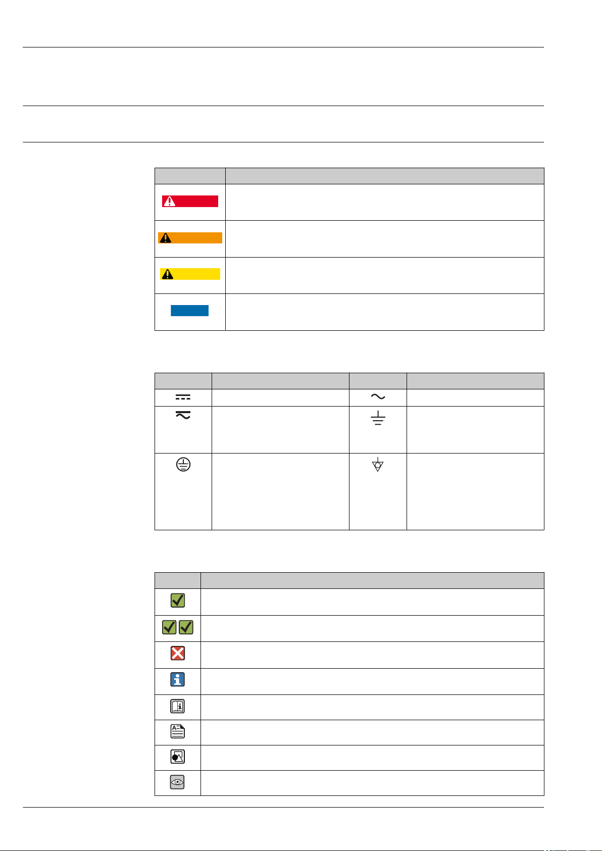
Symbols used Safety symbols
Symbol Meaning
Electrical symbols
Symbol Meaning Symbol Meaning
DANGER!
This symbol alerts you to a dangerous situation. Failure to avoid this situation will result in
serious or fatal injury.
WARNING!
This symbol alerts you to a dangerous situation. Failure to avoid this situation can result in
serious or fatal injury.
CAUTION!
This symbol alerts you to a dangerous situation. Failure to avoid this situation can result in
minor or medium injury.
NOTE!
This symbol contains information on procedures and other facts which do not result in
personal injury.
Direct current Alternating current
Direct current and alternating current Ground connection
Protective ground connection
A terminal which must be connected
to ground prior to establishing any
other connections.
Symbols for certain types of information
Symbol Meaning
Permitted
Procedures, processes or actions that are permitted.
Preferred
Procedures, processes or actions that are preferred.
Forbidden
Procedures, processes or actions that are forbidden.
Tip
Indicates additional information.
Reference to documentation
A grounded terminal which, as far as
the operator is concerned, is
grounded via a grounding system.
Equipotential connection
A connection that has to be connected
to the plant grounding system: This
may be a potential equalization line
or a star grounding system depending
on national or company codes of
practice.
Reference to page
Reference to graphic
Visual inspection
4 Endress+Hauser
Page 5
Waterpilot FMX21
,…,
Symbols in graphics
Symbol Meaning
1, 2, 3 ... Item numbers
Series of steps
A, B, C, ... Views
A-A, B-B, C-C, ... Sections
Supplementary documentation
The document types listed are available:
In the Download Area of the Endress+Hauser Internet site: www.endress.com → Download
Brief Operating Instructions (KA): getting the 1st measured value quickly
FMX21 4 to 20 mA Analog - KA01244P:
FMX21 4 to 20 mA HART - KA01189P:
The Brief Operating Instructions contain all the essential information from incoming acceptance to
initial commissioning.
Operating Instructions (BA): your comprehensive reference
FMX21 4 to 20 mA Analog - BA01605P:
FMX21 4 to 20 mA HART - BA00380P:
RIA15 - BA01170K:
These Operating Instructions contain all the information that is required in various phases of the life
cycle of the device: from product identification, incoming acceptance and storage, to mounting,
connection, operation and commissioning through to troubleshooting, maintenance and disposal.
Safety Instructions (XA)
Depending on the approval, the following Safety Instructions (XA) are supplied with the device. They
are an integral part of the Operating Instructions.
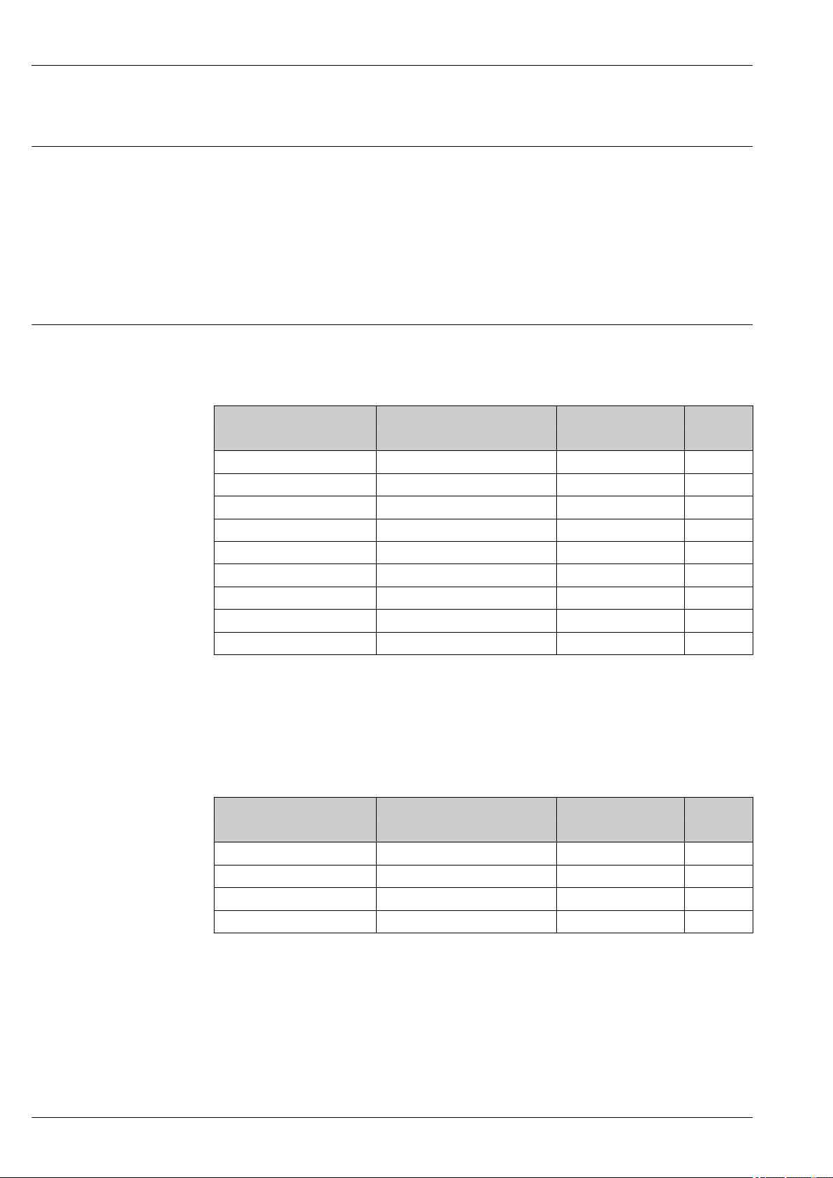
Directive Type of protection Category Documentation Option
ATEX Ex ia IIC II 2 G XA00454P BD
ATEX Ex nA IIC II 3 G XA00485P BE
IECEx Ex ia IIC n/a XA00455P IC
CSA C/US Ex ia IIC n/a ZD00232P
(960008976)
FM AEx ia IIC n/a ZD00231P
(960008975)
NEPSI Ex ia IIC n/a XA00456P NA
INMETRO Ex ia IIC n/a XA01066P MA
1)
CE
FE
1) Product Configurator order code for "Approval"
The nameplate indicates the Safety Instructions (XA) that are relevant to the device.
Endress+Hauser 5
Page 6
Terms and abbreviations
URL OPLMWP
LRL
0
p
LRV
URV
1
2
3
4
Waterpilot FMX21
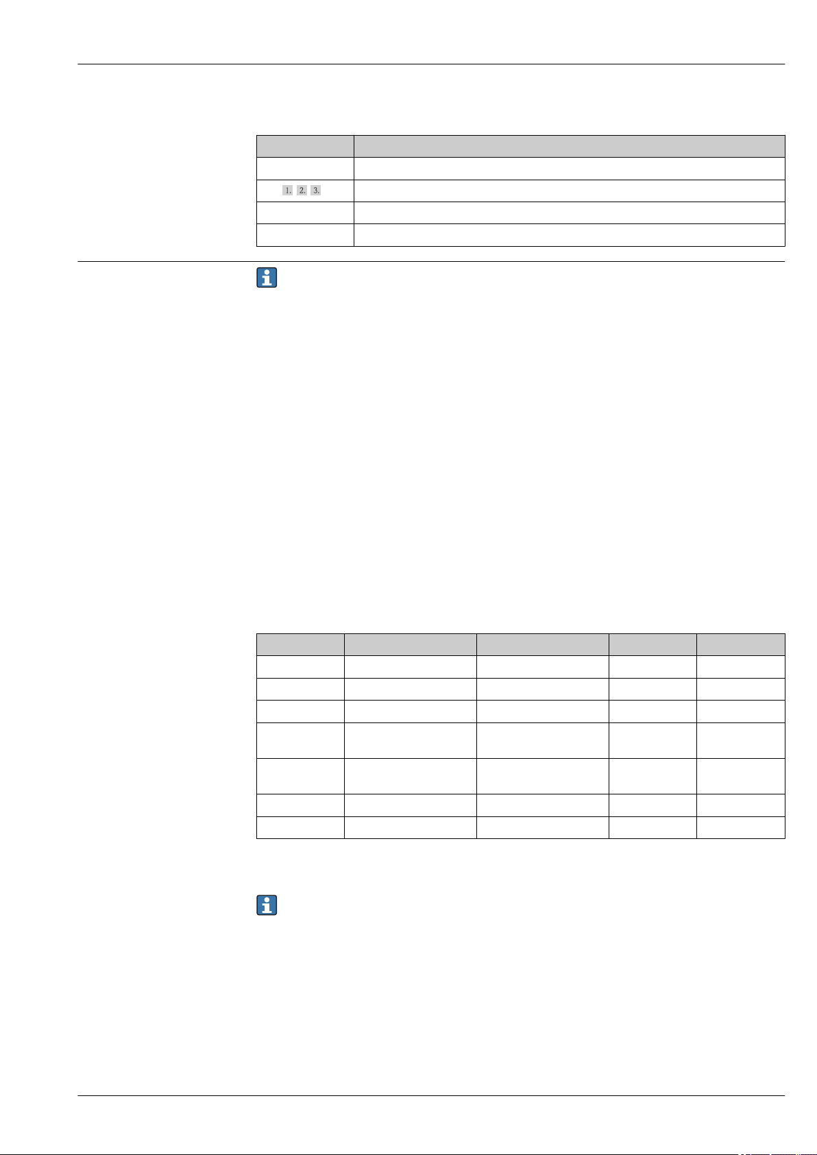
Item Term/abbreviation Explanation
1 OPL The OPL (over pressure limit = sensor overload limit) for the measuring device depends on the lowest-rated
element, with regard to pressure, of the selected components, i.e. the process connection has to be taken into
consideration in addition to the measuring cell. Also observe pressure-temperature dependency.
The OPL may only be applied for a limited period of time.
2 MWP The MWP (maximum working pressure) for the sensors depends on the lowest-rated element, with regard to
pressure, of the selected components, i.e. the process connection has to be taken into consideration in addition to
the measuring cell. Also observe pressure-temperature dependency.
The MWP may be applied at the device for an unlimited period.
The MWP can also be found on the nameplate.
3 Maximum sensor
measuring range
4 Calibrated/adjusted span Span between LRV and URV
p - Pressure
- LRL Lower range limit
- URL Upper range limit
- LRV Lower range value
- URV Upper range value
- TD (turn down) Turn down
- PE Polyethylene
- FEP Fluorinated ethylene propylene
- PUR Polyurethane
Span between LRL and URL
This sensor measuring range is equivalent to the maximum calibratable/adjustable span.
Factory setting: 0 to URL
Other calibrated spans can be ordered as customized spans.
Example - see the following section.
A0029505
6 Endress+Hauser
Page 7

Waterpilot FMX21
LRV
URLURV
LRL
1 = 2
3
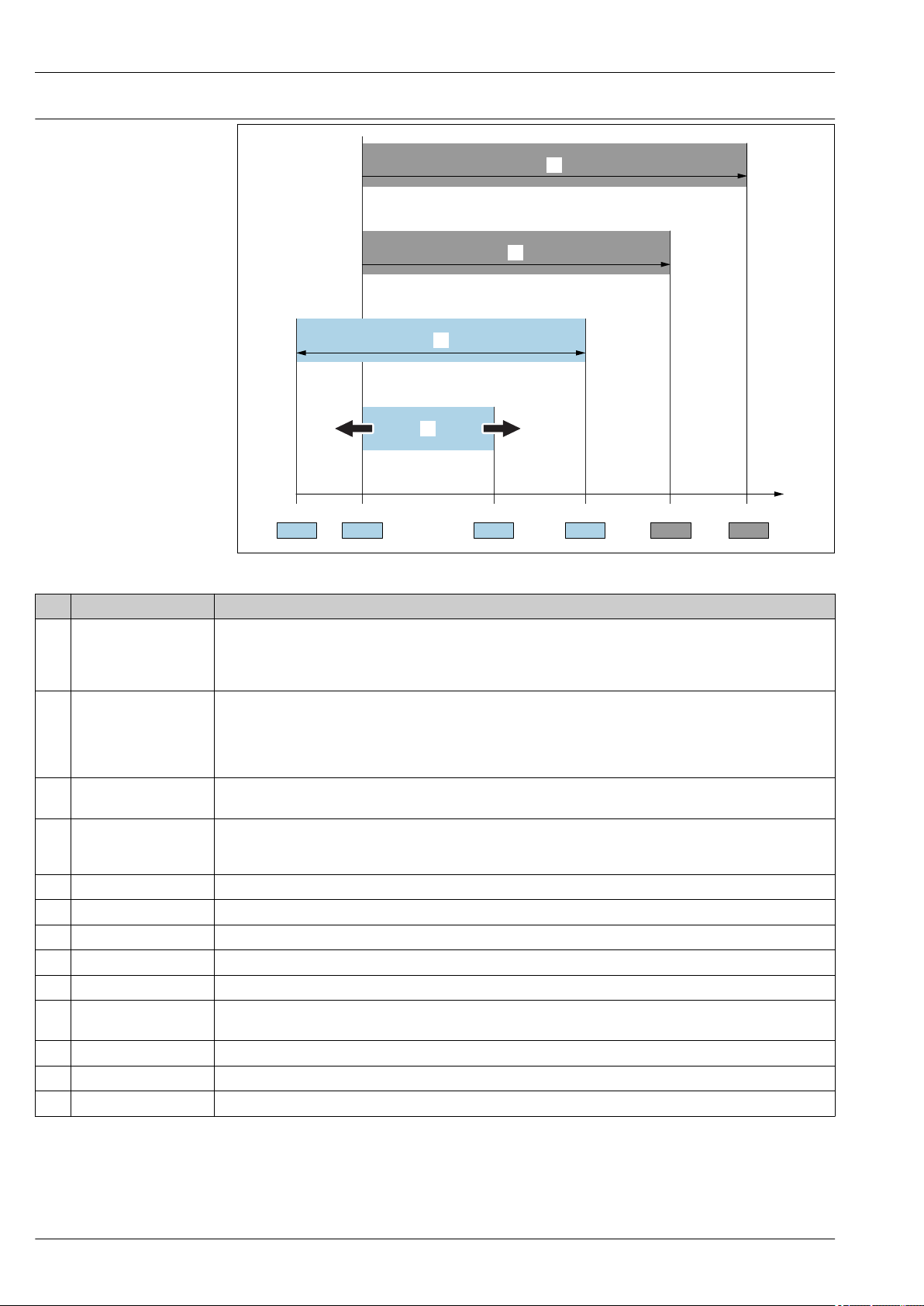
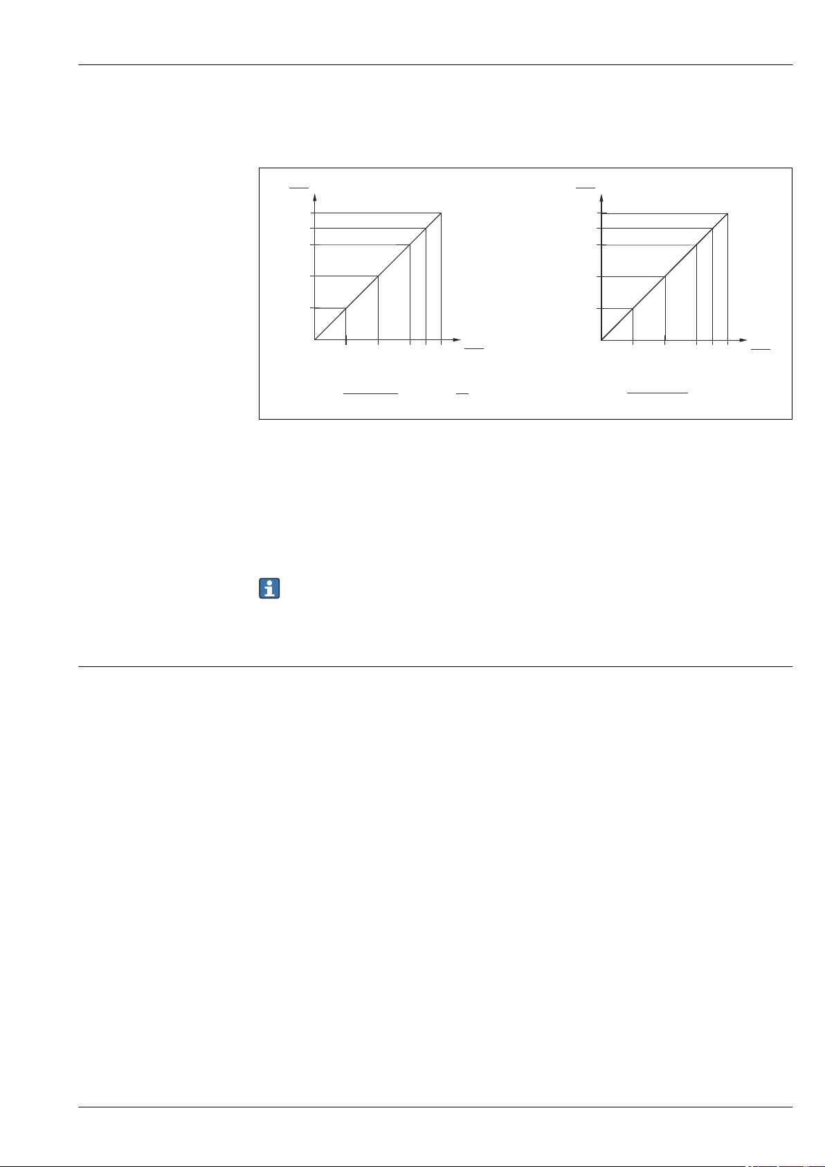
Turn down calculation
1 Calibrated/adjusted span
2 Zero point-based span (4 to 20 mA Analog: customer-specific span can only be set at the factory when
ordered)
3 URL sensor
Example
• Sensor:10 bar (150 psi)
• Upper range value (URL) = 10 bar (150 psi)
Turn down (TD):
• Calibrated/adjusted span: 0 to 5 bar (0 to 75 psi)
• Lower range value (LRV) = 0 bar (0 psi)
• Upper range value (URV) = 5 bar (75 psi)
A0029545
TD =
URL
|URV - LRV|
10 bar (150 psi)
TD =
|5 bar (75 psi) - 0 bar (0 psi)|
In this example, the TD is 2:1.
This span is based on the zero point.
= 2
Endress+Hauser 7
Page 8
Function and system design
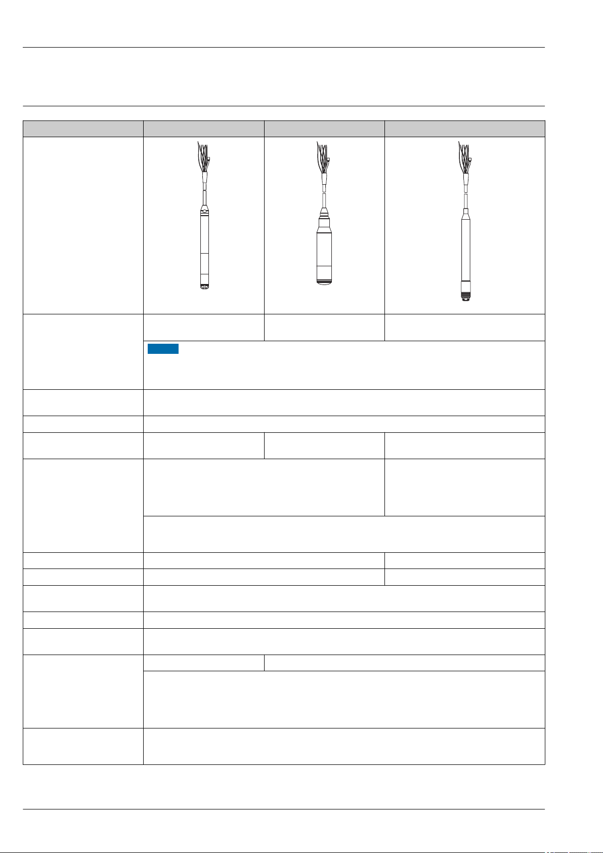
Device version
Outer diameter 22 mm (0.87 in) 42 mm (1.65 in) Max. 29 mm (1.14 in)
Waterpilot FMX21
A0018640
Field of application Hydrostatic level measurement
in deep wells e.g. drinking water
Hydrostatic level measurement
in wastewater
A0018641
Hydrostatic level measurement in saltwater
NOTICE
The Waterpilot is not suitable for use in biogas plants since the gases can diffuse through the elastomers
(seals, cable).
For applications involving biogas, Endress+Hauser offers the Deltapilot level measuring device.
‣
Process connection • Suspension clamp
• Cable mounting screw with G 1½" A or NPT 1½" thread
Extension cable PE, PUR, FEP → 45
Seals • FKM Viton
• EPDM
1)
Measuring ranges • Relative pressure: 0 to 0.1 bar (0 to 1.5 psi) to
0 to 20 bar (0 to 300 psi)
• Absolute pressure: 0 to 2 bar (0 to 30 psi) to
0 to 20 bar (0 to 300 psi)
FKM Viton • FKM Viton
• EPDM
1)
• Relative pressure:
0 to 0.1 bar (0 to 1.5 psi) to
0 to 4 bar (0 to 60 psi)
• Absolute pressure: 0 to 2 bar (0 to 30 psi)
to 0 to 4 bar (0 to 60 psi)
• Customer-specific measuring ranges; factory-calibrated.
• The following output units can be configured: %, mbar, bar, kPa, MPa, mmH2O, mH2O, inH2O, ftH2O, psi and
numerous level units.
Overload to 40 bar (600 psi) to 25 bar (375 psi)
Process temperature range –10 to +70 °C (+14 to +158 °F) 0 to +50 °C (+32 to +122 °F)
Reference accuracy • ±0.2 % of the set span
• Optional: ±0.1 % of set span (PLATINUM version)
Supply voltage 10.5 to 35 V DC, Ex: 10.5 to 30 V DC
Output • 4 to 20 mA Analog
• 4 to 20 mA HART (can be inverted) with superimposed digital communication protocol HART 6.0, 2-wire
Options Drinking water approval ―
• Wide range of approvals, including ATEX, FM, CSA
• Numerous accessories
• Integrated Pt100 temperature sensor and TMT181 temperature head transmitter (4 to 20 mA)
• Integrated Pt100 temperature sensor and TMT182 temperature head transmitter (4 to 20 mA HART)
• Marine approval
Specialties • High-precision, robust ceramic measuring cell with long-term stability
• Automatic density compensation
• Customer-specific cable marking
A0018642
1) Recommended for drinking water applications, not suitable for use in hazardous areas.
8 Endress+Hauser
Page 9
Waterpilot FMX21
h
2
1
p
atm
p
hydr.
p = p + p
atm hydr.
p
atm
p
atm
h ~ p
r • g
h =
p
Rel.: p = (p + p ) - p
sens atm hydr. atm
p = p + p
atm hydr.
Abs.: p = (p + p )
sens atm hydr.
Measuring principle
The ceramic measuring cell is a dry measuring cell i.e. the pressure acts directly on the robust,
ceramic process isolating diaphragm of the Waterpilot FMX21. Changes in air pressure are guided
via a pressure compensation tube through the extension cable to the rear of the ceramic process
isolating diaphragm and are compensated for. A pressure-dependent change in capacitance, caused
by the movement of the process isolating diaphragm, is measured at the electrodes of the ceramic
carrier. The electronics unit then converts this to a signal that is proportional to the pressure and
linear to the level.
1 Ceramic measuring cell
2 Pressure compensation tube
h Height level
p Total pressure = atmospheric pressure + hydrostatic pressure
ρ Density of the medium
g Acceleration due to gravity
P
Hydrostatic pressure
hydr.
P
Atmospheric pressure
atm
P
Pressure displayed on the sensor
sens
Temperature measurement with optional Pt100 resistance thermometer
1)
For simultaneous measurement of level and temperature, Endress+Hauser offers the Waterpilot
FMX21 with an optional 4-wire Pt100 resistance thermometer → 52. The Pt100 is categorized
as Accuracy Class B as per DIN EN 60751.
Temperature measurement with optional Pt100 and TMT181 temperature head transmitter
for FMX21 4 to 20 mA Analog
To convert the temperature signal to an analog, scalable 4 to 20 mA output signal, Endress+Hauser
also offers the TMT181 temperature head transmitter.
1)
Ordering information: → 50; "Accessories" → 52. Technical Information TI00070R.
Temperature measurement with optional Pt100 and TMT182 temperature head transmitter
for FMX21 4 to 20 mA HART
1)
Endress+Hauser also offers the TMT182 temperature head transmitter with HART protocol for
converting the temperature signal to an analog, scalable 4 to 20 mA output signal superimposed
with HART 6.0. See also: "Density compensation with Pt100 temperature sensor" → 12
Ordering information: → 50; "Accessories" → 52. Technical Information TI00078R.
A0019140
1) Not for use in hazardous areas.
Endress+Hauser 9
Page 10
Measuring system Application examples
A
B
C
D
5
5
5
5
2
1
4
4
4
4
RN221N
RTA421
RIA45RIA15
ON
1
2
E
-+-
RIA45
RIA452
Memograph M
Ecograph T
RIA452
Endress+Hauser
%
RIA46
12401.5
E
-+-
ON
1
2
3
3
3
3
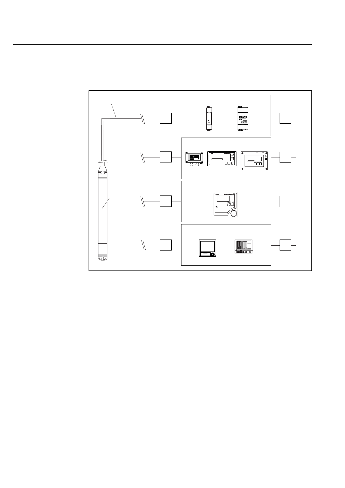
As standard, the complete measuring system consists of a Waterpilot FMX21 and a transmitter
power supply unit with a supply voltage of 10.5 to 30 V DC (hazardous areas) or 10.5 to 35 V DC
(non-hazardous areas).
Possible measuring point solutions with a transmitter and evaluation units from Endress+Hauser:
Waterpilot FMX21
A0018644
1 Waterpilot FMX21
2 4 to 20 mA or 4 to 20 mA HART
3+4 Overvoltage protection, e.g. HAW from Endress+Hauser (not for use in hazardous areas) HAW562; for DIN
rail: HAW562/intrinsically safe HAW562Z. Selection in accordance with supply voltage.
5 Power supply
A: Easy and cost-effective measuring point solution: power supplied to the Waterpilot in hazardous
and non-hazardous areas via the RN221N active barrier. Power supply and additional control of two
appliances, such as pumps, via the RTA421 limit value switch with local display.
B: The RIA45 evaluation unit (for panel mounting) or the RIA46 evaluation unit (for field
installation) offers power supply, local display and two switch outputs. If the RIA15 is used, the basic
settings for the FMX21 HART can be made via the display module.
C: If several pumps are used, the pump service life can be prolonged by alternate switching. With
alternating pump control, the pump which was out of service for the longest period of time is
switched on. The RIA452 evaluation unit (for panel mounting) offers this option in addition to
numerous other functions.
D: State-of-the-art recording technology with graphic display recorders from Endress+Hauser, such
as Ecograph T, Memograph M for documentation, monitoring, visualization and archiving purposes.
10 Endress+Hauser
Page 11
Waterpilot FMX21
RIA452
ENDRESS+HAUSER
RMA422
RMA42
E
F
RIA46
RIA45
12401.5
E
-+-
ON
1
2
ON
1
2
E
-+-
RIA45
ON
1
2
E
-+-
RIA45
ON
1
2
E
-+-
RIA45
ON
1
2
E
-+-
RIA45
RIA45
2
3
4
3
4
5
5
5
5
6
6
6
7
7
7
1
2
RIA452
Endress+Hauser
%
ENDRESS+HAUSER
RMA422
RMA42
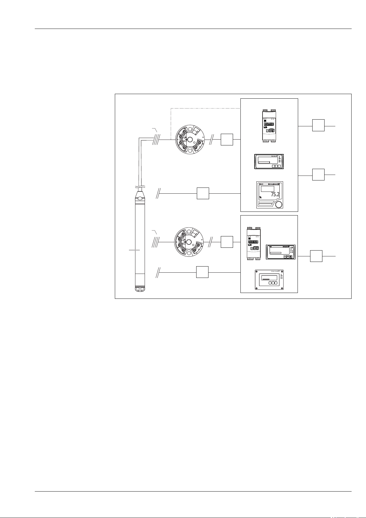
Application examples with the Pt100
As standard, the complete measuring system consists of a Waterpilot FMX21 and a transmitter
power supply unit with a supply voltage of 10.5 to 30 V DC (hazardous areas) or 10.5 to 35 V DC
(non-hazardous areas).
Possible measuring point solutions with a transmitter and evaluation units from Endress+Hauser:
A0018645
1 Waterpilot FMX21
2 Connection for integrated Pt100 in the FMX21
3 Temperature for 4 to 20 mA or 4 to 20 mA HART
4 Level for 4 to 20 mA or 4 to 20 mA HART
5 Overvoltage protection, e.g. HAW from Endress+Hauser (not for use in hazardous areas) on the sensor side
6 Overvoltage protection, e.g. HAW from Endress+Hauser (not for use in hazardous areas) on the supply side
7 Power supply
E: If you wish to measure, display and evaluate the temperature as well as the level, e.g. to monitor
the temperature in fresh water for the purpose of detecting temperature limits for germ formation,
the options available to you include the following: The optionally available TMT182 temperature
head transmitter can convert the Pt100 signal to a 4 to 20 mA signal or a 4 to 20 mA HART signal
and transfer it to any commonly used evaluation unit. The RMA42, RIA45 and RIA452 evaluation
units also offer a direct input for the Pt100 signal.
for field installation: HAW569; for DIN rail: HAW562/intrinsically safe HAW562Z. Selection in accordance
with supply voltage.
for DIN rail: HAW561 (115/230 V) and HAW561K (24/48 V AC/DC). Selection in accordance with supply
voltage.
F: If you wish to record and evaluate the level and temperature measured value with one device, use
the RMA42, RIA45 and RIA46 evaluation units with two inputs. It is even possible to mathematically
Endress+Hauser 11
link the input signals with this unit. These evaluation units are HART-compatible.
Page 12
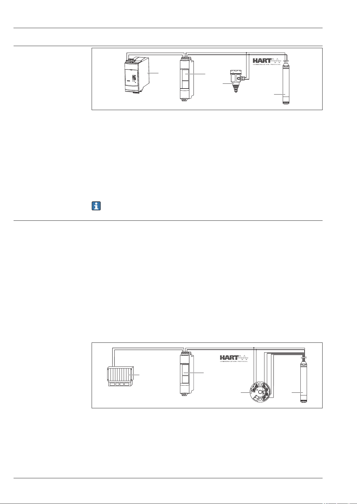
Level measurement with
FXN520
1
2
3
4
1
2
3
4
FXN520
absolute pressure probe and
external pressure signal for
FMX21 4 to 20 mA HART
Waterpilot FMX21
A0018757
1 Fieldgate FXA520
2 Multidrop Connector FXN520
3 Cerabar
4 Waterpilot FMX21 4 to 20 mA HART
It is advisable to use an absolute pressure probe for applications in which condensation can occur.
For level measurement using an absolute pressure probe, the measured value is affected by
fluctuations in the ambient pressure. To correct the resulting measured error, you can connect an
external absolute pressure sensor (e.g. Cerabar) to the HART signal line, switch the Waterpilot to
burst mode and operate the Cerabar in the "Electr. Delta P" mode. The external absolute pressure
sensor then calculates the difference between the two pressure signals and can thus determine the
level precisely. Only one level measured value can be corrected in this way.
If using intrinsically safe devices, the regulations for interconnecting intrinsically safe circuits as
stipulated in IEC60079-14 (proof of intrinsic safety) must be observed.
Density compensation with the Pt100 temperature sensor for FMX21 4 to 20 mA HART
The Waterpilot FMX21 4 to 20 mA HART can correct measured errors that result from fluctuations
in the density of the water caused by temperature. Users can choose from the following options:
Use the internally measured sensor temperature of the FMX21
The internally measured sensor temperature is calculated in the Waterpilot FMX21 4 to 20 mA
HART for density compensation. The level signal is thus corrected according to the density
characteristic line of water.
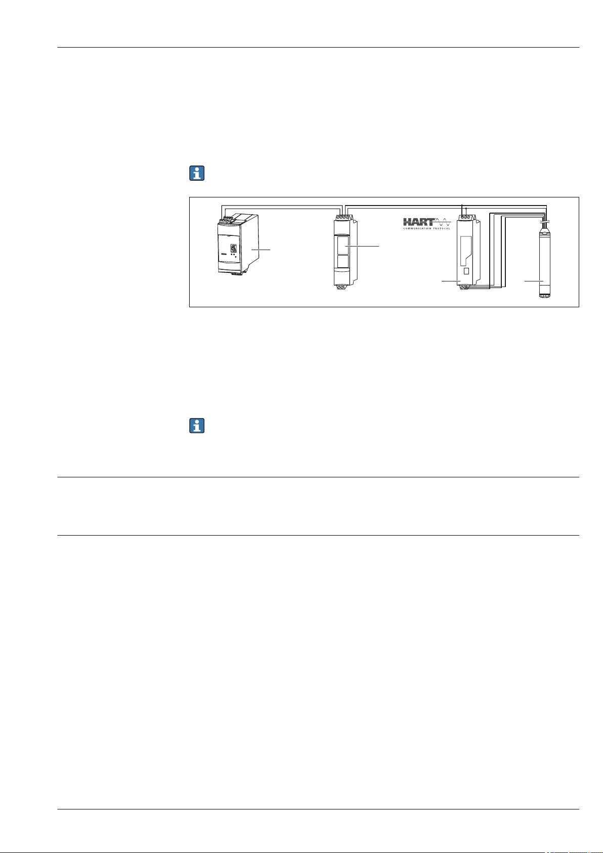
Use the optional internal temperature sensor for density compensation in a suitable HART
master (e.g. PLC)
The Waterpilot FMX21 4 to 20 mA HART is optionally available with a Pt100 temperature sensor.
To convert the Pt100 signal to a 4 to 20 mA HART signal, Endress+Hauser also offers the TMT182
temperature head transmitter.
The temperature and pressure signals are queried by a HART master (e.g. PLC), where a corrected
level value can be generated using a stored linearization table or density function (of a chosen
medium).
A0018763
1 HART master, e.g. PLC (programmable logic controller)
2 FXN520 Multidrop Connector
3 TMT182 temperature head transmitter
4 Waterpilot FMX21 4 to 20 mA HART
12 Endress+Hauser
Page 13
Waterpilot FMX21
FXN520
4
1
2
3
Use an external temperature signal, which is transmitted to the FMX21 4 to 20 mA HART via
the HART burst mode
The Waterpilot FMX21 4 to 20 mA HART is optionally available with a Pt100 temperature sensor.
With this option, the signal of the Pt100 is evaluated with a HART-compliant temperature
transmitter (min. HART 5.0) that supports the BURST mode. The temperature signal can thus be
transmitted to the FMX21 4 to 20 mA HART. The FMX21 4 to 20 mA HART uses this signal for
density correction of the level signal.
The TMT182 temperature head transmitter is not suitable for this configuration.
A0018764
1 Fieldgate FXA520
2 Multidrop Connector FXN520
3 HART-compatible temperature transmitter (e.g. TMT82)
4 Waterpilot FMX21 4 to 20 mA HART
Communication protocol
System integration
Without additional compensation due to the anomaly of water, errors of up to 4% may occur at a
temperature of 70 °C (158 °F), for example. With density compensation, this error can be decreased
to 0.5 % in the entire temperature range from 0 to +70 °C (+32 to +158 °F).
More information can be found in the Technical Information:
• TI01010T: TMT82 temperature transmitter (4 to 20 mA HART)
• TI00369F: Fieldgate FXA520
• TI00400F: Multidrop Connector FXN520
• 4 to 20 mA Analog
Ordering information: Product Configurator order code for "Output", option "1"
• 4...20 mA HART
Ordering information: Product Configurator order code for "Output", option "2"
The device can be given a tag name.
Ordering information: Product Configurator order code for "Identification", option "Z1"
Endress+Hauser 13
Page 14
Input
Measured variable FMX21 + Pt100 (optional)
• Hydrostatic pressure of a liquid
• Pt100: Temperature
TMT181 temperature head transmitter (optional) for FMX21 4 to 20 mA Analog
Temperature
TMT182 temperature head transmitter (optional) for FMX21 4 to 20 mA HART
Temperature
Waterpilot FMX21
Measuring range
• Customer-specific measuring ranges or calibration that has been preset in the factory
• Temperature measurement of –10 to +70 °C (+14 to +158 °F) with Pt100 (optional)
Relative pressure
Sensor measuring range Lowest calibratable span
[bar (psi)] [bar (psi)] [bar
1)
Vacuum resistance Option
(psi
abs
)]
abs
0.1 (1.5) 0.01 (0.15) 0.3 (4.5) 1C
0.2 (3.0) 0.02 (0.3) 0.3 (4.5) 1D
0.4 (6.0) 0.04 (1.0) 0 1F
0.6 (9.0) 0.06 (1.0) 0 1G
1.0 (15.0) 0.1 (1.5) 0 1H
2.0 (30.0) 0.2 (3.0) 0 1K
4.0 (60.0) 0.4 (6.0) 0 1M
10.0 (150)
20.0 (300)
3)
3)
1.0 (15) 0 1P
2.0 (30) 0 1Q
1) Largest turn down that can be configured at the factory: 10:1, higher turn down can be configured on
request or in the device (for FMX21 4 to 20 mA HART).
2) Product Configurator order code for "Sensor range"
3) These measuring ranges are not available for the special version with plastic insulation, external diameter
of 29 mm (1.14 in).
2)
Absolute pressure
Sensor measuring range Lowest calibratable span
[bar (psi)] [bar (psi)] [bar
1)
Vacuum resistance Option
(psi
abs
)]
abs
2.0 (30.0) 0.2 (3.0) 0 2K
4.0 (60.0) 0.4 (6.0) 0 2M
10.0 (150)
20.0 (300)
3)
3)
1.0 (15) 0 2P
2.0 (30) 0 2Q
1) Largest turn down that can be configured at the factory: 10:1, higher turn down can be configured on
request or in the device (for FMX21 4 to 20 mA HART).
2) Product Configurator order code for "Sensor range"
3) These measuring ranges are not available for the special version with plastic insulation, external diameter
of 29 mm (1.14 in).
2)
14 Endress+Hauser
Page 15

Waterpilot FMX21
Input signal FMX21 + Pt100 (optional)
• Change in capacitance
• Pt100: Change in resistance
TMT181 temperature head transmitter (optional) for FMX21 4 to 20 mA Analog
Pt100 resistance signal, 4 wire
TMT182 temperature head transmitter (optional) for FMX21 4 to 20 mA HART
Pt100 resistance signal, 4 wire
Endress+Hauser 15
Page 16
Output
R
Lmax
– 2 0.09•
• L – R
U – 10.5 V
23 mA
W
m
£
413
630
195
1065
35
20
25
10.5
15
847
30
R
[ ]W
U
[ ]
V
– R
U – 8 V
0.025 A
£
R
Lmax
A
B
30
20 25158
35
10
1080
880
480
280
680
80
R
[ ]W
U
[ ]
V
add
add
Output signal FMX21 + Pt100 (optional)
• 4 to 20 mA Analog, 2-wire for hydrostatic pressure measured value.
Ordering information: Product Configurator order code for "Output", option "1"
• 4 to 20 mA HART with superimposed digital communication protocol HART 6.0, 2-wire for
hydrostatic pressure measured value.
Ordering information: Product Configurator order code for "Output", option "2"
Options:
– Max. alarm (factory setting 22mA): can be set from 21 to 23 mA
– Hold measured value: last measured value is held
– Min. alarm: 3.6 mA
• Pt100: temperature-dependent resistance value
TMT181 temperature head transmitter (optional) for FMX21 4 to 20 mA Analog
4 to 20 mA Analog for temperature measured value, 2-wire
TMT182 temperature head transmitter (optional) for FMX21 4 to 20 mA HART
4 to 20 mA HART with superimposed digital communication protocol HART 5.0 for temperature
measured value, 2-wire
Waterpilot FMX21
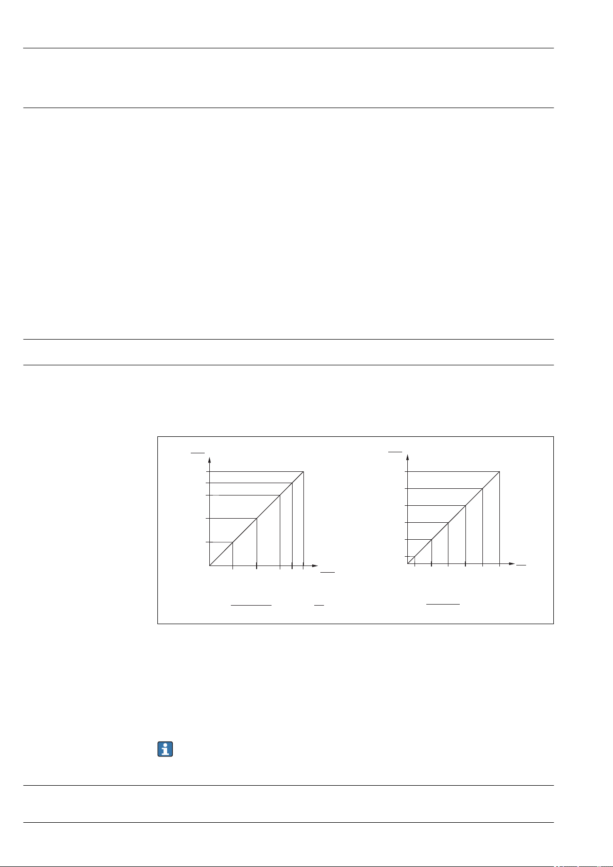
Signal range
Maximum load for FMX21 4 to 20 mA Analog
3.8 mA to 20.5 mA
The maximum load resistance depends on the supply voltage (U) and must be determined
individually for each current loop, see formula and diagrams for FMX21 and temperature head
transmitter. The total resistance resulting from the resistances of the connected devices, the
connecting cable and, where applicable, the resistance of the extension cable may not exceed the
load resistance value.
A FMX21 4 to 20 mA Analog load chart for estimating the load resistance. Additional resistances, such as the
resistance of the extension cable, have to be subtracted from the value calculated as shown in the equation.
B Load diagram for TMT181 temperature head transmitter for estimating the load resistance. Additional
resistances must be subtracted from the value calculated as shown in the equation
R
Max. load resistance [Ω]
Lmax
R
Additional resistances such as resistance of evaluating device and/or display unit, cable resistance [Ω]
add
U Supply voltage [V]
L Basic length of extension cable [m] (cable resistance per wire 0.09 Ω/m)
Maximum load for FMX21 4 to 20 mA HART
16 Endress+Hauser
The maximum load resistance depends on the supply voltage (U) and must be determined
individually for each current loop, see formula and diagrams for FMX21 and temperature head
When using the measuring device in hazardous areas, installation must comply with the
corresponding national standards and regulations and the Safety Instructions or Installation or
Control Drawings (XA).
A0030561-EN
Page 17
Waterpilot FMX21
R
Lmax
– 2 0.09•
• L – R
U – 10.5 V
23 mA
W
m
£
413
630
195
1065
35
20
25
10.5
15
847
30
R
[ ]W
U
[ ]
V
– R
U – 11.5 V
0.023 A
£
R
Lmax
370
587
152
1022
35
20
25
11.5
15
804
30
R
[ ]W
U
[ ]
V
A B
add add
transmitter. The total resistance resulting from the resistances of the connected devices, the
connecting cable and, where applicable, the resistance of the extension cable may not exceed the
load resistance value.
A0026500-EN
A FMX21 4 to 20 mA HART load chart for estimating the load resistance. Additional resistances, such as the
resistance of the extension cable, have to be subtracted from the value calculated as shown in the equation.
B Load diagram for TMT182 temperature head transmitter for estimating the load resistance. Additional
resistances must be subtracted from the value calculated as shown in the equation
R
Max. load resistance [Ω]
Lmax
R
Additional resistances such as resistance of evaluating device and/or display unit, cable resistance [Ω]
add
U Supply voltage [V]
L Basic length of extension cable [m] (cable resistance per wire 0.09 Ω/m)
• When using the measuring device in hazardous areas, installation must comply with the
corresponding national standards and regulations and the Safety Instructions or Installation
or Control Drawings (XA).
• When operating via a handheld terminal or via a PC with an operating program, a minimum
communication resistance of 250 Ω must be taken into account.
Damping for FMX21 4 to 20 mA HART
• Via HART handheld device or PC with operating program: continuous from 0 to 999 s
• Factory setting: 2 s
Endress+Hauser 17
Page 18

Waterpilot FMX21
Protocol-specific data for FMX21 4 to 20 mA HART
Manufacturer ID 17 (11 hex)
Device type code 25 (19 hex)
Device revision 01 (01 hex) - SW version 01.00.zz
HART specification 6
DD revision 01
Device description files
(DTM, DD)
HART load Min. 250 Ω
HART device variables The dynamic variables SV, TV and QV may be assigned to any device variable:
Supported functions • Burst mode
Information and files under:
• www.endress.com
• www.fieldcommgroup.org
Standard process values for SV, TV (second and third device variable) are
dependent on the measuring mode:
• Pressure
• Level
Standard process value for QV (fourth device variable) is the sensor
temperature:
Temperature
Measured values for PV (first device variable) are dependent on the measuring
mode:
• Pressure
• Level
• Tank content
• Additional transmitter status
• Device locking
• Alternative measuring modes
• Catch variable
• Long tag
18 Endress+Hauser
Page 19

Waterpilot FMX21
Power supply
WARNING
L
Electrical safety is compromised by an incorrect connection!
When using the measuring device in a hazardous area, the relevant national standards and
‣
guidelines as well as the Safety Instructions (XAs) or installation or control drawings (ZDs) must
be adhered to. All data relating to explosion protection can be found in separate documentation
which is available on request. This documentation is supplied with the devices as standard
→ 5
Supply voltage FMX21 + Pt100 (optional)
• 10.5 to 35 V (not hazardous areas)
• 10.5 to 30 V (hazardous areas)
TMT181 temperature head transmitter (optional) for FMX21 4 to 20 mA Analog
8 to 35 V DC
TMT182 temperature head transmitter (optional) for FMX21 4 to 20 mA HART
11.5 to 35 V DC
Power consumption FMX21 + Pt100 (optional)
• ≤ 0.805 W at 35 V DC (non-hazardous area)
• ≤ 0.690 W at 30 V DC (hazardous area)
TMT181 temperature head transmitter (optional) for FMX21 4 to 20 mA Analog
≤ 0.875 W at 35 V DC
TMT182 temperature head transmitter (optional) for FMX21 4 to 20 mA HART
≤ 0.805 W at 35 V DC
Current consumption FMX21 + Pt100 (optional)
Max. current consumption: ≤ 23 mA
Min. current consumption: ≥ 3.6 mA
TMT181 temperature head transmitter (optional) for FMX21 4 to 20 mA Analog
• Max. current consumption: ≤ 25 mA
• Min. current consumption: ≥ 3.5 mA
TMT182 temperature head transmitter (optional) for FMX21 4 to 20 mA HART
• Max. current consumption: ≤ 23 mA
• Min. current consumption: ≥ 3.5 mA
Connecting the device
• Waterpilot
Reverse polarity protection is integrated in the Waterpilot FMX21 and the temperature head
transmitter. Changing the polarities will not result in damage to the devices.
• The cable must end in a dry room or a suitable terminal box. The terminal box (IP66/IP67) with
GORE-TEX® filter from Endress+Hauser is suitable for outdoor installation. The terminal box may
be ordered as an accessory using the order code for the FMX21, Product Configurator order code
for "Accessories enclosed", option "PS".
The electrical connection is established with the corresponding wires of the probe cable and with the
optional use of the terminal box → 37 and a power supply (e.g. RN221N active barrier
→ 10).
Endress+Hauser 19
Page 20

Waterpilot FMX21
RD
BK
RD
BK
WH
YE BU
BR
a
A B
e
)
)
)
)
c
c
d
d
b
b
a
FMX21
FMX21
RD BKWHYE
BU
BR
)
)
a
b
c
f
d
cd
g
6
5
4
3
2
1
e
FMX21 4...20 mA Analog
Waterpilot with Pt100
A0019441
A Waterpilot FMX21
B Waterpilot FMX21 with Pt100 (not for use in hazardous areas); option "NB", Product Configurator order code
for "Accessories"
a Not for the FMX21 with external diameter of 29 mm (1.14 in)
b 10.5 to 30 V DC (hazardous area), 10.5 to 35 V DC
c 4...20 mA
d Resistance (RL)
e Pt100
Waterpilot with Pt100 and TMT181 temperature head transmitter for
FMX21 4 to 20 mA Analog
a Not for the FMX21 with external diameter of 29 mm (1.14 in)
b 10.5 to 35 V DC
c 4...20 mA
d Resistance (RL)
e TMT181 temperature head transmitter (4 to 20 mA) (not for use in hazardous areas)
f 8 to 35 V DC
g Pt100
1...6 Pin assignment
20 Endress+Hauser
Ordering information:
Pt100: Product Configurator order code for "Accessories mounted", option "NB"
A0030945
Page 21

Waterpilot FMX21
)
a
b
c
e
f
d
cd
g
RD BKWHYE
BU
BR
2
1
6
5
4
3
)
FMX21 4...20 mA HART
TMT181: Product Configurator order code for "Accessories enclosed", option "PX"
Waterpilot with Pt100 and TMT182 temperature head transmitter for
FMX21 4 to 20 mA HART
A0018780
a Not for the FMX21 with external diameter of 29 mm (1.14 in)
b 10.5 to 35 V DC
c 4...20 mA
d Resistance (RL)
e TMT182 temperature head transmitter (4 to 20 mA) (not for use in hazardous areas)
f 11.5 to 35 V DC
g Pt100
1...6 Pin assignment
Ordering information:
Pt100: Product Configurator order code for "Accessories mounted", option "NB"
TMT182: Product Configurator order code for "Accessories enclosed", option "PT"
Endress+Hauser 21
Page 22

Waterpilot FMX21
Y
I
R
s
DC
1
2
3
LED
-
+
Y
I
R
s
DC
1
2
3
LED
-
+
Waterpilot FMX21 with RIA15
The RIA15 remote display can be ordered together with the device.
Product structure, feature 620 "Accessory enclosed":
• Option R4 "Remote display RIA15 non-hazardous area, field housing"
• Option R5 "Remote display RIA15 Ex= explosion protection approval, field housing"
Compensation of the atmospheric pressure must be ensured for the installation. A black, vented
cable gland is supplied for this purpose.
The RIA15 process display unit is loop-powered and does not require any external power
supply.
The voltage drop to be taken into account is:
• ≤1 V in the standard version with 4 to 20 mA communication
• ≤1.9 V with HART communication
• and an additional 2.9 V if display light is used
Circuit diagram / Description
Waterpilot FMX21 connection, HART
communication and RIA15 without
backlight
Waterpilot FMX21 connection, HART
communication and RIA15 with
backlight
A0019567
1 Waterpilot FMX21 block diagram, HART with RIA15 process
display unit without light
1 Waterpilot FMX21
2 Power supply
3 HART resistance
A0019568
2 Waterpilot FMX21 block diagram, HART with RIA15 process
display unit with light
1 Waterpilot FMX21
2 Power supply
3 HART resistance
22 Endress+Hauser
Page 23

Waterpilot FMX21
1
LED
-
+
3
2
Y
I
R
s
DC
1
3
2
Y
I
R
s
DC
LED
-
+
Waterpilot FMX21, RIA15 with installed HART communication resistor module
The HART communication module for installation in the RIA15 can be ordered together with
the device.
Product structure, feature 620 "Accessory enclosed":
• Option R6 "HART communication resistor hazardous / non-hazardous area"
• The voltage drop to be taken into account is max. 7 V
Compensation of the atmospheric pressure must be ensured for the installation. A black, vented
cable gland is supplied for this purpose.
Circuit diagram / Description
Waterpilot FMX21 connection and
RIA15 without backlight
A0020839
3 Waterpilot FMX21 block diagram, RIA15 without light, HART
communication resistor module
1 HART communication resistor module
2 Waterpilot FMX21
3 Power supply
Waterpilot FMX21 connection and
RIA15 with backlight
A0020840
4 Waterpilot FMX21 block diagram, RIA15 with light, HART
communication resistor module
1 HART communication resistor module
2 Waterpilot FMX21
3 Power supply
Wire colors
RD = red, BK = black, WH = white, YE = yellow, BU = blue, BR = brown
Connection data
Connection classification as per IEC 61010-1:
• Overvoltage category 1
• Pollution level 1
Connection data in the hazardous area
See relevant XA.
Terminals in the terminal box
• Three terminals as standard in the terminal box (terminal box can optionally be ordered as an
enclosed accessory → 52)
• 4-terminal strip can be ordered as an accessory, order number: 52008938 cable cross-section 0.08
to 2.5 mm2 (28 to 14 AWG)
The 4-terminal strip is not designed for use in hazardous areas incl. CSA GP.
Endress+Hauser 23
Page 24

Waterpilot FMX21
Probe cable
Cable resistance
Cable specifications
• Overall external diameter: 8 mm (0.31 in) ±0.25 mm (0.01 in)
• Pressure compensation tube with Teflon filter: External diameter of 2.5 mm (0.1 in), internal
diameter of 1.5 mm (0.06 in)
Cross-section
• FMX21: 3 x 0.2 mm2 (3 x 26 AWG) + pressure compensation tube with Teflon filter
• FMX21 with Pt100 (optional): 7 x 0.2 mm2 (7 x 26 AWG) + pressure compensation tube with
Teflon filter
per wire: ≤ 0.09 Ω/m
Endress+Hauser recommends using shielded, twisted-pair two-wire cables.
The probe cables are shielded for device versions with outer diameters of 22 mm (0.87 in) and
42 mm (1.65 in).
FMX21 + Pt100 (optional)
• Commercially available instrument cable
• Terminals, terminal box: 0.08 to 2.5 mm2 (28 to 14 AWG)
TMT181 temperature head transmitter (optional) for FMX21 4 to 20 mA Analog
• Commercially available instrument cable
• Terminals, terminal box: 0.08 to 2.5 mm2 (28 to 14 AWG)
• Transmitter connection: max. 1.75 mm2 (15 AWG)
TMT182 temperature head transmitter (optional) for FMX21 4 to 20 mA HART
• Commercially available instrument cable
• Terminals, terminal box: 0.08 to 2.5 mm2 (28 to 14 AWG)
• Transmitter connection: max. 1.75 mm2 (15 AWG)
Residual ripple for FMX21 4 to 20 mA Analog
Residual ripple for FMX21 4 to 20 mA HART
FMX21 + Pt100 (optional)
No impact on the 4 to 20 mA signal up to ±5 % residual ripple within the permitted voltage range.
TMT181 temperature head transmitter (optional)
Uss ≥ 5 V at U ≥ 13 V, f
max.
= 1 kHz
FMX21 + Pt100 (optional)
No impact on the 4 to 20 mA signal up to ±5 % residual ripple within the permitted voltage range
(according to HART Hardware Specification HCF_SPEC-54 (DIN IEC 60381-1)).
TMT182 temperature head transmitter (optional)
Uss ≥ 3 V at U ≥ 13 V, f
max.
= 1 kHz
24 Endress+Hauser
Page 25

Waterpilot FMX21
Performance characteristics
Reference operating conditions
Reference accuracy FMX21 + Pt100 (optional)
FMX21 + Pt100 (optional)
• As per IEC 60770
• Ambient temperature TU = constant, in the range of +21 to +33 °C (+70 to +91 °F)
• Humidity φ = constant, in the range of 20 to 80 % rH
• Ambient pressure pU = constant, in the range of 860 to 1 060 mbar (12.47 to 15.37 psi)
• Position of measuring cell constant, vertical in the range of ±1°
• Input of LOW SENSOR TRIM and HIGH SENSOR TRIM for lower range value and upper range value
(only for HART)
• Supply voltage constant: 21 V DC to 27 V DC
• Load with HART: 250 Ω
• Pt100: DIN EN 60770, TU = +25 °C (+77 °F)
TMT181 temperature head transmitter (optional) for FMX21 4 to 20 mA Analog
Calibration temperature +23 °C (+73 °F) ±5 K
TMT182 temperature head transmitter (optional) for FMX21 4 to 20 mA HART
Calibration temperature +25 °C (+77 °F) ±5 K
The reference accuracy comprises the non-linearity after limit point configuration, hysteresis and
non-reproducibility in accordance IEC 60770.
Standard version
Setting ±0.2 %
– to TD 5:1: < 0.2 % of set span
– from TD 5:1 to TD 20:1 ±(0.02 x TD+0.1)
Platinum version
• Setting ±0.1 % (optional)
– to TD 5:1: < 0.1 % of set span
– from TD 5:1 to TD 20:1 ±(0.02 x TD)
• Class B as per DIN EN 60751
Pt100: max. ±1 K
2)
:
3)
:
TMT181 temperature head transmitter (optional) for FMX21 4 to 20 mA Analog
• ±0.2 K
• With Pt100: max. ±0.9 K
TMT182 temperature head transmitter (optional) for FMX21 4 to 20 mA HART
• ±0.2 K
• With Pt100: max. ±0.9 K
Resolution
2) Ordering information: Product Configurator order code for "Reference accuracy", option "G"
3) Ordering information: Product Configurator order code for "Reference accuracy", option "D"
Current output: 1 μA
Reading cycle
HART commands: on average 2 to 3 per second
Endress+Hauser 25
Page 26

Long-term stability FMX21 + Pt100 (optional)
• ≤ 0.1 % of URL/year
• ≤ 0.25 % of URL/5 years
TMT181 temperature head transmitter (optional) for FMX21 4 to 20 mA Analog
≤ 0.1 K per year
TMT182 temperature head transmitter (optional) for FMX21 4 to 20 mA HART
≤ 0.1 K per year
Waterpilot FMX21
Influence of medium temperature
Warm-up period FMX21 + Pt100 (optional)
Response time FMX21 + Pt100 (optional)
• Thermal change in the zero output and the output span:
0 to +30 °C (+32 to +86 °F): < (0.15 + 0.15 x TD)% of set span
–10 to +70 °C (+14 to +158 °F): < (0.4 + 0.4 x TD)% of set span
• Temperature coefficient (TK) of the zero output and the output span
–10 to +70 °C (+14 to +158 °F): 0.1 % / 10 K of URL
• FMX21: < 6 s
• Pt100: 300 s
TMT181 temperature head transmitter (optional) for FMX21 4 to 20 mA Analog
4 s
TMT182 temperature head transmitter (optional) for FMX21 4 to 20 mA HART
4 s
• FMX21: 400 ms (T90 time), 500 ms (T99 time)
• Pt100: 160 s (T90 time), 300 s (T99 time)
26 Endress+Hauser
Page 27

Waterpilot FMX21
1
2
3
4
5
6
7
8
9
Dat./Insp.:
FW.Ver.: xxxx
Dev.Rev.: xxxx
Cal./Adj.
Mat:
L=
Ser. no.:xxxxxxxxxxxxx
Order code: xxxxxxxxxxxxxxxxxxxxxx
Ext. order code:xxxxxxxxxxxxxxxxxxxxxx
TAG:xxxxxxxxxxxxxxxxx
xxxxxxxxxxxxxxxxx
xxxxxxxxxxxxxxxxx
Waterpilot FMX21
Made in Germany,D-79689 Maulburg
p
Ex ia IICT6-T4
£
-10°C Ta 70°C
£
Ta 40°C forT6
£
Ta 70°C forT4
£
Ui 30VDC ; Ii 133mA; Pi 1W
£
£
£
II 2G
Ci= 5nF + 180pF/m ; Li= 1 µH/m
Warning!
Avoid electrostatic
charge
0...400mbar
4... 20 mA
0...600mbar
red
+
black
-
yellow-green
4…20 mA
Sensor
250002736--
10,5... 35VDC
XAxxxxxP-
XX/XXXX
TÜV 01ATEX 1685
PPS/Polyolefin
AL2O3
FEPEPDM
OPEN
CLOSE
90°
90°
Warning:
Avoid electrostatic charge in explosive atmosphere.
See instructions
Terminal Box for FMX21
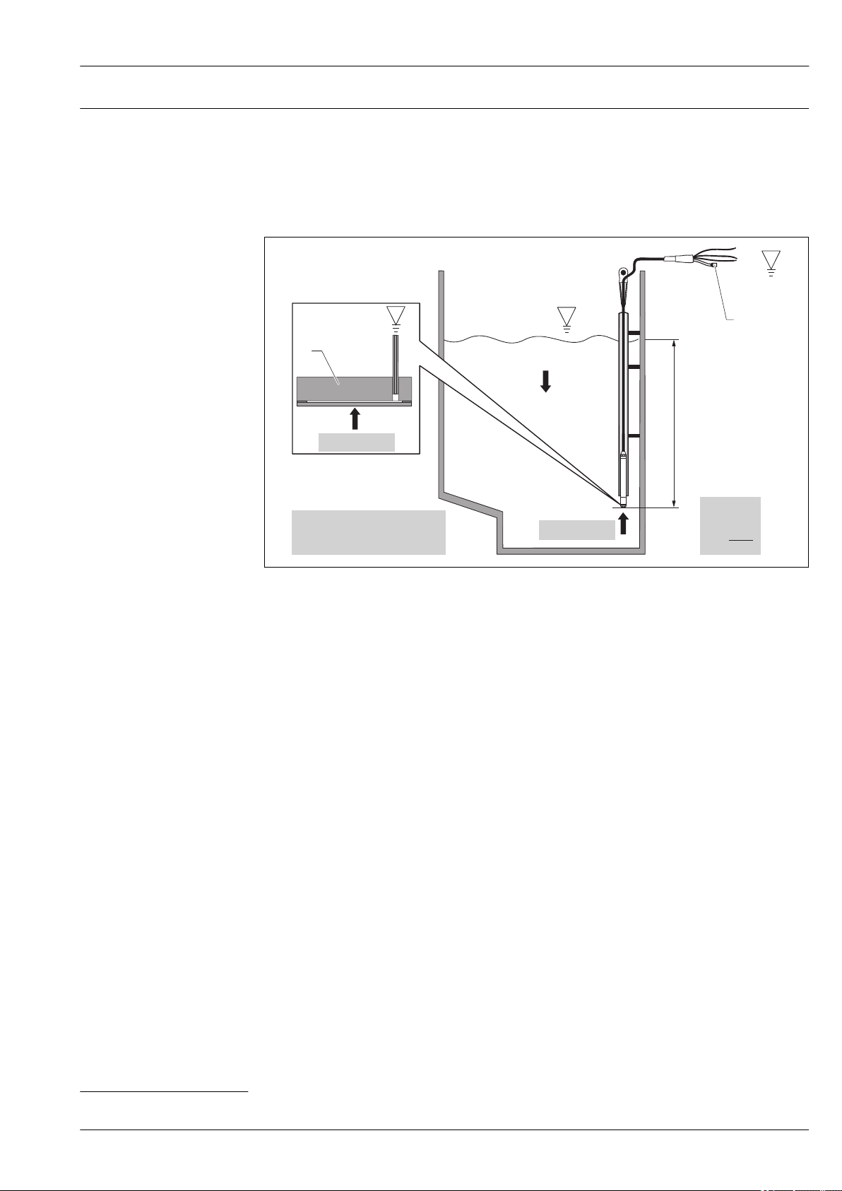
Installation instructions
Installation
A0018770
1 Cable mounting screw can be ordered via the order code or as an accessory → 52
2 Terminal box can be ordered via the order code or as an accessory → 52
3 Bending radius of extension cable > 120 mm (4.72 in)
4 Mounting clamp can be ordered via the order code or as an accessory → 52
5 Extension cable, cable length → 28
6 Guide tube
7 Waterpilot FMX21
8 Additional weight can be ordered as an accessory for the FMX21 with external diameter of 22 mm (0.87 in)
and 29 mm (1.14 in)→ 52
9 Protection cap
Additional installation instructions
• Sideways movement of the level probe can result in measuring errors. For this reason, install the
probe at a point free from flow and turbulence, or use a guide tube. The internal diameter of the
guide tube should be at least 1 mm (0.04 in) greater than the external diameter of the selected
FMX21.
• To avoid mechanical damage to the measuring cell, the device is equipped with a protection cap.
• The cable must end in a dry room or a suitable terminal box. The terminal box from Endress
+Hauser provides humidity and climatic protection and is suitable for installation outdoors
→ 52.
• Cable length tolerance: < 5 m (16 ft): ±17.5 mm (0.69 in); > 5 m (16 ft): ±0.2 %
• If the cable is shortened, the filter at the pressure compensation tube must be reattached. Endress
+Hauser offers a cable shortening kit for this purpose → 52 (documentation SD00552P/00/
A6).
Endress+Hauser 27
Page 28

Waterpilot FMX21
L
E
A
• Endress+Hauser recommends using twisted, shielded cable.
• In shipbuilding applications, measures are required to restrict the spread of fire along cable looms.
• The length of the extension cable depends on the intended level zero point. The height of the
protection cap must be taken into consideration when designing the layout of the measuring
point. The level zero point (E) corresponds to the position of the process isolating diaphragm.
Level zero point = E; tip of probe = L (see the following diagram).
For dimensions, see "Mechanical construction" section.
A0026013
Cable length
• Pay attention to the "Load"
• Cable lengths available for order
– Customer-specific in meters or feet
– Limited cable length when performing installation with freely suspended device with cable
mounting screw or mounting clamp, as well as for Ex approval: max. 300 m (984 ft).
When using the measuring device in hazardous areas, installation must comply with the
corresponding national standards and regulations and the Safety Instructions or Installation or
Control Drawings.
A Length of extension cable
Cable Option
10 m cable, can be shortened, PE 10
20 m cable, can be shortened, PE 11
..... m cable, can be shortened, PE 15
30 ft cable, can be shortened, PE 20
60 ft cable, can be shortened, PE 21
..... ft cable, can be shortened, PE 25
10 m cable, can be shortened, FEP 30
20 m cable, can be shortened, FEP 31
1)
28 Endress+Hauser
A0020556
Page 29

Waterpilot FMX21
Technical data for cable
Cable Option
..... m cable, can be shortened, FEP 35
30 ft cable, can be shortened, FEP 40
60 ft cable, can be shortened, FEP 41
..... ft cable, can be shortened, FEP 45
10 m cable, can be shortened, PUR 50
20 m cable, can be shortened, PUR 51
..... m cable, can be shortened, PUR 55
30 ft cable, can be shortened, PUR 60
60 ft cable, can be shortened, PUR 61
..... ft cable, can be shortened, PUR 65
1) Ordering information: Product Configurator order code for "Probe connection"
• Minimum bending radius: 120 mm (4.72 in)
• Tensile strength: max. 950 N (213.56 lbf)
• Cable extraction force (= tensile force required to extract the cable from the probe):
– PE, FEP: typically ≥ 400 N (89.92 lbf), PUR: typically ≥ 150 N (33.72 lbf)
– when used in hazardous area: ≥ 100 N (73.75 lbf)
• UV-resistant (UV = ultraviolet)
• PE: For use in drinking water
1)
Cable marking
A0030955
• To make installation easier, Endress+Hauser marks the extension cable if a customer-specific
length has been ordered.
Ordering information: Product Configurator order code for "Service", option "IR" or "IS".
• Cable marking tolerance (distance to lower end of level probe):
Cable length < 5 m (16 ft): ±17.5 mm (0.69 in)
Cable length > 5 m (16 ft): ±0.2 %
• Material: PET, stick-on label: acrylic
• Immunity to temperature change: –30 to +100 °C (–22 to +212 °F)
NOTICE
The marking is used exclusively for installation purposes.
The mark must be thoroughly removed without trace in the case of devices with drinking water
‣
approval. The extension cable must not be damaged in the process.
Not for use of the FMX21 in hazardous areas.
Endress+Hauser 29
Page 30

Cable shortening kit
Waterpilot FMX21
A0030948
The cable shortening kit is used to shorten a cable easily and professionally.
The cable shortening kit is not designed for the FMX21 with FM/CSA approval.
• Ordering information: Product Configurator order code for "Accessories enclosed", option "PW"
• Associated documentation SD00552P/00/A6.
30 Endress+Hauser
Page 31

Waterpilot FMX21
Environment
Ambient temperature range FMX21 + Pt100 (optional)
• With external diameter of 22 mm (0.87 in) and 42 mm (1.65 in):
–10 to +70 °C (+14 to +158 °F) (= medium temperature)
• With external diameter of29 mm (1.14 in):
0 to +50 °C (+32 to +122 °F) (= medium temperature)
Cable
(when mounted in a fixed position)
• With PE: –30 to +70 °C (–22 to +158 °F)
• With FEP: –40 to +70 °C (–40 to +158 °F)
• With PUR: –40 to +70 °C (–40 to +158 °F)
Terminal box
–40 to +80 °C (–40 to +176 °F)
TMT181 temperature head transmitter (optional) for FMX21 4 to 20 mA Analog
–40 to +85 °C (–40 to +185 °F)
Temperature head transmitter 2-wire, configured for a measuring range of
–20 to +80 °C (–4 to +176 °F). This configuration offers a temperature range of 100 K which can be
easily mapped. Please note that the Pt100 resistance temperature detector is suitable for a
temperature range of –10 to +70 °C (14 to +158 °F)
The TMT181 temperature head transmitter is not designed for use in hazardous areas incl. CSA
GP.
TMT182 temperature head transmitter (optional) for FMX21 4 to 20 mA HART
–40 to +85 °C (–40 to +185 °F)
Temperature head transmitter 2-wire, configured for a measuring range of
–20 to +80 °C (–4 to +176 °F). This configuration offers a temperature range of 100 K which can be
easily mapped. Please note that the Pt100 resistance temperature detector is suitable for a
temperature range of –10 to +70 °C (14 to +158 °F)
The TMT182 temperature head transmitter is not designed for use in hazardous areas incl. CSA
GP.
Storage temperature range FMX21 + Pt100 (optional)
–40 to +80 °C (–40 to +176 °F)
Cable
(when mounted in a fixed position)
• With PE: –30 to +70 °C (–22 to +158 °F)
• With FEP: –30 to +80 °C (–22 to +176 °F)
• With PUR: –40 to +80 °C (–40 to +176 °F)
Terminal box
–40 to +80 °C (–40 to +176 °F)
TMT181 temperature head transmitter (optional) for FMX21 4 to 20 mA Analog
–40 to +100 °C (–40 to +212 °F)
TMT182 temperature head transmitter (optional) for FMX21 4 to 20 mA HART
–40 to +100 °C (–40 to +212 °F)
Degree of protection FMX21 + Pt100 (optional)
IP68, permanently hermetically sealed at 20 bar (290 psi) (~200 m H2O)
Endress+Hauser 31
Page 32

Waterpilot FMX21
Terminal box (optional)
IP66, IP67
TMT181 temperature head transmitter (optional) for FMX21 4 to 20 mA Analog
IP00, condensation permitted
When installed in the optional terminal boxes: IP66/IP67
TMT182 temperature head transmitter (optional) for FMX21 4 to 20 mA HART
IP00, condensation permitted
Electromagnetic compatibility (EMC)
Overvoltage protection FMX21 + Pt100 (optional)
FMX21 + Pt100 (optional)
• EMC in accordance with all relevant requirements of EN 61326 series. For details, refer to the
Declaration of Conformity.
• Maximum deviation: < 0.5 % of span.
TMT181 temperature head transmitter (optional) for FMX21 4 to 20 mA Analog
Interference emission to EN 61326 Class B equipment, interference immunity to EN 61326
Appendix A (Industrial). For details, refer to the Declaration of Conformity.
TMT182 temperature head transmitter (optional) for FMX21 4 to 20 mA HART
EMC in accordance with all relevant requirements of EN 61326 series. For details, refer to the
Declaration of Conformity.
• Integrated overvoltage protection as per EN 61000-4-5 (500 V symmetrical/1000 V
asymmetrical)
• Overvoltage protection ≥ 1.0 kV, external if necessary
TMT181 temperature head transmitter (optional) for FMX21 4 to 20 mA Analog
Provide overvoltage protection, externally if necessary → 10.
TMT182 temperature head transmitter (optional) for FMX21 4 to 20 mA HART
Provide overvoltage protection, externally if necessary → 10.
32 Endress+Hauser
Page 33

Waterpilot FMX21
Process
Medium temperature range FMX21 + Pt100 (optional)
• With external diameter of 22 mm (0.87 in) and 42 mm (1.65 in):
–10 to +70 °C (+14 to +158 °F)
• With external diameter of 29 mm (1.14 in):
0 to +50 °C (+32 to +122 °F)
TMT181 temperature head transmitter (optional) for FMX21 4 to 20 mA Analog
–40 to +85 °C (–40 to +185 °F)
(= ambient temperature), install temperature head transmitter outside the medium.
Temperature head transmitter 2-wire, configured for a measuring range of
–20 to +80 °C (–4 to +176 °F). This configuration offers a temperature range of 100 K which can be
easily mapped. Please note that the Pt100 resistance temperature detector is suitable for a
temperature range of –10 to +70 °C (14 to +158 °F)
The TMT181 temperature head transmitter is not designed for use in hazardous areas incl. CSA
GP.
TMT181 temperature head transmitter (optional) for FMX21 4 to 20 mA HART
–40 to +85 °C (–40 to +185 °F)
(= ambient temperature), install temperature head transmitter outside the medium.
Temperature head transmitter 2-wire, configured for a measuring range of
–20 to +80 °C (–4 to +176 °F). This configuration offers a temperature range of 100 K which can be
easily mapped. Please note that the Pt100 resistance temperature detector is suitable for a
temperature range of –10 to +70 °C (14 to +158 °F)
The TMT182 temperature head transmitter is not designed for use in hazardous areas incl. CSA
GP.
Medium temperature limit FMX21 + Pt100 (optional)
With external diameter of 22 mm (0.87 in) and 42 mm (1.65 in):
–20 to +70 °C (–4 to +158 °F)
In hazardous areas incl. CSA GP, the medium temperature limit is
–10 to +70 °C (+14 to +158 °F).
With external diameter of29 mm (1.14 in): 0 to +50 °C (+32 to +122 °F)
The FMX21 may be operated in this temperature range. The specification values, such as
accuracy, may be exceeded.
Endress+Hauser 33
Page 34

Waterpilot FMX21
Pressure specifications
WARNING
L
The maximum pressure for the measuring device depends on the lowest-rated element with
regard to pressure.
For pressure specifications, see the "Measuring range" section and the "Mechanical construction"
‣
section.
The measuring device must be operated only within the specified limits!
‣
The Pressure Equipment Directive (2014/68/EU) uses the abbreviation "PS". The abbreviation "PS"
‣
corresponds to the MWP (maximum working pressure) of the measuring device.
MWP (maximum working pressure): The MWP (maximum working pressure) is specified on the
‣
nameplate. This value refers to a reference temperature of +20 °C (+68 °F) and may be applied to
the device for an unlimited time. Observe temperature dependency of the MWP.
OPL (Over Pressure Limit = sensor overload limit): The test pressure corresponds to the over
‣
pressure limit of the sensor and may only be applied for a limited time period to ensure
measurement within specification and in order to avoid permanent damage. In the case of sensor
range and process connections where the over pressure limit (OPL) of the process connection is
smaller than the nominal value of the sensor, the device is set at the factory, at the very
maximum, to the OPL value of the process connection. If you want to use the entire sensor range,
select a process connection with a higher OPL value.
avoid steam hammering! Steam hammering can cause zero point drifts. Recommendation:
‣
Residue (such as condensation or drops of water) can remain on the process isolating diaphragm
after CIP cleaning and lead to local steam hammering if steam cleaning is performed again. In
practice, drying the process isolating diaphragm (e.g. by blowing) has proved to prevent steam
hammering.
34 Endress+Hauser
Page 35

Waterpilot FMX21
249 (9.80)
259 (10.2)
ø22 (0.87) ±0.1
247
232
258
268
ø29≤ (1.14)
ø8 (0.31)
(9.13)
(9.72)
(10.6)
(10.2)
ø8 (0.31)
ø8 (0.31)
1
2
3 3 3
1
2
1
2
A B C
ø42 (1.65)
27 (1.06)
18 (0.71)
18 (0.71)
ø42.5 (1.67)
Dimensions of the level probe
Mechanical construction
A Product Configurator order code for "Probe tube", option "1" or "Accessories"
B Product Configurator order code for "Probe tube", option "2"
C Product Configurator order code for "Probe tube", option "5"
1 Pressure compensation tube
2 Extension cable (length, see → 28
3 Protection cap
Engineering unit mm (in)
A0018771
Endress+Hauser 35
Page 36

Dimensions of the mounting
48... 52 (2.0)
≤
22 (0.87)
175 (6.89)
52 (2.05)
NPT 1½"
ø55 (2.17)
G 1½ A"
~53 (2.1)
A B
~71 (2.8)
36
~71 (2.8)
41
clamp
Dimensions of cable mounting screw
Waterpilot FMX21
A0018659
Engineering unit mm (in)
Ordering information: Product Configurator order code for "Accessories", option "PO" → 52
A G 1½" A: Product Configurator order code for "Accessories", option "PQ" → 52
B NPT 1½": Product Configurator order code for "Accessories", option "PR" → 52
Engineering unit mm (in)
Use only in unpressurized vessels.
A0018661
36 Endress+Hauser
Page 37

Waterpilot FMX21
55 (2.17)
120 (4.72)
60 (2.36)0.5±
1
80 (3.15)
OPEN
CLOSE
90°
90°
ø4.5 (0.18)
50.2
(1.98)
10 (0.39)
108.2 (4.26)
~30
(1.18)
Warning:
Avoid electrostatic charge in explosive atmosphere.
See instructions
2
5
Terminal Box for FMX21
3
4
Dimensions of terminal box IP66, IP67 with filter
A0018772
1 Dummy plug M20x1.5
2 Cable gland M20x1.5
3
4 to 20 mA; terminals for 0.08 to 2.5 mm (28 to 14 AWG)0.08 to.2.5 mm
4
Ground connection; terminals for 0.08 to 2.5 mm (28 to 14 AWG)0.08 to 2.5 mm
2
2
5 GORE-TEX® filter
Engineering unit mm (in)
Terminal box IP66/IP67 with GORE-TEX® filter incl. 3 integrated terminals. The terminal box is also
suitable for the installation of a temperature head transmitter or four other terminals
Ordering information:
• Terminal box: Product Configurator order code for "Accessories enclosed", option "PS" → 52
• TMT181: Product Configurator order code for "Accessories enclosed", option "PX" → 52
• TMT182: Product Configurator order code for "Accessories enclosed", option "PT" → 52
The terminal box is not designed for the FMX21 with type of protection Ex nA in hazardous
areas. If the terminal box is used in a hazardous area, the Safety Instructions of the relevant
device must be observed, as well as the applicable regulations for explosion protection.
If the FMX21 with optional Pt100 is supplied, a terminal strip is provided with the terminal box for
the purpose of wiring the Pt100.
The 4-terminal strip is not designed for use in hazardous areas incl. CSA GP.
Endress+Hauser 37
Page 38

Dimensions of the TMT181
33 (1.30)
ø44 (1.73)
21 (0.83)
3
4
5
3
6
1
2
ø5 (ø0.19)
ø7 (0.27)
33 (1.30)
ø44 (1.73)
21 (0.83)
3
4
5
3
6
1
2
ø5 (ø0.19)
ø7 (0.27)
temperature head
transmitter for
FMX21 4 to 20 mA Analog
Dimensions of the TMT182 temperature head transmitter for FMX21 4 to 20 mA HART
Waterpilot FMX21
A0018775
Engineering unit mm (in)
Ordering information:
Product Configurator order code for "Accessories enclosed", option "PX" → 52
Engineering unit mm (in)
Ordering information:
Product Configurator order code for "Accessories enclosed", option "PT" → 52
A0018775
38 Endress+Hauser
Page 39

Waterpilot FMX21
>7 (0.28)1 2 3
>7 (0.28)1 2 3
Terminal box with integrated TMT181 temperature head transmitter for FMX21 4 to 20 mA Analog
A0018696
1 Terminal box
2 Terminal strip/terminals
3 TMT181 temperature head transmitter
Engineering unit mm (in)
A distance of > 7 mm (0.28 in) must be maintained between the terminal strip and the
TMT181 temperature head transmitter.
Terminal box with integrated TMT182 temperature head transmitter for FMX21 4 to 20 mA HART
A0018696
1 Terminal box
2 Terminal strip/terminals
3 TMT182 temperature head transmitter
Engineering unit mm (in)
A distance of > 7 mm (0.28 in) must be maintained between the terminal strip and the
TMT182 temperature head transmitter.
Endress+Hauser 39
Page 40

Additional weight For FMX21 with external diameter of 22 mm (0.87 in) or 29 mm (1.14 in)
ø22 (0.87)
M14x1
105.8 (4.16)
110.6 (4.35)
M14x1
~33 (1.3)
~25 (0.98)
1
2
22
13
12
• Endress+Hauser offers additional weights to prevent sideways movement that results in
measuring errors, or to make it easier to lower the device in a guide tube. You can screw several
weights together. The weights are screwed directly onto the FMX21. For the FMX21 with external
diameter of 29 mm (1.14 in), a maximum of 5 weights may be screwed on. In conjunction with the
Ex nA approval, a maximum of one additional weight is permitted for the FMX21 with external
diameter of 29 mm (1.14 in).
• Order number: 52006153 Ordering information: Product Configurator order code for "Accessories
enclosed", option "PU"
Waterpilot FMX21
Engineering unit mm (in)
Testing adapter For FMX21 with external diameter of 22 mm (0.87 in) or 29 mm (1.14 in)
• Endress+Hauser offers a testing adapter to ease function-testing of the level probes.
• Observe the maximum pressure for compressed air hose and maximum overload for level probe
→ 14
• Maximum pressure for the quick coupling piece provided: 10 bar (145 psi)
• Adapter material: 304 (1.4301)
• Material of quick coupling piece: anodized aluminum
• Order number 52011868
Ordering information: Product Configurator order code for "Accessories enclosed", option "PV"
1 FMX21 level probe connection
2 Compressed air hose connection, internal diameter, quick coupling piece 4 mm (0.16 in)
Engineering unit mm (in)
A0018748
A0018749
40 Endress+Hauser
Page 41

Waterpilot FMX21
131 (5.16) 55.5 (2.19)
106.5 (4.19)
81.5 (3.21)
mm (in)
54 (2.13)
31 (1.22)
24 (0.94)
22 (0.87)
8.1 (0.32)
RIA15 in the field housing
A0017722
5 Dimensions of RIA15 in field housing, engineering unit: mm (in)
The RIA15 remote display can be ordered together with the device. Product structure,
feature 620 "Accessories enclosed":
• Option R4 "Remote display RIA15 non-hazardous area, field housing"
• Option R5 "Remote display RIA15 Ex= explosion protection approval, field housing"
Alternatively available as an accessory, for details see Technical Information TI01043K and
Operating Instructions BA01170K
HART communication resistor
A0020858
6 Dimensions of HART communication resistor, engineering unit: mm (in)
A communication resistor is required for HART communication. If this is not already present
(e.g. in the power supply RMA, RN221N, RNS221, ...), it can be ordered with the device via the
product structure, feature 620 "Accessories enclosed": option R6 "HART communication resistor
hazardous / non-hazardous area".
Alternatively available as an accessory, for details see Technical Information TI01043K and
Operating Instructions BA01170K
The HART communication resistor is specially designed for use with the RIA15 and can be attached
easily.
Endress+Hauser 41
A0020844
Page 42

Waterpilot FMX21
1. Disconnect plug-in terminal block.
2. Insert the terminal block into the slot provided on the HART communication resistor module.
3. Insert the HART communication resistor in the slot in the housing.
Weight
Component part Weight
Level probe, external diameter of 22 mm (0.87 in) 344 g (12.133 oz)
Level probe, external diameter of 42 mm (1.65 in) 1 376 g (48.532 oz)
Level probe, external diameter of 29 mm (1.14 in) 394 g (13.896 oz)
Extension cable PE 52 g/m (0.035 lbs/1 ft)
PUR 60 g/m (0.040 lbs/1 ft)
FEP 108 g/m (0.072 lbs/1 ft)
Suspension clamp 170 g (5.996 oz)
Cable mounting screw G 1½" A 770 g (27.158 oz)
Cable mounting screw NPT 1½" 724 g (25.535 oz)
Terminal box 235 g (8.288 oz)
TMT181 temperature head transmitter 40 g (1.411 oz)
TMT182 temperature head transmitter 40 g (1.411 oz)
Additional weight 300 g (10.581 oz)
Testing adapter 39 g (1.376 oz)
42 Endress+Hauser
Page 43

Waterpilot FMX21
B
6
7
5
1
2
3
4
A
C
6
7
6
7
1
1
2
2
4
5
5
3
3
4
1.1
1.2
Materials
A0018787
Materials in contact with process
Item number Component part Material
1 • A: Level probe, external diameter of 22 mm (0.87 in)
• B: Level probe, external diameter of 42 mm (1.65 in)
• C: Level probe, max. external diameter of 29 mm (1.14 in)
1.1 Sensor sleeve PPS (Polyphenylene sulfide)
1.2 Heat-shrink tube Polyolefin and hot melt adhesive
The heat-shrink tube around the level probe acts as insulation. It prevents electrical contact between the level probe and the
tank. Electrochemical corrosion is thus avoided.
2 Protection cap for A and C: with outer diameter 22 mm (0.87 in) and
29 mm (1.14 in) (order number: 52008999)
Protection cap for B: device with outer diameter 42 mm (1.65 in) (order number:
917755-0000)
3 Process ceramic Al2O3 (Aluminum oxide ceramic)
4 Seal EPDM
5 Extension cable insulation
Additional information
316L (1.4404/1.4435)
POM
PFA
2)
FKM Viton
Choose from:
• PE-LD (Low-density polyethylene)
• FEP (Fluorinated ethylene propylene)
• PUR (Polyurethane)
3)
1)
1) Material 316L (1.4404/1.4435) is not in contact with the process in the case of level probe C
2) Product Configurator order code for "Seal", option "H"
3) Product Configurator order code for "Seal", option "A"
Materials not in contact with process
Item number Component part Material
6 Pressure compensation tube PA
7 Heat-shrink tube Polyolefin
Endress+Hauser 43
Page 44

Waterpilot FMX21
1
2
3
4
56
7
8
9
1
2
3 4
5
Terminal box (not in contact with process)
Item number Component part Material
1 Housing PC
2 Mounting screws (4 x) A2
3 Seal CR (Chloroprene rubber)
4 Dummy plug M20x1.5 PBT-GF30
5 Cable gland M20x1.5 PE-HD
6 PA6
7 PA6-GF30
8 Pressure compensation filter PA6-GF10, ePTFE
9 Pressure compensation filter, O-ring Silicone (VMQ)
A0018917
Cable mounting screw (not in contact with process)
Item number Component part Material
1 Cover for cable mounting screw 304 (1.4301)
2 Sealing ring NBR
3 Clamping sleeves PA66-GF35
4 Adapter for cable mounting screw G 1½" A, NPT 1½" 304 (1.4301)
5 Seal ® Only for G 1½" A EPDM
Suspension clamp
A0018918
Material: 316L (1.4404) and fiber-glass reinforced PA (polyamide)
44 Endress+Hauser
A0030950
Page 45

Waterpilot FMX21
Additional weight
A0030954
Material: 316L (1.4435)
Testing adapter for FMX21 with outer diameter 22 mm (0.87 in) or 29 mm (1.14 in)
Adapter material: 304 (1.4301)
Material of quick coupling piece: anodized aluminum
Testing adapter for FMX21 with outer diameter 42 mm (1.65 in)
Adapter material: 304 (1.4301)
Material of quick coupling piece: anodized aluminum
A0030956
A0030957
Extension cable
PE PUR FEP
• Abrasion-resistant extension cable with strainrelief members made of high-strength PE fibers
• Shielded (aluminum)
• Insulated with polyethylene (PE), black
• Copper wires, twisted
• Pressure compensation tube with Teflon filter
• Abrasion-resistant extension cable with strainrelief members made of high-strength PE fibers
• Shielded (aluminum)
• Insulated with polyurethane (PUR), black
• Copper wires, twisted
• Pressure compensation tube with Teflon filter
• Abrasion-resistant extension cable
• Shielded with galvanized steel wire netting
• Insulated with fluorinated ethylene
propylene (FEP), black
• Copper wires, twisted
• Pressure compensation tube with Teflon
filter
Endress+Hauser 45
Page 46

Operability
Waterpilot FMX21
FMX21 4 to 20 mA Analog
FMX21 4 to 20 mA HART FieldCare
No display or other operation facility is required to operate the device. However, the measured values
can be read out with optional evaluation units.
FieldCare is an Endress+Hauser asset management tool based on FDT technology. With FieldCare,
you can configure all Endress+Hauser devices as well as devices from other manufacturers that
support the FDT standard.
FieldCare supports the following functions:
• Configuration of transmitters in online and offline mode
• Loading and saving device data (upload/download)
• Documentation of the measuring point
Connection options:
• Via Commubox FXA195 and the USB interface of a computer
• Via Fieldgate FXA520
For additional information and free download of FieldCare, see → www.de.endress.com → Download
→ Text Search: FieldCare
DeviceCare
Function scope
Tool for connecting and configuring Endress+Hauser field devices.
The fastest way to configure Endress+Hauser field devices is with the dedicated "DeviceCare" tool.
Together with the device type managers (DTMs) it presents a convenient, comprehensive solution.
For details, see Innovation brochure IN01047S
RIA15
Field Xpert SFX
Field Xpert SFX is an industrial PDA with integrated 3.5" touchscreen from Endress+Hauser based on
Windows Mobile. It offers wireless communication via the optional VIATOR® Bluetooth ® modem as
a point-to-point connection to a HART device, or via WiFi and Endress+Hauser’s Fieldgate FXA520
to one or more HART devices. Field Xpert also works as a stand-alone device for asset management
applications. For details, refer to BA00060S/04/EN.
The RIA15 can be used as a local display unit and for the basic commissioning of the Waterpilot
FMX21 hydrostatic level sensor via HART.
46 Endress+Hauser
Page 47

Waterpilot FMX21
Certificates and approvals
CE mark
RCM-Tick marking
Ex approvals
The device meets the legal requirements of the relevant EC directives. Endress+Hauser confirms that
the device has been successfully tested by applying the CE mark.
The supplied product or measuring system meets the ACMA (Australian Communications and Media
Authority) requirements for network integrity, interoperability, performance characteristics as well
as health and safety regulations. Here, especially the regulatory arrangements for electromagnetic
compatibility are met. The products are labelled with the RCM- Tick marking on the name plate.
A0029561
• ATEX
• CSA C/US
• FM
• IEC
• NEPSI
• INMETRO
• The approvals apply exclusively to the Waterpilot FMX21 without Pt100 and without
TMT181/TMT182.
• Waterpilot FMX21 is only available for use in hazardous areas with the FKM Viton seal.
• All explosion protection data are given in separate documentation which is available upon
request. The Ex documentation is supplied as standard with all Ex-systems → 5.
EAC conformity
Drinking water approval
Marine approval
The measuring system meets the legal requirements of the applicable EAC guidelines. These are
listed in the corresponding EAC Declaration of Conformity together with the standards applied.
Endress+Hauser confirms successful testing of the device by affixing to it the EAC mark.
For FMX21 with an external diameter of 22 mm (0.87 in) with EPDM seal
Designation Option
KTW LQ
NSF61 LR
ACS LS
1) Product Configurator order code for "Additional ordering information (optional)"
1)
For FMX21 with outer diameter 22 mm (0.87 in).
Designation Option
GL LE
ABS LF
BV LH
DNV LI
1) Product Configurator order code for "Additional ordering information (optional)"
1)
Endress+Hauser 47
Page 48

Waterpilot FMX21
Other standards and guidelines
The applicable European guidelines and standards can be found in the relevant EU Declarations of
Conformity. The following were also applied:
DIN EN 60770 (IEC 60770):
Transmitters for use in industrial process control systems Part 1: Methods for performance
evaluation
Methods for evaluating the performance of transmitters for control and regulation in industrial
process control systems.
DIN 16086:
Electrical pressure measuring instruments, pressure sensors, pressure transmitters, pressure
measuring instruments, concepts, specifications on data sheets
Procedure for writing specifications in data sheets for electrical pressure measuring instruments,
pressure sensors and pressure transmitters.
EN 61326:
Electrical equipment for measurement, control and laboratory use – EMC requirements
EN 61010-1 (IEC 61010-1):
Protection Measures for Electrical Equipment for Measurement, Control, Regulation and Laboratory
Procedures
EN 60529:
Degrees of protection provided by enclosures (IP code)
Calibration
Pressure Equipment Directive 2014/68/EU (PED)
Designation Option
Factory calibration certificate, 5-point F1
1) Product Configurator order code for "Calibration"
1)
Pressure equipment with allowable pressure ≤ 200 bar (2 900 psi)
Pressure equipment (with a maximum allowable pressure PS ≤ 200 bar (2 900 psi)) can be classified
as pressure accessories in accordance with Pressure Equipment Directive 2014/68/EU. If the
maximum allowable pressure is ≤ 200 bar (2 900 psi) and the pressurized volume of the pressure
equipment is ≤ 0.1 l, the pressure equipment is subject to the Pressure Equipment Directive (cf.
Pressure Equipment Directive 2014/68/EU, Article 4, point 3). The Pressure Equipment Directive
only requires that the pressure equipment shall be designed and manufactured in accordance with
the "sound engineering practice of a Member State".
Reasons:
• Pressure Equipment Directive (PED) 2014/68/EU Article 4, point 3
• Pressure equipment directive 2014/68/EU, Commission's Working Group "Pressure", Guideline
A-05 + A-06
Note:
A partial examination shall be performed for pressure instruments that are part of safety equipment
for the protection of a pipe or vessel from exceeding allowable limits (safety accessory in accordance
with Pressure Equipment Directive 2014/68/EU, Article 2, point 4).
Calibration unit
Designation Option
Sensor range; % A
Sensor range; mbar/bar B
Sensor range; kPa/MPa C
Sensor range; mm/m H2O D
Sensor range; in H2O/ft H2O E
1)
48 Endress+Hauser
Page 49

Waterpilot FMX21
1
3
4
2
Service
Downloading the Declaration of Conformity
Designation Option
Sensor range; psi F
Customized pressure; see additional specification J
Customized level; see additional specification K
1) Product Configurator order code for "Calibration; unit"
Designation Option
Configured min alarm current IA
Adjusted HART Burst Mode PV IB
Adjusted density compensation IC
... m cable marking>installation IR
... ft cable marking>installation IS
Special version I9
1) Product Configurator order code for "Service""
1)
http://www.endress.com/en/download
1)
A0031778
1. Select "Approvals & Certificates"
2. Select "Manufact. Declaration"
3. Enter the required product code
4. Click "Search"
The available downloads are displayed.
Endress+Hauser 49
Page 50

Waterpilot FMX21
Ordering information
Detailed ordering information is available from the following sources:
• In the Product Configurator on the Endress+Hauser website: www.endress.com -> Click "Corporate"
-> Select your country -> Click "Products" -> Select the product using the filters and search field ->
Open product page -> The "Configure" button to the right of the product image opens the Product
Configurator.
• From your Endress+Hauser Sales Center: www.addresses.endress.com
Product Configurator - the tool for individual product configuration
• Up-to-the-minute configuration data
• Depending on the device: Direct input of measuring point-specific information such as
measuring range or operating language
• Automatic verification of exclusion criteria
• Automatic creation of the order code and its breakdown in PDF or Excel output format
• Ability to order directly from the Endress+Hauser Online Shop
Scope of delivery
• Measuring device
• Optional accessories
• Brief Operating Instructions
• Certificates
Configuration data sheet Level
The following configuration data sheet must be completed and included with the order if option "K:
customized level" has been selected for order code "090: Calibration; unit" in the product structure.
Pressure unit Output unit (scaled unit)
Mass Lengths Volume Volume Percent
mbar mmH2O mmHg Pa kg m l gal %
bar mH2O kPa t dm hl Igal
ftH2O MPa lb cm
psi inH2O kgf/cm
Empty calibration [a]:
Low pressure value (empty) ___________
[pressure
engineering
unit]
2
mm m
ft in
inch
Empty calibration [a]:
Low pressure value (empty) ___________
[scaled unit]
ft
3
3
3
Full calibration [b]:
High pressure value (full) ___________
[pressure engineering unit] [scaled unit]
Damping
Damping: ___________ sec
Full calibration [b]:
High measured value (full) ___________
50 Endress+Hauser
Page 51

Waterpilot FMX21
Pressure
The following configuration data sheet must be completed and included with the order if option "J:
customized pressure" has been selected for order code "090: Calibration; unit" in the product
structure.
Pressure unit
mbar mmH2O mmHg Pa
bar mH2O kPa
ftH2O MPa
psi inH2O kgf/cm
Calibration range / Output
Lower-range value (LRV): __________ [pressure
Upper-range value (URV): __________ [pressure
2
engineering
unit]
engineering
unit]
Damping
Damping: ___________ sec
Endress+Hauser 51
Page 52

Waterpilot FMX21
3
4
5
3
6
1
2
3
4
5
3
6
1
2
A B
Accessories
CAUTION
L
Observe the additional information in the individual sections!
For additional information, see the sections "Mechanical construction" → 35 , "Environment",
‣
→ 31, "Process" → 33 and "Installation" → 27.
Designation Diagram Description Order number / ordering
information
Suspension clamp
Terminal box
4-terminal strip/terminals
For easy installation of the FMX21,
Endress+Hauser offers a mounting
clamp .
A0030950
Terminal box for terminal strip,
temperature head transmitter and
Pt100.
A0030967
4-terminal strip for wiring 52008938
• 52006151
• Product Configurator order
code for "Accessory enclosed",
option "PO"
• 52006152
• Product Configurator order
code for "Accessories enclosed",
option "PS"
TMT181 temperature head
transmitter for
FMX21 4 to 20 mA Analog
TMT182 temperature head
transmitter for
FMX21 4 to 20 mA HART
Cable mounting screws
Additional weight for FMX21 with
outer diameter 22 mm (0.87 in) or
29 mm (1.14 in)
A G 1½" A
B NPT 1½"
A0030951
PC-programmable (PCP)
temperature head transmitter for
the conversion of various input
signals
A0030952
PC-programmable (PCP)
temperature head transmitter for
the conversion of various input
signals
A0030952
Endress+Hauser offers a cable
mounting screw for easy FMX21
mounting and to seal the
measuring aperture.
A0030953
Endress+Hauser offers additional
weights to prevent sideways
movement that results in
measuring errors, or to make it
easier to lower the device in a
guide tube.
• 52008794
• Product Configurator order
code for "Accessories enclosed",
option "PX"
• 51001023
• Product Configurator order
code for "Accessories enclosed",
option "PT"
• G 1½" A
– 52008264
– Product Configurator order
code for "Accessories
enclosed", option "PQ"
• NPT 1½"
– 52009311
– Product Configurator order
code for "Accessories
enclosed", option "PR"
• 52006153
• Product Configurator order
code for "Accessories enclosed",
option "PU"
A0030954
52 Endress+Hauser
Page 53

Waterpilot FMX21
Designation Diagram Description Order number / ordering
information
Cable shortening kit
Testing adapter for FMX21 with
outer diameter 22 mm (0.87 in) or
29 mm (1.14 in)
Testing adapter for FMX21 with
outer diameter 42 mm (1.65 in)
The cable shortening kit is used to
shorten a cable easily and
professionally.
A0030948
Endress+Hauser offers a testing
adapter to ease function-testing of
the level probes.
A0030956
Endress+Hauser offers a testing
adapter to ease function-testing of
the level probes.
• Observe the maximum pressure
for compressed air hose and
maximum overload for level
probe
• Maximum pressure for the quick
coupling piece provided:
10 bar (145 psi)
• 71222671
• Product Configurator order
code for "Accessories enclosed",
option "PW"
• 52011868
• Product Configurator order
code for "Accessories enclosed",
option "PV"
71110310
RIA15 in the field housing
HART communication resistor
Service-specific accessories
A0030957
Remote display RIA15 nonhazardous
Remote display RIA15 hazardous Product structure, feature 620
A0036164
HART communication resistor,
hazardous / non-hazardous area,
for use with RIA15
A0036165
Accessories Description
DeviceCare SFE100 Configuration tool for HART, PROFIBUS and FOUNDATION Fieldbus field devices
Technical Information TI01134S
DeviceCare is available for download at www.software-products.endress.com.
You need to register in the Endress+Hauser software portal to download the
application.
FieldCare SFE500 FDT-based plant asset management tool
FieldCare can configure all smart field units in your plant and helps you manage
them. By using the status information, FieldCare is also a simple but effective way
of checking the status and condition of the field devices.
Technical Information TI00028S
Product structure, feature 620
"Accessory enclosed", option R4
"Remote display RIA15 nonhazardous area, field housing"
"Accessory enclosed", option R5
"Remote display RIA15 Ex=
explosion protection approval,
field housing"
Product structure, feature 620
"Accessory enclosed", option R6
"HART communication resistor
hazardous / non-hazardous area"
Endress+Hauser 53
Page 54

Waterpilot FMX21
Supplementary documentation
The following document types are also available in the Downloads area of the Endress+Hauser
website: www.endress.com → Downloads
Field of Activities
Technical Information
Operating Instructions
Brief Operating Instructions
Safety Instructions (XA)
• Pressure measurement: FA00004P/00/EN
• Recording technology: FA00014R/09/EN
• System components: FA00016K/09/EN
• Deltapilot M: TI00437P/00/EN
• Temperature head transmitter iTEMP TMT181: TI00070R/09/EN
• Temperature head transmitter iTEMP HART TMT182: TI00078R/09/EN
• RIA15: TI01043K/09/EN
• Waterpilot FMX21 4 to 20 mA Analog: BA01605P/00/EN
• Waterpilot FMX21 4 to 20 mA HART: BA00380P/00/EN
• RIA15: BA01170K/09/EN
• Cable shortening kit: SD00552P/00/A6
• Field Xpert: BA01211S/04/EN
• Waterpilot FMX21 4 to 20 mA Analog: KA01244P/00/EN - Brief Operating Instructions for the
device
• Waterpilot FMX21 4 to 20 mA HART: KA01189P/00/EN - Brief Operating Instructions for the
device
Depending on the approval, the following Safety Instructions (XA) are supplied with the device. They
are an integral part of the Operating Instructions.
Directive Type of protection Category Documentation Option
ATEX Ex ia IIC II 2 G XA00454P BD
ATEX Ex nA IIC II 3 G XA00485P BE
IECEx Ex ia IIC n/a XA00455P IC
CSA C/US Ex ia IIC n/a ZD00232P
(960008976)
FM AEx ia IIC n/a ZD00231P
(960008975)
NEPSI Ex ia IIC n/a XA00456P NA
INMETRO Ex ia IIC n/a XA01066P MA
1)
CE
FE
1) Product Configurator order code for "Approval"
The nameplate indicates the Safety Instructions (XA) that are relevant to the device.
Drinking water approval
• SD00289P/00/A3 (NSF)
• SD00319P/00/A3 (KTW)
• SD00320P/00/A3 (ACS)
Registered trademarks
GORE-TEXâ
TEFLONâ
HARTâ
54 Endress+Hauser
Trademark of W.L. Gore & Associates, Inc., USA.
Trademark of E.I. Du Pont de Nemours & Co., Wilmington, USA.
Registered trademark of the FieldComm Group, Austin, USA
Page 55

Waterpilot FMX21
FieldCareâ
DeviceCareâ
iTEMPâ
Trademark of Endress+Hauser Process Solutions AG.
Trademark of Endress+Hauser Process Solutions AG.
Trademark of Endress+Hauser Wetzer GmbH + Co. KG, Nesselwang, D..
Endress+Hauser 55
Page 56

*71397581*
71397581
www.addresses.endress.com
 Loading...