

Endress+Hauser FMU 40, FMU 41, FMU 43 User Manual
Technical
Information
TI 365F/24/ae
Ultrasonic Level Measurement
prosonic M FMU 40/41/43
Compact transmitters for non-contact level
measurement of fluids, pastes and coarse
bulk materials
FMU 41
FMU 40
Application
The compact Prosonic M transmitters are
used for continuous, non-contact level
measurement in fluids and coarse bulk
materials.
Additionally, the sensors can be used for
flow measurement in open channels and
measuring weirs.
The following interfaces are available for
system integration:
• HART
• PROFIBUS-PA
• Foundation Fieldbus
The maximum measuring range for
Prosonic M sensors are:
• FMU 40:
• FMU 41:
• FMU 43:
®
(standard), 4 to 20 mA
– Fluids, 16 feet (5 m)
– Bulk solids, 6 feet (2 m)
– Fluids, 26 feet (8 m)
– Bulk solids, 12 feet (3.5 m)
– Fluids, 50 feet (15 m)
– Bulk solids, 23 feet (7 m)
FMU 43
Features and benefits
• Simple, menu-guided on-site
operation with four-line plain text
display
• Envelope curves on the on-site
display for simple diagnosis
• Easy operation, diagnosis and
measuring point documentation with
the supplied ToF Tool operating
program
• Alignable NEMA 6P (IP 68) aluminum
housing
• Optional remote display and operation
• Installation via 1-1/2” NPT, 2” NPT
or 4” universal slip-on flange
• Integrated temperature sensor for
Time-of-Flight correction provides
accurate measurements, even with
temperature changes
• Linearization function (up to 32 points)
for measured value output in any unit
of length, volume, or flow rate
• Non-contact measurement method,
therefore almost independent of
product properties
The Power of Know How
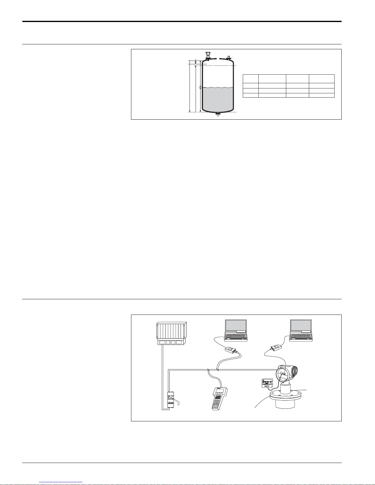
Function and system design
Prosonic M
Measuring principle
BD
20 mA
100%
BD: Blocking Distance
E: Empty calibration
F: Full calibration (span)
D: Distance from sensor
membrane to product level
L: Level
D
E
F
L
4 mA
0%
Sensor
FMU 40
FMU 41
FMU 43
BD
9.84" (250 mm)
15.7" (400 mm)
23.6" (600 mm)
Max. range
in liquids
16 ft (5 m)
26 ft (8 m)
50 ft (15 m)
Max. range
in solids
6.5 ft (2 m)
11.5 ft (3.5 m)
23 ft (7 m)
Time-of-Flight method
The Prosonic M sensor transmits ultrasonic pulses in the direction of the product
surface. The ultrasonic pulse is reflected back and received by the sensor. The
Prosonic M electronics measures the time t between pulse transmission and reception. Using the time t (and the velocity of sound c), the system calculates the distance
D between the sensor membrane and the product surface
D = c x t/2
As the device knows the empty distance E from the user entry, it can calculate the
level as follows:
L = E - D
An integrated temperature sensor compensates for changes in the velocity of sound
caused by temperature changes.
Interference echo suppression
The interference echo suppression feature ensures that interference echos (such as
welded joints, internal ladder steps, edges and installations) are not interpreted as a
level echo.
Equipment architecture
Calibration
Enter the empty distance E and the span F to calibrate the system.
Blocking distance
Span F may not extend into the blocking distance BD. Level echos within the blocking
distance cannot be evaluated due to the transient characteristics of the sensor.
4 to 20 mA ouput with HART
PLC
Transmitter power
supply unit
RMA 422
or RN 221 N
(communication resistor
included)
FXA 191
or
DXR 275
®
protocol
- COMMUWIN II
- ToF Tool
Commubox
FXA 191
Operating and
display module
VU 331
HART handheld
DXR 275
- ToF Tool
Service adapter
FXA 193
2
The Prosonic M can be operated on-site using either the display module VU 331 or
the supplied ToF Tool program. The system can also be operated remotely using the
HART® handheld terminal DXR 275 or using the ToF Tool.
®
NOTE: If a HART
communication resistor is not built into the power supply device, a
250Ω communication resistor in the 2-wire line must be inserted.
Endress+Hauser
Prosonic M
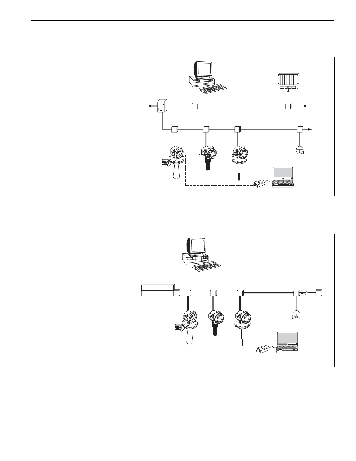
Profibus-PA protocol
Segment coupler
PROFIBUS-PA
Personal computer
e.t.with Commuwin II
or ToFTool and
Profibard (Proficard)
PROFIBUS-DP
PLC
Operating and
display module
VaU 331
Micropilot
Prosonic
Levelflex
FXA 193
ToF Tool
Additional
functions
(valves, etc.)
A maximum of 32 transmitters (8 if mounted in an explosion hazardous area) can be
connected to the bus. Both on-site as well as remote operation are possible.
Foundation Fieldbus (FF) protocol
Personal computer
e.g.with
NI-FBUS configurator
Power supply
Power conditioner
Operating and
display module
VaU 331
T
Levelflex
T
Additional
functions
(valves, etc.)
Endress+Hauser 3
Prosonic
Micropilot
FXA 193
ToF Tool
A maximum of 32 transmitters (standard or hazardous) can be connected to the bus.
For intrinsically safe circuits, the maximum number of transmitters depends on the
established rules and standards for intrinsically safe circuits (EN 60070-14) and proof
of instrinsic safety. Both on-site and remote operation are possible.
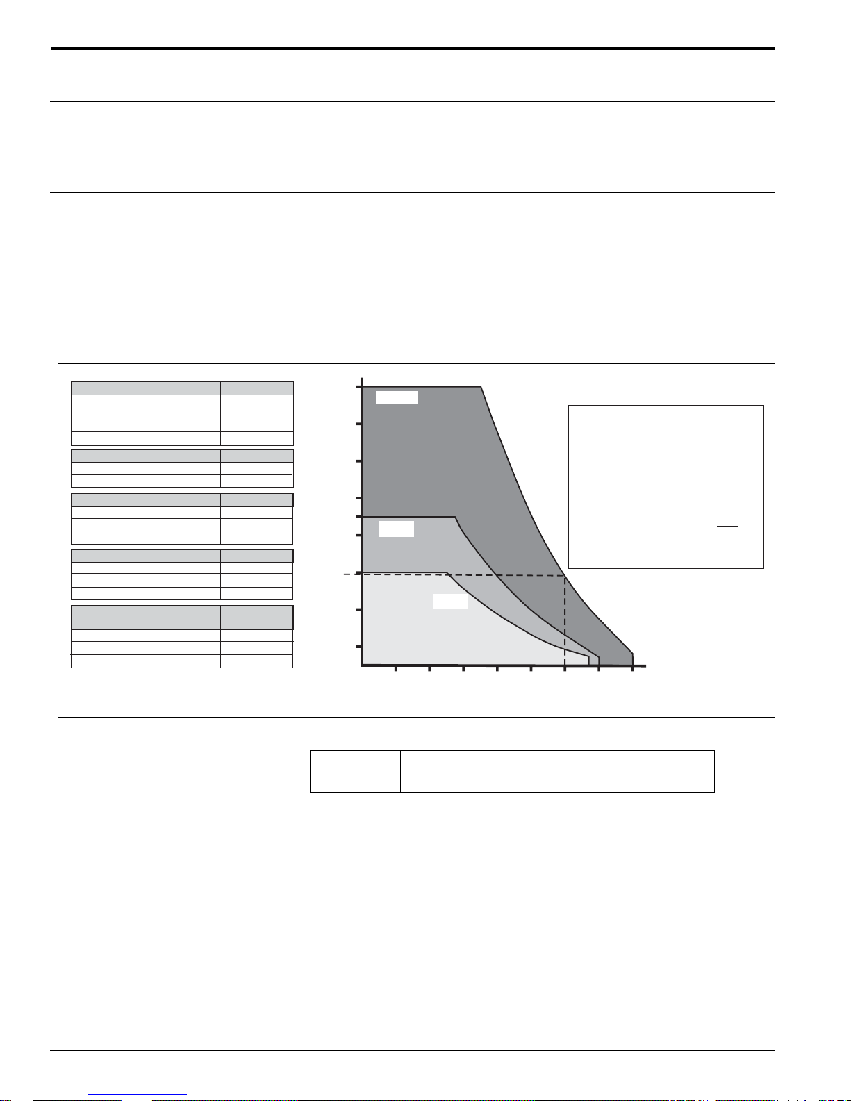
Input
Prosonic M
Measured variable
Measuring range
Fluid surface
Calm
Waves
Strong turbulence (agitators, etc.)
Foaming
Bulk material surface
Hard, rough (e.g.rubble)
Soft (e.g.peat, dust-covered clinker)
Dust
No dust formation
Little dust formation
Heavy dust formation
Filling curtain in detection range
None
Smalll quantities
Large quantities
Temperature difference between
sensor and surface
To 68°F (20°C)
To 104°F (40°C)
To 176°F (80°C)
Attenuation
0 dB
5 to 10 dB
10 to 20 dB
Consult factory
Attenuation
40 dB
40 to 60 dB
Attenuation
0 dB
5 dB
5 to 20 dB
Attenuation
0 dB
5 to 10 dB
10 to 40 dB
Attenuation
0 dB
5 to 10 dB
10 to 20 dB
The distance D between the sensor membrane and the product surface is measured
(page 2). Using the linearization function, the device uses D to calculate:
• Level L in any units
• Volume V in any units
• Flow Q across measuring weirs or open channels in any units
The measuring range is limited by the range of a sensor. The sensor range is, in turn,
dependent on operating conditions. The diagram below defines the effect that echo
attenuation has on the sensor’s measuring range. The ideal echo attenuation curves
for each sensor are shown in the diagram. A number of echo attenuation sources that
affect proper sensor selection are shown in the table.
1. Determine which of the influences shown are appropriate for your process.
2. Add the corresponding attenuation values.
3. From the total attenuation, use the diagram to calculate the sensor range.
50
FMU 43
Example (for FMU 43)
Dust-covered rubble
Medium dust development
Not in filling curtain
Temperature differential < 68°F
Approximate range = 15.5 ft.
Approximate dB
50
10
0
0
60 dB
range in feet
15.5
26
16
43
36
30
FMU 41
23
10
3
10 20 30 40 50 60 70 80
FMU 40
Attenuation / dB
Operating frequency
Pulse frequency
4
Sensor FMU 40 FMU 41 FMU 43
Frequency approx. 70 kHz approx. 50 kHz approx. 35 kHz
• 2-wire devices, maximum 0.5 Hz
• 4-wire devices, maximum 2 Hz
The exact values are dependent on the type of device and supply voltage.
Endress+Hauser
Prosonic M
1 234
1 234
Sealed terminal
compartment
F 12 Housing T 12 Housing
Output signal
Output
®
• 4 to 20 mA with HART
• Profibus-PA
• Foundation Fieldbus (FF)
protocol
Signal on alarm
Load HART
®
Output damping
Linearization
Terminal compartment
Error information can be accessed via the following interfaces:
• On-site display (error symbol, error code and plain text description)
• Current output (configurable)
• Digital interface
Minimum load for HART
®
communication, 250Ω
Freely selectable, 0 to 255 seconds
The linearization function of the Prosonic M allows conversion of the measured value
into any unit of length or volume. In open channels or measuring weirs, it is also
possible to linearize the flow. Linearization tables for calculating volume in horizontal
cylindrical tanks are preprogrammed. You can also enter any number of other tables
containing up to 32 value pairs either manually or semi-automatically (by filling the
vessel under controlled conditions). You can use the ToF Tool operating program to
calculate the table automatically for any tank form and then enter it into the device.
Power supply
Fieldbus plug connector
Endress+Hauser
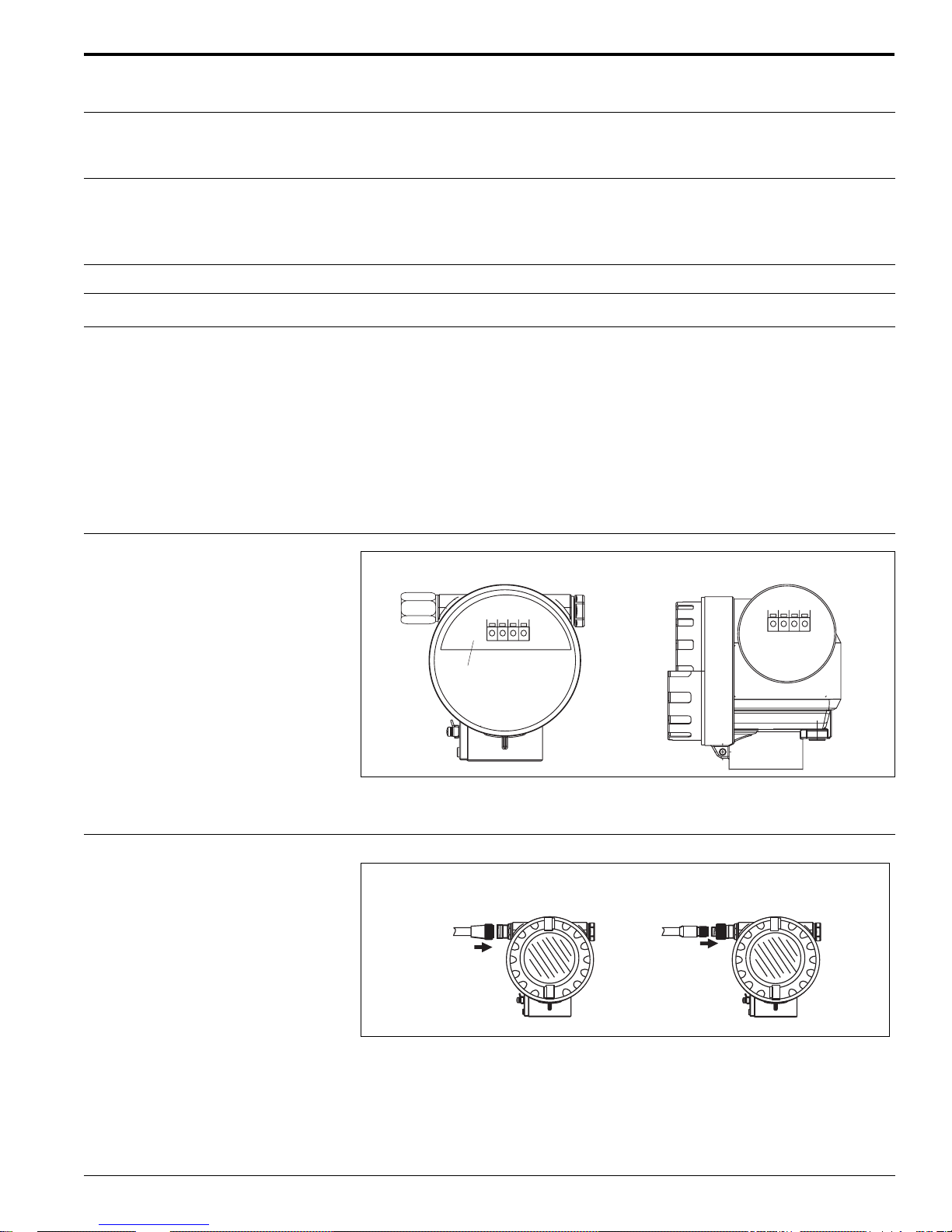
In the F 12 housing, the terminals are located underneath the housing cover. In the
T 12 housing, they are under the cover of the separate terminal compartment.
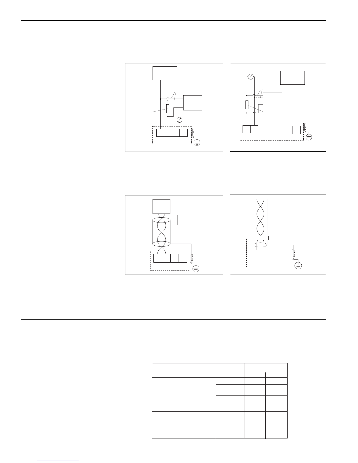
Foundation Fieldbus 7/8" plug
Profibus M 12 plug
• For the Foundation Fieldbus version, a 7/8” plug connector is available.
• For the Profibus-PA version, an M12 plug connector is available
Both versions are supplied fully wired.
5
Terminal assignment 4 to 20 mA with HART
FF+ FF-
1234
Plant
ground
Prosonic M
®
, 2-wire 4 to 20 mA with HART®, active,
4-wire
AC / DC
Auxiliary
power
12
L1/L+
N/L-
Plant
ground
Communication
resistor
(> 250 )Ω
Power:
4 to 20 mA
alternative
Test sockets
(via interlock diode)
1234
L- L+ I+ I-
Commubox
FXA 191
DXR 275
Plant
ground
0 to 20 mA
56
I-
I+
alternative
Commubox
FXA 191
DXR 275
Communication
resistor
(> 250 )Ω
• Connect the connecting line to the screw terminals (up to 18 AWG) in the terminal
compartment
• Use 2-wire twisted pair cable with shield for the connection
• Units are internally protected against reverse polarity, RFI and over-voltage peaks
PROFIBUS-PA Foundation Fieldbus
T-Box
3 412
PA+ PA-
Plant
ground
The digital communication signal is transmitted to the bus via a 2-wire connection.
The bus also provides the auxiliary power. Please use 2-wire twisted pair cable with
shield. Refer to the following operating manuals for information on cable types, and
how to set and ground the network:
• BA 198F/00/en “PROFIBUS-DP/-PA: Guidelines for planning and commissioning”
• BA 013S/04/en “Foundation Fieldbus, Installation and Commissioning Guidelines”
Cable entry
• Cable gland: M20x1.5, recommended cable diameter 0.23” to 0.39” (6 to 10 mm)
• Cable entry 1/2” NPT or G 1/2
• PROFIBUS-PA M12 plug
• Foundation Fieldbus 7/8” plug
Power supply The following values are the voltages across the terminals directly at the instrument.
Version
2-wire HART
Fixed current
(measured value
transmitted by HART)
4-wire
Standard
XP
Standard
DC
AC
consumption
IS
IS
Current
4 mA
20 mA
4 mA
20 mA
4 mA
20 mA
11 mA
11 mA
Terminal voltage
Min. Max.
14 V
8V
14 V
8V
14 V
11 V
10 V
10 V
10.5 VDC
90 VAC 253 VAC
36 V
36 V
30 V
30 V
30 V
30 V
36 V
30 V
32 VDC
6
Endress+Hauser
 Loading...