

Page 1
Technical
Information
TI 365F/24/ae
Ultrasonic Level Measurement
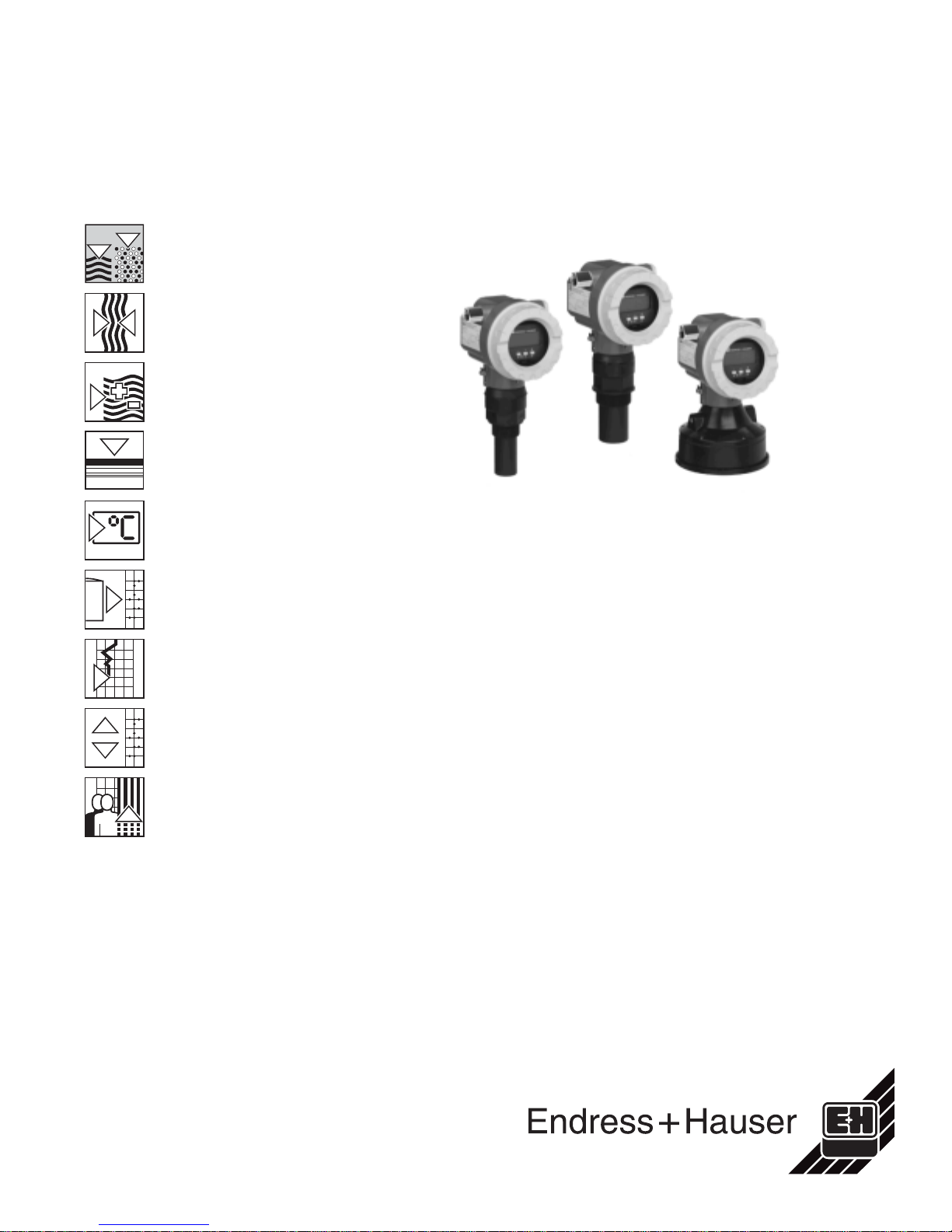
prosonic M FMU 40/41/43
Compact transmitters for non-contact level
measurement of fluids, pastes and coarse
bulk materials
FMU 41
FMU 40
Application
The compact Prosonic M transmitters are
used for continuous, non-contact level
measurement in fluids and coarse bulk
materials.
Additionally, the sensors can be used for
flow measurement in open channels and
measuring weirs.
The following interfaces are available for
system integration:
• HART
• PROFIBUS-PA
• Foundation Fieldbus
The maximum measuring range for
Prosonic M sensors are:
• FMU 40:
• FMU 41:
• FMU 43:
®
(standard), 4 to 20 mA
– Fluids, 16 feet (5 m)
– Bulk solids, 6 feet (2 m)
– Fluids, 26 feet (8 m)
– Bulk solids, 12 feet (3.5 m)
– Fluids, 50 feet (15 m)
– Bulk solids, 23 feet (7 m)
FMU 43
Features and benefits
• Simple, menu-guided on-site
operation with four-line plain text
display
• Envelope curves on the on-site
display for simple diagnosis
• Easy operation, diagnosis and
measuring point documentation with
the supplied ToF Tool operating
program
• Alignable NEMA 6P (IP 68) aluminum
housing
• Optional remote display and operation
• Installation via 1-1/2” NPT, 2” NPT
or 4” universal slip-on flange
• Integrated temperature sensor for
Time-of-Flight correction provides
accurate measurements, even with
temperature changes
• Linearization function (up to 32 points)
for measured value output in any unit
of length, volume, or flow rate
• Non-contact measurement method,
therefore almost independent of
product properties
The Power of Know How
Page 2
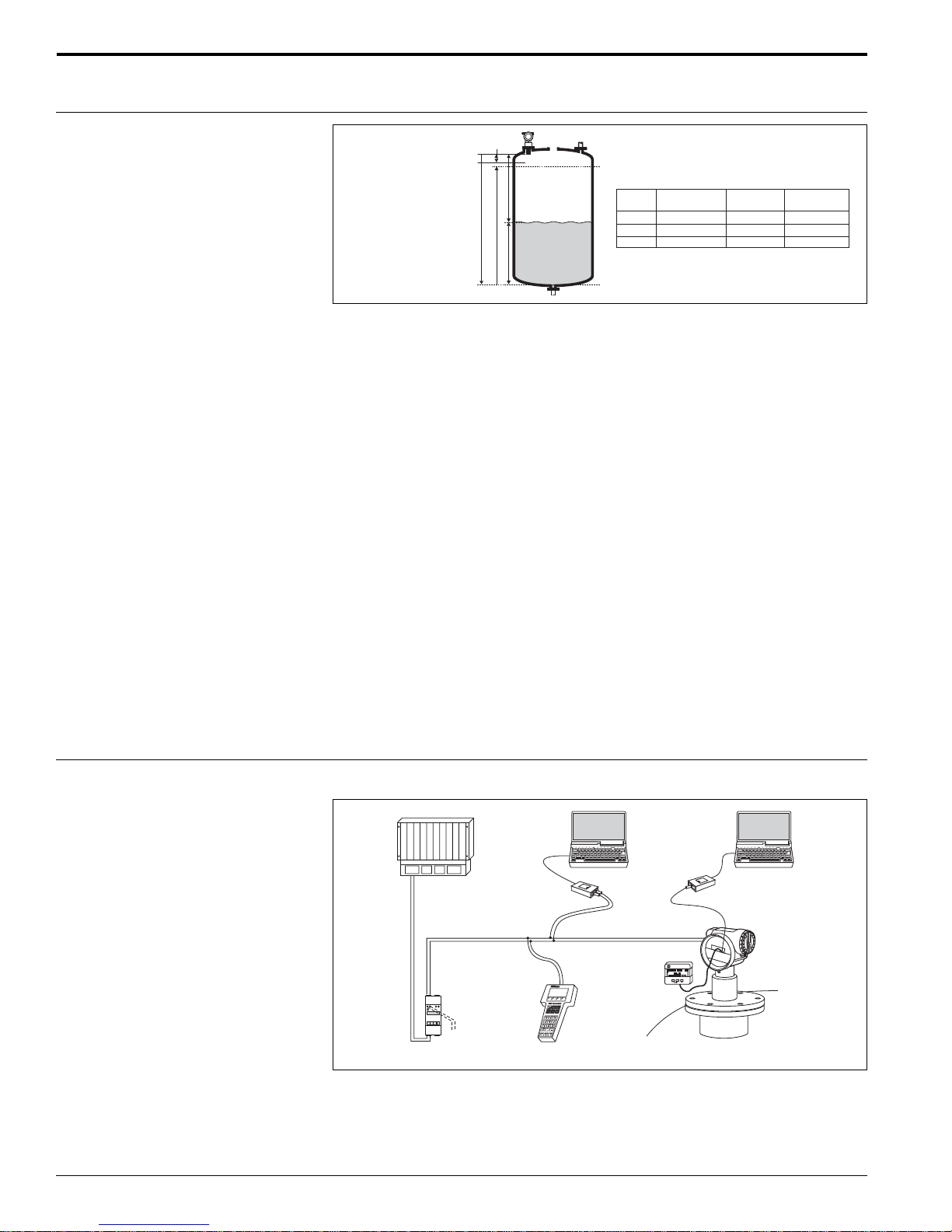
Function and system design
Prosonic M
Measuring principle
BD
20 mA
100%
BD: Blocking Distance
E: Empty calibration
F: Full calibration (span)
D: Distance from sensor
membrane to product level
L: Level
D
E
F
L
4 mA
0%
Sensor
FMU 40
FMU 41
FMU 43
BD
9.84" (250 mm)
15.7" (400 mm)
23.6" (600 mm)
Max. range
in liquids
16 ft (5 m)
26 ft (8 m)
50 ft (15 m)
Max. range
in solids
6.5 ft (2 m)
11.5 ft (3.5 m)
23 ft (7 m)
Time-of-Flight method
The Prosonic M sensor transmits ultrasonic pulses in the direction of the product
surface. The ultrasonic pulse is reflected back and received by the sensor. The
Prosonic M electronics measures the time t between pulse transmission and reception. Using the time t (and the velocity of sound c), the system calculates the distance
D between the sensor membrane and the product surface
D = c x t/2
As the device knows the empty distance E from the user entry, it can calculate the
level as follows:
L = E - D
An integrated temperature sensor compensates for changes in the velocity of sound
caused by temperature changes.
Interference echo suppression
The interference echo suppression feature ensures that interference echos (such as
welded joints, internal ladder steps, edges and installations) are not interpreted as a
level echo.
Equipment architecture
Calibration
Enter the empty distance E and the span F to calibrate the system.
Blocking distance
Span F may not extend into the blocking distance BD. Level echos within the blocking
distance cannot be evaluated due to the transient characteristics of the sensor.
4 to 20 mA ouput with HART
PLC
Transmitter power
supply unit
RMA 422
or RN 221 N
(communication resistor
included)
FXA 191
or
DXR 275
®
protocol
- COMMUWIN II
- ToF Tool
Commubox
FXA 191
Operating and
display module
VU 331
HART handheld
DXR 275
- ToF Tool
Service adapter
FXA 193
2
The Prosonic M can be operated on-site using either the display module VU 331 or
the supplied ToF Tool program. The system can also be operated remotely using the
HART® handheld terminal DXR 275 or using the ToF Tool.
®
NOTE: If a HART
communication resistor is not built into the power supply device, a
250Ω communication resistor in the 2-wire line must be inserted.
Endress+Hauser
Page 3
Prosonic M
Profibus-PA protocol
Segment coupler
PROFIBUS-PA
Personal computer
e.t.with Commuwin II
or ToFTool and
Profibard (Proficard)
PROFIBUS-DP
PLC
Operating and
display module
VaU 331
Micropilot
Prosonic
Levelflex
FXA 193
ToF Tool
Additional
functions
(valves, etc.)
A maximum of 32 transmitters (8 if mounted in an explosion hazardous area) can be
connected to the bus. Both on-site as well as remote operation are possible.
Foundation Fieldbus (FF) protocol
Personal computer
e.g.with
NI-FBUS configurator
Power supply
Power conditioner
Operating and
display module
VaU 331
T
Levelflex
T
Additional
functions
(valves, etc.)
Endress+Hauser 3
Prosonic
Micropilot
FXA 193
ToF Tool
A maximum of 32 transmitters (standard or hazardous) can be connected to the bus.
For intrinsically safe circuits, the maximum number of transmitters depends on the
established rules and standards for intrinsically safe circuits (EN 60070-14) and proof
of instrinsic safety. Both on-site and remote operation are possible.
Page 4
Input
Prosonic M
Measured variable
Measuring range
Fluid surface
Calm
Waves
Strong turbulence (agitators, etc.)
Foaming
Bulk material surface
Hard, rough (e.g.rubble)
Soft (e.g.peat, dust-covered clinker)
Dust
No dust formation
Little dust formation
Heavy dust formation
Filling curtain in detection range
None
Smalll quantities
Large quantities
Temperature difference between
sensor and surface
To 68°F (20°C)
To 104°F (40°C)
To 176°F (80°C)
Attenuation
0 dB
5 to 10 dB
10 to 20 dB
Consult factory
Attenuation
40 dB
40 to 60 dB
Attenuation
0 dB
5 dB
5 to 20 dB
Attenuation
0 dB
5 to 10 dB
10 to 40 dB
Attenuation
0 dB
5 to 10 dB
10 to 20 dB
The distance D between the sensor membrane and the product surface is measured
(page 2). Using the linearization function, the device uses D to calculate:
• Level L in any units
• Volume V in any units
• Flow Q across measuring weirs or open channels in any units
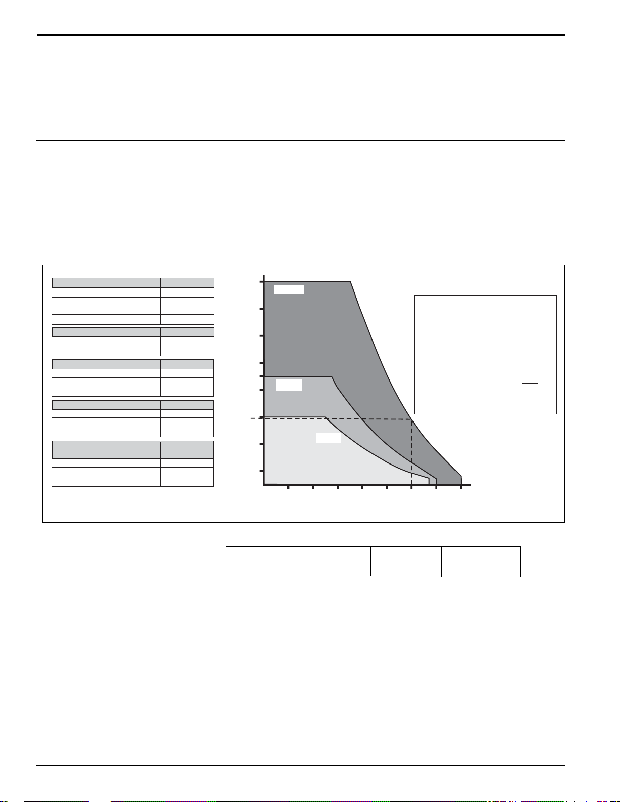
The measuring range is limited by the range of a sensor. The sensor range is, in turn,
dependent on operating conditions. The diagram below defines the effect that echo
attenuation has on the sensor’s measuring range. The ideal echo attenuation curves
for each sensor are shown in the diagram. A number of echo attenuation sources that
affect proper sensor selection are shown in the table.
1. Determine which of the influences shown are appropriate for your process.
2. Add the corresponding attenuation values.
3. From the total attenuation, use the diagram to calculate the sensor range.
50
FMU 43
Example (for FMU 43)
Dust-covered rubble
Medium dust development
Not in filling curtain
Temperature differential < 68°F
Approximate range = 15.5 ft.
Approximate dB
50
10
0
0
60 dB
range in feet
15.5
26
16
43
36
30
FMU 41
23
10
3
10 20 30 40 50 60 70 80
FMU 40
Attenuation / dB
Operating frequency
Pulse frequency
4
Sensor FMU 40 FMU 41 FMU 43
Frequency approx. 70 kHz approx. 50 kHz approx. 35 kHz
• 2-wire devices, maximum 0.5 Hz
• 4-wire devices, maximum 2 Hz
The exact values are dependent on the type of device and supply voltage.
Endress+Hauser
Page 5
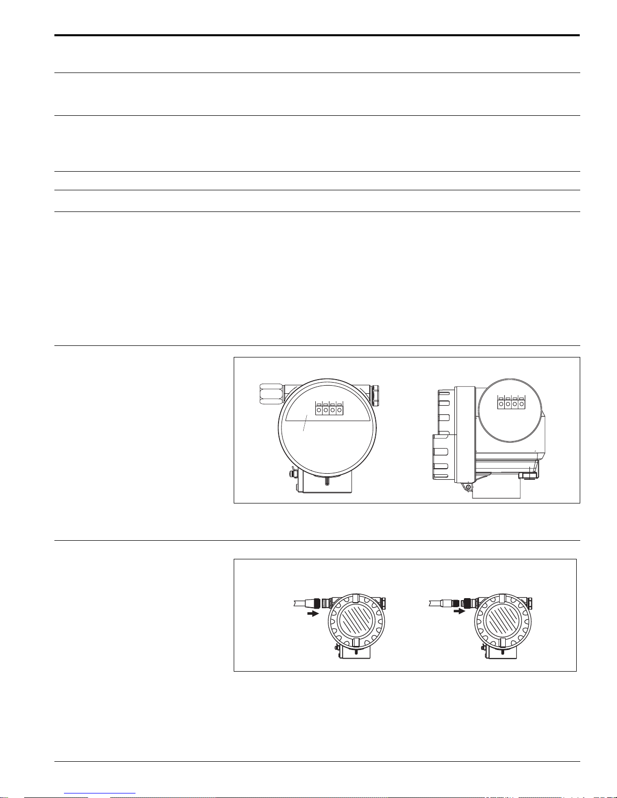
Prosonic M
1 234
1 234
Sealed terminal
compartment
F 12 Housing T 12 Housing
Output signal
Output
®
• 4 to 20 mA with HART
• Profibus-PA
• Foundation Fieldbus (FF)
protocol
Signal on alarm
Load HART
®
Output damping
Linearization
Terminal compartment
Error information can be accessed via the following interfaces:
• On-site display (error symbol, error code and plain text description)
• Current output (configurable)
• Digital interface
Minimum load for HART
®
communication, 250Ω
Freely selectable, 0 to 255 seconds
The linearization function of the Prosonic M allows conversion of the measured value
into any unit of length or volume. In open channels or measuring weirs, it is also
possible to linearize the flow. Linearization tables for calculating volume in horizontal
cylindrical tanks are preprogrammed. You can also enter any number of other tables
containing up to 32 value pairs either manually or semi-automatically (by filling the
vessel under controlled conditions). You can use the ToF Tool operating program to
calculate the table automatically for any tank form and then enter it into the device.
Power supply
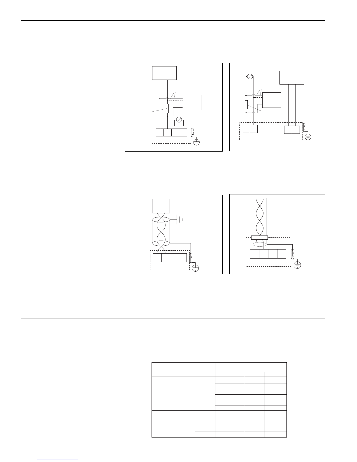
Fieldbus plug connector
Endress+Hauser
In the F 12 housing, the terminals are located underneath the housing cover. In the
T 12 housing, they are under the cover of the separate terminal compartment.
Foundation Fieldbus 7/8" plug
Profibus M 12 plug
• For the Foundation Fieldbus version, a 7/8” plug connector is available.
• For the Profibus-PA version, an M12 plug connector is available
Both versions are supplied fully wired.
5
Page 6
Terminal assignment 4 to 20 mA with HART
FF+ FF-
1234
Plant
ground
Prosonic M
®
, 2-wire 4 to 20 mA with HART®, active,
4-wire
AC / DC
Auxiliary
power
12
L1/L+
N/L-
Plant
ground
Communication
resistor
(> 250 )Ω
Power:
4 to 20 mA
alternative
Test sockets
(via interlock diode)
1234
L- L+ I+ I-
Commubox
FXA 191
DXR 275
Plant
ground
0 to 20 mA
56
I-
I+
alternative
Commubox
FXA 191
DXR 275
Communication
resistor
(> 250 )Ω
• Connect the connecting line to the screw terminals (up to 18 AWG) in the terminal
compartment
• Use 2-wire twisted pair cable with shield for the connection
• Units are internally protected against reverse polarity, RFI and over-voltage peaks
PROFIBUS-PA Foundation Fieldbus
T-Box
3 412
PA+ PA-
Plant
ground
The digital communication signal is transmitted to the bus via a 2-wire connection.
The bus also provides the auxiliary power. Please use 2-wire twisted pair cable with
shield. Refer to the following operating manuals for information on cable types, and
how to set and ground the network:
• BA 198F/00/en “PROFIBUS-DP/-PA: Guidelines for planning and commissioning”
• BA 013S/04/en “Foundation Fieldbus, Installation and Commissioning Guidelines”
Cable entry
• Cable gland: M20x1.5, recommended cable diameter 0.23” to 0.39” (6 to 10 mm)
• Cable entry 1/2” NPT or G 1/2
• PROFIBUS-PA M12 plug
• Foundation Fieldbus 7/8” plug
Power supply The following values are the voltages across the terminals directly at the instrument.
Version
2-wire HART
Fixed current
(measured value
transmitted by HART)
4-wire
Standard
XP
Standard
DC
AC
consumption
IS
IS
Current
4 mA
20 mA
4 mA
20 mA
4 mA
20 mA
11 mA
11 mA
Terminal voltage
Min. Max.
14 V
8V
14 V
8V
14 V
11 V
10 V
10 V
10.5 VDC
90 VAC 253 VAC
36 V
36 V
30 V
30 V
30 V
30 V
36 V
30 V
32 VDC
6
Endress+Hauser
Page 7

Prosonic M
Power consumption 2-wire, 51 mW to 800 mW
4-wire AC, maximum 7W
4-wire DC FMU 40/41, 330 mW to 830 mW
4-wire DC FMU 43, 600 mW to 1 W
®
, 3.6 to 22 mA
Current consumption (2-wire units)
HART
PROFIBUS-PA, maximum 13 mA
Foundation Fieldbus, maximum 15 mA
HART® ripple
Maximum noise HART
®
Galvanic isolation
Reference operating conditions
Measuring error
Measured value resolution
47 to 125 Hz: Vpp = 200 mV (measured at 500 W)
500 Hz to 10 kHz: Vrms = 2.2 mV (measured at 500 W)
With 4-wire units, the evaluation electronics and power supply voltage are
galvanically isolated from each other
Performance characteristics
• Temperature = 68°F (20°C)
• Pressure = 14.7 psia (1013 mbar abs.)
• Humidity = 50%
• Ideal reflective surface (calm, smooth fluid surface)
• No interference reflections within signal beam area
• Set application parameters:
Tank shape = flat ceiling
Medium property = liquid
Process conditions = calm surface
Typical specifications for reference operating conditions (include linearity,
repeatability, and hysteresis):
FMU 40 / 41: ± 0.08” (2 mm) or 0.2% of set measuring range, which ever is greater
FMU 43: ± 0.15” (4 mm) or 0.2% of set measuring range, which ever is greater
FMU 40 / 41: 0.04” (1 mm)
FMU 43: 0.08” (2 mm)
Reaction time
The reaction time depends on the parameter settings (minimum 0.5 seconds for
4-wire devices, minimum 2 seconds for 2-wire devices)
Endress+Hauser
7
Page 8

Installation conditions
Prosonic M
FMU 40/41 installation variants
Installation with counter nut
Counter nut supplied
for G 1-1/2 and G2
instruments
Installation with extension bracket
ENDRESS+HAUSER
Prosonic M
Installation with sleeve
Installation with adapter flange
Adapter flange
EPDM sealing
ring supplied
EPDM sealing
ring supplied
FMU 43 installation variants
Slip-on flange
Nozzle
Installation with
universal slip-on flange
Sensor
Hazardous area or non-hazardous
Sensor
Installation with
mounting bracket
R
E
S
U
A
H
+
S
S
E
R
D
N
E
M
ic
n
o
s
ro
P
Non-hazardous area
Nozzle
8
Endress+Hauser
Page 9

Prosonic M
ENDRESS+HAUSER
Prosonic MProsonic M
ENDRESS+HAENDRESS+HAUSERUSER
Prosonic MProsonic M
Venting
hole
Installation conditions for level
measurement
• Do not install the sensor in the middle of the tank (3). Mounting distance between
• Use a protective cover (see accessories, page 18), to protect the sensor from rain
• Avoid measurements in the filling stream area (4).
• Make sure that equipment (5) such as limits swtiches, temperature sensors, etc.
• Align the sensor so that it is vertical to the product surface (7).
• Never install two ultrasonic measuring devices in the same vessel, as the two
• To estimate the transmitted echo beam and its detection range, use the 3 dB
234
1
1/6D
D
5
6
FMU 40
FMU 41
FMU 43
α
r
r = L tan
α
11°
11°
6°
L
α
2
LSensor
16 ft (5 m)
26 ft (8 m)
50 ft (15 m)
18.9" (480 mm)
30.3" (770 mm)
31.1" (790 mm)
7
r
vessel wall and sensor (1) should be 1/6 of the tank diameter.
or direct sunlight (2).
are not located in the beam angle α. In particular, symmetrical equipment (6) such
as heating coils, baffles, stationary ladder rungs etc. can influence measurement.
signals may affect each other.
emitting angle α (see Figure above).
Installation in narrow shafts In narrow shafts with strong interference
Endress+Hauser
echoes, we recommend using an
ultrasound guide pipe (e.g. PE or PVC
wastewater pipe) with a minimum
diameter of 4” (100 mm). Make sure that
the pipe does not accumulate dirt, clean
pipe at regular intervals.
9
Page 10

Prosonic M
Installation conditions for flow
measurements
• Install the Prosonic M at the inflow side, as close above the maximum water
level H
• Position the Prosonic M in the middle of the channel or weir.
as possible, plus the blocking distance BD.
max
• Align the sensor membrane parallel to the water surface.
• Keep to the installation distance of the channel or weir.
• The “Flow to Level” linearization curve (“Q/h curve”) can be entered using the
ToF Tool or manually via the on-site display.
Example: Khafagi-Venturi flume
Khafagi -Venturi - flume
BD
inflow
o
b
o
direction of flow
H
max
1 x b
outflow
Blocking distance with nozzle
installation
BD
SD
E
F
BD: Blocking Distance
SD: Safety Distance
E: Empty calibration
F: Full calibration (span)
FMU 40/41
L
D
Sensor
FMU 40
FMU 41
FMU 43
FMU 43
L
D
BD Max. range
9.84" (250)
15.7" (400)
23.6" (600)
16 ft (5 m)
26 ft (8 m)
50 ft (15 m)
in liquids
1.97" (50)
3.15" (80)
3.94" (100)
3.15" (80)
3.94" (100)
FMU 40
D (mm) max. L (mm)
approx.3.15" (80)
approx.7.87" (200)
approx.9.84 (250)
FMU 41
D (mm) max. L (mm)
D > approx.3.94" (100)
L < approx.11.8" (300)
approx.7.87" (200)
approx.9.84 (250)
FMU 43
Max. range
in solids
6.5 ft (2 m)
11.5 ft (3.5 m)
23 ft (7 m)
Install the Prosonic M at a height so that the blocking distance BD is not interferred
with, even at the maximum fill level. Usa a pipe nozzle if you cannot maintain the
sensor blocking distance in any other way. The interior of the nozzle must be smooth
and cannot contain any edges or welded joints. In particular, remove any burr on the
inside of the tank side nozzle end. Note the specified limits for nozzle diameter to
length. Nozzles which extend into the vessel should be cut at an angle of 45° to
minimize echo disturbances.
10
Caution !
The sensor may malfunction if the blocking distance is not above the maximum level.
NOTE: In order to prevent the level from entering the blocking distance, a safety
distance (SD) can be specified. If the level is within the safety distance, the Prosonic
outputs a warning or alarm message.
Endress+Hauser
Page 11

Prosonic M
Ambient conditions
Ambient temperature
Storage temperature
Resistance to alternating
temperature cycles
Climate class
Ingress protection
Vibration resistance
Electromagnetic compatibility (EMC)
-40° to + 176°F (-40° to + 80°C)
The function of the LCD becomes restricted at T
and 60°C). If the device is operated outdoors in strong sunlight, a protective cover
< -5°F and T
amb
> 140°F (-20°C
amb
should be used.
-40° to +176°F (-40° to +80°C)
To DIN EN 60068-2-14; Nb test: 176°F / -40°F (+80°C / -40°C), 1 K/min, 100 cycles
DIN EN 60068-2-38 (Test Z/AD) EIN/IEC 68 T2-30Db
• With closed housing, tested according to NEMA 6P (IP 68), 24 hours at 6 feet
(1.83 m) under water surface.
NEMA 4X (IP 66)
• With open housing, NEMA 1 (IP 20)
DIN EN 60068-2-64 / IEC 68-2-64: 20 to 2000 Hz, 1 (m/x
2)2
/Hz; 3 x 100 min
• Interference emission to EN 61326, Equipment Class B
• Interference immunity to EN 61326, Appendix A (Industrial) and NAMUR
Recommendation NE 21 (EMC)
• A standard installation cable is sufficient if only the analog signal is used. Use
shielded cable when working with a superimposed communication signal (HART
Process conditions
®
)
Process temperature -40° to +176°F (-40° to +80°C)
A temperature sensor is integrated in the sensor for temperature-dependent
time-of-flight correction.
Process pressure
• FMU 40/41: 44 psia (3 bar abs.)
• FMU 43: 36 psia (2.5 bar ads.)
Mechanical construction
FMU 40 / 41 dimensions
Dimensions are in inches (mm)
3.38"
(86)
1-1/2" NPT
(G 1-1/2)
F12 housing
2.26"
3.07"
(65)
(78)
3.35"
(85)
FMU 40 FMU 41
60 AF
3.43"
(87)
0.87"
(22)
∅ 1.54"
(39)
5.83"
(148)
∅ 5.08"
(129)
5.91"
(150)
2" NPT
(G 2)
2.68"
(68)
60 AF
∅ 1.97"
(50)
T12 housing
3.70"
(94)
0.87"
(22)
3.27"
(83)
2.26"
(65)
1.26"
(32)
5.83"
(148)
3.07"
(78)
3.35"
(85)
∅ 5.08"
(129)
6.38"
(162)
Endress+Hauser
11
Page 12

FMU 43 dimensions
Prosonic M
3.39"
(80)
2 x M8
2.56"
(65)
∅ 9.05"
(230)
3.07"
(78)
∅ 5.08"
(129)
Dimensions are in inches (mm)
Weight • FMU 40: Approximately 5.5 lb (2.5 kg)
• FMU 41: Approximately 6 lb (2.6 kg)
• FMU 43: Approximately 8 lb (3.5 kg)
Housing
Types of housings:
• F 12 housing with sealed terminal compartment for standard or hazardous areas
• T 12 housing with separate terminal compartment for explosion proof areas
Material:
• Aluminum, chromed, powder-coated, seawater resistant
Cover:
• Aluminum, for version without on-site display
• Inspection glass for version with on-site display (this version cannot be specified
with the ATEX II 1/2 D certificate)
3.35"
(85)
5.90"
(150)
9.76"
(248)
4.72"
(120)
1.57"
(40)
4.68"
(119)
0.08"
1.57"
(40)
(2)
0.43"
(11)
3.50"
(89)
0.98"
(25)
0.98"
(25)
4.84"
(123)
Process connection and sensor
material
12
FMU 40: 1-1/2” NPT or G1-1/2, PVDF sensor material with EPDM seal
FMU 41: 2” NPT or G 2, PVDF sensor material with EPDM seal
FMU 43: Universal slip-on flange, 4” ANSI or mounting bracket, PVDF sensor
material, 316 Ti SS diaphragm
Endress+Hauser
Page 13

Prosonic M
E
+–
E
N
D
R
E
S
S
+
H
A
U
S
E
R
M
I
C
R
O
P
I
L
O
T
I
I
I
P
6
5
O
r
d
e
r
C
o
d
e
:
Se
r
.-
N
o
.
:
M
e
s
s
be
re
ic
h
M
e
a
s
u
r
i
n
g
r
a
n
ge
U
16
.
..
3
6
V
D
C
4
.
..
2
0
m
A
m
a
x
.
2
0
m
Made i
n Germ
any
M
aulburg
T
>
7
0
°
C
:
A
t
>
8
5
°
C
Symbols
3 keys
ENDRESS+HAUSER
LCD
Human interface
Display elements The LCD module VU 331 for display and operation is located beneath the housing
cover. The measured value is legible through the glass in the cover. Open the cover
to operate the device.
Displayed
Symbol
Meaning
ALARM symbol
Symbol appears when the instrument is in an alarm state. Flashing indicates
warning, steady ON indicates alarm.
LOCK symbol
The lock symbol appears when the instrument is locked;input is not possible
during the locked state.
COMMUNICATION symbol
Communication symbol appears when data transmission via HART, PROFIBUS,
or Foundation Fieldbus is in progress.
Key (s)
+
-
Esc
-
E
+
-
Or
Or
+
Or
and
or
and
Or
Meaning
Navigate upwards in the selection list
Edit numeric value within a function
Navigate downwards in the selection list
Edit numeric value within a function
Navigate to the left within a function group
Navigate to the right within a function group, confirmation
E
E
Contrast settings of the LCD
E
Hardware lock / unlock
After a hardware lock, an operation via the display or
+
and and
-
communication is not possible.
E
The hardware can only be unlocked via the display. An
unlock parameter must be entered to do so.
Endress+Hauser
13
Page 14

On-site operation Operation with VU 331
The LC-Display VU 331 allows configuration via 3 keys directly at the instrument. All
device functions can be set through a menu system. The menu consists of function
groups and functions. Within a function, application parameters can be read or
adjusted. The user is guided through a complete configuration procedure.
ENDRESS + HAUSER
Prosonic M
Headline Position indicator
+–
E
Function groups -> Functions
HOME
+
-
E
+
-
FG00
FG01
FG02
FG03
FG04
FG05
FG06
FG07
...
Esc
+
F000 F001 F002 F003 F004 ...
-
E
E
+
Esc
-
Operation with DXR 275 HART
E
Esc
-
+
®
terminal
Selection list
+
Envelope
curve
Symbol
Help text
Main value
Bar graph
Unit
On units with HART® communication, access to the programming matrix can be done
using a handheld DXR 275 terminal.
FMU43: LIC0001
FMR 231:LIC0001
Online
1 >Group Select
2 PV 8.7 m
HELP
I
O
Online
1->Group Select
2 PV 8.7m
HELP
F1 F4F2 F3
FMU43 : LIC0001
Group Select
1->Calibration
2 Safety settings
3 Temperature
4 Linearization
5 Extended calibr.
F1 F4F2 F3
HOME
FMU43: LIC0001
Calibration
1 Measured Value
2->Tank shape
3 Medium property
4 Process cond.
5 Empty calibr.
HOME
F1 F4F2 F3
13
14
Endress+Hauser
Page 15

Prosonic M
Remote operation
Operation with ToF Tool
The ToF Tool is a graphical operation software for instruments from Endress+Hauser
that operate based on the time-of-flight principle. It is used to support commissioning,
securing of data, signal analysis and documentation of the instruments. It is compatible with the f ollo wing operating systems: Win95, Win98, WinNT4.0 and Win2000.
The ToF Tool suppor ts the following functions:
• Online configuration of transmitters
• Signal analysis via envelope curve
• Loading and saving of instrument data (Upload/Download)
• Documentation of measuring point
Menu-guided commissioning
Functions
Function
groups
Navigation bar
Main window
Help pages
Device
list
Signal analysis via envelope curve
Envelope
curve
Data at
cursor position
Evaluated echo
Device data
Parameter list
Envelope
list
Curve
data
Endress+Hauser
Connection options (page 2 and 3):
®
• HART
with Commubox FXA 191 (available as accessory)
• PROFIBUS-PA
• Service-interface with adapter FXA 193 (available as accessory)
15
Page 16

Prosonic M
Operation with Commuwin II (for communication versions HART
®
or
PROFIBUS-PA)
Commuwin II is an operating software with graphical support (MS Windows) for
intelligent transmitters with the communication protocols Rackbus, Rackbus RS-485,
HART® and PROFIBUS-PA.
Commuwin II supports the following functions:
• Online configuration of transmitters
• Loading and saving of instrument data (Upload/Download)
• Orderly visulization of measured values and limit values
• Display and recording of measured values with a line recorder
NOTE: It is not possible to display envelope curves with Commuwin II. To display
curves, use the ToF Tool program supplied.
Connections (page 3):
• HART® with Commubox FXA 191 (available as accessory)
• PROFIBUS-PA
Operation with NI-FBUS Configurator (only with Foundation Fieldbus)
The NI-FBUS Configurator is an easy-to-use graphical environment for creating
linkages, loops, and a schedule based on the fieldbus concepts.
The NI-FBUS Configurator is used to configure a fieldbus network as follows:
• Set block and device tags
• Set device addresses
• Create and edit function block control strategies (function block applications)
• Configure vendor-defined function and transducer blocks
• Create and edit schedules
• Read and write to function block control strategies (function block applications)
• Invoke Device Description (DD) methods
• Download a configuration
• Verify a configuration and compare it to a saved configuration
• Monitor a downloaded configuration
• Replace devices
• Save and print a configuration
Endress+Hauser16
Page 17

Prosonic M
Certificates and Approvals
CE mark By attaching the CE mark, Endress+Hauser confirms that the instrument fulfills all the
requirements of the relevant EC directives.
Hazardous areas
FMU 40
1 2 3 4 5 6
FMU 40 -
1 Certificate
A Non-hazardous version
S FM IS Cl. I, II, III; Div. 1, Grps. A-G
FM NI Cl. I, Div. 2
T FM XP Cl. I, II, III; Div . 1, Grps. A-G
U CSA IS Cl. I, II, III; Div. 1, Grps. A-G
CSA NI Cl. I, Div. 2
V CSA XP Cl. I, II, III; Div. 1, Grps. A-G
N CSA General purpose
2 Process connection
R G 1-1/2, ISO 228
N 1-1/2” NPT
3 Power supply / communication
B 2-wire, 4 to 20 mA loop-powered / HART
H 4-wire, 10.5 to 32 VDC / 4 to 20 mA HART
G 4-wire, 90 to 253 VAC / 4 to 20 mA HART
D 2-wire PROFIBUS-PA
F 2-wire Foundation Fieldbus
4 Display / operation
1 Without LCD
2 With LCD VU 331 / on-site operation
5 Housing
A F12 aluminum housing, coated, NEMA 6P
C T12 aluminum housing with separate
terminal
compartment, coated, NEMA 6P
6 Cable entry
2 M 20 x 1.5
3 G 1/2
4 1/2” NPT
5 M 12 PROFIBUS-PA plug-in connector
6 7/8” Foundation Fieldbus plug-in connnector
FMU 40 / 41:
• FM approved Intrinsically safe Class I, II, III; Division 1, Groups A-G / Nonincendive Class I, Division 2
• FM approved explosion proof Class I, II, III; Division 1, Groups A-G
• CSA approved Intrinsically safe Class I, II, III; Division 1, Groups A-G / Nonincendive Class I, Division 2
• CSA approved explosion proof Class I, II, III; Division 1, Groups A-G
FMU 43:
• FM approved dust-ignition proof Class I, Division 2, Groups E-G, non-incendive
• CSA approved dust-ignition proof Class I, Division 2, Groups E-G, non-incendive
Ordering Information
FMU 41
1 2 3 4 5 6
FMU 41 -
1 Certificate
A Non-hazardous version
S FM IS Cl. I, II, III; Div. 1, Grps. A-G
FM NI Cl. I, Div. 2
T FM XP Cl. I, II, III; Div . 1, Grps. A-G
U CSA IS Cl. I, II, III; Div . 1, Grps. A-G
CSA NI Cl. I, Div. 2
V CSA XP Cl. I, II, III; Div. 1, Grps. A-G
N CSA General purpose
2 Process connection
R G 2, ISO 228
N 2” NPT
3 Power supply / communication
®
®
®
B 2-wire, 4 to 20 mA loop-powered / HART
H 4-wire, 10.5 to 32 VDC / 4 to 20 mA HART
G 4-wire, 90 to 253 VAC / 4 to 20 mA HART
D 2-wire PROFIBUS-PA
F 2-wire Foundation Fieldbus
4 Display / operation
1 Without LCD
2 With LCD VU 331 / on-site operation
5 Housing
A F12 aluminum housing, coated, NEMA 6P
C T12 aluminum housing with separate
terminal compartment, coated, NEMA 6P
6 Cable entry
2 M 20 x 1.5
3 G 1/2
4 1/2” NPT
5 M 12 PROFIBUS-PA plug-in connector
6 7/8” Foundation Fieldbus plug-in connnector
FMU 43
1 2 3 4 5 6
FMU 43 -
1 Certificate
M FM DIP CI. 1, Div. 2, Grps. E-G, NI
N CSA General purpose
P CSA DIP CI. 1, Div. 2, Grps. E-G, NI
2 Process connection
P 4” ANSI flange, PP (universal slip-on
flange included)
S 4” ANSI flange, 316Ti SS (universal slip-on
flange included)
3 Power supply / communication
H 4-wire, 10.5 to 32 VDC / 4 to 20 mA HART
G 4-wire, 90 to 253 VAC / 4 to 20 mA HART
®
®
®
D 2-wire PROFIBUS-PA
F 2-wire Foundation Fieldbus
4 Display / operation
1 Without LCD
2 With LCD VU 331 / on-site operation
5 Housing
A F12 aluminum housing, coated, NEMA 6P
6 Cable entry
2 M 20 x 1.5
3 G 1/2
4 1/2” NPT
5 M 12 PROFIBUS-PA plug-in connector
6 7/8” Foundation Fieldbus plug-in connnector
®
®
Endress+Hauser 17
Page 18

Prosonic M
Accessories
Protective cover A protective cover made of stainless steel is available for outdoor installation. Cover,
mounting ring and hardware inlcuded.
Part Number: 543199-0001
F12 / T 12 housing
E
N
D
R
M
E
Order Code:
I
S
C
S
R
+
O
Ser
H
P
A
.-No
I
L
U
O
S
.:
T
E
I
R
I
Messbereich
Measur
ing r
ange
U 16...36
max.
4...20 mA
20 m
V DC
I
P
6
5
T
A
>70°C
:
t
>
8
5
°C
Made in Germany Maulburg
FHX 40 remote display and operating
unit
F 12 housing
E
N
D
R
E
O
S
r
d
S
e
r
C
+
S
H
o
e
d
A
r
e
.-
:
U
N
o
S
.
:
E
R
M
e
s
s
M
b
e
e
re
a
s
i
c
u
h
r
in
g
r
a
n
g
e
U
m
1
a
6
x
.
.
.
.
4
2
3
..
0
6
.2
m
V
0
D
m
C
A
Maulburg
I
P
6
5
T
A
>
7
0
°
C
:
t
>
8
5
°
C
Made in Germany
FHX 40 separate housing
5.9"
(150)
4.8"
(122)
3.15"
(80)
Cable
The FHX 40 provides remote display and operation for the FMU 40/41/43 units. The
display unit must be specified when ordering the Prosonic M sensors, it cannot be
retrofited due to the preinstallation of the plug connectors. Maximum cable length is
65 feet (20 m).
• Temperature range: -22° to +158°F (-30° to +70°C)
• Protection: NEMA 4 (IP 65)
• Material: Aluminium alloy AL Si 12
• Maximum cable length: 65 ft. (20 m)
Consult factory for ordering information.
Installation bracket for FMU 40/41
ENDRESS+HAUSER
Prosonic M
15.7"
(400)
0.12"
(3)
9.84"
(250)
4.72"
(120)
4.72"
(120)
1.18"
(30)
∅ 0.63"
(16)
For FMU 40, order no.942669-0000
For FMU 41, order no.942669-0001
Endress+Hauser18
Page 19

Prosonic M
Adapter flange for FMU 40/41
FXA 191 commubox
FXA 193 service adapter
Adapter flange for the FMU 40/41 threaded Prosonic M units for mounting on existing
nozzles or applications requiring a nozzle mount.
1 2 3
FAU 70 A -
1 Version
12 2” ANSI, Class 150
14 3” ANSI, Class 150
15 4” ANSI, Class 150
2 Thread
3 1-1/2” NPT
4 2” NPT
3 Material
2 317L SS
7 PPS (Polypropylene)
For intrinsically safe communication between HART
Sealing ring
EPDM
(supplied)
Sensor
®
protocol and Personal Computer
Nozzle
Adapter
flange
(refer to page 2). The Prosonic M can be operated either with the ToF Tool or the
Commuwin II program. The commubox coverts HART® protocol signals into
RS 232C signals.
Additional information is available in Technical Information TI 237F/00/en.
For comunication with ToF Tool via the display connector (refer to page 3).
Order No.: 50095566
Endress+Hauser 19
Page 20

Supplemental documentation
Device function description
Operating manual
BA 240F/00/en
This document contains detailed descriptions of all Prosonic M functions and is valid
for all communication variants
Communication operating manuals
The following operating manuals are supplied with the unit depending on the communication version ordered.
4 to 20 mA, HART
®
BA 237F/00/en
PROFIBUS-PA BA 238F/00/en
Foundation Fieldbus BA 239F/00/en
These manuals describe the installation and initial commissioning of the Prosonic M.
From the operating menu, all functions are included, which are required for standard
measurement tasks. Additional functions are not contained in the manual.
For application and selection assistance, in the U.S.
call 888-ENDRESS
For total support of your installed base, 24 hours
a day, in the U.S. call 800-642-8737
Visit us on our web site, www.us.endress.com
United States
Endress+Hauser, Inc.
2350 Endress Place
Greenwood, IN 46143
Phone: (317) 535-7138
888-ENDRESS
FAX: (317) 535-8498
TI 365F/24/ae/03.02
© 2002 Endress+Hauser, Inc.
Canada
Endress+Hauser
Canada Ltd.
1440 Graham’s Lane
Unit 1, Burlington
ON, L7S 1W3
Phone: (905) 681-9292
800-668-3199
FAX: (905) 681-9444
Mexico
Endress+Hauser
Paseo del Pedregal No. 610
Col. Jardines del P edregal
01900, Mexico D .F.
Mexico
Phone: (525) 568-2405
FAX: (525) 568-7459
Endress+Hauser
The Power of Know How
 Loading...