

Page 1
TI00365F/00/EN/17.14
71275861
Products Solutions Services
Technical Information
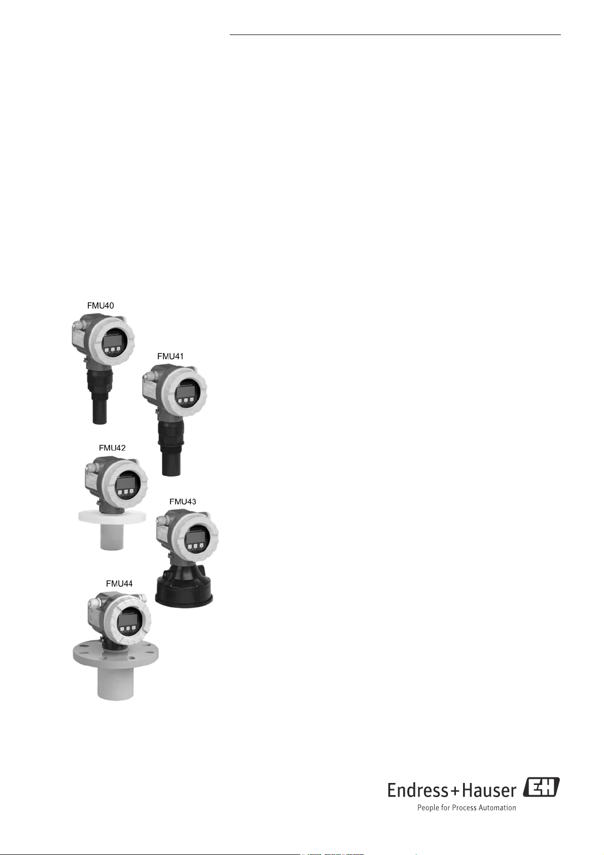
Prosonic M
FMU40, FMU41, FMU42,
FMU43, FMU44
Ultrasonic Level Measurement
Compact transmitters for non-contact level
measurement
Application
• Continuous, non-contact level measurement in fluids, pastes, sullages and coarse
bulk materials
• Flow measurement in open channels and measuring weirs
• System integration via:
– HART (standard), 4 to 20mA
–PROFIBUS PA
–FOUNDATION Fieldbus
• Maximum measuring range:
– FMU40: 5 m (16 ft) in fluids, 2 m (6.6 ft) in bulk materials
– FMU41: 8 m (26 ft) in fluids, 3,5 m (11 ft) in bulk materials
– FMU42: 10 m (33 ft) in fluids, 5 m (16 ft) in bulk materials
– FMU43: 15 m (49 ft) in fluids, 7 m (23 ft) in bulk materials
– FMU44: 20 m (66 ft) in fluids, 10 m (33 ft) in bulk materials
Features and benefits
• Quick and simple commissioning via menu-guided on-site operation with four-line,
multilingual plain text display
• Envelope curves on the on-site display for simple diagnosis
• Easy remote operation, diagnosis and measuring point documentation with the free
operating program FieldCare supplied.
• Suitable for explosion hazardous areas
(Gas-Ex, Dust-Ex)
• Linearization function (up to 32 points) for conversion of the measured value into
any unit of length, volume or flow rate
• Non-contact measurement method minimizes service requirements
• Optional remote display and operation (up to 20 m (66 ft) from transmitter)
• Installation possible from thread G 1½“ or 1½“ NPT upwards
• Integrated temperature sensor for automatic correction of the temperature
dependent sound velocity
Page 2

Table of contents
Prosonic M
Function and system design . . . . . . . . . . . . . . . . . . . . . .3
Measuring principle . . . . . . . . . . . . . . . . . . . . . . . . . . . . . . . . . . . 3
Equipment architecture . . . . . . . . . . . . . . . . . . . . . . . . . . . . . . . . 4
Input . . . . . . . . . . . . . . . . . . . . . . . . . . . . . . . . . . . . . . . . . .9
Measured variable . . . . . . . . . . . . . . . . . . . . . . . . . . . . . . . . . . . . . 9
Measuring range . . . . . . . . . . . . . . . . . . . . . . . . . . . . . . . . . . . . . . 9
Operating frequency . . . . . . . . . . . . . . . . . . . . . . . . . . . . . . . . . . 10
Output . . . . . . . . . . . . . . . . . . . . . . . . . . . . . . . . . . . . . . . 11
Output signal . . . . . . . . . . . . . . . . . . . . . . . . . . . . . . . . . . . . . . . . 11
Signal on alarm . . . . . . . . . . . . . . . . . . . . . . . . . . . . . . . . . . . . . . 11
Load HART . . . . . . . . . . . . . . . . . . . . . . . . . . . . . . . . . . . . . . . . . . 11
Output damping . . . . . . . . . . . . . . . . . . . . . . . . . . . . . . . . . . . . . . 11
Linearization . . . . . . . . . . . . . . . . . . . . . . . . . . . . . . . . . . . . . . . . 11
Power supply . . . . . . . . . . . . . . . . . . . . . . . . . . . . . . . . . 12
Terminal compartment . . . . . . . . . . . . . . . . . . . . . . . . . . . . . . . . 12
Terminal assignment . . . . . . . . . . . . . . . . . . . . . . . . . . . . . . . . . 12
Fieldbus plug connectors . . . . . . . . . . . . . . . . . . . . . . . . . . . . . . 13
Supply voltage . . . . . . . . . . . . . . . . . . . . . . . . . . . . . . . . . . . . . . . 13
Terminals . . . . . . . . . . . . . . . . . . . . . . . . . . . . . . . . . . . . . . . . . . . 14
Cable entry . . . . . . . . . . . . . . . . . . . . . . . . . . . . . . . . . . . . . . . . . . 14
Power consumption . . . . . . . . . . . . . . . . . . . . . . . . . . . . . . . . . . . 14
Current consumption (2 wire instruments) . . . . . . . . . . . . . . 14
HART ripple . . . . . . . . . . . . . . . . . . . . . . . . . . . . . . . . . . . . . . . . . 14
Max. noise HART . . . . . . . . . . . . . . . . . . . . . . . . . . . . . . . . . . . . . 14
Galvanic isolation . . . . . . . . . . . . . . . . . . . . . . . . . . . . . . . . . . . . 15
Performance characteristics . . . . . . . . . . . . . . . . . . . . 15
Reaction time . . . . . . . . . . . . . . . . . . . . . . . . . . . . . . . . . . . . . . . . 15
Reference operating conditions . . . . . . . . . . . . . . . . . . . . . . . . . 15
Measured value resolution . . . . . . . . . . . . . . . . . . . . . . . . . . . . . 15
Pulse frequency . . . . . . . . . . . . . . . . . . . . . . . . . . . . . . . . . . . . . . 15
Maximum measuring error . . . . . . . . . . . . . . . . . . . . . . . . . . . . 15
Typical measuring error
Influence of the vapor pressure . . . . . . . . . . . . . . . . . . . . . . . . . 16
. . . . . . . . . . . . . . . . . . . . . . . . . . . . . . 15
Installation . . . . . . . . . . . . . . . . . . . . . . . . . . . . . . . . . . . 16
Installation variants FMU40, FMU41 . . . . . . . . . . . . . . . . . . . . 16
Installation variants FMU42, FMU44 . . . . . . . . . . . . . . . . . . . . 17
Installation variants FMU43 . . . . . . . . . . . . . . . . . . . . . . . . . . . 17
Installation conditions for level measurements . . . . . . . . . . . . 17
Installation in narrow shafts . . . . . . . . . . . . . . . . . . . . . . . . . . . 18
Installation conditions for flow measurements . . . . . . . . . . . . 18
Blocking distance, nozzle installation . . . . . . . . . . . . . . . . . . . . 20
Environment . . . . . . . . . . . . . . . . . . . . . . . . . . . . . . . . . 21
Ambient temperature . . . . . . . . . . . . . . . . . . . . . . . . . . . . . . . . . 21
Storage temperature . . . . . . . . . . . . . . . . . . . . . . . . . . . . . . . . . . 21
Resistance to alternating temperature cycles . . . . . . . . . . . . . 21
Climate class . . . . . . . . . . . . . . . . . . . . . . . . . . . . . . . . . . . . . . . . . 21
Ingress protection . . . . . . . . . . . . . . . . . . . . . . . . . . . . . . . . . . . . 21
Vibration resistance . . . . . . . . . . . . . . . . . . . . . . . . . . . . . . . . . . 21
Electromagnetic compatibility (EMC) . . . . . . . . . . . . . . . . . . . . 21
Process . . . . . . . . . . . . . . . . . . . . . . . . . . . . . . . . . . . . . . 21
Process temperature . . . . . . . . . . . . . . . . . . . . . . . . . . . . . . . . . . 21
Process pressure . . . . . . . . . . . . . . . . . . . . . . . . . . . . . . . . . . . . . 21
Mechanical construction . . . . . . . . . . . . . . . . . . . . . . . 22
Design; dimensions . . . . . . . . . . . . . . . . . . . . . . . . . . . . . . . . . . . 22
Weight . . . . . . . . . . . . . . . . . . . . . . . . . . . . . . . . . . . . . . . . . . . . . 24
Housing design . . . . . . . . . . . . . . . . . . . . . . . . . . . . . . . . . . . . . . 25
Process connection . . . . . . . . . . . . . . . . . . . . . . . . . . . . . . . . . . . 25
Material (not in contact with process) . . . . . . . . . . . . . . . . . . . 26
Material (in contact with process) . . . . . . . . . . . . . . . . . . . . . . 27
Operability . . . . . . . . . . . . . . . . . . . . . . . . . . . . . . . . . . . 28
Display and operating elements . . . . . . . . . . . . . . . . . . . . . . . . 28
On-site operation . . . . . . . . . . . . . . . . . . . . . . . . . . . . . . . . . . . . . 29
Remote operation . . . . . . . . . . . . . . . . . . . . . . . . . . . . . . . . . . . . 29
Certificates and Approvals. . . . . . . . . . . . . . . . . . . . . . 31
CE mark . . . . . . . . . . . . . . . . . . . . . . . . . . . . . . . . . . . . . . . . . . . . 31
Ex approval . . . . . . . . . . . . . . . . . . . . . . . . . . . . . . . . . . . . . . . . . . 31
External standards and guidelines . . . . . . . . . . . . . . . . . . . . . . 31
Ordering information . . . . . . . . . . . . . . . . . . . . . . . . . . 32
Product structure FMU40 . . . . . . . . . . . . . . . . . . . . . . . . . . . . . . 32
Product structure FMU41 . . . . . . . . . . . . . . . . . . . . . . . . . . . . . . 34
Product structure FMU42 . . . . . . . . . . . . . . . . . . . . . . . . . . . . . . 36
Product structure FMU43 . . . . . . . . . . . . . . . . . . . . . . . . . . . . . . 38
Product structure FMU44 . . . . . . . . . . . . . . . . . . . . . . . . . . . . . . 39
3-point linearity protocol . . . . . . . . . . . . . . . . . . . . . . . . . . . . . . 41
5-point linearity protocol . . . . . . . . . . . . . . . . . . . . . . . . . . . . . . 42
Scope of delivery . . . . . . . . . . . . . . . . . . . . . . . . . . . . . . . . . . . . . 42
Accessories . . . . . . . . . . . . . . . . . . . . . . . . . . . . . . . . . . . 43
Weather protection cover . . . . . . . . . . . . . . . . . . . . . . . . . . . . . . 43
Installation bracket for FMU40, FMU41 . . . . . . . . . . . . . . . . . 43
Screw in flange . . . . . . . . . . . . . . . . . . . . . . . . . . . . . . . . . . . . . . . 44
Cantilever with mounting frame or wall bracket . . . . . . . . . . . 45
Commubox FXA195 HART . . . . . . . . . . . . . . . . . . . . . . . . . . . . 47
Commubox FXA291 . . . . . . . . . . . . . . . . . . . . . . . . . . . . . . . . . . 47
ToF Adapter FXA291 . . . . . . . . . . . . . . . . . . . . . . . . . . . . . . . . . 47
Remote display FHX40 . . . . . . . . . . . . . . . . . . . . . . . . . . . . . . . 47
Documentation . . . . . . . . . . . . . . . . . . . . . . . . . . . . . . . 51
Operating manual . . . . . . . . . . . . . . . . . . . . . . . . . . . . . . . . . . . . 51
Description of device functions . . . . . . . . . . . . . . . . . . . . . . . . . 51
Short instructions . . . . . . . . . . . . . . . . . . . . . . . . . . . . . . . . . . . . 51
Safety Instructions ATEX . . . . . . . . . . . . . . . . . . . . . . . . . . . . . . 52
Safety Instructions NEPSI . . . . . . . . . . . . . . . . . . . . . . . . . . . . . . 53
Safety Instructions
INMETRO . . . . . . . . . . . . . . . . . . . . . . . . . . . . . . . . . . . . . . . . . . . 54
Control drawings Installation drawings . . . . . . . . . . . . . . . . . . 55
2 Endress+Hauser
Page 3
Prosonic M
20 mA
100%
4 mA
0%
D
L
F
E
BD
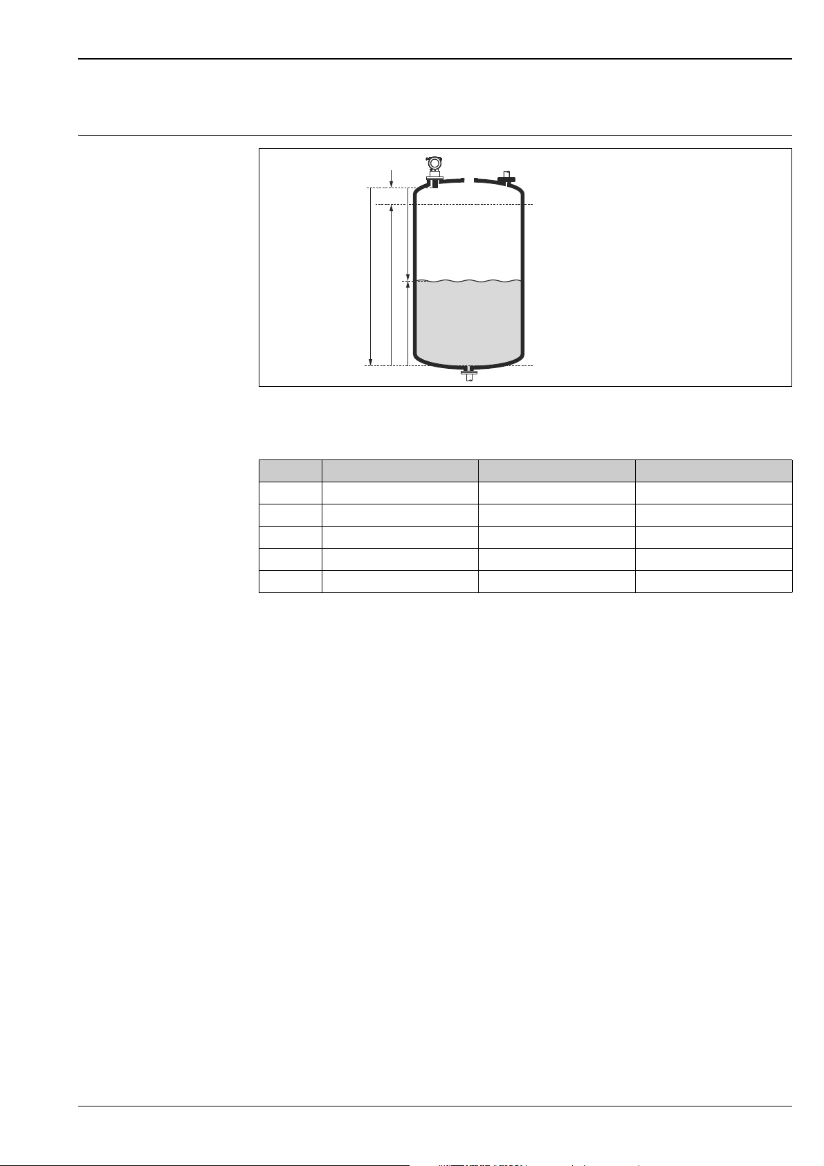
Measuring principle
Function and system design
BD Blocking distance D Distance from sensor membrane - product surface
E Empty distance F Span (full distance)
L Level
A0019264
Sensor BD Max. range fluids Max. range bulk materials
FMU40 0.25 (0.8) 5 (16) 2 (6.6)
FMU41 0.35 (1.1) 8 (26) 3.5 (11)
FMU42 0.4 (1.3) 10 (33) 5 (16)
FMU43 0.6 (2.0) 15 (49) 7 (23)
FMU44 0.5 (1.6) 20 (66) 10 (33)
Dimensions m (ft)
Time-of-flight method
The sensor of the Prosonic M transmits ultrasonic pulses in the direction of the product surface. There,
they are reflected back and received by the sensor. The Prosonic M measures the time t between pulse
transmission and reception. The instrument uses the time t (and the velocity of sound c) to calculate
the distance D between the sensor membrane and the product surface:
D = c t/2
As the device knows the empty distance E from a user entry, it can calculate the level as follows:
L = E - D
An integrated temperature sensor (NTC) compensates for changes in the velocity of sound caused by
temperature changes.
Interference echo suppression
The interference echo suppression feature on the Prosonic M ensures that interference echos (e.g.
from edges, welded joints and installations) are not interpreted as a level echo.
Calibration
Enter the empty distance E and the span F to calibrate the device.
Blocking distance
Span F may not extend into the blocking distance BD. Level echos within the blocking distance cannot
be evaluated due to the transient characteristics of the sensor.
Endress+Hauser 3
Page 4
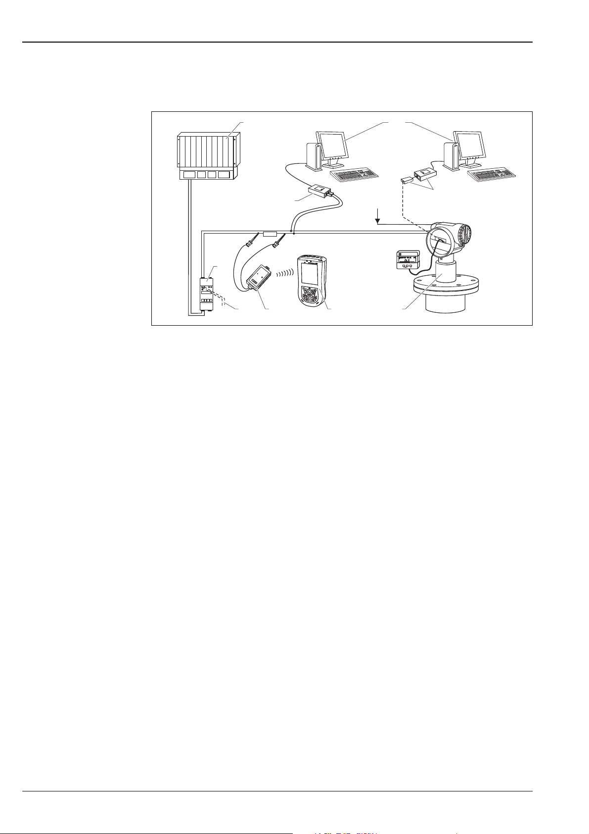
Equipment architecture 4…20 mA output with HART protocol
ENDRESS + HAUSER
E
+–
%
ENDRESS + HAUSER
RMA422
2
4
6789
10
5
1
3
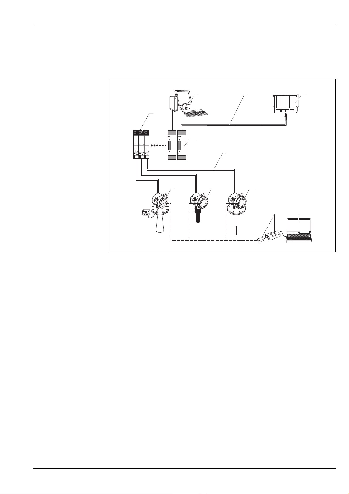
The complete measuring system consists of:
Prosonic M
A0019266
1 PLC (programmable logic controller)
2 Commubox FXA191 (RS232) or FXA195 (USB)
3 Computer with operating tool (e.g. FieldCare)
4 Commubox FXA291 with ToF Adapter FXA291
5 Power supply (for 4-wire)
6 Prosonic with display and operating modul
7 Field Xpert
8 VIATOR Bluetooth modem with connection cable
9 Connection for Commubox FXA191, FXA195 or Field Xpert
10 Transmitter supply unit RMA422 or RN221N (communication resistor included)
If the HART communication resistor is not built into the supply unit, it is necessary to insert a
communication resistor of 250 into the 2-wire line.
On-site operation
• With display and operating module,
• With a Personal Computer, FXA291 with ToF Adapter FXA291 (USB) and the operating software
"FieldCare". FieldCare is a graphical operating software for instruments (radar, ultrasonic, guided
microimpulse). It assists with commissioning, securing data, signal analysis and documentation of
the measuring point.
Remote operation
•With Field Xpert
• With a Personal Computer, Commubox FXA195 and the operating software "FieldCare"
4 Endress+Hauser
Page 5
Prosonic M
ENDRESS + HAUSERENDRESS + HAUSER
T
1 3
211
10
4
5
6
7
89
ENDRESS + HAUSER
E+–
%
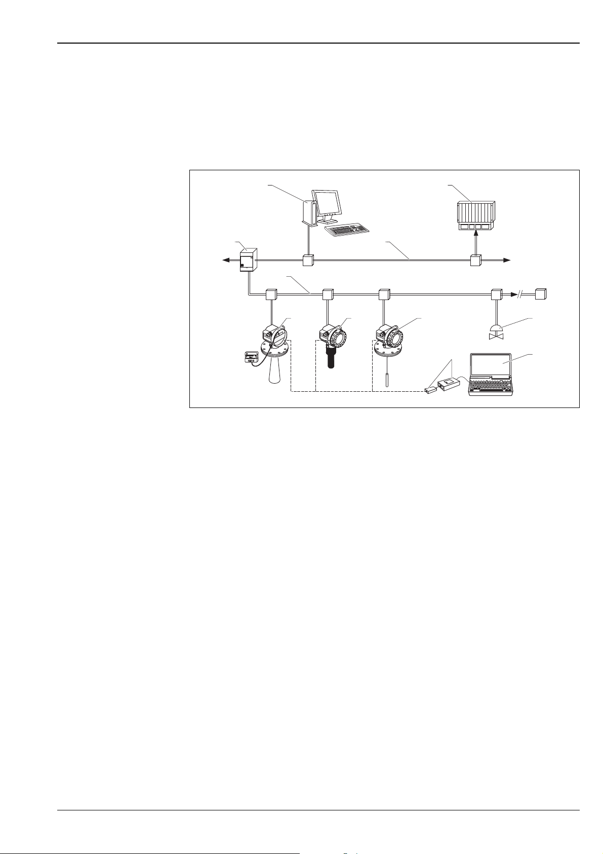
System integration using PROFIBUS PA
A maximum of 32 transmitters (8 if mounted in an explosion hazardous location Ex ia IIC according to
FISCO-model) can be connected to the bus.The segment coupler provides the operating voltage to the
bus. Both on-site as well as remote operation are possible. For further information on the cable
specifications, see Operating Instructions BA00034S/04/ENGuidelines for planning and
commissioning PROFIBUS DP/PA", PNO Guideline 2.092 "PROFIBUS PA User and Installation
Guideline" and IEC61158-2 (MBP).
1 Computer with Profiboard/Proficard and operating tool (FieldCare)
2PROFIBUS DP
3 PLC (programmable logic controller)
4 More functions (valves etc.)
5 Computer with operating tool (FieldCare)
6 Commubox FXA291 with ToF Adapter FXA291
7 Levelflex M
8Prosonic M
9 Micropilot M with display and operating modul
10 PROFIBUS PA
11 Segment coupler
A0019308
Endress+Hauser 5
Page 6

Prosonic M
T
T
15
13
14
1
6
5
7
11
12
3
4
8910
2
System integration using FOUNDATION Fieldbus
A maximum of 32 transmitters (standard or Ex d) can be connected to the bus. For protection class
Ex ia: the maximum number of transmitters depends on the established rules and standards for
intrinsically safe circuits (EN 60070-14) and proof of instrinsic safety. Both on-site and remote
operation are possible.
A0019309
1 SPS, PLC, API
2 Personal computer, e.g. with NI-FBUS configurator
3 VIATOR Bluetooth modem with connection cable
4 Field Xpert
5 More functions (valves etc.)
6 FieldCare
7 Commubox FXA291 with ToF Adapter FXA291
8 Levelflex M
9Prosonic M
10 Micropilot M
11 Power conditioner
12 Power supply
13 FF link
14 FOUNDATION Fieldbus
15 Ethernet
6 Endress+Hauser
Page 7
Prosonic M
FXN 671
mA1
+
FXN 671
mA1
+
FXN 671
mA1
+
ENDRESS + HAUSER
E+–
%
3
9
2
4
1
7
1011
8
5
6
System integration using Endress+Hauser Rackbus
You can interconnect a maximum of 64 2-wire devices with HART protocol to a Rackbus. Use an
FXN672 interface module for each device. You can integrate this bus into a higher-level bus by using
gateway.
A0019307
1 Interface FXN672
2 Personal computer with communication software
3Bus
4PLC
5 Gateway to MODBUS, FIP, PROFIBUS, INTERBUS etc.
6 4-20 mA HART
7 FieldCare
8 Commubox FXA291 with ToF Adapter FXA291
9 Levelflex M
10 Prosonic M
11 Micropilot M with display and operating modul
Note!
The FXN672 can be used with all 2-wire devices of the Prosonic M family.
Endress+Hauser 7
Page 8

Prosonic M
-
ENDRESS+HAUSER
RN 221N
ENDRESS+HAUSER
RN 221N
.
20...45 V
DC
FXN 520
FXN 520
1
12
System integration via Fieldgate
Vendor Managed Inventory
By using Fieldgates to interrogate tank or silo levels remotely, suppliers of raw materials can provide
their regular customers with information about the current supplies at any time and, for example,
account for them in their own production planning. For their part, the Fieldgates monitor the
configured level limits and, if required, automatically activate the next supply. The spectrum of options
here ranges from a simple purchasing requisition via e-mail through to fully automatic order
administration by coupling XML data into the planning systems on both sides.
Remote maintenance of measuring equipment
Fieldgates not only transfer the current measured values, they also alert the responsible standby
personnel, if required, via e-mail or SMS. In the event of an alarm or also when performing routine
checks, service technicians can diagnose and configure connected HART devices remotely. All that is
required for this is the corresponding HART operating software (e.g. FieldCare) for the connected
device. Fieldgate passes on the information transparently, so that all options for the respective
operating software are available remotely. Some on-site service operations can be avoided by using
remote diagnosis and remote configuration and all others can at least be better planned and prepared.
The complete measuring system consists of devices and:
1 Fieldgate FXA520
2 Multidrop Connector FXN520
Note!
The number of instruments which can be connected in mutidrop mode can be calculated by the
"FieldNetCalc" program. A description of this program can be found in Technical Information
TI00400F/00/EN (Multidrop Conncector FXN520).
The program is available form your Endress+Hauser sales organisation or in the internet at:
"www.endress.com select your country download search: Fieldnetcalc
8 Endress+Hauser
A0019306
Page 9
Prosonic M
Input
Measured variable The distance D between the sensor membrane and the product surface is measured.
Using the linearization function, the device uses D to calculate:
•level L in any units
• volume V in any units
• Flow Q across measuring weirs or open channels in any units
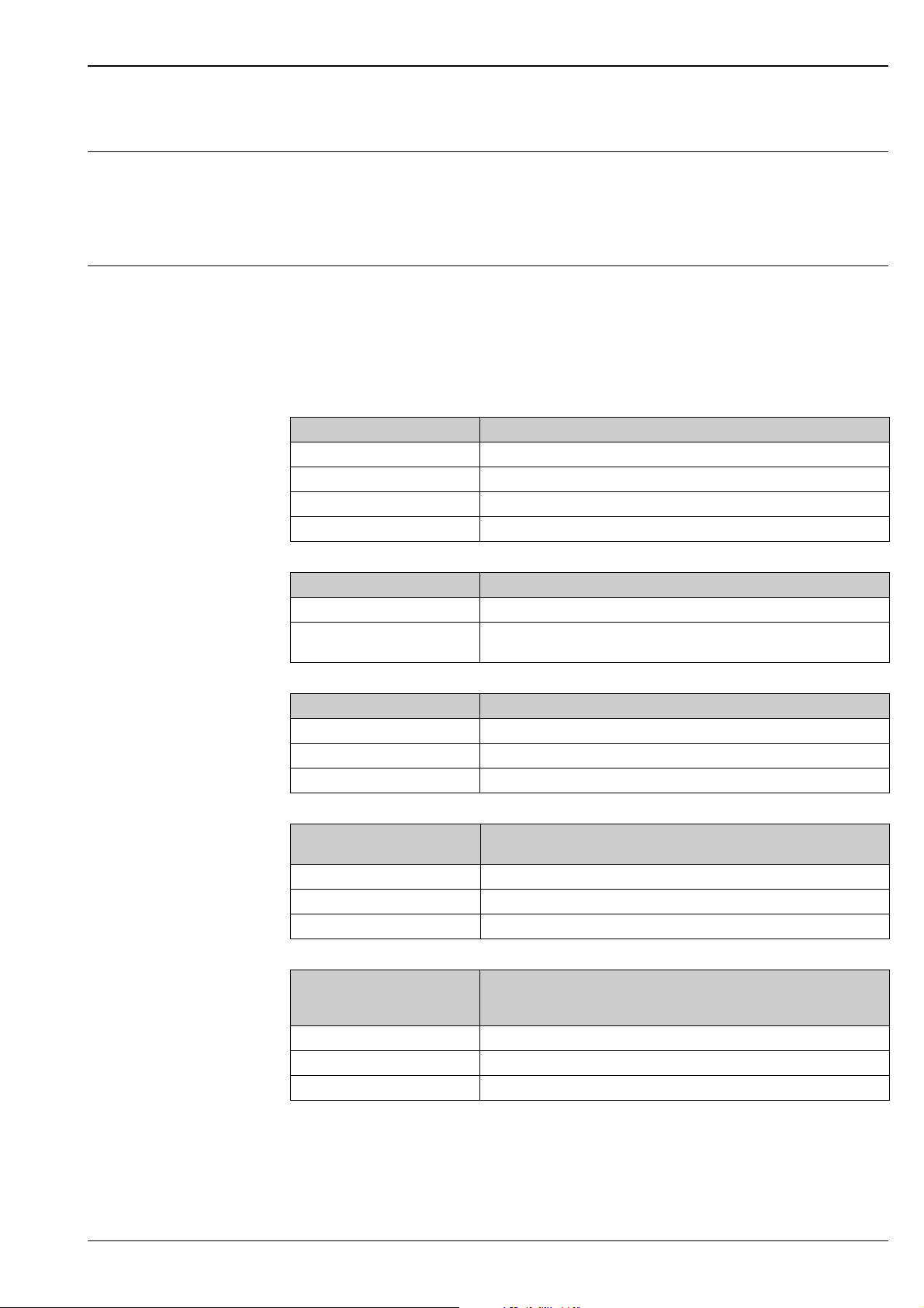
Measuring range The measuring range is limited by the range of a sensor. The sensor range is, in turn, dependent on the
operating conditions. To estimate the actual range, proceed as follows (see also the calculation
example in the diagram):
1. Determine which of the influences shown in the following table are appropriate for your process.
2. Add the corresponding attenuation values.
3. From the total attenuation, use the diagram to calculate the range.
Fluid surface Attenuation
Calm 0 dB
Waves 5 to 10 dB
Strong turbulence (e.g. stirrers) 10 to 20 dB
Foaming Please contact your Endress+Hauser sales representative.
Bulk material surface Attenuation
Hard, rough (e.g. rubble) 40 dB
Soft (e.g. peat, dust-covered
clinker)
Dust Attenuation
No dust formation 0 dB
Little dust formation 5 dB
Heavy dust formation 5 to 20 dB
Filling curtain in detection
range
None 0 dB
Small quantities 5 to 10 dB
Large quantities 10 to 40 dB
Temperature difference
between sensor and product
surface
to 20 °C (68 °F) 0 dB
to 40 °C (104 °F) 5 to 10 dB
to 80 °C (176 °F) 10 to 20 dB
40 to 60 dB
Attenuation
Attenuation
Endress+Hauser 9
Page 10
Prosonic M
10 20 304050 607080
1
2
3
4
5
6
7
8
9
10
11
12
13
14
15
16
17
18
19
20
FMU44
A [dB]
R [m]
0
FMU43
FMU42
FMU41
FMU40
AAttenuation (dB)
RRange (m)
Example (for FMU43)
For typical solid applications, a certain amount of dust coverage is normally present. Therefore, the
following range results from the table and the diagram:
Operating frequency
• Dust-covered rubble approx. 50 dB
• No dust formation 0 dB
• No filling curtain in
detection range 0 dB
• Temperature diff. < 20°C 0 dB
approx. 50 dB range approx. 7 m (23 ft)
These measuring conditions have been taken into account during the calculation of the maximum
measuring range in solid applications.
Sensor Operating frequency
FMU40 approx. 70 kHz
FMU41 approx. 50 kHz
FMU42 approx. 42 kHz
FMU43 approx. 35 kHz
FMU44 approx. 30 kHz
10 Endress+Hauser
A0019268
Page 11

Prosonic M
Output
Output signal According to the instrument version ordered:
• 4…20 mA with HART protocol
•PROFIBUS PA
• FOUNDATION Fieldbus
Signal on alarm Error information can be accessed via the following interfaces:
• On-site display (error symbol, error code and plain text description)
• Current output, signal on error can be selected (e.g. according to NAMUR recommendation NE43)
• Digital interface
Load HART Minimum load for HART communication: 250
Output damping Freely selectable, 0 to 255 s
Linearization The linearization function of the Prosonic M allows conversion of the measured value into any unit of
length or volume. In open channels or measuring weirs, also a flow linearization is possible (calculation
of the flow from the measured level). The linearization table for calculating the volume in an horizontal
cylindrical tank is preprogrammed. You can also enter any number of other tables containing up to 32
value pairs either manually or semi-automatically (by filling the vessel under controlled conditions).
The supplied FieldCare operating program can automatically calculate the table for any tank, weir or
flume and upload it into the device.
Flow curves for open channels can be calculated and entered into the instrument by the FieldCare as
well ( ä 29, "Operation with FieldCare").
Endress+Hauser 11
Page 12
Prosonic M
1
A
B
2
1
4
AB
3
3
1234 5 612
L- L+ I+ I-
I+ I-
L1/L+ N/L-
4
1
5
Power supply
Terminal compartment In the F12 housing, the terminals are located underneath the housing cover. In the T12 housing, they
are under the cover of the separate terminal compartment.
A0019271
A F12 housing
B T12 housing
1 Sealed terminal compartment
Terminal assignment
A0019268
A Loop-powered version 3 Plant ground
B 4-wire version (active) 4 4-20 mA HART
1Power 5Display unit, recorder, PCS
2 Test clamp for testing of the signal current
• Connect the connecting line to the screw terminals (line cross-sections of 0.5 to 2.5mm (20 to
14 AWG)) in the terminal compartment.
• Use 2-wire twisted pair cable with screen for the connection.
• Protective circuitry against reverse polarity, RFI and over-voltage peaks is built into the device (see
also Technical Information TI00241F/00/EN "EMC Test Procedures") ä 21, "Electromagnetic
compatibility (EMC)".
• A standard installation cable is sufficient if only the analogue signal is used. Use a screened cable
when working with a superimposed communication signal (HART).
12 Endress+Hauser
Page 13
Prosonic M
3
4
1
2
+–
3
1
2
3
4
1
2
+–
3
21
3
4
2
1
4
3
PROFIBUS PA
1T-Box
2PROFIBUS PA
3 Plant ground
A0019276
FOUNDATION Fieldbus
A0019275
The digital communication signal is transmitted to the bus via a 2-wire connection. The bus also
provides the auxiliary energy. Use 2-wire twisted pair cable with screen.
Refer to the following operating manuals for information on cable types, and how to set up and ground
the network:
• BA00034S "PROFIBUS DP/PA: "Guidelines for planning and commissioning PROFIBUS DP/PA", PNO
Guideline 2.092 "PROFIBUS PA User and Installation Guideline" and IEC61158-2 (MBP).
• BA00013S "FOUNDATION Fieldbus Overview", FONDATION Fieldbus Guideline and IEC61158-2
(MBP).
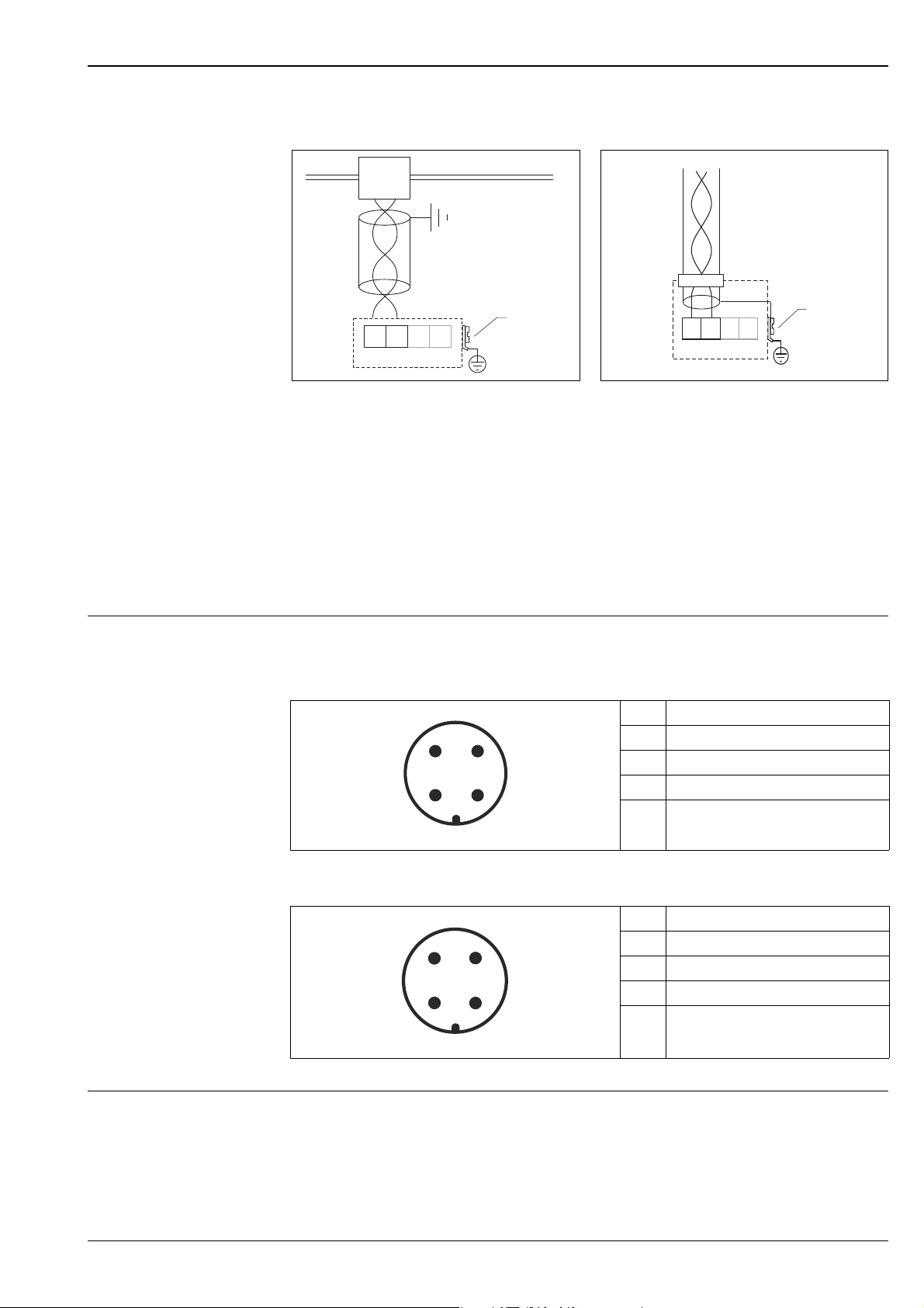
Fieldbus plug connectors For the versions with fieldbus plug connector (M12 or 7/8"), the signal line can be connected without
opening the housing.
Pin assignment of the M12 plug connector (PROFIBUS PA plug)
Pin Meaning
1Signal +
2not connected
3Signal -
4Ground
A0011175
Pin assignment of the 7/8" plug connector (FOUNDATION Fieldbus plug)
Pin Meaning
1Signal -
2Signal +
3Shield
4Not connected
A0011176
Supply voltage HART, 2-wire
The following values are the voltages across the terminals directly at the instrument:
Endress+Hauser 13
Page 14

Prosonic M
Version
Standard
2-wire HART
Fixed current,
adjustable, e.g. for
solar power
operation
(measured value
via HART)
Fixed current for
HART multidrop
mode
1) Start-up current 11 mA
Ex ia
Ex d
Standard 11 mA 10 V 36 V
Ex ia 11 mA 10 V 30 V
Standard 4 mA
Ex ia 4 mA
Current
consumption
4 mA 14 V 36 V
20 mA 8 V 36 V
4 mA 14 V 30 V
20 mA 8 V 30 V
4 mA 14 V 30 V
20 mA 11 V 30 V
1)
1
Terminal voltage
minimum
14 V 36 V
14 V 30 V
HART, 4-wire, active
Version Voltage Max. load
DC 10.5 to 32 V 600
AC 50/60 Hz 90 to 253 V 600
Terminal voltage
maximum
Terminals Cable cross-section: 0.5 to 2.5 mm2 (20 to 14 AWG)
Cable entry • Cable gland: M20x1.5 (recommended cable diameter 6 to 10 mm (0.24 to 0.39 in))
• Cable entry G ½" or NPT ½"
• PROFIBUS PA M12 plug
• FOUNDATION Fieldbus 7/8" plug
Power consumption
Current consumption (2 wire instruments)
Version Power consumption
2-wire 51 mW to 800 mW
4-wire AC max. 4VA
4-wire DC; FMU40/41 330 mW to 830 mW
4-wire DC; FMU42/43 600 mW to 1 W
Communication Current consumption
HART 3.6 to 22 mA
PROFIBUS PA max. 13 mA
FOUNDATION Fieldbus max. 15 mA
HART ripple 47 to 125 Hz: Vpp = 200 mV (measured at 500 )
Max. noise HART 500 Hz to 10 kHz: Vrms = 2.2 mV (measured at 500 )
14 Endress+Hauser
Page 15

Prosonic M
Galvanic isolation With 4-wire devices, the evaluation electronics and mains voltage are galvanically isolated from each
other.
Performance characteristics
Reaction time The reaction time depends on the parameter settings. The minimum values are:
• 2-wire devices (FMU40/41/42): min. 2 s
• 2-wire diveces (FMU43 - PROFIBUS PA or FOUNDATION Fieldbus): min. 2 s
• 2-wire devices (FMU44): min. 3 s
• 4-wire devices (FMU40/41/42/43/44): 0.5 s
Reference operating conditions
• Temperature = +20 °C (+68 °F)
• Pressure = 1013 mbar abs. (15 psi abs.)
• Humidity = 50 %
• Ideal reflective surface (e.g. calm, smooth fluid surface)
• No interference reflections within signal beam
• Set application parameters:
– Tank shape = dome ceiling
– Medium property = liquid
– Process conditions = standard liquid
Measured value resolution
Sensor Measured value resolution
FMU40 1 mm (0.04 in)
FMU41 1 mm (0.04 in)
FMU42 2 mm (0.08 in)
FMU43 2 mm (0.08 in)
FMU44 2 mm (0.08 in)
Pulse frequency • 2-wire devices (FMU40/41/42): max. 0.5Hz
• 2-wire devices (FMU43 - PROFIBUS PA or FOUNDATION Fieldbus): max. 0.5 Hz
• 2-wire devices (FMU44): max. 0.3 Hz
• 4-wire devices (FMU40/41/42/43/44): max. 2Hz
The exact values are dependent on the type of device and the parameter settings.
1)
Maximum measuring error
Typical measuring error
2)±0.2 % of the maximum span of the sensor
Include linearity, repeatability and hysteresis
Better than:
Sensor Measuring error
FMU40 ±2 mm (0.08 in) or 0.2 % of measuring distance
FMU41 ±2 mm (0.08 in) or 0.2 % of measuring distance
FMU42 ±4 mm (0.16 in) or 0.2 % of measuring distance
FMU43 ±4 mm (0.16 in) or 0.2 % of measuring distance
FMU44 ±4 mm (0.16 in) or 0.2 % of measuring distance
* whichever is greater
1) according to EN 61298-2
2) with reference operating conditions
*
*
*
*
*
Endress+Hauser 15
Page 16
Prosonic M
ENDRESS+HAUSER
Prosonic M
ENDRESS+HAUSER
Prosonic M
AB
C
D
1
1
1
2
3
4
Influence of the vapor pressure
Installation variants FMU40, FMU41
The vapor pressure at 20 °C (68 °F) gives a hint on the accuracy of the ultrasonic level measurement. If
the vapor pressure at 20 °C (68 °F) is below 50 mbar (1 psi), ultrasonic level measurement is possible
with a very high accuracy. This is valid for water, aqueous solutions, water-solid-solutions, dilute acids
(hydrochloric acid, sulfuric acid, ...), dilute bases (caustic soda, ...), oils, greases, slurries, pastes, ...
High vapor pressures or outgassing media (ethanol, acetone, ammonia, ...) can influence the accuracy.
If conditions like these are present, please contact your Endress+Hauser sales representative.
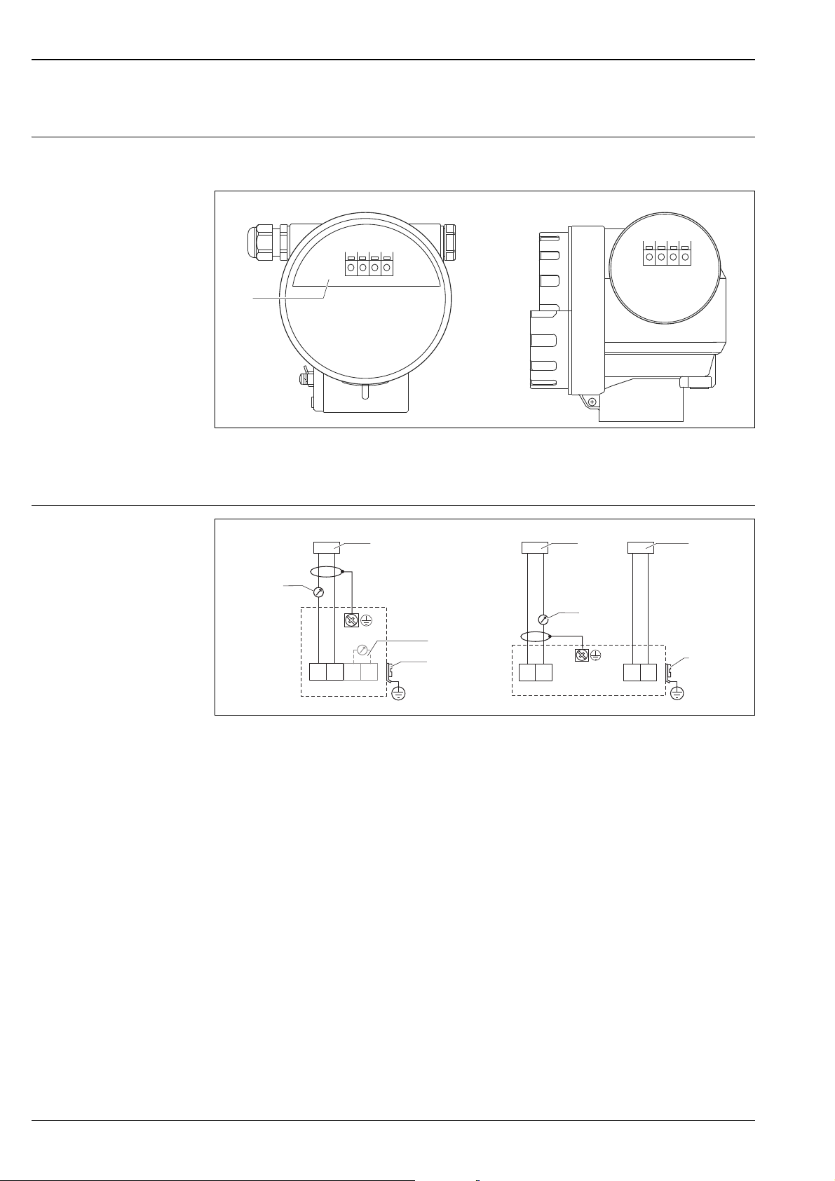
Installation
A Installation with counter nut
1 Counter nut (PC) supplied for G 1½" and G 2" instruments
B Installation with sleeve
1 Sealing (EPDM) supplied
C Installation with installation bracket
D Installation with screw in flange
1 Sealing (EPDM) supplied
2Nozzle
3Sensor
4Screw in flange
For installation bracket or adapter flange ä 43, "Accessories".
16 Endress+Hauser
A0019052
Page 17
Prosonic M
AB
-
.
ENDRESS+HAUSER
ProsonicM
1
3
2
A
B
-
.
234
1/6D
D
1
5
6
L
r
7
Installation variants FMU42, FMU44
Installation variants FMU43
A Installation with universal flange (Ex-hazardous, e.g. Zone 20)
B Installation with mounting bracket (Non-Ex-hazardous, Zone 20)
A0019280
A Installation with universal slip-on flange (option), (Ex-hazardous, e.g. Zone 20)
1Sensor
2Nozzle
3 Slip-on flange
B Installation with mounting bracket (Non-Ex-hazardous, Zone 20)
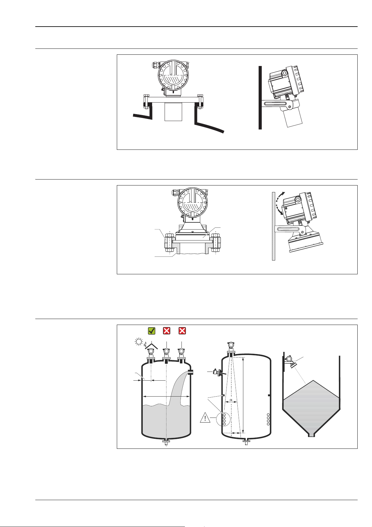
Installation conditions for level measurements
• Do not install the sensor in the middle of the tank (3). We recommend leaving a distance between
• Use a protective cover, in order to protect the device from direct sun or rain (2) ä 43, "Weather
the sensor and the tank wall (1) measuring 1/6 of the tank diameter.
protection cover".
A0019053
A0019278
Endress+Hauser 17
Page 18

Prosonic M
1
• Avoid measurements through the filling curtain (4).
• Make sure that equipment (5) such as limit switches, temperature sensors, etc. are not located
within the emitting angle . In particular, symmetrical equipment (6) such as heating coils, baffles
etc. can influence measurement.
• Align the sensor so that it is vertical to the product surface (7).
• Never install two ultrasonic measuring devices in a tank, as the two signals may affect each other.
• To estimate the detection range, use the 3 dB emitting angle .
Installation in narrow shafts
Sensor L
FMU40 11° 5 (16) 0.48 (1.6)
FMU41 11° 8 (26) 0.77 (2.5)
FMU42 9° 10 (33) 0.79 (2.6)
FMU43 6° 15 (49) 0.79 (2.6)
FMU44 11 ° 20 (66) 1.93 (6.3)
m (ft)
max
r
max
In narrow shafts with strong interference echoes,
we recommend using an ultrasound guide pipe
(e.g. PE or PVC wastewater pipe) with a minimum
diameter of 100 mm (3.94 in).
Make sure that the pipe is not soiled by accumulated dirt. If necessary, clean the pipe at regular
intervals.
1Venting hole
A0019310
Installation conditions for flow measurements
• Install the Prosonic M at the inflow side, as close above the maximum water level H
as possible
max
(take into account the blocking distance BD).
• Position the Prosonic M in the middle of the channel or weir.
• Align the sensor membrane parallel to the water surface.
• Keep to the installation distance of the channel or weir.
• You can enter the "Flow to Level" linearization curve ("Q/h curve") using FieldCare or manually via the
on-site display.
18 Endress+Hauser
Page 19

Prosonic M
1 x b
0
b
0
BD
A
E
B C
V
H
max
=F
(= F)
min. 3 H
H
min. 2 H
a
min. 2 H
BD
E
max.
max.
max.
max.
Example: Khafagi-Venturi flume
A Khafagi-Venturi flume
B Inflow
C Outflow
BD Blocking distance
E Empty calibration
F Full calibration
V Direction of flow
A0019606
Example: Triangular weir
Endress+Hauser 19
BD Blocking distance
E Empty calibration
F Full calibration
A0019312
Page 20

Prosonic M
F
E
BD
SD
L
D
L
D
L
D
AB C
Blocking distance, nozzle installation
Install the Prosonic M at a height so that the blocking distance BD is not undershot, even at maximum
fill level. Use a pipe nozzle if you cannot maintain the blocking distance in any other way. The interior
of the nozzle must be smooth and may not contain any edges or welded joints. In particular, there
sh ould be no burr on t he in side of the tank side nozzle end. Note the specified limits for nozzle diameter
and length. To minimise disturbing factors, we recommend an angled socket edge (ideally 45°).
A0019311
A FMU40, FMU41
B FMU42, FMU44
C FMU43
BD Blocking distance F Full calibration (span)
SD Safety distance D Nozzle diameter
E Empty calibration L Nozzle length
Maximum nozzle length [mm (in)]
Nozzle diameter FMU40 FMU41 FMU42 FMU43 FMU44
DN50/2" 80 (3.15)
DN80/3" 240 (9.45) 240 (9.45) 250 (9.84)
DN100/4" 300 (11.8) 300 (11.8) 300 (11.8) 300 (11.8)
DN150/6" 400 (15.7) 400 (15.7) 400 (15.7) 300 (11.8) 400 (15.7)
DN200/8" 400 (15.7) 400 (15.7) 400 (15.7) 300 (11.8) 400 (15.7)
DN250/10" 400 (15.7) 400 (15.7) 400 (15.7) 300 (11.8) 400 (15.7)
DN300/12" 400 (15.7) 400 (15.7) 400 (15.7) 300 (11.8) 400 (15.7)
Sensor characteristics
Emitting angle 11° 11° 9° 6° 11°
Blocking distance [m (ft)] 0.25 (0.8) 0.35 (1.1) 0.4 (1.3) 0.6 (2.0) 0.5 (1.6)
Max. range [m (ft)]
in liquids
Max. range [m (ft)]
in solids
5 (16.0) 8 (26.0) 10 (33.0) 15 (49.0) 20 (66.0)
2 (6.6) 3.5 (11.0) 5 (16.0) 7 (23.0) 10 (33.0)
Caution!
If the blocking distance is undershot, it may cause device malfunction.
Note!
In order to notice if the level approaches the blocking distance, you can specify a safety distance (SD).
If the level is within this safety distance, the Prosonic M outputs a warning or alarm message.
20 Endress+Hauser
Page 21

Prosonic M
Environment
Ambient temperature – 40 °C to +80 °C (–40 °F to +176 °F)
The functionality of the LC display becomes restricted at Tu<–20 °C (Tu<–4 °F) and Tu>+60 °C
(Tu>140 °F).
If the device is operated outdoors in strong sunlight, you should use a protective cover ( ä 43).
Storage temperature –40 °C to +80 °C (–40 °F to +176 °F)
Resistance to alternating temperature cycles
Climate class DIN EN 60068-2-38 (Test Z/AD) DIN/IEC 68 T2-30Db
Ingress protection • With closed housing, tested according to
Vibration resistance DIN EN 60068-2-64 / IEC 68-2-64: 20…2000 Hz, 1 (m/s
Electromagnetic compatibility (EMC)
To DIN EN 60068-2-14; Nb test: +80°C/–40°C (+176 °F/–40 °F), 1K/min, 100cycles
– IP68, NEMA 6P (24h at 1.83 m (6 ft) under water surface)
– IP66, NEMA 4x
• With open housing: IP20, NEMA 1 (also ingress protection of the display)
Caution!
Degree of protection IP68 NEMA 6P applies for M12 PROFIBUS-PA plugs and for 7/8" FF plug only
when the cable is plugged in.
• Electromagnetic compatibility according to all relevant requirements of the EN 61326- series and
NAMUR recommendation EMC (NE21). For details see declaration of conformity.
• A standard installation cable is sufficient if only the analogue signal is used. Use a screened cable
when working with a superimposed communication signal (HART).
Process
Process temperature –40°C to +80 °C (–40 °F...+176 °F)
A temperature sensor is integrated in the sensor for correction of the temperature-dependent time-offlight.
)2
/Hz; 3 x 100 min
Process pressure • FMU40/41: 0.7 bar to 3bar abs. (10.15 psi...43.5 psi abs.)
• FMU42/43/44: 0.7 bar to 2.5bar abs. (10.15 psi...36.25 psi abs.)
Endress+Hauser 21
Page 22

Mechanical construction
65
(2.6)
78
(3.1)
ø129 (5.1)
~86 (3.4)
78
(3.1)
85
(3.3)
85
(3.3)
65
(2.6)
ø129 (5.1)
162 (6.4)
150 (5.9)
68
(2.7)
~148 (5.8)
~
83 (3.3)
22 (0.9)
CD
ø39 (1.5)
ø50 (2.0)
~
148 (5.8)
~87 (3.4)
22 (0.9)
ENDRESS+HAUSER
Prosonic M
ENDRESS+HAUSER
Prosonic M
32 (1.3)
AB
G 1½"
NPT 1½"
94
(3.7)
60 60
G 2"
NPT 2"
mm (in)
~110 (4.3)
ø70 (2.8)
~85 (3.3)
C
65
(2.6)
78
(3.1)
ø129 (5.1)
86
(3.4)
78
(3.1)
85 (3.3)
65
(2.6)
ø129 (5.1)
162 (6.4)
150 (5.9)
68
(2.7)
94
(3.7)
ENDRESS+HAUSER
Prosonic M
ENDRESS+HAUSER
Prosonic M
32 (1.3)
AB
D
ø98 (3.9)
07 (4.2)
~1
~145 (5.7)
85 (3.3)
mm (in)
Design; dimensions FMU40, FMU41
Prosonic M
A0019317
A F12 housing B T12 housing
C FMU40 D FMU41
FMU42, FMU44 with slip-on flange
A F12 housing B T12 housing
C FMU42 D FMU44
A0019318
22 Endress+Hauser
Page 23

Prosonic M
ENDR
ESS+HA
USER
Prosonic
M
75
(3.0)
119 (4.7)
105 (4.1)
A
ENDRESS+HA
USER
Prosonic
M
B
119 (4.7)
30 (1.2)
98 (3.9)
125 (4.9)
30 (1.2)
1 1
mm (in)
85 (3.3)
65
(2.6)
78
(3.1)
ø129 (5.1)
150 (5.9)
~248 (9.8)
E
N
D
RE
SS+
H
A
U
SE
R
Pro
son
ic
M
ø230 (9.1)
89 (3.5)
A
B
~86
(3.4)
mm (in)
75 (3.0)
158 (6.
2)
1
11 (0.43)
119 (4.68)
2 (0.08)
25 (0.98)
120 (4.7)
~123 (4.8)
40 (1.6) 40 (1.6)
mm (in)
FMU42, FMU44 with mounting bracket
A FMU42 ( T12, F12 housing) B FMU44 (T12, F12 housing)
1M8
FMU43
A0019322
A With slip-on flange (ANSI 4" DN 100) B With mounting bracket (F12 housing)
12xM8
Mounting bracket for FMU42, FMU43 and FMU44
Endress+Hauser 23
A0019337
A0019342
Page 24

Flanges for FMU42 and FMU44
G 2"
ISO228
20 (0.8)
C
E
A
B
D
mm (in)
Prosonic M
Weight
A0019343
suitable for A B C D E number of
boreholes
3" 150 lbs / DN80 PN16 / 10K 80 150 mm
(5.91")
4" 150 lbs / DN100 PN16 / 10K 100 175 mm
6" 150 lbs / DN150 PN16 / 10 K 150 240 mm
8" 150 lbs 298.5 mm
DN200 PN16 / 10 K 200 290 mm
Sensor Weight kg (lbs)
FMU40 approx. 2.5 (5.51)
FMU41 approx. 2.6 (5.73)
FMU42 approx. 3 (6.62)
FMU43 approx. 3.5 (7.72)
FMU44 approx. 4 (8.82)
(6.90")
(9.45")
(11.75")
(11.42")
160 mm
(6.30")
190.5 mm
(7.50")
241.3 mm
(9.50")
298.5 mm
(11.75")
295 mm
(11.61")
200 mm
(7.87")
228.6 mm
(9.00")
285 mm
(11.22")
342.9 mm
(13.50")
340 mm
(13.39")
19 mm
(0.75")
19 mm
(0.75")
23 mm
(0.91")
22. 5 mm
(0.89")
23 mm
(0.91")
45° 8
45° 8
45° 8
45° 8
30° 12
24 Endress+Hauser
Page 25

Prosonic M
Housing design Types of housings
• F12 housing with sealed terminal compartment for standard or Ex ia applications
• T12 housing with separate terminal compartment and explosionproof encapsulation
Material
Aluminium, powder-coated ( ä 26)
Cover
• Aluminium, for version without on-site display
• Inspection glass for version with on-site display. This version cannot be supplied together with the
ATEX II 1/2 D certificate.
Process connection
Sensor Process connection
FMU40 • Thread G 1½“
• Thread NPT 1½“ - 11.5
FMU41 • Thread 2"
•Thread NPT 2" - 11.5
FMU42 • Universal flange DN 80 PN16 / ANSI 3" 150 lbs / JIS 10K 80
• Universal flange DN 100 PN16 / ANSI 4" 150 lbs / JIS 10K 100
•Mounting bracket
FMU43 • Universal flange DN 100 / ANSI 4" / JIS16K100
•Mounting bracket
FMU44 • Universal flange DN 100 PN16 / ANSI 4" 150 lbs / JIS 10K 100
• Universal flange DN 150 PN16 / ANSI 6" 150 lbs / JIS 10K 150
• Universal flange DN200 PN16 / JIS 10K 200
• Flange ANSI 8" 150 lbs
•Mounting bracket
Endress+Hauser 25
Page 26

Prosonic M
AB
ENDRESS+HAUSER
IP 65
O
r
d
e
r
C
o
d
e
:
S
e
r
.
-N
o
.
:
M
e
s
s
b
e
r
e
ic
h
M
e
a
s
u
r
in
g
r
an
g
e
U
1
6
..
.
36
V
D
C
4
..
.2
0
m
A
m
ax
.
2
0
m
Mad
e
in Germany
Ma
ulburg
T
>
7
0
°
C
:
A
t
>
8
5°
C
Madein Germany
Maulburg
ENDRESS+HAUS
ER
IP 65
Order Code:
Ser.-No.:
Messbereich
Measuring r
ange
U 16...36
V DC
4...20
mA
max
. 20 m
Madein Germany
Maulburg
T
>70°C :
A
t >
8
5
°C
987
56
98
56
3
2
1
4
2
1
3
3
7
Material
T12 and F12 housing (powder-coated)
(not in contact with process)
A T12 housing
B F12 housing
Pos. Part Material
1 T12 and F12 housing AlSi10Mg
Cover (Display) AlSi10Mg
O-ring EPDM
2
Window ESG-K-Glass
Sealing of the glass Silicone sealing compound Gomastit 402
Cable gland Polyamid (PA), CuZn nickel-plated
O-Ring EPDM
3
Plug
PBT-GF30 or 1.0718 galvanized
PE or 3.1655
Adapter 316L (1.4435) or AlMgSiPb (anodized)
Cover (Connection compartment) AlSi10Mg
4
O-ring EPDM
Clamp Screw: A4; Clamp: CuZn nickel-plated; Spring washer: A4
5O-ring EPDM
Tag 304 (1.4301)
6
Rope VA
Crimp sleeve Aluminium
Nameplate 316L (1.4404)
7
Groove pin A4 (1.4571)
8Ground terminal
Screw: A2; Springwasher: A4; Clamp: 304 (1.4301)
Holder: 301 (1.4310)
9Screw A2-70
Note!
Seawater-resistant parts please order on request (complete in 316L (1.4404)).
A0019273
26 Endress+Hauser
Page 27

Prosonic M
1
2a
3
2a
3
1
1
6
5
9
7
2b
AB
CC
B
8
2a
4
2b
2a
Material (in contact with process)
A0019054
Pos. Part A
FMU40, FMU41BFMU42, FMU44
1 Sensor PVDF PVDF
2a Sealing EPDM EPDM or FKM EPDM
2b O-ring EPDM - EPDM
3Flange -
4 Counter nut PC - -
5Screws - - V2A
Thread insert for
6
mounting bracket
7 Sensor membrane - - 316 Ti (1.4571)
Mounting bracket (retainer)
8
Screws
Mounting bracket
9
Screws
1) Endress+Hauser supplies DIN/EN flanges made of stainless steel AISI 316L with the material number
1.4404 or 1.4435. With regard to their temperature stability properties, the materials 1.4404 and 1.4435
are grouped under 13E0 in EN 1092-1 Tab. 18. The chemical composition of the two materials can be identical.
--CuZn
-
-
-
-
PP, PVDF or stainless steel
316L (1.4435 or 1.4404)
316 Ti (1.4571)
V4A
316 Ti (1.4571)
V2A
C
FMU43
UP (Unsaturated
polyester resin)
PP or 316 Ti
1)
(1.4571)
316 Ti (1.4571)
V2A
-
-
Note!
The chemical compatibility of the sensors must be checked before installation with compatibility
charts.
Endress+Hauser 27
Page 28

Operability
ENDRESS + HAUSER
E
+
–
1
2
3
4
Prosonic M
Display and operating elements
The LCD module VU331 for display and operation is located beneath the housing cover. The measured
value is legible through the glass in the cover. Open the cover to operate the device.
A0019274
1 LCD liquid crystal display
2Snap fit
3Keys
4 Symbols
Symbol in display
continuous flashing
Meaning Alarm Warning Communication Security Locking
Function of the keys
Key(s) Meaning
Navigate upwards in the selection list
Edit numeric value within a function
Navigate downwards in the selection list
Edit numeric value within a function
Navigate to the left within a function group
Navigate to the right within a function group, confirmation.
Contrast settings of the LCD
Hardware lock / unlock
After a hardware lock, an operation of the instrument via display or
communication is not possible!
F
The hardware can only be unlocked via the display. An unlock parameter must
be entered to do so (unlock parameter: 100).
O
S
and S and
O
O
S
X
F
and
or
and
F
F
28 Endress+Hauser
Page 29

Prosonic M
X
X
X
X
S
S
O
O
FF
F
F
HOME
FG00
F000 F001 F002 F003 F004 ...
FG01
FG02
FG03
FG04
FG05
FG06
FG07
...
ENDRESS + HAUSER
E
+–
Headline Position indicator
Main value
Unit
Symbol
Selection list
Function groups -> Functions
Help text
Envelope
curve
On-site operation Operation with VU331
The LC-Display VU331 allows configuration via 3 keys directly at the instrument. All device functions
can be set through a menu system. The menu consists of function groups and functions. Within a
function, application parameters can be read or adjusted. The user is guided through a complete
configuration procedure. For ease operation can choose between 4 language (PROFIBUS PA) or 7
language (HART, FOUNDATION Fieldbus): (de: german; en: english; es: spanish*; fr: french; it:
italian*; ja: japanese; nl: dutch*).
*) HART and FOUNDATION Fieldbus only
Remote operation Operation with FieldCare
Operation via Field Xpert
Compact, flexible and robust industry handheld terminal for remote parametrization and measured
value inspection via the HART current output or FOUNDATION Fieldbus. For details refer to Operating
Instructions BA00060S/04/EN.
FieldCare is Endress+Hauser's FDT based Plant Asset Management Tool. It can configure all intelligent
field devices in your plant and supports you in managing them. By using status information, it also
provides a simple but effective means of checking their health. Hardware and software requirements
you can find on the internet: www.endress.com select your country search: FieldCare FieldCare
Technical Data.
The FieldCare supports the following functions:
• Configuration of transmitters in online operation
• Signal analysis via envelope curve
• Tank linearization
• Loading and saving of instrument data (Upload/Download)
• Documentation of measuring point
Connection options
• HART with Commubox FXA195 and the USB port on a computer
• PROFIBUS PA via segment coupler and PROFIBUS interface card
• Commubox FXA291 with ToF Adapter FXA291 (USB) via service interface
L00-FMU4xxxx-07-00-00-en-004
Endress+Hauser 29
Page 30

Menu-guided commissioning:
Prosonic M
L00-FMU4xxxx-19-00-00-en-021
Signal analysis via envelope curve:
L00-FMU4xxxx-19-00-00-en-022
30 Endress+Hauser
Page 31

Prosonic M
Operation with NI-FBUS Configurator (only FOUNDATION Fieldbus)
The NI-FBUS Configurator is an easy-to-use graphical environment for creating linkages, loops, and a
schedule based on the fieldbus concepts.
You can use the NI-FBUS Configurator to configure a fieldbus network as follows:
• Set block and device tags
• Set device addresses
• Create and edit function block control strategies (function block applications)
• Configure vendor-defined function and transducer blocks
• Create and edit schedules
• Read and write to function block control strategies (function block applications)
• Invoke Device Description (DD) methods
• Display DD menus
• Download a configuration
• Verify a configuration and compare it to a saved configuration
• Monitor a downloaded configuration
•Replace devices
• Save and print a configuration
Certificates and Approvals
CE mark The measuring system meets the legal requirements of the EC-guidelines. Endress+Hauser confirms
the instrument passing the required tests by attaching the CE-mark.
Ex approval The available certificates are listed in the ordering information. Note the associated safety instructions
(XA) and control or installation drawings (ZD).
External standards and guidelines
EN 60529
Protection class of housing (IP-code)
EN 61326 series
EMC product family standard for electrical equipment for measurement, control and laboratory use
NAMUR
User association for automation technology in process industries
Endress+Hauser 31
Page 32

Ordering information
Product structure FMU40 Versions that mutually exclude one another are not marked.
010 Certificates
A Variant for non-hazardous area
E NEPSI Ex nA IIC T6 Gc
G ATEX II 3G Ex nA IIC T6 Gc
I NEPSI Ex ia IIC T6
J NEPSI Ex d(ia) IIC T6
K INMETRO Ex ia IIC T6 Ga/Gb
L INMETRO Ex d [ia] IIC T6 Ga/Gb
N CSA General Purpose
QNEPSI DIP
S FM IS Cl. I,II,III Div. 1 Gr. A-G / NI Cl. I Div. 2
T FM XP Cl. I,II,III Div. 1 Gr. A-G
U CSA IS Cl. I,II,III Div. 1 Gr. A-G / NI Cl. I Div. 2
V CSA XP Cl. I,II,III Div. 1 Gr. A-G
1 ATEX II 1/2G Ex ia IIC T6 Ga/Gb
2 ATEX II 1/2D, Alu blind cover
4 ATEX II 1/2G Ex d (ia) IIC T6 Ga/Gb
5 ATEX II 1/3D
6 ATEX II 3D Ex ta IIIC T* °C Dc
Y Special certificate
020 Process connection
R G 1½“ threadISO 228
N NPT 1½“ - 11,5 thread
Y Special version
030 Power supply/communication
B 2 wire, 4...20mA-loop/HART
H 4 wire, 10,5...32 VDC / 4-20mA HART
G 4 wire, 90...253 VAC / 4-20mA HART
D 2 wire, PROFIBUS PA
F 2 wire, FOUNDATION Fieldbus
J 2-wire, 4-20mA HART, 5-point linearity protocol
K 2-wire, PROFIBUS PA, 5-point linearity protocol
L 2-wire, FOUNDATION Fieldbus, 5-point linearity protocol
M 4-wire, 90-253VAC; 4-20mA HART, 5-point linearity protocol
N 4-wire, 10.5-32VDC;4-20mA HART, 5-point linearity protocol
P 2-wire, 4-20mA HART, 3-point linearity protocol
Q 2-wire, PROFIBUS PA, 3-point linearity protocol
R 2-wire, FOUNDATION Fieldbus, 3-point linearity protocol
S 4-wire, 90-253 VAC, 4-20mA HART, 3-point linearity protocol
T 4-wire, 10.5-32 VDC, 4-20mA HART, 3-point linearity protocol
Y Special version
040 Display / on-site operation
1 Without LC display
2 With LC display VU331 incl. on-site operation
3 Prepared for remote display FHX 40
9 Special version
050 Housing
A Aluminium F12 housing coated to IP68 NEMA6P
C Aluminium T12 housing coated to IP68 NEMA6P; with separate terminal
compartment
D Aluminium T12 housing coated to IP68 NEMA6P+OVP; with separate terminal
compartment; with overvoltage protection
9Special version
Prosonic M
32 Endress+Hauser
Page 33

Prosonic M
050 Housing
060 Screw union/entry
2 M20x1.5 screw union
3 G 1/2“ entry
4 NPT 1/2“ entry
5 M12 PROFIBUS-PA plug-in connector
6 7/8" FF plug
9 Special version
995 Marking
1Tagging (TAG)
2Bus address
FMU40 - Product designation
Endress+Hauser 33
Page 34

Prosonic M
Product structure FMU41
010 Certificates
A Variant for non-hazardous area
E NEPSI Ex nA IIC T6 Gc
G ATEX II 3G Ex nA IIC T6 Gc
I NEPSI Ex ia IIC T6
J NEPSI Ex d(ia) IIC T6
K INMETRO Ex ia IIC T6 Ga/Gb
L INMETRO Ex d [ia] IIC T6 Ga/Gb
N CSA General Purpose
QNEPSI DIP
S FM IS Cl. I,II,III Div. 1 Gr. A-G / NI Cl.I Div.2, zone 0,1,2
T FM XP Cl. I,II,III Div. 1 Gr. A-G / zone 1,2
U CSA IS Cl. I,II,III Div. 1 Gr. A-G / NI Cl. I Div. 2, zone 0,1,2
V CSA XP Cl. I,II,III Div. 1 Gr. A-G / zone 1,2
1 ATEX II 1/2 G Ex ia IIC T6 Ga/Gb
2 ATEX II 1/2D, Alu blind cover
4 ATEX II 1/2 G Ex d [ia] IIC T6 Ga/Gb
5 ATEX II 1/3D
6 ATEX II 3D Ex ta IIIC T* °C Dc
Y Special certificate
020 Process connection
R G 2“ threadISO 228
N NPT 2“ - 11,5 thread
Y Special version
030 Power supply/communication
B 2 wire, 4...20mA-loop/HART
H 4 wire, 10.5...32VDC / 4-20mA HART
G 4 wire, 90...253VAC / 4-20mA HART
D 2 wire, PROFIBUS PA
F 2 wire, FOUNDATION Fieldbus
J 2-wire, 4-20mA HART, 5-point linearity protocol
K 2-wire, PROFIBUS PA, 5-point linearity protocol
L 2-wire, FOUNDATION Fieldbus, 5-point linearity protocol
M 4-wire, 90-253VAC; 4-20mA HART, 5-point linearity protocol
N 4-wire, 10.5-32VDC;4-20mA HART, 5-point linearity protocol
P 2-wire, 4-20mA HART, 3-point linearity protocol
Q 2-wire, PROFIBUS PA, 3-point linearity protocol
R 2-wire, FOUNDATION Fieldbus, 3-point linearity protocol
S 4-wire, 90-253 VAC, 4-20mA HART, 3-point linearity protocol
T 4-wire, 10.5-32 VDC, 4-20mA HART, 3-point linearity protocol
Y Special version
040 Display / on-site operation
1 Without LC display
2 With LC display VU331 incl. on-site operation
3 Prepared for remote display FHX40
9 Special version
050 Housing
A Aluminium F12 housing coated to IP68 NEMA 6P
C Aluminium T12 housing coated to IP68 NEMA 6P; with separate terminal
compartment
D Aluminium T12 housing coated to IP68 NEMA 6P; with separate terminal
compartment; with overvoltage protection
9Special version
060 Screw union/entry
2 M20x1.5 screw union
3 G 1/2“ entry
4 NPT 1/2“ entry
5 M12 PROFIBUS-PA plug-in connector
6 7/8" FF plug
9Special version
34 Endress+Hauser
Page 35

Prosonic M
995 Marking
1Tagging (TAG)
2Bus address
FMU41 - Product designation
Endress+Hauser 35
Page 36

Prosonic M
Product structure FMU42
010 Certificates
A Variant for non-hazardous area
E NEPSI Ex nA IIC T6 Gc
G ATEX II 3G Ex nA IIC T6 Gc
I NEPSI Ex ia IIC T6
J NEPSI Ex d (ia) IIC T6
K INMETRO Ex ia IIC T6 Ga/Gb
L INMETRO Ex d [ia] IIC T6 Ga/Gb
N CSA General Purpose
QNEPSI DIP
S FM IS Cl. I,II,III Div. 1 Gr. A-G / NI Cl. I Div. 2
T FM XP Cl. I,II,III Div. 1 Gr. A-G
U CSA IS Cl. I,II,III Div. 1 Gr. A-G / NI Cl. I Div. 2
V CSA XP Cl. I,II,III Div. 1 Gr. A-G
1 ATEX II 1/2 G Ex ia IIC T6 Ga/Gb
2 ATEX II 1/2 D, Alu blind cover
4 ATEX II 1/2 G Ex d [ia] IIC T6 Ga/Gb
5 ATEX II 1/3D
6 ATEX II 3D Ex ta IIIC T* °C Dc
Y Special certificate
020 Process connection
MMounting bracket FAU20
P UNI flange 3"/DN80/80, PP, max. 2.5bar abs./ 36psia
suitable for 3" 150lbs / DN80 PN16 / 10K 80
Q UNI flange 3"/DN80/80, PVDF, max. 2.5bar abs./ 36psia
suitable for 3" 150lbs / DN80 PN16 / 10K 80
S UNI flange 3"/DN80/80, 316L, max. 2.5bar abs./ 36psia
suitable for 3" 150lbs / DN80 PN16 / 10K 80
T UNI flange 4"/DN100/100, PP, max. 2.5bar abs./ 36psia
suitable for 4" 150lbs / DN100 PN16 / 10K100
U UNI flange 4"/DN100/100, PVDF, max. 2.5bar abs./ 36psia
suitable for 4" 150lbs / DN100 PN16 / 10K100
V UNI flange 4"/DN100/100, 316L, max. 2.5bar abs./ 36psia
suitable for 4" 150lbs / DN100 PN16 / 10K100
Y Special version
030 Power supply/communication
B 2 wire, 4...20mA-loop/HART
H 4 wire, 10.5...32VDC / 4-20mA HART
G 4 wire, 90...253VAC / 4-20mA HART
D 2 wire, PROFIBUS PA
F 2 wire, FOUNDATION Fieldbus
J 2-wire, 4-20mA HART, 5-point linearity protocol
K 2-wire, PROFIBUS PA, 5-point linearity protocol
L 2-wire, FOUNDATION Fieldbus, 5-point linearity protocol
M 4-wire, 90-253VAC; 4-20mA HART, 5-point linearity protocol
N 4-wire, 10.5-32VDC;4-20mA HART, 5-point linearity protocol
P 2-wire, 4-20mA HART, 3-point linearity protocol
Q 2-wire, PROFIBUS PA, 3-point linearity protocol
R 2-wire, FOUNDATION Fieldbus, 3-point linearity protocol
S 4-wire, 90-253 VAC, 4-20mA HART, 3-point linearity protocol
T 4-wire, 10.5-32 VDC, 4-20mA HART, 3-point linearity protocol
Y Special version
040 Display / on-site operation
1 Without LC display
2 With LC display VU331 incl. on-site operation
3 Prepared for remote display FHX40
9 Special version
36 Endress+Hauser
Page 37

Prosonic M
050 Housing
A Aluminium F12 housing coated to IP68 NEMA 6P
C Aluminium T12 housing coated to IP68 NEMA 6P, with separate terminal
compartment
D Aluminium T 12 housing coated to IP68 NEMA 6P, with separate terminal
compartment; with overvoltage protection
YSpecial version
060 Gland/Entry
2 M20x1.5 gland
3 G 1/2“ entry
4 NPT 1/2“ entry
5 M12 PROFIBUS-PA plug
6 7/8" FF plug
9 Special version
070 Sealing Sensor/Flange
2 VITON flat sealing
3 EPDM flat sealing
9 special version
080 Additional options
A Additional options not selected
995 Marking
1Tagging (TAG)
2Bus address
FMU42 - Product designation
Endress+Hauser 37
Page 38

Prosonic M
Product structure FMU43
010 Certificates
A Variant for non-hazardous area
2 ATEX II 1/2D, Alu blind cover
5 ATEX II 1/3D
6 ATEX II 3D Ex ta IIIC T* °C Dc
M FM DIP Cl.II Div.1 Gr.E-G, NI Cl.I Div.2, Zone 2
N CSA General Purpose
P CSA DIP Cl.II Div.1 Gr.E-G, NI Cl.I Div.2, zone 2
QNEPSI DIP
Y Special version
020 Process connection/material
P Flange DN 100/ANSI 4"/JIS 16K100, PP (universal slip-on flange included)
S Flange DN 100/ANSI 4"/JIS 16K100, SS 316TI (universal slip-on flange included)
K Without slip-on flange/without mounting bracket (customer mounting equipment)
MWith mounting bracket FAU20
Y Special version
030 Power supply/communication
H 4 wire, 10,5...32 VDC / 4-20mA HART
G 4 wire, 90...253 VAC / 4-20mA HART
D 2 wire, PROFIBUS PA
F 2 wire, FOUNDATION Fieldbus
K 2-wire, PROFIBUS PA, 5-point linearity protocol
L 2-wire, FOUNDATION Fieldbus, 5-point linearity protocol
M 4-wire, 90-253VAC; 4-20mA HART, 5-point linearity protocol
N 4-wire, 10.5-32VDC;4-20mA HART, 5-point linearity protocol
Q 2-wire, PROFIBUS PA, 3-point linearity protocol
R 2-wire, FOUNDATION Fieldbus, 3-point linearity protocol
S 4-wire, 90-253 VAC, 4-20mA HART, 3-point linearity protocol
T 4-wire, 10.5-32 VDC, 4-20mA HART, 3-point linearity protocol
Y Special version
040 Display / on-site operation
1 Without LC display
2 4-line display VU331, Envelope curve display on site
3 Prepared for remote display FHX 40
9 Special version
050 Housing
A Aluminium F12 housing coated to IP68 NEMA 6P
9Special version
060 Screw union/entry
2 M20x1.5 screw union
3 G 1/2“ entry
4 NPT 1/2“ entry
5 M12 PROFIBUS-PA plug-in connector
6 7/8" FF plug
9Special version
995 Marking
1 Tagging (TAG)
2Bus address
FMU43 - Product designation
38 Endress+Hauser
Page 39

Prosonic M
Product structure FMU44
010 Approval
A Non-hazardous area
1 ATEX II 1/2G Ex ia IIC T6 Ga/Gb
4 ATEX II 1/2G Ex d (ia) IIC T6 Ga/Gb
G ATEX II 3G Ex nA IIC T6 Gc
2 ATEX II 1/2 D, Alu blind cover
5 ATEX II 1/3 D
6 ATEX II 3D Ex ta IIIC T* °C Dc
S FM IS Cl.I,II,III Div.1 Gr.A-G, NI Cl.I Div.2, Zone 0,1,2
T FM XP Cl.I,II,III Div.1 Gr.A-G, Zone 1,2
NCSA General Purpose
U CSA IS Cl.I,II,III Div.1 Gr.A-G, NI Cl.I Div.2, zone 0,1,2
V CSA XP Cl.I,II,III Div.1 Gr.A-G
K INMETRO Ex ia IIC T6 Ga/Gb
L INMETRO Ex d [ia] IIC T6 Ga/Gb
I NEPSI Ex ia IIC T6
J NEPSI Ex d(ia) IIC T6
E NEPSI Ex nA IIC T6 Gc
QNEPSI DIP
Y Special version, to be specified
020 Process connection
A 8" 150lbs FF, 316L, max 2.5bar abs./36psia
E UNI flange 6"/DN150/150, PP, max 2.5bar abs./ 36psia,
suitable for 6" 150lbs / DN150 PN16 / 10K 150
F UNI flange 6"/DN150/150, PVDF, max 2.5bar abs./36psia,
suitable for 6" 150lbs /DN150 PN16 / 10K 150
G UNI flange 6"/DN150/150, 316L, max 2.5bar abs. 36psia,
suitable for 6" 150lbs / DN150 PN16 / 10K 150
H UNI flange DN200/200, PP, max 2.5bar abs./ 36 psia,
suitable for DN200 PN16 / 10K 200
J UNI flange DN200/200, PVDF, max 2.5bar abs./ 36psia,
suitable for DN200 PN16 / 10K 200
K UNI flange DN200/200, 316L, max 2.5bar abs./ 36psia,
suitable for DN200 PN16 / 10K 200
L 8" 150lbs FF, PP, max 2.5bar abs./ 36psia
MMounting bracket FAU20
N 8" 150lbs FF, PVDF, max 2.5bar abs./ 36psia
T UNI flange 4"/DN100/100, PP, max 2.5bar abs./ 36psia,
suitable for 4" 150lbs / DN100 PN16 / 10K 100
U UNI flange 4"/DN100/100, PVDF, max. 2.5bar abs./ 36 psia,
suitable for 4" 150lbs / DN100 PN16 / 10K 100
V UNI flange 4"/DN100/100, 316L, max 2.5bar abs./ 36psia,
suitable for 4" 150lbs / DN100 PN16 / 10K 100
Y Special version, to be specified
030 Power supply; Output
B 2-wire, 4-20mA HART
D 2-wire, PROFIBUS PA
F 2-wire, FOUNDATION Fieldbus
G 4-wire, 90-253 VAC, 4-20mA HART
H 4-wire, 10.5-32 VDC, 4-20mA HART
J 2-wire, 4-20mA HART, 5-point linearity protocol
K 2-wire, PROFIBUS PA, 5-point linearity protocol
L 2-wire, FOUNDATION Fieldbus, 5-point linearity protocol
M 4-wire, 90-253 VAC; 4-20mA HART, 5-point linearity protocol
N 4-wire, 10.5-32 VDC;4-20mA HART, 5-point linearity protocol
P 2-wire, 4-20mA HART, 3-point linearity protocol
Q 2-wire, PROFIBUS PA, 3-point linearity protocol
R 2-wire, FOUNDATION Fieldbus, 3-point linearity protocol
S 4-wire, 90-253 VAC, 4-20mA HART, 3-point linearity protocol
T 4-wire, 10.5-32 VDC, 4-20mA HART, 3-point linearity protocol
Y Special version, to be specified
Endress+Hauser 39
Page 40

040 Operation
1 w/o display, via communication
2 4-line display VU331, Envelope curve display on site
3 Prepared for FHX40, Remote display (accessory)
9 Special version, to be specified
050 Housing
A F12 Alu, coated IP68 NEMA6P
C T12 Alu, coated IP68 NEMA6P, Separate conn. compartment
D T12 Alu, coated IP68 NEMA6P + OVP, Sep. conn. compartment, OVP = overvol-
tage protection
9 Special version, to be specified
060 Cable entry
2 Gland M20 (Ex d > thread M20)
3Thread G1/2
4Thread NPT 1/2
5Plug M12
6Plug 7/8“
9 Special version, to be specified
070 Process Sealing Sensor/ Flange
2Viton
3EPDM
9 Special version, to be specified
080 Additional option
A Basic version
Y Special version, to be specified
995 Marking
1 Tagging (TAG)
2Bus address
FMU44 - complete product designation
Prosonic M
40 Endress+Hauser
Page 41

Prosonic M
R
A
B
1
3
2
3-point linearity protocol If the "3-point linearity protocol" option has been selected, the three measuring points of the linearity
protocol are defined depending of the selected sensor:
A0023651
Points of the 3-point linearity protocol
A Distance from reference point R to first measuring point
B Distance from reference point R to third measuring point
R Reference point of the measurement
1 First measuring point
2 Second measuring point (centered between first and third measuring point)
3 Third measuring point
Measuring device A B
FMU40 1000 (39) 5000 (197)
FMU41
FMU42
FMU43
FMU44
1000 (39) 6000 (236)
Dimensions mm (in)
Note!
The position of the measuring points may vary by ±1 cm (±0,04 in).
Note!
The linearity is checked under reference conditions.
Endress+Hauser 41
Page 42

Prosonic M
R
A
F
E
S
5-point linearity protocol The following must be taken into account if option "5 point linearity protocol" has been selected:
• The five points of the linearity protocol are evenly distributed across the measuring range (0 % to
100 %). In order to define the measuring range, Empty calibration (E) and Full calibration (F) have
to be specified.
3)
• The following restrictions have to be taken into account when defining E and F:
A0019522
Pos. Measuring range FMU40 FMU41 FMU42 FMU43 FMU44
E Maximum value for the empty calibra-
tion
F Maximum value for the full calibration 4 750
S Minimum span E-A 100
A Minimum distance between reference
point R from sensor and 100 % level
5000
(197)
(187)
(3.94)
250
(9.84)
Note!
The linearity is checked under reference conditions.
Scope of delivery • Instrument according to the version ordered
• Endress+Hauser operating program on the enclosed CD-ROM
• Brief operating instructions according to the communication version
• For certified instrument versions: Safety Instructions, Control- or Installation drawings
• For FMU40 *R**** and FMU41 *R****: counter nut (PC)
• For FMU40/41: sealing ring (EPDM)
• For gland M20x1.5:
– 1 cable gland for 2-wire instruments
– 2 cable glands for 4-wire instruments
The cable glands are mounted on delivery.
8000
(315)
7500
(295)
100
(3.94)
500
(19.7)
10000
(394)
9600 (378) 14400
100 (3.94) 150 (591) 250 (9.84)
400 (15.7) 600 (23.6) 500 (19.7)
15000
(591)
(567)
Dimensions mm (in)
20000
(787)
19500
(768)
3) If the values for the full calibration and empty calibration are missing or outside the specified area, the devices are tested with the maximum value
according to the table.
42 Endress+Hauser
Page 43

Prosonic M
Madein Germany Ma
ulburg
Madein Germany Maulburg
A
mm (in)
240 (9.45)
135 (5.31)
95 (3.74)
70 (2.76)
45°
400 (15.7)
120 (4.72)
120
(4.72)
30 (1.2)
250 (9.84)
G
ø16 (0.6)
3 (0.12)
mm (in)
Accessories
Weather protection cover A Weather protection cover made of stainless steel is recommended for outdoor mounting. The
shipment includes the protective cover and tension clamp.
A0019345
A F12 housing, T12 housing
Part Order No. Material
Protective cover, tension clamp
Screw, nut, disk A2
543199-0001
304 (1.4301)
Installation bracket for FMU40, FMU41
A0019346
Sensor Order No. Material Weight
FMU40, G 1½" 942669-0000
FMU41, G 2" 942669-0001
Suited for NPT 1½" and 2" as well
316 Ti (1.4571) 3.4 kg (7.5 lbs)
Endress+Hauser 43
Page 44

Screw in flange
4
1
3
2
1Screw in flange
2 Nozzle
3Sensor
4 Sealing ring EPDM (supplied)
Screw in flange FAX50
015Material:
BR1 DN50 PN10/16 A, steel flange EN1092-1
BS1 DN80 PN10/16 A, steel flange EN1092-1
BT1 DN100 PN10/16 A, steel flange EN1092-1
JF1 2" 150lbs FF, steel flange ANSI B16.5
JG1 3" 150lbs FF, steel flange ANSI B16.5
JH1 4" 150lbs FF, steel flange ANSI B16.5
JK2 8" 150lbs FF, PP max 3bar abs/44psia flange ANSI B16.5
XIF UNI flange 2"/DN50/50, PVDF max 4bar abs/58psia, suitable for 2" 150lbs/DN50 PN16/10K 50
XIG UNI flange 2"/DN50/50, PP max 4bar abs/58psia, suitable for 2" 150lbs/DN50 PN16/10K 50
XIJ UNI flange 2"/DN50/50, 316L max 4bar abs/58psia, suitable for 2" 150lbs/DN50 PN16/10K 50
XJF UNI flange 3"/DN80/80, PVDF max 4bar abs/58psia, suitable for 3" 150lbs/DN80 PN16/10K 80
XJG UNI flange 3"/DN80/80, PP max 4bar abs/58psia, suitable for 3" 150lbs/DN80 PN16/10K 80
XJJ UNI flange 3"/DN80/80, 316L max 4bar abs/58psia, suitable for 3" 150lbs/DN80 PN16/10K 80
XKF UNI flange 4"/DN100/100, PVDF max 4bar abs/58psia, suitable for 4" 150lbs/DN100 PN16/10K
100
XKG UNI flange 4"/DN100/100, PP max 4bar abs/58psia, suitable for 4" 150lbs/DN100 PN16/10K 100
XKJ UNI flange 4"/DN100/100, 316L max 4bar abs/58psia, suitable for 4" 150lbs/DN100 PN16/10K
100
XLF UNI flange 6"/DN150/150, PVDF max 4bar abs/58psia, suitable for 6" 150lbs/DN150 PN16/10K
150
XLG UNI flange 6"/DN150/150, PP max 4bar abs/58psia, suitable for 6" 150lbs/DN150 PN16/10K 150
XLJ UNI flange 6"/DN150/150, 316L max 4bar abs/58psia, suitable for 6" 150lbs/DN150 PN16/10K
150
XMG UNI flange DN200/200, PP max 4bar abs/58psia, suitable for DN200 PN16/10K 200
XNG UNI flange DN250/250, PP max 4bar abs/58psia, suitable for DN250 PN16/10K 250
YYY Special version
020 Sensor Connection:
A Thread ISO228 G3/4
B Thread ISO228 G1
C Thread ISO228 G1-1/2
D Thread ISO228 G2
EThread ANSI NPT3/4
FThread ANSI NPT1
GThread ANSI NPT1-1/2
HThread ANSI NPT2
Y Special version
Prosonic M
A0019281
015 020
FAX50 -
44 Endress+Hauser
Page 45

Prosonic M
ENDRESS+HAUSER
Prosonic M
ENDRESS+HAUSER
Prosonic M
3
1
2
AB
1
A
D
M8
35 (1.4)
50 (2.0)
20 (0.8)
105 (4.1)
50/62
(2.0/2.4)
22 (0.9)
C
C
6.5 (0.3)
15 (0.6)
100 (3.9)
25 (1.0)
35 (1.4)
100 (3.9)75 (2.9)
B
20 (0.8)
75 (2.9)
mm (in)
Cantilever with mounting frame or wall bracket
A Installation with cantilever and wall bracket
B Installation with cantilever and mounting frame
1 Cantilever
2Mounting frame
3 Wall bracket
Cantilever
A0019523
A B C D Weight for Sensor Material Order Code
585 (23) 250 (9.84) 2 (0.08) 200 (7.87) 1.9 kg
1085
(42.7)
750 (29.5) 3 (0.12) 300 (11.8) 4.4 kg
mm (in)
• The 50 mm (1.97 in) or 62 mm (2.44 in) orifices serve for the mounting of the FMU40 or FMU41
sensor, respectively.
• The 22 mm (0.87 in) orifice may be used for an additional sensor.
Fixing screws are supplied.
Endress+Hauser 45
(4.2 lbs)
(9.7 lbs)
A0019349
FMU40 316Ti (1.4571) 52014132
galv. steel 52014131
FMU41 316Ti (1.4571) 52014136
galv. steel 52014135
FMU40 316Ti (1.4571) 52014134
galv. steel 52014133
FMU41 316Ti (1.4571) 52014138
galv. steel 52014137
Page 46

Mounting Frame
3.2 (0.13)
20 (0.8)
55 (2.17)
100 (3.94)
25(0.98)
700/1400
(27.6 / 55.1)
45 (1.77)
76
(2.99)
100
(3.94)
200 (7.87)
13 (0.5)
ø33.7 (1.3)
130 (5.12)
150 (5.91)
100
(3.94)
60 (2.36)
4 (0.16)
6.5 (0.3)
mm (in)
110 (4.3)
25 (1.0)
5 (0.2)
6.5 (0.3)
150 (5.9)
ø33.7 (1.3)
3.2 (0.1)
110 (4.3)
13 (0.5)
150 (5.9)
180 (7.1)
~213 (8.4)
~ (3.5)88
mm (in)
Prosonic M
Height Material Weight Order Code
700 (27.6) galv. steel
700 (27.6) 316Ti (1.4571) 919791-0001
1400 (55.1) galv. steel
1400 (55.1) 316Ti (1.4571) 919791-0003
mm (in)
3.2 kg (7.06 lbs)
4.9 kg (10,08 lbs)
919791-0000
919791-0002
Wall Bracket
A0019279
919792-0000
Material Weight Order Code
galv. steel
316Ti (1.4571) 919792-0001
1.4 kg (3.09 lbs)
46 Endress+Hauser
A0019350
Page 47

Prosonic M
Made in Germany Maulbu
rg
82 (3.23)
6
.3
106 (4.71)
122 (4.8)
120 (4.72)
mm (in)
max. 80 (3.15)
min. 30 (1.18)
96 (3.78)
88
(3.46)
160 (6.3)
118 (4.65)
180 (7.09)
1
122
(4.8)
80
(3.51)
2
3
AB
4
150 (5.91)
8.5
(0.33)
(0.25)
Commubox FXA195 HART For intrinsically safe communication with FieldCare via the USB interface.
For details refer to TI00404F/00/EN.
Commubox FXA291 The Commubox FXA291 connects Endress+Hauser field instruments via the service interface to the
USB interface of a personal computer or a notebook. For details refer to TI00405C/07/EN.
Note!
For the instrument you need the "ToF Adapter FXA291" as an additional accessory.
ToF Adapter FXA291 The ToF Adapter FXA291 connects the Commubox FXA291 via the USB interface of a personal
computer or a notebook to the instrument. For details refer to KA00271F/00/A2.
Remote display FHX40
A0019277
A Wall mounting (without mounting bracket)
B Pipe mounting (mounting bracket and plate supplied optionally, see product structure)
1 Prosonic M, Levelflex M, Micropilot M
2 Separate housing FHX40 (IP65)
3Cable
4Pipe
For the device families Micropilot FMR2xx, Levelflex FMP4x and Prosonic FMU4x, the remote display
FHX40 must be only used for the HART communication version. For more details, see KA00202F/00/
C4. Weitere Details, siehe KA00202F/00/C4.
For Fieldbus Foundation and Profibus PA devices the usage of RID14, RID16 is recommended. Further
details are attached below ä 50.
Order information FHX40
010 Approval:
A Non-hazardous area
2 ATEX II 2G Ex ia IIC T6
3 ATEX II 2D Ex ia IIIC T80°C
020 Cable:
030 Additional option:
G IECEx Zone1 Ex ia IIC T6/T5
S FM IS Cl. I Div.1 Gr. A-D, zone 0
U CSA IS Cl. I Div.1 Gr. A-D, zone 0
N CSA General Purpose
K TIIS Ex ia IIC T6
C NEPSI Ex ia IIC T6/T5
Y Special version, TSP-Nr. to be spec.
1 20 m/65 ft: for HART
5 20 m/65 ft: for PROFIBUS PA, FOUNDATION Fieldbus
9 Special version, TSP-Nr. to be spec.
A Basic version
B Mounting bracket, pipe 1"/ 2"
Endress+Hauser 47
Page 48

Prosonic M
Made in Ger
Made in Ger
manmany Maulby Maulb
urgurg
4
1
2
3
6
7
5
3
030 Additional option:
Y Special version, TSP-Nr. to be spec.
995 Marking:
1 Tagging (TAG)
FHX40 - Complete product designation
For connection of the remote display FHX40 use the cable which fits the communication version of the
respective instrument.
Technical data (cable and housing):
Max. cable length 20 m (65 ft)
Temperature range –40 to +60 °C (– 40 to +140 °F) for temperature class T6
–40 to +75 °C (– 40 to +167 °F) for temperature class T5
Degree of protection IP65/67 (housing); IP68 (cable) acc. to IEC 60529
Dimensions mm (in),
122x150x80 (4.8x5.9x3.2)
(HxWxD)
Materials
A0019282
Position Part Material
Housing/Cover AlSi12, Screw: V2A
1
Ground terminal CuZn nickel-plated, Screw: V2A
2Display Glass
3 Cable gland CuZn nickel-plated
4Cable PVC
5 Mounting bracket 316 Ti (1.4571) or 316 L (1.4435) or 316 (1.4401)
6Nut V4A
7Plate
Screw set (M5)
316 Ti (1.4571)
Spring washer: 301 (1.4310) or V2A Screw: V4A, Nut: V4A
48 Endress+Hauser
Page 49

Prosonic M
132 (5.2)
135 (5.3)
112 (4.4)
166 (6.5)
106 (4.2)
121 (4.8)
121 (4.8)
6.4
(0.25)
!
2020
3030
40
1010
0
50
6060
7070
80
90
100100
1
2
3
1a
4
5
6
7
1b
PROFIBUS PA/FOUNDATION Fieldbus Indicator RID14
Display for the indication of up to 8 PROFIBUS PA Protokoll or FOUNDATION Fieldbus values.
Die-cast aluminium housing for general applications or optional stainless steel housing.
Optional with Ex d approval.
A0011152
Dimensions of the field indicator; dimensions mm (in)
Display elements
LC-display of the field indicator (backlit, pluggable in 90° stages)
1 bar graph display in increments of 10% with indicators for underranging (item 1a) and overranging (item 1b)
2 measured value display, digit height 20.5 mm (0.8 in), status indication "Bad measured value status"
3 14-segment display for units and messages
4 Communication 'symbol’
5 'Parameters cannot be modified' symbol
6'%' unit
7 ’Uncertain measured value status' symbol
A0011307
For more details see TI00145R/09/DE.
Endress+Hauser 49
Page 50

Prosonic M
133 (5.24)
199 (7.83)
96 (3.78)
158 (6.22)
1
115 (4.53)
163 (6.42)
A
A
A-A
PROFIBUS PA/FOUNDATION Fieldbus Indicator RID16
Display for the indication of up to 8 PROFIBUS PA or FOUNDATION Fieldbus values. Glass fiber
reinforced plastic or optional die-cast aluminium housing.
Dimensions of the field indicator; dimensions mm (in)
1 Bore for mounting directly on the wall or on optional mounting plate with 4 screws ø5 mm (0.2 in)
A0011162
Display elements
LC display of the field indicator
1 bar graph display in increments of 10% with indicators for underranging (item 1a) and overranging (item 1b)
2 measured value display, digit height 26 mm (1.02 in), status indication "Bad measured value status"
3 14-segment display for units and messages
4 'Communication' symbol
5 'Parameters cannot be modified' symbol
6'%' unit
7 'Uncertain measured value status' symbol
For more details see TI00146R/09/DE.
A0011309
50 Endress+Hauser
Page 51

Prosonic M
Documentation
This documentation can be found on our product pages on www.en.endress.com download
Operating manual • BA00237F (4 to 20 mA, HART)
• BA00238F (PROFIBUS PA)
• BA00239F (FOUNDATION Fieldbus)
These instructions describe the installation and first commissioning of the Prosonic M. From the
operating menu, all functions are included, which are required for standard measurement tasks.
Additional functions are not contained in the manual.
Description of device functions
Short instructions The following short instruction are supplied according to the communication version:
BA00240F
This contains a detailed description of all the functions of the Prosonic M and is valid for all
communication variants.
• KA01062F (4 to 20mA, HART)
• KA01063F (PROFIBUS PA)
• KA01064F (FOUNDATION Fieldbus)
These instructions describe the installation and first quick commissioning of the Prosonic M.
KA00183F
Can be found under the device housing cover.
The most important menu functions are summarised on this sheet. It is intended primarily as a
memory jogger for users who are familiar with the operating concept of Endress+Hauser time-of-flight
instruments.
Endress+Hauser 51
Page 52

Prosonic M
Safety Instructions ATEX The following safety instructions are supplied with ATEX-certified device versions. If the devices are
used in explosive areas, comply with all the specifications in these safety instructions.
Instrument
version
• FMU40 - ...
• FMU41 - ...
• FMU42 - ...
• FMU44 - ...
• FMU40 - ...
• FMU41 - ...
• FMU42 - ...
• FMU44 - ...
• FMU40 - ...
• FMU41 - ...
• FMU42 - ...
• FMU44 - ...
• FMU40 - ...
• FMU41 - ...
• FMU42 - ...
• FMU44 - ...
• FMU40 - ...
• FMU41 - ...
• FMU42 - ...
• FMU44 - ...
• FMU40 - ...
• FMU41 - ...
• FMU42 - ...
• FMU43 - ...
• FMU44 - ...
• FMU40 - ...
• FMU41 - ...
• FMU42 - ...
• FMU44 - ...
• FMU40 - ...
• FMU41 - ...
• FMU42 - ...
• FMU44 - ...
• FMU43 - ...
• FMU43 - ...
Certificate Communication Housing Safety
Instructions
ATEX II 1/2 G Ex ia IIC T4...T6
II 2 G Ex ia IIC T4...T6
ATEX II 1/2 G Ex ia IIC T4...T6
II 2 G Ex ia IIC T4...T6
ATEXII 1/2 G Ex ia IIC T4...T6
II 2 G Ex ia IIC T4...T6
ATEX II 1/2 G Ex ia IIC T4...T6
II 2 G Ex ia IIC T4...T6
ATEX II 1/2 G Ex d[ia] IIC T4...T6
II 2 G Ex d[ia] IIC T4...T6
• ATEX II 3D Ex ta IIC Txx °C Dc
• ATEX II 3G Ex nA IIC T6 Gc
• ATEX II 1/2 D, II 2 D Ex tD ... IP6X T95°C
• ATEX II 1/3 D, II 3 D Ex tD ... IP6X T95°C
• ATEX II 1/2 D, II 2 D Ex tD ... IP6X T115°C
• ATEX II 1/3 D, II 3 D Ex tD ... IP6X T100°C
• ATEX II 1/2 D bzw. II 2 D
• ATEX II 1/3 D bzw. II 3 D
• ATEX II 1/2 D bzw. II 2 D
• ATEX II 1/3 D bzw. II 3 D
HART (2-wire) F12 XA00174F
HART (2-wire) T12 with overvoltage protection XA00224F
•PROFIBUS PA
•FOUNDATION Fieldbus
•PROFIBUS PA
•FOUNDATION Fieldbus
•HART (2-wire)
•PROFIBUS PA
•FOUNDATION Fieldbus
•HART (2-wire)
•HART (4-wire, DC)
• HART (4-wire, AC)
•PROFIBUS PA
•FOUNDATION Fieldbus
•HART (2-wire)
•PROFIBUS PA
•FOUNDATION Fieldbus
•HART (4-wire, DC)
• HART (4-wire, AC)
•HART (4-wire, DC)
• HART (4-wire, AC)
•PROFIBUS PA
•FOUNDATION Fieldbus
F12 XA00175F
T12 with overvoltage protection XA00225F
T12 XA00176F
•F12
•T12
• T12 with overvoltage
protection
F12 XA00180F
F12 XA00259
F12 XA00177F
F12 XA00178F
XA00179F
52 Endress+Hauser
Page 53

Prosonic M
Safety Instructions NEPSI The following safety instructions are supplied with NEPSI-certified device versions. If the devices are
used in explosive areas, comply with all the specifications in these safety instructions.
Instrument
version
• FMU40 - ...
• FMU41 - ...
• FMU42 - ...
• FMU40 - ...
• FMU41 - ...
• FMU42 - ...
• FMU40 - ...
• FMU41 - ...
• FMU42 - ...
• FMU40 - ...
• FMU41 - ...
• FMU42 - ...
• FMU40 - ...
• FMU41 - ...
• FMU42 - ...
• FMU40 - ...
• FMU41 - ...
• FMU42 - ...
• FMU40 - ...
• FMU41 - ...
• FMU42 - ...
• FMU43 - ...
• FMU43 - ...
• FMU40 - ...
• FMU41 - ...
• FMU42 - ...
• FMU44 - ...
Certificate Communication Housing Safety Instructions
Ex ia IIC T1 ... T6
NEPSI GYJ071468
Ex ia IIC T1 ... T6
NEPSI GYJ071468
Ex ia IIC T1 ... T6
NEPSI GYK071468
Ex ia IIC T1 ... T6
NEPSI GYJ071468
Ex d [ia] IIC T1 ... T6
NEPSI GYJ071468
DIP A21/A22 T
A
, T*
NEPSI GYJ071468
DIP A21/A22 T
NEPSI GYJ071468
DIP A21/A22 T
A
A
, T*
, T*
NEPSI GYJ071469
DIP A21/A22 T
NEPSI GYJ071469
A
, T*
Ex nA IIC T6...T3 Gc
NEPSI GYJ12.1452
HART (2-wire) F12 XA00436F
HART (2-wire) T12 with overvoltage protection XA00442F
•PROFIBUS PA
• FOUNDATION Fieldbus
•PROFIBUS PA
• FOUNDATION Fieldbus
F12 XA00437F
T12 with overvoltage protection XA00443F
•HART (2-wire)
•PROFIBUS PA
T12 XA00438F
• FOUNDATION Fieldbus
•HART (2-wire)
•PROFIBUS PA
F12 XA00441F
• FOUNDATION Fieldbus
•HART (4-wire, DC)
• HART (4-wire, AC)
•HART (4-wire, DC)
• HART (4-wire, AC)
•PROFIBUS PA
• FOUNDATION Fieldbus
•HART
•PROFIBUS PA
• FOUNDATION Fieldbus
F12 XA00444F
F12 XA00439F
F12 XA00440F
•F12
•T12
XA00403F
•F23
Endress+Hauser 53
Page 54

Prosonic M
Safety Instructions INMETRO
Instrument
version
• FMU40 - ...
• FMU41 - ...
• FMU42 - ...
• FMU44 - ...
• FMU40 - ...
• FMU41 - ...
• FMU42 - ...
• FMU44 - ...
• FMU40 - ...
• FMU41 - ...
• FMU42 - ...
• FMU44 - ...
The following safety instructions are supplied with INMETRO-certified device versions. If the devices
are used in explosive areas, comply with all the specifications in these safety instructions.
Certificate Communication Housing Safety Instructions
Ex ia IIC T6 Ga/Gb
Ex ia IIC T6 Gb
TÜV 13.0899 X
Ex ia IIC T6 Ga/Gb
Ex ia IIC T6 Gb
TÜV 13.0899 X
Ex d [ia] IIC T6 Ga/Gb
Ex d [ia] IIC T6 Gb
TÜV 13.0899 X
•HART
•PROFIBUS PA
• FOUNDATION Fieldbus
•HART
•PROFIBUS PA
• FOUNDATION Fieldbus
•F12
•T12
•F12
•T12
• T12 XA01277F
XA01275F
XA01276F
54 Endress+Hauser
Page 55

Prosonic M
Control drawings Installation drawings
Instrument version Certificate Communication Housing Control or Installation
• FMU40 - ...
• FMU41 - ...
• FMU42 - ...
• FMU40 - ...
• FMU41 - ...
• FMU42 - ...
• FMU40 - ...
• FMU41 - ...
• FMU42 - ...
• FMU40 - ...
• FMU41 - ...
• FMU42 - ...
• FMU40 - ...
• FMU41 - ...
• FMU42 - ...
• FMU40 - ...
• FMU41 - ...
• FMU42 - ...
• FMU44 - ...
• FMU40 - ...
• FMU41 - ...
• FMU42 - ...
• FMU44 - ...
• FMU40 - ...
• FMU41 - ...
• FMU42 - ...
• FMU44 - ...
• FMU40 - ...
• FMU41 - ...
• FMU42 - ...
• FMU44 - ...
• FMU40 - ...
• FMU41 - ...
• FMU42 - ...
• FMU44 - ...
• FMU40 - ...
• FMU41 - ...
The following control or installation drawings are supplied with the FM, CSA and TIIS-certified device
versions:
Drawing
FM IS HART (2-wire) F12 ZD00096F
FM IS
FM IS HART (2-wire)
FM IS
FM XP
CSA IS HART (2-wire) F12 ZD00088F
CSA IS
CSA IS HART (2-wire)
CSA IS
CSA XP
TIIS
Ex ia IIC T6
•PROFIBUS PA
• FOUNDATION Fieldbus
•PROFIBUS PA
• FOUNDATION Fieldbus
•HART (2-wire)
•PROFIBUS PA
• FOUNDATION Fieldbus
•PROFIBUS PA
• FOUNDATION Fieldbus
•PROFIBUS PA
• FOUNDATION Fieldbus
•HART (2-wire)
•PROFIBUS PA
• FOUNDATION Fieldbus
HART (2-wire) F12 ZD00138F
F12 ZD00097F
T12 with overvoltage
protection
T12 with overvoltage
protection
T12 ZD00098F
F12 ZD00099F
T12 with overvoltage
protection
T12 with overvoltage
protection
T12 ZD00100F
ZD00139F
ZD00140F
ZD00101F
ZD00102F
Endress+Hauser 55
Page 56

www.addresses.endress.com
71275861
 Loading...