

Endress+Hauser FMR540 Operating Manual
BA00326F/00/EN/15.14
M
a
d
e
i
n
G
e
r
m
a
n
y
M
a
u
lb
u
r
g
Made in Germany Maulburg
O
rd
e
r
C
o
d
e
:
S
e
r
.-
N
o
.
:
Order Code:
Ser.-No.:
IP65
M
e
s
s
b
e
r
e
ic
h
M
e
a
s
u
rin
g
ra
n
g
e
U
1
6
.
..
3
6
V
D
C
4
..
.2
0
m
A
m
a
x
.
2
0
m
T>
7
0
°
C
:
A
t >
8
5
°C
SS+HAUSER
OPILOTFMR
M
a
d
e
i
n
G
e
r
m
a
n
y
M
a
u
l
b
u
r
g
Made in Germany Maulburg
O
rd
er C
ode
:
Se
r
.-N
o.:
Order Code:
Ser.-No.:
IP6
5
M
e
ssbereic
h
M
easu
ring ra
nge
U 16
...3
6 V
D
C
4...2
0 m
A
m
ax. 20
m
T>
70°C :
A
t
>
85
°C
S
S
+
H
A
U
S
E
R
O
P
IL
O
T
F
M
R
71263407
Valid as of software version:
V 01.01.xx (amplifier)
V 01.01.xx (communication)
Products Solutions Services
Operating Instructions
Micropilot S FMR540
Level-Radar

Brief operating instructions
E
+
-
+
E
+
-
E
-
……
…
KA255F/00/a2/09.06
52027735
…
F
L
D
E
52027735
Micropilot S FMR540 - Brief operating instructions
- dome
ceiling
- horizontal
cyl.
- bypass
…
- unknown
- DC: <1.9
- DC: 1.9 … 4
- DC: 4 … 10
- DC: >10
- standard
- calm
surface
- add.
agitator
…
input E
(see sketch)
input F
(see sketch)
only for
bypass +
stilling well
- ok
- too small
- too big
- unknown
- manual
displayed
(see sketch)
D and L are
confirm
or specify
range
suggestion
000
measured
value
Group
selection
00
basic
setup
01
safety settings
0C
system parameter
09
display
0E
envelope
curve
04
linearisation
03
dip table
05
extended calibr.
06
output
092
language
0A
diagnostics
0A0
present error
002
tank
shape
002
tank
shape
004
process
cond.
005
empty
calibr.
006
full
calibr.
007
pipe
diameter
008
dist./
meas value
051
check
distance
003
medium
cond.
052
range of
mapping
009
set value
008
dist./
meas value
- envel. curve
- incl. FAC
- incl. cust. map
- single curve
- cyclic
= 100: unlocked
100: locked¹
0E1
plot settings
0E2
recording
curve
0A1
previous error
0A4
unlock parameter
HART
}
Contrast: +or +
flange:
reference point
of measurement
This operating manual explains the installation and initial start-up for the level
transmitter. All functions that are required for a typical measuring task are taken into
account here. In addition, the Micropilot S provides many other functions that are not
included in this operating manual, such as optimising the measuring point and
converting the measured values.
An overview of all device functions can be found on ä 74.
The operating manual BA00341F/00/EN "Description of Instrument Functions"
provides an extensive description of all device functions, which can be found on the
enclosed CD-ROM.
The Operating Instructions can also be found on our homepage: www.endress.com
Endress+Hauser
A0021525-EN

Micropilot S FMR540 4 to 20 mA HART
Table of contents
1 Safety instructions . . . . . . . . . . . . . . . . . . 4
1.1 Designated use . . . . . . . . . . . . . . . . . . . . . . . . . . . . . 4
1.2 Installation, commissioning and operation . . . . . . 4
1.3 Operational safety and process safety . . . . . . . . . . 4
1.4 Notes on safety conventions and symbols . . . . . . . 5
2 Identification . . . . . . . . . . . . . . . . . . . . . . 7
2.1 Device designation . . . . . . . . . . . . . . . . . . . . . . . . . . 7
2.2 Scope of delivery . . . . . . . . . . . . . . . . . . . . . . . . . . . . 9
2.3 Certificates and approvals . . . . . . . . . . . . . . . . . . . . 9
2.4 Registered trademarks . . . . . . . . . . . . . . . . . . . . . . . 9
3 Installation . . . . . . . . . . . . . . . . . . . . . . . 10
3.1 Quick installation guide . . . . . . . . . . . . . . . . . . . . 10
3.2 Incoming acceptance, transport, storage . . . . . . 10
3.3 Installation conditions . . . . . . . . . . . . . . . . . . . . . 11
3.4 Installation instructions . . . . . . . . . . . . . . . . . . . . 15
3.5 Post-installation check . . . . . . . . . . . . . . . . . . . . . 23
4 Wiring . . . . . . . . . . . . . . . . . . . . . . . . . . . 24
4.1 Quick wiring guide . . . . . . . . . . . . . . . . . . . . . . . . 24
4.2 Connecting the measuring unit . . . . . . . . . . . . . . 26
4.3 Recommended connection . . . . . . . . . . . . . . . . . . 29
4.4 Degree of protection . . . . . . . . . . . . . . . . . . . . . . . 29
4.5 Post-connection check . . . . . . . . . . . . . . . . . . . . . 29
8 Accessories. . . . . . . . . . . . . . . . . . . . . . . 63
8.1 Weather protection cover . . . . . . . . . . . . . . . . . . . 63
8.2 Sensor alignment tool for alignment device . . . 63
8.3 Commubox FXA195 HART . . . . . . . . . . . . . . . . . . 64
8.4 Commubox FXA291 . . . . . . . . . . . . . . . . . . . . . . . . 64
8.5 ToF Adapter FXA291 . . . . . . . . . . . . . . . . . . . . . . . 64
8.6 Field Xpert . . . . . . . . . . . . . . . . . . . . . . . . . . . . . . . . 64
9 Trouble-shooting . . . . . . . . . . . . . . . . . 65
9.1 Trouble-shooting instructions . . . . . . . . . . . . . . . . 65
9.2 System error messages . . . . . . . . . . . . . . . . . . . . . 66
9.3 Application errors . . . . . . . . . . . . . . . . . . . . . . . . . . 68
9.4 Spare parts . . . . . . . . . . . . . . . . . . . . . . . . . . . . . . . . 70
9.5 Return . . . . . . . . . . . . . . . . . . . . . . . . . . . . . . . . . . . 70
9.6 Disposal . . . . . . . . . . . . . . . . . . . . . . . . . . . . . . . . . . 71
9.7 Software history . . . . . . . . . . . . . . . . . . . . . . . . . . . 71
9.8 Contact addresses of Endress+Hauser . . . . . . . . . 71
10 Technical data . . . . . . . . . . . . . . . . . . . . 72
10.1 Additional technical data . . . . . . . . . . . . . . . . . . . . 72
11 Appendix . . . . . . . . . . . . . . . . . . . . . . . . 74
11.1 Operating menu HART (display modul) . . . . . . . 74
Index . . . . . . . . . . . . . . . . . . . . . . . . . . . . 78
5 Operation. . . . . . . . . . . . . . . . . . . . . . . . . 30
5.1 Quick operation guide . . . . . . . . . . . . . . . . . . . . . 30
5.2 Display and operating elements . . . . . . . . . . . . . 32
5.3 Local operation . . . . . . . . . . . . . . . . . . . . . . . . . . . 35
5.4 Display and acknowledging error messages . . . 38
5.5 HART communication . . . . . . . . . . . . . . . . . . . . . 39
6 Commissioning. . . . . . . . . . . . . . . . . . . . 42
6.1 Function check . . . . . . . . . . . . . . . . . . . . . . . . . . . 42
6.2 Switching on the measuring device . . . . . . . . . . 42
6.3 Basic Setup . . . . . . . . . . . . . . . . . . . . . . . . . . . . . . . 43
6.4 Basic Setup with the device display VU331 . . . . 45
6.5 Basic Setup with the
Endress+Hauser operating program . . . . . . . . . . 57
7 Maintenance. . . . . . . . . . . . . . . . . . . . . . 62
7.1 Exterior cleaning . . . . . . . . . . . . . . . . . . . . . . . . . . 62
7.2 Replacing seals . . . . . . . . . . . . . . . . . . . . . . . . . . . 62
7.3 Repairs . . . . . . . . . . . . . . . . . . . . . . . . . . . . . . . . . . 62
7.4 Repairs to Ex-approved devices . . . . . . . . . . . . . . 62
7.5 Replacement . . . . . . . . . . . . . . . . . . . . . . . . . . . . . 62
Endress+Hauser 3

Safety instructions Micropilot S FMR540 4 to 20 mA HART
CAUTION
!
1 Safety instructions
1.1 Designated use
The Micropilot S is a compact radar level transmitter for the continuous, contactless
measurement of predominantly solids. The device can also be freely mounted outside closed
metal vessels because of its operating frequency in the K-band and a maximum radiated
pulsed energy of 1 mW (average power output 1 μW). Operation is completely harmless to
humans and animals.
1.2 Installation, commissioning and operation
The Micropilot S has been designed to operate safely in accordance with current technical,
safety and EU standards. If installed incorrectly or used for applications for which it is not
intended, however, it is possible that application-related dangers may arise, e.g. product
overflow due to incorrect installation or calibration. For this reason, the device must be
installed, connected, operated and maintained according to the instructions in this manual:
personnel must be authorised and suitably qualified. The manual must have been read and
understood, and the instructions followed. Modifications and repairs to the device are
permissible only when they are expressly approved in the manual.
1.3 Operational safety and process safety
Alternative monitoring measures must be taken to ensure operational safety and process
safety during configuration, testing and maintenance work on the device.
1.3.1 Hazardous areas
Measuring systems for use in hazardous environments are accompanied by separate "Ex
documentation", which is an integral part of this Operating Manual. Strict compliance with
the installation instructions and ratings as stated in this supplementary documentation is
mandatory.
• Ensure that all personnel are suitably qualified.
• Observe the specifications in the certificate as well as national and local regulations.
1.3.2 FCC approval
This device complies with part 15 of the FCC Rules. Operation is subject to the following two
conditions:
1. This device may not cause harmful interference, and
2. this device must accept any interference received, including interference that may cause
undesired operation.
Changes or modifications not expressly approved by the part responsible for
compliance could void the user’s authority to operate the equipment.
4 Endress+Hauser
Micropilot S FMR540 4 to 20 mA HART Safety instructions
DANGER
WARNING
CAUTION
NOTICE
1.4 Notes on safety conventions and symbols
In order to highlight safety-relevant or alternative operating procedures in the manual, the
following conventions have been used, each indicated by a corresponding symbol in the
margin.
1.4.1 Safety symbols
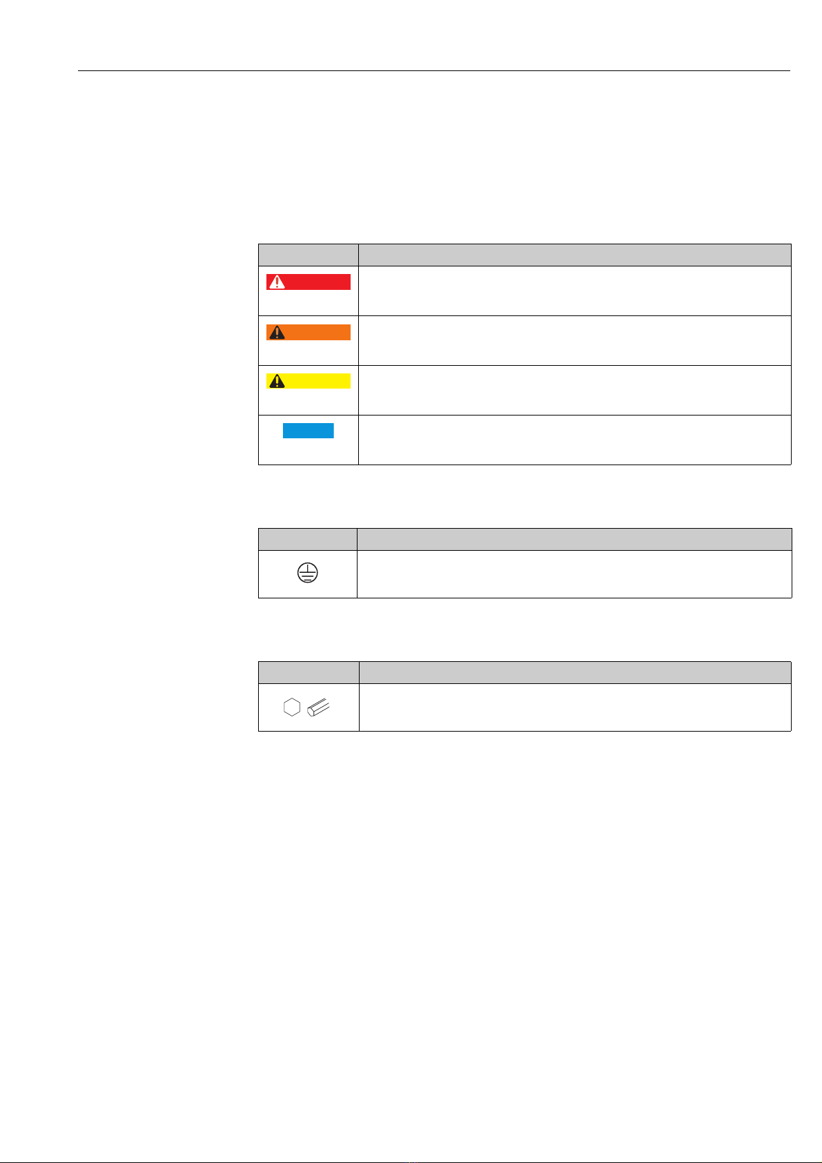
Symbol Meaning
DANGER!
A0011189-EN
A0011190-EN
A0011191-EN
A0011192-EN
This symbol alerts you to a dangerous situation. Failure to avoid this situation will result in
serious or fatal injury.
WARNING!
This symbol alerts you to a dangerous situation. Failure to avoid this situation can result in
serious or fatal injury.
CAUTION!
This symbol alerts you to a dangerous situation. Failure to avoid this situation can result in
minor or medium injury.
NOTICE!
This symbol contains information on procedures and other facts which do not result in
personal injury.
1.4.2 Electrical symbols
Symbol Meaning
Protective ground connection
A terminal which must be connected to ground prior to establishing any other connections.
A0018339
1.4.3 Tool symbols
Symbol Meaning
Allen key
A0011221
Endress+Hauser 5
Safety instructions Micropilot S FMR540 4 to 20 mA HART
1.4.4 Symbols for certain types of information
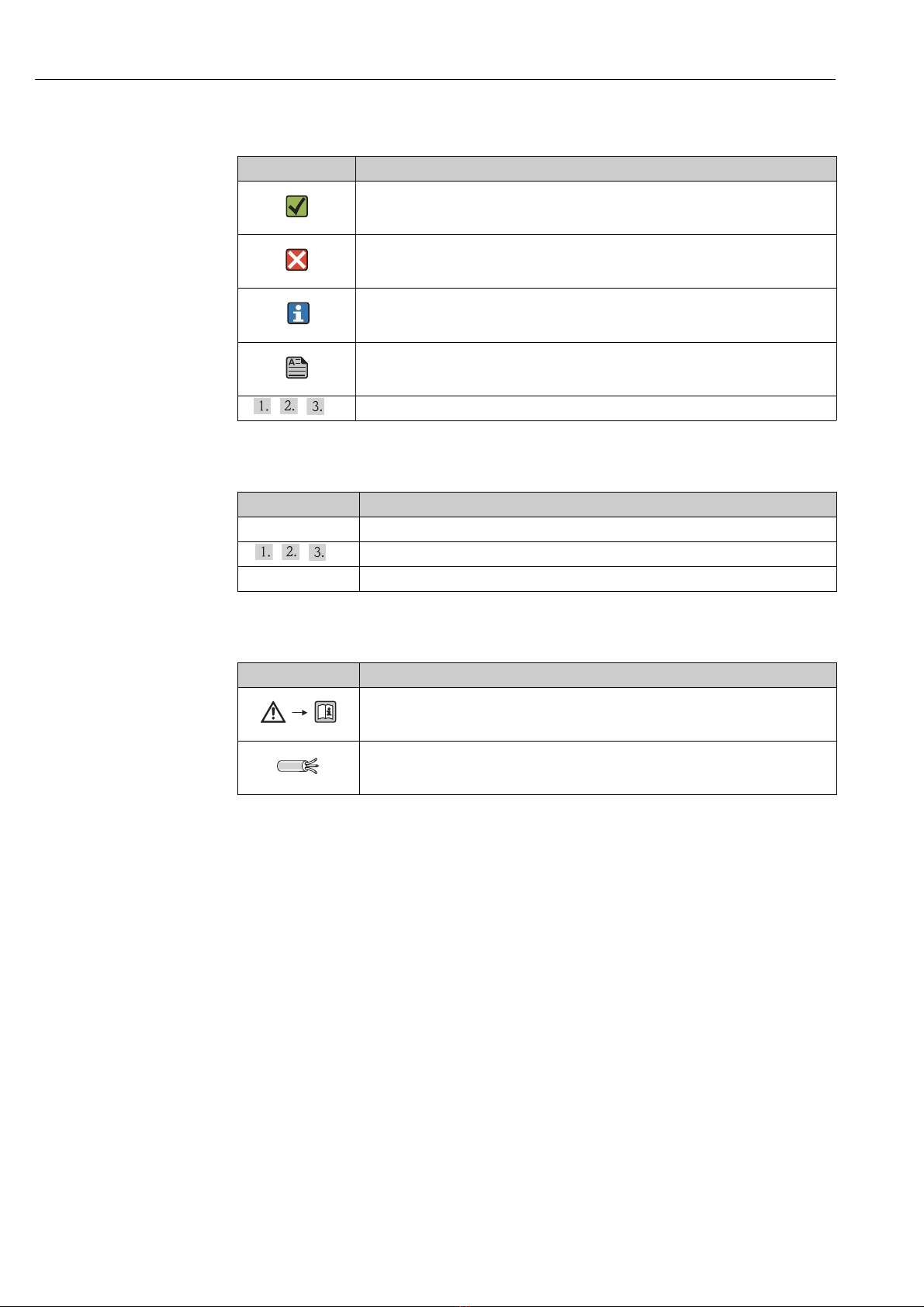
Symbol Meaning
Allowed
Indicates procedures, processes or actions that are allowed.
A0011182
Forbidden
Indicates procedures, processes or actions that are forbidden.
A0011184
Tip
Indicates additional information.
A0011193
Reference to page
Refers to the corresponding page number.
A0015484
, , ,... Series of steps
1.4.5 Symbols in graphics
Symbol Meaning
1, 2, 3, 4, ... Item numbers
, , ,... Series of steps
A, B, C, D, ... Views
1.4.6 Symbols at the device
Symbol Meaning
Safety instructions
Observe the safety instructions contained in the associated Operating Instructions.
A0019159
Temperature resistance of the connection cables
Specifies the minimum value of the temperature resistance of the connection cables.
A0019221
6 Endress+Hauser
Micropilot S FMR540 4 to 20 mA HART Identification
Order Code:
Ser.-No.:
ENDRESS+HAUSER
Made in Germany
D-79689 Maulburg
if modification
see sep. label
X =
MICROPILOT S
0700
Anschlusswerte u. Temp.-Klasse siehe/
Connection values and temp.-classific.
see
T > 60°C
amb
1
2
3
76
9
10
t >85°C
8
Messbereich
Measuring range
max.
Antenne
T max. °C
5
PN max.
4
Dat./Insp.:
12
11
ENDRESS+HAUSER
MICROPILOT S FMR
Hersteller / Producer :
Zert.Messbereich/Cert.Measuring range
Umgeb./Environm.
bis
to
min
max
von
from
Baujahr
Year of constr.
Zertifikat-Nr.
Certification no.
T
m
°C
D00748-C
Tank-Nr.
Tank-no.
Tankreferenzhöhe
Tank reference height
m
1
2
3
4
5
56
7
2 Identification
2.1 Device designation
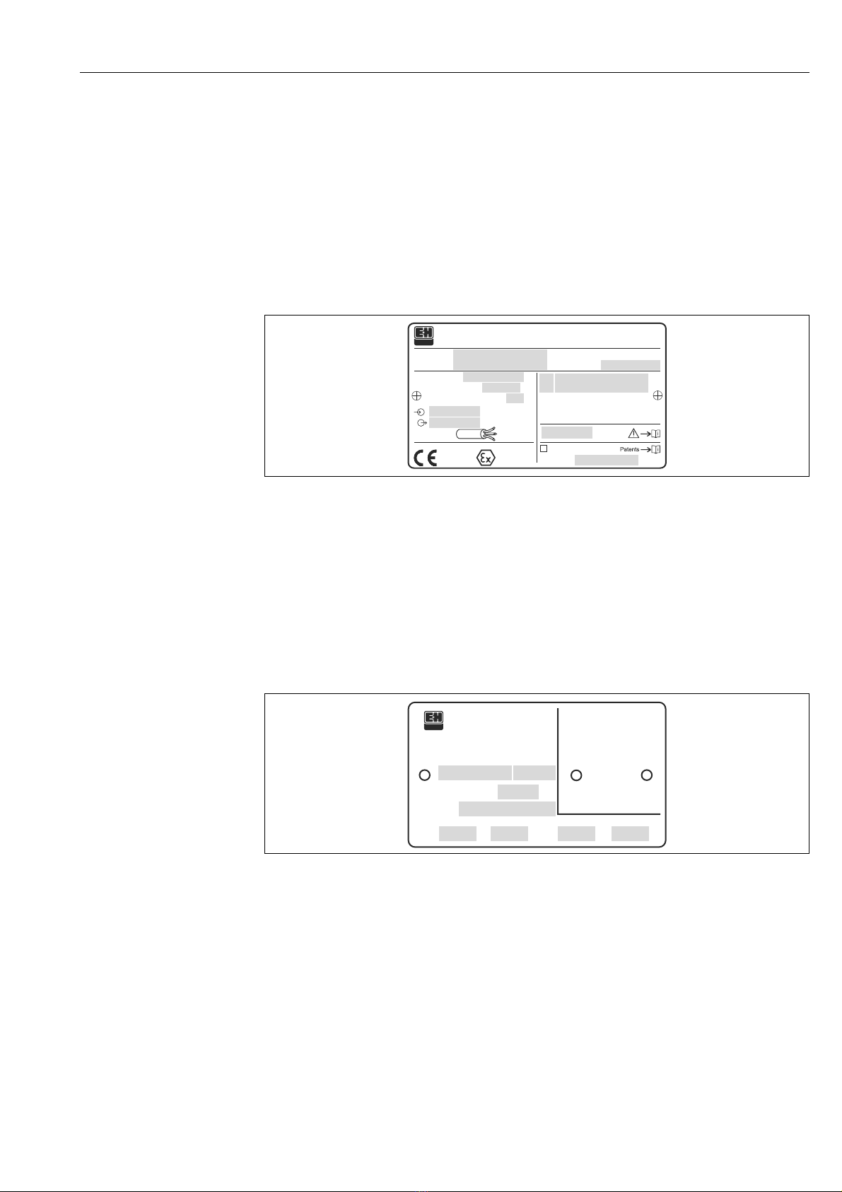
2.1.1 Nameplate
Device nameplate
The following technical data are given on the device nameplate:
1Order code
2 Serial number
3 Degree of protection e.g. IP65, IP67
4 Max. permissible pressure in tank
5 Max. permissible temperature on the antenna
6 Certificate symbol (optional) e.g. Ex
7 Approval number and type of protection
8Max. measuring range
9Power supply
10 Current supply
11 Safety infromation (Connection values and temp.-classific.)
12 Dat.Insp. xx/yy (xx = week of production, yy = year of production)
NMI type plate
Note!
The fields are only filled if in feature "70" "Weight + measures approval" the variant "F" is selected.
1 Certificate number
2Year of construction
3 Tank reference height
4Tank number
5 Certificated measuring range from ... to ...
6 Min. environment temperature
7 Max. environment temperature
A0021526
A0020413
Endress+Hauser 7

Identification Micropilot S FMR540 4 to 20 mA HART
ENDRESS+HAUSER
MICROPILOT S FMR
Hersteller / Producer :
Tank-Nr.
Tank-no.
Baujahr
Year of constr.
Tankreferenzhöhe
Tank reference height
m
D00549-B
Zert.Messbereich/Cert.Measuring range
Umgeb./Environm.
bis
to
min
max
von
from
T
m
°C
1
2
3
4
5
66 7 8
PTB type plate
A0020446
Note!
The fields are only filled if in feature "70" "Weight + measures approval" the variant "G" is selected.
1 Approval number
2 Year and month of type approval
3 Year of construction
4 Tank reference height
5Tank number
6 Certificated measuring range from ... to ...
7 Min. environment temperature
8 Max. environment temperature
8 Endress+Hauser

Micropilot S FMR540 4 to 20 mA HART Identification
CAUTION
!
2.2 Scope of delivery
It is essential to follow the instructions concerning the unpacking, transport and
storage of measuring devices given in the chapter "Incoming acceptance, transport,
storage", ä 10!
The scope of delivery consists of:
• Assembled device
• Accessories ( ä 63)
•2 seals
• Endress+Hauser operating program on the enclosed CD-ROM
• Brief operating instructions KA01059F/00/EN for quick commissioning
• Brief operating instructions KA00255F/00/A2 (basic setup/troubleshooting), housed in
the device
• Approval documentation: if this is not included in the operating manual
• CD-ROM with further documentation, e.g.
– Operating Instructions
– Description of Instrument Functions
2.3 Certificates and approvals
CE mark, declaration of conformity
The device is designed to meet state-of-the-art safety requirements, has been tested and left
the factory in a condition in which it is safe to operate. The device complies with the
applicable standards and regulations as listed in the EC declaration of conformity and thus
complies with the statutory requirements of the EG directives. Endress+Hauser confirms the
successful testing of the device by affixing to it the CE mark.
2.4 Registered trademarks
KALREZ®, VITON®, TEFLON
Registered trademark of the company, E.I. Du Pont de Nemours & Co., Wilmington, USA
TRI-CLAMP
®
Registered trademark of the company, Ladish & Co., Inc., Kenosha, USA
®
HART
Registered trademark of HART Communication Foundation, Austin, USA
®
ToF
Registered trademark of the company Endress+Hauser GmbH+Co. KG, Maulburg, Germany
PulseMaster
®
Registered trademark of the company Endress+Hauser GmbH+Co. KG, Maulburg, Germany
PhaseMaster
®
Registered trademark of the company Endress+Hauser GmbH+Co. KG, Maulburg, Germany
FieldCare
®
Registered trademark of the Endress+Hauser Process Solutions AG, Reinach, Switzerland
®
Endress+Hauser 9
Installation Micropilot S FMR540 4 to 20 mA HART
CAUTION
!
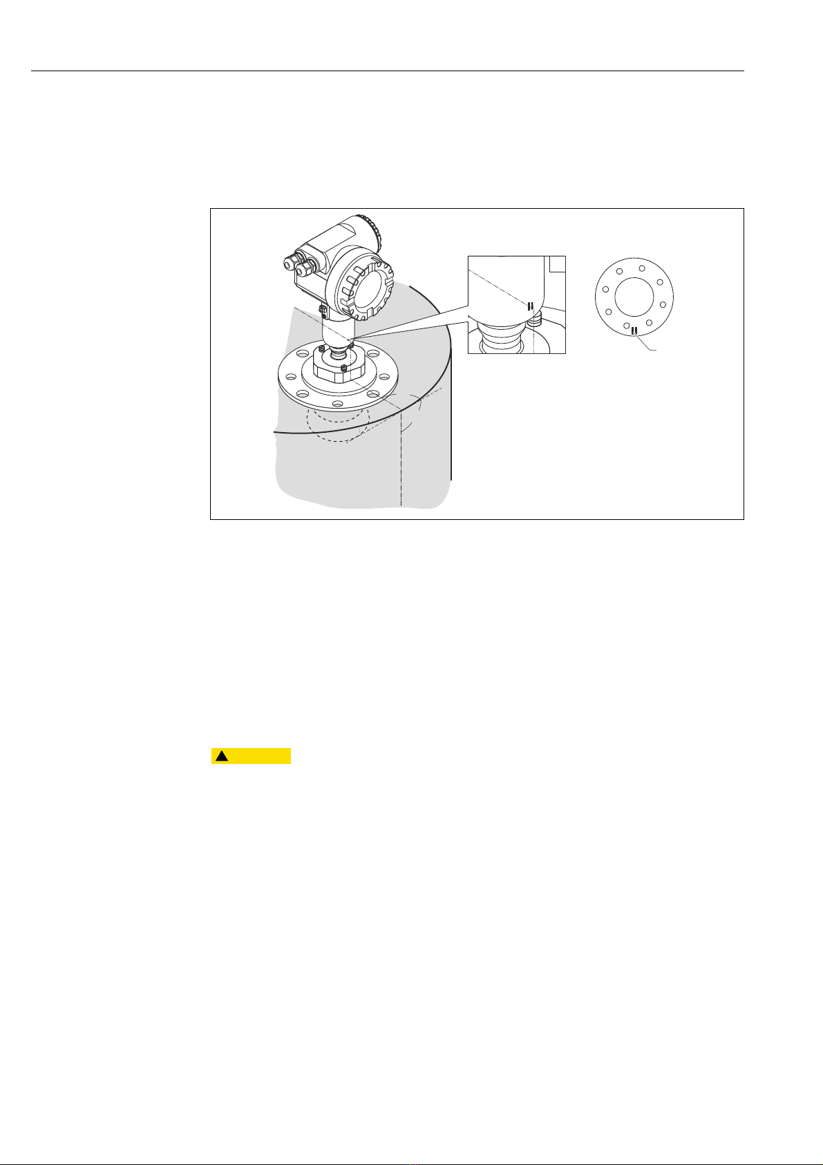
90°
90°
2
1
3Installation
3.1 Quick installation guide
A0020810
1Marker at sensor
2 Marker at flange
3.2 Incoming acceptance, transport, storage
3.2.1 Incoming acceptance
Check the packing and contents for any signs of damage. Check the shipment, make sure
nothing is missing and that the scope of supply matches your order.
3.2.2 Transport
Follow the safety instructions and transport conditions for devices of more than
18 kg (39.69 lbs).
3.2.3 Storage
Pack the measuring device so that is protected against impacts for storage and transport.
The original packing material provides the optimum protection for this.
The permissible storage temperature is -40 to +80 °C (-40 to +176 °F).
10 Endress+Hauser

Micropilot S FMR540 4 to 20 mA HART Installation
1
234
1
3
2
BD
SD
3.3 Installation conditions
3.3.1 Engineering hints
Orientation
• Recommended distance (1) wall - outer
edge of nozzle: ~1/6 of tank diameter
("Beam angle", ä 12).
• Not in the centre (3), interference can
cause signal loss.
• Not above the fill stream (4).
• It is recommended to use a weather
protection cover (2) in order to protect the
transmitter from direct sun or rain.
Assembly and disassembly is simply done
by means of a tension clamp ("Accessories",
ä 63).
A0020541
Tank installations
• Avoid any installations (1), like limit
switches, temperature sensors, etc., inside
the signal beam ("Beam angle", ä 12).
• It is essential that HiHi alarm is below the
blocking distance (BD) and the safety
distance (SD).
• Symmetrical installations (2), e.g. vacuum
rings, heating coils, baffles, etc., can also
interfere with the measurement.
Optimization options
• Antenna size: the bigger the antenna, the
smaller the beam angle, the less
interference echoes.
• Mapping: the measurement can be
optimized by means of electronic
suppression of interference echoes.
• Antenna alignment:
"Optimum mounting position", ä 15.
• Stilling well: a stilling well can always be
used to avoid interference. The FMR532
A0020450
with planar antenna is recommended for
stilling wells with a diameter DN150 (6")
and larger.
• Metallic screens (3) mounted at a slope
spread the radar signals and can,
therefore, reduce interference echoes.
Please contact Endress+Hauser for further
information.
Endress+Hauser 11
Installation Micropilot S FMR540 4 to 20 mA HART
D
W
a
D
W
a
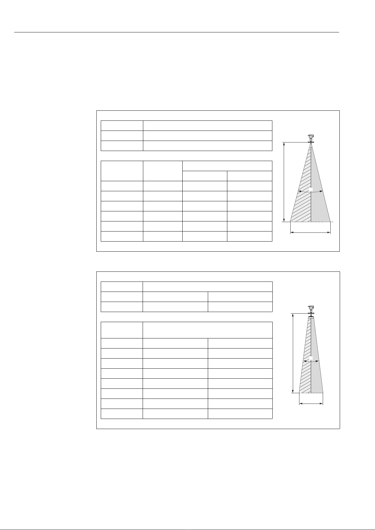
Beam angle
The beam angle is defined as the angle where the energy density of the radar waves
reaches half the value of the maximum energy density (3dB-width). Microwaves are also
emitted outside the signal beam and can be reflected off interfering installations. Beam
diameter W is a function of antenna type (beam angle ) and measuring distance D. The
recommended distance to the tank wall is indicated in the tables below. It is strongly
recommended to avoid any mechanical obstacles within the highlighted area.
Horn antenna
Antenna size 100 mm (4")
Beam angle () 8°
Measuring
distance (D)
5 m (16 ft) 0,70 m (2.3 ft) 0,89 m (2.9 ft) 0,62 m (2 ft)
10 m (33 ft) 1,40 m (2.6 ft) 1,77 m (5.8 ft) 1,23 m (4 ft)
15 m (49 ft) 2,10 m (6.9 ft) 2,65 m (8.7 ft) 1,85 m (6.1 ft)
20 m (66 ft) 2,80 m (9.2 ft) 3,53 m (12 ft) 2,46 m (8.1 ft)
25 m (82 ft) 3,50 m (11 ft) 4,41 m (14 ft) 3,07 m (10 ft)
30 m (98 ft) 4,20 m (14 ft) 5,29 m (17 ft) 3,69 m (12 ft)
Antenna size 200 mm (8") 250 mm (10")
Beam angle () 4.4° 3.3°
Measuring
distance (D)
5m (16ft) 0,35 m (1.1ft) 0,2 m (0.7ft)
10 m (33 ft) 0,70 m (2.3 ft) 0,5 m (1.6 ft)
15 m (49 ft) 1,05 m (3.4 ft) 0,75 m (2.5 ft)
20 m (66 ft) 1,40 m (2.6 ft) 1,05 m (3.4 ft)
25 m (82 ft) 1,75 m (5.7 ft) 1,3 m (4.3 ft)
30 m (98 ft) 2,10 m (6.9 ft) 1,6 m (5.2 ft)
35 m (115 ft) 2,45 m (8 ft) 1,85 m (6.1 ft)
40 m (131 ft) 2,80 m (9.2 ft) 2,10 m (6.9 ft)
Beamwidth
diameter (W)
Recommended distance to wall
Recommended distance to wall
0° tilting 3° tilting
Parabolic antenna
A0020805
A0020806
12 Endress+Hauser

Micropilot S FMR540 4 to 20 mA HART Installation
100%
0%
B
A
C
Measuring conditions
• Tank diameter and height should be at least dimensioned such that a reflection of the
radar signal on both sides of the tank can be avoided.
• In case of media with a low dielectric constant (media groups A and B), the tank bottom
can be visible through the medium at low levels (low height C). Reduced accuracy has to
be expected in this range. If this is not acceptable, we recommend positioning the zero
point at a distance C (see Fig.) above the tank bottom in these applications.
• In principle it is possible to measure up to the tip of the antenna with FMR540. However,
due to considerations regarding accuracy corrosion and build-up, the end of the measuring
range should not be chosen any closer than A (see A in Fig.).
1)
4" Horn antenna 8" Parabolic antenna 10" Parabolic antenna All antennas
FMR540 (without extension) 870 (34.3) 502 (19.8) 530 (20.9) >0.5 (1.6) >300 (11.8)
FMR540 with Extension 150 mm (5.9 in) 1020 (40.2) 652 (25.7) 680 (26.8) >0.5 (1.6) >300 (11.8)
FMR540 with Extension 250 mm (9.8 in) 1120 (44.1) 752 (29.6) 780 (30.7) >0.5 (1.6) >300 (11.8)
FMR540 with Extension 450 mm (18 in) 1320 (52.0) 952 (37.5) 980 (38.6) >0.5 (1.6) >300 (11.8)
1) All values are based on reference conditions.
A [mm (in)] B [m (ft)] C [mm (in)]
Behaviour if measuring range is exceeded
The behaviour in case of the measuring range being exceeded can be freely set:
The default setting is a current of 22 mA and the generation of a digital warning (E651).
A0020737
Endress+Hauser 13

Installation Micropilot S FMR540 4 to 20 mA HART
Measuring range
The usable measuring range depends on the size of the antenna, the reflectivity of the
medium, the mounting location and eventual interference reflections. To achieve an
optimised signal strength it is recommended to use an antenna with as large as possible
diameter (DN200(8") or DN250 (10") parabolic antenna).
The following tables describe the groups of media as well as the achievable measuring range
as a function of application and media group. If the dielectric constant of a medium is
unknown, it is recommended to assume media group B to ensure a reliable measurement.
Media group DC (r) Examples
A1 1.4 to 1.6 Propane, butane
A2 1.6 to 1.9 Non-conducting liquids, kerosene, jet fuels, gasoline, LPG
B 1.9 to 4
C 4 to 10 E.g. concentrated acids, organic solvents, esters, aniline, alcohol, acetone, …
D > 10 Conducting liquids, e.g. aqueous solutions, dilute acids and alkalis
Non-conducting liquids, e.g. gasline, diesel fuel, heavy oil, motor oil, asphalt,
bitumen, BTEX, residual fuel
Measuring range depending on sensor type and media group
Media group Horn antenna
A1 DC (r) = 1.4 to 1.6 Please contact your Endress+Hauser sales organization.
A2 DC (
Max. measuring range with
cudstody transfer approval
r) = 1.6 to 1.9 0,6...20 m (2...66 ft) 0,6...40 m (2...131 ft)
B DC (
r) = 1.9 to 4 0,6...20 m (2...66 ft) 0,6...40 m (2...131 ft)
C DC (
r) = 4 to 10 0,6...30 m (2...98 ft) 0,6...40 m (2...131 ft)
D DC (r) > 10 0,6...30 m (2...98 ft) 0,6...40 m (2...131 ft)
without sensor extension
Measuring range
NMi: 23 m (75 ft)
PTB: 23 m (75 ft)
1)
Parabolic antenna
without sensor extension
Measuring range
NMi: 26 m (85 ft)
PTB: 30 m (98 ft)
1)
1) All values are based on reference conditions.
For stilling well applications Micropilot S FMR532 is recommended
(see TI01122F/00/EN).
14 Endress+Hauser

Micropilot S FMR540 4 to 20 mA HART Installation
90°
90°
2
1
3.4 Installation instructions
3.4.1 Mounting kit
For the mounting , you will require the following tool:
• The tool for flange mounting
• 90 mm wrench for adjustment of the alignment device
(only for devices with alignment device)
• 4 mm (0.1") Allen wrench for turning the housing
3.4.2 Installation in vessel
Optimum mounting position
A0020810
1Marker at sensor
2 Marker at flange
Endress+Hauser 15

Installation Micropilot S FMR540 4 to 20 mA HART
H
øD
Standard installation FMR540 with horn
antenna
• Observe installation instructions, ä 11.
• Marker must be aligned towards tank wall.
The marker is located clearly visible on the
sensor neck or the flange.
• After mounting, the housing can be turned
350° in order to simplify access to the
display and the terminal compartment.
• Adjust vertical sensor alignment in case
the flange is not parallel to the face is
medium surface.
• The horn antenna should protrude from
the nozzle. If necessary, choose version
with antenna extension. Please contact
Endress+Hauser for application with
A0020809
higher nozzle.
• The horn antenna should be installed with
3° inclination towards the tank center.
To avoid interference reflections or for
optimum alignment within the tank, the
FMR540 with optional alignment device
can be swiveled by 15° in all directions. For
more informations please see Operating
Instructions KA00274F/00/A2.
Please contact Endress+Hauser Service
Organization for commissioning.
Antenna size 100 mm (4")
D [mm (in)] 95 (3.74)
H [mm (in)]
(without antenna extension)
< 430 (16.9)
16 Endress+Hauser

Micropilot S FMR540 4 to 20 mA HART Installation
øD
H
AB
1
a
a
Standard installation FMR540 with parabolic antenna
• Observe installation instructions, ä 11.
• Marker is aligned towards tank wall.
The marker is located clearly visible on the sensor neck or the flange.
• After mounting, the housing can be turned 350° in order to simplify access to the display
and the terminal compartment.
• Ideally the parabolic antenna should protrude from the nozzle (1). Particularly when using
the alignment device, please ensure that the parabolic reflector is protruding from the
nozzle/roof so as not to inhibit alignment.
For application with higher nozzle install parabolic antenna completely in the
nozzle (B), including RF-wave guide.
• The parabolic antenna should be installed vertically.
To avoid interference reflections or for optimum alignment within the vessel, the FMR540
with optional alignment device can be swiveled by 15° in all directions.
For more informations please see Operating Instructiosn KA00274F/00/A2.
Please, contact Endress+Hauser Service organization for commissioning.
A Antenna protrudes from the nozzle
B Antenna mounted in nozzle
1 Mounted perpendicular to the liquid surface
aObserve distance
(without antenna extension)
Antenna size 200 mm (8") 250 mm (10")
D [mm (in)] 173 (6.81) 236 (9.29)
H [mm (in)]
< 200 7.87) < 200 (7.87)
A0020808
Endress+Hauser 17

Installation Micropilot S FMR540 4 to 20 mA HART
±15°
±15°
90 °
90 °
A
FMR540 with alignment device
Micropilot S should be installed vertically towards the Liquid surface for best measuring
performance of ±1 mm (0.04 in). Using the alignment device it is possible to tilt the antenna
axis by up to 15° in all directions. The alignment device is used for the optimum alignment
of the radar beam to the liquid surface. The Sensor should be positioned vertical to the liquid
surface in inclination of 0° for Parabolic Antenna and up to 3° for Horn Antenna.
A0020807
AMedium
To align the antenna as precisely as possible, it is recommended to use the sensor alignment
tool, which is available as an accessory.
For more informations please see instructions in KA00274F/00/A2.
In case of custody Application, the screws must be locked with wires.
18 Endress+Hauser

Micropilot S FMR540 4 to 20 mA HART Installation
M
a
d
e
in
G
e
r
m
a
n
y
M
a
u
l
b
u
r
g
Made in Germany Maulburg
IP65
M
e
s
s
b
e
re
ic
h
M
e
a
s
u
rin
g
r
a
n
g
e
Messbereich
Measuring range
U
1
6
...3
6
V
D
C
4
...
2
0
m
A
U 16...36 V DC
4...20 mA
m
a
x
. 2
0
m
max. 20 m
T>
70
°
C
:
A
t >
8
5°C
T >70°C :
A
t >85°C
O
rd
e
r
C
o
d
e
:
S
e
r
.
-
N
o
.
:
Order Code:
Ser.-No.:
SS+HAUSER
OPILOTFM
R
SS+HAUSER
OPILOTFMR
1
3
2
±15°
±15°
90 °
90 °
A
Sensor alignment tool for alignment device
A sensor alignment tool (1) is recommended to be
used at the time of installation for FMR540 with
alignment device.
Alignment procedure
This procedure is only applicable to the sensors
purchased with alignment device (3). To carry
out this procedure requires an accessory from
Endress+Hauser, sensor alignment tool (1) for
Micropilot S FMR540.
Before starting this procedure, please observe
Micropilot S FMR540 has been mounted on the
tank in proper position and all flange bolts (2) are
tightened.
Tools: 90 mm open wrench
Accessory Package contains:
Sensor alignment tool (part no. 52026756)
A0021554
Description of procedure "Sensor Alignment using
Sensor alignment tool"
(KA00274F/00/A2 part no. 52027425)
Loosen the nut (3), so that the FMR540 can tilt
smoothly.
Observe the sensor can smoothly tilt its
position. The nut should not be too loose.
Tilt the Micropilot S to approximately vertical
to the medium surface (A) or horizontal plane.
A0020807
Endress+Hauser 19

Installation Micropilot S FMR540 4 to 20 mA HART
90°
90°
M
a
d
e
in
G
e
rm
a
n
y
M
a
u
lb
u
rg
Made in Germany Maulburg
IP65
M
e
s
s
b
er
e
ic
h
M
e
a
s
u
rin
g
ra
n
g
e
Messbereich
Measuring range
U
16
...3
6
V
D
C
4
...2
0
m
A
U 16...36 V DC
4...20 mA
m
a
x
. 2
0
m
max. 20 m
T>
7
0
°
C
:
A
t
>
8
5
°
C
T >70°C :
A
t >85°C
O
rd
er
C
o
d
e
:
S
e
r
.-
N
o
.:
Order Code:
Ser.-No.:
SS+
HAUSE
R
O
PILO
T
FM
R
SS+HAUSER
OPILOTFMR
1
4
5
3°
2°
1°
0°
Endress+Hauser
52026756
Place the Sensor alignment tool (1) for
Micropilot S FMR540. Please, note to avoid any
obstacles between the backside of the
Alignment tool and the nameplate of
Micropilot S FMR540.
A0021550
Micropilot S FMR540 with Horn Antenna:
Tilt the FMR540 targeting the direction of tank
center up to the position where the angle
indicators`s outer circle reaches the circle of 3
deg (4).
Exceeding the 3 degree position may
cause a weaker signal (or loss of signal).
Micropilot S FMR540 with Parabolic
Antenna:
Tilt the FMR540 to the position where the
bubble comes into the center (5) of the
inclination indicator (0 deg).
Gradually tighten the nut of the alignment tool
and make sure to keep the position of 0
degree/3 degree inclination.
After tightening the nut, check if the sensor
A0021415
cannot tilt and change its position. Torque for
the nut: 80 to 85 Nm (59 to 62.69 lbf ft).
If it is required by the local custody transfer
authority, please seal the alignment device at
the sealing screws using the provided wires
and seal metals.
20 Endress+Hauser
Micropilot S FMR540 4 to 20 mA HART Installation
NOTICE
M
a
d
e
i
n
G
e
r
m
a
n
y
M
a
u
l
b
u
r
g
IP 65
M
essb
ereich
M
eas
urin
g
range
U
16...36 V DC
4...20 mA
m
ax.
20 m
T >70
°C :
A
t
>
8
5
°
C
O
rder Code:
Ser.-No
.:
Order Code:
Ser.-No.:
SS
+HAUSER
OPILOT FM
R
1
4 mm
Sealing for custody transfer applications
The alignment device can be sealed using
the provided slotted capstan screws. The seal
wires must be installed against the open
direction in order to assure that a loosening
of the alignment device is not possible.
It is recommended to seal at least two of the
three sealing points provided.
A0021559
Integrated air purge connection
In some applications, the integrated air
purge connection can prevent clogging of
the antenna.
• Permanent operation:
recommended pressure range of the purge
air: 1.2 to 1.5 bar (18 to 22.5 psi) abs.
•Pulsed operation:
max. pressure of purge air: 6 bar abs.
Moisture or dust can collect and lead to
false measurement results!
‣ Make sure to use dry purge air!
1 Air purge connection G1/4"
(max. torque 3,5 Nm (2.58 lbft ft)
A0020799
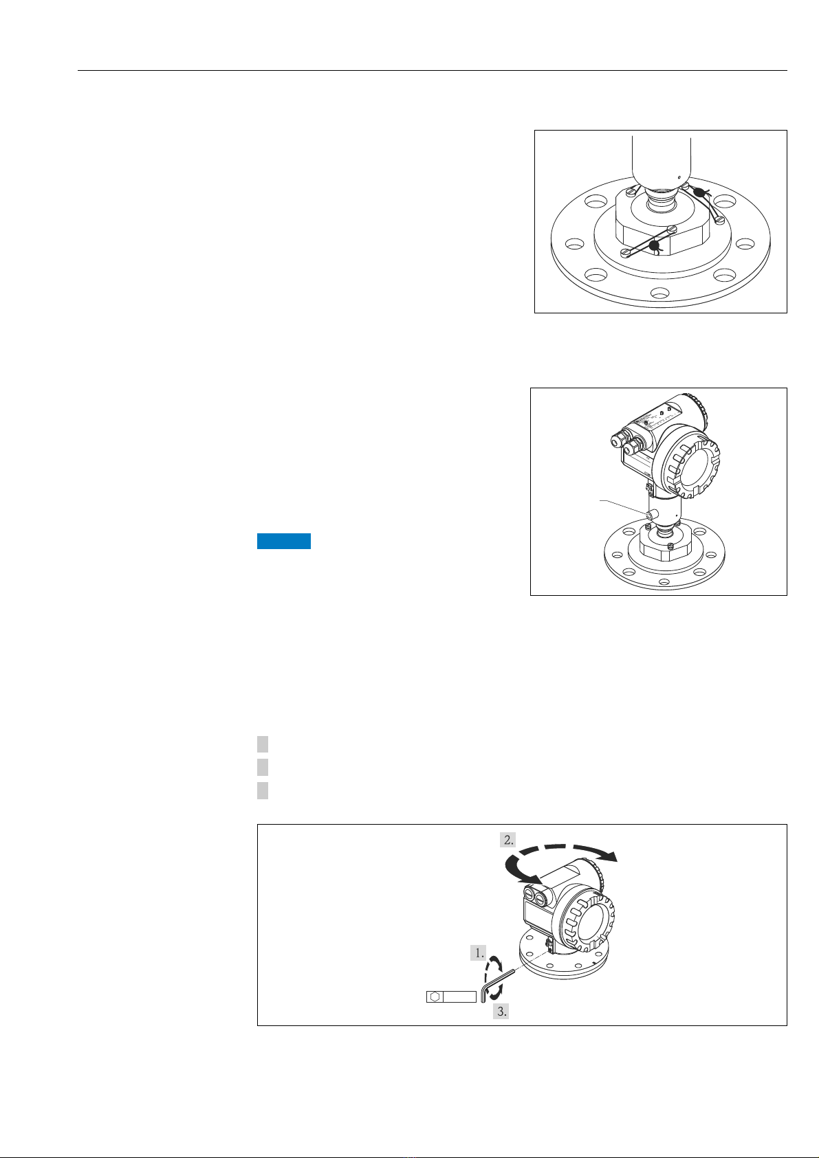
3.4.3 Turn housing
After mounting, the housing can be turned 350° in order to simplify access to the display and
the terminal compartment. Proceed as follows to turn the housing to the required position:
1. Undo the allen screw
2. Turn the housing in the required direction
3. Tighten up the allen screw strongly by hand
A0020470
Endress+Hauser 21

Installation Micropilot S FMR540 4 to 20 mA HART
90°
280 (11.0)
ø23 (0.91)
240 (9.45)
A-A
8 (0.31)
ø80.3 (3.16)
A
A
A
A
ø340 (13.4)
ø405 (15.9)
90°
60°
60°
ø26 (1.02)
ø29 (1.14)
ø358 (14.1)
ø294.5 (11.6)
A
A
BC
D
3.4.4 Endress+Hauser UNI flange
The number of bolts has sometimes been reduced. The bolt-holes have been enlarged for
adaption of dimensions, therefore, the flange needs to be properly aligned to the
counterflange before the bolts are tightened.
Dimensions: mm (in)
Endress+Hauser
UNI Flange
B DN150 PN16; ANSI 6" 150 lbs; JIS 10K 150 040 XVJ
C DN200 PN16; ANSI 8" 150 lbs; JIS 10K 200 040 X3J
D DN250 PN16; ANSI 10" 150lbs; JIS 10K 250 040 X5J
Compatibel with: Feature Option
A0020793
model
22 Endress+Hauser

Micropilot S FMR540 4 to 20 mA HART Installation
8 (0.31)
±15°
56.8 (2.24)
A
A-A
A
90
2
1
3.4.5 Alignment unit with Endress+Hauser UNI flange
A0020791
Dimensions: mm (in)
1Viton-Dichtung
2 Endress+Hauser UNI Flange DN200/DN250
Please, also see sensor alignment tool ä 63.
3.5 Post-installation check
After the measuring device has been installed, perform the following checks:
• Is the measuring device damaged (visual check)?
• Does the measuring device correspond to the measuring point specifications such as
process temperature/pressure, ambient temperature, measuring range, etc.?
• Is the flange marking correctly aligned ( ä 10)?
• Have the flange screws been tightened up with the respective tightening torque?
• Are the measuring point number and labeling correct (visual check)?
• Is the measuring device adequately protected against rain and direct sunlight ( ä 63)?
Endress+Hauser 23

Wiring Micropilot S FMR540 4 to 20 mA HART
CAUTION
!
CAUTION
!
CAUTION
!
1
3
2
6
112233445
5
8
A
B
5
7
4
4 Wiring
4.1 Quick wiring guide
When grounding conductive screens, the corresponding directives EN 60079-14 and
EN 1127-1 must be observed. Recommendation for safe grounding of conductive screens:
Before connection please note the following:
‣ The power supply must be identical to the data on the nameplate.
‣ Switch off power supply before connecting the device.
‣ Connect equipotential bonding to transmitter ground terminal before connecting the
device.
‣ Tighten the locking screw:
It forms the connection between the antenna and the housing ground potential.
‣ When you use the measuring system in hazardous areas, make sure you comply with
national standards and the specifications in the safety instructions (XA’s)
4.1.1 Wiring
Before connection please note the following:
‣ The power supply to be delivered by a transmitter supply unit.
‣ Befor removing housing cover at seperate connection compartment turn off the power
supply!
Insert cable through gland . Use screened,
twisted 2-wire or 4-wire cable.
Only ground screening of the line on
sensor side.
Make connection (see pin assignment).
Tighten cable gland.
Replace and tighten off housing cover.
Switch on power supply.
A Micropilot S situated in a hazardous
area is connected as a single device to a
power supply unit and transmitter
situated outside of the hazardous area.
In this case, it is recommended that the
screen be connected directly to the
Micropilot at the housing’s earth,
whereby the Micropilot S and the power
supply unit are connected to the same
potential equalization line.
24 Endress+Hauser
A Power 24 VDC; from a transmitter supply unit
B Signal 24 VDC; from a transmitter supply unit
1Housing cover
2Cable
3 Cable gland
4 Alternative connection
5 Commubox FXA195, Field Communicator
6Shield ground
7 Test socket; Output current
8 PML (potential matching line)
A0020479
 Loading...