

Endress+Hauser FMR540 Specifications
TI00412F/00/EN/17.16
71349622
Products Solutions Services
Technical Information
Micropilot S FMR540
Level-Radar
Level transmitter for continuous and non-contact
precision level measurement
For custody transfer and inventory control
applications with NMi- and PTB-approvals.
Application
The Micropilot S is used for highly accurate level measurement in storage tanks and
can be applied in custody transfer applications. It meets the relevant requirements
according to OIML R85 and API 3.1B.
Typical areas of application are:
• The Micropilot S with parabolic antenna is excellently suited for free space
applications up to 40 m (131 ft).
• The Micropilot S with horn antenna is suitable for free space applications that
disallow the use of a parabolic antenna due to tank/nozzle geometry.
The FMR540 with a DN200 (8") or DN250 (10") parabolic antenna offers high beam
focussing of 4.4° or 3.3° respectively, and is therefore ideally suited to applications with
nozzles situated close to the tank wall. The FMR540 with DN100 (4") horn antenna is
designed for all small nozzles sizes.
Your benefits
• Accuracy: better than 1 mm (0.04 in).
• National approvals (NMi, PTB) for custody transfer.
• Easy integration into tank gauging systems via the Tank Side Monitor NRF590.
• Low-cost, easy installation via 4-wire cable with HART and 24 V DC (intrinsically
safe).
• Low cost, low weight universal flanges.
• Alignment device to compensate any flange inclination.
• Easy on-site operation via menu-driven alphanumeric display.
• Easy commissioning, documentation and maintenance/diagnostics via operating
software (FieldCare).
• HART communication.

Table of Content
Micropilot S FMR540
Document information . . . . . . . . . . . . . . . . . . . . . . . . . . .3
Document conventions . . . . . . . . . . . . . . . . . . . . . . . . . . . . . . . . . 3
Function and system design . . . . . . . . . . . . . . . . . . . . . .5
Measuring principle . . . . . . . . . . . . . . . . . . . . . . . . . . . . . . . . . . . 5
Equipment architecture . . . . . . . . . . . . . . . . . . . . . . . . . . . . . . . . 6
Custody transfer applications . . . . . . . . . . . . . . . . . . . . . . . . . . . . 7
Integrated in tank gauging system . . . . . . . . . . . . . . . . . . . . . . . 7
Input . . . . . . . . . . . . . . . . . . . . . . . . . . . . . . . . . . . . . . . . . .8
Measured variable . . . . . . . . . . . . . . . . . . . . . . . . . . . . . . . . . . . . . 8
Measuring range . . . . . . . . . . . . . . . . . . . . . . . . . . . . . . . . . . . . . . 8
Operating frequency . . . . . . . . . . . . . . . . . . . . . . . . . . . . . . . . . . . 9
Output . . . . . . . . . . . . . . . . . . . . . . . . . . . . . . . . . . . . . . . . .9
Output signal . . . . . . . . . . . . . . . . . . . . . . . . . . . . . . . . . . . . . . . . . 9
Signal on alarm . . . . . . . . . . . . . . . . . . . . . . . . . . . . . . . . . . . . . . . 9
Load HART . . . . . . . . . . . . . . . . . . . . . . . . . . . . . . . . . . . . . . . . . . . 9
Linearization . . . . . . . . . . . . . . . . . . . . . . . . . . . . . . . . . . . . . . . . . 9
Galvanic isolation . . . . . . . . . . . . . . . . . . . . . . . . . . . . . . . . . . . . . 9
Protocol specific data . . . . . . . . . . . . . . . . . . . . . . . . . . . . . . . . . . 9
Power supply . . . . . . . . . . . . . . . . . . . . . . . . . . . . . . . . . 10
Terminal assignment . . . . . . . . . . . . . . . . . . . . . . . . . . . . . . . . . 10
Supply voltage . . . . . . . . . . . . . . . . . . . . . . . . . . . . . . . . . . . . . . . 11
Power consumption . . . . . . . . . . . . . . . . . . . . . . . . . . . . . . . . . . . 11
Current consumption . . . . . . . . . . . . . . . . . . . . . . . . . . . . . . . . . 11
Electrical connection . . . . . . . . . . . . . . . . . . . . . . . . . . . . . . . . . . 12
Cable entry . . . . . . . . . . . . . . . . . . . . . . . . . . . . . . . . . . . . . . . . . . 12
Residual ripple HART . . . . . . . . . . . . . . . . . . . . . . . . . . . . . . . . . 12
Max noise HART . . . . . . . . . . . . . . . . . . . . . . . . . . . . . . . . . . . . . 12
Overvoltage protection . . . . . . . . . . . . . . . . . . . . . . . . . . . . . . . . 12
Power supply . . . . . . . . . . . . . . . . . . . . . . . . . . . . . . . . . . . . . . . . 12
Highly accurate measurement . . . . . . . . . . . . . . . . . . . . . . . . . . 12
Performance characteristics . . . . . . . . . . . . . . . . . . . . 13
Reference operating conditions . . . . . . . . . . . . . . . . . . . . . . . . . 13
Maximum measured error . . . . . . . . . . . . . . . . . . . . . . . . . . . . . 13
Resolution . . . . . . . . . . . . . . . . . . . . . . . . . . . . . . . . . . . . . . . . . . . 13
Settling time . . . . . . . . . . . . . . . . . . . . . . . . . . . . . . . . . . . . . . . . . 13
Hysteresis . . . . . . . . . . . . . . . . . . . . . . . . . . . . . . . . . . . . . . . . . . . 13
Non-repeatability . . . . . . . . . . . . . . . . . . . . . . . . . . . . . . . . . . . . 13
Reaction time . . . . . . . . . . . . . . . . . . . . . . . . . . . . . . . . . . . . . . . . 13
Long-term drift . . . . . . . . . . . . . . . . . . . . . . . . . . . . . . . . . . . . . . 13
Influence of ambient temperature . . . . . . . . . . . . . . . . . . . . . . . 13
Proof of accuracy of custody transfer versions . . . . . . . . . . . . . 13
Maximum fill speed . . . . . . . . . . . . . . . . . . . . . . . . . . . . . . . . . . . 13
Software reliability . . . . . . . . . . . . . . . . . . . . . . . . . . . . . . . . . . . 13
Inventory control versions . . . . . . . . . . . . . . . . . . . . . . . . . . . . . 14
Installation . . . . . . . . . . . . . . . . . . . . . . . . . . . . . . . . . . . 15
Installation conditions . . . . . . . . . . . . . . . . . . . . . . . . . . . . . . . . 15
Installation instructions . . . . . . . . . . . . . . . . . . . . . . . . . . . . . . . 15
Measuring conditions . . . . . . . . . . . . . . . . . . . . . . . . . . . . . . . . . 16
Installation on tank . . . . . . . . . . . . . . . . . . . . . . . . . . . . . . . . . . 17
Alignment device . . . . . . . . . . . . . . . . . . . . . . . . . . . . . . . . . . . . . 19
Beam angle . . . . . . . . . . . . . . . . . . . . . . . . . . . . . . . . . . . . . . . . . . 20
Integrated air purge connection . . . . . . . . . . . . . . . . . . . . . . . . 21
Environment . . . . . . . . . . . . . . . . . . . . . . . . . . . . . . . . . 22
Ambient temperature range . . . . . . . . . . . . . . . . . . . . . . . . . . . 22
Storage temperature . . . . . . . . . . . . . . . . . . . . . . . . . . . . . . . . . . 22
Climate class . . . . . . . . . . . . . . . . . . . . . . . . . . . . . . . . . . . . . . . . . 22
Degree of protection . . . . . . . . . . . . . . . . . . . . . . . . . . . . . . . . . . 22
Vibration resistance . . . . . . . . . . . . . . . . . . . . . . . . . . . . . . . . . . 22
Cleaning of the antenna . . . . . . . . . . . . . . . . . . . . . . . . . . . . . . . 22
Electromagnetic compatibility (EMC) . . . . . . . . . . . . . . . . . . . . 22
Approvals for custody transfer applications . . . . . . . . . . . . . . 22
Process . . . . . . . . . . . . . . . . . . . . . . . . . . . . . . . . . . . . . . 22
Process temperature range . . . . . . . . . . . . . . . . . . . . . . . . . . . . 22
Process pressure limits . . . . . . . . . . . . . . . . . . . . . . . . . . . . . . . . 22
Alignment device . . . . . . . . . . . . . . . . . . . . . . . . . . . . . . . . . . . . . 22
Mechanical construction . . . . . . . . . . . . . . . . . . . . . . . 23
Design, dimensions . . . . . . . . . . . . . . . . . . . . . . . . . . . . . . . . . . . 23
Weight . . . . . . . . . . . . . . . . . . . . . . . . . . . . . . . . . . . . . . . . . . . . . 24
Materials . . . . . . . . . . . . . . . . . . . . . . . . . . . . . . . . . . . . . . . . . . . 25
Type plate for custody transfer applications . . . . . . . . . . . . . . 27
Endress+Hauser UNI flange . . . . . . . . . . . . . . . . . . . . . . . . . . . . 29
Operability . . . . . . . . . . . . . . . . . . . . . . . . . . . . . . . . . . . 31
Operation concept . . . . . . . . . . . . . . . . . . . . . . . . . . . . . . . . . . . . 31
Local operation . . . . . . . . . . . . . . . . . . . . . . . . . . . . . . . . . . . . . . 31
Remote configuration . . . . . . . . . . . . . . . . . . . . . . . . . . . . . . . . . 32
Display elements . . . . . . . . . . . . . . . . . . . . . . . . . . . . . . . . . . . . . 34
Operating elements . . . . . . . . . . . . . . . . . . . . . . . . . . . . . . . . . . . 35
Certificates and approvals . . . . . . . . . . . . . . . . . . . . . . 36
CE approval . . . . . . . . . . . . . . . . . . . . . . . . . . . . . . . . . . . . . . . . . 36
C-Tick symbol . . . . . . . . . . . . . . . . . . . . . . . . . . . . . . . . . . . . . . . . 36
Ex approval . . . . . . . . . . . . . . . . . . . . . . . . . . . . . . . . . . . . . . . . . . 36
Overfill prevention . . . . . . . . . . . . . . . . . . . . . . . . . . . . . . . . . . . . 36
RF approvals . . . . . . . . . . . . . . . . . . . . . . . . . . . . . . . . . . . . . . . . . 36
CRN approvals . . . . . . . . . . . . . . . . . . . . . . . . . . . . . . . . . . . . . . . 36
Approvals for custody transfer applications . . . . . . . . . . . . . . 36
External standards and guidelines . . . . . . . . . . . . . . . . . . . . . . 36
Ordering information . . . . . . . . . . . . . . . . . . . . . . . . . . 37
Ordering information . . . . . . . . . . . . . . . . . . . . . . . . . . . . . . . . . 37
Scope of delivery . . . . . . . . . . . . . . . . . . . . . . . . . . . . . . . . . . . . . 37
Accessories . . . . . . . . . . . . . . . . . . . . . . . . . . . . . . . . . . . 37
Device-specific accessories . . . . . . . . . . . . . . . . . . . . . . . . . . . . . 37
Communication-specific accessories . . . . . . . . . . . . . . . . . . . . . 38
Service-specific accessories . . . . . . . . . . . . . . . . . . . . . . . . . . . . 38
Documentation . . . . . . . . . . . . . . . . . . . . . . . . . . . . . . . 39
Standard documentation . . . . . . . . . . . . . . . . . . . . . . . . . . . . . . 39
Supplementary device-dependent documentation . . . . . . . . . 39
Safety Instructions . . . . . . . . . . . . . . . . . . . . . . . . . . . . . . . . . . . . 39
2 Endress+Hauser

Micropilot S FMR540
DANGER
WARNING
CAUTION
NOTICE
Document information
Document conventions Safety symbols
Symbols Meaning
A0011189-EN
A0011190-EN
A0011191-EN
A0011192-EN
Electrical symbols
DANGER!
This symbol alerts you to a dangerous situation. Failure to avoid this situation will result in
serious or fatal injury.
WARNING!
This symbol alerts you to a dangerous situation. Failure to avoid this situation can result in
serious or fatal injury.
CAUTION!
This symbol alerts you to a dangerous situation. Failure to avoid this situation can result in
minor or medium injury.
NOTICE!
This symbol contains information on procedures and other facts which do not result in
personal injury.
Symbols Meaning
Direct current
A terminal at which DC voltage is present or through which direct current flows.
A0018335
Alternating current
A terminal at which AC voltage is present or through which alternating current flows.
A0018336
Direct current and alternating current
• A terminal at which AC voltage or DC voltage is present.
A0018337
• A terminal through which alternating current or direct current flows.
Ground connection
A grounded terminal which, from the operator's point of view, is grounded via a grounding
A0018338
system.
Protective ground connection
A terminal that must be connected to ground before establishing other connections.
A0018339
Equipotential connection
A connection that must be made with the plant grounding system. This could, for example,
A0011201
be a potential matching line or a star-shaped grounding system, depending on national or
company codes of practice.
Symbols for certain types of information
Symbols Meaning
Allowed
Indicates procedures, processes or actions that are allowed.
A0011182
Preferred
Indicates procedures, processes or actions that are preferred.
A0011183
Forbidden
Indicates procedures, processes or actions that are forbidden.
A0011184
Tip
Indicates additional information.
A0011193
Reference to documentation
Refers to the relevant device documentation.
A0015483
Endress+Hauser 3

Reference to page
-
.
Refers to the relevant page number.
A0015484
Reference to diagrams
Refers to the relevant graphic number and page number.
A0015486
, , ... Series of steps
Help in the event of a problem
A0015488
Symbols in graphics
Symbols Meaning
1, 2, 3, 4, ... Numbering for main positions
, , ... Series of steps
A, B, C, D, ... Views
A-A, B-B, ... Sections
Hazardous area
Indicates a hazardous area.
A0011187
Safe area (non-hazardous area)
Indicates a non-hazardous area.
A0011188
Micropilot S FMR540
4 Endress+Hauser
Micropilot S FMR540
20 mA
100%
4mA
0%
D
L
F
E
2
1
Function and system design
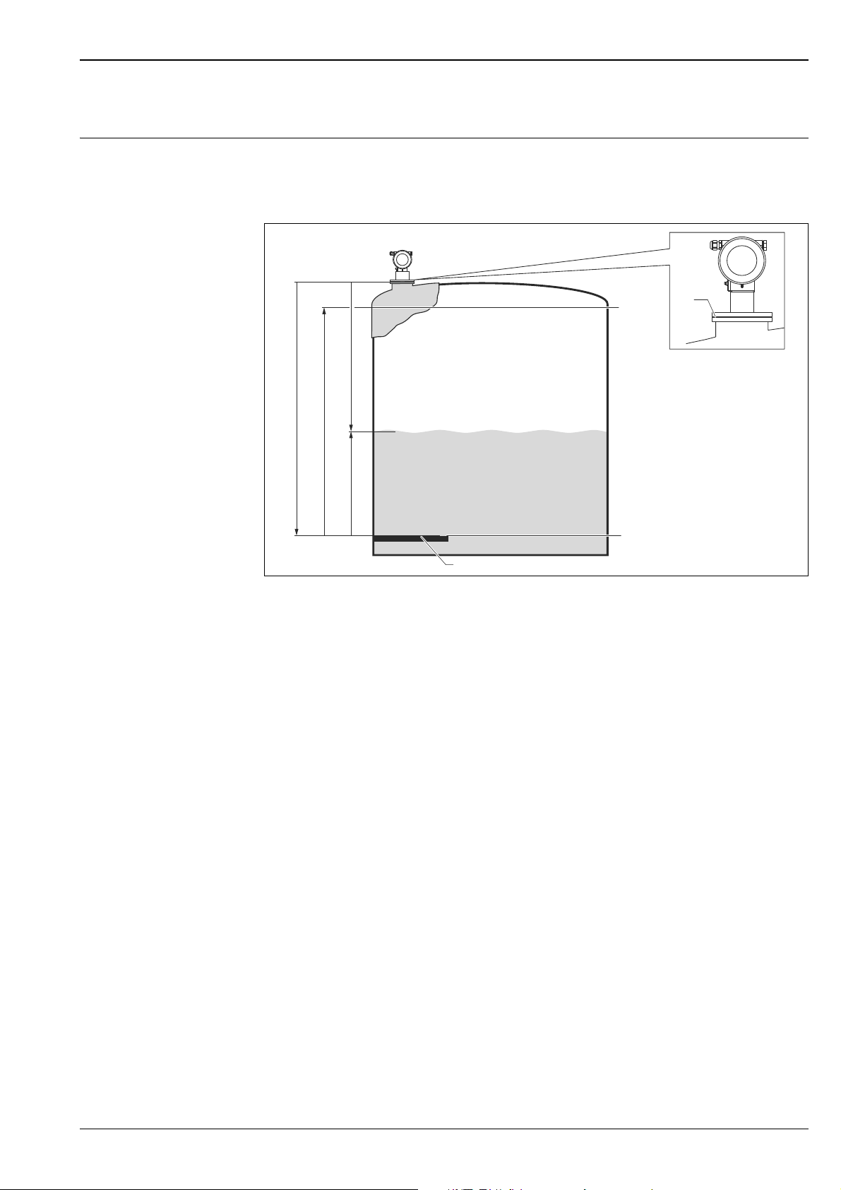
Measuring principle The Micropilot is a "downward-looking" measuring system, operating based on the time-of-flight
method. It measures the distance from the reference point (process connection) to the product surface.
Radar impulses are emitted by an antenna, reflected off the product surface and received again by the
radar system.
A0020712
1 GRH reference point of measurement (bottom edge of flange or threaded connection)
2 Level zero point (gauge reference plate)
E Empty calibration ( = zero point)
F Full calibration (= span)
DDistance measured
L Level (L = E
D)
Input
The reflected radar impulses are received by the antenna and transmitted into the electronics.
A microprocessor evaluates the signal and identifies the level echo caused by the
reflection of the radar impulse at the product surface.
The unambiguous signal identification is accomplished by the PulseMaster® software, based on many
years of experience with time-of-flight technology. The mm-accuracy of the Micropilot S could be
achieved with the patented algorithms of the PulseMaster® software.
The distance "D" to the product surface is proportional to the time of flight "t" of the impulse:
D = c · t/2,
with "c" being the speed of light.
Based on the known empty distance "E", the level "L" is calculated:
L = E – D
Reference point for "E" is the lower surface of the process connection. For highly precise level
measurements, it is of crucial importance to have a stable mounting position (GRH) of the radar gauge
or to compensate for the effects of tank movements during filling and emptying cycles. This can be
done by either using the dip chart integrated in the Micropilot S FMR53x/540 or by using the
compensation methods integrated into the Tank Side Monitor NRF590. The stability of the reference
point for the measurement (GRH) has a decisive influence on the accuracy of the measurement! The
Micropilot is equipped with functions to suppress interference echoes. The user can activate these
functions. They ensure that interference echoes (e.g. from edges and weld seames) are not interpreted
as level echo.
Endress+Hauser 5
Output
ENDRESS + HAUSER
E
+–
%
1
# % &
Copy
G H I
P Q R S
, ( )‘
A B C
Paste
Page
On
Page
Up
DeleteBksp
Insert
J K L
T U V
_ < >
D E F
Hot Key
+ Hot Key
M N O
W X Y Z
+ * /
4
7
.
2
5
8
0
375
FIELD COMMUNICATOR
3
6
9
-
9
6
DELTABAR: * * * * * * * *
ONLINE
1 QUICK SETUP
2 OPERATING MENU
4 SV 0 °C
3 PV 352 mbar
HELP SAVE
dsdmdm
dfdas.
asdasfa
asas la.
1
23
4
7
5
6
8
9
11
10
The Micropilot is commissioned by entering an empty distance "E" (= zero), a full distance "F" (= span)
and an application parameter. The application parameter automatically adapts the device to the
process conditions. The data points "E" and "F" correspond with 4 mA and 20 mA for devices with
current output. They correspond with 0 % and 100 % for digital outputs and the display module. For
inventory control or custody transfer applications, the measurement should always be transferred via
digital communication (HART).
A linearization with max. 32 points, based on a table entered either manually or semi-automatically,
can be activated locally or remotely. This function allows, for example, measurement in engineering
units and provides a linear output signal for spherical and horizontal cylindrical tanks, or tanks with a
conical outlet.
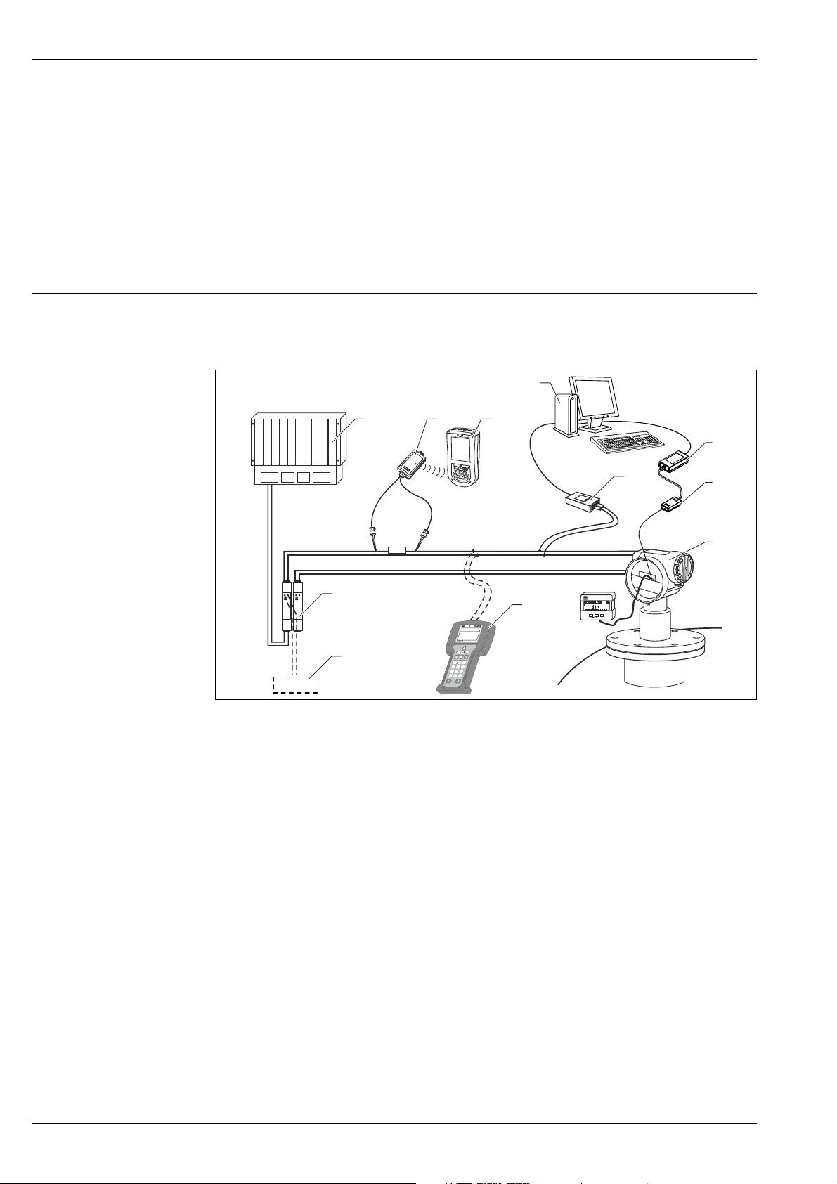
Equipment architecture Stand-alone
The device has a 4-20 mA output with HART protocol.
The complete measuring system consists of:
Micropilot S FMR540
A0020682
1 PLC (programmable logic controller)
2 VIATOR Bluetooth modem with connecting cable
3 Field Xpert
4 Computer with operating tool (e.g. FieldCare)
5 Commubox FXA291
6 ToF adapter FXA291
7 Commubox FXA195 (USB)
8 Micropilot with display module
9 Field Communicator 475
10 FXA195 or Field Communicator 475
11 Transmitter power supply unit RN221N (with communication resistor)
Local configuration
• with display and operating module VU331,
• with a Personal Computer, FXA291 with ToF Adapter FXA291 (USB) and the operating software
"FieldCare". FieldCare is a graphical operating software for devices from Endress+Hauser (radar,
ultrasonic, guided micro-impulse). It assists with commissioning, securing data, signal analysis and
documentation of the measuring point.
Remote configuration
• with Field Communicator 475
•with Field Xpert
• with a personal computer, Commubox FXA195 and "FieldCare" operating software
Remote operation
6 Endress+Hauser
With a Personal Computer, NRF590 (Tank Side Monitor) and the inventory management software.

Micropilot S FMR540
NXA820
NXA820
NXA820
16...253 VAC
1
2
3
9
8
7
4
5
6
Integration into the Asset Management System
The HART interface allows the integration into the AMS® (Asset Management System) from Emerson.
Custody transfer applications The Micropilot S is suitable for custody transfer and inventory control applications. The on-site testing
has to be done in compliance with the applicable regulatory standards. The Micropilot S can be sealed
after successful on-site calibration to be protected against any access to the electronics compartment
and any changes of software settings. If the Micropilot S is used for custody transfer or inventory
control, any temperature influence on the tank shell height can be compensated for using the Tank
Side Monitor. In addition, the vertical movement of the gauge reference point due to the hydrostatic
tank deformation can be compensated in the Tank Side Monitor. A Tank Side Monitor can provide 24 V
DC for a Micropilot S. The Tank Side Monitor can communicate with up to 6 devices via HART
Multidrop.
Integrated in tank gauging system
The Endress+Hauser Tank Side Monitor NRF590 provides integrated communications for sites with
multiple tanks, each with one or more sensors on th e tank, such as radar, spot or average temperature,
capacitive probe for water detection and/or pressure sensors. Multiple protocols out of the Tank Side
Monitor guarantee connectivity to nearly any of the existing industry standard tank gauging protocols.
Optional connectivity for 4-20 mA sensors, digital I/O and analog outputs facilitate full integration of
all sensors at the tank. Use of the proven concept of the intrinsically safe HART bus for all on-tank
sensors yields extremely low wiring costs, while at the same time providing maximum safety, reliability
and data availability.
A0020697
1 Tankvision workstation
2 Process control system
3Host Link
4 Micropilot S
5 Prothermo
6 Pressure transmitter
7Tank Side Monitor
8 Data Concentrator
9 Tankvision Tank Scanner NXA820
Endress+Hauser 7
Micropilot S FMR540
Input
Measured variable The measured variable is the distance between the reference point (GRH, refer to fig., ä 5) and a
reflective surface (i.e. medium surface). The measured value as well as all parameters can be displayed
in either metrical SI units or US/UK units (inch, ft, ….).
The level is calculated based on the tank height entered. The level can be converted into other units
(volume, mass) by means of a linearization. To compensate for non-linear effects such as movement
of the tank roof, a correction table (dip chart) can also be entered.
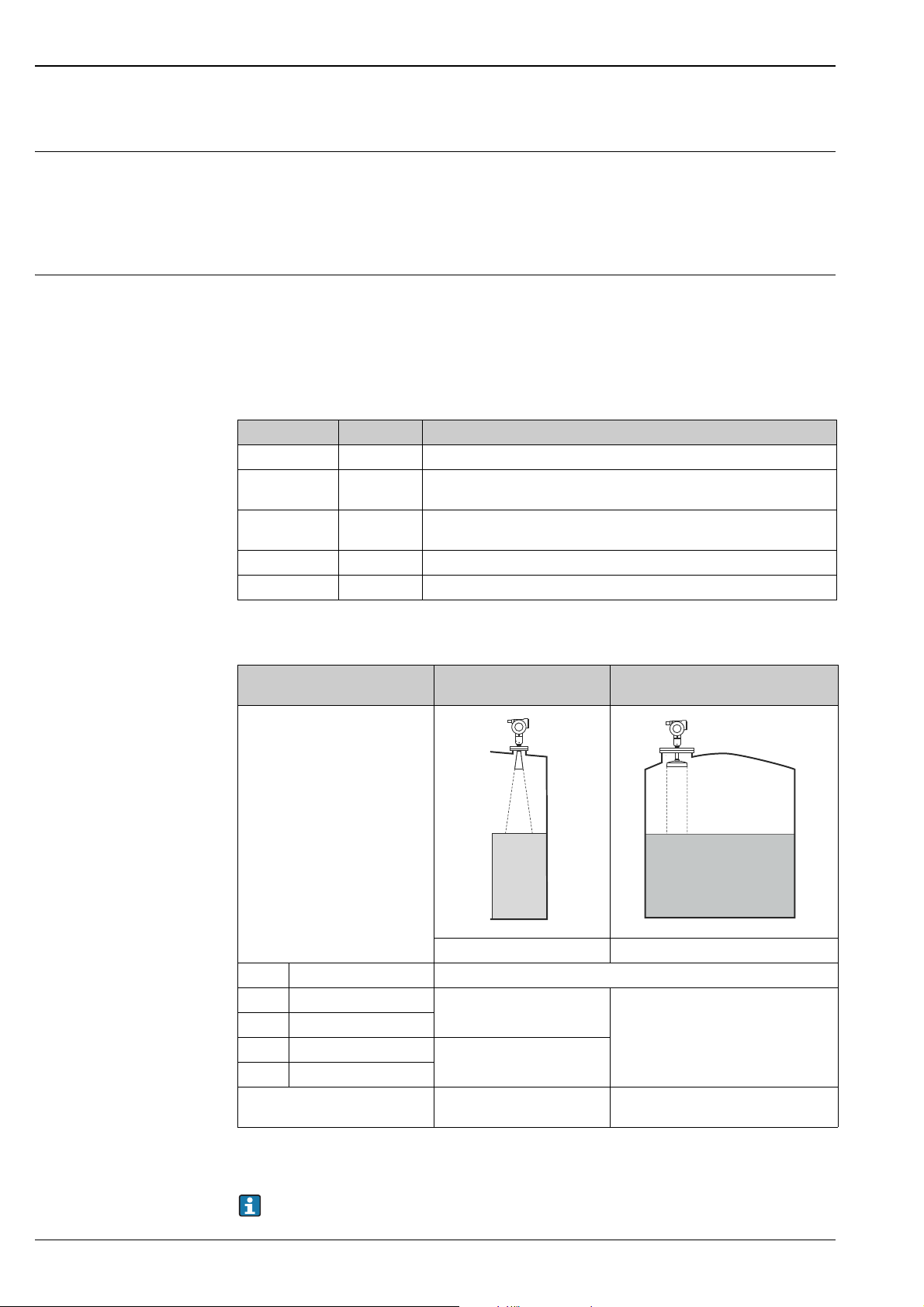
Measuring range The usable measuring range depends on the size of the antenna, the reflectivity of the medium, the
mounting location and possible interference reflections.
To achieve an optimised signal strength it is recommended to use an antenna with as large as possible
diameter (DN200 (8") or DN250 (10") parabolic antenna).
The following tables describe the groups of media as well as the achievable measuring range as a
function of application and media group. If the dielectric constant of the medium is unknown, we
recommend that you assume media group B, in order to ensure a reliable measurement.
Media group DC (r) Examples
A1 1.4 to 1.6 propane, butane
A2 1.6 to 1.9
B 1.9 to 4
C 4...10 e.g. concentrated acids, organic solvents, esters, aniline, alcohol, acetone, …
D > 10 Conducting liquids, e.g. aqueous solutions, diluted acids and alkalies
Non-conducting liquids, e.g. liquefied gas (LPG). For more information,
please contact your Endress+Hauser sales center.
Non-conducting liquids, e.g. gasoline, oil, toluene, white products, crude oil,
bitumen, asphalt …
Measuring range depending on sensor type and media group
Media group Horn antenna
without sensor extension
A0020821
Measuring range
A1 DC (r) = 1.4 to 1.6 Please contact your Endress+Hauser sales center.
A2 DC (
B DC (r) = 1.9 to 4
C DC (
D DC (
Max. measuring range with
custody transfer approval
r) = 1.6 to 1.9
r) = 4 to 10
r) > 10
0.6 to 20 m (2 to 66 ft)
0.6 to 30 m (2 to 98 ft)
NMi: 23 m (75 ft)
PTB: 23 (75 ft)
1)
Parabolic antenna
without sensor extension
Measuring range
0.6 to 40 m (2 to 131 ft)
NMi: 26 m (85 ft)
PTB: 30 m (98 ft)
1)
A0020822
1) All values are based on reference conditions.
For stilling well applications Micropilot S FMR532 is recommended (see TI01122F/00/EN).
8 Endress+Hauser

Micropilot S FMR540
Operating frequency K band (~ 26 GHz)
Up to 8 Micropilot devices can be installed in the same tank, as the transmitter pulses are statistically
coded.
Output
Output signal 4-20 mA (invertible) with HART protocol (e.g. for multi-drop connection to Tank Side Monitor
NRF590): This version can be operated using the PC and the operating software FieldCare. The device
supports both point-to-point and multidrop operation. For measurements with mm precision, the
measured value must be transmitted via HART protocol to ensure the necessary resolution.
Order code in Product Configurator under "Output; Operation" signal: Version A (4-line display VU331,
envelope curve display on site)
Signal on alarm Error information can be accessed via the following interfaces:
• Local display:
– Error symbol
– Plain text display
– LED’s: red LED continuously on = alarm, red LED flashes = warning
• Current output
• Digital interface
Load HART Minimum load for HART communication: 250
Linearization The linearization function of the Micropilot S allows the conversion of the measured value into any unit
of length or volume. Linearization tables for calculating the volume in cylindrical tanks are preprogrammed. Other tables of up to 32 value pairs can be entered manually or semi-automatically.
Galvanic isolation 500 V towards
• power supply and ground
• power supply and signal
Protocol specific data HART
Manufacturer ID 000011 hex
Device Type Code 001F hex
Transmitter-specific
revision
Device Revision 1 (for SW 01.01.00)
Features supported • Burst mode
DD-Files Actual information and files can be found:
Load HART Min. 250
Device variables Primary value: level or volume
01 hex
2 (for SW 01.01.02)
• Additional Transmitter Status
• www.endress.com
• www.hartcomm.org
1)
1) depending on configuration
Endress+Hauser 9
Power supply
112233445
5
16
20
24
28
17
21
25
29
18
22
26
30
19
23
27
31
p
--
--
-
-
++
++
+
+
H
12
3
4
H
H
OPT1D+S+D-S-
OPT2
OPT3
OPT4
4
3
6
A
B
1
2
5
Terminal assignment 4-20 mA with HART
The 4-wire cable is connected to the screw terminals (wire diameters 0.5 to 2.5 mm
[20 to 14 AWG]) in the terminal compartment. Use 4-wire twisted pair cable with screen for the
connection. Protective circuitry against reverse polarity, RFI, and over-voltage peaks is built into the
device (TI00241F/00/EN, "basics for EMC-tests").
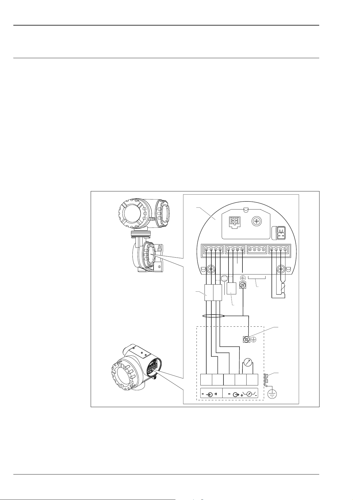
Connection to Tank Side Monitor NRF590
The Micropilot S may be connected, together with other devices in a hazardous area, to a Tank Side
Monitor. In this case, it is recommended that the shielding on the cables be grounded centrally at the
Tank Side Monitor and that all devices be connected to the same potential matching line (PML). If, for
functional reasons, a capacitive coupling is required between the local ground and the shield (multiple
grounding), ceramic capacitors with a minimum dielectric strength of 1500 Veff must be used. The
overall capacity of 10 nF must not be exceeded in this case. The FISCO model provides information on
grounding intrinsically safe, interconnected devices.
If it is not possible to lay a grounding cable between the NRF590 and the Micropilot S, it is possible to
ground on one side at the NRF590. In this case, it is essential that the cable shield on the Micropilot S
be grounded using a ceramic capacitor with a maximum capacitance of 10 nF and a minimum isolation
voltage of 1500 V.
Micropilot S FMR540
A Tank Side Monitor NRF590
B Micropilot S
1 For Micropilot S only
2 Intrinsically safe terminal strip
3 Shield, grounded on one side at Tank Side Monitor NRF590
4HART sensor
5Shielding cable
6 PML (potential matching line)
10 Endress+Hauser
A0020823

Micropilot S FMR540
E
112233445
5
G
A
B
D
F
C
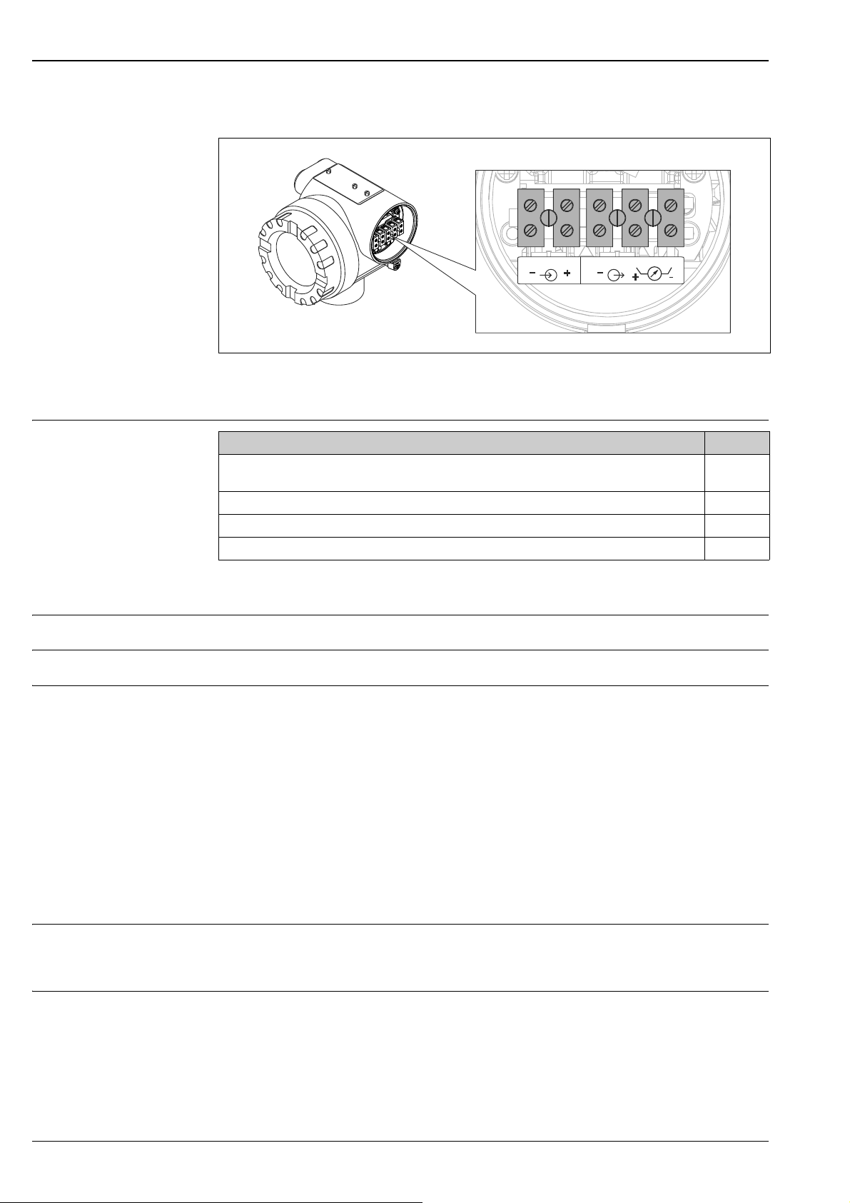
Connection as a stand-alone device
The Micropilot S located in a hazardous area is connected as a stand-alone device to a power supply
unit and transmitter located outside the hazardous area. In this case, it is recommended that the
shielding directly on the Micropilot be connected to the housing ground; the Micropilot S and the
supply unit are connected to the same potential matching line (PML).
A Power supply 24 VDC; provided by a supply unit
B Signal 24 VDC; provided by a supply unit
C Alternative connection
D Commubox FXA195, Field Communicator
EShielding cable
F Test socket; Output current
G PML (potential matching line)
Supply voltage DC voltage: see the following table
Communication Terminal voltage minimum maximum
Power supply
Signal Ex
Standard U (20 mA) = 16 V 36 V
Ex U (20 mA) = 16 V 30 V
Power consumption • max. 400 mW at 16 V
• max. 600 mW at 24 V
• max. 750 mW at 30 V
• Non-Ex: max. 900 mW at 36 V
Current consumption Max. 25 mA (55 mA inrush current).
A0020824
U (4 mA) = 11.5 V 30 V
U (20 mA) = 11.5 V 30 V
Endress+Hauser 11
Micropilot S FMR540
1
2
3
4
5
AB
Electrical connection The electronics and current output are galvanically isolated from the antenna circuit.
APower supply
BVoltage
A0020471
Cable entry
Designation Version*
Thread M20
Plastics M20x1.5 for cable 5 to 10 mm (0.2 to 0.39 in)
Cable gland M20 2
Thread for cable entry G ½" 3
Thread for cable entry NPT ½" 4
1
* Order code in Product Configurator ( ä 37)
Residual ripple HART 47 to 125 Hz: Upp = 200 mV
Max noise HART 500 Hz to 10 kHz : U
= 19 mV (at 500 )
eff
Overvoltage protection • The level transmitter Micropilot S is equipped with an internal overvoltage protector (600 Vrms
surge arrester) according to EN/IEC 60079-14 or EN/IEC 60060-1 (impulse current test 8/20 s, Î =
10 kA, 10 pulses). Additionally, the device is protected by a galvanic insulation of 500 Vrms between
the power supply and the (HART) current ouput. Connect the metallic housing of the Micropilot S to
the tank wall or shield directly using an electrically conductive lead to ensure reliable potential
matching.
• Installation with additional overvoltage protection HAW560Z/HAW562Z (see XA00081F, "Safety
instructions for electrical apparatus certified for use in explosion-hazardous areas").
– Connect the external overvoltage protector and the Micropilot S transmitter to the local potential
matching system.
– Potentials shall be equalised both inside and outside the explosion hazardous area.
– The length of the cable connecting the overvoltage protection and the Micropilot S level
transmitter must not exceed 1 m (3.3 ft).
– The cable must be protected e.g. routed through a metal tube.
Power supply • As a stand-alone version, power supply for example via two RN221N from Endress+Hauser.
• Integrated in tank gauging systems via Endress+Hauser Tank Side Monitor NRF590 (recommended
use).
Highly accurate measurement
12 Endress+Hauser
For highly accurate measurements the measured variable must be transmitted using HART protocol to
ensure the necessary resolution.
 Loading...