

Endress+Hauser FMR532 Operating Manual

BA00208F/00/EN/14.13
71229223
Valid as of software version
V 01.03.00 (amplifier)
V 01.03.00 (communication)
Products Solutions Services
Operating Instructions
Micropilot S FMR532
Level-Radar

Brief operating instructions
E
E
E
+
-
E
+
-
+
-
……
F
L
D
E
52006294
……
K
++
KA 161F/00/a2/12.01
52006294
- flat
ceiling
- stilling
well
…
- unknown
- <1.9
- 1.9 … 4
- 4 … 10
- >10
- standard
- calm
surface
- add. agitator
…
input E
(see sketch)
input F
(see sketch)
only for
bypass +
stilling well
- ok
- too small
- too big
- unknown
- manual
displayed
(see sketch)
D and L are
confirm
or specify
range
suggestion
000
measured value
Group
selection
00
basic setup
01
safety settings
03
mounting
calibr.
09
display
04
linearisation
05
extended calibr.
06
output
0C
system
parameters
092
language
0A
diagnostics
0A0
present
error
002
tank
shape
004
process
cond.
005
empty
calibr.
006
full
calibr.
007
pipe
diameter
008
dist./
meas value
009
history
reset
051
check
distance
003
medium
property
052
range of
mapping
053
start
mapping
008
dist./
meas value
flange:
referencepoint
of measurement
- envel. curve
- incl. FAC
- incl. cust. map
- single curve
- cyclic
= 100: unlocked
100: locked≠
09A
plot settings
09B
recording
curve
0A1
previous
error
0A4
unlock
parameter
- dip table
- auto correct.
030
tank
gauging
033
dip table
mode
034/035
dip table
555 = Histor y Reset
(333 = reset customer parameters)
0A3
reset
basic setup
dip tab le
offsetfirst point corrects
further points correct linearity
histor y reset (= 555)
Contrast: or
Micropilot S - Quick Setup
This operating manual explains the installation and initial start-up for the level
transmitter. All functions that are required for a typical measuring task are taken into
account here. In addition, the Micropilot S provides many other functions that are not
included in this operating manual, such as optimising the measuring point and
converting the measured values.
An overview of all device functions can be found on ä 82.
The operating manual BA00217F/00/EN "Description of Instrument Functions"
provides an extensive description of all device functions, which can be found on the
enclosed CD-ROM.
The Operating Instructions can also be found on our homepage: www.endress.com
A0021144-EN
Endress+Hauser

Micropilot S FMR532 4 to 20 mA HART
Table of Contents
1 Safety instructions . . . . . . . . . . . . . . . . . . 4
1.1 Designated use . . . . . . . . . . . . . . . . . . . . . . . . . . . . . 4
1.2 Installation, commissioning and operation . . . . . . 4
1.3 Operational safety and process safety . . . . . . . . . . 4
1.4 Notes on safety conventions and symbols . . . . . . . 5
2 Identification . . . . . . . . . . . . . . . . . . . . . . 7
2.1 Device designation . . . . . . . . . . . . . . . . . . . . . . . . . . 7
2.2 Scope of delivery . . . . . . . . . . . . . . . . . . . . . . . . . . . . 9
2.3 Certificates and approvals . . . . . . . . . . . . . . . . . . . . 9
2.4 Registered trademarks . . . . . . . . . . . . . . . . . . . . . . . 9
3 Mounting. . . . . . . . . . . . . . . . . . . . . . . . . 10
3.1 Quick installation guide . . . . . . . . . . . . . . . . . . . . 10
3.2 Incoming acceptance, transport, storage . . . . . . 10
3.3 Installation Conditions . . . . . . . . . . . . . . . . . . . . . 11
3.4 Installation instructions . . . . . . . . . . . . . . . . . . . . 14
3.5 Post-installation check . . . . . . . . . . . . . . . . . . . . . 23
4 Wiring . . . . . . . . . . . . . . . . . . . . . . . . . . . 24
4.1 Quick wiring guide . . . . . . . . . . . . . . . . . . . . . . . . 24
4.2 Connecting the measuring unit . . . . . . . . . . . . . . 26
4.3 Recommended connection . . . . . . . . . . . . . . . . . . 29
4.4 Degree of protection . . . . . . . . . . . . . . . . . . . . . . . 29
4.5 Post-connection check . . . . . . . . . . . . . . . . . . . . . 29
8 Accessories. . . . . . . . . . . . . . . . . . . . . . . 71
8.1 Weather protection cover . . . . . . . . . . . . . . . . . . . 71
8.2 Commubox FXA195 HART . . . . . . . . . . . . . . . . . . 71
8.3 Commubox FXA291 . . . . . . . . . . . . . . . . . . . . . . . . 71
8.4 ToF Adapter FXA291 . . . . . . . . . . . . . . . . . . . . . . . 71
8.5 Field Xpert . . . . . . . . . . . . . . . . . . . . . . . . . . . . . . . . 71
8.6 Mounting with Sample hatch on stilling well . . . 72
9 Trouble-shooting . . . . . . . . . . . . . . . . . 73
9.1 Trouble-shooting instructions . . . . . . . . . . . . . . . . 73
9.2 System error messages . . . . . . . . . . . . . . . . . . . . . 74
9.3 Application errors . . . . . . . . . . . . . . . . . . . . . . . . . . 76
9.4 Spare parts . . . . . . . . . . . . . . . . . . . . . . . . . . . . . . . . 78
9.5 Return . . . . . . . . . . . . . . . . . . . . . . . . . . . . . . . . . . . 78
9.6 Disposal . . . . . . . . . . . . . . . . . . . . . . . . . . . . . . . . . . 79
9.7 Software history . . . . . . . . . . . . . . . . . . . . . . . . . . . 79
9.8 Contact addresses of Endress+Hauser . . . . . . . . . 79
10 Technical data . . . . . . . . . . . . . . . . . . . . 80
10.1 Additional technical data . . . . . . . . . . . . . . . . . . . . 80
10.2 Supplementary Documentation . . . . . . . . . . . . . . 80
11 Appendix . . . . . . . . . . . . . . . . . . . . . . . . 82
11.1 Operating menu HART (Display modul) . . . . . . . 82
11.2 Integrated in tank gauging system . . . . . . . . . . . . 84
5 Operation. . . . . . . . . . . . . . . . . . . . . . . . . 30
5.1 Quick operation guide . . . . . . . . . . . . . . . . . . . . . 30
5.2 Display and operating elements . . . . . . . . . . . . . 32
5.3 Local operation . . . . . . . . . . . . . . . . . . . . . . . . . . . 35
5.4 Display and acknowledging error messages . . . 38
5.5 HART communication . . . . . . . . . . . . . . . . . . . . . 39
6 Commissioning. . . . . . . . . . . . . . . . . . . . 42
6.1 Function check . . . . . . . . . . . . . . . . . . . . . . . . . . . 42
6.2 Switching on the measuring device . . . . . . . . . . 42
6.3 Basic Setup . . . . . . . . . . . . . . . . . . . . . . . . . . . . . . . 43
6.4 Basic Setup with the device display VU331 . . . . 45
6.5 Mounting calibration
with device display VU331 . . . . . . . . . . . . . . . . . 54
6.6 Basic Setup with the
Endress+Hauser operating program . . . . . . . . . . 64
6.7 Mounting calibration with the
Endress+Hauser operating program . . . . . . . . . . 68
7 Maintenance. . . . . . . . . . . . . . . . . . . . . . 70
7.1 Exterior cleaning . . . . . . . . . . . . . . . . . . . . . . . . . . 70
7.2 Replacing seals . . . . . . . . . . . . . . . . . . . . . . . . . . . 70
7.3 Repair . . . . . . . . . . . . . . . . . . . . . . . . . . . . . . . . . . . 70
7.4 Repairs to Ex-approved devices . . . . . . . . . . . . . . 70
7.5 Replacement . . . . . . . . . . . . . . . . . . . . . . . . . . . . . 70
Index . . . . . . . . . . . . . . . . . . . . . . . . . . . . 85
Endress+Hauser 3

Safety instructions Micropilot S FMR532 4 to 20 mA HART
CAUTION
!
1 Safety instructions
1.1 Designated use
The Micropilot S is a compact radar level transmitter for the continuous, contactless
measurement of liquids. The device can also be freely mounted outside closed metal vessels
because of its operating frequency of about 6 GHz and a maximum radiated pulsed energy
of 1 mW (average power output 1 μW). Operation is completely harmless to humans and
animals.
1.2 Installation, commissioning and operation
The Micropilot S has been designed to operate safely in accordance with current technical,
safety and EU standards. If installed incorrectly or used for applications for which it is not
intended, however, it is possible that application-related dangers may arise, e.g. product
overflow due to incorrect installation or calibration. For this reason, the device must be
installed, connected, operated and maintained according to the instructions in this manual:
personnel must be authorised and suitably qualified. The manual must have been read and
understood, and the instructions followed. Modifications and repairs to the device are
permissible only when they are expressly approved in the manual.
1.3 Operational safety and process safety
Alternative monitoring measures must be taken to ensure operational safety and process
safety during configuration, testing and maintenance work on the device.
1.3.1 Hazardous areas
Measuring systems for use in hazardous environments are accompanied by separate "Ex
documentation", which is an integral part of this Operating Manual. Strict compliance with
the installation instructions and ratings as stated in this supplementary documentation is
mandatory.
• Ensure that all personnel are suitably qualified.
• Observe the specifications in the certificate as well as national and local regulations.
1.3.2 FCC approval
This device complies with part 15 of the FCC Rules. Operation is subject to the following two
conditions:
1. This device may not cause harmful interference, and
2. this device must accept any interference received, including interference that may cause
undesired operation.
Changes or modifications not expressly approved by the part responsible for
compliance could void the user’s authority to operate the equipment.
4 Endress+Hauser
Micropilot S FMR532 4 to 20 mA HART Safety instructions
1.4 Notes on safety conventions and symbols
In order to highlight safety-relevant or alternative operating procedures in the manual, the
following conventions have been used, each indicated by a corresponding symbol in the
margin.
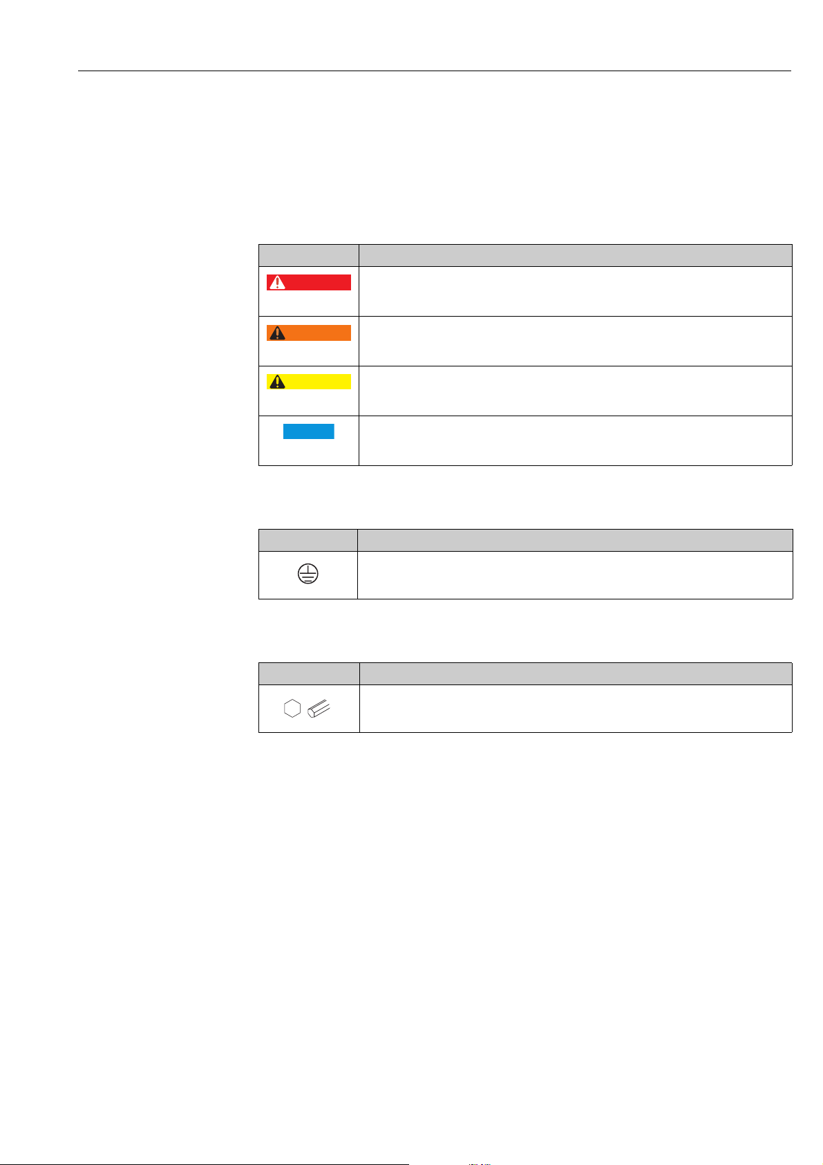
1.4.1 Safety symbols
Symbol Meaning
DANGER
A0011189-EN
WARNING
A0011190-EN
CAUTION
A0011191-EN
NOTICE
A0011192-EN
DANGER!
This symbol alerts you to a dangerous situation. Failure to avoid this situation will result in
serious or fatal injury.
WARNING!
This symbol alerts you to a dangerous situation. Failure to avoid this situation can result in
serious or fatal injury.
CAUTION!
This symbol alerts you to a dangerous situation. Failure to avoid this situation can result in
minor or medium injury.
NOTICE!
This symbol contains information on procedures and other facts which do not result in
personal injury.
1.4.2 Electrical symbols
Symbol Meaning
Protective ground connection
A terminal which must be connected to ground prior to establishing any other connections.
A0018339
1.4.3 Tool symbols
Symbol Meaning
Allen key
A0011221
Endress+Hauser 5

Safety instructions Micropilot S FMR532 4 to 20 mA HART
1.4.4 Symbols for certain types of information
Symbol Meaning
Allowed
Indicates procedures, processes or actions that are allowed.
A0011182
Forbidden
Indicates procedures, processes or actions that are forbidden.
A0011184
Tip
Indicates additional information.
A0011193
Reference to page
Refers to the corresponding page number.
A0015484
, , ,... Series of steps
1.4.5 Symbols in graphics
Symbol Meaning
1, 2, 3, 4, ... Item numbers
, , ,... Series of steps
A, B, C, D, ... Views
1.4.6 Symbols at the device
Symbol Meaning
Safety instructions
Observe the safety instructions contained in the associated Operating Instructions.
A0019159
Temperature resistance of the connection cables
Specifies the minimum value of the temperature resistance of the connection cables.
A0019221
6 Endress+Hauser
Micropilot S FMR532 4 to 20 mA HART Identification
ENDRESS+HAUSER
Ser.-No.:
Order Code:
MICROPILOT S
TA > 70°C:
Dat./Insp.:
D00676-F
x =
0032
0560
Made in Germany
79689 Maulburg
PN max.
Antenne
Anschlusswerte u. Temp.-Klasse siehe/
Connection values and temp.-classic. see
T max. °C
if modification
see sep. label
t >85°C
1
3
54
6
7
8
9
10
11
12
2
Messbereich
Measuring range
max.
ENDRESS+HAUSER
MICROPILOT S FMR
Hersteller / Producer :
Zert.Messbereich/Cert.Measuring range
Umgeb./Environm.
bis
to
min
max
von
from
Baujahr
Year of constr.
Zertifikat-Nr.
Certification no.
T
m
°C
D00748-C
Tank-Nr.
Tank-no.
Tankreferenzhöhe
Tank reference height
m
1
2
3
4
5
56
7
2 Identification
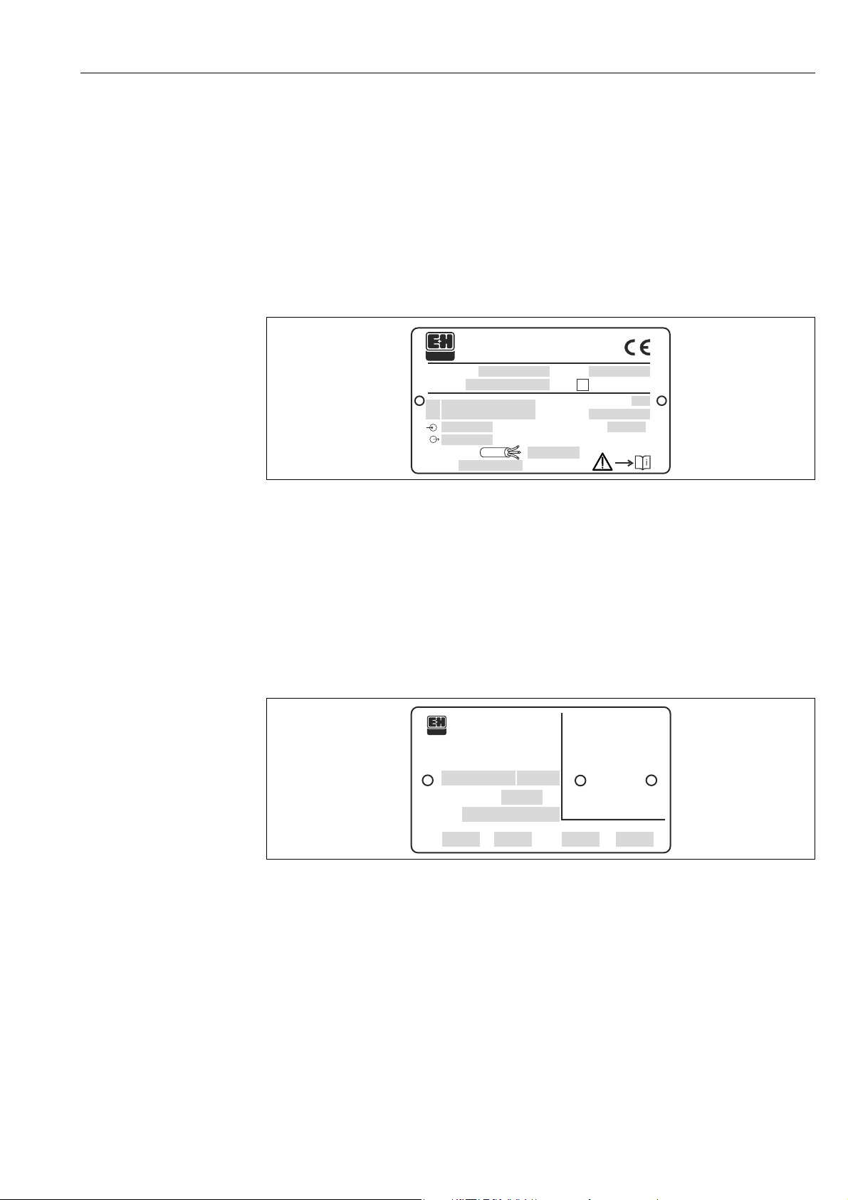
2.1 Device designation
2.1.1 Nameplate
Device nameplate
The following technical data are given on the device nameplate:
1Order code
2 Degree of protection e.g. IP65, IP67
3 Serial number
4 Certificate symbol (optional) e.g. Ex
5 Approval number and type of protection
6Max. measuring range
7 Max. permissible pressure in tank
8 Max. permissible temperature on the antenna
9Power supply
10 Current supply
11 Safety infromation (Connection values and temp.-classific.)
12 Dat.Insp. xx/yy (xx = week of production, yy = year of production)
NMI type plate
Note!
The fields are only filled if in feature "70" "Weight + measures approval" the variant "F" is selected.
1 Certificate number
2Year of construction
3 Tank reference height
4Tank number
5 Certificated measuring range from ... to ...
6 Min. environment temperature
7 Max. environment temperature
A0020445
A0020413
Endress+Hauser 7

Identification Micropilot S FMR532 4 to 20 mA HART
ENDRESS+HAUSER
MICROPILOT S FMR
Hersteller / Producer :
Tank-Nr.
Tank-no.
Baujahr
Year of constr.
Tankreferenzhöhe
Tank reference height
m
D00549-B
Zert.Messbereich/Cert.Measuring range
Umgeb./Environm.
bis
to
min
max
von
from
T
m
°C
1
2
3
4
5
66 7 8
PTB type plate
A0020446
Note!
The fields are only filled if in feature "70" "Weight + measures approval" the variant "G" is selected.
1 Approval number
2 Year and month of type approval
3 Year of construction
4 Tank reference height
5Tank number
6 Certificated measuring range from ... to ...
7 Min. environment temperature
8 Max. environment temperature
8 Endress+Hauser

Micropilot S FMR532 4 to 20 mA HART Identification
CAUTION
!
2.2 Scope of delivery
It is essential to follow the instructions concerning the unpacking, transport and
storage of measuring devices given in the chapter "Incoming acceptance, transport,
storage", ä 10!
The scope of delivery consists of:
• Assembled device
• Accessories ( ä 71)
•2 seals
• Endress+Hauser operating program on the enclosed CD-ROM
• Brief operating instructions KA01057F/00/EN for quick commissioning
• Brief operating instructions KA00161F/00/A2 (basic setup/troubleshooting), housed in
the device
• Approval documentation: if this is not included in the operating manual
• CD-ROM with further documentation, e.g.
– Operating Instructions
– Description of Instrument Functions
2.3 Certificates and approvals
CE mark, declaration of conformity
The device is designed to meet state-of-the-art safety requirements, has been tested and left
the factory in a condition in which it is safe to operate. The device complies with the
applicable standards and regulations as listed in the EC declaration of conformity and thus
complies with the statutory requirements of the EG directives. Endress+Hauser confirms the
successful testing of the device by affixing to it the CE mark.
2.4 Registered trademarks
KALREZ®, VITON®, TEFLON
Registered trademark of the company, E.I. Du Pont de Nemours & Co., Wilmington, USA
TRI-CLAMP
®
Registered trademark of the company, Ladish & Co., Inc., Kenosha, USA
®
HART
Registered trademark of HART Communication Foundation, Austin, USA
®
ToF
Registered trademark of the company Endress+Hauser GmbH+Co. KG, Maulburg, Germany
PulseMaster
®
Registered trademark of the company Endress+Hauser GmbH+Co. KG, Maulburg, Germany
PhaseMaster
®
Registered trademark of the company Endress+Hauser GmbH+Co. KG, Maulburg, Germany
FieldCare
®
Registered trademark of the Endress+Hauser Process Solutions AG, Reinach, Switzerland
®
Endress+Hauser 9
Mounting Micropilot S FMR532 4 to 20 mA HART
CAUTION
!
90°
.
.
3Mounting
3.1 Quick installation guide
3.1.1 Installation only in stilling well
A0021216
The performance of the planar antenna is not dependent on the alignment or
geometry of standard stilling wells. No special alignment is required. However, make
sure that the planar antenna is installed vertically relative to the stilling well axis.
3.2 Incoming acceptance, transport, storage
3.2.1 Incoming acceptance
Check the packing and contents for any signs of damage. Check the shipment, make sure
nothing is missing and that the scope of supply matches your order.
3.2.2 Transport
Follow the safety instructions and transport conditions for devices of more than
18 kg (39.69 lbs).
3.2.3 Storage
Pack the measuring device so that is protected against impacts for storage and transport.
The original packing material provides the optimum protection for this.
The permissible storage temperature is -40 to +80 °C (-40 to +176 °F).
10 Endress+Hauser

Micropilot S FMR532 4 to 20 mA HART Mounting
BD
SD
A
100%
0%
B
C
1
3.3 Installation Conditions
3.3.1 Engineering hints
Measuring conditions
• The measuring range begins where the beam hits the tank bottom. Particularly with dish
bottoms or conical outlets the level cannot be detected below this point.
•For overfill prevention, it is possible to define a safety distance (SD) additionally to the
blocking distance (BD).
• Depending on its consistence, foam can either absorb microwaves or reflect them off the
foam surface. Measurement is possible under certain conditions.
• The smallest possible measuring range B depends on the antenna version (see Fig.).
• The zero should be positioned at the end of the tube, as the electromagnetic waves do not
propagate completely outside the tube. It must be taken into account that the accuracy
may be reduced in the area C. In order to guarantee the required accuracy in these cases,
it is recommended to position the zero-point at a distanc C above the tank bottom (see
Fig.).
• In applications with planar antennas, especially for media with low dielectric constants
(media group A and B, ä 12), the end of the measuring range should not be closer than
1 m (3.3 ft) to the flange (cf. A in following figure).
• The safety distance (SD) is set to 0.5 m (1.6 ft) by default, generating an alarm in case the
product level rises inside the safety distance.
A0020735
1Max. level
Reference: flange / BD (cf. picture) Reference: antenna tip (cf. picture)
Blocking distance Safety distance Recommended additional settings
BD [m (ft)] SD [m (ft)] A [mm (in)] B [m (ft)] C [mm (in)]
1 (3.3) 0,5 (1.6) 1000 (39.4) 0,5 (1.6)
150 to 300
(5.91 to 11.8)
Behaviour if measuring range is exceeded
The behaviour in case of the measuring range being exceeded can be freely set:
The default setting is a current of 22 mA and the generation of a digital warning (E681).
Endress+Hauser 11

Mounting Micropilot S FMR532 4 to 20 mA HART
Measuring range
The usable measuring range depends on the size of the antenna, the reflectivity of the
medium, the mounting location, and eventual interference reflections.
The following tables describe the groups of media as well as the achievable measuring range
as a function of application and media group. If the dielectric constant of a medium is
unknown, it is recommended to assume media group B to ensure a reliable measurement.
Media group DC (r) Examples
A 1.4 to 1.9
B 1.9 to 4
C 4 to 10 E.g. concentrated acids, organic solvents, esters, aniline, alcohol, acetone, …
D > 10 Conducting liquids, e.g. aqueous solutions, dilute acids and alkalis
Non-conducting liquids, e.g. liquefied gas (LPG). For more information please
contact your Endress+Hauser representative.
Non-conducting liquids, e.g. benzene, oil, toluene, white products, black
products, crudes, bitumen/asphalts, …
Measuring range depending on product class
Media group Stilling well/ Bypass
A DC (
max. measuring range with
custody transfer approvals
r) = 1.4 to 1.9
B DC (r) = 1.9 to 4
r) = 4 to 10
C DC (
r) > 10
D DC (
A0020746
Measuring range
FMR532 DN 150
38 m (125 ft)
NMi: 25 m (82 ft)
PTB: 30 m (98 ft)
12 Endress+Hauser
Micropilot S FMR532 4 to 20 mA HART Mounting
NOTICE
20 mA
100%
BD
A
B
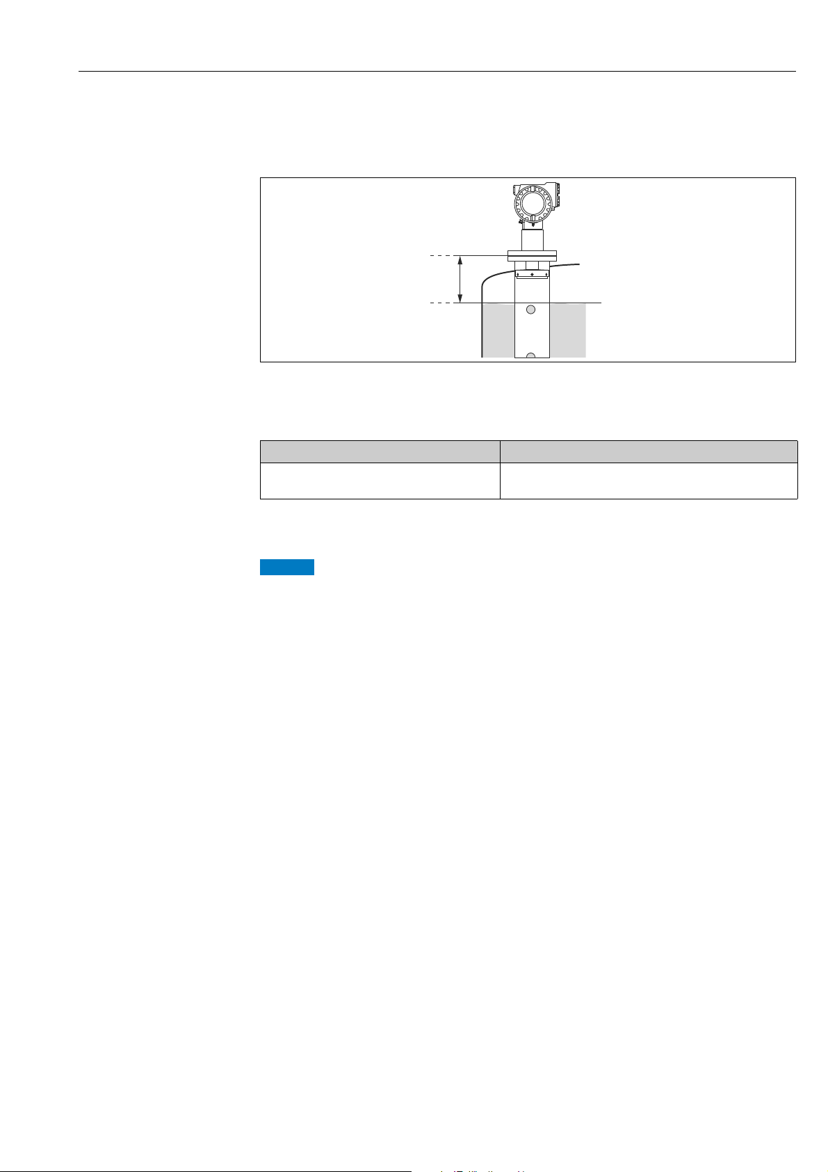
Blocking distance
The blocking distance (= BD) is the minimum distance from the reference point of the
measurement (mounting flange) to the medium surface at maximum level.
A0021842
A Reference point of measurement
B Maximum level
Blocking distance (BD)
from flange 1 m (3.3 ft)
1) 1 mm accuracy under reference conditions
1)
(see chapter "Mechanical construction" in TI01122F/00/EN)
Free space (Storage tank)
Inside the blocking distance a reliable measurement can not be guaranteed.
Endress+Hauser 13

Mounting Micropilot S FMR532 4 to 20 mA HART
BBAA
1111
90°
3.4 Installation instructions
3.4.1 Mounting kit
For the mounting, you will require the following tool:
• The tool for flange mounting
• 4 mm (0.1") Allen wrench for turning the housing
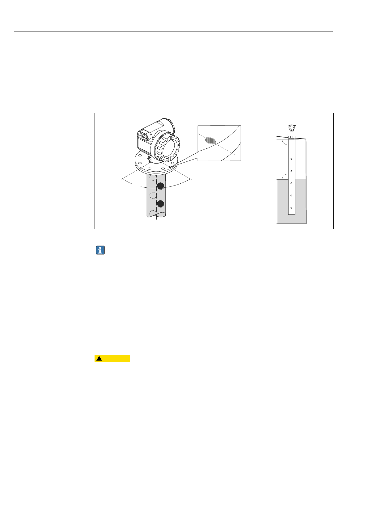
3.4.2 Installation in tank (stilling well)
Optimum mounting position
A0021159
1 Marker at instrument flange
A DN 150, ANSI 6"
B DN 200 to 250, ANSI 8 to 10"
Standard installation
• Observe installation instructions, ä 11.
• After mounting, the housing can be turned 350° in order to simplify access to the display
and the terminal compartment.
• Planar axis vertical to flange.
• Measurements can be performed through an open ball valve without any problems.
14 Endress+Hauser

Micropilot S FMR532 4 to 20 mA HART Mounting
NOTICE
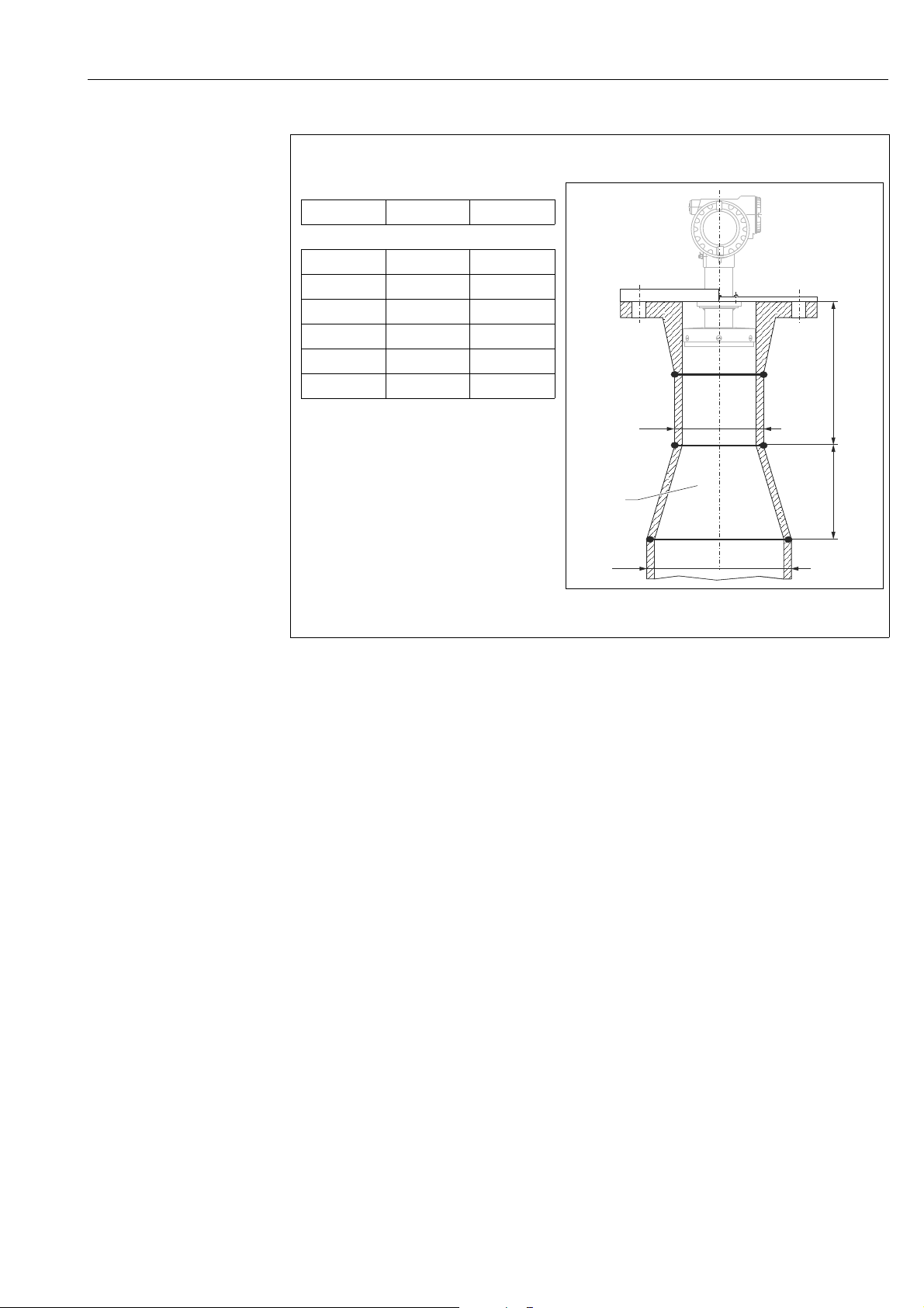
Recommendations for the stilling well
• Metal (no enamel coating, plastic on request).
• Constant diameter.
• When using a FMR532, an increase of the pipe diameter from DN 150 to DN 200 /
DN 200 to DN 250 / DN 250 to DN 300 is acceptable. A larger step-width for the increase
of the pipe diameter (e.g. DN 150 to DN 300) is possible if the upper part of the pipe has
a suitable length. The length of the stilling well enlargement must be kept. In this case, the
upper end of the pipe must have a minimum length of 0.5 m (1.6 ft) before the diameter
increases (refer to table, ä 16). If the length is less than "L", please contact
Endress+Hauser in order to determine a suitable antenna adapter (separable antenna
horn). Ideally, a sample hatch is used.
• Any rectangular increase of the pipe diameter has to be avoided.
• Weld seam as smooth as possible and on the same axis as the slots.
• For best radar propagation behavior holes it is recommended to have holes instead of slots.
If slots can not be avoided, they should be as thin and short as possible.
• The diameter of the holes (deburred) can be up to 1/7 of the pipe diameter but should not
exceed 30 mm (1.18 in).
• Length and number of the holes do not affect the measurement.
• Maximum gap allowed between the antenna/horn and the inside of the stilling well is
5 mm (0.2 in).
• At any transition (e.g. when using a ball valve or mending pipe segments), no gap may be
created exceeding 1 mm (0.04 in).
• The stilling well must be smooth on the inside. Use extruded or parallel welded steel pipe.
An extension of the pipe is possible with welded flanges or pipe sleeves. Flange and pipe
have to be properly aligned at the inside.
• Do not weld through the pipe wall. The inside of the stilling well must remain smooth. In
case of unintentional welding through the pipe, the weld seam and any unevenness on the
inside need to be carefully removed and smoothed. Otherwise, strong interference echoes
will be generated and material build-up will be promoted.
Selection of antenna size
‣ Select antenna extension as big as possible. For intermediate sizes
(e.g. 180 mm (7.09 in)) select next larger antenna extension and adapt it mechanically.
Maximum gap allowed between the antenna/horn and the inside of the stilling well is
5 mm (0.2 in).
‣ The antenna extension of the FMR532 is mounted with defined pressure.
It is strongly recommended not to dismantle this antenna.
‣ Dimensions of a nozzle for manual gauging must be adapted to the dimensions of the
horn antenna used, compare ä 16.
Endress+Hauser 15

Mounting Micropilot S FMR532 4 to 20 mA HART
100 %
100 %
AB
<1/7
8
5
4
3
2
6
1
1 (0.04)≤
7
≤5 (0.2)
Examples for the construction of stilling wells
Dimensions: mm (in)
A Installation in stilling well
B Installation in stilling well with sample hatch
1 <1/7 pipe diameter
2 Gap <5 mm (0.2 in)
3Weld-neck flange
4 Flange (DIN, ANSI, JIS, JPI)
5 Micropilot S FMR532
6 Endress+Hauser UNI flange
7 Gap <1 mm (0.04 in)
8Sample hatch
A0020747
16 Endress+Hauser
Micropilot S FMR532 4 to 20 mA HART Mounting
øD1
øD2
L
500 (19.7)
1
For retrofit of mechanical sysstems recommended
increase of diameter:
D1 D2 L
150 (5.91) 200 (7.87) 300 (11.8)
150 (5.91) 250 (9.84) 300 (11.8)
150 (5.91) 300 (11.8) 450 (17.7)
200 (7.87) 250 (9.84) 300 (11.8)
200 (7.87) 300 (11.8) 450 (17.7)
250 (9.84) 300 (11.8) 450 (17.7)
Dimensions: mm (in)
A0020786
Endress+Hauser 17
Mounting Micropilot S FMR532 4 to 20 mA HART
4 mm
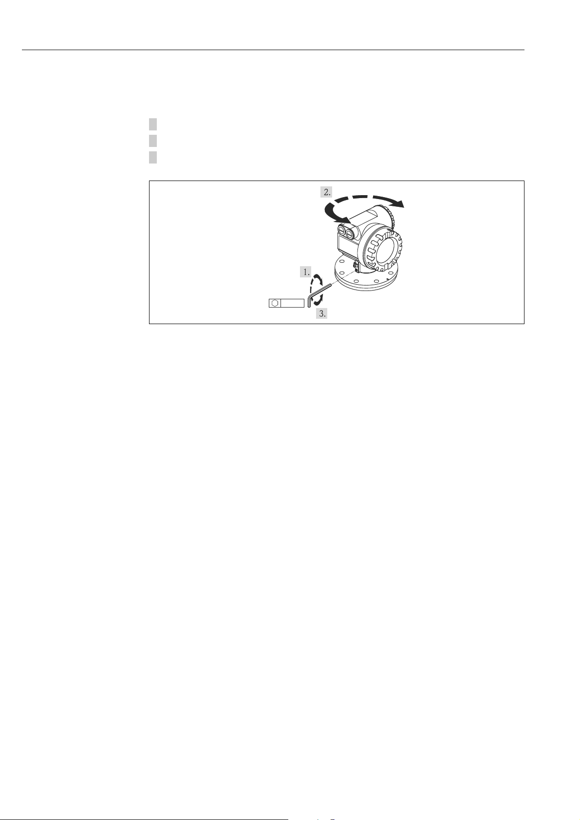
3.4.3 Turn housing
After mounting, the housing can be turned 350° in order to simplify access to the display and
the terminal compartment. Proceed as follows to turn the housing to the required position:
1. Undo the allen screw
2. Turn the housing in the required direction
3. Tighten up the allen screw strongly by hand
A0020470
18 Endress+Hauser

Micropilot S FMR532 4 to 20 mA HART Mounting
øK
øD
ø23 (0.91)
ø12 (0.47)
øK
60°
90°
15°
øD
ø26 (1.02)
ø78 (3.07)
ø101 (3.98)
øK
øD
ø29 (1.14)
30°
A
A
A-A
1 (0.04)
8 (0.31)
3
1
2
ø63.2 (2.49)
B
D
C
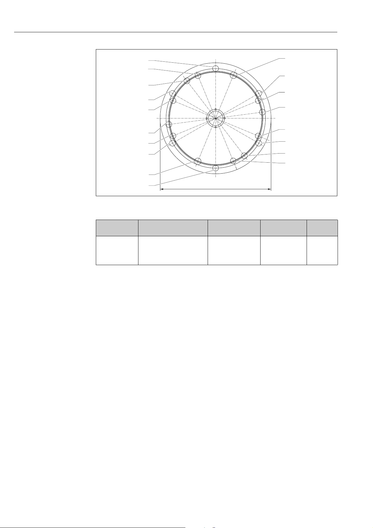
3.4.4 Installation with Endress+Hauser UNI flange
Installation hints
Endress+Hauser UNI flanges are designed for non-pressurized operation respectively
max. 1 bar (14.5 psi) absolute pressure. The number of bolts has sometimes been reduced.
The bolt-holes have been enlarged for adaption of dimensions, therefore, the flange needs
to be properly aligned to the counterflange before the bolts are tightened.
Endress+Hauser UNI flange. Dimensions: mm (in).
1 4 x ø7 mm (0.28 in) moved 90°
2 Sealing surface
3 For small bolts
UNI
Flange
B • DN150 PN16
C • DN200 PN16
D • DN250 PN16
Compatible with øD (mm [in]) øK (mm [in]) Type plate Material
• ANSI 6" 150lbs
• JIS 10K 150
• ANSI 8" 150lbs
• JIS 10K 200
• ANSI 10" 150lbs
• JIS 10K 250
A0021069
280 (11,0) 240 (9,45) 942455-3001
340 (13,4) 294,5 (11,6) 942455-3002
1.4301
405 (15,9) 358 (14,1) 942455-3003
Endress+Hauser 19
Mounting Micropilot S FMR532 4 to 20 mA HART
0°
2 [0°]
4 [22.5°]
2 [60°]
1 [67.5°]
3 [82.5°]
1 [112.5°]
2 [120°]
3 [142.5°]
1 [157.5°]
2 [180°]
4 [202.5°]
2 [240°]
1 [247.5°]
3 [262.5°]
1 [292.5°]
3 [322.5°]
1 [337.5°]
2 [300°]
ø482 (19) ±1.5
A0021069
Endress+Hauser UNI flange. Dimensions: mm (in).
Position Bolt circle diameter øK
1: for JIS
2: for ANSI
3: for DIN
4: for DIN+JIS
[mm (in)]
ø25 (0,98): 400 (15.7)
ø26 (1,02): 431.8 (17)
ø26* (1,02): 410 (16.1)
ø29 (1,14): 404.5 (15.9)
Compatible with Type plate Material
• DN300 PN16
• ANSI 12" 150lbs
•JIS 10K 300
942455-3004 1.4301
20 Endress+Hauser

Micropilot S FMR532 4 to 20 mA HART Mounting
CAUTION
!
Made in Germany MaulburgMade in Germany Maulburg
ENDRESS+HAUSER
MICROPILOT
II
ENDRESS+HAUSER
MICROPILOTII
IP65IP 65
Order Code:
Ser.-No.:
Order Code:
Ser.-No.:
Messbereich
Measuringrange
Messbereich
Measuringrange
U 16...36 V DC
4...20 mA
U 16...36 V DC
4...20 mA
max.20 mmax. 20 m
T >70°C :
A
t >85°C
T >70°C :
A
t >85°C
ENDRESS+HAUSER
Preparation for the installation of the Endress+Hauser UNi flange
The mounting requires the following tools:
• Philips screw driver size 1
• Flat screw driver for M3/M4
• Hexagon key AF2.5/AF4
• Unplug tool for antenna plug (order nr.: 52007646)
• Eventually a pair of tweezers
A0021218
Order of exchange:
1. Unscrew lid from terminal compartment.
2. Disconnect cable at terminal module. Unscrew mounting screws at terminal module and
disconnect ground cable. Pull out terminal module. A connection to a cable feed-through
is located at the rear side of the module (the feed-through can be unscrewed, if required).
3. Unscrew lid from electronics compartment.
4. If installed, take display out of holder by pushing the hook upwards. Break the calibration
seal to unplug the sealing pin.
If the calibration seal is broken, the national calibration authority should be informed
within 24 hours.
Endress+Hauser 21

Mounting Micropilot S FMR532 4 to 20 mA HART
CAUTION
!
ENDRESS+HAUSER
ENDRESS+HAUSER
1x
5x
Pull front panel off.
Unplug display cable.
Loosen screw in cover and remove cover.
Loosen mounting screws at electronics
housing.
Pull electronics module out of the
housing. Unplug connection cable (right)
to the terminal module from the
electronics. Unplug antenna cable (left)
with unplug tool.
Don’t damage the antenna cable.
Press lower hook at module housing
slightly inwards.
Loosen the set screw in the housing about
1 turn. (Hexagon key AF4)
Unscrew the stop screw in the housing
about 4-5 turns. (Hexagon key AF2.5)
While turning the complete antenna
assembly, pull it out of the housing.
22 Endress+Hauser
A0021252

Micropilot S FMR532 4 to 20 mA HART Mounting
9 (0.35)
ø78 (3.07)
ø62.5 (2.46)
ø99.5 (3.92)
4
3
2
A
1
A Flange hub for the connection to flanges provided by the customer
1 Endress+Hauser UNI flange (max. 1 bar (14.5 psi))
1 Mounting: 4 bolts M6 / 90°; e.g.: DIN912
2 O-Ring 85.3x3.53; included (same material as sensor seal)
3Flange hub
The mounting of the housing and electronic raised last in - first out how disassembly.
3.5 Post-installation check
After the measuring device has been installed, perform the following checks:
• Is the measuring device damaged (visual check)?
• Does the measuring device correspond to the measuring point specifications such as
process temperature/pressure, ambient temperature, measuring range, etc.?
• Is the flange marking correctly aligned ( ä 10)?
• Have the flange screws been tightened up with the respective tightening torque?
• Are the measuring point number and labeling correct (visual check)?
• Is the measuring device adequately protected against rain and direct sunlight ( ä 71)?
A0021253
Endress+Hauser 23

Wiring Micropilot S FMR532 4 to 20 mA HART
CAUTION
!
CAUTION
!
CAUTION
!
1
3
2
6
112233445
5
8
A
B
5
7
4
4 Wiring
4.1 Quick wiring guide
When grounding conductive screens, the corresponding directives EN 60079-14 and
EN 1127-1 must be observed. Recommendation for safe grounding of conductive screens:
Before connection please note the following:
‣ The power supply must be identical to the data on the nameplate.
‣ Switch off power supply before connecting the device.
‣ Connect equipotential bonding to transmitter ground terminal before connecting the
device.
‣ Tighten the locking screw:
It forms the connection between the antenna and the housing ground potential.
‣ When you use the measuring system in hazardous areas, make sure you comply with
national standards and the specifications in the safety instructions (XA’s)
4.1.1 Wiring
Before connection please note the following:
‣ The power supply to be delivered by a transmitter supply unit.
‣ Befor removing housing cover at seperate connection compartment turn off the power
supply!
Insert cable through gland . Use screened,
twisted 2-wire or 4-wire cable.
Only ground screening of the line on
sensor side.
Make connection (see pin assignment).
Tighten cable gland.
Replace and tighten off housing cover.
Switch on power supply.
A Micropilot S situated in a hazardous
area is connected as a single device to a
power supply unit and transmitter
situated outside of the hazardous area.
In this case, it is recommended that the
screen be connected directly to the
Micropilot at the housing’s earth,
whereby the Micropilot S and the power
supply unit are connected to the same
potential equalization line.
24 Endress+Hauser
A Power 24 VDC; from a transmitter supply unit
B Signal 24 VDC; from a transmitter supply unit
1Housing cover
2Cable
3 Cable gland
4 Alternative connection
5 Commubox FXA195, Field Communicator
6Shielding cable
7 Test socket; Output current
8 PML (potential matching line)
A0020479

Micropilot S FMR532 4 to 20 mA HART Wiring
CAUTION
!
CAUTION
!
1
3
2
1234
112233445
5
16
20
24
28
17
21
25
29
18
22
26
30
19
23
27
31
p
- -
- -
-
-
+ +
+ +
+
+
H
12
3
4
H
H
OPT1
D+
S+
D-
S-
OPT2
OPT3
OPT4
6
7
8
9
A
B
5
4
4.1.2 Wiring with Tank Side Monitor NRF590
Before connection please note the following:
‣ Make sure you use the specified cable gland.
‣ Befor removing housing cover at seperate connection compartment turn off the power
supply!
Insert cable through gland . Use screened,
twisted 2-wire or 4-wire cable.
Only ground screening of the line on
sensor side.
Make connection (see pin assignment).
Tighten cable gland.
Replace and tighten off housing cover.
Switch on power supply.
The Micropilot S is - possibly in
combination with other devices connected to a Tank Side Monitor in a
hazardous area. In this case, it is
recommended that you ground the cable
screen centrally at the NRF590 and
connect all devices to the same potential
equalization line (PML). If, for functional
reasons, a capacitive coupling is required
between local earth and screen (multiple
grounding), ceramic condensers with a
dielectric strength of min. 1500 Veff
must be used, whereby the total capacitance of 10 nF must not be exceeded.
Notes on grounding
interconnected intrinsically safe devices
are provided by the FISCO model. If there
is no way to set a ground cable between
NRF590 and Micropilot S it is possible to
ground single side (grounding on side
NRF590). In this case it’s imperative to
ground the shield (on Micropilot S side)
via a ceramic capacitor with a maximum
capacitance of 10 nF and a minimum
insulating voltage of 1500 V.
A Tank Side Monitor NRF590
B Micropilot S
1Housing cover
2Cabel
3Cable gland
4 Intrinsically safe terminal board
5 Only for Micropilot S
6HART Sensor
7 Grounding single sided on Tank Side Monitor NRF590
8Shielding cable
9 PML (potential equalization line)
AA0020479
Endress+Hauser 25

Wiring Micropilot S FMR532 4 to 20 mA HART
1
2
3
4
5
AB
4.2 Connecting the measuring unit
Terminal compartment
The housing features a separate terminal compartment.
A0020471
APower supply
BSignal
Load HART
Minimum load for HART communication: 250
Cable entry
Description Feature Option model
Cable gland M20 060 2
Thread for cable gland G ½" 060 3
Thread for cable gland NPT ½" 060 4
Supply voltage
DC voltage: per table below
Communication Terminal voltage minimum maximum
Power supply
Signal Ex
Standard U (20 mA) = 16 V 36 V
Ex U (20 mA) = 16 V 30 V
U (4 mA) = 11.5 V 30 V
U (20 mA) = 11.5 V 30 V
Power consumption
• Max. 330 mW at 16 V
• Max. 500 mW at 24 V
• Max. 600 mW at 30 V
• Max. 700 mW at 36 V
Current consumption
Max. 21 mA (50 mA inrush current).
26 Endress+Hauser

Micropilot S FMR532 4 to 20 mA HART Wiring
Overvoltage protector
• The level transmitter Micropilot S is equipped with an internal overvoltage protector
(600 Vrms surge arrester) according to EN/IEC 60079-14 or EN/IEC 60060-1 (impulse
current test 8/20 μs, Î = 10 kA, 10 pulses). Additionally, the device is protected by a
galvanic insulation of 500 Vrms between the power supply and the (HART) current ouput.
Connect the metallic housing of the Micropilot S to the tank wall or screen directly with an
electrically conductive lead to ensure reliable potential matching.
• Installation with additional overvoltage protector HAW560Z/HAW562Z
(see XA00081F "Safety instructions for electrical apparatus certified for use in explosionhazardous areas").
– Connect the external overvoltage protector and the Micropilot S transmitter to the local
potential matching system.
– Potentials shall be equalised both inside and outside the explosion hazardous area.
– The cable connecting the overvoltage protector and the Micropilot S transmitter shall
not exceed 1 m (3.3 ft) in length.
– The cable shall be protected e.g. routed in an armoured hose.
Power supply
• For stand alone operation via two Endress+Hauser RN221N.
• Integrated in tank gauging system via Endress+Hauser Tank Side Monitor NRF590
(recommended operation mode).
Highly accurate measurement
For highly accurate measurements the measured variable must be transmitted using HART
protocol to ensure the necessary resolution.
4.2.1 Connection to Tank Side Monitor NRF590
"Wiring with Tank Side Monitor NRF590", ä 25.
Endress+Hauser 27
 Loading...