


TI01039F/00/EN/09.18
71394695
2018-04-12
Products
Solutions Services
Technical Information
Micropilot FMR50
Free space radar
Level measurement in liquids
Application
• Continuous, non-contact level measurement of liquids, pastes and slurries
• Encapsulated PVDF or PP cladded horn antenna
• Maximum measuring range: 40 m (131 ft)
• Process temperature: –40 to +130 °C (–40 to +266 °F)
• Process pressure: –1 to +3 bar (–14.5 to +43.5 psi)
• Accuracy: ± 2 mm
• International explosion protection certificates; WHG; marine approvals
• Linearity protocol (3-point, 5-point)
Your benefits
• Reliable measurement even for changing product and process conditions
• HistoROM data management for easy commissioning, maintenance and
diagnostics
• Highest reliability due to Multi-Echo Tracking
• SIL2 according to IEC 61508, SIL3 in case of homogeneous or heterogeneous
redundancy
• Seamless integration into control or asset management systems
• Intuitive user interface in national languages
• Bluetooth® wireless technology for commissioning, operation and maintenance via
free iOS / Android app SmartBlue
• Easy proof test for SIL and WHG
• Heartbeat Technology™

Table of contents
Micropilot FMR50
Wichtige Hinweise zum Dokument .............. 4
Symbols .................................... 4
Terms and abbreviations ........................ 6
Registered trademarks .......................... 7
Function and system design ................... 8
Measuring principle ............................ 8
Input .................................... 10
Measured variable ............................ 10
Measuring range ............................. 10
Operating frequency .......................... 13
Transmitting power ........................... 13
Output .................................. 14
Output signal ............................... 14
Signal on alarm .............................. 15
Linearization ............................... 15
Galvanic isolation ............................ 15
Protocol-specific data .......................... 15
Power supply ............................. 20
Terminal assignment .......................... 20
Device plug connectors ......................... 28
Supply voltage .............................. 29
Power consumption ........................... 31
Current consumption .......................... 31
Power supply failure .......................... 32
Potential equalization ......................... 32
Terminals ................................. 32
Cable entries ............................... 32
Cable specification ............................ 32
Overvoltage protection ......................... 33
Performance characteristics .................. 34
Reference operating conditions ................... 34
Maximum measured error ....................... 34
Measured value resolution ...................... 35
Reaction time ............................... 35
Influence of ambient temperature ................. 35
Installation ............................... 36
Installation conditions ......................... 36
Measuring conditions .......................... 39
Installation in vessel (free space) .................. 40
Installation in stilling well ....................... 44
Installation in bypass .......................... 46
Container with heat insulation .................... 48
Environment .............................. 49
Ambient temperature range ..................... 49
Ambient temperature limits ..................... 49
Storage temperature .......................... 50
Climate class ............................... 50
Altitude according to IEC61010-1 Ed.3 .............. 50
Degree of protection .......................... 51
Vibration resistance ........................... 51
Cleaning the antenna .......................... 51
Electromagnetic compatibility (EMC) ............... 51
Process .................................. 52
Process temperature, Process pressure .............. 52
Dielectric constant ............................ 52
Mechanical construction .................... 53
Dimensions ................................ 53
Weight ................................... 58
Materials: GT19 housing (plastic) .................. 59
Materials: GT20 housing (die-cast aluminum, powder-
coated) ................................... 60
Materials: Antenna and process connection ........... 61
Materials: Weather protection cover ................ 62
Operability ............................... 63
Operating concept ............................ 63
Local operation .............................. 64
Operation with remote display and operating module
FHX50 ................................... 64
Operation via Bluetooth® wireless technology .......... 65
Remote operation ............................ 66
Integration in tank gauging system ................. 69
SupplyCare inventory management software .......... 70
Certificates and approvals ................... 73
CE mark ................................... 73
RoHS ..................................... 73
RCM-Tick marking ............................ 73
Ex approval ................................ 73
Dual seal according to ANSI/ISA 12.27.01 ............ 73
Functional safety ............................. 73
WHG ..................................... 73
Pressure equipment with allowable pressure
≤ 200 bar (2 900 psi) .......................... 73
Radio standard EN302729-1/2 ................... 74
Radio standard EN302372-1/2 ................... 74
FCC / Industry Canada ......................... 75
Japanese radio approval ........................ 75
CRN approval ............................... 75
Track record ................................ 76
Test, Certificate .............................. 77
Hard-copy product documentation ................. 77
Other standards and guidelines ................... 78
Ordering information ....................... 79
Ordering information .......................... 79
3-point linearity protocol ....................... 80
5-point linearity protocol ....................... 81
Customized parametrization ..................... 82
Tagging (TAG) .............................. 82
Services ................................... 82
Application Packages ....................... 83
Heartbeat Diagnostics ......................... 83
Heartbeat Verification ......................... 84
2 Endress+Hauser

Micropilot FMR50
Heartbeat Monitoring ......................... 85
Accessories ............................... 86
Device-specific accessories ...................... 86
Communication-specific accessories ................ 93
Service-specific accessories ...................... 94
System components ........................... 94
Documentation ............................ 95
Standard documentation ........................ 95
Supplementary documentation ................... 95
Safety Instructions (XA) ........................ 95
Endress+Hauser 3
Wichtige Hinweise zum Dokument
DANGER
WARNING
CAUTION
NOTICE
A
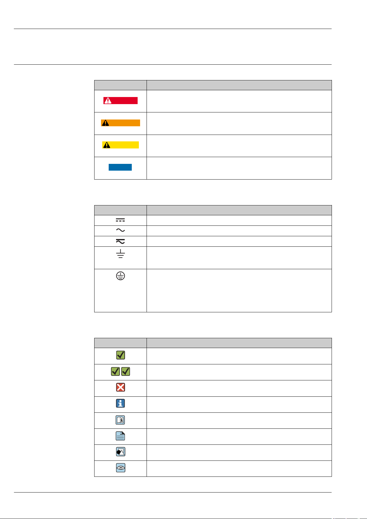
Symbols Safety symbols
Symbol Meaning
Electrical symbols
Micropilot FMR50
DANGER!
This symbol alerts you to a dangerous situation. Failure to avoid this situation will
result in serious or fatal injury.
WARNING!
This symbol alerts you to a dangerous situation. Failure to avoid this situation can
result in serious or fatal injury.
CAUTION!
This symbol alerts you to a dangerous situation. Failure to avoid this situation can
result in minor or medium injury.
NOTE!
This symbol contains information on procedures and other facts which do not result in
personal injury.
Symbol Meaning
Direct current
Alternating current
Direct current and alternating current
Ground connection
A grounded terminal which, as far as the operator is concerned, is grounded via a
grounding system.
Protective Earth (PE)
A terminal which must be connected to ground prior to establishing any other
connections.
The ground terminals are situated inside and outside the device:
• Inner ground terminal: Connects the protectiv earth to the mains supply.
• Outer ground terminal: Connects the device to the plant grounding system.
Symbols for certain types of information
Symbol Meaning
Permitted
Procedures, processes or actions that are permitted.
Preferred
Procedures, processes or actions that are preferred.
Forbidden
Procedures, processes or actions that are forbidden.
Tip
Indicates additional information.
Reference to documentation.
Reference to page.
Reference to graphic.
Visual inspection.
4 Endress+Hauser

Micropilot FMR50
1.
-
.
Symbols in graphics
Symbol Meaning
1, 2, 3 ... Item numbers
, 2., 3.… Series of steps
A, B, C, ... Views
A-A, B-B, C-C, ... Sections
Hazardous area
Indicates a hazardous area.
Safe area (non-hazardous area)
Indicates the non-hazardous area.
Symbols at the device
Symbol Meaning
Safety instructions
Observe the safety instructions contained in the associated Operating Instructions.
Temperature resistance of the connection cables
Specifies the minimum value of the temperature resistance of the connection cables.
Endress+Hauser 5

Micropilot FMR50
Terms and abbreviations
Term/abbreviation Explanation
BA Document type "Operating Instructions"
KA Document type "Brief Operating Instructions"
TI Document type "Technical Information"
SD Document type "Special Documentation"
XA Document type "Safety Instructions"
PN Nominal pressure
MWP Maximum Working Pressure
The MWP can also be found on the nameplate.
ToF Time of Flight
FieldCare Scalable software tool for device configuration and integrated plant asset management
solutions
DeviceCare Universal configuration software for Endress+Hauser HART, PROFIBUS,
FOUNDATION Fieldbus and Ethernet field devices
DTM Device Type Manager
DD Device Description for HART communication protocol
εr (DC value) Relative dielectric constant
Operating tool The term "operating tool" is used in place of the following operating software:
• FieldCare / DeviceCare, for operation via HART communication and PC
• SmartBlue (app), for operation using an Android or iOS smartphone or tablet.
BD Blocking Distance; no signals are analyzed within the BD.
PLC Programmable Logic Controller
CDI Common Data Interface
PFS Pulse Frequence Status (Switching output)
MBP Manchester Bus Powered
PDU Protocol Data Unit
6 Endress+Hauser

Micropilot FMR50
Registered trademarks
®
HART
Registered trademark of the FieldComm Group, Austin, USA
PROFIBUS
®
Registered trademark of the PROFIBUS User Organization, Karlsruhe, Germany
FOUNDATIONTM Fieldbus
Registered trademark of the FieldComm Group, Austin, Texas, USA
Bluetooth®
The Bluetooth® word mark and logos are registered trademarks owned by the Bluetooth SIG, Inc. and
any use of such marks by Endress+Hauser is under license. Other trademarks and trade names are
those of their respective owners.
Apple®
Apple, the Apple logo, iPhone, and iPod touch are trademarks of Apple Inc., registered in the U.S.and
other countries. App Store is a service mark of Apple Inc.
Android®
Android, Google Play and the Google Play logo are trademarks of Google Inc.
KALREZ®, VITON
®
Registered trademark of DuPont Performance Elastomers L.L.C., Wilmington, USA
TEFLON
®
Registered trademark of E.I. DuPont de Nemours & Co., Wilmington, USA
TRI CLAMP
®
Registered trademark of Alfa Laval Inc., Kenosha, USA
Endress+Hauser 7
Function and system design
F
L
D
E
R
0%
100%
Micropilot FMR50
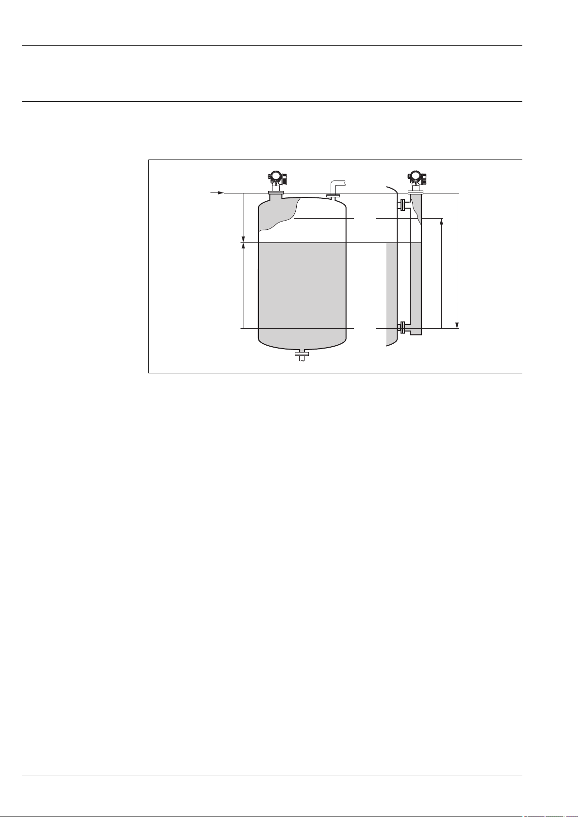
Measuring principle
The Micropilot is a "downward-looking" measuring system, operating based on the time-of-flight
method (ToF). It measures the distance from the reference point (process connection) to the product
surface. Radar impulses are emitted by an antenna, reflected off the product surface and received
again by the radar system.
A0017871
1 Setup parameters of the Micropilot
R Reference point of the measurement (lower edge of the flange or threaded connection)
E Empty calibration ( = zero)
F Full calibration (= span)
D Measured distance
L Level (L = E - D)
Input
The reflected radar impulses are received by the antenna and transmitted into the electronics. A
microprocessor evaluates the signal and identifies the level echo caused by the reflection of the radar
impulse at the product surface. The unambiguous signal identification is accomplished by the
PulseMaster® eXact software together with the Multi-echo tracking algorithms, based on many
years of experience with time-of-flight technology.
The distance D to the product surface is proportional to the time of flight t of the impulse:
D = c · t/2,
with c being the speed of light.
Based on the known empty distance E, the level L is calculated:
L = E – D
The reference point R of the measurement is located at the process connection. For details see the
dimensional drawing:
FMR50: → 54
The Micropilot is equipped with functions to suppress interference echoes. The user can activate
these functions. Together with the multi-echo tracking algorithms they ensure that interference
echoes (i.e. from edges and weld seams) are not interpreted as level echo.
8 Endress+Hauser

Micropilot FMR50
Output
The Micropilot is commissioned by entering an empty distance "E" (=zero), a full distance "F" (=span)
and application parameters which automatically adapt the instrument to the process conditions. For
models with a current output, the factory adjustment for zero point "E" and span "F" is 4 mA and 20
mA. For digital outputs and the display module, the factory adjustment for zero point "E" and span "F"
is 0 % and 100 %.
A linearization with max. 32 points, based on a table entered either manually or semi-automatically,
can be activated locally or remotely. This function provides a measurement in engineering units and
a linear output signal for spheres, horizontal cylindrical tanks and vessels with conical outlet.
Life cycle of the product
Engineering
• Universal measuring principle
• Measurement unaffected by medium properties
• Hardware and software developed according to SIL IEC 61508
Procurement
• Endress+Hauser being the world market leader in level measurement guarantees asset protection
• Worldwide support and service
Installation
• Special tools are not required
• Reverse polarity protection
• Modern, detachable terminals
• Main electronics protected by a separate connection compartment
Commissioning
• Fast, menu-guided commissioning in only a few steps on site or from the control room
• Plain text display in national languages reduces the risk of error or confusion
• Direct local access of all parameters
• Short instruction manual at the device
Operation
• Multi-echo tracking: Reliable measurement through self-learning echo-search algorithms taking
into account the short-term and long-term history in order to check the found echoes for
plausibility and to suppress interference echoes.
• Diagnostics in accordance with NAMUR NE107
Maintenance
• HistoROM: Data backup for instrument settings and measured values
• Exact instrument and process diagnosis to assist fast decisions with clear details concerning
remedies
• Intuitive, menu-guided operating concept in national languages saves costs for training,
maintenance and operation
• Cover of the electronics compartment can be opened in hazardous areas
Retirement
• Order code translation for subsequent models
• RoHS-conforming (Restriction of certain Hazardous Substances), unleaded soldering of electronic
components
• Environmentally sound recycling concept
Endress+Hauser 9
Input
Micropilot FMR50
Measured variable
The measured variable is the distance between the reference point and the product surface.
The level is calculated from this distance, taking into account the empty distance "E" entered by the
user.
If required, the level can be converted into other variables (volume, mass) by means of a linearization
(up to 32 points).
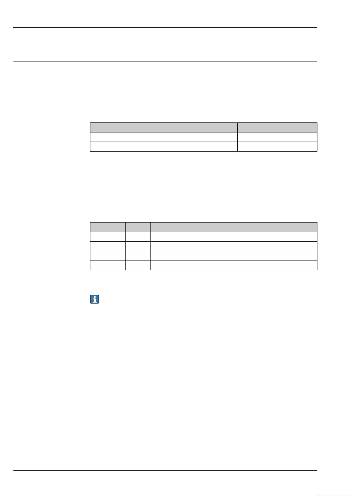
Measuring range Maximum measuring range
Device Maximum measuring range
FMR50 - standard version 30 m (98 ft)
FMR50 - with "Advanced dynamics" application package 40 m (131 ft)
Usable measuring range
The usable measuring range depends on the size of the antenna, the reflectivity of the medium, the
mounting location and eventual interference reflections.
The following tables describe the groups of media as well as the achievable measuring range as a
function of application and media group. If the dielectric constant of a medium is unknown, it is
recommended to assume media group B to ensure a reliable measurement.
Media groups
Media groups DC (εr) Example
A 1.4 to 1.9 non-conducting liquids, e.g. liquefied gas
B 1.9 to 4 non-conducting liquids, e.g. benzene, oil, toluene, …
C 4 to 10 e.g. concentrated acids, organic solvents, esters, aniline, alcohol, acetone, …
D > 10 conducting liquids, e.g. aqueous solutions, dilute acids and alkalis
1)
1) Treat Ammonia NH3 as a medium of group A.
For dielectric constants (DC values) of many media commonly used in various industries refer
to:
• the Endress+Hauser DC manual (CP01076F)
• the Endress+Hauser "DC Values App" (available for Android and iOS)
10 Endress+Hauser
Micropilot FMR50
A B
25
(82)
15
(49)
C D
3
(9.9)
10
(32)
15
(49)
5
(16)
8
(26)
5
(16)
A B C D
8
(26)
15
(49)
20
(65)20(65)
10
(32)
20
(65)
30
(98)30(98)
A B C D
10
(32)
25
(82)
30
(98)30(98)
15
(49)
30
(98)
40
(131)40(131)
B C D
(6.6)
4
(13)
7.5
(24)
10
(32)
(16)
5
2
A B C D
*
2.5
(8)
5
(16)
10
(32)
15
(49)
5
(16)
10
(32)
15
(49)
20
(65)
A B C D
5
(16)
10
(32)
15
(49)
25
(82)
7.5
(24)
15
(49)
25
(82)
35
(110)
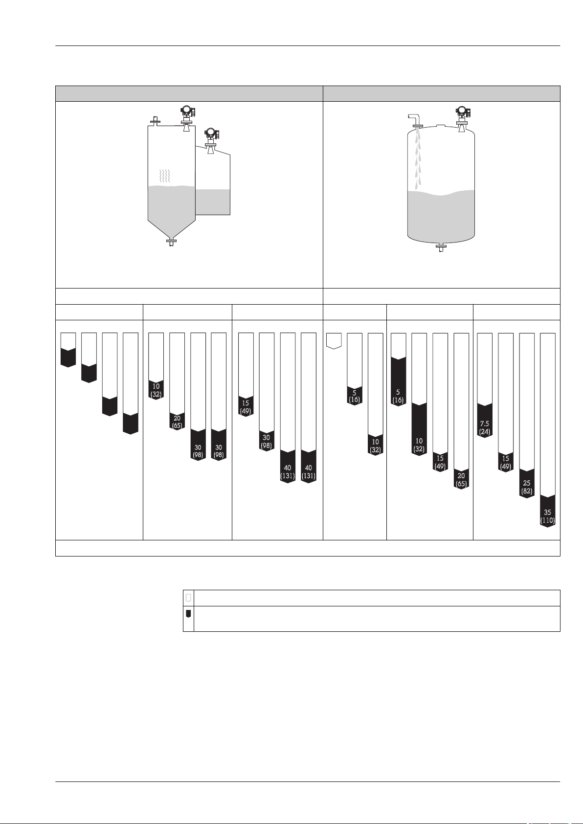
Storage tank Buffer tank
A0018833
Calm product surface (e.g. intermittent filling, filling from bottom, immersion
tubes)
Moving surfaces (e.g. continuous filling, from above, mixing jets)
Antenna size Antenna size
40 mm (1½ in) 80 mm (3 in) 100 mm (4 in) 40 mm (1½ in) 80 mm (3 in) 100 mm (4 in)
A0018858
A0018303
A0018304
A0018863
A0019040
Measuring range [m (ft)]
A0018835
A0018866
Endress+Hauser 11
Legend
Measuring range of the standard version
Measuring range for the "Advanced dynamics" application package (product structure: feature 540:
"Application Package", Option EM: "Advanced dynamics")

Micropilot FMR50
B C D
1
(3.2)
2
(6.6)
3
(9.8)
5
(16)
B C D
2.5
(8.2)
5
(16)
12
(39)
15
(49)
8
(26)
B C D
4
(13)
(16)
5
8
(26)
15
(49)
20
(65)
10
(32)
20
(66)
A, B, C, D
Process tank with agitator Stilling well
A0018837
Turbulent surface (e.g. filling from above, agitators, baffles)
Antenna size Antenna size
40 mm (1½ in) 80 mm (3 in) 100 mm (4 in) 40 ... 100 mm (1½ ... 4 in)
A0018867
A0018869
A0018870
Measuring range [m (ft)]
A0018842
A0018851
Legend
Measuring range of the standard version
Measuring range for the "Advanced dynamics" application package (product structure: feature 540:
"Application Package", Option EM: "Advanced dynamics")
12 Endress+Hauser

Micropilot FMR50
Operating frequency
Transmitting power
K-band (~ 26 GHz)
Up to 8 Micropilot transmitters can be installed in the same tank because the transmitter pulses are
statistically coded.
Distance Average energy density in beam direction
Standard version With "Advanced dynamics" application
1 m (3.3 ft) < 12 nW/cm
5 m (16 ft) < 0.4 nW/cm
2
2
1) Product structure, feature 540: "Application package", option EM: "Advanced dynamics"
1)
package
< 64 nW/cm
< 2.5 nW/cm
2
2
Endress+Hauser 13

Output
Output signal HART
Signal coding FSK ±0.5 mA over current signal
Data transmission rate 1 200 Bit/s
Galvanic isolation Yes
Bluetooth® wireless technology
Device version Ordering feature 610 "Accessory mounted", option NF "Bluetooth"
Operation / configuration By the SmartBlue app.
Range under reference conditions > 10 m (33 ft)
Encryption Encrypted communication and password encryption prevent incorrect
PROFIBUS PA
Micropilot FMR50
operation by unauthorized persons.
Signal coding Manchester Bus Powered (MBP)
Data transmission rate 31.25 kBit/s, voltage mode
Galvanic isolation Yes
FOUNDATION Fieldbus
Signal coding Manchester Bus Powered (MBP)
Data transmission rate 31.25 kBit/s, voltage mode
Galvanic isolation Yes
Switch output
For HART devices, the switch output is available as an option. See product structure, feature 20:
"Power Supply, Output", option B: "2-wire; 4-20mA HART, switch output"
Devices with PROFIBUS PA and FOUNDATION Fieldbus always have a switch output.
14 Endress+Hauser

Micropilot FMR50
Switch output
Function Open collector switching output
Switching behavior Binary (conductive or non-conductive), switches when the programmable switch
point is reached
Failure mode non-conductive
Electrical connection values U = 16 to 35 VDC, I = 0 to 40 mA
Internal resistance RI < 880 Ω
The voltage drop at this internal resistance has to be taken into account on
planning the configuration. For example, the resulting voltage at a connected
relay must be sufficient to switch the relay.
Insulation voltage floating, Insulation voltage 1 350 VDC to power supply aund 500 VAC to ground
Switch point freely programmable, separately for switch-on and switch-off point
Switching delay freely programmable from 0 to 100 s, separately for switch-on and switch-off
point
Number of switching cycles corresponds to the measuring cycle
Signal source
device variables
Number of switching cycles unlimited
• Level linearized
• Distance
• Terminal voltage
• Electronic temperature
• Relative echo amplitude
• Diagnostic values, Advanced diagnostics
Signal on alarm
Depending on the interface, failure information is displayed as follows:
• Current output (for HART devices)
– Failsafe mode selectable (in accordance with NAMUR Recommendation NE 43):
– Failsafe mode with user-selectable value: 3.59 to 22.5 mA
• Local display
– Status signal (in accordance with NAMUR Recommendation NE 107)
– Plain text display
• Operating tool via digital communication (HART, PROFIBUS PA, FOUNDATION Fieldbus) or
service interface (CDI)
– Status signal (in accordance with NAMUR Recommendation NE 107)
– Plain text display
Linearization
The linearization function of the device allows the conversion of the measured value into any unit of
length or volume. Linearization tables for calculating the volume in cylindrical tanks are preprogrammed. Other linearization tables of up to 32 value pairs can be entered manually or semiautomatically.
Galvanic isolation
All circuits for the outputs are galvanically isolated from each other.
Protocol-specific data HART
Manufacturer ID 17 (0x11)
Device type ID 0x1128
HART specification 7.0
Device description files (DTM, DD) Information and files under:
HART load min. 250 Ω
Minimum alarm: 3.6 mA
Maximum alarm (= factory setting): 22 mA
• www.endress.com
• www.fieldcommgroup.org
Endress+Hauser 15

Micropilot FMR50
HART device variables The measured values can be freely assigned to the device variables.
Measured values for PV (primary variable)
• Level linearized
• Distance
• Electronic temperature
• Relative echo amplitude
• Area of incoupling
• Analog output adv. diagnostics 1
• Analog output adv. diagnostics 2
Measured values for SV, TV, FV (second, third and fourth variable)
• Level linearized
• Distance
• Electronic temperature
• Terminal voltage
• Relative echo amplitude
• Absolute echo amplitude
• Area of incoupling
• Analog output adv. diagnostics 1
• Analog output adv. diagnostics 2
Supported functions • Burst mode
• Additional transmitter status
Wireless HART data
Minimum start-up voltage 16 V
Start-up current 3.6 mA
Start-up time 65 s
Minimum operating voltage 14.0 V
Multidrop current 4.0 mA
Set-up time 15 s
PROFIBUS PA
Manufacturer ID 17 (0x11)
Ident number 0x1559
Profile version 3.02
GSD file Information and files under:
GSD file version
Output values Analog Input:
• www.endress.com
• www.profibus.org
• Level linearized
• Distance
• Terminal voltage
• Electronic temperature
• Absolute echo amplitude
• Relative echo amplitude
• Analog output adv. diagnostics 1
• Analog output adv. diagnostics 2
Digital Input:
• Digital output AD 1
• Digital output AD 2
• Switch output
16 Endress+Hauser

Micropilot FMR50
Input values Analog Output:
• Analog value from PLC (for sensor block external pressure to compensate gas phase
effects)
• Analog value from PLC to be indicated on the display
Digital Output:
• Extended diagnostic block
• Level limiter
• Sensor block measurement on
• Sensor block save history on
• Status output
Supported functions • Identification & Maintenance
Einfachste Geräteidentifizierung seitens des Leitsystems und des Typenschildes
• Automatic Ident Number Adoption
GSD compatibility mode with respect to the preceding product Micropilot M FMR2xx
• Physical Layer Diagnostics
Installation check of the PRFIBUS segment and the Micropilot FMR5x via the terminal
voltage and telegram surveillance.
• PROFIBUS Up-/Download
Up to 10 times faster writing and reading of parameters via PROFIBUS up-/download
• Condensed Status
Simple and self-explanatory diagnostic information by categorization of occurring
diagnostic messages.
FOUNDATION Fieldbus
Manufacturer ID 0x452B48
Device type 0x1028
Device Revision 0x01
DD Revision Information and files can be found:
CFF Revision
Device Tester Version (ITK Version) 6.0.1
ITK Test Campaign Number IT085300
Link Master (LAS) capable yes
Link Master / Basic Device selectable yes; default: Basic Device
Node address Default: 247 (0xF7)
Features supported Following methods are supported:
Virtual Communication Relationships (VCRs)
Number of VCRs 44
Number of Link Objects in VFD 50
Permanent entries 1
Client VCRs 0
Server VCRs 10
Source VCRs 43
Sink VCRs 0
Subscriber VCRs 43
Publisher VCRs 43
Device Link Capabilities
Slot time 4
• www.endress.com
• www.fieldcommgroup.org
• Restart
• ENP Restart
• Setup
• Linearization
• Self Check
Endress+Hauser 17

Micropilot FMR50
Min. inter PDU delay 8
Max. response delay 20
Transducer Blocks
Block Content Output values
Setup Transducer Block Contains all parameters for a standard commissioning
procedure
Advanced Setup
Transducer Block
Display Transducer Block Contains all parameters for the configuration of the
Diagnostic Transducer
Block
Advanced Diagnostic
Transducer Block
Expert Configuration
Transducer Block
Expert Information
Transducer Block
Service Sensor Transducer
Block
Service Information
Transducer Block
Data Transfer Transducer
Block
Contains all parameters for a more detailed
configuration of the device
display module
Contains diagnostic information no output values
Contains parameters for the Advanced Diagnostic no output values
Contains parameters which require detailed knowledge
of the functionalities of the device
Contains information about the state of the device no output values
Contains parameters which can only be operated by
Endress+Hauser service personnel
Contains information on the state of device which is
relevant for service operations
Contains parameters which allow to backup the device
configuration in the display module and to restore it
into the device. Access to these parameters is restricted
to the Endress+Hauser service.
• Level or volume
(Channel 1)
• Distance (Channel 2)
no output values
no output values
no output values
no output values
no output values
no output values
1)
1) depending on the configuration of the block
Function Blocks
Block Content Number of
permanent
blocks
Resource Block The Resource Block contains all the
data that uniquely identifies the
field device. It is an electronic
version of a nameplate of the
device.
Analog Input
Block
Discrete Input
Block
Mutiple
Analog Output
Block
Mutiple
Discrete
Output Block
The AI block takes the
manufacturer's input data, selected
by channel number, and makes it
available to other function blocks at
its output.
The DI block takes a discrete input
value (e.g. indication of an level
limit), and makes it available to
other function blocks at its output.
This block is used to transfer analog
data from the bus into the device
This block is used to transfer
discrete data from the bus to the
device.
1 0 - enhanced
2 3 25 ms enhanced
1 2 20 ms standard
1 0 20 ms standard
1 0 20 ms standard
Number of
instantiable
blocks
Execution
time
Functionality
18 Endress+Hauser

Micropilot FMR50
Block Content Number of
permanent
blocks
PID Block The PID block serves as
proportional-integralderivative
controller and is used almost
universally to do closed-loopcontrol in the field including
cascade and feedforward.
Arithmetic
Block
Signal
Characterizer
Block
Input Selector
Block
Integrator
Block
Analog Alarm
Block
This block is designed to permit
simple use of popular measurement
math functions. The user does not
have to know how to write
equations. The math algorithm is
selected by name, chosen by the
user for the function to be done.
The signal characterizer block has
two sections, each with an output
that is a non-linear function of the
respective input. The non-linear
function is determined by a single
look-up table with 21 arbitrary x-y
pairs.
The input selector block provides
selection of up to four inputs and
generates an output based on the
configured action. This block
normally receives its inputs from AI
blocks. The block performs
maximum, minimum, middle,
average and ‘first good’ signal
selection.
The Integrator Function Block
integrates a variable as a function
of the time or accumulates the
counts from a Pulse Input block.
The block may be used as a
totalizer that counts up until reset
or as a batch totalizer that has a
setpoint, where the integrated or
accumulated value is compared to
pre-trip and trip settings,
generating discrete signals when
these settings are reached.
1 1 25 ms standard
1 1 25 ms standard
1 1 25 ms standard
1 1 25 ms standard
1 1 25 ms standard
1 1 25 ms standard
Number of
instantiable
blocks
Execution
time
Functionality
Up to 20 blocks can be instantiated in the device altogether, including the blocks already
instantiated on delivery.
Endress+Hauser 19

Terminal assignment
1
+
2
-
A
1
+
2
-
B
1
2
3
5
4
1
2
3
++
--
Y
I
6
1
2
Micropilot FMR50
Power supply
Terminal assignment 2-wire: 4-20 mA HART
2 Terminal assignment 2-wire: 4-20 mA HART
A Without integrated overvoltage protection
B With integrated overvoltage protection
1 Connection 4-20 mA HART passive: terminals 1 and 2, without integrated overvoltage protection
2 Connection 4-20 mA HART passive: terminals 1 and 2, with integrated overvoltage protection
3 Terminal for cable screen
Block diagram 2-wire: 4-20 mA HART
3 Block diagram 2-wire: 4-20 mA HART
1 Active barrier with power supply (e.g. RN221N); observe terminal voltage
2 HART communication resistor (≥ 250 Ω); observe maximum load
3 Connection for Commubox FXA195 or FieldXpert SFX350/SFX370 (via VIATOR Bluetooth modem)
4 Analog display device; observe maximum load
5 Cable screen; observe cable specification
6 Measuring device
A0036498
A0036499
20 Endress+Hauser

Micropilot FMR50
1
3
+
+
2
4
-
-
A
1
3
+
+
2
4
-
-
B
1
4
5
2
3
5
4
1
2
3
+
+
+
-
-
-
Y
I
6
7
1
2
3
4
Terminal assignment 2-wire: 4-20 mA HART, switch output
4 Terminal assignment 2-wire: 4-20 mA HART, switch output
A Without integrated overvoltage protection
B With integrated overvoltage protection
1 Connection 4-20 mA HART passive: terminals 1 and 2, without integrated overvoltage protection
2 Connection switch output (Open Collector): terminals 3 and 4, without integrated overvoltage protection
3 Connection switch output (Open Collector): terminals 3 and 4, with integrated overvoltage protection
4 Connection 4-20 mA HART passive: terminals 1 and 2, with integrated overvoltage protection
5 Terminal for cable screen
Block diagram 2-wire: 4-20 mA HART, switch output
5 Block diagram 2-wire: 4-20 mA HART, switch output
1 Active barrier with power supply (e.g. RN221N); observe terminal voltage
2 HART communication resistor (≥ 250 Ω); observe maximum load
3 Connection for Commubox FXA195 or FieldXpert SFX350/SFX370 (via VIATOR Bluetooth modem)
4 Analog display device; observe maximum load
5 Cable screen; observe cable specification
6 Measuring device
7 Switch output (Open Collector)
A0036500
A0036501
Endress+Hauser 21

Terminal assignment 2-wire: 4-20 mA HART, 4-20 mA
1
3
+
+
2
4
-
-
A
1
3
+
+
2
4
-
-
B
1
4
5
2
3
5
4
1
2
3
+
+
+
+
-
-
-
-
Y
I
6
7
8
1
2
3
4
Micropilot FMR50
A0036500
6 Terminal assignment 2-wire: 4-20 mA HART, 4-20 mA
A Without integrated overvoltage protection
B With integrated overvoltage protection
1 Connection current output 1, 4-20 mA HART passive: terminals 1 and 2, without integrated overvoltage
protection
2 Connection current output 2, 4-20 mA: terminals 3 and 4, without integrated overvoltage protection
3 Connection current output 2, 4-20 mA: terminals 3 and 4, with integrated overvoltage protection
4 Connection current output 1, 4-20 mA HART passive: terminals 1 and 2, with integrated overvoltage
protection
5 Terminal for cable screen
Block diagram 2-wire: 4-20 mA HART, 4-20 mA
A0036502
7 Block diagram 2-wire: 4-20 mA HART, 4-20 mA
1 Active barrier with power supply (e.g. RN221N); observe terminal voltage
2 HART communication resistor (≥ 250 Ω); observe maximum load
3 Connection for Commubox FXA195 or FieldXpert SFX350/SFX370 (via VIATOR Bluetooth modem)
4 Analog display device; observe maximum load
5 Cable screen; observe cable specification
6 Measuring device
7 Analog display device; observe maximum load
8 Active barrier with power supply (e.g. RN221N), current output 2; observe terminal voltage
22 Endress+Hauser

Micropilot FMR50
3
1
+
L+
4
2
-
L-
1
3
2
5
4
+
L+
-
L-
Y
I
6
7
3
4
1
2
Terminal assignment 4-wire: 4-20 mA HART (10.4 to 48 VDC)
8 Terminal assignment 4-wire: 4-20 mA HART (10.4 to 48 VDC)
1 Connection 4-20 mA HART (active): terminals 3 and 4
2 Connection supply voltage: terminals 1 and 2
3 Terminal for cable screen
Block diagram 4-wire: 4-20 mA HART (10.4 to 48 VDC)
9 Block diagram 4-wire: 4-20 mA HART (10.4 to 48 VDC)
1 Evaluation unit, e.g. PLC
2 HART communication resistor (≥ 250 Ω); observe maximum load
3 Connection for Commubox FXA195 or FieldXpert SFX350/SFX370 (via VIATOR Bluetooth modem)
4 Analog display device; observe maximum load
5 Cable screen; observe cable specification
6 Measuring device
7 Supply voltage; observe terminal voltage, observe cable specification
A0036516
A0036526
Endress+Hauser 23

Terminal assignment 4-wire: 4-20 mA HART (90 to 253 VAC)
3
1
+
L
4
2
-
N
3
2
Micropilot FMR50
10 Terminal assignment 4-wire: 4-20 mA HART (90 to 253 VAC)
1 Connection 4-20 mA HART (active): terminals 3 and 4
2 Connection supply voltage: terminals 1 and 2
3 Terminal for cable screen
CAUTION
L
To ensure electrical safety:
Do not disconnect the protective connection.
‣
Disconnect the supply voltage before disconnecting the protective earth.
‣
Connect protective earth to the internal ground terminal (3) before connecting the supply
voltage. If necessary, connect the potential matching line to the external ground terminal.
In order to ensure electromagnetic compatibility (EMC): Do not only ground the device via the
protective earth conductor of the supply cable. Instead, the functional grounding must also be
connected to the process connection (flange or threaded connection) or to the external ground
terminal.
An easily accessible power switch must be installed in the proximity of the device. The power
switch must be marked as a disconnector for the device (IEC/EN61010).
A0036519
24 Endress+Hauser

Micropilot FMR50
5
4
+
L
-
N
Y
I
6
7
3
4
1
2
1
3
+
+
2
4
-
-
A
1
3
+
+
2
4
-
-
B
4
5
2
3
Block diagram 4-wire: 4-20 mA HART (90 to 253 VAC)
A0036527
11 Block diagram 4-wire: 4-20 mA HART (90 to 253 VAC)
1 Evaluation unit, e.g. PLC
2 HART communication resistor (≥ 250 Ω); observe maximum load
3 Connection for Commubox FXA195 or FieldXpert SFX350/SFX370 (via VIATOR Bluetooth modem)
4 Analog display device; observe maximum load
5 Cable scree; observe cable specification
6 Measuring device
7 Supply voltage; observe terminal voltage, observe cable specification
Terminal assignment PROFIBUS PA / FOUNDATION Fieldbus
A0036500
12 Terminal assignment PROFIBUS PA / FOUNDATION Fieldbus
A Without integrated overvoltage protection
B With integrated overvoltage protection
1 Connection PROFIBUS PA / FOUNDATION Fieldbus: terminals 1 and 2, without integrated overvoltage
protection
2 Connection switch output (Open Collector): terminals 3 and 4, without integrated overvoltage protection
3 Connection switch output (Open Collector): terminals 3 and 4, with integrated overvoltage protection
4 Connection PROFIBUS PA / FOUNDATION Fieldbus: terminals 1 and 2, with integrated overvoltage protection
5 Terminal for cable screen
Endress+Hauser 25

Block diagram PROFIBUS PA / FOUNDATION Fieldbus
+
+
-
-
Y
I
2
3
1
2
3
4
4
13 Block diagram PROFIBUS PA / FOUNDATION Fieldbus
1 Cable screen; observe cable specifications
2 Connection PROFIBUS PA / FOUNDATION Fieldbus
3 Measuring device
4 Switch output (open collector)
Micropilot FMR50
A0036530
26 Endress+Hauser

Micropilot FMR50
3+
+
-
4-
R
i
3+
2
1
+
4-
R
i
Connection examples for the switch output
For HART devices, the switch output is available as an option. See product structure, feature 20:
"Power Supply, Output", option B: "2-wire; 4-20 mA HART, switch output"
Devices with PROFIBUS PA and FOUNDATION Fieldbus always have a switch output.
A0015909
14 Connection of a relay
Suitable relays (examples):
• Solid-state relay: Phoenix Contact OV-24DC/480AC/5 with mounting
rail connector UMK-1 OM-R/AMS
• Electromechanical relay: Phoenix Contact PLC-RSC-12DC/21
15 Connection of a digital input
1 Pull-up resistor
2 Digital input
For optimum interference immunity we recommend to connect an external resistor (internal
resistance of the relay or Pull-up resistor) of < 1 000 Ω.
A0015910
Endress+Hauser 27
Micropilot FMR50
2
1
3
4
4
2
3
1
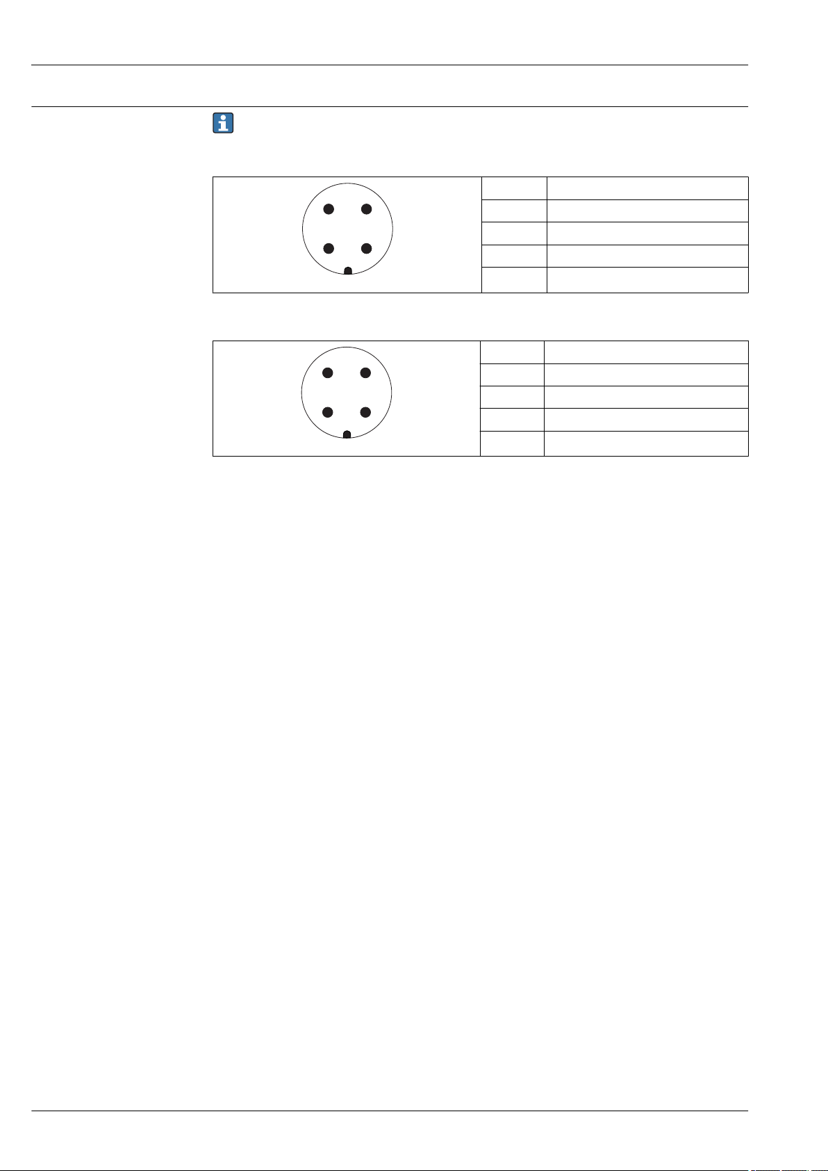
Device plug connectors
For the versions with fieldbus plug connector (M12 or 7/8"), the signal line can be connected
without opening the housing.
Pin assignment of the M12 plug connector
Pin Meaning
1 Signal +
2 not connected
3 Signal -
4 Ground
A0011175
Pin assignment of the 7/8" plug connector
Pin Meaning
1 Signal -
2 Signal +
3 Not connected
4 Screen
A0011176
28 Endress+Hauser

Micropilot FMR50
R [ ]?
U0[V]
10
10.4 21.4
20 30 35
0
500
U0[V]
10
13 24
20 30 35
0
500
R [ ]Ω
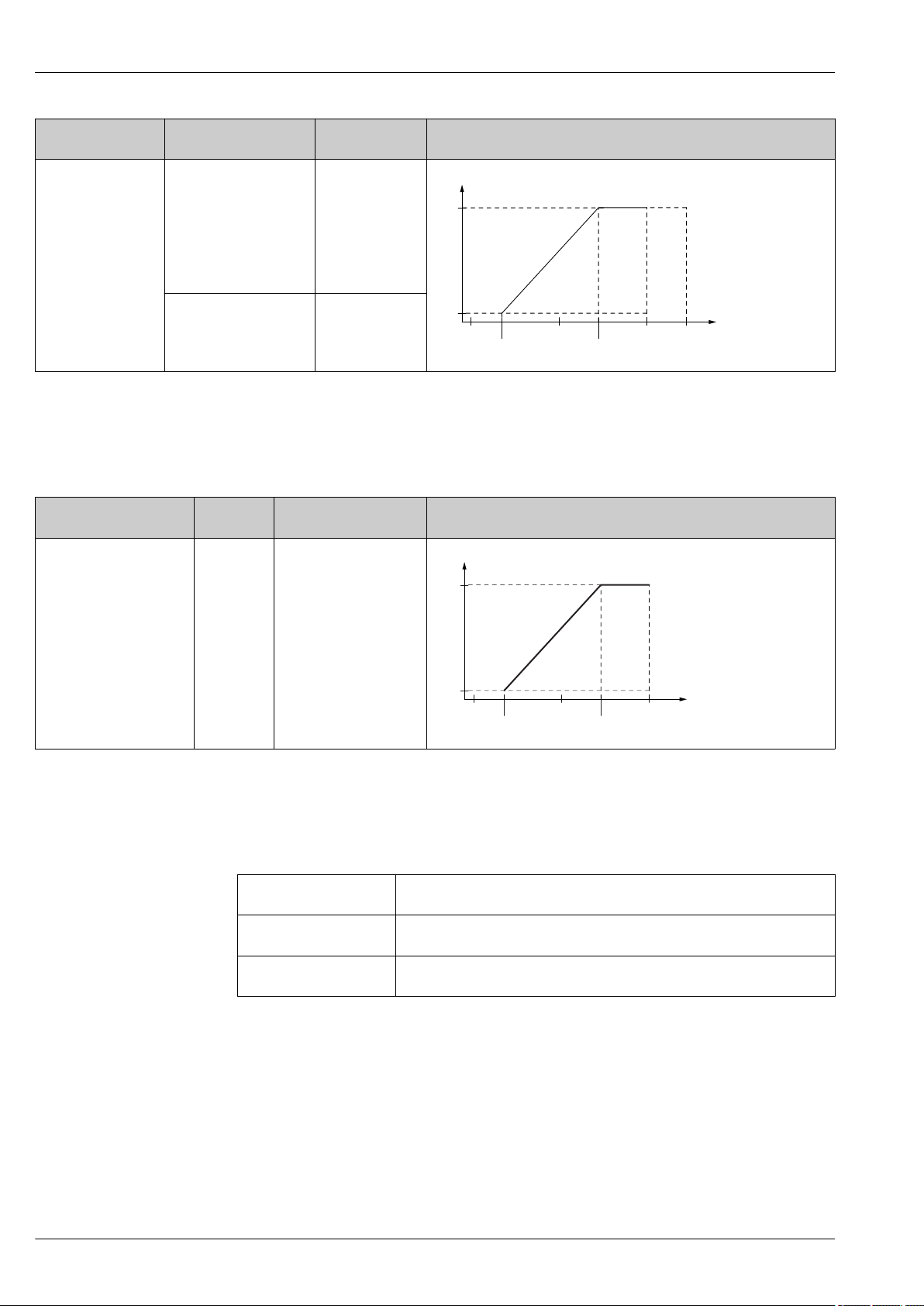
Supply voltage
"Power Supply,
1)
Output"
A: 2-wire; 4-20mA
HART
An external power supply is required.
Various supply units can be ordered from Endress+Hauser: see "Accessories" section→ 94
2-wire, 4-20mA HART, passive
"Approval"
• Non-Ex
• Ex nA
• Ex ic
• CSA GP
Ex ia / IS 10.4 to 30 V
• Ex d(ia) / XP
• Ex ic(ia)
• Ex nA(ia)
• Ex ta / DIP
Ex ia + Ex d(ia) / IS + XP 13 to 30 V
2)
Terminal voltage U at
the device
10.4 to 35 V
13 to 35 V
Maximum load R, depending on the supply voltage U0 at the supply unit
3) 4) 5)
3) 4) 5)
A0017140
5) 6)
5) 6)
A0034771
1) Feature 020 of the product structure
2) Feature 010 of the product structure
3) For ambient temperatures Ta≤ -20 °C (-4 °F) a minimum voltage of 15 V is required for the sartup of the device at the minimum error current (3,6
mA). The startup current can be parametrized. If the device is operated with a fixed current I ≥ 5,5 mA (HART multidrop mode), a voltage of U ≥
10,4 V is sufficient throughout the entire range of ambient temperatures.
4) In the current simulation mode a voltage U ≥ 12.5 V is required.
5) If the Bluetooth modem is used, the minimum supply voltage increases by 3 V.
6) For ambient temperatures Ta≤ -20 °C (-4 °F) a minimum voltage of 16 V is required for the startup of the device at the minimum error current
(3.6 mA).
Endress+Hauser 29
Micropilot FMR50
U0[V]
10
13 24
20 30 35
0
500
R [ ]Ω
R [ ]W
U0[V]
10
13 24
20 28
0
500
"Power Supply,
1)
Output"
B: 2-wire; 4-20 mA
HART, switch output
"Approval"
• Non-Ex
• Ex nA
2)
Terminal voltage
Maximum load R, depending on the supply voltage U0 at the supply unit
U at the device
13 to 35 V
3) 4)
• Ex nA(ia)
• Ex ic
• Ex ic(ia)
• Ex d(ia) / XP
• Ex ta / DIP
• CSA GP
• Ex ia / IS
13 to 30 V
3) 4)
• Ex ia + Ex d(ia) / IS + XP
A0034771
1) Feature 020 of the product structure
2) Feature 010 of the product structure
3) For ambient temperatures Ta≤ -30 °C (-22 °F) a minimum voltage of 16 V is required for the startup of the device at the minimum error current
(3.6 mA).
4) If the Bluetooth modem is used, the minimum supply voltage increases by 3 V.
"Power Supply, Output"
1)
"Approval"
2)
Terminal voltage U at the
Maximum load R, depending on the supply voltage U0 at the supply unit
device
C: 2-wire; 4-20mA HART,
any 13 to 28 V
3) 4)
4-20mA
1) Feature 020 of the product structure
2) Feature 010 of the product structure
3) For ambient temperatures Ta≤ -30 °C (-22 °F) a minimum voltage of 16 V is required for the startup of the device at the minimum error current
(3.6 mA).
4) If the Bluetooth modem is used, the minimum supply voltage increases by 3 V.
Polarity reversal
Yes
protection
Admissible residual ripple
USS < 1 V
at f = 0 to 100 Hz
Admissible residual ripple
USS < 10 mV
at f = 100 to 10000 Hz
A0034841
30 Endress+Hauser
 Loading...