

Page 1
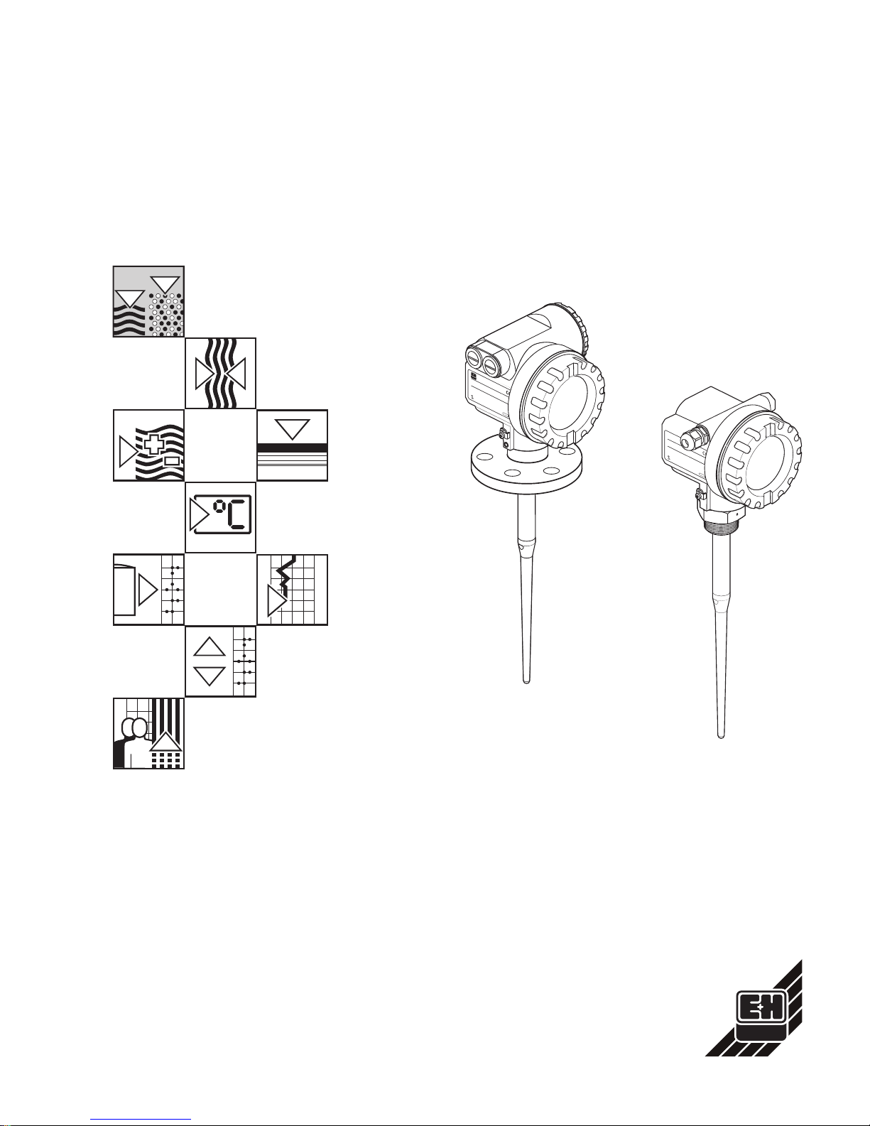
micropilot
FMR 231
Microwave
Level Measurement
Operating Instructions
ENDRESS+HA
USER
MICROPILOTII
IP65
O
rder
Code:
S
er
.-N
o
.:
M
essbereic
h
M
easuring
range
U16.
..36VD
C
4...20m
A
m
ax.
20m
MadeinGermany Maulburg
T>70°C
:
A
t >
8
5
°C
ENDRESS+HA
USER
MICROPILOTII
IP65
O
rder
C
ode:
Ser
.-N
o
.:
M
essbereic
h
M
easuring
range
U16.
..36VD
C
4...20m
A
m
ax.
20m
MadeinGermany Maulburg
T>70°C
:
A
t >
8
5
°C
BA 171F/00/en/06.01
Software version 2.0
017479-1000
Hauser
+
Endress
The Power of Know How
Page 2
Short Instructions
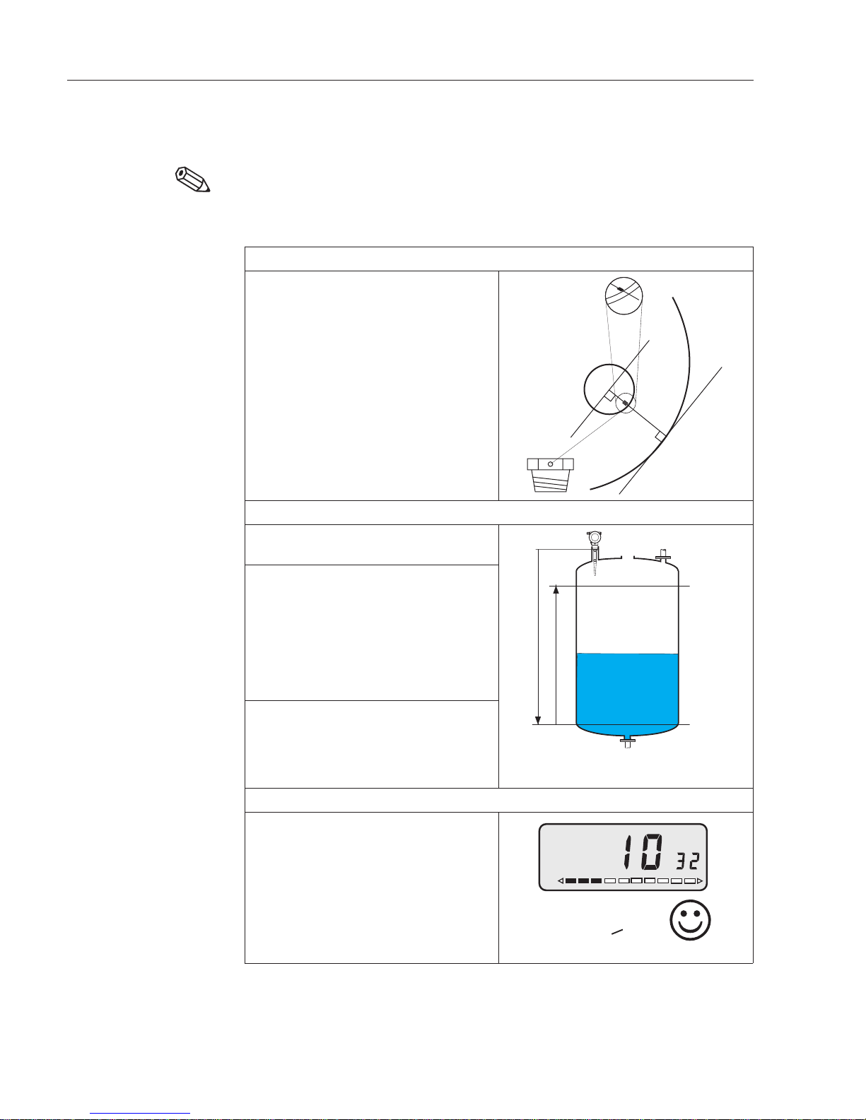
Note!
• The datum point for the empty distance "E" is always the lower face of the process
connection.
• The full distance "F" can extend up to the tip of antenna.
• For stilling wells see Chapter 6.2
Calibration with VU 330
or remote operation for
buffer and storage tanks
Note!
➀ Check installation
1. Check that the alignment mark points
to the tank wall, see also Chapter 2.1.
➁ Calibration
1. Reset
V9H5 = 333
2. Empty and full calibration
V0H1 = E
V0H2 = F
V0H3 = A (application parameter)
A = 0: Tanks up to 7 m
A = 1: Tanks up to 1.5 m
A = 2: Tanks up to 7 m, ε
r
<10
A = 3: Tanks from 7 m to 20 m
3. False echo suppression
Tank empty (≤E)!
V3H0 = 4
V3H1 = (E – 0,8 m)
For partially full tanks see Chapter 6.1.
➂ Check echo quality
1. Echo qualitity
Observe when filling tank
V3H2 ≥ 10 dB
Measurement in order
V3H2 < 10
Measurement not in order:
Optimise alignment, see Chapter 7.5.
Try different nozzle position,
see Chapter 2.1.
flange
tank wall
alignment
mark points
to tank wall
nozzlemin.
30 cm from
wall
thread
F
E
100%
20mA
0%
4mA
V H
V3H2 >10:
Short Instructions Micropilot FMR 231
Endress+Hauser
Page 3

TableofContents
NotesonSafety........... 3
1 Introduction ............ 5
1.1 Measurement principle...... 6
1.2 Measuringsystem........ 8
2 Installation............. 9
2.1 Mountingina tank........ 9
2.2 Mountinginstillingwells...... 12
2.3 Protectivecover......... 13
3 Connection............. 14
3.1 Wiringexamples......... 15
4 Operation ............. 16
4.1 On-site operation ........ 16
4.2 Remoteoperation........ 18
5 On-sitecalibrationwithoutdisplay
VU330...............21
6 CalibrationwithDisplay/Remote
Operation ............. 23
6.1 Basic calibration for tanks..... 24
6.2 Basic calibration for bypasspipes
and stillingwells: ........ 26
6.3 Linearisation.......... 28
6.4 Analogueoutput......... 31
6.5 Safetyfunctions......... 32
6.6 Locking/unlocking the matrix.... 33
6.7 Measuringpointinformation.... 34
7 Trouble-Shooting ..........35
7.1 Self-monitoring .........35
7.2 Error messages.........36
7.3 Faultanalysis..........37
7.4 Applicationparameter ......39
7.5 Echo quality ..........40
7.6 Falseechosuppression......41
7.7 Windowsuppression.......42
7.8 Plausibility...........42
7.9 Simulation ...........43
7.10Reset.............44
8 Maintenance andRepair .......45
8.1 Maintenance ..........45
8.2 Repairs ............45
8.3 Spare parts...........46
9 Technical Data ...........49
9.1 Dimensions...........52
9.2 Deratingdiagrams........53
9.3 Productstructure FMR231E....54
9.4 Productstructure FMR231A....55
10 OperatingMatrix ..........56
10.1Matrixoperation.........56
10.2HART.............57
Index ...............58
Micropilot FMR231 Table of Contents
Endress+Hauser 1
Page 4

Software History
Software
version
Manual
version
Device/
Software
No.
Software revision Changes in manual
1.0 02.98 2310 Original software operable with
Commuwin II, from software version
1.41
HART handheld from software
version 1.11 with DD version 1.0
2.0 11.98 2320 Improvement of evaluation
algorithms
Introduction of matrix field V8H6,
plausibility
Operable via Commuwin II,
software version 2.0
HART handheld from software
version 1.11 with DD version 1.0
No effect on operation
Plausibility described in Chapter 7.8
No visible effects on operation
Bypass pipe application removed,
Chapters 2 and 6 revised
An up/download of device data between devices with different software versions is not possible without special
software tools.
Micropilot FMR 231 Software History
2 Endress+Hauser
Page 5

Notes on Safety
Approved usageThe Micropilot FMR 231 is a compact level transmitter designed for continuous,
non-contact level measurement of liquids, pastes and slurries.
The operating frequency of 5.8 GHz lies in a frequency band approved for industrial use.
FCC approved devices operate at 6.3 GHz. Its low pulse power of 1 mW (1 µW ERP)
allows safe installation in metallic and non-metallic vessels, with no risk to humans or the
environment.
Installation,
commissioning,
operation
The Micropilot FMR 231 has been designed to operate safely in accordance with current
technical, safety and EU standards. If installed incorrectly or used for applications for
which it is not intended, however, itis possible that application-related dangers mayarise,
e.g. product overflow due to incorrect installation or calibration. For this reason, the
instrument must be installed, connected, operated and maintained according to the
instructions in this manual: personnel must be authorised and suitably qualified. The
manual must have been read and understood, and the instructions followed.
Modifications and repairs to the device are permissible only when they are expressly
approved in the manual.
Explosion hazardous
areas
If the device is to be installed in an explosion hazardous area, then the specifications in
the certificate as well as all national and local regulations must be observed. The
instrument can be delivered with the certificates listed in the table below. The certificate
can be identified from the first letter of the order code stamped on the nameplate.
•
Ensure that all personnel are suitably qualified
•
Observe the specifications in the certificate as well as national and local
regulations.
•
Switch off the power before opening the T12 housing in explosion hazardous
areas. The display module is stowed in a separate housing (EEx ia) which can be
opened when the Micropilot is in operation.
FCC approvalThis device complies with part 15 of the FCC rules. Operation is subject to the following
two conditions: (1) This device may not cause harmful interference and (2) this device
must accept any interference received including interference that may cause undesired
operation. In addition, the device may be used in metal vessels only.
Changes or modifications not expressly approved by the party responsible for
compliance could void the user's authority to operate the equipment.
Code Certificate Protection Housing
A none none F12
1 PTB ATEX II 1/2 G EEx ia IIC T3...T6 F12
2 PTB ATEX II 1/2 G EEx e m [ia] T3...T6 T12
K TIIS Ex ia IIC T3 F12
R none none F12 (FCC approval)
S FM IS Cl. I, Div. 1, Group A-D F12 (FCC approval)
T FM XP Cl. I, Div. 1, Group A-D T12 (FCC approval)
U CSA IS Cl. I, Div. 1, Group A-D F12
V CSA XP Cl. I, Div. 1, Group A-D T12
Table S.1
Certificates for use in explosion
hazardous areas
FCC approved devices operate
at 6.3 GHz and are for USA only
ENDRESS+HAUSER
MICROPILOT FMR 231
Order No.FMR 231-
Micropilot FMR 231 Notes on Safety
Endress+Hauser 3
Page 6
Safety Conventions and Symbols
In order to highlight safety-relevant or alternative operating procedures in the manual,
the following conventions have been used, each indicated by a corresponding icon in
the margin.
Safety conventions
Explosion protection
Electrical symbols
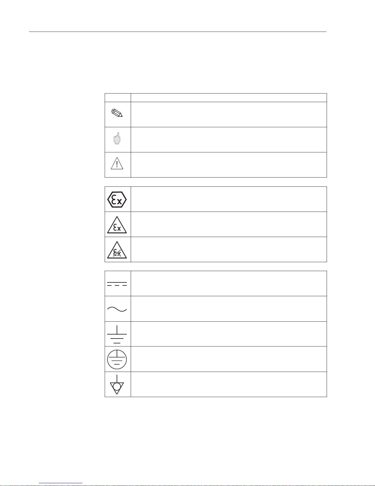
Symbol Meaning
Note!
A note highlights actions or procedures which, if not performed correctly, may indirectly affect
operation or may lead to an instrument response which is not planned
Caution!
Caution highlights actions or procedures which, if not performed correctly, may lead to
personal injury or incorrect functioning of the instrument
Warning!
A warning highlights actions or procedures which, if not performed correctly, will lead to
personal injury, a safety hazard or destruction of the instrument
Device certified for use in explosion hazardous area
If the device has this symbol embossed on its name plate it can be installed in an explosion
hazardous area in accordance with the specifications in the certificate or in a safe area
Explosion hazardous area
Symbol used in drawings to indicate explosion hazardous areas.
Devices located in and wiring entering areas with the designation “explosion hazardous
areas” must conform with the stated type of protection
Safe area (non-explosion hazardous area)
Symbol used in drawings to indicate, if necessary, non-explosion hazardous areas.
Devices located in safe areas stiill require a certificate if their outputs run into explosion
hazardous areas.
Direct voltage
A terminal to which or from which a direct current or voltage may be applied or supplied
Alternating voltage
A terminal to which or from which an alternating (sine-wave) current or voltage may be
applied or supplied
Grounded terminal
A grounded terminal, which as far as the operator is concerned, is already grounded by
means of an earth grounding system
Protective grounding (earth) terminal
A terminal which must be connected to earth ground prior to making any other connection to
the equipment
Equipotential connection (earth bonding)
A connection made to the plant grounding system which may be of type e.g. neutral star or
equipotential line according to national or company practice
Note!
Caution!
Warning!
Notes on Safety Micropilot FMR 231
4 Endress+Hauser
Page 7

1 Introduction
ApplicationThe Micropilot FMR 231 is a loop-powered transmitter. It is used to for continuous
non-contact level measurement of liquids, pastes and sludges. It is suitable for use in:
•
storage tanks, buffer tanks and stilling wells
with few internal fittings and where the product surface is generally calm. Changes of
product, temperature gradients, inert gas blankets or vapours do not influence the
measurement.
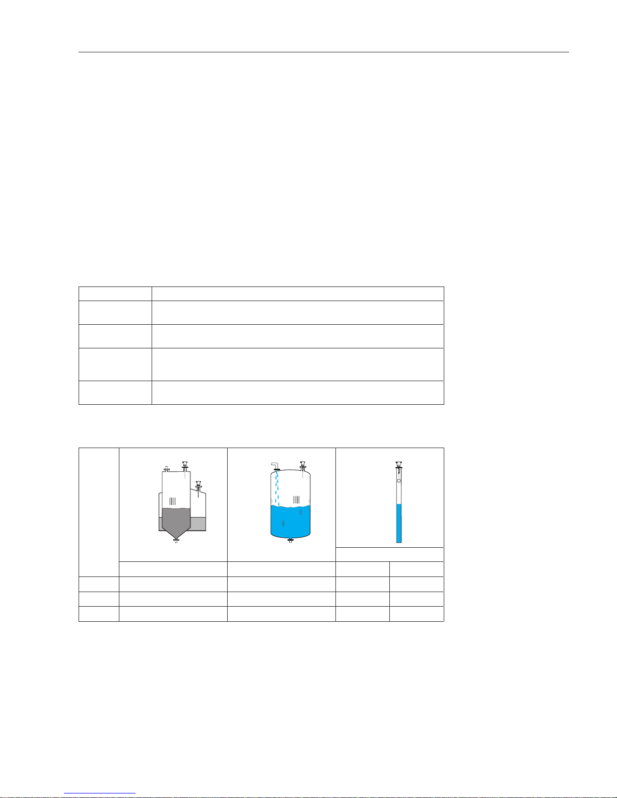
VersionsThe various Micropilot FMR 231 versions result from the combinations between antenna
type, inactive length and the process connection. Table 1.1 summarises them. The
product structure is described in Chapter 9.
BA171Y05
➀
➁
BA171Y06
Fig.1.1
➀
Storage tank
➁
Stilling well or bypass pipe
Application
Standard, for tanks and stilling wells Hygienic, corrosive-resistant, for tanks
and stilling wells
Housing
Housing F12 (standard/EEx ia/Ex IS) or housing T12 (standard/EEx e/Ex XP)
Antenna type
PPS antenna PTFE antenna
Inactive length
100 mm/250 mm
Process connection
Thread 1½ BSPT (R 1½) or 1½ NPT, PVDF
Flange DN50/80/100150/ or ANSI/JIS equivalent
Sanitary coupling: dairy, Tri-clamp or aseptic
Cladding
uncladded cladded or uncladded
Pressure/
flange temperature
0...16 bar
–20°C...+120°C
0...16 bar with cladded flange
0...40 bar uncladded flange
–40°C...+150°C
Wetted parts
PPS, Viton O-ring,
1.4435 flange/thread
Uncladded: PTFE und 1.4435
flange/thread
Cladded: PTFE only
PPS = Polyphenylene sulphide
Table 1.1
Micropilot FMR 231 versions
Micropilot FMR 231 Chapter 1 Introduction
Endress+Hauser 5
Page 8
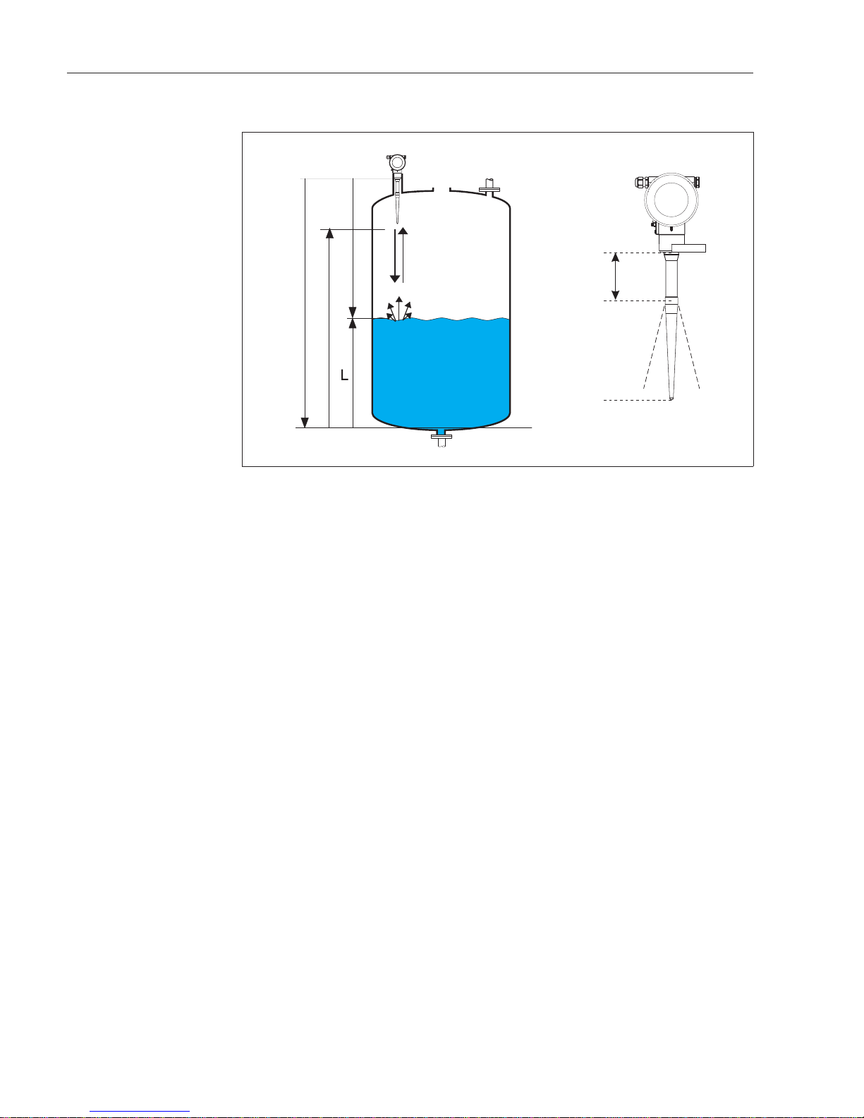
1.1 Measurement principle
Micropilot is a "downward looking" time-of-flight system which measures the distance
from the probe mounting (top of the tank) to the surface of the process medium.
Short microwave pulses are beamed by the antenna towards the product, reflected by
its surface and detected by the same arrangement.
An inactive length at the start of the rod antenna delays the launch of the pulse for a
distance of 100 mm or 250 mm, ensuring that condensation or build-up in the mounting
nozzle does not affect the measurement.
Input The reflected microwaves are detected by the antenna and passed on to the electronics.
Here a microprocessor evaluates the signal and identifies the echo produced by the
reflection of the beam at the product surface. The algorithms used for signal processing
are based on many years of experience in time-of-flight measurement.
The distance D to the product surface isproportional to the time-of-flight of the microwave
pulse t:
D = c • t/2
where c is the speed of propagation
Since the empty distance E is known to the system, it is a simple matter to calculate the
level L:
L = E – D
The datum point for "E" is the bottom face of the process connection.
Micropilot has an echo suppression function which can be activated by the user. This
prevents interference echoes, e.g. caused by fittings within the beam, from being
interpreted as the level echo.
Output Micropilot is calibrated by entering the empty distance E, the full distance F and an
application parameter, which automatically tunes the instrument to the measuring
conditions.
For versions with current output, the points "E" and "F" correspond to 4 mA and 20 mA,
for digital outputs and the display to 0% and 100% level.
F
E
D
BA171Y06
datum point
beam
launched
here
inactive
length
datum point
max.level
Fig.1.2
Microwave measurement
principle
Chapter 1 Introduction Micropilot FMR 231
6 Endress+Hauser
Page 9
A linearisation function, based on a manually or semi-automatically entered table, can
be activated locally at the display unit or via the foreign system interface. This allows
measurement in customer units andprovides a linear outputcurrent for spherical vessels,
horizontal cylinders and tanks with conical outlet.
AccuracyThe accuracy of Micropilot FMR 231 is dependent upon the set measuring range and
material being measured, see Technical Data. Under reference conditions it is capable
of measuring to an accuracy of ±15 mm up to a measuring range of 10 m and ±0.15%
of the range end-value of measuring ranges from 10 m to 20 m..
Measuring rangeThe measuring range depends upon the conditions in the tank and the product to be
measured. Table 1.2 describes the product classes, Table 1.3 the measuring range as
a function of the application and measuring conditions.
In order to ensure the highest accuracy for Class B, we recommend that
•
the empty distance "E" should be 30 cm above the tank bottom.
Class A products can be measured in bypass pipes using the FMR 230V horn antenna,
see operating manual BA 197F.
Product class Examples
A Non-conducting liquids, e.g. propane, buthane etc.
Dielectric constant ε
r.
1.4...1.9
B Non-conducting liquids, e.g. petrochemicals, benzine, oil, toluol, etc.
Dielectric constant ε
r
approx. 1,9...4
C E.g. concentrated acids, organic solvents, analine, esters, alcohols, acetone, etc.
oil/water mixtures
Dielectric constant ε
r
approx. 4...10
D Conducting liquids, watery solutions, dilutte acids and alkalis,
Dielectric constant ε
r
> 10 or electrical conductivity σ>10mS/cm
Table 1.2
Selection of product class
Product
Class
Strorage tank Buffer tank Stilling well or bypass pipe
Measuring range
Measuring range Measuring range
DN 50 DN 80
B
10 m 33 ft 5 m 16 ft 10 m 33 ft 20 m 67 ft
C
15 m 50 ft 8 m 25 ft 10 m 33 ft 20 m 67 ft
D
20 m 67 ft 10 m 33 ft 10 m 33 ft 20 m 67 ft
Table 1.3
Measuring range as a function of
application
Micropilot FMR 231 Chapter 1 Introduction
Endress+Hauser 7
Page 10
1.2 Measuring system
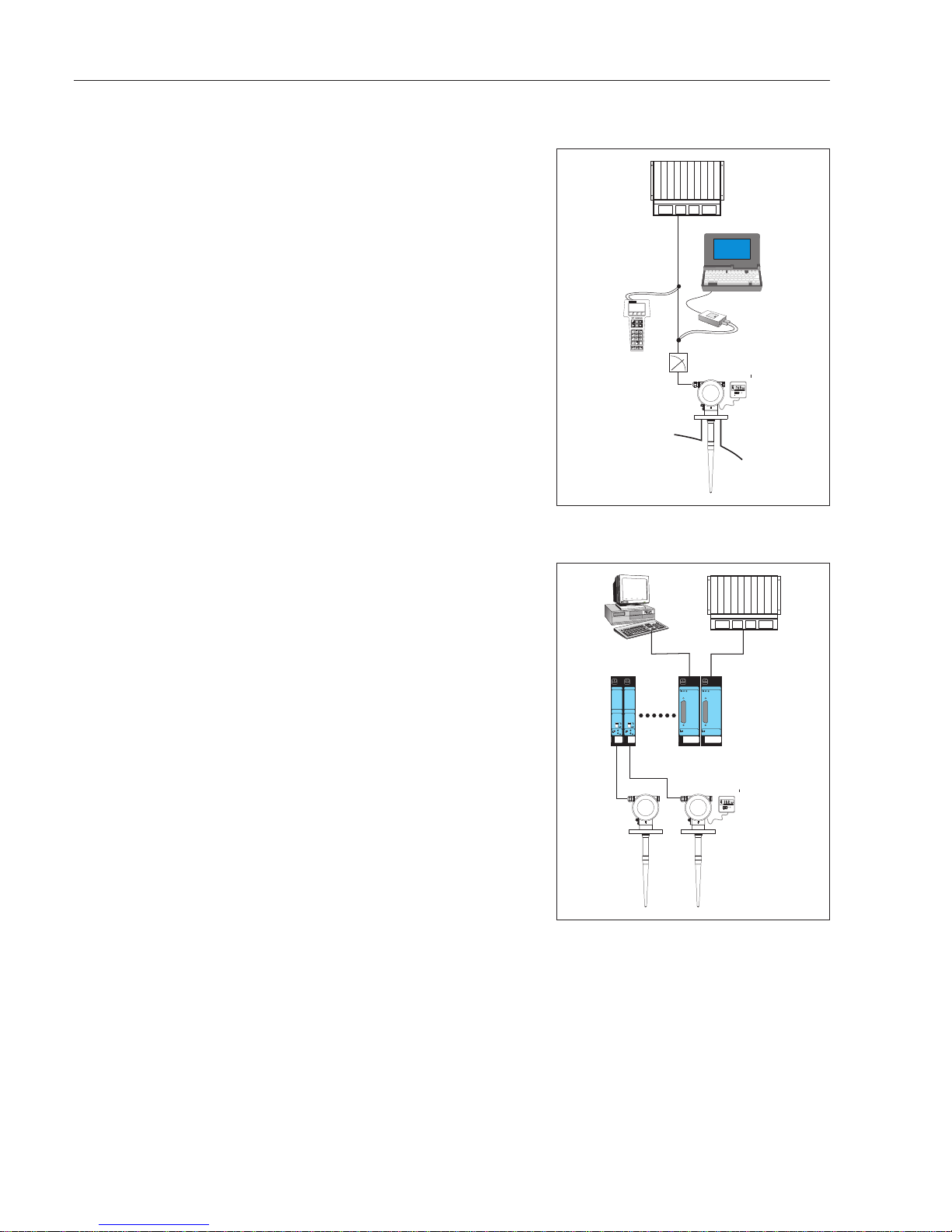
4...20 mA with HART
Version with passive 4...20 mA current
output and superimposed HART digital
signal.
•
Can be operated either on-site or
remotely with the HART handheld
DXR 275.
•
Alternatively, a personal computer,
Commuwin II and Commubox FXA 191
can be used.
•
Loop-power is provided by a PLC or
power supply unit.
System integration via
Rackbus
Several Micropilot transmitters (or other
devices with HART output) can be linked to
a supervisory bus system with a gateway
ZA.
•
One FXN 672 interface module is
required for each transmitter.
•
Gateways are available for MODBUS,
PROFIBUS, FIP, INTERBUS etc..
•
Both on-site and remote operation are
possible, e.g. with Commuwin II (CW II).
I
O
V
H
+
VH
BA171Y11
DXR
275
4...20 mA
with HART
PLC
loop power
Commubox
with laptop
operating
and display
module
VU 330
FXN 671
mA1
+
FXN 671
mA1
+
V
H
+
VH
ZA672 ZA672
BA171Y11
FXN
672
4...20 mA with HART
PLCPC with
CW II
operating
and display
module
VU 330
busRS 232C
Gateway to
MODBUS, FIP,
PROFIBUS,
INTERBUS etc..
Chapter 1 Introduction Micropilot FMR 231
8 Endress+Hauser
Page 11
2 Installation
2.1 Mounting in a tank
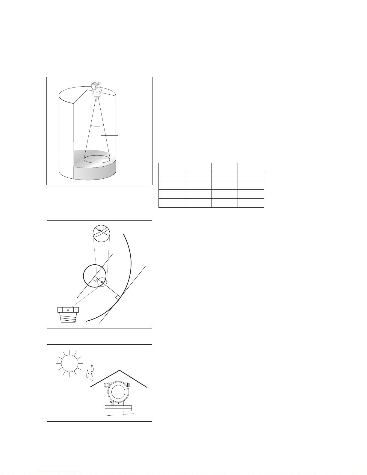
General notes
The microwaves should arrive unhindered
at the product surface.
•
Every object within the beam gives an
echo. The nearer the object, the
stronger the echo.
•
Strong echoes which cannot be
avoided by selecting a different
mounting position interfere with the
measurement and must be suppressed
during calibration.
Beam cone
Distance Radius r Distance Radius r
5 m 1 m 16 ft 3ft
10 m 2 m 33 ft 6 ft
15 m 3 m 50 ft 9 ft
20m 4m 67ft 12ft
Alignment
When installed, the alignment mark to be
found on the flange or threadedconnection
of the Micropilot should point towards the
tank wall.
•
Distance from tank wall min. 30 cm
The alignment can be optimised using
V3H2 as described in Chapter 7.5.
Ambient temperature
The ambient temperature of the housing
must be within the following limits, see also
Chapter 9.
•
Housing F12:
standard operation: –40°C...80°C
EEx ia T6 –40°C...50°C*
•
Housing T12:
standard operation: –40°C...80°C
EEx e T6 –40°C...50°C*
*For full details see certificate.
A protective cover is available for outdoor
mounting, Part No. 543199-0001.
BA171Y16
Fittings within
the beam cause
false echoes
23°
r
BA171Y17
tank wall
if possible,
clearance
greater than
30 cm
alignment
mark points to
tank wall
flange
thread
BA171Y21
Use a protective coverwhen
mounting outdoors
Micropilot FMR 231 Chapter 2 Installation
Endress+Hauser 9
Page 12
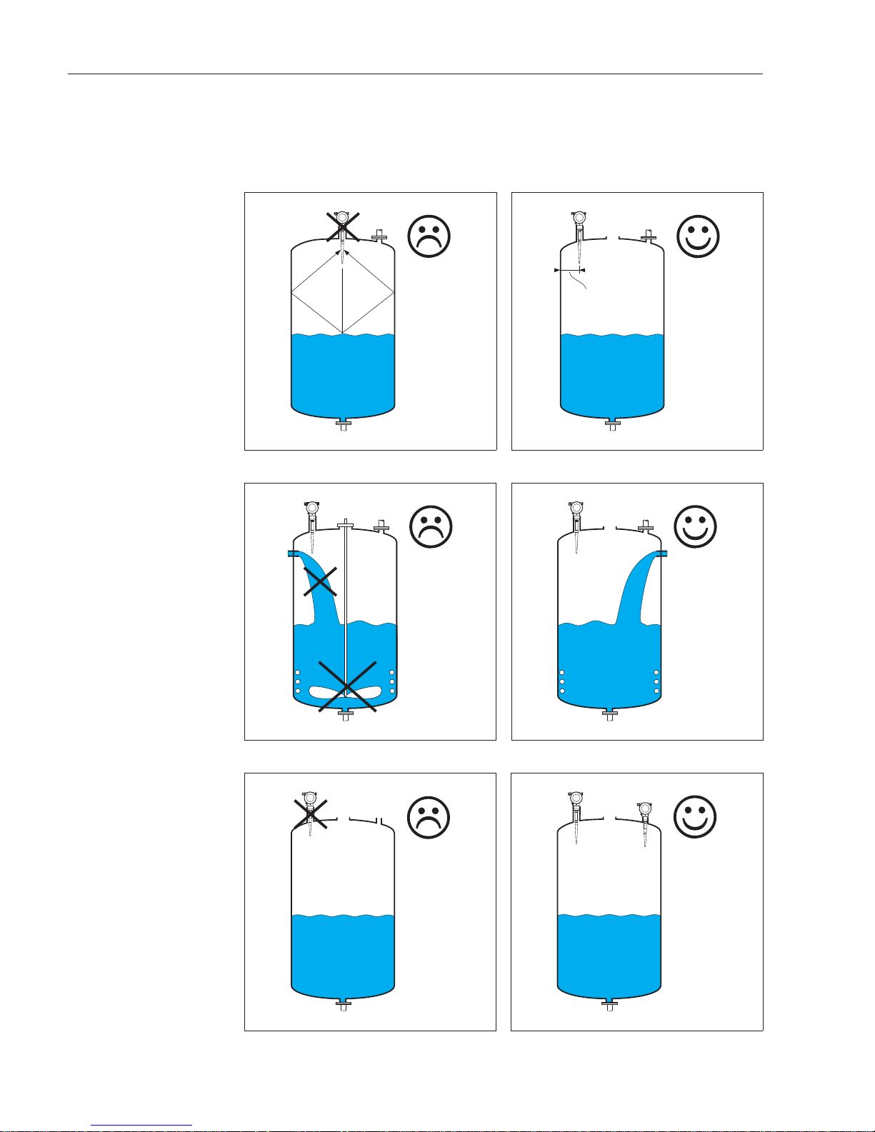
Mounting position
The ideal mounting position is as follows:
•
not in the middle of the tank
•
not above the filling stream
•
no fittings in beam
•
avoid vibration, direct high-pressure
cleaning and lateral loads.
min. 30 cm
BA171Y72
A decentral
position avoids
double echoes
BA171Y71
A central
position
strengthens
double echoes
BA171Y73
A positionaway
from the filling
stream will avoid
interference
echoes
Echos from
fittings are
suppressed
during
calibraatrion
BA171Y74
A positionabove
the fillingstream
will be subject to
interference
echoes
It is not possible
to measure in
tanks with
stirrers
BA171Y76
If the nozzle is too
long, noise will
reduce the signal
quality
BA171Y75
Use either a
longer antenna
or a shorter
nozzle –
see page 11 for
details
Chapter 2 Installation Micropilot FMR 231
10 Endress+Hauser
Page 13
Caution!
•
Applications in hazardous areas: electrostatic charging, e.g. rubbing clean, must be
avoided for standard PTFE and PTFE-clad antennas.
•
Always tighten the locking screw, since this connects the antenna to the ground
potential of the housing.
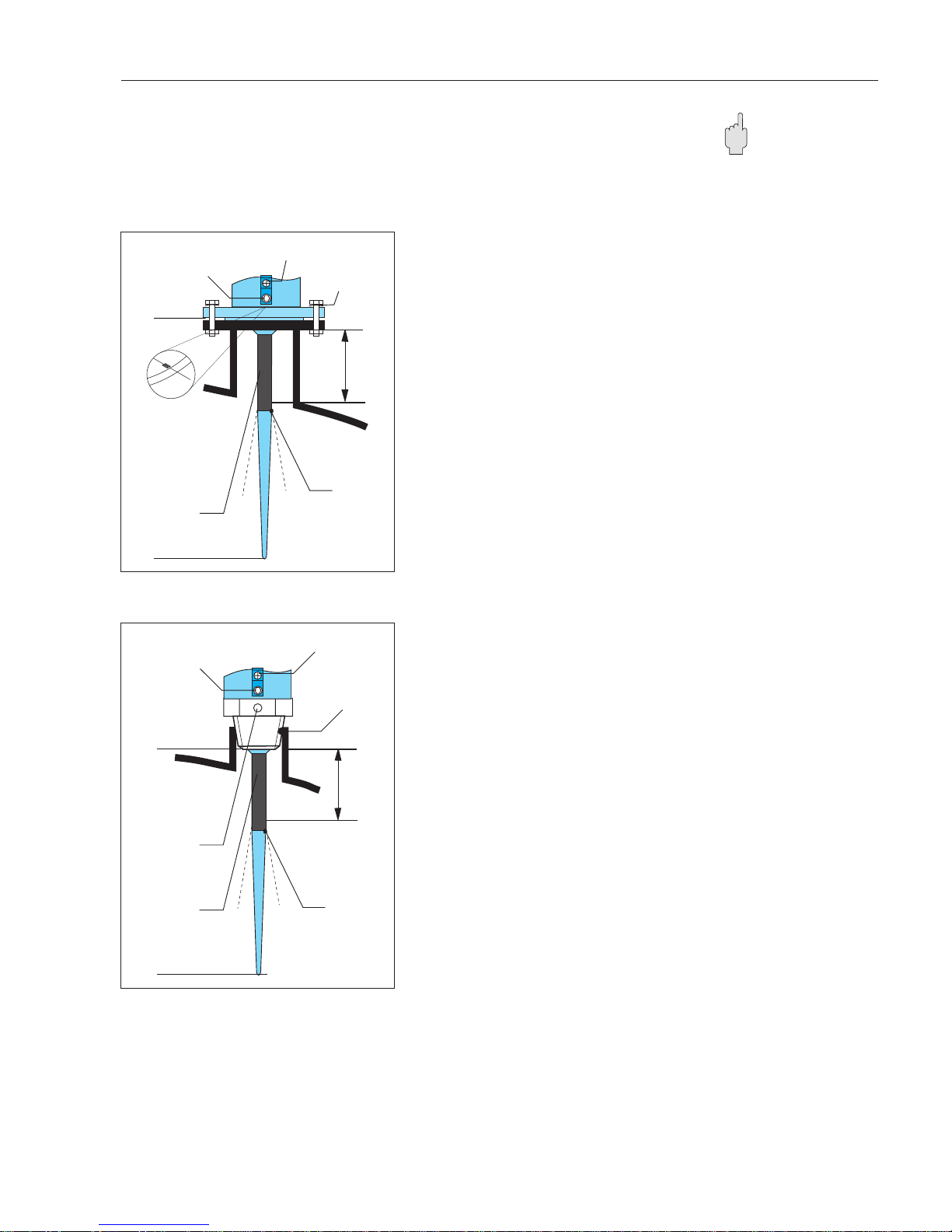
Nozzle
•
There is no restriction on nozzle
diameter provided that the length is
less than or equal to the inactive length.
•
Max. nozzle length hmax
100 mm for 100 mm inactive length,
250 mm for 250 mm inactive length.
•
The alignment mark on the flange
should point towards the tank wall.
•
After mounting, the housing can be
turned through 350° for convenient
access to the display and connection
compartment. The locking screw must
be loosened before turning.
•
Tighten the locking screw after turning.
Threaded connection
•
The hexagonal nut (AF 60) is used to
screw the transmitter in position.
•
Use e.g. a PTFE tape to seal the
process connection.
•
The alignment point on the threaded
connection should point towards the
tank wall.
•
After mounting, the housing can be
turned through 350° for convenient
access to the display and connection
compartment. The locking screw must
be loosened before turning.
•
Tighten the locking screw after turning.
BA171Y18
ground terminal
locking screw
datum point of
measurement
h
max
100 mm
or
250 mm
beam
launched
here
mark points to
tank wall
max.level
use spring
washers for
cladded
flange
inactivelength
BA171Y19
mark points to
tank wall
max.level
datum point of
measurement
locking screw
ground terminal
sealing tape
h
max
100 mm
or
250 mm
beam
launched
here
inactivelength
Caution!
Micropilot FMR 231 Chapter 2 Installation
Endress+Hauser 11
Page 14
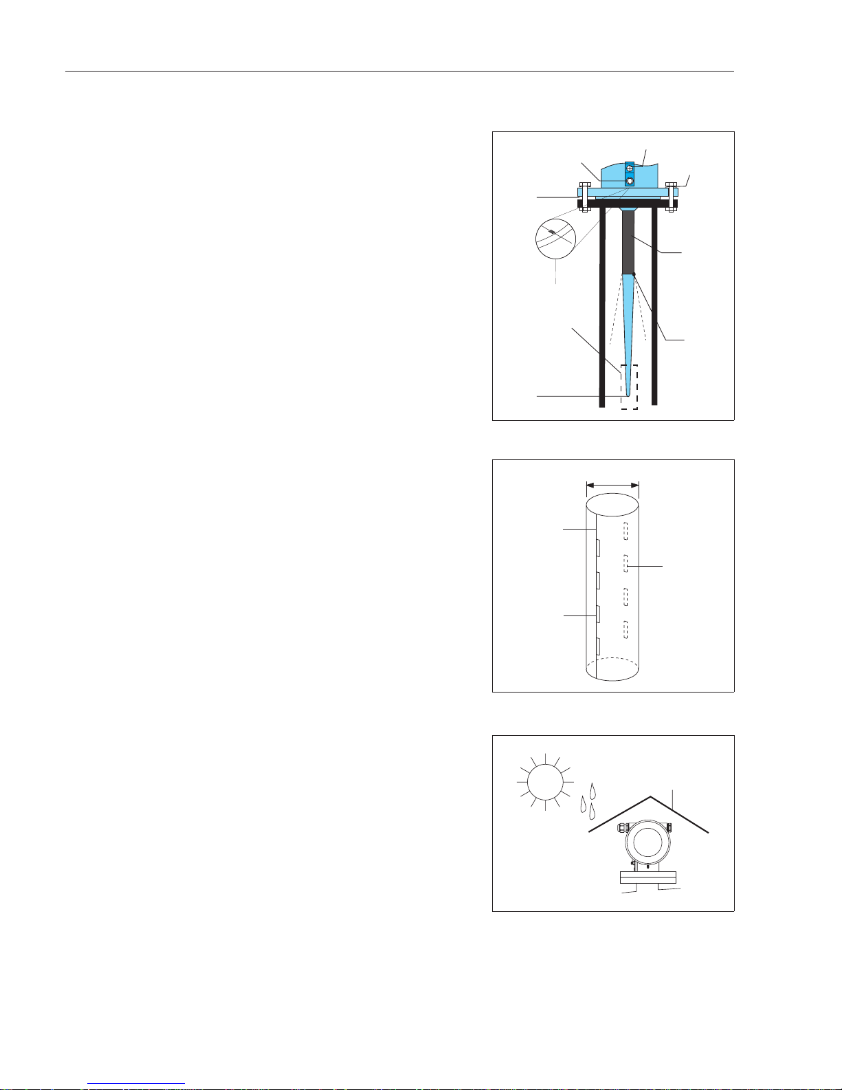
2.2 Mounting in stilling wells
Installation
Mount the antenna perpendicular and in
the centre of the well.
•
Slight unevenness of the well surface or
light build-up do not influence the
measurement
•
Measurements also possible through
open ball valves.
•
The alignment mark to be found on the
flange should point towards the slots.
•
After mounting, the housing can be
turned through 350° for convenient
access to the display and connection
compartment. The locking screw must
be loosened before turning.
•
Tighten the locking screw after turning.
.
Stilling well design
To ensure highest accuracy, the stilling well
should be designed as follows.
•
Metal construction
•
Constant diameter.
•
If possible, welding seam along axis of
slots.
•
Slots offset at 180° (not 90°), deburred
•
Slot width max. 1/10 of pipe diameter.
The length and number of slots has no
effect on the measurement.
Ambient temperature
The ambient temperature of the housing
must be within the following limits, see also
Chapter 9.
•
Housing F12:
standard operation: –40°C...80°C
EEx ia T6 –40°C...50°C*
•
Housing T12:
standard operation: –40°C...80°C
EEx e T6 –40°C...50°C*
*For full details see certificate.
A protective cover is available for outdoor
mounting, Part No. 543199-0001.
BA171Y77
inactive
length
100 mm
or
250 mm
locking screw
datum point for
measurement
alignment mark
pointing towards
the slots
spring
washer
for
cladded
flange
beam
launched
here
ground terminal
max.level
d
BA171Y22
if possible
welded along
axis of slots
slots offset
by 180°
slot width
max.
1
/10of
pipe diameter
BA171Y21
Use a protective cover when
mounting outdoors
Chapter 2 Installation Micropilot FMR 231
12 Endress+Hauser
Page 15
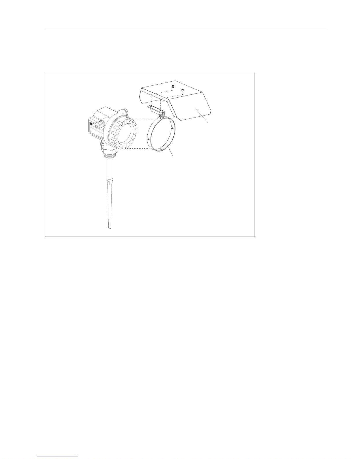
2.3 Protective cover
A protective cover is available for outdoor mounting, Part No. 543199-0001. The scope
of delivery comprises the cover and clamping ring.
ENDRESS+HAUSER
MICRO
P
ILOTII
ENDRESS+HAUSER
MICROPILOTII
IP65
IP65
OrderCode:
Ser.-No.:
OrderCode:
Ser.-No.:
Messber
eich
Measuringrange
Messbereich
Measuringrange
U16...36VDC
4...20mA
U16...36V DC
4...20mA
max.20m
max.20m
MadeinGermany Maulburg
T>70°C:
A
t >85°C
T >70°C:
A
t >85°C
BA171Y78
clamping ring
protectivecover
Micropilot FMR 231 Chapter 2 Installation
Endress+Hauser 13
Page 16
3 Connection
General notes The Micropilot is a loop-powered transmitter with 4...20 mA analogue output and
superimposed HART signal. Note the following before connecting up:
•
The power supply rating must correspond to that on the nameplate.
•
Turn off the power before connecting up.
•
Connect the external ground terminal of the transmitter to the plant grounding
system before connecting up.
•
Always tighten the locking screw, since this connects the antenna to the ground
potential of the housing.
Hazardous areas If the measuring system is to be installed in a hazardous area, local regulations, national
guidelines and the specifications inthe certificate are tobe observed.The specified cable
gland must be used.
For certified transmitters, the explosion protection is realised as follows:
•
Housing F12: EEx ia.
The power supply must be intrinsically safe.
•
Housing T12: EEx e m.
The housing must be integrated into the plant grounding system.
The power must be switched off before the connection compartment is opened.
The electronics and current output are galvanically isolated from the antenna circuit.
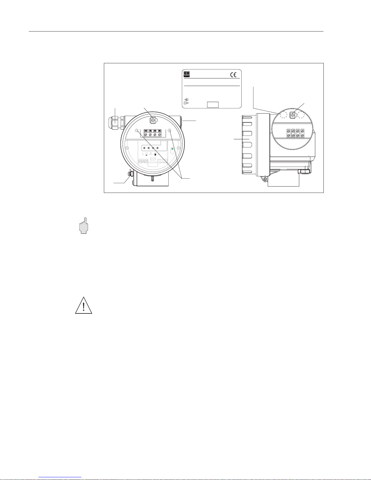
Connection Connect up the Micropilot as follows:
•
Switch off power.
•
Unscrew lid of housing or connection compartment.
•
For F12 housing: If appropriate, remove VU 330.
Remove cover plate to connection compartment.
•
Pull out terminal module with plastic loop.
•
Thread cable through cable gland or conduit
•
Connect up, see wiring examples.
•
Push terminal module back into place.
•
For F12 housing: Screw cover plate to connection compartment
If appropriate, stow away VU 330.
•
Screw on housing or connection compartment lid and screw cable gland or
conduit tight.
•
Switch on power.
Caution!
1
234
–
+
–
+
1
234
ENDRESS+HAUSER
MICROPILOT II
Order Code:FMR231-CEGGJ1A1A
Ser.-No.:PIZ0187
IP 65
EEx ia
Messbereich max.20 m
Measuring range
PN max 15 bar
T max. 150°C
antenna
BZT G133
414J
T < 80°C
A
U 16...30 DC
4...20 mA
Cable gland
Nameplate
external
ground
terminal
Connection compartment
behind cover plate –
loosen screws
BA171Y23
2nd cable entry
Operating elements in
display compartment
ground
terminal
HousingT12Housing F12
2x cable entries
at the rear
Fig.3.1
Micropilot connection
compartments and nameplate
Warning!
Chapter 3 Connection Micropilot FMR 231
14 Endress+Hauser
Page 17
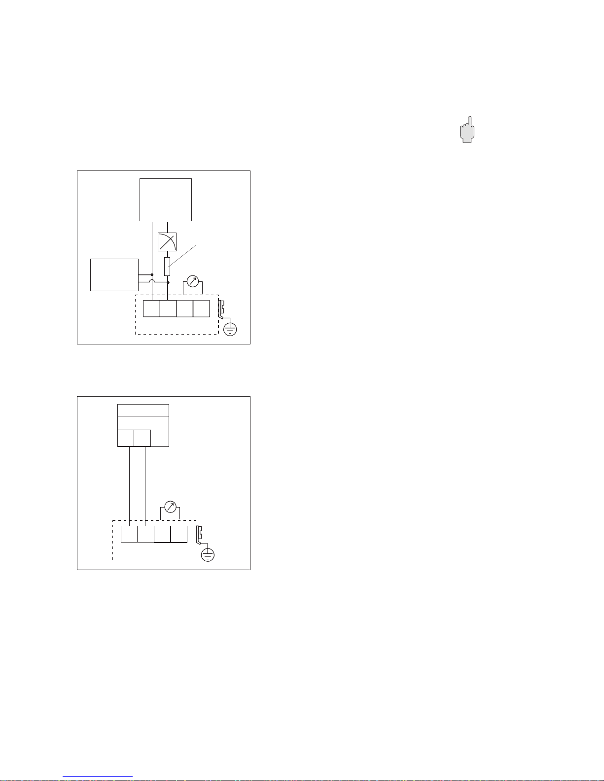
3.1 Wiring examples
The following figures show wiring examples for typical applications: In general:
•
If possible, ground both ends of the signal line screening. If this is not possible,
ground at the sensor side only.
•
In hazardous areas, the signal line may be grounded at the sensor side only.
Observe the instructions in the certificate.
4...20 mA with HART
Use screened, twisted pairs.
•
Min. load for HART 250 Ω
•
Max. load:
Housing F12: 1100 Ω, for EEx ia 820 Ω
Housing T12: 750 Ω, for EEx e 750 Ω.
•
Power
(load dependent, see Chapter 9.2.)
Housing F12
standard 16...36 VDC
EEx ia 16...30 VDC
Housing T12
standard 16...30 VDC
EEx e 16...30 VDC
System integration via
4...20 mA with HART
System Integration via interface FXN 672
and Rackbus gateway ZA 67x.
•
Power: supplied by FXN 672
Screened, twisted pairs are recommended
for the loop-power line.
1234
L- L+
I+ I-
BA171Y24
optional PLC
with active
output
power
plant
ground
DXR 275
or
FXA 191
communication
resistor
test sockets
(via interlock
diode)
Caution!
1
d4
ZA 67x
FXN 672
d2
234
L- L+
I+ I-
BA171Y25
plant
ground
Rackbus
Micropilot FMR 231 Chapter 3 Connection
Endress+Hauser 15
Page 18
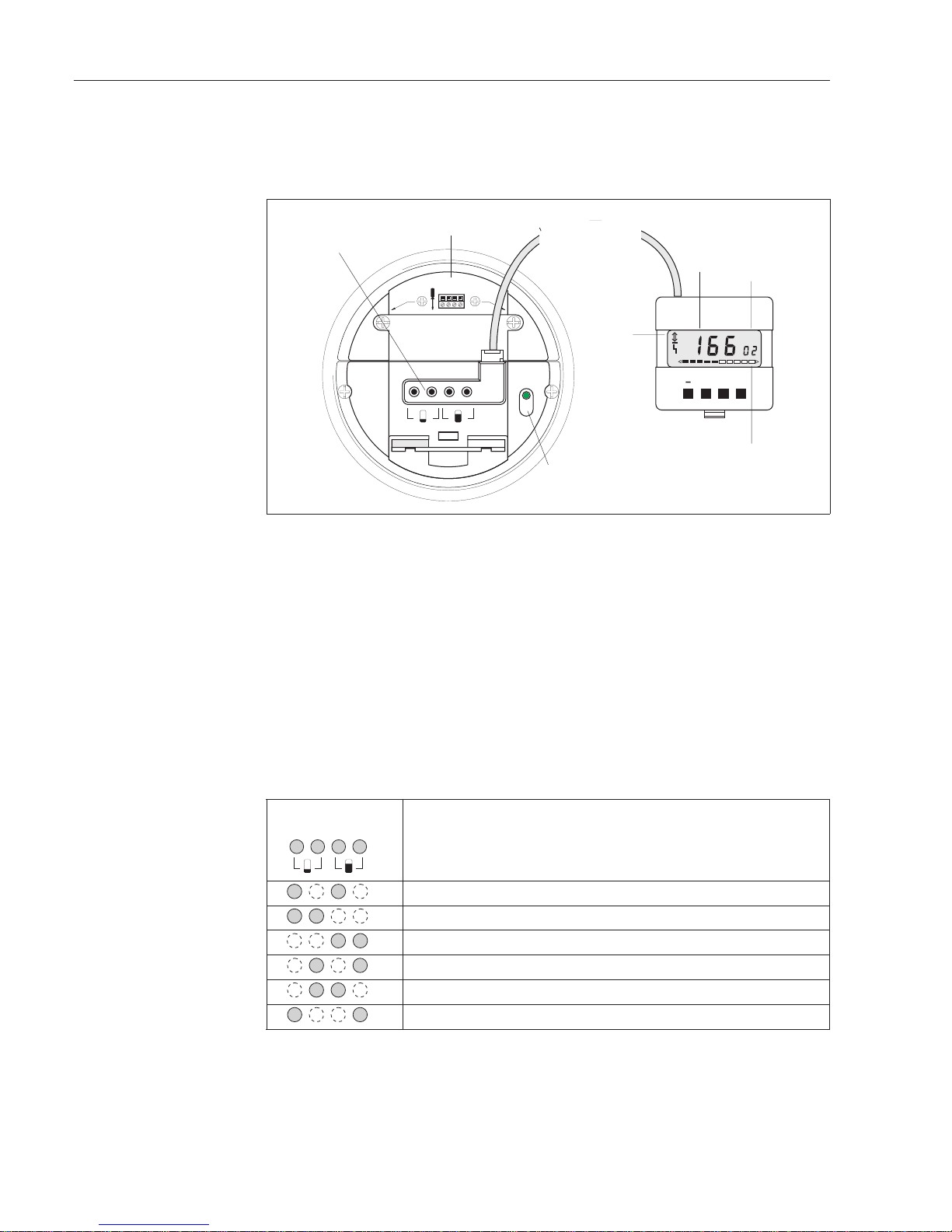
4 Operation
4.1 On-site operation
For the F12 housing, the operating elements are located within the transmitter housing
and can be operated when the cover is open. The T12 housing has a separate display
compartment which also can be opened in hazardous areas. The Micropilot has four
keys and an LED.
•
The LED flashes when an entered value is registered as well as during the
suppression of interference echoes. During operation it remains off.
•
The device keys allow the basic calibration of the Micropilot, but are deactivated
when the operating and display module VU 330 is connected.
Operation without the
VU 330
The function of the device keys when the operating and display module is not connected
is summarised in the table below. The two keys must always be pressed simultaneously.
The keys are used as follows, see Chapter 5:
Terminal
V H
V+ H
–
+
–
+
BA171Y26
bargraph
(current output/edho quality)
indicator
communication
fault
Operating and display module VU 330
matrix position
green LED
device
operating
keys
measured
not presentwith housing
T12
Fig.4.1
Operating elements of
Micropilot FMR 231
Keys Function
Reset to factory settings, see Chapter 7.9
Empty calibration, see Chapter 5
Full calibration, see Chapter 5
False echo suppression, see Chapter 5
Lock parameter entry, see Chapter 5
Unlock parameter entry, see Chapter 5
+
+
__
Chapter 4 Operation Micropilot FMR 231
16 Endress+Hauser
Page 19
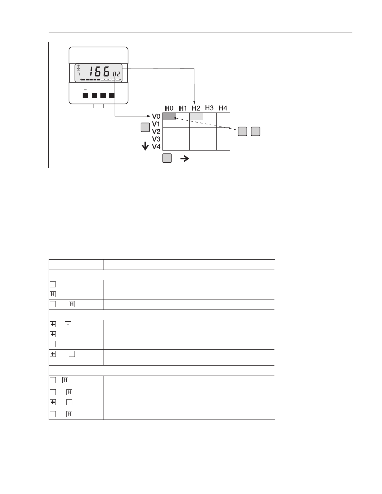
Operation with the
VU 330
If the Micropilot is equipped with an operating and display module VU 330, then it is
operated via a 10 x 10 operating matrix.
•
Each row is allocated to a particular function,
•
Each field sets or displays one parameter.
On-site operation with the operating and display module andcommunication both access
the same matrix. This is to be found in Chapter 10. If the HART handheld DXR 275 is
used, the transmitter is operated by a menu which is derived from this matrix.
The table below summarises the key functions of the operating and display module
VU 330.
V
H
VH
+
VH
V+ H
BA171Y27
Fig.4.2
Matrix operation using the
operating and display module
VU 330
Keys Function
Selection of matrix field
Selection of vertical matrix position
Selection of horizontal matrix position
and When V and H are pressed simultaneously the display springs to V0H0
Parameter entry
or Activates selected matrix position. The selected digit flashes.
Changes the value of the flashing digit by +1
Changes the value of the flashing digit by –1
and Sets the parameter just entered back to its original value, provided it has not
already been registered
Registration of the entry
or or
and
Registration of the entry and quitting of the matrix field
Registration of entry and jump to field V0H0
and or
and
+ and V lock entries,
– and H unlock entries, see Section 6.7
V
V
V
V
V
Micropilot FMR 231 Chapter 4 Operation
Endress+Hauser 17
Page 20
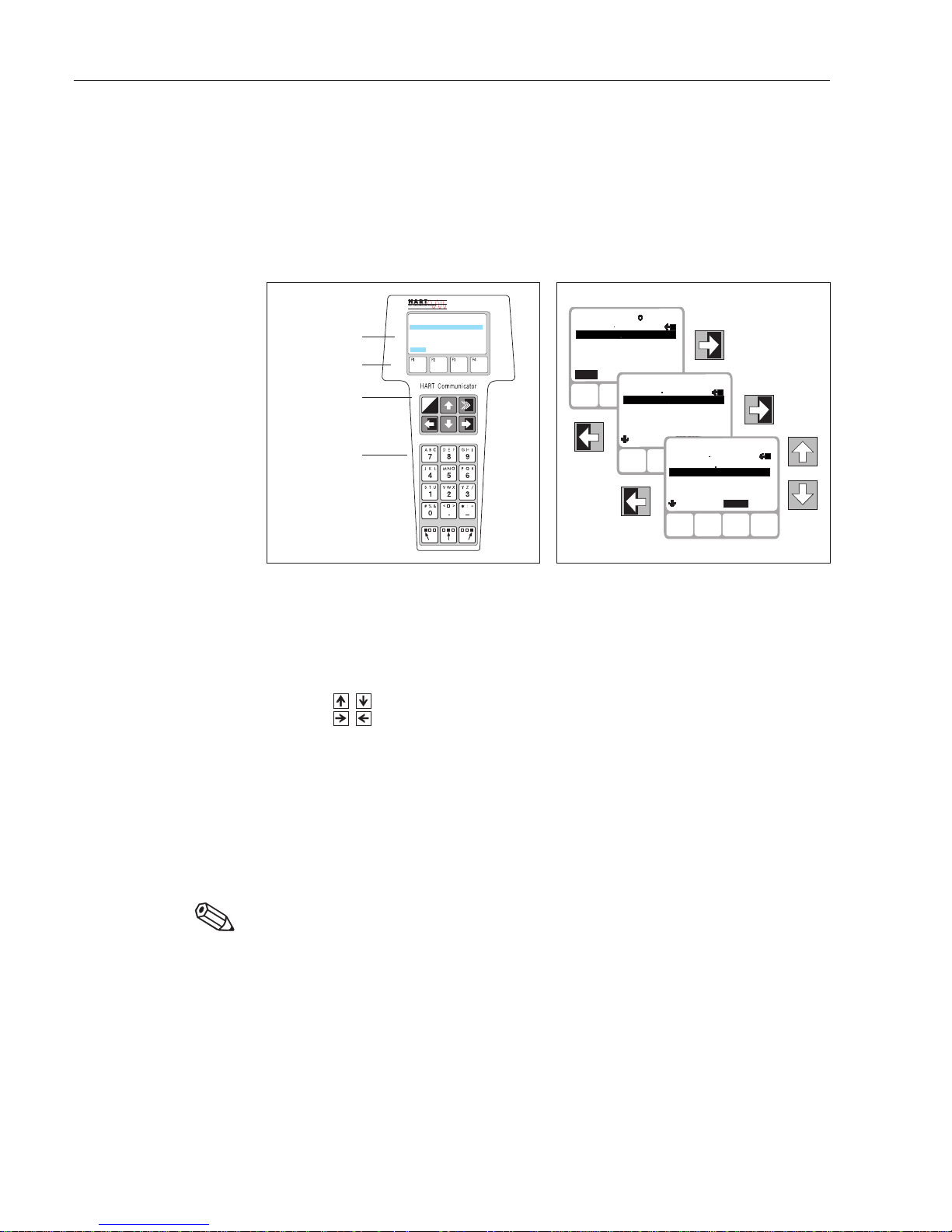
4.2 Remote operation
The Micropilot can be remotely operated via the communication interface 4...20 mA with
HART.
For HART, the operation depends on the measuring system.
•
For computer operation via Commubox FXA 191 or FXN 672 and gateway, the
operating matrix is used, see page 17.
•
For operation via handheld, a menu is used.
HART handheld DXR 275 The operation of the HART handheld DXR 275 is described in the manual supplied with
it.
The Group Select menu calls the matrix. The rows are the menu headers. Parameters
are set in the roll-down menus.
•
Keys , navigate up and down the menu.
•
Keys , change to the previous or to the following menu.
•
Parameters are entered by the corresponding keys.
– SEND registers the entries
•
Keys F1 - F4 call the displayed functions, e.g. HOME.
In the procedures described in this manual, the DXR 275 menu lines appear in the
"significance" column. Chapter 10 contains a listing ofmenu positions with corresponding
matrix fields.
Note!
•
The HART device description Version 2.0 for Micropilot FMR 231 must be loaded in
the DXR 275 before the device can be operated by the handheld. Updates of the
device descriptions can be obtained from Endress+Hauser.
I
O
FMR 231:LIC0001
Online
1 >GroupSelect
2PV 8.7m
HELP
BA171Y28
parameter entry keys
LC display with
menu texts
menu selection
keys
function keys
Fig.4.3
Operating elements and key
functions of the HART handheld
DXR 275
F1 F4F2 F3
FMR231: LIC0001
Online
2 PV 8.7m
HELP
1->Group Select
F1 F4F2 F3
FMR231 : LIC0001
2 Linearisation
3 Ext. Calibration
4 Service
5 Operating mode
Group Select
1->Calibration
HOME
F1 F4F2 F3
FMR231: LIC0001
3 Full Calibration
4 Application Parameter
5 Output Damping
Calibration
1 Measured Value
2->Empty Calibration
HOME
BA171Y29
Note!
Chapter 4 Operation Micropilot FMR 231
18 Endress+Hauser
Page 21

Commuwin IIA full description of the operating program Commuwin II is to be found in operating
instructions BA 124F. All Commuwin II functions are supported. The "envelope curve"
cannot be displayed. The transmitter is configured either via the operating matrix or the
graphic interface.
ConnectionThe table summarises the Commuwin connections,
Note!
•
Micropilot transmitters with HART interface can also be configured on site via the
keys. If the device keys are used to lock the matrix, then parameters cannot be
entered remotely via communication.
•
The Micropilot FMR 231 device description Version 2.0 is required for operation with
Commuwin II, see Operating Instructions BA 124F.
V1
V Calibration0
8.00
EMPTY CALIBRATION
7.50
FULL CALIBRATION
0
LINEARISATION
1
ECHO SUPPRESSION
1
TAB LE NO.
7.2
SUPPRESSION DIST.
0
ENTER LEVEL
27
ECHO QUALITY
67.5%
MEASURED VALUE
V Linearisation2
V Ent.calibration3
V4
V5
V6
V Service7
FMR 231
BA171E31
Fig.4.4
Device menu in Commuwin II
Note!
Interface Hardware Server Live list
HART Commubox 191 set to HART
Computer with RS-232C port
HART Connected device only
FXN 672 interface module
Gateway for MODBUS,
PROFIBUS, INTERBUS, FIP etc.
Computer with RS-232C port or
PROFIBUS card
ZA 673 for
PROFIBUS
ZA 672 for
others
List of all connected Rackbus
devices – select the FXN 672 via
its bus address
Micropilot FMR 231 Chapter 4 Operation
Endress+Hauser 19
Page 22

Graphical support mode The graphical support mode is called via the Device menu. Thus offers an alternative
method of configuring the Micropilot. Various pictures are offered when the Graphics
menu is clicked. These correspond to the procedures described in Chapter 6.
•
Status: software version, measuring point tag, diagnosis code and measured
value are displayed.
•
Commissioning: reset, measuring point tag, etc.
•
Basic calibration for tank: procedure for basic calibration in tanks.
•
Basic calibration for stilling wells: procedure for basic calibration in stilling wells.
•
Basic calibration Step 2: procedure for false echo suppression.
•
Technical units: settings for linear relationships.
•
Safety parameters: configuration of the analogue output for normal and failure
operation.
•
Service: parameters required for service call.
A linearisation can be called from the matrix window.
Off-line operation Commuwin also allows the Micropilot to be configured off-line. After all parameters have
been entered, the file generated can be loaded into the connected Micropilot. This can
now be commissioned by simply running the echo suppression procedure.
Up-/Download This function allows the parameters of an already configured Micropilot FMR 231 to be
loaded and stored in Commuwin II. If several Micropilots (with the same software version)
have to be configured in the same way, the parameters can now be downloaded into the
devices. In this case as well, an echo suppression must be made when the devices are
commissioned.
It is not possible to up and download parameters between Micropilots with different
software versions.
Graphical support - Basic calibration -Step 1-
EMPTY CALIBRATION
2.
3.50
FULL CALIBRATION
3.
3.00
APPLICATION
LOCK MATRIX
4.
1.* Code "333" Code >< "333"
4.* "0": Tank...approx. 7 m
"1": Tank...approx. 1.5 m
"2": Tank...approx. 7 m, DC<10
"3": Tank7 m... 20 m
1.
1
333
3
2
100%
20mA
0%
4mA
BA171E32
Abb.4.5
Graphic support window in
Commuwin II
Chapter 4 Operation Micropilot FMR 231
20 Endress+Hauser
Page 23

5 On-site calibration without display VU 330
Test pathAn on-site calibration without the operating and display module VU 330 requiresa defined
level echo. In order to avoid the danger of acquiring an interference echo from a fitting
as the zero point, it is recommended that the calibration be made outside the tank along
a suitable test path.
•
The length of the test path must correspond to the required empty distance "E".
•
A suitable reflector, e.g. a flat wall, must be available.
•
The Micropilot is pointed at the wall about 1.5 m above the ground.
Calibration and echo
suppression
•
The datum point for the empty distance
"E" and the distance "D" is always the
lower face of the process connection.
# Keys Significance
1 Micropilot ready for operation in test zone
2 Reset
Wait 20 seconds
3 Set empty distance "E".
Wait 2 minutes,
press keys.
4 Set distance "D".
Wait 2 minutes,
press keys.
5 Mount Micropilot on tank
6 Empty tank (at least to "E")
7 Echo suppression.
Wait until green LED stops
flashing.
Result
•
E ≡ 4 mA (= 0%)
•
F ≡ 20 mA (= 100%)
Note!
•
Stilling wells cannot be calibrated using
device keys
+
+
__
D
E
BA171Y02
Step 3
Step 4
D
F
E
100%
20mA
0%
4mA
BA171Y31
Steps 5, 6 and 7
Note!
D
F
E
E
100%
20mA
0%
4mA
Test path free of obstacles and with
reflector,e.g., a wall
stable
seating for
Micropilot
90°
BA171Y34
height above
ground
approx..1.5 m
Fig..5.1
Calibration outside tank using
device keys
Micropilot FMR 231 Chapter 5 On-site calibration without display VU 330
Endress+Hauser 21
Page 24

Correction of measuring
range
•
The device must have been calibrated
and the echoes suppressed before the
measuring range can be corrected.
•
The new empty distance "E" may not
exceed that used for the calibration.
Otherwise a new calibration is
necessary, see page 19.
# Keys Significance
1 If appropriate calibration and echo
suppression, p. 19
2 Bring level in tank to "empty",
Wait 2 minutes
3 Empty calibration (4 mA)
= zero
4 Bring level in tank to "full",
Wait 2 minutes
5 Full calibration (20 mA)
= span
After correction of measuring range:
•
"Empty" level E ≡ 4 mA
•
"Full" level F ≡ 20 mA
Lock keys
In order to avoid accidental or
unauthorised changing of the settings, the
keys can be locked for new entries.
# Keys Significance
1 Lock operation:
2 Unlock operation:
After the keys have been locked:
•
All entries, including those via the
operating matrix, are blocked
(VU 330, DXR 275, Commuwin II).
The contents of the matrix fields can be
read, however.
•
Entries can only be unlocked by using
the appropriate key combination, see
above.
Note!
•
After the keys have been used, screw
on the housing cover.
+
+
__
+
+
__
D
F
E
100%
20mA
0%
4mA
BA171Y36
empty distance "E"
of calibration(old)
–
+
–
+
BA171Y35
Note!
Warning!
Chapter 5 On-site calibration without display VU 330 Micropilot FMR 231
22 Endress+Hauser
Page 25

6 Calibration with Display/Remote Operation
The chapter describes the basic calibration and other functions that can be set via the
operating matrix. The matrix can be accessed via:
•
Operating and display module VU 330
•
HART handheld DXR 275
•
Operating program Commuwin II.
The matrix operation using the operating and display module VU 330 is described. At
the start of every procedure, however, the HART handheld menu is shown, e.g.
➤ Simulation.
The chapter is structured as follows:
Start calibration
tank or
pipe
Chapter 6.1
Basic calibration
and false echo
suppression
Chapter 6.2
Basic calibration
and false echo
suppression
Chapter 6.3
Linearisation
Chapter 6.4
Analogue output
Chapter 6.5
Safety functions
Chapter 6.6
Lock/unlock
tank
stilling well
BA171Y68
Micropilot FMR 231 Chapter 6 Calibration with Display/Remote Operation
Endress+Hauser 23
Page 26

6.1 Basic calibration for tanks
After resetting the Micropilot to the factory settings (only required during commissioning),
enter the following parameters:
•
empty distance E, full distance F and application parameter A.
The datum point for the empty distance "E" is always the lower face of the process
connection. The full distance "F" may extend only as far as the antenna tip. The calibration
units are metres or feet, settable in V8H5 (0 = m, 1 = ft).
The user has a choice of four application parameters, see also Chapter 7.
Calibration
# VH Entry Significance
➤ Simulation
1 V9H5 333
VH
Reset
➤ Basic calibration
2 V0H1 E m/ft
H
Empty distance
3 V0H2 F m/ft
VH
Full distance
4 V0H3 A
VH
Application
parameter
0: up to 4 m
1: up to 1.5 m
2: up to 4 m, εr < 4
3: up to 20 m
5 V0H0
V0H9
Current level in %
or m/ft
False echo suppression
•
With the tank empty, check whether
distance displayed in V0H8
corresponds to the distance to the
product surface "D".
# VH Entry Significance
1 Empty vessel as far as possible
➤ Basic calibration
2 V0H8 ****
VH
Check value
3 Values correspond?
Echo is level echo➝ procedure A
Suppression up to echo
Values do not correspond?
Echo is false echo ➝ Procedure B
Suppression inclusive echo
Code Application Significance
0 Tank up to 74 m high For slow changes in level (factory setting)
1 Tank up to 1.5 m high For small tanks with rapid changes in level
2 Tank up to 7 m high, ε
r
< 10 For Product Class B, see page 7
3 Tank from 7 m to 20 m high For high storage tanks
F
E
100%
20mA
0%
4mA
BA171014
V0H8
D
BA171Y37
false echo
levelecho
Chapter 6 Calibration with Display/Remote Operation Micropilot FMR 231
24 Endress+Hauser
Page 27

Procedure A
Echo is level echo
# VH Entry Significance
➤ Extended calibration
1 V3H0 2
H
2: up to echo
2 V3H1 ****
+
H
Register value
when display
flashes
3 Wait approx. 3 minutes until the fault indicator
disappears.
Procedure B
Echo is false echo
# VH Entry Significance
➤ Extended calibration
1 V3H0 3
H
3: inclusive echo
2 V3H1 ****
+
H
Register value
when display
flashes
3 Wait approx. 3 minutes until the fault indicator
disappears.
➤ Basic calibration
4 V0H8 ****
VH
Check value again
5 Repeat steps 2...4 until V0H8 = D.
Then Procedure A.
Note!
•
The LED and fault indicator flash while the false echo suppression map is being
recorded. Warning E514 appears.
•
There is a further method of recording a false echo suppression map (V3H0 = 4)
which is described in Chapter 7.6
Check echo quality
# VH Entry Significance
➤ Extended calibration
1 V3H2 ****
H
Echo quality
≥ 10: OK
<10: Optimise
alignment
Chapter 7.5.
Change
position.
After calibrationAfter calibration, the Micropilot measures level in %. The analogue output follows the
display in V0H0. The current values 4 mA and 20 mA are automatically assigned to the
levels 0% and 100%.
V0H8
D
BA171Y80
V H
V3H2 >10:
BA171Y70
V0H8
D
BA171Y80
Note!
Micropilot FMR 231 Chapter 6 Calibration with Display/Remote Operation
Endress+Hauser 25
Page 28

6.2 Basic calibration for bypass pipes and stilling wells:
After resetting the Micropilot to the factory settings (only required during commissioning),
enter the following parameters:
•
empty distance E, full distance F, application parameter A, microwave factor MF.
The datum point for the empty distance "E" is always the lower face of the process
connection. The full distance "F" may extend only as far as the antenna tip. The calibration
units are metres or feet, settable in V8H5 (0 = m, 1 = ft).
•
For Product Class B, it is recommended that the empty distance "E" is set 30 cm
above the tank bottom.
.
The microwave factor MF =
√1 – (X/d
2
),
whereby d = internal diameter of the pipe in mm
X = 925 at 5.8 GHz and 784 at 6.3 GHz (FCC approval)
The user has a choice of three application parameters, see also Chapter 7.4.
Calibration
# VH Entry Significance
➤ Simulation
1 V9H5 333
VH
Reset
➤ Basic calibration
2 V0H1 E m/ft
H
Empty distance
3 V0H2 F m/ft
VH
Full distance
4 V0H3 A
VH
Application
parameter
4: up to 7 m
5: up to 1.5 m
6: 7 m to 20 m
➤ Extended calibration
5 V3H3 MF
VH
Microwave factor
6 V0H0
V0H9
Current level in %
or m/ft
Version DN50 PN16 DN80 PN 16/40 DN 100 PN16 DN 150 PN16
MF (5.8 GHz) 0.8298 (d = 54.5) 0.9296 (d = 82.5) 0.9574 (d = 105.3) 0.9811 (d = 157.1)
Version ANSI 2"/150 lbs ANSI 3"/150 lbs ANSI 4"/150 lbs ANSI 6"/150 lbs
MF (5.8 GHz) 0.8151 (d = 52.5) 0.9281 (d = 81.7) 0.9574 (d = 105.3) 0.9811 (d = 157.1)
MF (6.3 GHz) 0.8459 (d = 52.5) 0.9394 (d = 81.7) 0.9640 (d = 105.3) 0.9840 (d = 157.1)
Code Application Significance
4 Stilling well up to 7 m long For slow changes in level
5 Stilling well up to 1.5 m long For short stilling wells with rapid level changes
6 Stilling well from 7 m to 20 m
long
For long stilling wells in high storage tanks
F
E
100%
20mA
0%
4mA
BA171Y03
30 cm from
tank bottom
for product
group B
Chapter 6 Calibration with Display/Remote Operation Micropilot FMR 231
26 Endress+Hauser
Page 29

False echo suppression
•
With the tank empty, check whether
distance displayed in V0H8
corresponds to the distance to the
product surface "D".
# VH Entry Significance
1 Empty vessel as far as possible
➤ Basic calibration
2 V0H8 ****
VH
Check value
3 Values correspond?
Echo is level echo➝ procedure A
Suppression up to echo
Values do not correspond?
Echo is false echo ➝ Procedure B
Suppression inclusive echo
Procedure A
Echo is level echo
# VH Entry Significance
➤ Extended calibration
1 V3H0 2
H
2: up to echo
2 V3H1 ****
+
H
Register value
when display
flashes
3 Wait approx. 3 minutes until the fault indicator
disappears.
Procedure B
Echo is false echo
# VH Entry Significance
➤ Extended calibration
1 V3H0 3
H
3: inclusive echo
2 V3H1 ****
+
H
Register value
when display
flashes
3 Wait approx. 3 minutes until the fault indicator
disappears.
➤ Basic calibration
4 V0H8 ****
VH
Check value again
5 Repeat steps 2...4 until V0H8 = D.
Then Procedure A.
Note!
•
The LED and fault indicator flash while the false echo suppression map is being
recorded. Warning E514 appears.
•
There is a further method of recording a false echo suppression map (V3H0 = 4)
which is described in Chapter 7.6
Check echo quality
# VH Entry Significance
➤ Extended calibration
1 V3H2 ****
H
Echo quality
≥ 10: OK
<10: Optimise
alignment
Chapter 7.5.
Change
position.
After calibrationAfter calibration, the Micropilot measures level in %. The analogue output follows the
display in V0H0. The current values 4 mA and 20 mA are automatically assigned to the
levels 0% and 100%.
D
V0H8
BA171Y39
DD
V0H8
V0H8
BA171Y81
Procedure A
Procedure B
V H
V3H2 >10:
BA171Y70
Note!
Micropilot FMR 231 Chapter 6 Calibration with Display/Remote Operation
Endress+Hauser 27
Page 30

6.3 Linearisation
Linearisation mode A linearisation describes the relationship between level and the tank volume or product
weight and allows a measurement in technical units, e.g. metres, hectolitre, tonnes etc.
Afterwards, the measured value is displayed in the selected units in V0H0 and the
analogue output is proportional to the volume or weight. The table below lists the
linearisation modes.
Warnings During entry of the table, an error message is generated and the device indicates an
alarm. After the curve has been entered, it is checked for plausibility. The following
warnings and alarms can appear.
De-activation A linearisation table can be deactivated by setting V2H0 = 0 (m/ft) or 5 (linear). It is not
deleted and can be re-activated at any time by setting V2H0 = 1.
The setting V2H0 = 4 deletes the entire table. The linearisation mode "linear" (V2H5 = 5)
is automatically selected.
Note!
•
The values in V2H5, V0H5 and V0H6 must be changed as necessary.
Note!
Entry
V2H0
Linearisation mode Significance
0
Level Linear display of level in m or ft.
2
Manual entry Max. 30 pairs of values, level and volume, are entered as the
linearisation curve.
3
Semi-automatic entry In the case of semi-automatic entry, the tank is filled in stages. The
device automatically displays the level, the associated volume is
entered manually.
5
Linear relationship Factory setting. The relationship between the technical units and
level is linear. By entering the max. volume or weight, the measured
value is output in the technical units chosen by the user.
In addition, V2H0 offers the functions:
1
Activate table The entered linearisation table only comes into effect after it has
been activated.
4
Delete table Before a new linearisation table is entered, any previously active
table must be deleted. On deletion the linearisation mode is
automatically set to linear.
Code Type Significance
E602 Warning The linearisation curve does not rise continuously.
The number of the last valid pair automatically appears in V2H1. All
value pairs from this number onwards must be re-entered.
E604 Warning The linearisation curve comprises less than two value pairs.
Enter more points.
E605 Alarm The manual linearisation table is incomplete
Disappears after activation of table.
Chapter 6 Calibration with Display/Remote Operation Micropilot FMR 231
28 Endress+Hauser
Page 31

Linear dependencyFor tanks with a linear dependency between level and volume or weight, technical units
can be set by entering the maximum volume or weight in V2H5 and V0H6.
# VH Entry Significance
➤ Linearisation
1 V2H0 5
H
Linear
2 V2H5 e.g. 500 kg
VH
Max. volume
Volumen/weight at
level F
➤ Basic calibration
3 V0H6 e.g. 500 kg
VH
Value for 20 mA
Volumen/weight at
level F
Result
•
Lower range-value E = e.g. 0 kg (4 mA)
•
Upper range-value F = e.g. 500 kg
(20 mA)
Linearisation tableIf volume or weight is not proportional to level within the set measuring range, then a
linearisation table must be entered before the measured value can be displayed in
technical units. The prerequisites are as follows:
•
The max. 30 value pairs for the linearisation curve are known
•
The level values must be entered in increasing order. The curve constantly
increases (monotonic).
•
The levels for the first and last points correspond to those of the empty and full
calibration (E and F)
•
The level points are entered in the units of calibration.
# VH Entry Significance
1 If no calibration yet see Section 6.1/6.2
➤ Linearisation
2 V2H0 4
H
Delete existing
curve
3 V2H0 2
H
Linearisation mode
"manual"
4 V2H1 e.g. 1
H
1st value pair
5 V2H2 e.g. 0 m/ft
H
Level point 1
6 V2H3 e.g. 0 kg
H
Volume/weight
point 1
7 Repeat steps 4...6 for up to 30 value pairs
8 V2H0 1
H
Activate
linearisation
➤Basic calibration
9 V0H6 e.g. 600 kg
VH
Value for 20 mA
Volumen/weight at
level F
10 V0H0
V0H9
Measured value in
technical units
Level in m/ft
F
E
BA171Y38
100%
0
V2H5
V0H6
level
technical
units
F
E
BA171Y41
F m/ft
0
Vmax
V0H6
levelm/ft
technical
units
Micropilot FMR 231 Chapter 6 Calibration with Display/Remote Operation
Endress+Hauser 29
Page 32

Horizontal cylinder A linearisation curve for a horizontal cylinder can also be entered manually by using the
table below:
•
Starting at the completely full tank (level/volume = 100%, calculate the % volume
for each level point.
Volume at L % level = Total volume x Volumen %
100
Tab.-No
V2H1
LevelV2H2 Volume V2H3
% m/ft % T. unit
10 0
2 10 5.20
3 20 14.24
4 30 25.23
5 40 37.35
6 50 50.00
7 60 61.64
8 70 74.77
9 80 85.76
10 90 94.79
11 100 100
Semi-automatic entry The tank is filled and the level automatically acquired. The associated volume must be
entered by hand.
# VH Entry Significance
1 If no calibration yet see Section 6.1/6.2
2 Fill tank step-by-step
➤ Linearisation
3 V2H0 4
H
Delete existing
curve
4 V2H0 3
H
Linearisation mode
"semi-automatic"
5 V2H1 e.g. 1
H
1st value pair
6 V2H2 ****
H
Current level
7 V2H3 e.g. 0.6 hl
H
Volume for V2H2
8 Repeat steps 2...7 for up to 30 value pairs
9 V2H0 1
VH
Activate table
➤ Basic calibration
10 V0H5 Volume at
"E"
H
Lower range-value
volume/weight
11 V0H6 Volume at
"F"
VH
Upper range-value
volume/weight
12 V0H0
V0H9
Measured value in
technical units
Level in m/ft
Note!
If the tank is emptied step-by-step, the following must be noted:
•
The number of points must determined before starting.
•
The first table no. = (30 – no. of points)
•
The entries in V2H1 must be made in descending order (last entry = 1).
F
E
100%
90%
80%
70%
60%
50%
40%
30%
20%
10%
0%
BA171Y43
F
E
BA171Y42
F m/ft
0
Vmax
V0H6
levelm/ft
technical
units
Note!
Chapter 6 Calibration with Display/Remote Operation Micropilot FMR 231
30 Endress+Hauser
Page 33

6.4 Analogue output
The analogue output can be set using the fields listed below. If required, a scaling or
inversion of the output can be set in V0H5 and V0H6.
Settings
Example:
Analogue output
# VH Entry Significance
➤ Operating mode
1 V8H1 e.g. 1
H
Output min. 4 mA
0: off
1: on
➤ Basic calibration
2 V0H4 e.g. 10
H
Output damping
3 V0H5 e.g. 40%
H
Value for 4 mA
4 V0H6 e.g. 70%
H
Value for 20 mA
5 V0H7 e.g. 0
VH
Safety alarm
0 = MIN
1 = MAX
2 = HOLD
BA171Y44
100%
0%
V0H6
level
V0H5
4mA 20mA
Field Parameter Significance
V8H1 Current output min 4 mA
0: off
1: on
Sets behaviour of analogue output. Default = 1.
0: 3.8...20.5 mA continuous output
1: as above, but 4 mA limit in normal operation
The ouput follows the setting in V0H7 if a fault is detected
V0H4 Output damping τ
0...255 s
Influences the time it takes for the analogue output to
react to a sudden change in level (63% of steady-state
value). Default 5 s. Increasing the value damps the effect
of e.g. rapid level changes on the measured value.
V0H5
V0H6
4 mA value
20 mA value
Lower range-value of analogue output
Upper range-value of analogue output
Entry in % or after a linearisation in technical units
V0H7 Safety alarm (Output on alarm)
0: MIN
1: MAX
2: HOLD
In order to signal an alarm, the measured value assumes
the selected value.
MIN = 3.8 mA; MAX = 22 mA
HOLD = holds last current value
V9Hß Current output Displays current value of analogue output
Micropilot FMR 231 Chapter 6 Calibration with Display/Remote Operation
Endress+Hauser 31
Page 34

6.5 Safety functions
The Micropilot offers the user the following safety functions:
Example:
Safety functions
# VH Entry Significance
➤ Operating mode
1 V8H3 e.g. 60
H
Delay time E641
2 V8H5 e.g. 1
H
Within safety
distance =
Alarm
Field Parameter Significance
V3H5 Window suppression Defines a distance measured from the datum point in
which no echoes are measured. It is used for suppressing
strong echoes in the immediate vicinity of the antenna,
see Chapter 7.7.
The default setting extends to the tip of the antenna.
A smaller distance cannot be entered.
V8H3 Delay on lost echo If the echo is lost, alarm E641 is output. V8H3 determines
the time which elapses between the loss of the echo and
the response of the Micropilot. Default = 30 s.
V8H5 In safety distance
0: Warning
1: Alarm
2: Alarm, self-holding
3: Reset 2
A safety zone extends 10 cm in front of the window
suppressiion zone. This is to warn, that if the level
continues to rise, the measurement will become invalid. If
product enters the safety zone, the Micropilot responds
according to the setting in V8H5:
0: Warning E643 is output: the device continues to
measure
1: Alarm E643 is output: measurement is suspended until
the product leaves the safety zone.
2: Alarm E643 is output: measurement is suspended until
the alarm is acknowledged.
3: Acknowledges the alarm in case 2..
V8H6 Plausibility
0: off
1: on
The plausibility check is automatically set after the entry of
the application parameter A:
off: application parameters 0 - 3
on: application parameters 4 - 6
When the plausibility check is activated, the current level
is checked against the previous level, in order to establish
whether the value is plausible .If this is not the case, error
code E643 is output and the Micropilot reacts according
to the setting in V8H5 – see also Chapter 7.8.
Chapter 6 Calibration with Display/Remote Operation Micropilot FMR 231
32 Endress+Hauser
Page 35

6.6 Locking/unlocking the matrix
After all parameters have been entered, the matrix can be locked.
•
On-site with the device keys, see Chapter 5, or
•
via the matrix by entering a three digit code not equal to 333 in V9H9.
(333 is the code for unlocking the matrix)
This protects the measuring point from accidental and unauthorised entries.
# VH Entry Significance
➤ Simulation
Lock
1 V9H9 e.g. 100
VH
Matrix locked
(except V9H9)
Unlock
2 V9H9 333
VH
Matrix unlocked
Note!
•
If the Micropilot is locked by means of the device operating keys, then the entire
matrix including V9H9 is locked. No parameters can be changed, not even via the
communication interface. The contents of the matrix fields can be read, however.
•
The matrix can only be unlocked by using the device operating keys on the
Micropilot.
BA171Y45
Note!
Micropilot FMR 231 Chapter 6 Calibration with Display/Remote Operation
Endress+Hauser 33
Page 36

6.7 Measuring point information
The following information about the measuring point can be read:
Communication level The matrix row "VA communication" can only be accessed via the the HART handheld
DXR 275 or Commuwin II.
Matrix field Display (or entry)
Measured value
V0H0
Principle measured value
V0H8
Distance to product surface
Bargraph shows echo quality: 1 segment = 5 dB
V0H9
Level before linearisation
Bargraph shows echo quality: 1 segment = 5 dB
Sensor data
V0H3
Application parameter
V0H5
Value for 4 mA
V0H6
Value for 20 mA
V2H0
Linearisation mode
V3H0
False echo suppression: 0 = factory set, 1 = customer set
V3H1
Dtance up to which echoes have been suppressed.
V3H2
Echo quality in dB: the higher, the better
V3H3
Microwave factor
V8H1
Currrent output min. 4 mA: 0 = off, 1 = on
V8H2
Unit of calibration: 0 = metre, 1 = feet
V8H3
Delay time on lost echo
V8H5
In safety distance: 0 = warning, 1 = alarm, 2 = alarm, self-holding
Information on measuring point
V9H3
xxyy: communications (xx) and software number (yy)
(xx = 80 = HART, yy = 10 = software version 1.0)
V9H4
HART communication address
Diagnosis
V9H0
Current diagnosis code
V9H1
Last diagnosis code
Matrix field Display (or entry)
VAH0
Measuring point Tag. No.
8 characters (ASCII) can be entered here
VAH3
Units of measured value (for handheld)
Chapter 6 Calibration with Display/Remote Operation Micropilot FMR 231
34 Endress+Hauser
Page 37

7 Trouble-Shooting
When the instructions in the manual have been followed correctly, the system must now
function. Should this not be the case, the Micropilot provides a number of possibilities
for analysing and correcting faults.
7.1 Self-monitoring
The self-monitoring system differentiates between alarms and warnings.
On an alarm
•
The fault indicator appears at the
operating and display module VU 330.
•
The analogue output responds
according to the settings in V0H7,
V8H3 and V8H5, see table below.
•
The bargraph follows the analogue
output.
An error code is displayed at matrix
position V9H0 to help locate the fault. V9H1
indicates the previous error code.
On a warning
•
The fault indicator appears at the
operating and display module VU 330.
•
The Micropilot continues to measure.
An error code is displayed at matrix
position V9H0 to help locate the fault. V9H1
indicates the previous error code.
Analogue output
The analogue output responds according to the setting in V0H7. If the Micropilot has
been configured with the device keys (no VU 330, DXR 275 or Commuwin II), then the
analogue output goes to MAX (= 22 mA) on a fault.
V H
V+ H
BA171Y33
fault indicator
V H
V+ H
BA171Y46
Faultindicator
Analogue output at V0H7 = 0 (MIN) V0H7 = 1 (MAX) V0H7 = 2 (HALTEN)
Current
3.8 mA 22 mA last current held
Micropilot FMR 231 Chapter 7 Trouble-Shooting
Endress+Hauser 35
Page 38

7.2 Error messages
Error messages can be read with communication (DXR 275 or Commuwin II) or the
display module only. The current error code is displayed in V9H0.
•
The last error code is displayed in V9H1.
•
The display in V9H1 can be cleared by pressing the + key and leaving the field.
Table 7 lists the error codes with the corresponding messagepage
Code Message Significance Remedy
E101
E102
Warning Checksum error Check power supply,
switch on and off, reset
E103 Warning FRAM storage fault Disappears after a while
if not: ☎ Call Service
E106 Alarm Download of data to Micropilot Appears during download from
computer. Measurement is
suspended until the download is
complete.
E110 Alarm Checksum error Check power supply,
switch on and off, reset
E111...
E115
Alarm Device fault ☎ Call Service
E116 Alarm Download error Check download file,
Restart download
E121 Alarm Invalid D/A calibration ☎ Call Service
E231 Alarm No sensor signal ☎ Call Service
E232 Alarm Faulty sensor signal ☎ Call Service
E512 Warning Mapping false echos Disappears when procedure
complete
E602 Warning Linearisation error – does not rise
or fall continuously (monotonic)
e.g. identical level values
Reenter faulty value pair, page 25
E604 Warning Linearisation table comprises less
than two pairs
Enter further pairs
E605 Alarm Manual linearisation table
incomplete
Disappears when table activated
E613 Warning Simulation Disappears when simulation
switched off, V9H6 = 0
E620 Warning Current out of range Check calibration and linearisation
E621 Warning Mapping false echos (Service) Disappears when procedure
complete
E641 Alarm Lost echo See Fault Analysis, page 33
E643 Warning
Alarm
Product within safety distance.
Danger of overspill
Response selected in V8H6, see
Safety Functions, page 29
Disappears as soon as level falls
or alarm is acknowledged
(V8H5 = 3)
Table 7.1
Error messages
Chapter 7 Trouble-Shooting Micropilot FMR 231
36 Endress+Hauser
Page 39

7.3 Fault analysis
Table 7.2 lists the most common measuring errors with possible remedies. If the first
measure is successful, the remaining steps are not required.
Fault Analogue output Possible reason Remedy
Measured value incorrect
Distancw D (V0H8)
correct?
➀ Stilling well?
Check microwave factor,
see basic calibration, page 23
➁ False echo, see below
➂ Offset (V3H6) > 0?
Set to zero
Calibration /
Linearisation
correct?
➀ Check E (V0H1) and F (V0H2),
if necessary re-enter application
parameter V0H3, page 35
or. simulation, page 39
4/20 mA settings
correct?
➀ Re-enter V0H5 and V0H6, page 28
➀
☎Call Service!
Measured value remains
constant on emptying
(No warning E641)
Measured value jumps to
higher value when tank almost
empty
Measured value jumps
sporadically with constant
level but waves on surface
False echoes from
fittings/nozzle
➀ False echo suppression
see page 24
➁ Optimise alignment,
see page 36
Build-up on or near
the antenna causing
weak echoes
➀ Activate window suppression,
see page 38
➁ Carefully clean antenna
Signal weakened by waves – false
echo sometimes
stronger
➀ Select application parameter 1/2
(V0H3), page 22, 23
➁ Activate window suppression,
page 38
➂ Increase output damping, page 28
➃ Active false echo suppression,
page 24
➄ Optimise alignment, page 36 or .
check mounting position,
page 9 - 11
if possible, select better position
➅
☎Call Service!
20 mA
F m/ft
E m/ft
D m/ft (V0H8)
4mA t→
expected
happened
no
yes
no
yes
no
yes
20 mA
4mA t→
expected
happened
20 mA
4mA t→
expected
happened
20 mA
4mA t→
happened
expected
yes
no
yes
no
yes
Micropilot FMR 231 Chapter 7 Trouble-Shooting
Endress+Hauser 37
Page 40

Fault Analogue output Possible reason Remedy
Measured value jumps to
lower values despite constant
level
Multiple echoes ➀ If possible, increase first echo factor
page 35
➁ Optimise alignment
page 36
➂ If necessary, remount Micropilot in a
less central position
➃
☎Call Service
Measured value drops to lower
value on approach to 100%
Product in window
suppression zone
➀ Match measuring range to window
suppression zone, page 38
➁ For levels over 100 % change
E and F if necessary, see basic
calibration, page 22, 23
E641 appears when the tank is
filled or emptied
Echo too weak to
be detected
➀ Change application parameter in
V0H3, page 39
➁ Optimise alignment, page 36 or .
check mounting position,
page 9 - 11
if possible, select better position
➂ Foam (measurement impossible)
➃☎Call Service
Analogue output does not
function correctly
Incorrect wiring or
wire broken
➀ Check wiring
No power ➀ Connect power supply
Electronics fault ➀
☎Call Service
order spare part
No smart communication
Incorrect wiring
EMC fault
➀ Check wiring and min./max. load
see Technical Data, page 45
➀ Check screening,
see Connection, page 13
➀
☎Call Service
20 mA
4mA t→
expected
happened
yes
yes
20 mA
4mA t→
expected
happened
20 mA
E641
4mA t→
expected
happened
yes
yes
no
yes
no
yes
no
yes
no
Chapter 7 Trouble-Shooting Micropilot FMR 231
38 Endress+Hauser
Page 41

7.4 Application parameter
Application parameterThe application parameter that is entered during calibration sets the various elements of
the signal evaluation such that the Micropilot is ideally matched to the application.
Parameters are set in both the operating and the service level.
Table 7.3 summarises the parameters available.
HeightThe height is the principle element in determining the type of tank, the speed of level
changes and the conditions at the product surface. It also affects the mounting position,
which in turn influences on the generation of multiple echoes when the product surface
is calm..
First echo factorThe first echo factor directly affects the signal evaluation and ensures that the level echo
is correctly identified in the presence of multiple echoes. The factor can be set in V3H4
(0: Minimum, 1 = Medium, 2 = Maximum). A central mounting position in the tank, a
domed tank top and a calm product surface all favour the production of multiple echoes.
Tank bottom recognitionThe tank bottom recognition function ensures reliable measurement in the following
cases:
•
The tank has a dished bottom. If microwaves are reflected from the tank bottom,
e.g. when the tank is completely empty, then the curvature causes them to be
deflected towards the tank wall. This results in an increase in the time-of-flight,
and hence of the apparent distance to the level echo. A negative level would be
displayed. The tank bottom recognition function recognises this state of affairs
and displays the level zero.
•
The liquid has a low dielectric constant (Class A and B) and the surface is calm.
Under these conditions a portion of the microwaves penetrate the surface. When
the tank is almost empty, it is possible that these microwaves are reflected from
its bottom to produce a strong, somewhat delayed echo. A negative level would
be displayed. The tank bottom recognition function recognises this state of affairs
and displays the true level.
Code Application Height Change in
level
Product
surface
Mounting First echo
factor
Product
Class
Plausibility
Chapter 7.8
Tank bottom
recognition
0 Tank up to 7 m normal
...25 cm/min
calm to small
waves
non-central maximum C, D off on
1 Tank up to 1.5 m rapid
...50 cm/min
small waves central maximum B, C, D off on
2 Tank up to 7 m normal
...25 cm/min
calm to small
waves
non-central medium B, C off on
3 Tank 7m to 20 m slow
...10 cm/min
calm non-central medium B, C, D off off
4 Stilling well up to 7 m normal
...25 cm/min
calm central medium B, C, D on off
5 Stilling well up to 1.5 rapid
...50 cm/min
calm to small
waves
central maximun B, C, D on off
6 Stilling well 7m to 20 m slow
...10 cm/min
calm central medium B, C, D on off
7 - 9 Service For service only
Table 7.2
Application parameters
Micropilot FMR 231 Chapter 7 Trouble-Shooting
Endress+Hauser 39
Page 42

7.5 Echo quality
The echo quality of the measurement is displayed in dB in V3H2 and via the bargraph in
V0H8 and V0H9. In this case, each segment represents 5 dB. For devices without
communication (operating and display module VU 330, DXR 275 or Commuwin II), the
echo quality cannot be checked.
For reliable measurement the echo quality should be:
•
at least 10 dB or 3 segments,
•
better is 20 dB or 4 segments.
The probability that the echo will be lost when measuring conditions change (E641), e.g.
waves or large measuring ranges, increases with decreasing quality.
Better quality can be attained byexact alignment (turning the process connection) during
installation or a change of mounting position.
Aligning the Micropilot An alignment point is to be found on the flange or threaded connection of the Micropilot.
During installation, this should be aligned as follows:
•
for tanks: towards the tank wall,
•
for stilling wells: towards the slots.
After the Micropilot has been commissioned, the echo quality can be used to determine
the signal strength. If necessary, this can be maximised by optimising the alignment. On
the other hand, optimum alignment using echo quality can also be used minimise the
effect of an interference echo. The advantage here is that a subsequent echo
suppression map will use a lower threshold, causing an overall increase in signal
strength. Proceed as follows:
Warning
•
Danger of injury when re-aligning the Micropilot. Before the process connection is
unscrewed or loosened, check that the tank is not pressurised and does not contain
substances which are hazardous to health.
1) Empty tank as far as possible.
2) Check whether the distance displayed in V0H8 corresponds to the distance to the
product surface:
– If yes: the echo is a level echo. The echo quality must be maximised.
– If no: the echo is a false echo. The echo quality must be minimised.
3) Unscrew flange or loosen threaded connection by half a turn.
4) Turn flange by one hole or tighten threaded connection by an eighth of a turn. Note
the echo quality.
5) Turn stepwise through 360°, noting the echo quality at each turn.
6) Determine the optimal alignment from the noted echo qualities:
– level echo: maximum value
– interference echo: minimum value.
7) Mount flange or threaded connection in this position.
If necessary renew seal.
8) Record echo suppression map, see Chapter 6.3.
Warning!
Chapter 7 Trouble-Shooting Micropilot FMR 231
40 Endress+Hauser
Page 43

7.6 False echo suppression
Evaluation modeThe factory setting is evaluation mode 0. It is strongly recommended that a customer
echo suppression map is recorded, see Chapter 6.1 and 6.2.
False echo suppressionThe customer has three possibilities of suppressing interference echoes.
Mode 2
When the tank is empty, the distance to the
product surface displayed in V0H8
corresponds to the true level. Echoes are
suppressed up to the proposed distance D
in V3H1.
•
D = (V0H8 – 0.8 m)
•
Corresponds to Procedure A, Chapter
6.3.
Mode 3
When the tank is empty, the distance to the
product surface displayed in V0H8 does
not correspond to the true level. By
confirming the proposed value in V3H1,the
false echoes are successively suppressed
until the true level is displayed.
•
D = (V0H8 + 0.3 m)
•
Corresponds to Procedure B,
Chapter 6.3.
Mode 4
The exact distance to the product surface
is known. Echoes up to the distance D
entered in V3H1 are suppressed.
•
D = (Distance to product – 0.8 m)
# VH Entry Significance
➤ Extended calibration
1 V3H0 4
H
Mode
2 V3H1 D m/ft
H
Suppression
distance
3 V3H1 1
VH
Customer map
(automatic)
Evaluation mode V3H0 Significance
0: Factory false echo
suppression map
Recorded at the fatory and is active across the entire measuring range.
Suppresses backround noise and matches the antenna to the device.
1: Customer false echo
suppression map
Recorded by the customer, preferably with an empty tank. Serves to suppress
false echoes and to match the Micropilot to the customer's tank.
D (V3H1)
V0H8
BA171Y55
V3H0 = 2
level echo
process connection
customer threshold
D (V3H1)
V0H8
BA171Y56
from here the
previous threshold
is used, e.g.factory
V3H0 = 3
false echo
suppressed
level echo
process connection
customer threshold
Recording mode V3H0 Significance
2 = up to Echo
(level echo)
Map recorded from process connection up to the measured echo. The device
assumes that the measured echo is the level echo, and does not suppress it.
3 = inclusive Echo
(false echo)
Map recorded from process connection up to and including the measured
echo. The device assumes that the measured echo is a false echo, and
suppresses it.
4 = up to suppression
distance
Map recorded from process connection up to the entered distance..
D
BA171Y56
V3H0 = 4
level echo
process connection
customer threshold
Micropilot FMR 231 Chapter 7 Trouble-Shooting
Endress+Hauser 41
Page 44

7.7 Window suppression
In the case of strong echoes from fittings or welds near to the antenna, all echoes within
a window B below the antenna tip can be suppressed
•
The datum point for the window B is the lower face of the process connection.
The factory setting is to the tip of the antenna.
•
All echoes within the window B are suppressed.
•
Since in certain circumstances the level echo could be suppressed (and there is
no guarantee that no other echo is present), a 10 cm safety zone extends in front
of the window.
•
The customer can set the response of the Micropilot to the case where product
enters this zone ("in safety distance").
•
The full distance "F" may extend only to the start of the window.
Procedure
# VH Entry Significance
1 If appropriate calibration and echo
suppression, Chapter 6.1 – 6.3
➤ Extended calibration
2 V3H5 B
V
Window
suppression
➤ Operating mode
3 V8H5 e.g. 1
H
Within safety
distance =
0: Warning
1: Alarm
2: Alarm
self-holding
3: Clear 2
Note!
•
The window suppression is automatically integrated into any previous echo
suppression map.
7.8 Plausibility
The plausibility check assesses thehistory of the measured value. It ensures that overspill
cannot happen without a previous alarm or warning. If the signal is lost in close proximity
to the antenna, i.e. in the critical zone where overspill might occur, the last valid measured
value is subject to a plausibility check. This ensures that a false echo from a lower level
cannot be evaluated as the level signal. Micropilotchecks every new signal for plausibility
and outputs error E643 in the event of a non-plausible level value.
•
The critical zone starts 35 cm below the 100% level (F) and extends to the
antenna tip.
•
The plausibility check is automatically activated when one of the application
parameters 4, 5 or 6 is set in V0H3 during calibration. It can also be activated
manually in V8H6.
•
Error E643 can be set to act as a warning, alarm or self-holding alarm in V8H5,
see Chapter 6.5.
The plausibility check functions only when a false echo suppression has been performed,
see Chapter 6.1 or 6.2.
F
B
E
100%
20mA
0%
4mA
10 cm
safety zone
BA171Y57
Note!
Chapter 7 Trouble-Shooting Micropilot FMR 231
42 Endress+Hauser
Page 45

7.9 Simulation
Where appropriate, the simulation function allows the linearisation and analogue output
to be tested. The following possibilities exist:
•
Simulation of level: fields V0H0, V0H9 and V9H8 follow the set values.
•
Simulation of volume: fields V0H0, V0H9 and V9H8 follow the set values.
•
Simulation of current: field V9H8 follows the set values.
Depending upon requirement, enter a value in V9H7: Warning E613 appears in V9H0
during simulation.
# VH Entry Significance
➤ Simulation
Simulation level
1 V9H6 1
H
Simulation level
V9H7 ****
H
Enter level
V9H7 ––––
VH
Current
V0H0 –––– H Level/volume
Simulation volume
2 V9H6 2
H
Simulation volume
V9H7 ****
VH
Enter volume
V9H7 –––– Current
V0H0 –––– VH Volume
Simulation current
3 V9H6 3
H
Simulation
current
V9H7 ****
H
Enter current
V9H8 ––––
VH
Current
V0H0 –––– VH Level/volume
End simulation
4 V9H6 0
H
Simulation off
BA171Y47
V9H7:L (m/ft);V9H8:V(hl/gal...)
V, L
L
V0H6
V0H5
4mA 20mAcurrent
V (hl/gal...)
V0H6
V0H5
V9H7: L m/ft
V9H9
V9H8
Micropilot FMR 231 Chapter 7 Trouble-Shooting
Endress+Hauser 43
Page 46

7.10 Reset
On reset to factory parameters (Code 333), the values in square brackets [] are assumed.
The values in the grey fields are retained.
•
A customer echo suppression map is switched to the factory map: by setting
V3H0 = 1, it can be activated again.
•
A linearisation is set to "linear", but the table values are retained. They are
activated by setting V2H0 = 1. If necessary the values in V2H5 and V0H6 must
be entered again.
H0 H1 H2 H3 H4 H5 H6 H7 H8 H9
V0
[20] [20] [0] [5] [0] [100] [1]
V1
V2
[5] [100]
V3
[0] [1.0] [2]
[Antenna
tip] [0]
V4 -V7
V8
[1] [0] [30] [0] [0]
V9
Tabelle 7.3
Customer settings, factory
settings:the grey field are not
affected by a reset.
Chapter 7 Trouble-Shooting Micropilot FMR 231
44 Endress+Hauser
Page 47

8 Maintenance and Repair
8.1 Maintenance
MaintenanceCheck the condition of the transmitter during regular inspections. If necessary, free the
antenna from build-up. When cleaning the antenna, handle with care.
ExchangeAfter the exchange of a complete Micropilot or the electronic module, the noted
parameters can be entered (e.g. download from computer) into transmitters with
communication interface or operating and display module. Measurements can then
proceed without the need for calibration.
•
If necessary, re-activate linearisation in V2H0
•
If necessary, record a new echo suppression map, see Chapter 6.3.
A new echo suppression map must be made if the antenna is exchanged.
8.2 Repairs
Should the transmitter need to be repaired by Endress+Hauser, please send it to your
nearest service station with a note containing the following information:
•
An exact description of the application for which it was used
•
The chemical and physical properties of the product measured
•
A short description of the fault.
•
If appropriate the error numbers in V9H0 and V9H1.
Warning!
Special precautions must be observed when sending the transmitters for repair:
•
Remove all traces of product.
•
This is particularly important if the product can impair health, i.e. is corrosive,
poisonous, carcinogenic, radioactive etc..
•
If the last traces of dangerous products cannot be removed, e.g. product has
penetrated into fissures or diffused into plastic parts, we kindly ask you not to
send the transmitter for repair.
Warning!
Micropilot FMR 231 Chapter 8 Maintenance and Repair
Endress+Hauser 45
Page 48

8.3 Spare parts
Installation instructions are packed with the spare part.
Modification nameplate When spare parts which are part of the product structure (Chapter 9.3/9.4) are ordered,
it must be checked whether the type designation on the nameplate is still valid, e.g. for
•
an antenna assembly
•
an electronic module
•
an HF module
•
an operating and display module VU 330
•
a housing lid with window.
If the type designation changes, a modification nameplate must be purchased. The
specifications of the new transmitter must then be transferred to the modification
nameplate, which must then be fastened to the transmitter. See instructions packed with
nameplate.
Housing F12/T12 In order that the correct nameplate can be delivered, the complete order code must be
specified when a spare housing is ordered, e.g.:
•
FMR231E-AAGGJ1A1A
The customer must ensure that the nameplate is correctly filled in.
Caution!
•
It is not possible to transform a standard device into a device suitable for hazardous
areas by exchanging the parts.
•
For FCC approved devices it is forbidden to make modifications to the device,
unless they are expressly allowed in the operating instructions. A failure to comply
with these instructions could void the user's authority to operate the device.
Caution!
Chapter 8 Maintenance and Repair Micropilot FMR 231
46 Endress+Hauser
Page 49

ENDRESS+HAUSER
MICROPILOT II
IP 65
OrderCode:
Ser.-No.:
Messbereich
Measuringrange
U16...36 V DC
4...20mA
max.20 m
Made in Germany Maulburg
T>70°C:
A
t >85°C
ENDRESS+HAUSER
1
2
3
4
BA171Y59
Premounted housing assembly with nameplate, see note on page 42
Housing F12 Standard/EEx ia
543120-0021 Pg13 cablegland
543120-0022 G ½ cable entry
543120-0023 ½ NPT cable entry
543120-0024 M 20x1.5 cableentry
supplied with stops
HF module
517260-0058 5,8 GHz
517260-0063 6,3 GHz
Antenna assembly with process
connection
see accessory price list
lid with window
543192-0000
lid without window
517391-0011
cover plate F12
543118-0000
terminal module
543113-0002
electronics
module
Operatingand display module VU 330
543114-0000
requires lidwith window
PPS rod antenna
543109-0000
with Viton O-ring
Fig.8.1
Micropilot with F12 housing
Modificationnameplate
543455-0000
Housing seals set
543720-9010
Set of screws
543720-9020
Micropilot FMR 231 Chapter 8 Maintenance and Repair
Endress+Hauser 47
Page 50

ENDRESS+HAUSER
MICROPILOTII
IP 65
OrderCode:
Ser.-No.:
Messbereich
Measuringrange
U16...36 VDC
4...20mA
max.20 m
Made inGermany Maulburg
T>70°C:
A
t >85°C
BA171Y60
Premounted housing assembly with nameplate, see note on page 42
Housing T12: Standard/EExe m
543180-0021 Pg13 cablegland
543180-0022 G ½ cable entry
543180-0023 ½ NPT cable entry
543180-0024 M 20x1.5 cableentry
Housing T12 XP, for FMR231A only
543180-1023 ½ NPT cable entry
supplied with stops
HF module
517260-0058 5,8 GHz
517260-0063 6,3 GHz
lid with window
543192-0000
lid without window
517391-0011
coverplate T12
543118-1000
terminal module
543185-1002
electronics
module
Operatingand displaymodule VU 330
543114-0000
requires lid with window
lid
518710-0020
Antenna assembly with process
connection
see accessory price list
PPS rod antenna
543109-0000
with Viton O-ring
Fig.8.2
Micropilot with T12 housing
Modificationnameplate
543455-0000
Housing seals set
543720-9010
Set of screws
543720-9020
Chapter 8 Maintenance and Repair Micropilot FMR 231
48 Endress+Hauser
Page 51

9 Technical Data
General information
Manufacturer Endress+Hauser
Instrument designation Micropilot FMR 231 E or FMR 231 A
Application
Continuous level measurement of liquids in tanks and stilling wells
Function and system design
Measurement prinicple Pulsed time-of-flight via microwave method (PTOF)
Evaluation Measuring cycle 2 Hz, evaluation with interference echo suppression.
Measurement updated once per second, depending upon evaluation mode.
Operating frequency Standard 5.8 GHz (ISM band), 6.3 GHz with FCC approval
Effective radiation power 1 µW EIRP (equivalent isotropic radiation power)
Beam angle approx. 23°
Modularity Compact loop-powered transmitter with integral antenna
Signal transmission 4...20mA and/or digital communication
Input
Measured variable Level, determined by the time-of-flight of a microwave pulse from transmitter
to product surface and back
Measuring range From antenna tip to 20 m from lower face of process connection;
zero and span adjustable
Output
Versions Analogue 4 – 20 mA output with superimposed HART digital signal
Output signal Analogue: useable output current range 3.8mA...20.5mA
Output resolution 10 bit (equivalent to 0.1% range end-value or microamps )
Load Housing F12: standard 0...1100 Ω EEx ia 0...820 Ω
Housing T12: standard 0...750 Ω EEx e 0...750 Ω
Min. load for HART communication 250 Ω
Signal on alarm Adjustable: MIN, MAX or HOLD; MIN = 3.8 mA, MAX=22.0 mA
Output damping Adjustable 0 – 250 s
Accuracy
Reference conditions Free-space reflection from flat metal surface, ambient temperature 25°C,
atmospheric pressure, output scaled to full measuring range
Linearity error Range up to 10 m: ±15 mm, from 10 m to 20 m: ±0.15% of range end-value
Resolution Analogue resolution better than 0.1% (10 µA)
Digital resolution: 1 mm
Repeatibility ±5 mm
Settling time ≤ 2s
Warm-up time 30 s
Ambient temperature
effect
±0.07%/10K of range end-value
Process pressure effect Process presssure 1 bar 16 bar 40 bar
20°C 0% –0.4% –1.2% of value
150°C 0% –0.2% –0.6% of value
Output load effect ±0.02%/100 Ω for changing load (negligible after re-calibration)
Operating conditions
Installation
Orientation Vertical; top-mounted
Position Where possible, minimum 30 cm from wall or structural element with free
beam path to process medium. Avoid mounting over filling streams.
No restrictions for stilling wells and bypass pipes.
Alignment marks parallel to tank wall.
Micropilot FMR 231 Chapter 9 Technical Data
Endress+Hauser 49
Page 52

Operating conditions (cont.)
Environment
Operating temperature
range
F12 housing: Standard –40°C...+80°C; EEx ia (T6) –40°C...+50°C
T12 housing: Standard –40°C...+80°C; EEx e (T6) –40°C...+50°C
For other temperature classes see appropriate certificate
Limiting temperature
range
–40°C...+80°C
Storage temperature –40°C...+80°C
Ingress protection Housing: IP65, NEMA 4X (open housing: IP20, Nema 1)
Antenna: IP68, NEMA 6P
Climate class IEC 68 part 2-30 GPC
Immunity to
temperature change
IEC 68 part 2-14 Nb (1K/min across temp. range)
Vibrational resistance EN 60 068-2-64
Electromagnetic
compatibility
Interference Emission to EN 61326, Electrical Equipment Class B
Interference Immunity to EN 61326, Annex A (Industrial) and NAMUR
Recommendation NE 21 (EMC)
A standard installation cable is sufficient if only the analogue signal is used.
Use a screened cable when working with a superimposed communications
signal (HART/Intensor).
Medium
Process temperature
range
PTFE antenna –40°C...+150°C; see page 5
PPS antenna –20°C...+120°C, see page 5; for CIP max. 5 min. at 150 °C
Process pressure range –1...16 bar gauge, PTFE with uncladded flange 40 bar gauge, see page 5
Properties and effects
of medium
Medium must have a minimum relative dielectric constant of 1.4, see page 7
Changes in dielectric constant have no effect on measurement
Mechanical construction
Housing
Material Aluminium, seawater-resistant, chromated and powder-coated
Terminal compartment F12 housing (EEx ia): sealed compartment in electronics housing
T12 housing (EEx e): separate increased-safety compartment
T12 housing (XP): separate explosion-proof compartment
Cable and conduit
entries
Pg 13.5 (gland supplied), ½ NPT, M 20x1.5, ½ BSP (G ½) internal thread
Cable See Electrical Connection, page 12
Process connection
Type Threaded connection 1 ½ NPT or 1 ½ BSPT (R 1 ½ DIN 2999)
Flanges DN50, DN80, DN100 and ANSI/JIS equivalents, page 54
Sanitary couplings: dairy, Tri-clamp and aseptic
Material 1.4435 (SS 316 L), PTFE cladded 1.4435, PVDF, depending on version
Wetted-parts See Table on page 5
Antenna
Dimensions PPS: 360/510 mm, PTFE 390/540 mm, see page 48
Material PPS, PTFE/1.4435 (SS 316L)
Seal PPS antenna: Viton O-ring; PTFE antenna: conical seal
Weight (with housing) With thread approx.2.5 kg; with flange approx. 2.0 kg + flange weight
User interface
Keypad 4 keys for reset, calibration, and system security
Indication Green LED indicates data entry (externally visible)
Optional VU 330
operating and display
unit
4 ½ digit LCD (parameter), with alphanumeric matrix location indication
4 keys for data entry, parameter readout and system security
Foreign system interface HART or PROFIBUS-PA, depending on version
Chapter 9 Technical Data Micropilot FMR 231
50 Endress+Hauser
Page 53

Power
Supply voltage Housing F12: Standard: 16-36 VDC depending on load
EEx ia : 16-30 VDC depending on load
Housing T12 Standard: 16-30 VDC depending on load
EEx e or XP: 16-30 VDC depending on load
Consumption 0.8 W
Specifications for HART Ripple: 47…125 Hz: Upp=200 mV (measured at 500 Ω)
max. noise: 500 Hz…10 kHz: Urms=2,2 mV (measured at 500 Ω)
Certificates and approvals
Electrical area
classification
PTB EEx ia IIC T3...T6 / ATEX II 1/2 G
PTB EEx e m [ia] IIC T3...T6 / ATEX II 2 G
TIIS Ex ia IIC T3
FM IS Class I, Division 1, Group A–D
FM XP Class I, Division 1, Group A–D
CSA IS Class I, Division 1, Group A–D
CSA XP Class I, Division 1, Group A–D
Telecommuncation BZT approval G133414J,
FCC LCG FMR23x
CE Mark In attaching the CE Mark, Endress+Hauser confirms that the device conforms
to all relevant EU directives
Micropilot FMR 231 Chapter 9 Technical Data
Endress+Hauser 51
Page 54

9.1 Dimensions
70
78
90
43
25
100 / 250
360 / 510
ca. 86
68
100 / 250
390 / 540
33
100 / 250
390 / 540
33
129
85
150
ENDRESS
+HAUSER
Micropilot II
85
129
ENDR
ESS+HA
USER
Microp
ilot II
65
78
162
43
65
78
T12 housingF12 housing
Threaded connection
BSP 1 1/2 or NPT 1 1/2
Flange DN 50...150
or equivalent
DN50 aseptic coupling DN 50 dairy coupling 2"/3"Tri-clamp
PTFE PPS PTFE, antistatic
Chapter 9 Technical Data Micropilot FMR 231
52 Endress+Hauser
Page 55

9.2 Derating diagrams
Permissible process
pressure as a function
of flange temperature
Permissible ambient
temperature as a
function of process
temperature
Load as a function of
input voltage
-20-40 120 150
-1
16
40
-40 150
-1
16
40
max.permissible process pressure (bar gauge)
PPS antenna PTFE antenna
BA171Y61
max.permissible process pressure (bar gauge)
flange temperature (process side)°C flange temperature (process side) °C
PTFE antennawith
uncladded flange
-40 8050 150
80
50
-40
-20 8050
120
80
50
40
40
-40
permissible ambient temperature °C
(housing)
BA171Y64
flange temperature (process side)°C
Standard
Standard
permissible ambient temperature °C
(housing)
flange temperature (process side)°C
PPS antenna with F12/T12 housing
PTFE antenna withF12/T12 housing
Ex T6
T3...T5 see
appropriate
certificate
Ex T6
T3...T5 see
appropriate
certificate
3636
3030
1616
19.1
17.5
1100
Standard, ExEx
Standard
00 250
HART
250
HART
120180 750820
voltage U
BA171Y63
load Ω
Housing F12 HousingT12
voltage U
load Ω
Micropilot FMR 231 Chapter 9 Technical Data
Endress+Hauser 53
Page 56

9.3 Product structure FMR 231E
10 Certificate
Type Explosion Protection Housin
g
A Standard none F12
1 PTB ATEX II 1/2 G EEx ia IIC T3...T6 F12
2 PTB ATEX II 1/2 G EEx e m IIC T3...T6 T12
K TIIS Ex ia IIC T3 F12
Y Special certificate
20 Antenna
Type* Material O-Ring Nozzle Length
A 360 mm PPS antenna SS 1.4435/PPS Viton max. 100 mm
B 510 mm PPS antenna SS 1.4435/PPS Viton max. 250 mm
E 390 mm PTFE antenna PTFE-clad SS 1.4435 None max. 100 mm
F 540 mm PTFE antenna PTFE-clad SS 1.4435 None max. 250 mm
H 390 mm PTFE antistatic antenna PTFE-clad SS 1.4435 None max. 100 mm
J 540 mm PTFE antistatic antenna PTFE-clad SS 1.4435 None max. 250 mm
30 Process Connection
Threaded connection Material
GGJ 1 ½ BSPT (R 1 ½ DIN 2999) 1.4435
GNJ 1 ½ NPT 1.4435
GGS 1 ½ BSPT (R 1 ½ DIN 2999) PVDF
GNS 1 ½ NPT PVDF
Flange
Dia/Pressure Standard Material
BFJ DN50 PN16 DIN 2526 Form B (flat) 1.4435
BMJ DN80 PN16 DIN 2526 Form B (flat) 1.4435
BNJ DN80 PN40 DIN 2526 Form B (flat) 1.4435
BQJ DN100 PN16 DIN 2526 Form B (flat) 1.4435
BWG DN150 PN16 DIN 2526 Form B (flat) 1.4435
CFJ DN50 PN16 DIN 2526 Form C (raised face) 1.4435
CMJ DN80 PN16 DIN 2526 Form C (raised face) 1.4435
CNJ DN80 PN40 DIN 2526 Form C (raised face) 1.4435
CQJ DN100 PN16 DIN 2526 Form C (raised face) 1.4435
CWJ DN150 PN16 DIN 2526 Form C (raised face) 1.4435
CFK DN50 PN16 DIN 2526 Form C (raised face) 1.4435/PTFE disc
CMK DN80 PN16 DIN 2526 Form C (raised face) 1.4435/PTFE disc
CQK DN100 PN16 DIN 2526 Form C (raised face) 1.4435/PTFE disc
CWK DN150 PN16 DIN 2526 Form C (raised face) 1.4435/PTFE disc
AEJ 2"/150lbs ANSI B16.5 raised face 1.4435
ALJ 3"/150lbs ANSI B16.5 raised face 1.4435
AMJ 3"/300lbs ANSI B16.5 raised face 1.4435
APJ 4"/150lbs ANSI B16.5 raised face 1.4435
AQJ 4"/300lbs ANSI B16.5 raised face 1.4435
AVJ 6"/150lbs ANSI B16.5 raised face 1.4435
AEK 2"/150lbs ANSI B16.5 raised face 1.4435/PTFE disc
ALK 3"/150lbs ANSI B16.5 raised face 1.4435/PTFE disc
APK 4"/150lbs ANSI B16.5 raised face 1.4435/PTFE disc
AVP 6"/150lbs ANSI B16.5 raised face 1.4435/PTFE disc
KEJ 10 K 50A JIS B2210 raised face 1.4435
KLJ 10 K 80A JIS B2210 raised face 1.4435
KPJ 10 K 100A JIS B2210 raised face 1.4435
KVJ 10 K 150A JIS B2210 raised face 1.4435
KEK 10 K 50A JIS B2210 raised face 1.4435/PTFE disc
KLK 10 K 80A JIS B2210 raised face 1.4435/PTFE disc
KPK 10 K 100A JIS B2210 raised face 1.4435/PTFE disc
KVK 10 K 150A JIS B2210 raised face 1.4435/PTFE disc
Sanitary coupling
HFJ DN50 aseptic DIN 11864-1 1.4435
MFJ DN50 dairy DIN 11851 1.4435
TEJ 2" Tri-clamp ISO 2852 1.4435
TLJ 3" Tri-clamp ISO 2852 1.4435
YY9 Special process connection
40 Output/Communication
1 4...20 mA HART with display module VU 330
2 4...20 mA HART
5Other
50 Housing
A Aluminium housing Type F12, coated, IP 65
C Aluminium housing Type T12, coated, IP 65 with separate connection compartment
YOther
60 Cable Entry
1 with Pg13.5 gland
2 M20 x 1.5 entry
3 ½ BSP (G ½) entry
4½NPT
9 Special cable entry
70 Additional Equipment
ANone
C with gastight feedthrough
Y Additional equipment
Product structure
FMR231E-
Chapter 9 Technical Data Micropilot FMR 231
54 Endress+Hauser
Page 57

9.4 Product structure FMR 231A
10 Certificate
Type Explosion Protection Housing Operating frequency
A Standard none F12 5.8 GHz
R Standard none F12 6.3 GHz (FCC approval)
S FM IS Cl. I, Div. 1, Group A–D F12 6.3 GHz (FCC approval)
T FM XP Cl. I, Div. 1, Group A–D T12 6.3 GHz (FCC approval)
U CSA IS Cl. I, Div. 1, Group A–D F12 5.8 GHz
V CSA XP Cl. I, Div. 1, Group A–D T12 5.8 GHz
W FM XP Cl. I, Div. 1, Group A–D T12 5.8 GHz
Y Andere Zertifikate
20 Antenna
Type* Material O-Ring Nozzle Length
A 14" PPS antenna SS 1.4435/PPS Viton 4"
B 20" PPS antenna SS 1.4435/PPS Viton 10"
E 15" PTFE antenna PTFE-clad SS 1.4435 None 4"
F 21" PTFE antenna PTFE-clad SS 1.4435 None 10"
H 390 mm PTFE antistatic antenna PTFE-clad SS 1.4435 None 4"
J 540 mm PTFE antistatic antenna PTFE-clad SS 1.4435 None 10"
30 Process Connection
Threaded connection Material
GNJ 1 ½ NPT 1.4435
GNS 1 ½ NPT PVDF
Flange
Dia/Pressure Standard Material
AEJ 2"/150lbs ANSI B16.5 raised face 1.4435
ALJ 3"/150lbs ANSI B16.5 raised face 1.4435
AMJ 3"/300lbs ANSI B16.5 raised face 1.4435
APJ 4"/150lbs ANSI B16.5 raised face 1.4435
AQJ 4"/300lbs ANSI B16.5 raised face 1.4435
AVJ 6"/150lbs ANSI B16.5 raised face 1.4435
AEK 2"/150lbs ANSI B16.5 raised face 1.4435/PTFE disc
ALK 3"/150lbs ANSI B16.5 raised face 1.4435/PTFE disc
APK 4"/150lbs ANSI B16.5 raised face 1.4435/PTFE disc
AVP 6"/150lbs ANSI B16.5 raised face 1.4435/PTFE disc
Sanitary coupling
HFJ DN50 aseptic DIN 11864-1 1.4435
MFJ DN50 dairy DIN 11851 1.4435
TEJ 2" Tri-clamp ISO 2852 1.4435
TLJ 3" Tri-clamp ISO 2852 1.4435
YY9 Other
40 Output/Communication
1 4...20 mA HART with display module VU 330
2 4...20 mA HART
5Other
50 Housing
A Aluminium housing Type F12, coated, NEMA 4X
C Aluminium housing Type T12, coated, NEMA 4X
with separate connection compartment
YOther
60 Cable Conduit
4½NPT
9 othere
70 Additional Equipment
Anone
Y Additional equipment
Product structure
FMR231A-
Micropilot FMR 231 Chapter 9 Technical Data
Endress+Hauser 55
Page 58

10 Operating Matrix
10.1 Matrix operation
H0 H1 H2 H3 H4 H5 H6 H7 H8 H9
Basic
calibration
V0
Measured
value
customer unit
"Empty"
calibration
m/ft
[20] (24,26)
"Full"
vcalibration
m/ft
[20] (24,26)
Application
0: Tank 7 m
1: Tank 1.5 m
2: Tank 7 m,
εr<10
3: Tank 20 m
4: SW 7 m
5: SW 1.5 m
6: SW 20 m
[0] (24,26)
Output damping
0…255 s
[5] (31)
Value for
4mA
[0] (31)
Value for
20 mA
[100] (31)
Safety alarm
MIN.:0
MAX.:1
HOLD:2
[1] (31)
Measured
diatance
m/ft
Level before
lineariastion
m/ft
V1
Linearisation
V2
Linearisation
level m/ft:0
activate tab.:1
man. entry:2
semi-auto:3
clear:4
linear:5
[5] (28)
Table No.
(28)
Input
level
m/ft
(28)
Input
volume
customer unit
(28)
Max. volume
customer unit
[100] (28)
Extended
calibration
V3
False echo
suppression
factory.:0
customer.:1
up to echo:2
incl. echo:3
to distance.:4
[0] (23, 25)
Suppression
distance
m/ft
(23, 25)
Echo quality
dB
(40)
Microfactor
[1.00] (25)
First echo
factor
MIN.:0
MITTEL:1
MAX.:2
[2] (39)
Window
suppression
[Antenna-
tip] (41)
Offset*
m/ft
*
V4…V7
Operating
mode
V8
Current output
min 4 mA:
off:0
on:1
[1] (31)
Length unit
m:0
ft:1
[0/1] (24,26)
Delay on lost
echo
0…255 s
[30] (32)
In safety
distance
warning:0
alarm:1
self-holding:2
clear 2:3
[0] (32)
Plausibility
off: 0
on: 1
[0] (42)
Service/
Simulation
V9
Diagnosis
code
(36)
Last diagnosis
code
(36)
Communication
and software
version
HART device
address
Reset to factory
settings
[333] (44)
Simulation
off:0
level:1
volume:2
current:3
[0] (43)
Simulated
value
Output current
mA
Locking
<> 333
lock
=333
unlock
CommunicationVA
Tag No. Units, measured
value
Display
Factory setting Page
[00] (00)
* Not required for rod antenna
Chapter 10 Operating Matrix Micropilot FMR 231
56 Endress+Hauser
Page 59

10.2 HART
Translation
HART/operating matrix
Measured
value
Empty
calibration
Full
calibration
Application
parameter
Output
damping
Valuefor
4 mA
Valuefor
20 mA
Measured
distance
Measured
value
Suppression
distance
Echo
quality
Microfactor
Fist echo
factor
Window
suppression
Offset*
Echo
suppression
Calibration
1 (V0)
1 (H0)
Matrix Group Select
2 (H1)
4 (H3)3 (H2) 5 (H4) 6 (H5) 7 (H6) 8 (H7) 9 (H8) 10 (H9)
2 (V2)
3 (V3)
5 (V8)
4 (V7)
Linearisation
Extended
Calibration
Input level Input
volume
Line No.Lineari-
sation
Max.
volume
Safety
alarm
Last
diag.code
Units
Comm/softversion
LockingResetHART
address
Simulation
Simulation
value
Output
current
Diagnosis
Code
Tag No.
6 (V9)
7(VA)
Operating
mode
Service
Simulation
Communication
Length
units
In safety
distance
Plausibility
Output
min. 4 mA
Delay on
lost echo
Display text H-positionhas changed
BA171E67
Matrix HART menu Matrix HART menu Matrix HART menu
1 Basic calibration 3 Extended calibration 6 Simulation
V0H0 1 Measured value V3H0 1 Echo suppression V9H0 1 Diagnosis code
V0H1 2 Empty calibration V3H1 2 Suppression distance V9H1 2 Last diagnosis code
V0H2 3 Full calibration V3H2 3 Echo quality V9H3 3 Comm/software no.
V0H3 4 Application parameter V3H3 4 Microfactor V9H4 4 HART address
V0H4 5 Output damping V3H4 4 First echo factor V9H5 5 Reset
V0H5 6 Value for 4 mA V3H5 5 Window suppression V9H6 6 Simulation mode
V0H6 7 Value for 20 mA V3H6 6 Offset* V9H7 7 Simulation value
V0H7 8 Safety alarm 4 Service V9H8 8 Output current
V0H8 9 Measured distance 5 Operating mode V9H9 9 Security lock
V0H9 10 Level V8H1 1 Current output 4 mA 7 Communication
2 Linearisation V8H2 2 Length unit VAH0 1 Tag No.
V2H0 1 Linearisation mode V8H3 3 Delay on lost echo VAH3 2 Level unit
V2H1 2 Line No. V8H5 4 In safety distance
V2H2 3 Enter level V8H6 5 Plausibility
V2H3 4 Enter volume
V2H5 5 Tank volume
* Not required for rod antenna
Note!
Slight differences betweenthe matrix and the menu texts are
possible
Micropilot FMR 231 Chapter 10 Operating Matrix
Endress+Hauser 57
Page 60

Index
!
20 mA value . . . . . . . . . . . . . . . . . . . . . 31
4 mA threshold . . . . . . . . . . . . . . . . . . . . 31
4 mA value . . . . . . . . . . . . . . . . . . . . . 31
4...20 mA mit HART . . . . . . . . . . . . . . . . . . 57
4...20 mA with HART . . . . . . . . . . . . . . . 8, 15, 18
A
Alarm . . . . . . . . . . . . . . . . . . . . . . 31, 35
Ambient temperature . . . . . . . . . . . . . . . . 9, 53
Analogue output . . . . . . . . . . . . . . . . . . . 31
Application . . . . . . . . . . . . . . . . . . . . . 5
Application parameter . . . . . . . . . . . . . . 24, 26, 39
Approved usage . . . . . . . . . . . . . . . . . . . 3
B
Basic calibration for tanks . . . . . . . . . . . . . . . . 24
C
Cable gland . . . . . . . . . . . . . . . . . . . . . 14
Calibration . . . . . . . . . . . . . . . . . . . . . . 21
Certificates . . . . . . . . . . . . . . . . . . . . . 3
Commubox FXA 191 . . . . . . . . . . . . . . . . . . 19
Communication . . . . . . . . . . . . . . . . . . . . 34
Commuwin II . . . . . . . . . . . . . . . . . . 19, 23, 34
Correction of measuring range . . . . . . . . . . . . . . 22
D
Derating diagrams . . . . . . . . . . . . . . . . . . 53
Dimensions . . . . . . . . . . . . . . . . . . . . . 52
E
Echo quality . . . . . . . . . . . . . . . . . . . . . 40
Echo suppression . . . . . . . . . . . . . . . . . 21, 41
Error code . . . . . . . . . . . . . . . . . . . . . . 35
Evaluation mode . . . . . . . . . . . . . . . . . . . 41
F
Fault analysis . . . . . . . . . . . . . . . . . . . . . 37
First echo factor . . . . . . . . . . . . . . . . . . . 39
FXN 672 . . . . . . . . . . . . . . . . . . . . . . . 19
H
HART handheld DXR 275 . . . . . . . . . . . . . 18, 23, 34
I
Installation . . . . . . . . . . . . . . . . . . . . 9 - 13
L
Linearisation . . . . . . . . . . . . . . . . . . . . . 28
Load . . . . . . . . . . . . . . . . . . . . . . . . 53
Locking the matrix . . . . . . . . . . . . . . . . . 22, 33
M
Maintenance . . . . . . . . . . . . . . . . . . . . 45
Matrix operation . . . . . . . . . . . . . . . . . . 23, 56
Measured value . . . . . . . . . . . . . . . . . . . 34
Measuring point information . . . . . . . . . . . . . . 34
Menu operation . . . . . . . . . . . . . . . . . . . 18
Microwave factor . . . . . . . . . . . . . . . . . . 26
Mounting position . . . . . . . . . . . . . . . . . . . 9
N
Notes on Safety . . . . . . . . . . . . . . . . . . . . 3
Nozzle . . . . . . . . . . . . . . . . . . . . . . . 11
O
On-site calibration without display module VU 330 . . . 21 - 22
Operating and display module VU 330 . . . . . . . . . 17, 23
Operating elements . . . . . . . . . . . . . . . . . 16
Operating matrix . . . . . . . . . . . . . . 17, 23, 56 - 57
Output damping . . . . . . . . . . . . . . . . . . . 31
Output on alarm . . . . . . . . . . . . . . . . . . . 31
P
Plausibility . . . . . . . . . . . . . . . . . . . . . 42
Process pressure . . . . . . . . . . . . . . . . . . 53
Process temperature . . . . . . . . . . . . . . . . . 53
Product structure . . . . . . . . . . . . . . . . 54 - 55
Protective cover . . . . . . . . . . . . . . . . . . . 13
R
Repairs . . . . . . . . . . . . . . . . . . . . . . 45
Reset . . . . . . . . . . . . . . . . . . . . . . 24, 26
S
Safety functions . . . . . . . . . . . . . . . . . . . 32
Self-monitoring . . . . . . . . . . . . . . . . . . . 35
Sensor data . . . . . . . . . . . . . . . . . . . . 34
Simulation . . . . . . . . . . . . . . . . . . . . . 43
Stilling wells . . . . . . . . . . . . . . . . . . . . 12
T
Tank bottom recognition . . . . . . . . . . . . . . . . 39
Technical data . . . . . . . . . . . . . . . . . 49 - 55
Technical units . . . . . . . . . . . . . . . . . . . 29
Test zone . . . . . . . . . . . . . . . . . . . . . . 21
Threaded connection . . . . . . . . . . . . . . . . . 11
Trouble-shooting . . . . . . . . . . . . . . . . . 35 - 44
U
Unlocking the matrix . . . . . . . . . . . . . . . . . 33
W
Warning . . . . . . . . . . . . . . . . . . . . . . 35
Window suppression . . . . . . . . . . . . . . . . . 32
Wiring examples . . . . . . . . . . . . . . . . . . . 15
Index Micropilot FMR 231
58 Endress+Hauser
Page 61

Page 62

Page 63

Page 64

Europe
Austria
❑Endress+HauserGes.m.b.H.
Wien
Tel.(01)88056-0,Fax(01)88056-35
Belarus
Belorgsintez
Minsk
Tel.(0172)508473,Fax(0172)508583
Belgium/Luxembourg
❑Endress+HauserN.V.
Brussels
Tel.(02)2480600,Fax(02)2480553
Bulgaria
INTERTECH-AUTOMATION
Sofia
Tel.(02)664869,Fax(02)9631389
Croatia
❑Endress+HauserGmbH+Co.
Zagreb
Tel.(01)6637785,Fax(01)6637823
Cyprus
I+GElectricalServicesCo.Ltd.
Nicosia
Tel.(02)484788,Fax(02)484690
CzechRepublic
❑Endress+HauserGmbH+Co.
Praha
Tel.(026)6784200,Fax(026)6784179
Denmark
❑Endress+HauserA/S
Søborg
Tel.(70)131132,Fax(70)132133
Estonia
ELVI-Aqua
Tartu
Tel.(7)441638,Fax(7)441582
Finland
❑Endress+HauserOy
Helsinki
Tel.(0204)83160, Fax(0204)83161
France
❑Endress+HauserS.A.
Huningue
Tel.(389)696768,Fax(389)694802
Germany
❑Endress+HauserMesstechnikGmbH+Co.
Weil am Rhein
Tel.(07621)975-01,Fax(07621)975-555
GreatBritain
❑Endress+HauserLtd.
Manchester
Tel.(0161)2865000,Fax(0161)9981841
Greece
I& GBuildingServicesAutomationS.A.
Athens
Tel.(01)9241500,Fax(01)9221714
Hungary
MileIpari-Elektro
Budapest
Tel.(01)4319800, Fax(01)4319817
Iceland
BILehf
Reykjavik
Tel.(05)619616,Fax(05)619617
Ireland
FlomeacoCompanyLtd.
Kildare
Tel.(045)868615,Fax(045)868182
Italy
❑Endress+HauserS.p.A.
Cernuscos/NMilano
Tel.(02)92192-1,Fax(02)92192-362
Latvia
RinoTK
Riga
Tel.(07)315087,Fax(07)315084
Lithuania
UAB “Agava”
Kaunas
Tel.(07)202410,Fax(07)207414
Netherlands
❑Endress+HauserB.V.
Naarden
Tel.(035)6958611,Fax(035)6958825
Norway
❑Endress+HauserA/S
Tranby
Tel.(032)859850,Fax(032)859851
Poland
❑Endress+HauserPolskaSp.zo.o.
Warszawy
Tel.(022)7201090,Fax(022)7201085
Portugal
Tecnisis-TecnicadeSistemasIndustriais
Linda-a-Velha
Tel.(21)4267290,Fax(21)4267299
Romania
RomconsengS.R.L.
Bucharest
Tel.(01)4101634,Fax(01)4112501
Russia
❑Endress+HauserMoscowOffice
Moscow
Tel.(095)1587564,Fax(095)1589871
Slovakia
TranscomTechniks.r.o.
Bratislava
Tel.(7)44888684,Fax(7)44887112
Slovenia
❑Endress+HauserD.O.O.
Ljubljana
Tel.(01)5192217,Fax(01)5192298
Spain
❑Endress+HauserS.A.
SantJustDesvern
Tel.(93)4803366,Fax(93)4733839
Sweden
❑Endress+HauserAB
Sollentuna
Tel.(08)55511600,Fax(08)55511655
Switzerland
❑Endress+HauserMetsoAG
Reinach/BL1
Tel.(061)7157575,Fax(061)7111650
Turkey
IntekEndüstriyel ÖlcüveKontrol Sistemleri
Istanbul
Tel.(0212)2751355,Fax(0212)2662775
Ukraine
PhotonikaGmbH
Kiev
Tel.(44)26881,Fax(44)26908
YugoslaviaRep.
Meris d.o.o.
Beograd
Tel.(11)4441966,Fax(11)4441966
Africa
Egypt
Anasia
Heliopolis/Cairo
Tel.(02)4179007,Fax(02)4179008
Morocco
Oussama S.A.
Casablanca
Tel.(02)241338,Fax(02)402657
SouthAfrica
❑Endress+HauserPty.Ltd.
Sandton
Tel.(011)2628000,Fax (011)2628062
Tunisia
Controle,MaintenanceetRegulation
Tunis
Tel.(01)793077,Fax(01)788595
America
Argentina
❑Endress+HauserArgentinaS.A.
BuenosAires
Tel.(01)145227970,Fax(01)145227909
Bolivia
TritecS.R.L.
Cochabamba
Tel.(042)56993,Fax(042)50981
Brazil
❑SamsonEndress+HauserLtda.
SaoPaulo
Tel.(011)50313455,Fax(011)50313067
Canada
❑Endress+HauserLtd.
Burlington,Ontario
Tel.(905)6819292,Fax(905)6819444
Chile
❑Endress+HauserChile Ltd.
Santiago
Tel.(02)321-3009,Fax(02)321-3025
Colombia
ColseinLtda.
BogotaD.C.
Tel.(01)2367659,Fax(01)6104186
CostaRica
EURO-TECS.A.
SanJose
Tel.(02)961542,Fax(02)961542
Ecuador
InsetecCia.Ltda.
Quito
Tel.(02)269148,Fax(02)461833
Guatemala
ACISAAutomatizacionYControlIndustrialS.A.
CiudaddeGuatemala,C.A.
Tel.(03)345985,Fax(03)327431
Mexico
❑Endress+HauserS.A.deC.V.
MexicoCity
Tel.(5)5682405,Fax(5)5687459
Paraguay
IncoelS.R.L.
Asuncion
Tel.(021)213989,Fax(021)226583
Uruguay
CircularS.A.
Montevideo
Tel.(02)925785,Fax(02)929151
USA
❑Endress+HauserInc.
Greenwood,Indiana
Tel.(317)535-7138,Fax(317)535-8498
Venezuela
ControvalC.A.
Caracas
Tel.(02)9440966,Fax(02)9444554
Asia
China
❑Endress+HauserShanghai
InstrumentationCo.Ltd.
Shanghai
Tel.(021)54902300,Fax(021)54902303
❑Endress+HauserBeijing Office
Beijing
Tel.(010)68344058,Fax:(010)68344068
HongKong
❑Endress+HauserHK Ltd.
HongKong
Tel.25283120,Fax28654171
India
❑Endress+Hauser(India)Pvt.Ltd.
Mumbai
Tel.(022)8521458,Fax(022)8521927
Indonesia
PTGrama Bazita
Jakarta
Tel.(21)7975083,Fax(21)7975089
Japan
❑Sakura Endress Co.Ltd.
Tokyo
Tel.(0422)540613,Fax(0422)550275
Malaysia
❑Endress+Hauser(M)Sdn.Bhd.
PetalingJaya,SelangorDarulEhsan
Tel.(03)7334848,Fax(03)7338800
Pakistan
SpeedyAutomation
Karachi
Tel.(021)7722953,Fax(021)7736884
Philippines
❑Endress+HauserPhilippines Inc.
MetroManila
Tel.(2)3723601-05,Fax(2)4121944
Singapore
❑Endress+Hauser(S.E.A.)Pte.,Ltd.
Singapore
Tel.5668222,Fax5666848
SouthKorea
❑Endress+Hauser(Korea)Co.,Ltd.
Seoul
Tel.(02)6587200,Fax(02)6592838
Taiwan
Kingjarl Corporation
Taipei R.O.C.
Tel.(02)27183938,Fax(02)27134190
Thailand
❑Endress+HauserLtd.
Bangkok
Tel.(2)9967811-20,Fax(2)9967810
Vietnam
TanVietBaoCo.Ltd.
HoChi Minh City
Tel.(08)8335225,Fax(08)8335227
Iran
PATSA Co.
Tehran
Tel.(021)8754748,Fax(021)8747761
Israel
Instrumetrics Industrial ControlLtd.
Netanya
Tel.(09)8357090, Fax(09)8350619
Jordan
A.P.Parpas Engineering S.A.
Amman
Tel.(06)4643246,Fax(06)4645707
KingdomofSaudiArabia
AnasiaInd.Agencies
Jeddah
Tel.(02)6710014,Fax(02)6725929
Lebanon
Network Engineering
Jbeil
Tel.(3)944080,Fax(9)548038
SultanateofOman
MustafaSultanScience&Industry Co.L.L.C.
Ruwi
Tel.602009,Fax607066
UnitedArabEmirates
DesconTradingEST.
Dubai
Tel.(04)2653651,Fax(04)2653264
Yemen
YemenCompany forGheeandSoapIndustry
Taiz
Tel.(04)230664,Fax(04)212338
Australia+ NewZealand
Australia
ALSTOMAustralia Limited
Milperra
Tel.(02)97747444,Fax(02)97744667
NewZealand
EMC Industrial Group Limited
Auckland
Tel.(09)4155110,Fax(09)4155115
Allothercountries
❑Endress+HauserGmbH+Co.
Instruments International
Weil amRhein
Germany
Tel.(07621)975-02,Fax(07621)975-345
05.01/PTS-D
BA171F/00/en/06.01
017479-1000
CCS/CV5
❑MembersoftheEndress+Hausergroup
Hauser+Endress
ThePowerofKnowHow
http://www.endress.com
0
17479-1000
 Loading...