


KA01248F/00/EN/01.16
71325212
Products Solutions Services
Brief Operating Instructions
Micropilot FMR20
HART
Free space radar
These Instructions are Brief Operating Instructions; they are
not a substitute for the Operating Instructions pertaining to
the device.
For detailed information, refer to the Operating Instructions
and other documentation.
Available for all device versions via:
• Internet: www.endress.com/deviceviewer
• Smart phone/Tablet: Endress+Hauser Operations App

Micropilot FMR20 HART
1.
Order code:
Ext. ord. cd.:
Ser. no.:
www.endress.com/deviceviewer Endress+Hauser Operations App
XXXXXXXXXXXX
XXXXX-XXXXXX
XXX.XXXX.XX
Serial number
2.
3.
A0023555
2 Endress+Hauser

Micropilot FMR20 HART Table of contents
Table of contents
1 Document information ........................................................... 4
1.1 Symbols for certain types of information .................................................... 4
1.2 Safety symbols ....................................................................... 4
1.3 Symbols in graphics .................................................................... 4
2 Terms and abbreviations ......................................................... 5
3 Registered trademarks ........................................................... 5
4 Basic safety instructions ......................................................... 7
4.1 Requirements for personnel .............................................................. 7
4.2 Designated use ....................................................................... 7
4.3 Workplace safety ...................................................................... 8
4.4 Operational safety ..................................................................... 8
4.5 Product safety ........................................................................ 8
5 Product description .............................................................. 9
5.1 Product design ....................................................................... 9
6 Incoming acceptance and product identification ................................. 10
6.1 Incoming acceptance .................................................................. 10
6.2 Product identification ................................................................. 11
7 Installation ..................................................................... 13
7.1 Installation conditions ................................................................. 13
8 Electrical connection ............................................................ 23
8.1 Cable assignment .................................................................... 23
8.2 Supply voltage ....................................................................... 23
8.3 Connection ......................................................................... 24
8.4 Post-connection check ................................................................. 27
9 Operability ...................................................................... 28
9.1 Operating concept .................................................................... 28
9.2 Via Bluetooth® wireless technology ....................................................... 28
9.3 Via HART protocol .................................................................... 29
10 Commissioning and operation .................................................. 29
10.1 Installation and function check .......................................................... 29
10.2 Operation and settings via SmartBlue (app) ................................................. 29
10.3 System integration via HART protocol ..................................................... 36
10.4 Operation and settings via RIA15 ......................................................... 37
10.5 Configuring level measurement via operating software ......................................... 41
10.6 Data access - Security .................................................................. 44
11 Supplementary documentation ................................................. 46
11.1 Standard documentation ............................................................... 46
11.2 Supplementary documentation .......................................................... 46
11.3 Safety Instructions (XA) ................................................................ 46
Endress+Hauser 3

Document information Micropilot FMR20 HART
,…,
DANGER
WARNING
CAUTION
NOTICE
,…,
1 Document information
1.1 Symbols for certain types of information
Symbol Meaning Symbol Meaning
Permitted
Procedures, processes or actions that
are permitted.
Forbidden
Procedures, processes or actions that
are forbidden.
Reference to documentation Reference to page
Preferred
Procedures, processes or actions that
are preferred.
Tip
Indicates additional information.
Reference to graphic
Result of a step Visual inspection
1.2 Safety symbols
Symbol Meaning
DANGER!
This symbol alerts you to a dangerous situation. Failure to avoid this situation will result in
serious or fatal injury.
WARNING!
This symbol alerts you to a dangerous situation. Failure to avoid this situation can result in
serious or fatal injury.
CAUTION!
This symbol alerts you to a dangerous situation. Failure to avoid this situation can result in
minor or medium injury.
NOTE!
This symbol contains information on procedures and other facts which do not result in
personal injury.
1.3 Symbols in graphics
Symbol Meaning
1, 2, 3 ... Item numbers
Series of steps
A, B, C, ... Views
A-A, B-B, C-C, ... Sections
Series of steps
4 Endress+Hauser

Micropilot FMR20 HART Terms and abbreviations
-
.
Symbol Meaning
Hazardous area
Indicates a hazardous area.
Safe area (non-hazardous area)
Indicates the non-hazardous area.
2 Terms and abbreviations
Term/abbreviation Explanation
BA Document type "Operating Instructions"
KA Document type "Brief Operating Instructions"
TI Technical Information
SD Document type "Special Documentation"
XA Document type "Safety Instructions"
PN Nominal pressure
MWP Maximum Working Pressure
ToF Time of Flight
FieldCare Scalable software tool for device configuration and integrated plant asset management solutions
DeviceCare Universal configuration software for Endress+Hauser HART, PROFIBUS, FOUNDATION Fieldbus
DTM Device Type Manager
DD Device Description for HART communication protocol
DK Relative dielectric constant ε
Operating tool The term "operating tool" is used in place of the following operating software:
BD Blocking Distance; no signals are analyzed within the BD.
The MWP can also be found on the nameplate.
and Ethernet field devices
r
• SmartBlue (app), for operation using an Android or iOS smartphone or tablet.
• FieldCare / DeviceCare, for operation via HART communication and PC
3 Registered trademarks
Registered trademark of the FieldComm Group, Austin, USA
Endress+Hauser 5

Registered trademarks Micropilot FMR20 HART
The Bluetooth® word mark and logos are registered trademarks owned by the Bluetooth SIG,
Inc. and any use of such marks by Endress+Hauser is under license. Other trademarks and
trade names are those of their respective owners.”
Apple®
Apple, the Apple logo, iPhone, and iPod touch are trademarks of Apple Inc., registered in the
U.S. and other countries. App Store is a service mark of Apple Inc.
Android®
Android, Google Play and the Google Play logo are trademarks of Google Inc.
6 Endress+Hauser

Micropilot FMR20 HART Basic safety instructions
4 Basic safety instructions
4.1 Requirements for personnel
The personnel must fulfill the following requirements for its tasks:
Trained, qualified specialists must have a relevant qualification for this specific function
‣
and task.
Are authorized by the plant owner/operator.
‣
Are familiar with federal/national regulations.
‣
Before starting work, read and understand the instructions in the manual and
‣
supplementary documentation as well as the certificates (depending on the application).
Follow instructions and comply with basic conditions.
‣
4.2 Designated use
Application and media
The measuring device described in these Operating Instructions is intended for continuous,
non-contact level measurement in liquids. Because of its operating frequency of approx.
26 GHz, a maximum radiated pulsed power of 5.7 mW and an average power output of
0.015 mW, use outside of closed, metallic vessels is also permitted. For operation outside of
closed vessels the device must be installed according to the instructions mentioned in the
chapter "Installation" → 19. Operation does not pose a risk to health or the environment.
If the limit values specified in the "Technical data" and the conditions listed in the instructions
and additional documentation are observed, the measuring device may be used for the
following measurements only:
Measured process variables: distance
‣
Calculated process variables: volume or mass in vessels of any shape; flow through
‣
measuring weirs or flumes (calculated from the level by the linearization functionality)
To ensure that the measuring device remains in proper condition for the operation time:
Use the measuring device only for media against which the process-wetted materials are
‣
adequately resistant.
Observe the limit values in "Technical data".
‣
Incorrect use
The manufacturer is not liable for damage caused by improper or non-designated use.
Verification for borderline cases:
For special fluids and fluids for cleaning, Endress+Hauser is glad to provide assistance in
‣
verifying the corrosion resistance of fluid-wetted materials, but does not accept any
warranty or liability.
Residual risks
Due to heat transfer from the process as well as power dissipation within the electronics, the
temperature of the electronics housing and the assemblies contained therein may rise to 80 °C
(176 °F) during operation. When in operation, the sensor can reach a temperature close to the
medium temperature.
Danger of burns from contact with surfaces!
For elevated fluid temperature, ensure protection against contact to prevent burns.
‣
Endress+Hauser 7

Basic safety instructions Micropilot FMR20 HART
4.3 Workplace safety
For work on and with the device:
Wear the required personal protective equipment according to federal/national
‣
regulations.
4.4 Operational safety
Risk of injury.
Operate the device in proper technical condition and fail-safe condition only.
‣
The operator is responsible for interference-free operation of the device.
‣
Conversions to the device
Unauthorized modifications to the device are not permitted and can lead to unforeseeable
dangers.
If, despite this, modifications are required, consult with the manufacturer.
‣
Repair
To ensure continued operational safety and reliability,
Carry out repairs on the device only if they are expressly permitted.
‣
Observe federal/national regulations pertaining to repair of an electrical device.
‣
Use original spare parts and accessories from the manufacturer only.
‣
Hazardous area
To eliminate a danger for persons or for the facility when the device is used in the hazardous
area (e.g. explosion protection, pressure vessel safety):
Based on the nameplate, check whether the ordered device is permitted for the intended
‣
use in the hazardous area.
Observe the specifications in the separate supplementary documentation that is an integral
‣
part of these Instructions.
4.5 Product safety
This measuring device is designed in accordance with good engineering practice to meet stateof-the-art safety requirements, has been tested, and left the factory in a condition in which it
is safe to operate. It meets general safety standards and legal requirements.
4.5.1 CE mark
The measuring system meets the legal requirements of the applicable EC guidelines. These are
listed in the corresponding EC Declaration of Conformity together with the standards applied.
Endress+Hauser confirms successful testing of the device by affixing to it the CE mark.
8 Endress+Hauser

Micropilot FMR20 HART Product description
B
1
8
2
3
4 5
6
7
1
8
9
9
2
3
4 5
6
7
A
5 Product description
5.1 Product design
5.1.1 Micropilot FMR20
A0028416
1 Design of the Micropilot FMR20 (26 GHz)
A FMR20 with 40 mm antenna
B FMR20 with 80 mm antenna
1 Sensor housing
2 Seal
3 Process connection rear side
4 Cable gland
5 Pipe adapter
6 O-ring
7 Counter nut
8 Design ring
9 Process connection front side
Endress+Hauser 9
Incoming acceptance and product identification Micropilot FMR20 HART
DELIVERYNOTE
1 = 2
DELIVERYNOTE
Ext. ord. cd.:
Order code:
Ser.no.:
T max:
p
DeviceID:
Date:
FW
ex works
Mat.:
:
Dev.Rev.:
Ta:
if modification
see sep. label
X =
MWP:
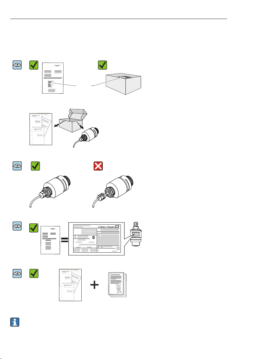
6 Incoming acceptance and product identification
6.1 Incoming acceptance
Are the order codes on the delivery note
A0028673
A0022480
A0029100
A0028673
(1) and the product sticker (2) identical?
Are the goods undamaged?
A0029071
Do the nameplate data match the ordering
information on the delivery note?
A0028673
A0029102
Is the DVD with the operating tool
present?
A0028673
If required (see nameplate): Are the safety
instructions (XA) present?
A0022494
If one of these conditions is not satisfied, contact your Endress+Hauser Sales Center.
10 Endress+Hauser

Micropilot FMR20 HART Incoming acceptance and product identification
6.2 Product identification
The following options are available for identification of the measuring device:
• Nameplate specifications
• Extended order code with breakdown of the device features on the delivery note
• Enter serial numbers from nameplates in W@M Device Viewer
(www.endress.com/deviceviewer): All information about the measuring device and an
overview of the scope of the associated Technical Documentation is displayed.
• Enter the serial number from the nameplates into the Endress+Hauser Operations App, or
scan the 2-D matrix code (QR code) on the nameplate with the
Endress+Hauser Operations App: All information about the measuring device and an
overview of the scope of the associated Technical Documentation is displayed.
Endress+Hauser 11

Incoming acceptance and product identification Micropilot FMR20 HART
12
11
8
7
6
2
1
3
4
5
19
20
18
15 16
13
17
14
24
Ext. ord. cd.:
Order code:
Ser. no.:
T max:
p
DeviceID:
Date:
FW
ex works
Mat.:
:
Dev.Rev.:
10
Ta:
if modification
see sep. label
X =
MWP:
23
21
22
9
2 Nameplate of Micropilot
1 Manufacturer's address
2 Device name
3 Order code
4 Serial number (ser. no.)
5 Extended order code (Ext. ord. cd.)
6 Supply voltage
7 Signal outputs
8 Process pressure
9 Permitted ambient temperature (Ta)
10 Maximum process temperature
11 Device ID
12 Firmware version (FW)
13 Device revision (Dev.Rev.)
14 CE mark
15 Additional information about the device version (certificates, approvals)
16 C-Tick
17 Materials in contact with process
18 Degree of protection: e.g. IP, NEMA
19 Certificate symbol
20 Certificate and approval relevant data
21 Document number of the Safety Instructions: e.g. XA, ZD, ZE
22 Modification mark
23 2-D matrix code (QR code)
24 Manufacturing date: year-month
12 Endress+Hauser
A0029096
Micropilot FMR20 HART Installation
B
C
D
A
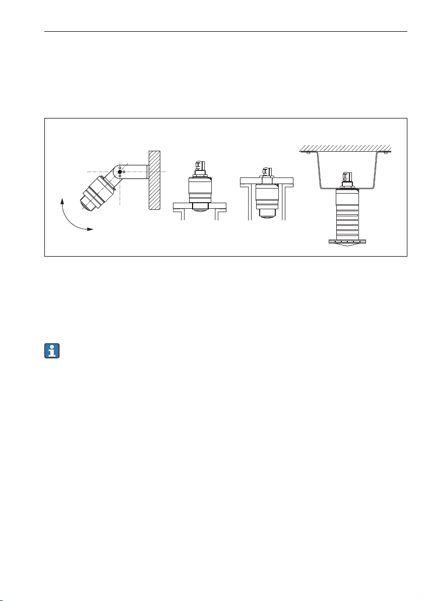
7 Installation
7.1 Installation conditions
7.1.1 Installation types
A0030605
3 Wall, ceiling or nozzle installation
A Wall or ceiling mount, adjustable
B Mounted at front thread
C Mounted at rear thread
D Ceiling installation with counter nut (included in delivery)
Caution!
The sensor cable is not designed as supporting cable. Do not use as a suspension wire.
7.1.2 Nozzle installation
The antenna should be just out of the nozzle for optimum measurement. The interior of the
nozzle must be smooth and may not contain any edges or welded joints. The edge of the
nozzle should be rounded if possible. The maximum nozzle length L depends on the nozzle
diameter D. Please note the specified limits for the diameter and length of the nozzle.
Endress+Hauser 13

Installation Micropilot FMR20 HART
BA
L
D
L
D
L
D
L
D
A0028413
4 FMR20 nozzle installation
A FMR20 80 mm (3 in) antenna
B FMR20 40 mm (1.5 in) antenna
80 mm (3 in) Antenna,
inside nozzle
D min. 120 mm (4.72 in) min. 80 mm (3 in) min. 40 mm (1.5 in) min. 80 mm (3 in)
L max. 205 mm (8.07 in) +
D x 4.5
80 mm (3 in) Antenna,
outside nozzle
max. D x 4.5 max. D x 1.5 max. 140 mm (5.5 in) +
40 mm (1.5 in) Antenna,
outside nozzle
40 mm (1.5 in) Antenna,
inside nozzle
D x 1.5
14 Endress+Hauser

Micropilot FMR20 HART Installation
1
4
1/6D
BD
2 3
D
7.1.3 Orientation
A0028410
5 Tank installation position
• If possible install the sensor so that its lower edge projects into the vessel.
• Do not install the sensor in the middle of the tank (2). We recommend leaving a distance
(1) between the sensor and the tank wall measuring 1/6 of the tank diameter.
Recommended distance A wall - nozzle outer edge: ~ 1/6 of the tank diameter D. However,
the device must not under any circumstances be mounted closer than 15 cm (5.91 in) to the
tank wall.
• Avoid measurements through the filling curtain (3).
• Avoid equipment (4) such as limit switches, temperature sensors, baffles, heating coils etc.
• Multiple devices can be operated in one tank without influencing each other.
• No signals are analyzed within the Blocking distance. It can therefore be used to suppress
interference signals (e.g. the effects of condensate) close to the antenna.
By default an automatic Blocking distance of at least 0.1 m (0.33 ft) is preset. However it
can be manually overwritten (even 0 m (0 ft) is allowed.
Automatic calculation:
Blocking distance = Empty calibration - Full calibration - 0.2 m (0.656 ft).
The Blocking distance parameter is recalculated according to this formula every time a new
value is entered into the Empty calibration parameter or Full calibration parameter.
If this calculation results in a value <0.1 m (0.33 ft), the blocking distance of 0.1 m (0.33 ft)
is used instead.
Endress+Hauser 15
 Loading...