

Page 1
BA00274P/00/EN/18.16
71336359
valid from Software version:
02.30.zz
Products Solutions Services
Description of Instrument Functions
Cerabar S PMC71, PMP71, PMP75
Deltabar S FMD77 / 78, PMD75
Deltapilot S FMB70
Process pressure / Differential pressure, Flow /
Hydrostatic
Page 2
Cerabar S/Deltabar S/Deltapilot S 4...20mA HART
Order code:
Ext. ord. cd.:
Ser. no.:
www.endress.com/deviceviewer
Endress+Hauser
Operations App
XXXXXXXXXXXX
XXXXX-XXXXXX
XXX.XXXX.XX
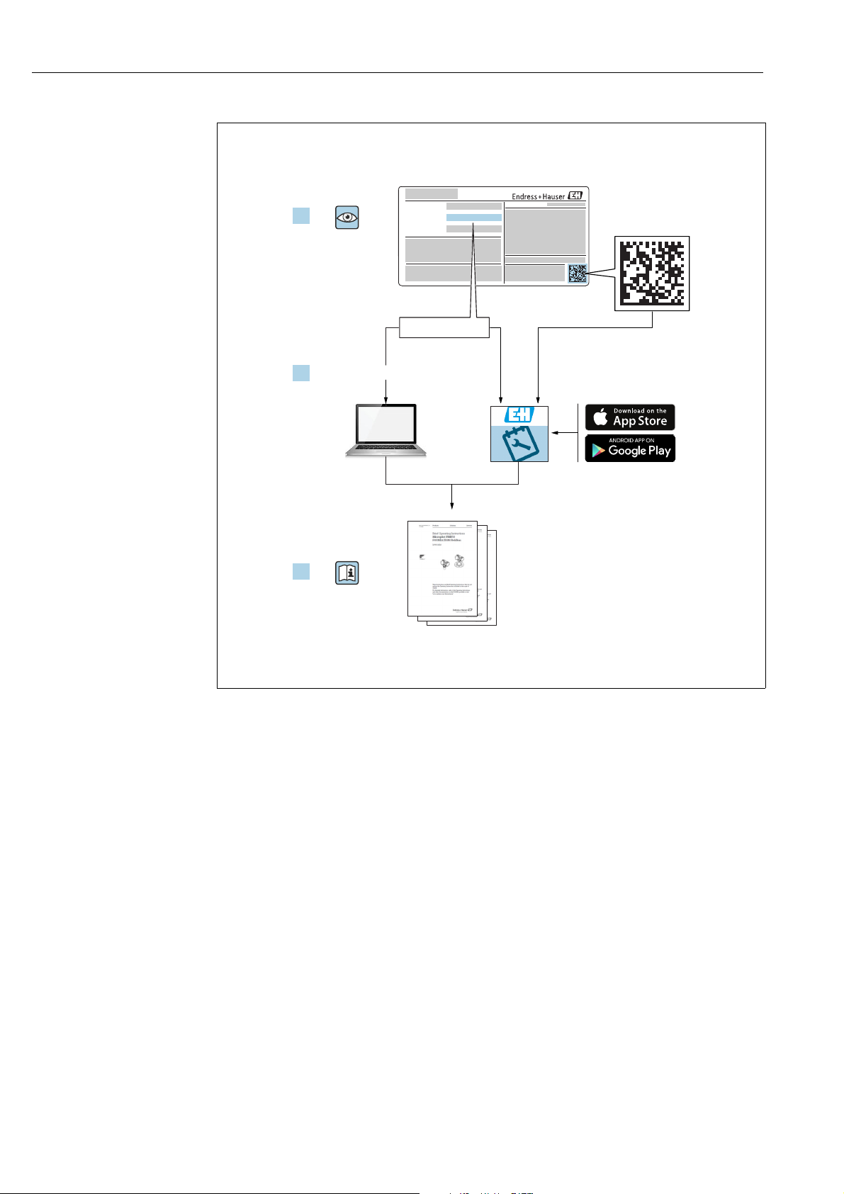
Serial number
1.
3.
2.
A0023555
Make sure the document is stored in a safe place such that it is always available when
working on or with the device.
To avoid danger to individuals or the facility, read the "Basic safety instructions" section
carefully, as well as all other safety instructions in the document that are specific to
working procedures.
The manufacturer reserves the right to modify technical data without prior notice. Your
Endress+Hauser Sales Center will supply you with current information and updates to these
Instructions.
2 Endress+Hauser
Page 3

Cerabar S/Deltabar S/Deltapilot S 4...20mA HART
Table of contents
1 Document information . . . . . . . . . . . . . . 4
1.1 Symbols used . . . . . . . . . . . . . . . . . . . . . . . . . . . . . . . 4
2 Basic safety instructions . . . . . . . . . . . . . 4
3 Notes on use . . . . . . . . . . . . . . . . . . . . . . . 4
4 Pressure measurement . . . . . . . . . . . . . . 5
4.1 Calibration with reference pressure . . . . . . . . . . . . 5
4.2 Calibration without reference pressure . . . . . . . . . 6
5 Level measurement . . . . . . . . . . . . . . . . . 8
5.1 Overview of level measurement . . . . . . . . . . . . . . 8
5.2 "Level Easy Pressure" level selection . . . . . . . . . . . . 9
5.3 "Level Easy Height" level selection . . . . . . . . . . . . 13
5.4 "Level Standard" level selection,
"Linear" level type . . . . . . . . . . . . . . . . . . . . . . . . . 17
5.5 "Level Standard" level selection,
"Pressure Linearized" level type . . . . . . . . . . . . . . 21
5.6 "Level Standard" level selection,
"Height Linearized" level type . . . . . . . . . . . . . . . 26
6 Flow measurement . . . . . . . . . . . . . . . .33
6.1 Calibration . . . . . . . . . . . . . . . . . . . . . . . . . . . . . . . 33
6.2 Totalizers . . . . . . . . . . . . . . . . . . . . . . . . . . . . . . . . 35
7 On-site display operating menu . . . . .36
8 FieldCare operating menu . . . . . . . . . .43
9 Description of parameters . . . . . . . . . .62
10 Troubleshooting. . . . . . . . . . . . . . . . . .131
10.1 Messages . . . . . . . . . . . . . . . . . . . . . . . . . . . . . . . 131
10.2 Response of outputs to errors . . . . . . . . . . . . . . 140
10.3 Confirming messages . . . . . . . . . . . . . . . . . . . . . 141
Index. . . . . . . . . . . . . . . . . . . . . . . . . . . .142
Endress+Hauser 3
Page 4
Document information Cerabar S/Deltabar S/Deltapilot S 4...20mA HART
DANGER
WARNING
CAUTION
NOTICE
1 Document information
1.1 Symbols used
1.1.1 Safety symbols
Symbol Meaning
DANGER!
A0011189-DE
A0011190-DE
A0011191-DE
A0011192-DE
This symbol alerts you to a dangerous situation. Failure to avoid this situation will result in
seriousor fatal injury.
WARNING!
This symbol alerts you to a dangerous situation. Failure to avoid this situation can result in
seriousor fatal injury.
CAUTION!
This symbol alerts you to a dangerous situation. Failure to avoid this situation can result in
minoror medium injury.
NOTICE!
This symbol contains information on procedures and other facts which do not result in
personalinjury.
1.1.2 Symbols for certain types of information
Symbol Meaning
Tip
Indicates additional information.
A0011193
2 Basic safety instructions
Siehe Betriebsanleitung:
Deltabar S BA00270P
Cerabar S BA00271P
Deltapilot S BA00332P
3 Notes on use
Typical examples of configuration see chapter 4 to 6
Operating menu of the on-site display see Chapter 7
FieldCare operating menu see Chapter 8
Parameter description see Chapter 9
Finding parameter description using parameter names (index) see Page 142
4 Endress+Hauser
Page 5

Cerabar S/Deltabar S/Deltapilot S 4...20mA HART Pressure measurement
WARNING
!
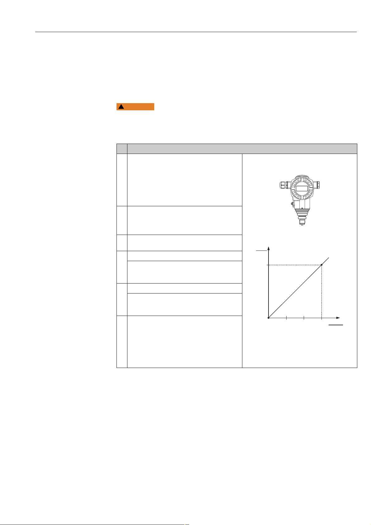
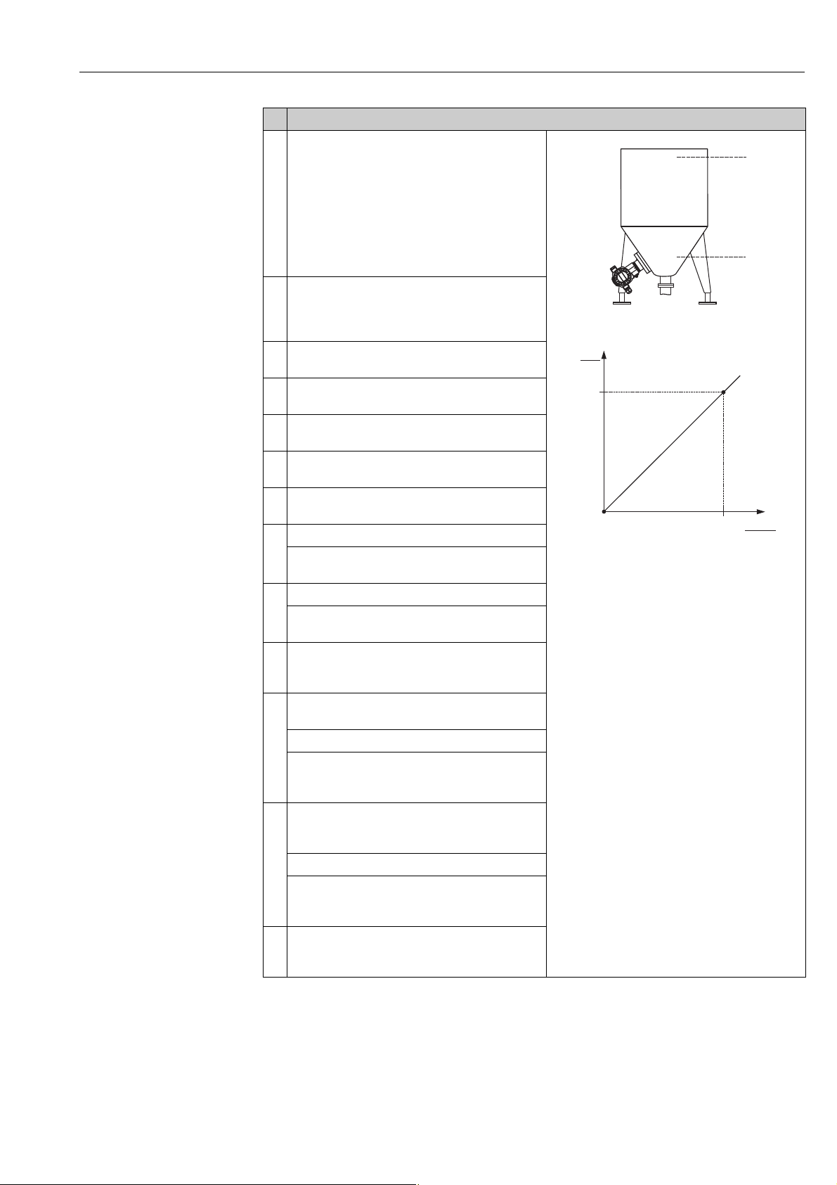
4 Pressure measurement
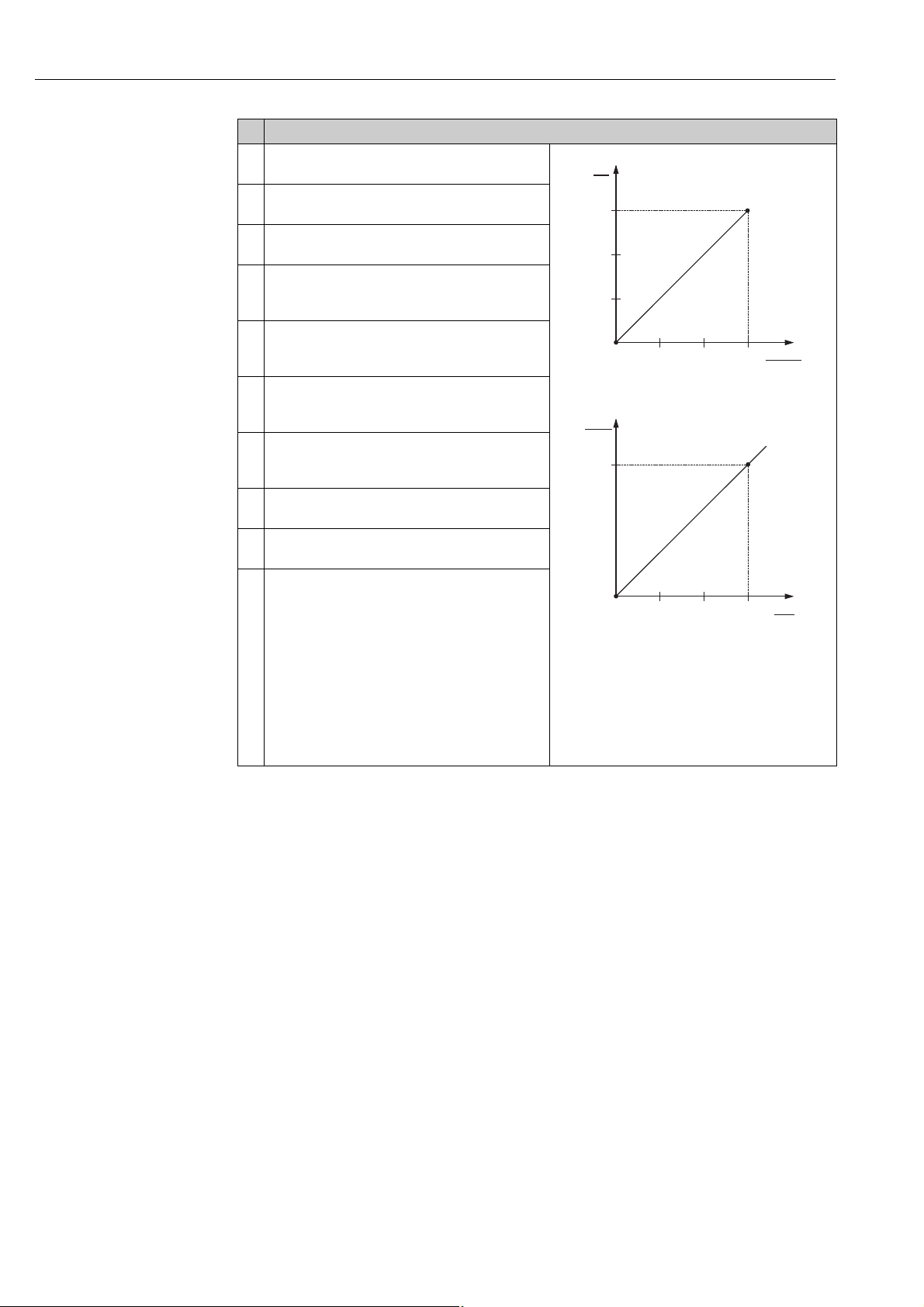
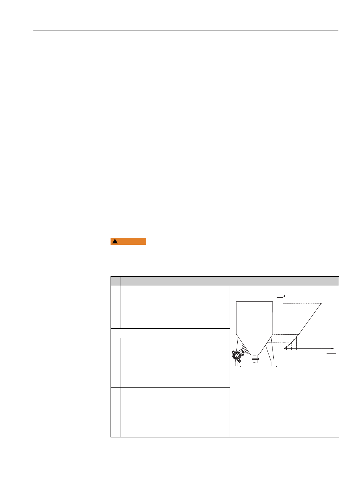
4.1 Calibration with reference pressure
Example:
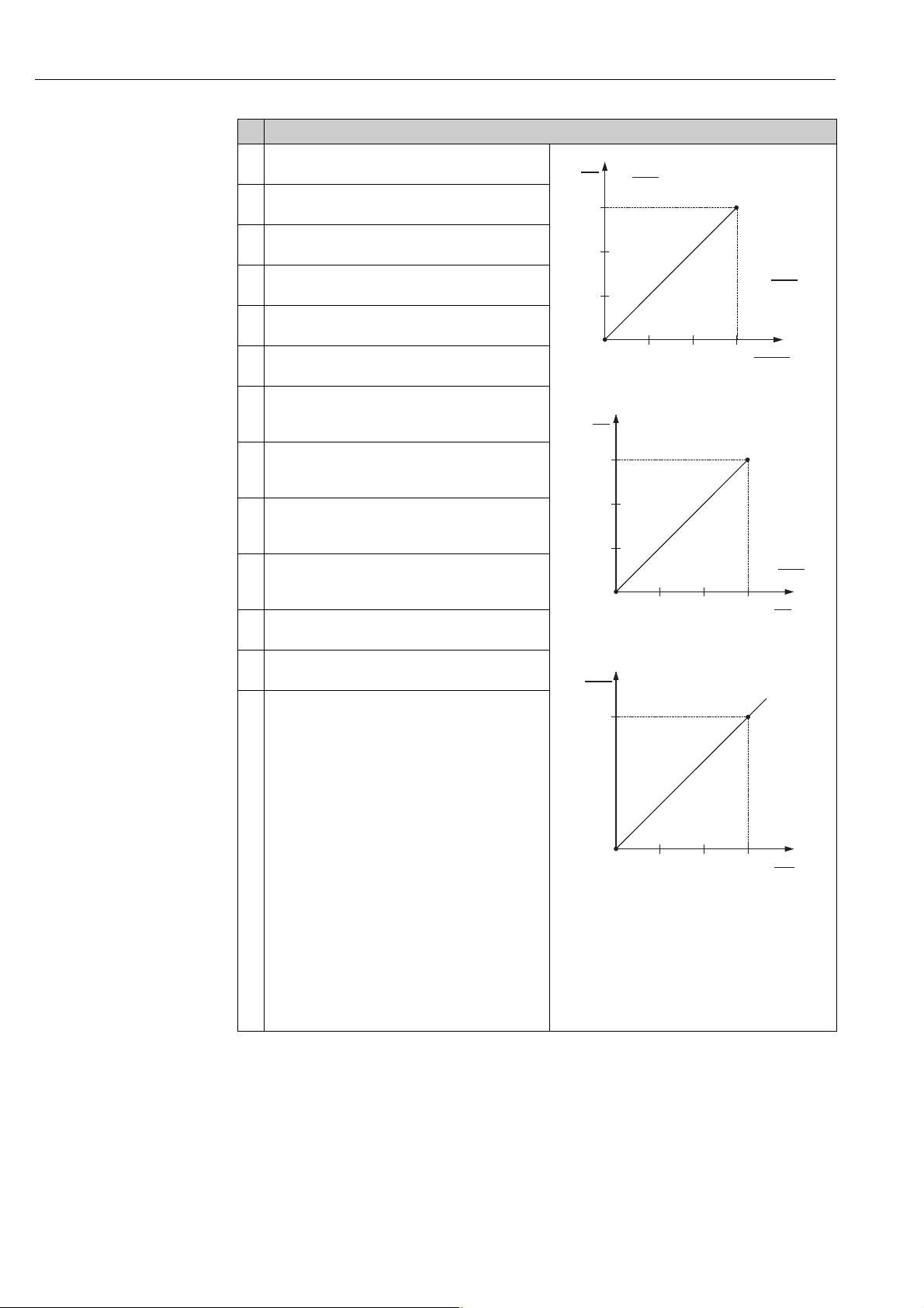
In this example, a device with a 500 mbar (7.5 psi) sensor is configured for the 0...+300
mbar (4.5 psi)measuring range, i.e. 0 mbar and 300 mbar (4.5 psi) are assigned to the 4 mA
value and 20 mA value respectively.
Prerequisite:
• The pressure values 0 mbar and 300 mbar (4.5 psi) can be specified. The device is already
installed, for example.
• See also Operating Instructions Deltabar S (BA00270P), Section "Differential pressure
measurement", Cerabar S (BA00271P), Section "Pressure measurement" or Deltapilot S
(BA00332P), Section "Pressure measurement".
• For a description of the parameters mentioned, see
– Page 62, Table 2: MEASURING MODE
– Page 68, Table 6: POSITION ADJUSTMENT
– Page 69, Table 7: BASIC SETUP.
• For a description of further relevant parameters, see
– Page 100, Table 15: EXTENDED SETUP
– Page 120, Table 25: PROCESS VALUES.
Changing the measuring mode can affect the adjustment data!
This situation can result in product overflow.
‣ Check calibration data when the measuring mode is changed.
Endress+Hauser 5
Page 6
Pressure measurement Cerabar S/Deltabar S/Deltapilot S 4...20mA HART
+
–
20
4
I
[mA]
0 300
p
[mbar]
➀
➁
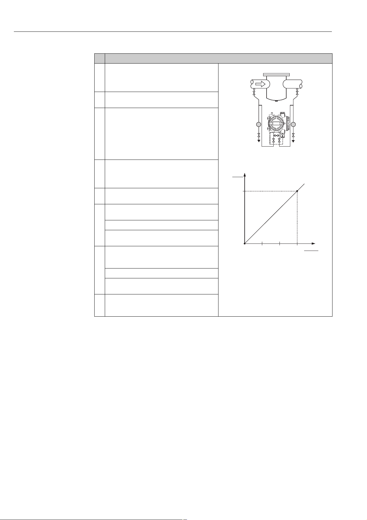
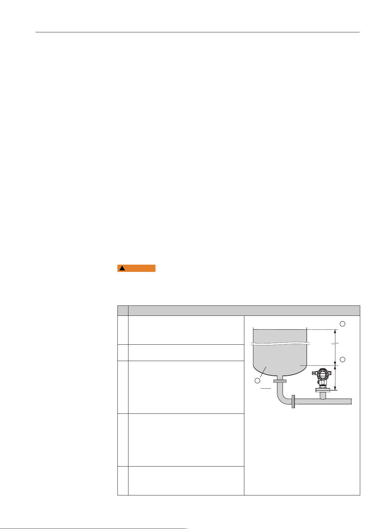
Description
1 Deltabar S: before configuring the device for your
application, the pressure piping must be cleaned and
filled with fluid. See Operating Instructions
BA00270P.
2 Carry out position adjustment if necessary. See Page
68, Table 6: POSITION ADJUSTMENT.
3 If necessary, select the "Pressure" measuring mode
via the MEASURING MODE parameter.
On-site display:
Menu path: GROUP SELECTION MEASURING
MODE
Digital communication:
See Page 62
4On-site display:
Select BASIC SETUP function group.
Menu path: GROUP SELECTION OPERATING
MENU SETTINGS BASIC SETUP
5 Select a pressure unit via the PRESS. ENG. UNIT
parameter, here mbar for example.
6 The pressure for the lower range value (4 mA value)
is present at the device, here 0 mbar for example.
Select GET LRV parameter.
Confirm value present. The pressure value present is
assigned to the lower current value (4 mA).
7 The pressure for the upper range value (20 mA
value) is present at the device, here 300 mbar (4.5
psi) for example.
Select GET URV parameter.
Confirm value present. The pressure value present is
assigned to the upper current value (20 mA).
8Result:
The measuring range is set for 0...+300 mbar (4.5
psi).
Fig. 1: Calibration with reference pressure
1 See table, step 6.
2 See table, step 7.
P01-PMD75xxx-19-xx-xx-xx-000
P01-xxxxxxxx-05-xx-xx-xx-010
You can also specify a customer-specific unit. See parameter description for PRESS. ENG.
UNIT (Page 69).
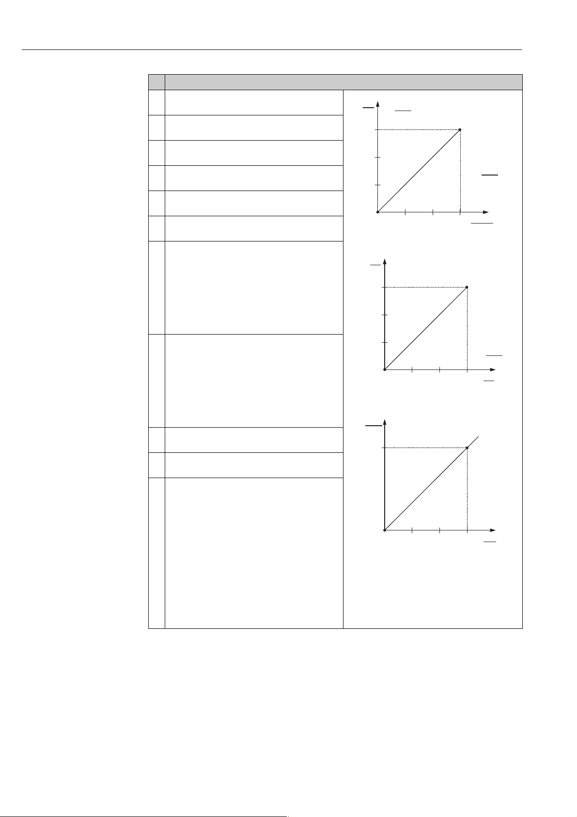
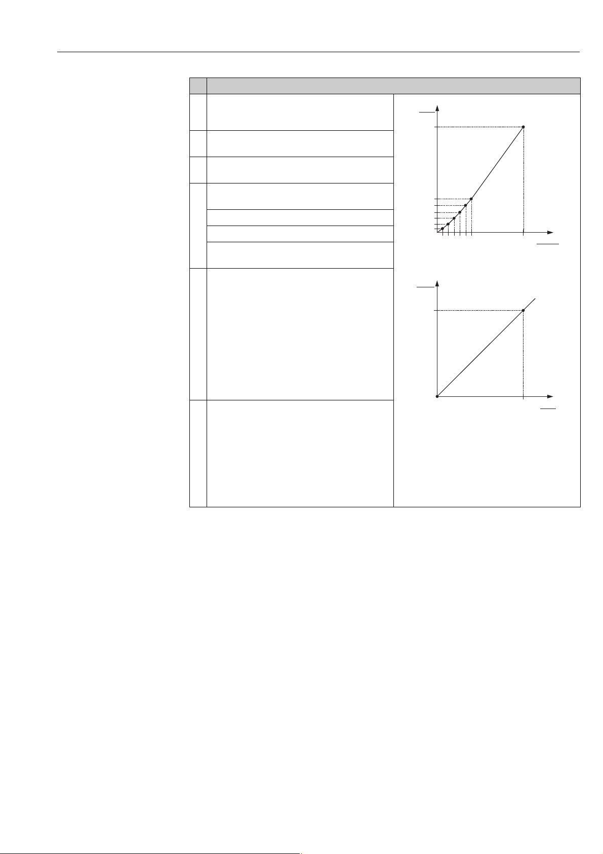
4.2 Calibration without reference pressure
Example:
In this example, a device with a 400 mbar (6 psi) sensor is configured for the 0...+300 mbar
(4.5 psi) measuring range, i.e. 0 mbar and 300 mbar (4.5 psi) are assigned to the 4 mA value
and 20 mA value respectively.
Prerequisite:
• This is a theoretical calibration, i.e. the pressure values for the lower range and upper
6 Endress+Hauser
range value are known.
• See also Operating Instructions Deltabar S (BA00270P), Section "Differential pressure
measurement", Cerabar S (BA00271P), Section "Pressure measurement" or Deltapilot S
(BA00332P), Section "Pressure measurement".
• Due to the orientation of the device, there may be a shift in the measured value, i.e. when
the container is empty, the MEASURED VALUE parameter does not display zero. To
perform a position adjustment see also Page 68, Table 6: Position adjustment.
Page 7
Cerabar S/Deltabar S/Deltapilot S 4...20mA HART Pressure measurement
WARNING
!
20
4
I
[mA]
0 300
p
[mbar]
➀
➁
• For a description of the parameters mentioned, see
– Page 62, Table 2: MEASURING MODE
– Page 68, Table 6: POSITION ADJUSTMENT
– Page 69, Table 7: BASIC SETUP.
• For a description of further relevant parameters, see
– Page 100, Table 15: EXTENDED SETUP
– Page 120, Table 27: PROCESS VALUES.
Changing the measuring mode can affect the adjustment data!
This situation can result in product overflow.
‣ Check calibration data when the measuring mode is changed.
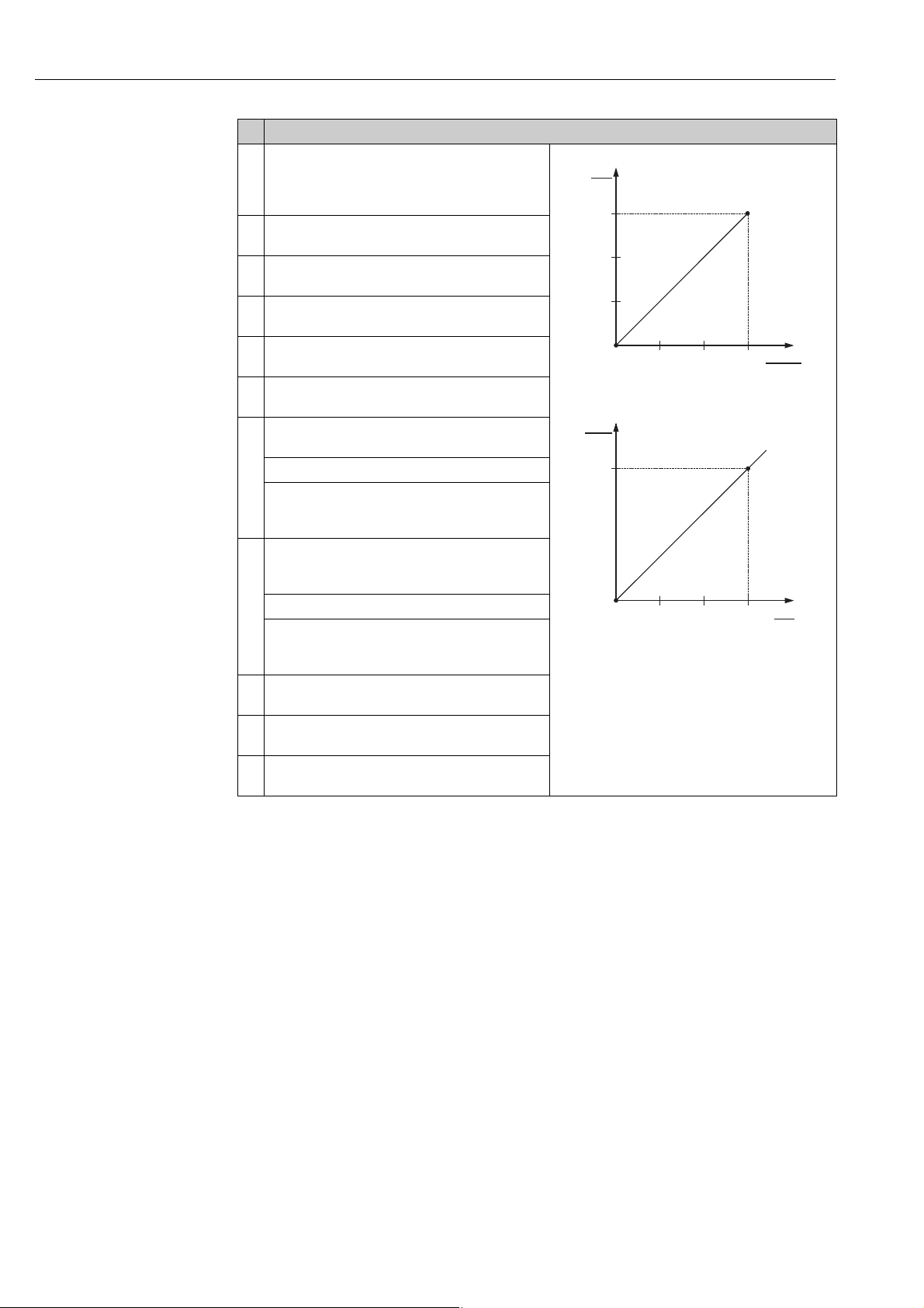
Description
1 If necessary, select the "Pressure" measuring mode
via the MEASURING MODE parameter.
On-site display:
Menu path: GROUP SELECTION MEASURING
MODE
Digital communication:
See Page 62
2 On-site display:
Select BASIC SETUP function group.
Menu path: GROUP SELECTION OPERATING
MENU SETTINGS BASIC SETUP
3 Select a pressure unit via the PRESS. ENG. UNIT
parameter, here mbar for example.
4 Select SET LRV parameter.
Enter value, here 0 mbar, for the SET LRV parameter
and confirm. This pressure value is assigned to the
lower current value (4 mA).
5 Select SET URV parameter.
Enter value, here 300 mbar (4.5 psi), for the SET
URV parameter and confirm. This pressure value is
assigned to the upper current value (20 mA).
6 Result:
The measuring range is set for 0...+300 mbar (4.5
psi).
Fig. 2: Calibration without reference pressure
1 See table, step 4.
2 See table, step 5.
P01-PMP71xxx-19-xx-xx-xx-000
P01-xxxxxxxx-05-xx-xx-xx-010
Endress+Hauser 7
• You can also perform calibration without reference pressure by means of the QUICK SETUP
menu. See Page 64 ff, Table 3: QUICK SETUP menu.
• You can also specify a customer-specific unit. See parameter description for PRESS. ENG.
UNIT (Page 69).
Page 8
Level measurement Cerabar S/Deltabar S/Deltapilot S 4...20mA HART
5 Level measurement
5.1 Overview of level measurement
Measuring task LEVEL SELECTION/
The measured variable is in
direct proportion to the
measured pressure.
Calibration is performed by
entering two pressure-level
value pairs.
The measured variable is in
direct proportion to the
measured pressure.
Calibration is performed by
entering the density and
two height-level value
pairs.
The measured variable is in
direct proportion to the
measured pressure.
The measured variable is
not in direct proportion to
the measured pressure as,
for example, with
containers with a conical
outlet. A
linearisation table must be
entered for the calibration.
– Two measured variables
are required or
– The container shape is
given by value pairs, such
as height and volume.
The 1st measured variable
%-height or height must be
in direct proportion to the
measured pressure. The
2nd measured variable
volume, mass or % must
not be in direct proportion
to the measured pressure.
A linearisation table must
be entered for the 2nd
measured variable. The 2nd
measured variable is
assigned to the 1st
measured variable by
means of this table.
LEVEL MODE
LEVEL SELECTION:
Level Easy Pressure
LEVEL SELECTION:
Level Easy Height
LEVEL SELECTION:
Level standard/
LEVEL MODE:
Linear
LEVEL SELECTION:
Level standard/
LEVEL MODE:
Pressure Linearized
LEVEL SELECTION:
Level standard/
LEVEL MODE:
Height Linearized
Measured
variable options
Via OUTPUT UNIT
parameter: %, level,
volume or mass
units.
Via OUTPUT UNIT
parameter: %, level,
volume or mass
units.
Via LIN.
MEASURAND
parameter:
–% (Level)
– Level
–Volume
–Mass
Via LINd
MEASURAND
parameter:
– Pressure + %
– Pressure +
Volume
– Pressure + Mass
Via COMB.
MEASURAND
parameter:
–Height + Volume
–Height + Mass
–Height + %
–%-Height +
Volume
–%-Height + Mass
–%-Height + %
Description Comment Measured value
–Calibration with
reference pressure –
wet calibration, see
Page 9, Section 5.2.1
– Calibration without
reference pressure –
dry calibration, see
Page 11, Section 5.2.2
–Calibration with
reference pressure –
wet calibration, see
Page 13, Section 5.3.1
– Calibration without
reference pressure –
dry calibration, see
Page 15, Section 5.3.2
–Calibration with
reference pressure –
wet calibration, see
Page 17, Section 5.4.1
– Calibration without
reference pressure –
dry calibration, see
Page 19, Section 5.4.2
–Calibration with
reference pressure:
semiautomatic entry
of linearisation table,
see Page 21, Section
5.5.1
– Calibration without
reference pressure:
manual entry of
linearisation table, see
Page 24, Section 5.5.2
–Calibration with
reference pressure:
wet calibration and
semiautomatic entry
of linearisation table,
see Page 26, Section
5.6.1
– Calibration without
reference pressure:
dry calibration and
manual entry of
linearisation table, see
Page 30, Section 5.6.2
– Incorrect entries are
possible
– SIL mode possible
– Customised units are
not possible
– Incorrect entries are
possible
– SIL mode not possible
– Customised units are
not possible
– Incorrect entries are
rejected by the device
– SIL mode not possible
– Customised level,
volume and mass
units are possible
– Incorrect entries are
rejected by the device
– SIL mode not possible
– Customised level,
volume and mass
units are possible
– Incorrect entries are
rejected by the device
– SIL mode not possible
– Customised level,
volume and mass
units are possible
display
The measured value
display and the LEVEL
BEFORE LIN parameter
show the measured
value.
The measured value
display and the LEVEL
BEFORE LIN parameter
show the measured
value.
The measured value
display and the LEVEL
BEFORE LIN parameter
show the measured
value.
The measured value
display and the TANK
CONTENT parameter
show the measured
value.
The measured value
display and the TANK
CONTENT parameter
show the 2nd
measured value
(volume, mass or %).
The LEVEL BEFORE
LIN parameter displays
the 1st measured value
(%-height or height).
8 Endress+Hauser
Page 9
Cerabar S/Deltabar S/Deltapilot S 4...20mA HART Level measurement
WARNING
!
➀
➁
0 mbar
300 mbar
3 m
0 m
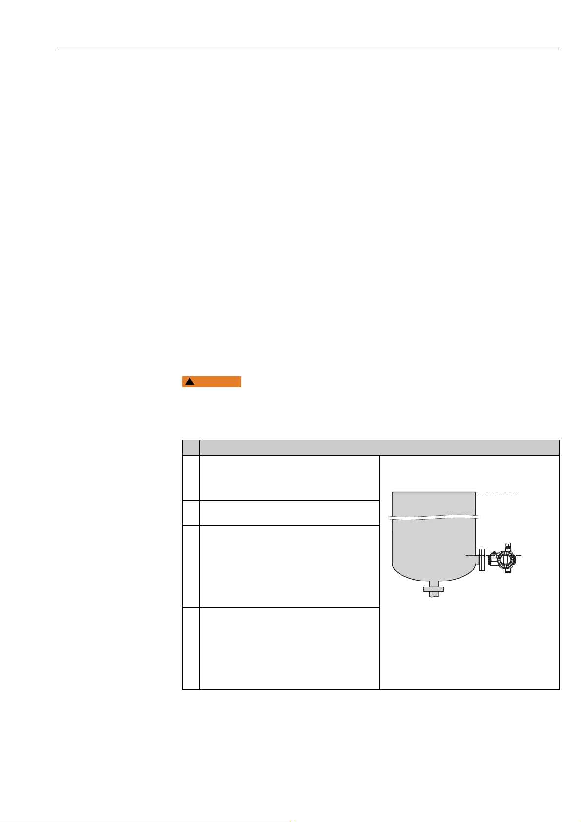
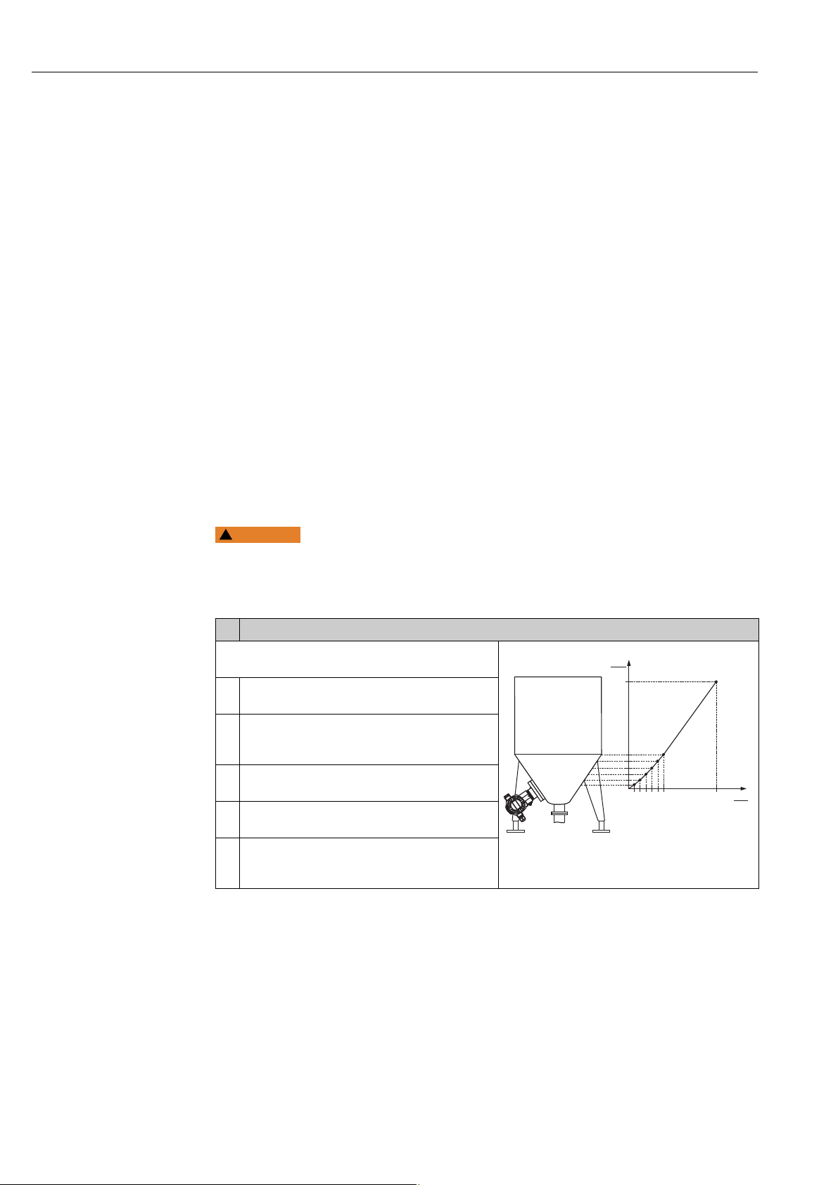
5.2 "Level Easy Pressure" level selection
5.2.1 Calibration with reference pressure – wet calibration
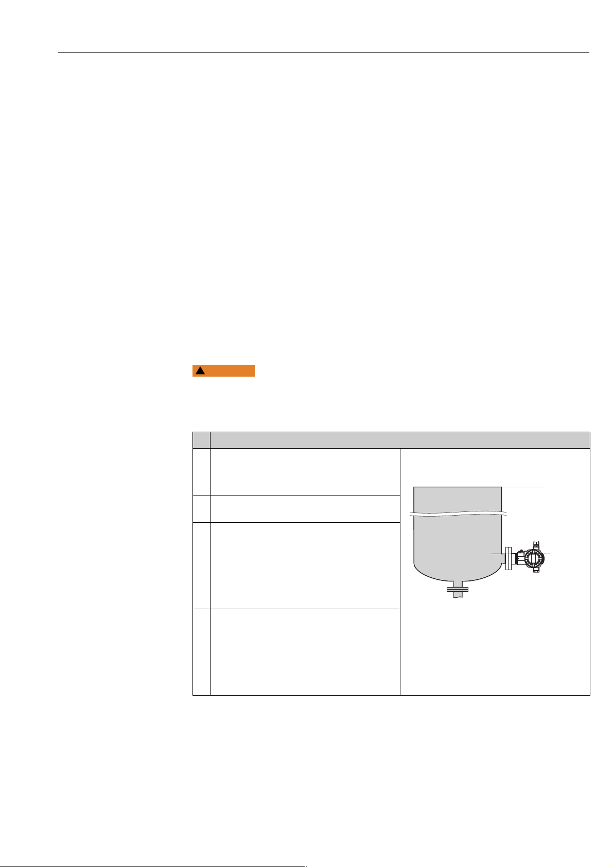
Example:
In this example, the level in a tank should be measured in m. The maximum level is 3 m (9.8
ft). The pressure range is set to 0 to 300 mbar (4.5 psi).
Prerequisite:
• The measured variable is in direct proportion to the pressure.
• The tank can be filled or emptied.
• See also Operating Instructions for Deltabar S (BA00270P) or Cerabar S (BA00271P),
Section "Level measurement" or Deltapilot S (BA00332P), Section "Level measurement".
• The values entered for EMPTY CALIB./FULL CALIB. and SET LRV/SET URV must have a
minimum interval of 1% for the "Level Easy Pressure" level mode. The value will be rejected
with a warning message if the values are too close together. Further limit values are not
checked; i.e. the values entered must be appropriate for the sensor and the measuring task
so that the measuring device can measure correctly.
• For a description of the parameters mentioned, see
– Page 62, Table 2: MEASURING MODE
– Page 68, Table 6: POSITION ADJUSTMENT
– Page 70, Table 8: LEVEL SELECTION "Level Easy Pressure"
• For a description of further relevant parameters, see
– Page 100, Table 16: EXTENDED SETUP
– Page 121, Table 28: PROCESS VALUES.
Changing the measuring mode can affect the adjustment data!
This situation can result in product overflow.
‣ Check calibration data when the measuring mode is changed.
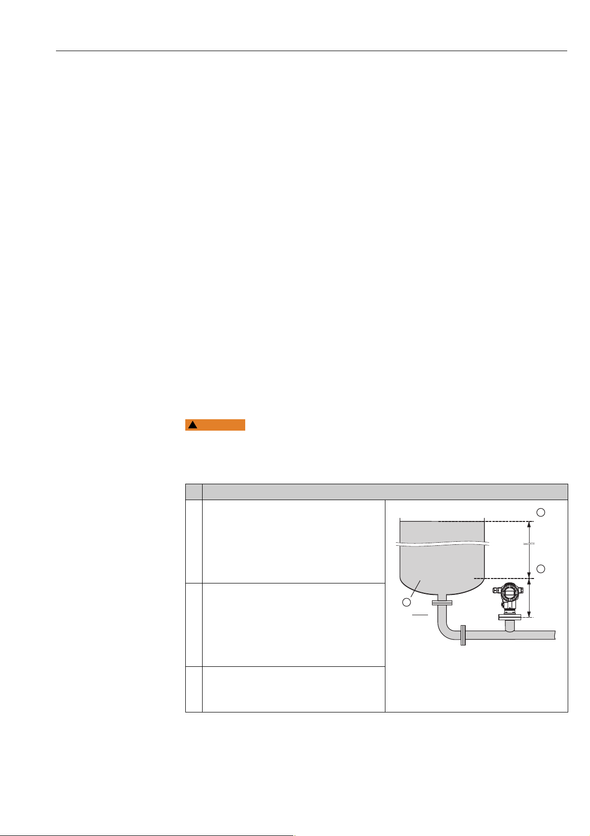
Description
1 Deltabar S: Before you configure the device for your
application, the pressure piping must be cleaned and
filled with medium. See Operating Instructions
BA00270P.
2 Carry out position adjustment if necessary. See Page
68, Table 6: POSITION ADJUSTMENT.
3 If necessary, select the "Level" measuring mode via
the MEASURING MODE parameter.
On-site display:
Menu path: GROUP SELECTION MEASURING
MODE
Digital communication:
See Page 62
4 If necessary, select "Level Easy Pressure" level mode
using the LEVEL SELECTION parameter.
On-site display:
Menu path: GROUP SELECTION MEASURING
MODE "Level" LEVEL SELECTION
Digital communication:
See Page 63
Fig. 3: Calibration with reference pressure –
wet calibration
1 See Table, Step 9.
2 See Table, Step 10.
P01-PMP75xxx-19-xx-xx-xx-008
Endress+Hauser 9
Page 10

Level measurement Cerabar S/Deltabar S/Deltapilot S 4...20mA HART
3
0
h
[m]
0 300
p
[mbar]
➀
➁
20
4
I
[mA]
0
3
h
[m]
➂
➃
Description
5On-site display:
Select BASIC SETUP function group. Menu path:
GROUP SELECTION OPERATING MENU
SETTINGS BASIC SETUP
6 Select a pressure unit via the PRESS. ENG. UNIT
parameter, here mbar for example.
7 Select a level unit via the OUTPUT UNIT parameter,
here m for example.
8 Select the "Wet" option by means of the
CALIBRATION MODE parameter.
9 Hydrostatic pressure for the lower calibration point
is present at the device, here 0 mbar for example.
Select EMPTY CALIB. parameter.
Enter the level value, here 0 m for example. Confirm
the value to assign the pressure value present to the
lower level value.
To accept the value displayed you must first switch
to the Edit mode (see the "Editing values" section)
and then press the button to save the value.
10 Hydrostatic pressure for the upper calibration point
is present at the device, here 300 mbar (4.5 psi) for
example.
Select FULL CALIB. parameter.
Enter the level value, here 3 m (9.8 ft) for example.
Confirm the value to assign the pressure value
present to the upper level value.
To accept the value displayed you must first switch
to the Edit mode (see the "Editing values" section)
and then press the button to save the value.
11 Set the value for the lower current value (4 mA) by
means of the SET LRV parameter.
12 Set the value for the upper current value (20 mA) by
means of the SET URV parameter.
13 Result:
The measuring range is set for 0 to 3 m (9.8 ft).
Fig. 4: Calibration with reference pressure –
1 See Table, Step 9.
2 See Table, Step 10.
3 See Table, Step 11.
4 See Table, Step 12.
wet calibration
P01-xxxxxxxx-05-xx-xx-xx-011
P01-xxxxxxxx-05-xx-xx-xx-014
1. You can also perform calibration with reference pressure by means of the QUICK SETUP
menu. See Page 65 ff, Table 4: QUICK SETUP menu.
2. For this level mode, the measured variables %, level, volume and mass are available.
See also parameter description for OUTPUT UNIT, Page 71.
3. For operation using the on-site display, the parameters EMPTY CALIB. (Page 72) and
FULL CALIB. (Page 73) also show the respective pressure present at the device. For
operation using Digital communication, the pressure present at the device is displayed
in the PROCESS VALUES group (menu path: OPERATING MENUPROCESSINFO
PROCESS VALUES).
10 Endress+Hauser
Page 11
Cerabar S/Deltabar S/Deltapilot S 4...20mA HART Level measurement
WARNING
!
1000 l
50 mbar
450 mba
0 l
ρ = 1
kg
dm
3
1
2
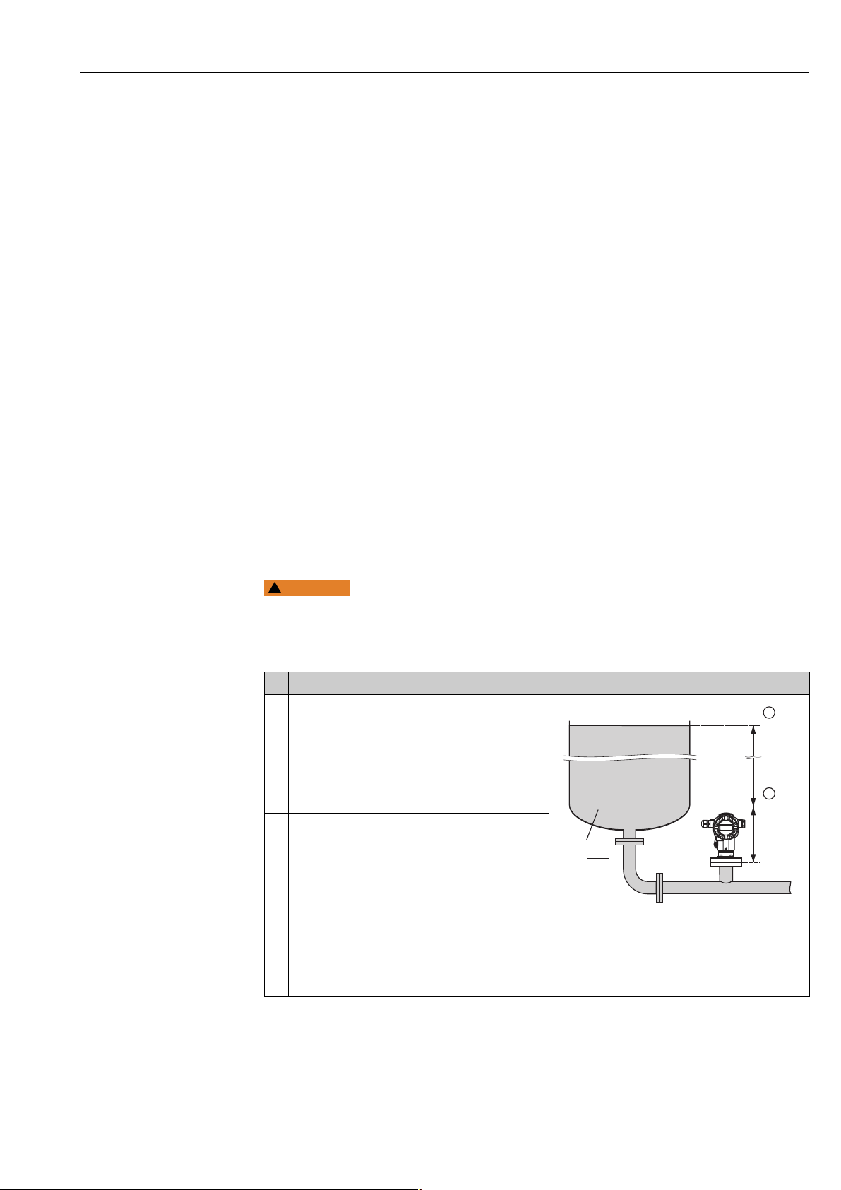
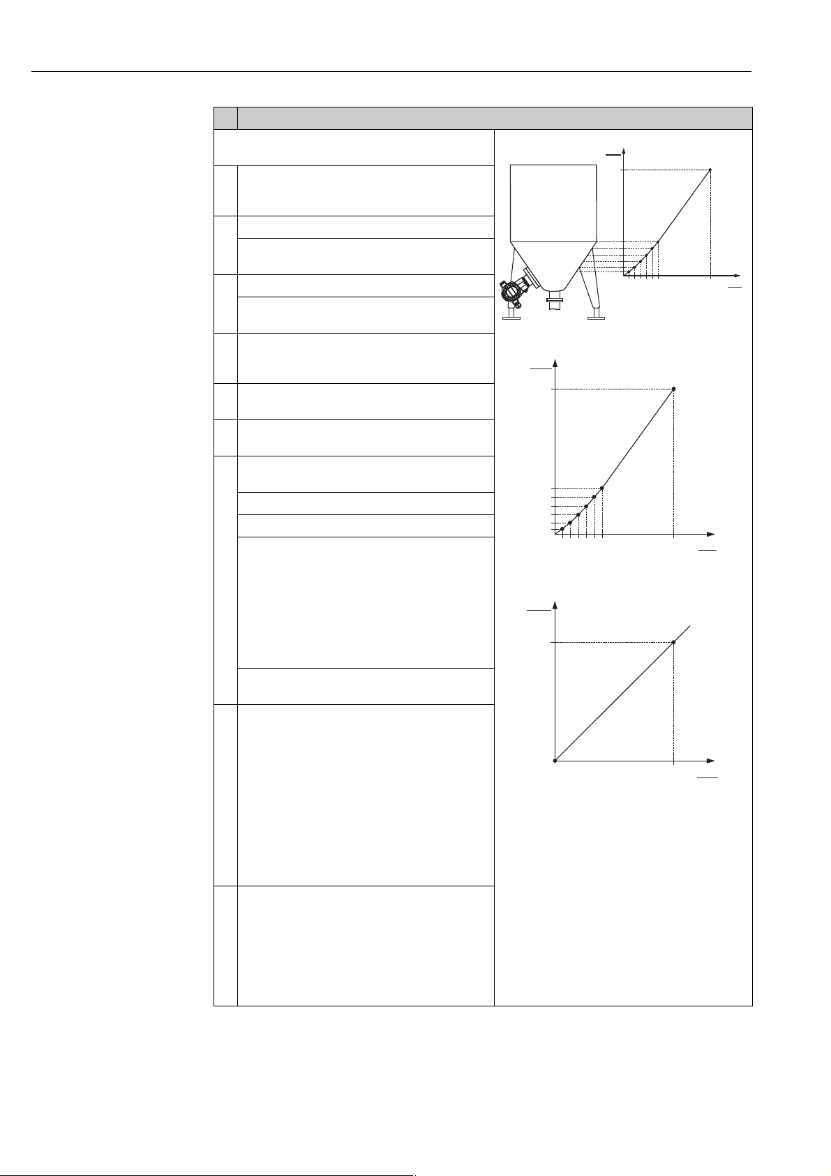
5.2.2 Calibration without reference pressure – dry calibration
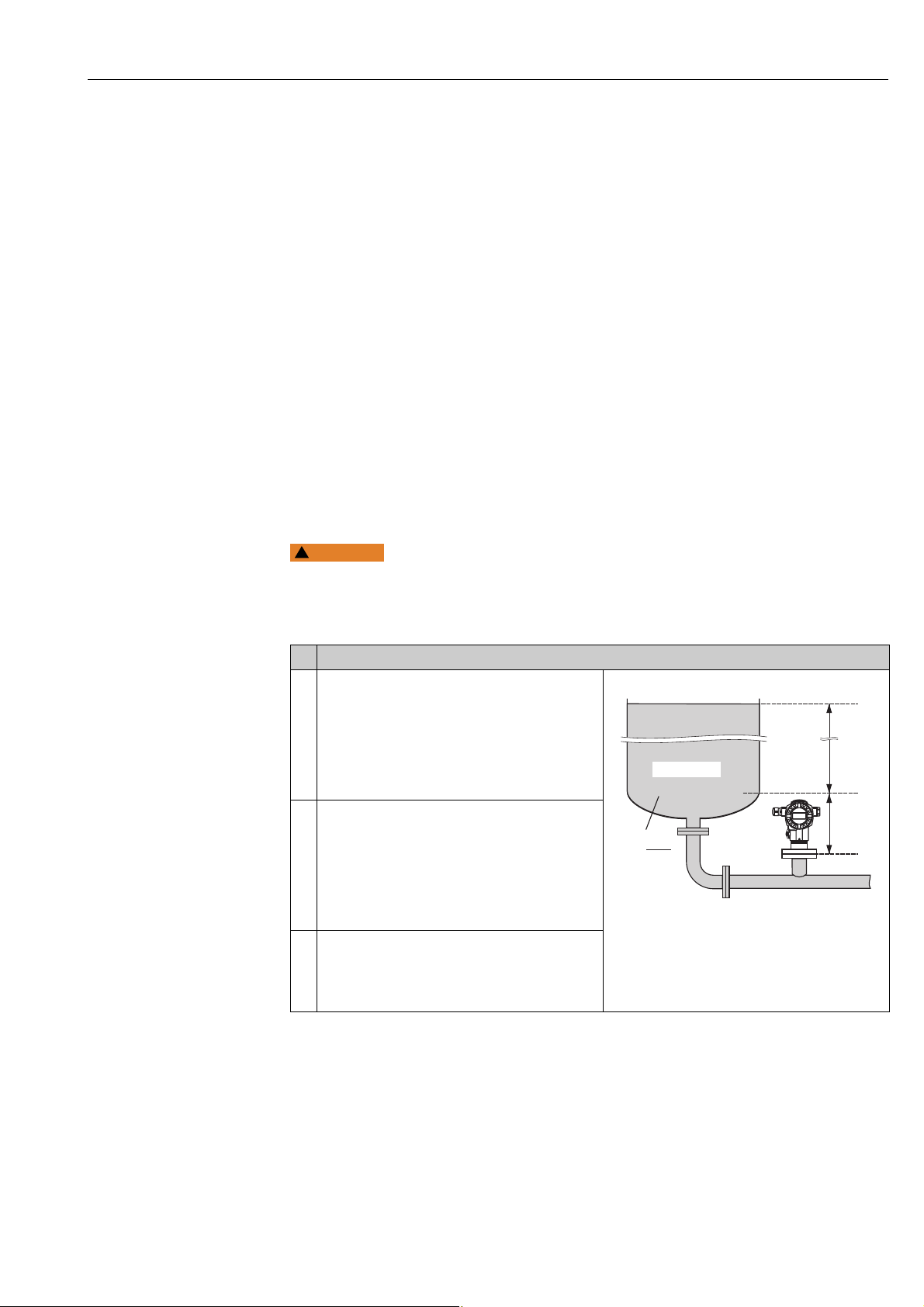
Example:
In this example, the volume in a tank should be measured in litres.The maximum volume of
1000 litres (264 US gal) corresponds to a pressure of 450 mbar (6.75 psi). The minimum
volume of 0 litres corresponds to a pressure of 50 mbar (0.75 psi), as the device is mounted
below the level lower range value. The device is mounted below the level lower range value.
Prerequisite:
• The measured variable is in direct proportion to the pressure.
• This is a theoretical calibration i.e. the pressure and volume values for the lower and upper
calibration point must be known.
• See also Operating Instructions for Deltabar S (BA00270P) or Cerabar S (BA00271P),
Section "Level measurement" or Deltapilot S (BA00332P), Section "Level measurement".
• The values entered for EMPTY CALIB./FULL CALIB. and SET LRV/SET URV must have a
minimum interval of 1% for the "Level Easy Pressure" level mode. The value will be rejected
with a warning message if the values are too close together. Further limit values are not
checked; i.e. the values entered must be appropriate for the sensor and the measuring task
so that the measuring device can measure correctly.
• Due to the orientation of the device, there may be a shift in the measured value, i.e. when
the container is empty, the MEASURED VALUE parameter does not display zero. To
perform a position adjustment see also Page 68, Table 6: Position adjustment.
• For a description of the parameters mentioned, see
– Page 62, Table 2: MEASURING MODE
– Page 70, Table 8: LEVEL SELECTION "Level Easy Pressure"
• For a description of further relevant parameters, see
– Page 100, Table 16: EXTENDED SETUP
– Page 121, Table 28: PROCESS VALUES.
Changing the measuring mode can affect the adjustment data!
This situation can result in product overflow.
‣ Check calibration data when the measuring mode is changed.
Description
1 Select the "Level" measuring mode via the
MEASURING MODE parameter.
On-site display:
Menu path: GROUP SELECTION MEASURING
MODE
Digital communication:
See Page 62
2 If necessary, select "Level Easy Pressure" level mode
using the LEVEL SELECTION parameter.
On-site display:
Menu path: GROUP SELECTION MEASURING
MODE "Level" LEVEL SELECTION
Digital communication:
See Page 63
3 On-site display:
Select BASIC SETUP function group. Menu path:
GROUP SELECTION OPERATING MENU
SETTINGS BASIC SETUP
Fig. 5: Calibration without reference pressure –
1 See Table, Steps 7 and 8.
2 See Table, Steps 9 and 10.
dry calibration
P01-PMC71xxx-19-xx-xx-xx-000
Endress+Hauser 11
Page 12
Level measurement Cerabar S/Deltabar S/Deltapilot S 4...20mA HART
1000
0
V
[l]
50 450
p
[mbar]
➀
➁
➂
➃
20
4
I
[mA]
0 1000
V
[l]
➄
➅
Description
4 Select a pressure unit via the PRESS. ENG. UNIT
parameter, here mbar for example.
5 Select a volume unit via the OUTPUT UNIT
parameter, here l (litres) for example..
6 Select the "Dry" option by means of the
CALIBRATION MODE parameter.
7 Enter the volume value for the lower calibration
point via the EMPTY CALIB. parameter, here 0 l for
example.
8 Enter the pressure value for the lower calibration
point via the EMPTY PRESSURE parameter, here 50
mbar (0.75 psi) for example.
9 Enter the volume value for the upper calibration
point via the FULL CALIB. parameter, here 1000 l
(264 gal) for example.
10 Enter the pressure value for the upper calibration
point via the FULL PRESSURE parameter, here 450
mbar (6.75 psi) for example.
11 Set the value for the lower current value (4 mA) by
means of the SET LRV parameter.
12 Set the value for the upper current value (20 mA) by
means of the SET URV parameter.
13 Result:
The measuring range is set for 0 to 1000 l (264 gal).
P01-xxxxxxxx-05-xx-xx-xx-026
P01-xxxxxxxx-05-xx-xx-xx-028
Fig. 6: Calibration with reference pressure –
1 See Table, Step 7.
2 See Table, Step 8.
3 See Table, Step 9.
4 See Table, Step 10.
5 See Table, Step 11.
6 See Table, Step 12.
wet calibration
For this level mode, the measured variables %, level, volume and mass are available. See
also parameter description for OUTPUT UNIT, Page 71.
12 Endress+Hauser
Page 13
Cerabar S/Deltabar S/Deltapilot S 4...20mA HART Level measurement
WARNING
!
1000 l
0,5 m
4,5 m
0 l
ρ = 1
kg
dm
3
1
3
2
5.3 "Level Easy Height" level selection
5.3.1 Calibration with reference pressure – wet calibration
Example:
In this example, the volume in a tank should be measured in litres. The maximum volume of
1000 litres (264 US gal) corresponds to a level of 4.5 m (15 ft). The minimum volume of 0
litres corresponds to a level of 0.5 m (1.6 ft), as the device is mounted below the level lower
range value. The density of the medium is 1 kg/dm
Prerequisite:
• The measured variable is in direct proportion to the pressure.
• The tank can be filled or emptied.
• See also Operating Instructions for Deltabar S (BA00270P) or Cerabar S (BA00271P),
Section "Level measurement" or Deltapilot S (BA00332P), Section "Level measurement".
• The values entered for EMPTY CALIB./FULL CALIB., EMPTY PRESSURE/FULL PRESSURE,
EMPTY HEIGHT/FULL HEIGHT and SET LRV/SET URV must have a minimum interval of
1% for the "Level Easy Height" level mode. The value will be rejected with a warning
message if the values are too close together. Further limit values are not checked; i.e. the
values entered must be appropriate for the sensor and the measuring task so that the
measuring device can measure correctly.
• For a description of the parameters mentioned, see
– Page 62, Table 2: MEASURING MODE
– Page 68, Table 6: POSITION ADJUSTMENT
– Page 73, Table 9: LEVEL SELECTION "Level Easy Height"
• For a description of further relevant parameters, see
– Page 100, Table 16: EXTENDED SETUP
– Page 121, Table 28: PROCESS VALUES.
3
.
Changing the measuring mode can affect the adjustment data!
This situation can result in product overflow.
‣ Check calibration data when the measuring mode is changed.
Description
1 Deltabar S: Before you configure the device for your
application, the pressure piping must be cleaned and
filled with medium. See Operating Instructions
BA00270P.
2 Carry out position adjustment if necessary. See Page
68, Table 6: POSITION ADJUSTMENT.
3 Select the "Level" measuring mode via the
MEASURING MODE parameter.
On-site display:
Menu path: GROUP SELECTION MEASURING
MODE
Digital communication:
See Page 62
4 If necessary, select the "Level Easy Height" level mode
using the LEVEL SELECTION parameter.
Endress+Hauser 13
On-site display:
Menu path: GROUP SELECTION MEASURING
MODE "Level" LEVEL SELECTION
Digital communication:
See Page 63
5 On-site display:
Select BASIC SETUP function group. Menu path:
GROUP SELECTION OPERATING MENU
SETTINGS BASIC SETUP
Fig. 7: Calibration with reference pressure –
1 See Table, Steps 10 and 11.
2 See Table, Step 12.
3 See Table, Step 13.
wet calibration
P01-PMC71xxx-19-xx-xx-xx-001
Page 14
Level measurement Cerabar S/Deltabar S/Deltapilot S 4...20mA HART
4.5
0.5
h
[m]
49 441
p
[mbar]
h =
p
r · g
r = 1
g
cm
3
➀
1000
0
V
[l]
0.5 4.5
➁
➂
h =
p
ρ · g
h
[m]
20
4
I
[mA]
0 1000
V
[l]
➃
➄
Description
6 Select a pressure unit via the PRESS. ENG. UNIT
parameter, here mbar for example.
7 Select a volume unit via the OUTPUT UNIT
parameter, here l (litres) for example..
8 Select a height unit via the HEIGHT UNIT parameter,
here m for example.
9 Select the "Wet" option via the CALIBRATION MODE
parameter.
10 Select a density unit via the DENSITY UNIT
parameter, here kg/dm
11 Enter the density of the fluid using the ADJUST
DENSITY parameter, here kg/dm
12 Enter the volume value for the lower calibration
point via the EMPTY CALIB. parameter, here 0 l for
example. (The currently measured hydrostatic
pressure is displayed as height, here 0.5 m (1.6 ft)
for example.)
To accept the value displayed you must first switch
to the Edit mode (see the "Editing values" section)
and then press the button to save the value.
13 Enter the volume value for the upper calibration
point via the FULL CALIB. parameter, here 1000 l
(264 US gal) for example. (The currently measured
hydrostatic pressure is displayed as height, here 4.5
m (15 ft) for example.)
3
for example.
3
for example.
P01-xxxxxxxx-05-xx-xx-xx-029
To accept the value displayed you must first switch
to the Edit mode (see the "Editing values" section)
and then press the button to save the value.
14 Set the value for the lower current value (4 mA) by
means of the SET LRV parameter.
15 Set the value for the upper current value (20 mA) by
means of the SET URV parameter.
16 Result:
The measuring range is set for 0 to 1000 l (264 US
gal).
Fig. 8: Calibration with reference pressure –
1 See Table, Steps 10 and 11.
2 See Table, Step 12.
3 See Table, Step 13.
4 See Table, Step 14.
5 See Table, Step 15.
wet calibration
P01-xxxxxxxx-05-xx-xx-xx-030
P01-xxxxxxxx-05-xx-xx-xx-031
For this level mode, the measured variables %, level, volume and mass are available. See
also parameter description for OUTPUT UNIT, Page 75.
14 Endress+Hauser
Page 15
Cerabar S/Deltabar S/Deltapilot S 4...20mA HART Level measurement
WARNING
!
1000 l
0,5 m
4,5 m
0 l
ρ = 1
kg
dm
3
1
3
2
5.3.2 Calibration without reference pressure – dry calibration
Example:
In this example, the volume in a tank should be measured in litres. The maximum volume is
1000 l (264 US gal), and the maximum height is 4.5 m (15 ft). The minimum volume of 0
litres corresponds to a level of 0.5 m (1.6 ft), as the device is mounted below the level lower
range value. The density of the fluid is 1 kg/dm
Prerequisite:
• The measured variable is in direct proportion to the pressure.
• This is a theoretical calibration i.e. the height and volume values for the lower and upper
calibration point must be known.
• See also Operating Instructions for Deltabar S (BA00270P) or Cerabar S (BA00271P),
Section "Level measurement" or Deltapilot S (BA00332P), Section "Level measurement".
• The values entered for EMPTY CALIB./FULL CALIB., EMPTY PRESSURE/FULL PRESSURE,
EMPTY HEIGHT/FULL HEIGHT and SET LRV/SET URV must have a minimum interval of
1% for the "Level Easy Height" level mode. The value will be rejected with a warning
message if the values are too close together. Further limit values are not checked; i.e. the
values entered must be appropriate for the sensor and the measuring task so that the
measuring device can measure correctly.
• Due to the orientation of the device, there may be a shift in the measured value, i.e. when
the container is empty, the MEASURED VALUE parameter does not display zero. To
perform a position adjustment see also Page , Table 6: Position adjustment.
• For a description of the parameters mentioned, see
– Page 62, Table 2: MEASURING MODE
– Page 73, Table 9: LEVEL SELECTION "Level Easy Height"
• For a description of further relevant parameters, see
– Page 100, Table 16: EXTENDED SETUP
– Page 121, Table 28: PROCESS VALUES.
3
.
Changing the measuring mode can affect the adjustment data!
This situation can result in product overflow.
‣ Check calibration data when the measuring mode is changed.
Description
1 Select the "Level" measuring mode via the
MEASURING MODE parameter.
On-site display:
Menu path: GROUP SELECTION MEASURING
MODE
Digital communication:
See Page 62
2 If necessary, select "Level Easy Height" level mode
using the LEVEL SELECTION parameter.
On-site display:
Menu path: GROUP SELECTION MEASURING
MODE "Level" LEVEL SELECTION
Digital communication:
See Page 63
3 On-site display:
Select BASIC SETUP function group. Menu path:
GROUP SELECTION OPERATING MENU
SETTINGS BASIC SETUP
Fig. 9: Calibration without reference pressure –
1 See Table, Steps 8 and 9.
2 See Table, Steps 10 and 11.
3 See Table, Steps 12 and 13.
dry calibration
P01-PMC71xxx-19-xx-xx-xx-007
Endress+Hauser 15
Page 16
Level measurement Cerabar S/Deltabar S/Deltapilot S 4...20mA HART
4.5
0.5
h
[m]
49 441
p
[mbar]
h =
p
r · g
r = 1
g
cm
3
➀
1000
0
V
[l]
0.5 4.5
➁
➂
h =
p
ρ · g
h
[m]
➃
➄
20
4
I
[mA]
0 1000
V
[l]
➅
➆
Description
4 Select a pressure unit via the PRESS. ENG. UNIT
parameter, here mbar for example.
5 Select a volume unit via the OUTPUT UNIT
parameter, here l (litres) for example.
6 Select a height unit via the HEIGHT UNIT parameter,
here m for example.
7 Select the "Dry" option via the CALIBRATION MODE
parameter.
8 Select a density unit via the DENSITY UNIT
parameter, here kg/dm
9 Enter the density of the fluid using the ADJUST
DENSITY parameter, here kg/dm
10 Enter the volume value for the lower calibration
point via the EMPTY CALIB. parameter, here 0 l for
example.
11 Enter the height value for the lower calibration point
via the EMPTY HEIGHT parameter, here 0.5 m (1.6
ft) for example.
12 Enter the volume value for the upper calibration
point via the FULL CALIB. parameter, here 1000 l
(litres) (264 US gal) for example.
13 Enter the height value for the upper calibration point
via the FULL HEIGHT parameter, here 4.5 m (15 ft)
for example.
14 Set the value for the lower current value (4 mA) by
means of the SET LRV parameter.
15 Set the value for the upper current value (20 mA) by
means of the SET URV parameter.
16 Result:
The measuring range is set for 0 to 1000 l (litres)
(264 US gal).
3
for example.
3
for example.
P01-xxxxxxxx-05-xx-xx-xx-029
P01-xxxxxxxx-05-xx-xx-xx-032
P01-xxxxxxxx-05-xx-xx-xx-033
Fig. 10: Calibration with reference pressure –
1 See Table, Steps 8 and 9.
2 See Table, Step 10.
3 See Table, Step 11.
4 See Table, Step 12.
5 See Table, Step 13.
6 See Table, Step 14.
7 See Table, Step 15.
wet calibration
For this level mode, the measured variables %, level, volume and mass are available. See
also parameter description for OUTPUT UNIT, Page 75.
16 Endress+Hauser
Page 17
Cerabar S/Deltabar S/Deltapilot S 4...20mA HART Level measurement
WARNING
!
➀
➁
0 mbar
300 mbar
3 m
0 m
5.4 "Level Standard" level selection,
"Linear" level type
5.4.1 Calibration with reference pressure – wet calibration
Example:
In this example, the level in a tank should be measured in m. The maximum level is 3 m (9.8
ft). The pressure range is set to 0 to 300 mbar (4.5 psi).
Prerequisite:
• The measured variable is in direct proportion to the pressure.
• The tank can be filled or emptied.
• See also Operating Instructions for Deltabar S (BA00270P) or Cerabar S (BA00271P),
Section "Level measurement" or Deltapilot S (BA00332P), Section "Level measurement".
• For a description of the parameters mentioned, see
– Page 62, Table 2: MEASURING MODE
– Page 68, Table 6: POSITION ADJUSTMENT
– Page 77, Table 10: BASIC SETUP
– Page 79, Table 11: BASIC SETUP – "Linear" level type.
• For a description of further relevant parameters, see
– Page 100, Table 16: EXTENDED SETUP
– Page 121, Table 28: PROCESS VALUES.
Changing the measuring mode can affect the adjustment data!
This situation can result in product overflow.
‣ Check calibration data when the measuring mode is changed.
Description
1 Deltabar S: before configuring the device for your
application, the pressure piping must be cleaned and
the device filled with fluid. See Operating
Instructions BA00270P.
2 Carry out position adjustment if necessary. See Page
68, Table 6: POSITION ADJUSTMENT.
3 If necessary, select the "Level" measuring mode via
the MEASURING MODE parameter.
On-site display:
Menu path: GROUP SELECTION MEASURING
MODE
Digital communication:
See Page 62
4 If necessary, select "Level Standard" level mode using
the LEVEL SELECTION parameter.
On-site display:
Menu path: GROUP SELECTION MEASURING
MODE "Level" LEVEL SELECTION
Digital communication:
See Page 63
Fig. 11: Calibration with reference pressure –
1 See table, step 11.
2 See table, step 12.
wet calibration
P01-PMP75xxx-19-xx-xx-xx-008
Endress+Hauser 17
Page 18
Level measurement Cerabar S/Deltabar S/Deltapilot S 4...20mA HART
3
0
h
[m]
0 300
p
[mbar]
➀
➁
20
4
I
[mA]
0
3
h
[m]
➂
➃
Description
5On-site display:
Select BASIC SETUP function group. Menu path:
GROUP SELECTION OPERATING MENU
SETTINGS BASIC SETUP
6 Select a pressure unit via the PRESS. ENG. UNIT
parameter, here mbar for example.
7 Select the "Linear" option by means of the LEVEL
MODE parameter.
8 Select the "Level" option by means of the LIN.
MEASURAND parameter.
9 Select a level unit via the HEIGHT UNIT parameter,
here m for example.
10 Select the "Wet" option by means of the
CALIBRATION MODE parameter.
11 The pressure for the lower calibration point is
present at the device, here 0 mbar for example.
Select EMPTY CALIB. parameter.
Enter the level value, here 0 m for example. Confirm
the value to assign the pressure value present to the
lower level value.
12 The pressure for the upper calibration point is
present at the device, here 450 mbar (6.75 psi) for
example.
Select FULL CALIB. parameter.
Enter the level value, here 3 m (9.8 ft) for example.
Confirm the value to assign the pressure value
present to the upper level value.
13 Set the value for the lower current value (4 mA) by
means of the SET LRV parameter.
14 Set the value for the upper current value (20 mA) by
means of the SET URV parameter.
15 Result:
The measuring range is set for 0...3 m (9.8 ft).
Fig. 12: Calibration with reference pressure –
1 See table, step 11.
2 See table, step 12.
3 See table, step 13.
4 See table, step 14.
wet calibration
P01-xxxxxxxx-05-xx-xx-xx-034
P01-xxxxxxxx-05-xx-xx-xx-014
1. You can also perform calibration with reference pressure by means of the QUICK SETUP
menu. See Page 65 ff, Table 4: QUICK SETUP menu.
2. You can also specify customer-specific units. See parameter description for PRESS. ENG.
UNIT (Page 77), HEIGHT UNIT ( Page 79), UNIT VOLUME (Page 80) and MASS
UNIT (Page 81).
3. For this level type, the measured variables %, level, volume and mass are available.
See Page 79 ff.
4. The EMPTY PRESSURE (Page 83) and FULL PRESSURE (Page 83) parameters
display the pressure values belonging to the EMPTY CALIB. and FULL CALIB.
parameters.
18 Endress+Hauser
Page 19
Cerabar S/Deltabar S/Deltapilot S 4...20mA HART Level measurement
WARNING
!
4 m
–0.5 m
➂
➃
➁
r = 1
kg
dm
3
V = 5 m
3
➀
5.4.2 Calibration without reference pressure – dry calibration
Example:
In this example, the volume in a tank should be measured in m
3
m
and the maximum height 4 m (13 ft). The density of the fluid is 1 kg/dm3. The device is
3
. The maximum volume is 5
mounted below the level lower range value.
Prerequisite:
• The measured variable is in direct proportion to the pressure.
• This is a theoretical calibration, i.e. the tank volume, tank height and density of the fluid
are known.
• See also Operating Instructions for Deltabar S (BA00270P) or Cerabar S (BA00271P),
Section "Level measurement" or Deltapilot S (BA00332P), Section "Level measurement".
• Due to the orientation of the device, there may be a shift in the measured value, i.e. when
the container is empty, the MEASURED VALUE parameter does not display zero. To
perform a position adjustment see also Page 68, Table 6: Position adjustment.
• For a description of the parameters mentioned, see
– Page 62, Table 2: MEASURING MODE
– Page 77, Table 10: BASIC SETUP
– Page 79, Table 11: BASIC SETUP – "Linear" level type.
• For a description of further relevant parameters, see
– Page 100, Table 16: EXTENDED SETUP
– Page 121, Table 26: PROCESS VALUES.
Changing the measuring mode can affect the adjustment data!
This situation can result in product overflow.
‣ Check calibration data when the measuring mode is changed.
Description
1 Select the "Level" measuring mode via the
MEASURING MODE parameter.
On-site display:
Menu path: GROUP SELECTION MEASURING
MODE
Digital communication:
See Page 62
2 If necessary, select "Level Standard" level mode using
the LEVEL SELECTION parameter.
On-site display:
Menu path: GROUP SELECTION MEASURING
MODE "Level" LEVEL SELECTION
Digital communication:
See Page 63
3 On-site display:
Select BASIC SETUP function group. Menu path:
GROUP SELECTION OPERATING MENU
SETTINGS BASIC SETUP
P01-PMP75xxx-19-xx-xx-xx-003
Fig. 13: Calibration without reference pressure –
1 See table, step 9.
2 See table, step 10.
3 See table, step 11.
4 See table, step 12.
dry calibration
Endress+Hauser 19
Page 20

Level measurement Cerabar S/Deltabar S/Deltapilot S 4...20mA HART
20
4
I
[mA]
05
V
[m ]
3
➀
➁
Description
4 Select a pressure unit via the PRESS. ENG. UNIT
parameter, here mbar for example.
5 Select the "Linear" option by means of the LEVEL
MODE parameter.
6 Select the "Volume" option by means of the LIN.
MEASURAND parameter.
7 Select a volume unit via the UNIT VOLUME
parameter, here m
8 Select the "Dry" option by means of the
CALIBRATION MODE parameter. See also the
following note, point 3.
9 Enter the value for density via the ADJUST DENSITY
parameter, here 1 kg/dm
10 Enter the tank volume via the TANK VOLUME
parameter, here 5 m
11 Enter the tank height via the TANK HEIGHT
parameter, here 4 m (13 ft) for example.
12 Enter the level offset via the ZERO POSITION
parameter, here –0.5 m (-1,6 ft) for example.
13 Set the value for the lower current value (4 mA) by
means of the SET LRV parameter.
14 Set the value for the upper current value (20 mA) by
means of the SET URV parameter.
15 Result:
The measuring range is set for 0...5 m
3
for example.
3
for example.
3
for example.
P01-xxxx xxxx-19-xx-xx-xx-012
Fig. 14: Current output calibration
5 See table, step 13.
6 See table, step 14.
3
.
1. For this level type, the measured variables %, level, volume and mass are available.
See Page 79 ff.
2. You can also specify customer-specific units. See parameter description for PRESS. ENG.
UNIT (Page 77), HEIGHT UNIT ( Page 79), UNIT VOLUME (Page 80) and MASS
UNIT (Page 81).
3. A level value is assigned to the lower and upper current value by means of the SET LRV
( Page 86) and SET URV (Page 86) parameters respectively. Once you have
selected the "Dry" calibration mode, the error message A711 "LRV or URV out of edit
limits" can appear. The error message goes out as soon as level values which are within
the editing limits are entered for the SET LRV and SET URV parameters.
By means of the ENTER RESET CODE parameter ( Page 124), you can use the code
2710 to automatically set the SET LRV and SET URV parameters to level values which
are within the editing limits.
20 Endress+Hauser
Page 21
Cerabar S/Deltabar S/Deltapilot S 4...20mA HART Level measurement
WARNING
!
3.5
0
0 350
V
[m ]
3
p
[mbar]
5.5 "Level Standard" level selection, "Pressure Linearized" level type
5.5.1 Semiautomatic entry of the linearisation table
Example:
In this example, the volume in a tank with a conical outlet should be measured in m
3
.
Prerequisite:
• The tank can be filled. The linearisation characteristic must rise continuously.
• A minimum gap of 0.5 % of the distance between two points must be maintained. Spans
for the "Pressure linearized" option: HYDR. PRESS MAX. – HYDR. PRESS MIN.; TANK
CONTENT MAX. – TANK CONTENT MIN. Spans for the "Height linearized" option: LEVEL
MAX – LEVEL MIN; TANK CONTENT MAX. – TANK CONTENT MIN.
• See also Operating Instructions for Deltabar S (BA00270P) or Cerabar S (BA00271P) or
Deltapilot S (BA00332P).
• For a description of the parameters mentioned, see
– Page 62, Table 2: MEASURING MODE
– Page 68, Table 6: POSITION ADJUSTMENT
– Page 77, Table 10: BASIC SETUP
– Page 87, Table 11: BASIC SETUP – "Pressure Linearized" level type
– Page 104, Table 18: LINEARISATION – on-site operation
– Page 107, Table 19: LINEARISATION – Digital communication.
• For a description of further relevant parameters, see
– Page 100, Table 16: EXTENDED SETUP
– Page 121, Table 26: PROCESS VALUES.
Changing the measuring mode can affect the adjustment data!
This situation can result in product overflow.
‣ Check calibration data when the measuring mode is changed.
Description
1 Deltabar S: before configuring the device for your
application, the pressure piping must be cleaned and
filled with fluid. See Operating Instructions
BA00270P.
2 Carry out position adjustment if necessary. See Page
68, Table 6: POSITION ADJUSTMENT.
Carry out basic setup:
3 If necessary, select the "Level" measuring mode via
the MEASURING MODE parameter.
On-site display:
Menu path: GROUP SELECTION MEASURING
MODE
Digital communication:
See Page 62
4 If necessary, select "Level Standard" level mode using
the LEVEL SELECTION parameter.
On-site display:
Menu path: GROUP SELECTION MEASURING
MODE "Level" LEVEL SELECTION
Digital communication:
See Page 63
P01-PMP75xxx-19-xx-xx-xx-002
Endress+Hauser 21
Page 22
Level measurement Cerabar S/Deltabar S/Deltapilot S 4...20mA HART
Description
5On-site display:
Select BASIC SETUP function group. Menu path:
GROUP SELECTION OPERATING MENU
SETTINGS BASIC SETUP
6 Select a pressure unit via the PRESS. ENG. UNIT
parameter, here mbar for example.
7 Select the "Pressure Linearized" option by means of
the LEVEL MODE parameter. See also the following
note, point 3.
8 Select the "Volume" option by means of the LINd.
MEASURAND parameter.
9 Select a volume unit via the UNIT VOLUME
parameter, here m
10 Select HYDR. PRESS MIN. parameter.
Enter the minimum hydrostatic pressure to be
expected, here 0 mbar for example.
11 Select HYDR. PRESS MAX
Enter the maximum hydrostatic pressure to be
expected.
Carry out linearisation:
12 Change the function group:
Menu path: (GROUP SELECTION ) OPERATING
MENU SETTINGS LINEARISATION
13 Select TANK CONTENT MIN parameter.
Specify the minimum tank contents to be expected,
here 0 m
3
14 Select TANK CONTENT MAX parameter.
Specify the maximum tank contents to be expected,
here 3.5 m
15 On-site display:
Select the "Editor table" option by means of the
TABLE SELECTION parameter.
16 Select the "Semiautomatic" option by means of the
LIN. EDIT MODE parameter.
17 Select the "New table" option by means of the EDITOR
TABLE parameter.
3
for example.
for example.
3
for example.
.
22 Endress+Hauser
Page 23

Cerabar S/Deltabar S/Deltapilot S 4...20mA HART Level measurement
➀
3.5
0
0 350
V
[m ]
3
p
[mbar]
➂
➁
➃
➄
20
4
I
[mA]
0 3.5
V
[m ]
3
➆
➅
Description
18 Enter linearisation table (min. 2 points, max.
32 points).
Fill the tank to the height of the 1st point.
LINE-NUMB: confirm value displayed.
X-VAL.: the hydrostatic pressure present is
displayed.
On-site display, Digital communication:
The X-VAL. displayed is saved by confirming the Yvalue. See following line, Y-VAL.
HART handheld terminal:
Confirm X-VAL. displayed.
Y-VAL.: enter the volume value, here 0 m
example, and confirm the value.
19 On-site display:
If you want to enter another point for the
linearisation table, select the "Next point" option and
enter the point as described in step 18.
If you want to finish entering the values and activate
the linearisation table, select the "Accept input table"
option.
Digital communication:
You can enter further points for the linearisation
table as explained in step 18. Once all the points
have been entered, the table must be activated by
means of the TAB. ACTIVATE parameter.
19 Result:
The linearisation table has been entered.
3
for
P01-xxxxxxxx-05-xx-xx-xx-015
P01-xxxxxxxx-05-xx-xx-xx-016
Fig. 15: Semiautomatic entry of the linearisation table
1 See table, step 10.
2 See table, step 11.
3 See table, step 13.
4 See table, step 14.
5 See table, steps 15 – 19.
6 See the following note, point 4.
7 See the following note, point 4
Endress+Hauser 23
1. For this level type, the measured variables %, volume and mass are available.
See Page 87 ff.
2. You can also specify customer-specific units. See parameter description for PRESS. ENG.
UNIT (Page 77), HEIGHT UNIT ( Page 87), UNIT VOLUME (Page 87) and MASS
UNIT ( Page 88).
3. Once you have selected the "Pressure Linearized" level type, the warning message "W710
Set span too small. Not allowed." can appear. At this stage the linearisation table already
consists of two points as standard. It could be the case that the 2nd value, and thus the
highest X-VAL. of the linearisation table, is smaller than the minimum span permitted
( MINIMUM SPAN, Page 120). The message goes out as soon as the highest X-VAL.
is larger than the minimum span.
4. A level value is assigned to both the lower and upper current value with the SET LRV
( Page 102) and SET URV (Page 102) parameters. If you enter values for TANK
CONTENT MIN (Page 104 or 107) and TANK CONTENT MAX (Page 104 or 107),
the SET LRV and SET URV parameters are also changed. If you want to assign values
other than those for TANK CONTENT MIN and TANK CONTENT MAX to the lower and
upper current values, the desired values must be entered for SET LRV and SET URV.
Page 24

Level measurement Cerabar S/Deltabar S/Deltapilot S 4...20mA HART
WARNING
!
3.5
0
0 350
V
[m ]
3
p
[mbar]
5.5.2 Manual entry of the linearisation table
Example:
In this example, the volume in a tank with a conical outlet should be measured in m
3
.
Prerequisite:
• This is a theoretical calibration, i.e. the points for the linearisation table are known.
• A minimum gap of 0.5 % of the distance between two points must be maintained. Spans
for the "Pressure linearized" option: HYDR. PRESS MAX. – HYDR. PRESS MIN.; TANK
CONTENT MAX. – TANK CONTENT MIN. Spans for the "Height linearized" option: LEVEL
MAX – LEVEL MIN; TANK CONTENT MAX. – TANK CONTENT MIN.
• See also Operating Instructions for Deltabar S (BA00270P) or Cerabar S (BA00271P),
Section "Level measurement" or Deltapilot S (BA00332P), Section "Level measurement".
• For a description of the parameters mentioned, see
– Page 62, Table 2: MEASURING MODE
– Page 68, Table 6: POSITION ADJUSTMENT
– Page 77, Table 10: BASIC SETUP
– Page 87, Table 12: BASIC SETUP – "Pressure Linearized" level type
– Page 104, Table 18: LINEARISATION – on-site operation
– Page 107, Table 19: LINEARISATION – Digital communication.
• For a description of further relevant parameters, see
– Page 100, Table 16: EXTENDED SETUP
– Page 121, Table 28: PROCESS VALUES.
Changing the measuring mode can affect the adjustment data!
This situation can result in product overflow.
‣ Check calibration data when the measuring mode is changed.
Description
1 Perform basic setup as per Section 5.3.1, steps 2 to
11.
Carry out linearisation:
2 Change the function group:
Menu path: (GROUP SELECTION ) OPERATING
MENU SETTINGS LINEARISATION
3 Select TANK CONTENT MIN parameter .
Specify the minimum tank contents to be expected,
here 0 m
4 Select TANK CONTENT MAX parameter .
Specify the maximum tank contents to be expected,
here 3.5 m
3
for example.
3
for example.
P01-PMP75xxx-19-xx-xx-xx-002
24 Endress+Hauser
Page 25
Cerabar S/Deltabar S/Deltapilot S 4...20mA HART Level measurement
➀
3.5
0
0 350
V
[m ]
3
p
[mbar]
➂
➁
➃
➄
20
4
I
[mA]
0 3.5
V
[m ]
3
➆
➅
Description
5 On-site display:
Select the "Editor table" option by means of the
TABLE SELECTION parameter.
6 Select the "Manual" option by means of the LIN. EDIT
MODE parameter.
7 Select the "New table" option by means of the
EDITOR TABLE parameter.
8 Enter linearisation table (min. 2 points, max.
32 points).
LINE-NUMB: confirm value displayed.
X-VAL.: enter the pressure value and confirm.
Y-VAL.: enter the volume value, here 0 m
example, and confirm.
9 On-site display
If you want to enter another point for the
linearisation table, select the "Next point" option and
enter the point as described in step 8.
If you want to finish entering the values and activate
the linearisation table, select the "Accept input table"
option.
Digital communication:
You can enter further points for the linearisation
table as explained in step 8. Once all the points have
been entered, the table must be activated by means
of the TAB. ACTIVATE parameter.
10 Result:
The linearisation table has been entered.
3
for
P01-xxxxxxxx-05-xx-xx-xx-015
P01-xxxxxxxx-05-xx-xx-xx-016
Fig. 16: Manual entry of the linearisation table
1 See Section 5.3.1, table, step 9.
2 See Section 5.3.1, table, step 10.
3 See table, step 3.
4 See table, step 4.
5 See table, steps 5 – 9.
6 See the following note, point 4.
7 See the following note, point 4.
Endress+Hauser 25
1. For this level type, the measured variables %, volume and mass are available.
See Page 87 ff.
2. You can also specify customer-specific units. See parameter description for PRESS. ENG.
UNIT (Page 77), HEIGHT UNIT ( Page 87), UNIT VOLUME (Page 87) and MASS
UNIT ( Page 88).
3. Once you have selected the "Pressure Linearized" level type, the warning message "W710
Set span too small. Not allowed." can appear. At this stage the linearisation table already
consists of two points as standard. It could be the case that the 2nd value, and thus the
highest X-VAL. of the linearisation table, is smaller than the minimum span permitted
( MINIMUM SPAN, Page 120). The message goes out as soon as the highest X-VAL.
is larger than the minimum span.
4. A level value is assigned to both the lower and upper current value with the SET LRV
( Page 102) and SET URV (Page 102) parameters. If you enter values for TANK
CONTENT MIN (Page 104 or 107) and TANK CONTENT MAX (Page 104 or 107),
the SET LRV and SET URV parameters are also changed. If you want to assign values
other than those for TANK CONTENT MIN and TANK CONTENT MAX to the lower and
upper current values, the desired values must be entered for SET LRV and SET URV.
Page 26
Level measurement Cerabar S/Deltabar S/Deltapilot S 4...20mA HART
WARNING
!
5.6 "Level Standard" level selection, "Height Linearized" level type
5.6.1 Wet calibration and semiautomatic entry of the linearisation
table
Example:
In this example, the height and the volume should be measured at the same time.
Prerequisite:
• The tank can be filled. The linearisation characteristic must rise continuously.
• A minimum gap of 0.5 % of the distance between two points must be maintained. Spans
for the "Pressure linearized" option: HYDR. PRESS MAX. – HYDR. PRESS MIN.; TANK
CONTENT MAX. – TANK CONTENT MIN. Spans for the "Height linearized" option: LEVEL
MAX – LEVEL MIN; TANK CONTENT MAX. – TANK CONTENT MIN.
• See also Operating Instructions for Deltabar S (BA00270P) or Cerabar S (BA00271P) or
Deltapilot S (BA00332P).
• For a description of the parameters mentioned, see
– Page 62, Table 2: MEASURING MODE
– Page 68, Table 6: POSITION ADJUSTMENT
– Page 77, Table 10: BASIC SETUP
– Page 89, Table 13: BASIC SETUP – "Height Linearized" level type
– Page 104, Table 18: LINEARISATION – on-site operation
– Page 107, Table 19: LINEARISATION – Digital communication.
• For a description of further parameters, see
– Page 100, Table 16: EXTENDED SETUP
– Page 121, Table 28: PROCESS VALUES.
Changing the measuring mode can affect the adjustment data!
This situation can result in product overflow.
‣ Check calibration data when the measuring mode is changed.
Description
1 Deltabar S: before configuring the device for your
application, the pressure piping must be cleaned and
filled with fluid. See Operating Instructions
BA00270P.
2 Carry out position adjustment if necessary. See Page
68, Table 6: POSITION ADJUSTMENT.
Perform calibration for the 1st measured
variable:
3 If necessary, select the "Level" measuring mode via
the MEASURING MODE parameter.
On-site display:
Menu path: GROUP SELECTION MEASURING
MODE
See Page 62
26 Endress+Hauser
Page 27
➂
➃
➀
➁
p
[mbar]
➂➀
➁➃
3
0
h
[m]
0 300
Cerabar S/Deltabar S/Deltapilot S 4...20mA HART Level measurement
Description
4 If necessary, select "Level Standard" level mode using
the LEVEL SELECTION parameter.
On-site display:
Menu path: GROUP SELECTION MEASURING
MODE "Level" LEVEL SELECTION
Digital communication:
Menu path: OPERATING MENU SETTINGS
BASIC SETUP MEASURING MODE "Level"
LEVEL SELECTION
5 On-site display:
Select BASIC SETUP function group. Menu path:
GROUP SELECTION OPERATING MENU
SETTINGS BASIC SETUP
6 Select a pressure unit via the PRESS. ENG. UNIT
parameter, here mbar for example.
7 Select the "Height Linearized" option by means of the
LEVEL MODE parameter.
8 Select the "Height + Volume" option by means of the
COMB. MEASURAND parameter.
9 Select the unit for the 1st measured value via the
HEIGHT UNIT parameter, here m for example.
10 Select the unit for the 2nd measured variable via the
UNIT VOLUME parameter, here m3 for example.
11 Select LEVEL MIN parameter.
Enter the minimum level to be expected, here 0 m
for example.
12 Select LEVEL MAX parameter.
Enter the maximum level to be expected, here 3 m
(9.8 ft) for example.
13 Select the "Wet" option via the CALIBRATION MODE
parameter (calibration mode for the 1st measured
variable).
14 The pressure for the lower calibration point is
present at the device, here 0 mbar for example.
Select EMPTY CALIB. parameter.
Enter the level value, here 0 m for example. Confirm
the value to assign the pressure value present to the
lower level value.
15 The pressure for the upper calibration point is
present at the device, here 300 mbar (4.5 psi) for
example.
Select FULL CALIB. parameter.
Enter the level value, here 3 m (9.8 ft) for example.
Confirm the value to assign the pressure value
present to the upper level value.
16 Result:
The calibration for the 1st measured variable is
carried out.
Fig. 17: Calibrating the 1st measured variable
1 See table, step 11.
2 See table, step 12.
3 See table, step 14.
4 See Table, step 15.
P01-PMP75xxx-19-xx-xx-xx-004
P01-xxxxxxxx-05-xx-xx-xx-017
Endress+Hauser 27
Page 28
Level measurement Cerabar S/Deltabar S/Deltapilot S 4...20mA HART
5
0
03
V
[m ]
3
h
[m]
5
0
03
V
[m ]
3
h
[m]
➄
➆
➅
20
4
I
[mA]
05
V
[m ]
3
➈
➇
Description
Perform linearisation (calibration for the 2nd
measured variable)
17 Change the function group.
Menu path: (GROUP SELECTION ) OPERATING
MENU SETTINGS LINEARISATION
18 Select TANK CONTENT MIN parameter.
Specify the minimum tank contents to be expected,
here 0 m
19 Select TANK CONTENT MAX parameter.
Specify the maximum tank contents to be expected,
here 5 m
20 On-site display:
Select the "Editor table" option by means of the
TABLE SELECTION parameter.
21 Select the "Semiautomatic" option by means of the
LIN. EDIT MODE parameter.
22 Select the "New table" option by means of the EDITOR
TABLE parameter.
23 Enter linearisation table (min. 2 points, max.
32 points).
Fill the tank to the height of the 1st point.
LINE-NUMB: confirm value displayed.
X-VAL.: the hydrostatic pressure present is
measured and converted to the corresponding level
and displayed.
On-site display, Digital communication:
The X-VAL. displayed is saved by confirming the
Y-value. See following line, Y-VAL.
HART handheld terminal:
Confirm X-VAL. displayed.
Y-VAL.: enter the volume value, here 0 m
example, and confirm the value.
24 On-site display
If you want to enter another point for the
linearisation table, select the "Next point" option and
enter the point as described in step 23.
If you want to finish entering the values and activate
the linearisation table, select the "Accept input table"
option.
Digital communication:
You can enter further points for the linearisation
table as explained in step 23. Once all the points
have been entered, the table must be activated by
means of the TAB. ACTIVATE parameter.
25 Result:
– The linearisation table has been entered.
– The measured value display and the
– The LEVEL BEFORE LIN parameter displays the
3
for example.
3
for example.
3
for
TANK CONTENT parameter display the 2nd
measured value (here the volume).
1st measured value (here the height). See also the
following note, point 5.
P01-PMP75xxx-19-xx-xx-xx-005
P01-xxxxxxxx-05-xx-xx-xx-018
P01-xxxxxxxx-05-xx-xx-xx-019
Fig. 18: Calibrating the 2nd measured variable
5 See table, step 18.
6 See table, step 19.
7 See table, steps 20 – 24.
8 See the following note, point 4.
9 See the following note, point 4.
28 Endress+Hauser
Page 29

Cerabar S/Deltabar S/Deltapilot S 4...20mA HART Level measurement
1. For this level type, the measured variables "Height + %", "Height + Volume", "Height +
Mass", "%-Height + %", "%-Height + Volume" and "%-Height + Mass" are available. See
Page 87 ff.
2. You can also specify customer-specific units. See parameter description for PRESS. ENG.
UNIT (Page 77), HEIGHT UNIT ( Page 90), UNIT VOLUME (Page 91) and MASS
UNIT ( Page 92).
3. Once you have selected the "Pressure Linearized" level type, the warning message "W710
Set span too small. Not allowed." can appear. At this stage the linearisation table already
consists of two points as standard. It could be the case that the 2nd value, and thus the
highest X-VAL. of the linearisation table, is smaller than the minimum span permitted
( MINIMUM SPAN, Page 120). The message goes out as soon as the highest X-VAL.
is larger than the minimum span.
4. A level value is assigned to both the lower and upper current value with the SET LRV
( Page 102) and SET URV (Page 102) parameters.
You can use the ASSIGN CURRENT parameter (Page 114) to specify whether the
current output should depict the 1st or 2nd measured variable. Depending on the
setting of the ASSIGN CURRENT parameter, enter the following values for SET LRV and
SET URV:
– ASSIGN CURRENT = tank content (factory setting) %-value, volume value or
mass value
– ASSIGNMENT = height level value
The following applies for the setting ASSIGN CURRENT "Tank content":
If you enter values for TANK CONTENT MIN (Page 104 or 107) and TANK CONTENT
MAX ( Page 104 or 107), the SET LRV and SET URV parameters are also changed. If
you want to assign values other than those for TANK CONTENT MIN and TANK
CONTENT MAX to the lower and upper current values, the desired values must be
entered for SET LRV and SET URV.
The following applies for the setting ASSIGN CURRENT "Height":
If you enter values for LEVEL MIN (Page 93) and LEVEL MAX (Page 93), the SET
LRV and SET URV parameters are also changed. If you want to assign values other than
those for LEVEL MIN and LEVEL MAX to the lower and upper current values, the
desired values must be entered for SET LRV and SET URV.
5. You can use the MENU DESCRIPTOR parameter (Page 111) to specify which
measured value should be displayed on the on-site display.
Endress+Hauser 29
Page 30
Level measurement Cerabar S/Deltabar S/Deltapilot S 4...20mA HART
WARNING
!
5
0
03
V
[m ]
3
h
[m]
5.6.2 Dry calibration and manual entry of the linearisation table
Example:
In this example, the height and the volume should be measured at the same time.
Prerequisite:
• This is a theoretical calibration, i.e. the points for the linearisation table are known.
• A minimum gap of 0.5 % of the distance between two points must be maintained. Spans
for the "Pressure linearized" option: HYDR. PRESS MAX. – HYDR. PRESS MIN.; TANK
CONTENT MAX. – TANK CONTENT MIN. Spans for the "Height linearized" option: LEVEL
MAX – LEVEL MIN; TANK CONTENT MAX. – TANK CONTENT MIN.
• See also Operating Instructions for Deltabar S (BA00270P) or Cerabar S (BA00271P),
Section "Level measurement" or Deltapilot S (BA00332P), Section "Level measurement".
• Due to the orientation of the device, there may be a shift in the measured value, i.e. when
the container is empty, the MEASURED VALUE parameter does not display zero. To
perform a position adjustment see also Page 68, Table 6: Position adjustment.
• For a description of the parameters mentioned, see
– Page 62, Table 2: MEASURING MODE
– Page 77, Table 10: BASIC SETUP
– Page 89, Table 12: BASIC SETUP – "Height Linearized" level type
– Page 104, Table 18: LINEARISATION – on-site operation
– Page 107, Table 19: LINEARISATION – Digital communication.
• For a description of further parameters, see
– Page 100, Table 16: EXTENDED SETUP
– Page 121, Table 28: PROCESS VALUES.
Changing the measuring mode can affect the adjustment data!
This situation can result in product overflow.
‣ Check calibration data when the measuring mode is changed.
Description
Perform calibration for the 1st measured
variable:
1 Perform calibration as per Section 5.4.2, steps 3 to
12.
2 Select the "Dry" option via the CALIBRATION MODE
parameter (calibration mode for the 1st measured
variable).
3 Enter the density of the fluid via the ADJUST
DENSITY parameter, here 1 kg/dm
4 If necessary, enter a level offset via the ZERO
POSITION parameter, here 0 m for example.
5Result:
The calibration for the 1st measured variable is
carried out.
3
for example.
P01-PMP75xxx-19-xx-xx-xx-005
30 Endress+Hauser
Page 31

Cerabar S/Deltabar S/Deltapilot S 4...20mA HART Level measurement
5
0
03
V
[m ]
3
h
[m]
➄
➆
➅
20
4
I
[mA]
05
V
[m ]
3
➈
➇
Description
Perform linearisation (calibration for the 2nd
measured variable)
6 Change the function group.
Menu path: (GROUP SELECTION ) OPERATING
MENU SETTINGS LINEARISATION
7 Select TANK CONTENT MIN parameter.
Specify the minimum tank contents to be expected,
here 0 m
8 Select TANK CONTENT MAX parameter.
Specify the maximum tank contents to be expected,
here 5 m
9 On-site display:
Select the "Editor table" option by means of the
TABLE SELECTION parameter.
10 Select the "Manual" option by means of the LIN. EDIT
MODE parameter.
11 Select the "New table" option by means of the EDITOR
TABLE parameter.
12 Enter linearisation table (min. 2 points, max.
32 points).
LINE-NUMB: confirm value displayed.
X-VAL.: enter the height value and confirm.
Y-VAL.: enter the volume value, here 0 m
example, and confirm.
13 On-site display
If you want to enter another point for the
linearisation table, select the "Next point" option and
enter the point as described in step 12.
If you want to finish entering the values and activate
the linearisation table, select the "Accept input table"
option.
Digital communication:
You can enter further points for the linearisation
table as explained in step 12. Once all the points
have been entered, the table must be activated by
means of the TAB. ACTIVATE parameter.
14 Result:
– The linearisation table has been entered.
– The measured value display and the
– The LEVEL BEFORE LIN parameter displays the
3
for example.
3
for example.
3
for
TANK CONTENT parameter display the 2nd
measured value (here the volume).
1st measured value (here the height). See also the
following note, point 5.
P01-xxxxxxxx-05-xx-xx-xx-018
P01-xxxxxxxx-05-xx-xx-xx-019
Fig. 19: Calibrating the 2nd measured variable
5 See table, step 7.
6 See table, step 8.
7 See table, steps 9 – 13.
8 See the following note, point 4.
9 See the following note, point 4.
Endress+Hauser 31
1. For this level type, the measured variables "Height + %", "Height + Volume", "Height +
Mass", "%-Height + %", "%-Height + Volume" and "%-Height + Mass" are available. See
Page 87 ff.
2. You can also specify customer-specific units. See parameter description for PRESS. ENG.
UNIT (Page 77), HEIGHT UNIT ( Page 90), UNIT VOLUME (Page 91) and MASS
UNIT ( Page 92).
3. Once you have selected the "Pressure Linearized" level type, the warning message "W710
Set span too small. Not allowed." can appear. At this stage the linearisation table already
consists of two points as standard. It could be the case that the 2nd value, and thus the
highest X-VAL. of the linearisation table, is smaller than the minimum span permitted
Page 32

Level measurement Cerabar S/Deltabar S/Deltapilot S 4...20mA HART
( MINIMUM SPAN, Page 120). The message goes out as soon as the highest X-VAL.
is larger than the minimum span.
4. A level value is assigned to both the lower and upper current value with the SET LRV
(Page 102) and SET URV (Page 102) parameters.
You can use the ASSIGN CURRENT parameter (Page 114) to specify whether the
current output should depict the 1st or 2nd measured variable. Depending on the
setting of the ASSIGN CURRENT parameter, enter the following values for SET LRV and
SET URV:
– ASSIGN CURRENT = tank content (factory setting) %- value, volume value or
mass value
– ASSIGNMENT = height level value
The following applies for the setting ASSIGN CURRENT "Tank content":
If you enter values for TANK CONTENT MIN (Page 104 or 107) and TANK CONTENT
MAX ( Page 104 or 107), the SET LRV and SET URV parameters are also changed. If
you want to assign values other than those for TANK CONTENT MIN and TANK
CONTENT MAX to the lower and upper current values, the desired values must be
entered for SET LRV and SET URV.
The following applies for the setting ASSIGN CURRENT "Height":
If you enter values for LEVEL MIN (Page 93) and LEVEL MAX (Page 93), the SET
LRV and SET URV parameters are also changed. If you want to assign values other than
those for LEVEL MIN and LEVEL MAX to the lower and upper current values, the
desired values must be entered for SET LRV and SET URV.
5. You can use the MENU DESCRIPTOR parameter (Page 111) to specify which
measured value should be displayed on the on-site display.
32 Endress+Hauser
Page 33

Cerabar S/Deltabar S/Deltapilot S 4...20mA HART Flow measurement
WARNING
!
20
0
I
[mA]
0 6000
➀
p
[mbar]
➂
➁
➃
6000
0
0 400
[m /h]
3
V
[m /h]
3
V
6 Flow measurement
6.1 Calibration
Example:
In this example, a volume flow should be measured in m
3
/h.
• The "Flow measurement" measuring mode is only available for the Deltabar S differential
pressure transmitter.
• See also Operating Instructions BA00270P Deltabar S, Section "Flow measurement".
• For a description of the parameters mentioned, see
– Page 62, Table 2: MEASURING MODE
– Page 68, Table 6: POSITION ADJUSTMENT
– Page 96 ff, Table 12: BASIC SETUP
– Page 102 ff, Table 15: EXTENDED SETUP.
• For a description of further parameters, see
– Page 102, Table 15: EXTENDED SETUP
– Page 122, Table 29: PROCESS VALUES.
Changing the measuring mode can affect the adjustment data!
This situation can result in product overflow.
‣ Check calibration data when the measuring mode is changed.
Description
1 Before configuring the device for your application,
the pressure piping must be cleaned and the device
filled with fluid. See Operating Instructions
BA00270P.
2 Carry out position adjustment if necessary. See Page
68, Table 6: POSITION ADJUSTMENT.
3 If necessary, select the "Flow" measuring mode via
the MEASURING MODE parameter.
On-site display:
Menu path: GROUP SELECTION MEASURING
MODE
Digital communication:
See Page 62
4 On-site display:
Select BASIC SETUP function group. Menu path:
GROUP SELECTION OPERATING MENU
SETTINGS BASIC SETUP
5 Select a pressure unit via the PRESS. ENG. UNIT
parameter, here mbar for example.
6 Select the "Volume p. cond." option by means of the
FLOW-MEAS. TYPE parameter.
7 Select a flow unit via the UNIT FLOW parameter,
8 Select MAX. FLOW parameter.
9 Select MAX PRESS. FLOW parameter.
10 Result:
3
here m
/h for example.
Enter the maximum flow value of the primary
element, here 6000 m
layout sheet of primary element.
Enter the maximum pressure, here 400 mbar (6 psi)
for example. See also layout sheet of primary
element.
The device is configured for flow measurement.
3
/h for example. See also
Fig. 20: Flow measurement calibration
1 See table, step 8.
2 See table, step 9.
3 See the following note, point 4.
4 See the following note, point 4.
P01-xxxxxxxx-19-xx-xx-xx-013
Endress+Hauser 33
Page 34

Flow measurement Cerabar S/Deltabar S/Deltapilot S 4...20mA HART
1. You can also perform calibration by means of the QUICK SETUP menu. See Page 66
ff, Table 5: QUICK SETUP menu.
2. Using the FLOW-MEAS. TYPE parameter, you can choose between the following flow
types:
– Volume p. cond. (volume under operating conditions)
– Gas norm. cond. (norm volume under norm conditions in Europe: 1013.25 mbar and
273.15 K (0°C))
– Gas std. cond. (standard volume under standard conditions in USA: 1013.25 mbar
(14.7 psi) and 288. 15 K (15°C/59°F))
–Mass
3. Depending on the flow type selected, you can choose between various units. You can
also specify a customer-specific unit.
See parameter description for PRESS. ENG. UNIT (Page 97), UNIT FLOW (
Page 98), NORM FLOW UNIT (Page 98), STD. FLOW UNIT (Page 98) and MASS
FLOW UNIT (Page 99).
4. A flow value or a pressure value is assigned to both the lower and upper current value
with the SET LRV (Page 103) and SET URV (Page 104) parameters.
You can use the LINEAR/SQROOT parameter (Page 114) to specify whether the
current output should depict the linear pressure signal or the Flow (square root) flow
signal. Depending on the setting of the LINEAR/SQROOT parameter, enter the
following values for SET LRV and SET URV:
– LINEAR/SQROOT = Flow (square root) (factory setting) flow value
– LINEAR/SQROOT = Differential pres. pressure value
The following applies for the setting LINEAR/SQROOT "Flow (square root)":
As per the factory settings, the lower current value is set to equal zero and the upper
current value is set to the MAX. FLOW value. If you enter a value for MAX. FLOW, the
SET URV parameter is also changed. If you want to assign values other than zero and
MAX. FLOW to the lower and upper current values, the desired values must be entered
for SET LRV and SET URV.
The following applies for the setting LINEAR/SQROOT "Differential pres.":
As per the factory settings, the lower current value is set to equal zero and the upper
current value is set to the MAX. PRESS. FLOW value. If you enter a value for MAX
PRESS. FLOW, the SET URV parameter is also changed. If you want to assign values
other than zero and MAX PRESS. FLOW to the lower and upper current values, the
desired values must be entered for SET LRV and SET URV.
5. In the lower measuring range, small flow quantities (creepages) can lead to large
measured value fluctuations. You can activate low flow cut-off via the LOW FLOW CUTOFF parameter ( Page 103).
34 Endress+Hauser
Page 35

Cerabar S/Deltabar S/Deltapilot S 4...20mA HART Flow measurement
6.2 Totalizers
Example:
In this e xample , the v olume fl ow shou ld be totalised and displayed in the unit m
flows should be added to the flow rate.
• For a description of the parameters mentioned, see
– Page 109 ff, Table 18: TOTALIZER SETUP
– Page 122 ff, Table 29: PROCESS VALUES
• Totalizer 1 can be reset. Totalizer 2 cannot be reset.
Description
1 Calibrate the device as per Section 6.1.
2 Change the function group:
(GROUP SELECTION ) OPERATING MENU
SETTINGS TOTALIZER SETUP
3 Select a flow unit via the TOTALIZER 1 UNIT
parameter, here m
4 Use the NEG. FLOW TOT. 1 parameter to specify the
totalising mode for negative flows, here the "Positive"
option for example.
5 Reset totalizer 1 to zero via the RESET TOTALIZER
parameter.
6 Result:
The TOTALIZER 1 and TOTAL. 1 OVERFLOW
parameters display the totalised volume flow.
3 E3
for example.
3E3
. Negative
• You can also specify a customer-specific unit. See parameter description for TOTALIZER
1 UNIT (Page 110) and TOTALIZER 2 UNIT (Page 111).
• The TOTALIZER 1 and TOTAL. 1 OVERFLOW parameters display the totalised flow value
of the first totalizer. The TOTALIZER 2 and TOTAL. 2 OVERFLOW parameters display the
totalised flow value of the second totalizer. See Page 122 ff, PROCESS VALUES function
group.
• You can use the MENU DESCRIPTOR parameter (Page 111) to specify which measured
value should be displayed on the on-site display.
Endress+Hauser 35
Page 36

On-site display operating menu Cerabar S/Deltabar S/Deltapilot S 4...20mA HART
7 On-site display operating menu
The "Flow" measuring mode is only available for the Deltabar S differential pressure
transmitter (not valid for (160 bar (2400 psi) and 250 bar (3750 psi) measuring cell).
Depending on the parameter configuration, not all submenus and parameters are
available. In the column "Measuring mode, Level mode or Level selection" all available
operating modes are listed.
Level 1 Level 2 Level 3 Level 4 Measuring mode,
Level mode or
Level selection
LANGUAGE LANGUAGE all 079 62
MEASURING MODE MEASURING MODE all 389 62
Level LEVEL SELECTION 020 63
Flow
Pressure
QUICK SETUP POS.ZERO ADJUST all 685 64
POS. INPUT VALUE 563 64
SET LRV Pressure 245 64
SET URV Pressure 246 64
EMPTY CALIB. Level 314 66
FULL CALIB. Level 315 66
MAX. FLOW Flow 311 67
MAX PRESS. FLOW Flow 634 67
DAMPING VALUE all 247 65
OPERATING MENU SETTINGS POSITION ADJUST. POS.ZERO ADJUST all 685 64
POS. INPUT VALUE 563 64
CALIB. OFFSET 319 68
BASIC SETUP PRESS. ENG. UNIT Pressure 060 69
CUSTOMER UNIT P 075 69
CUST.UNIT FACT.P 317 69
SET LRV 245 69
SET URV 246 70
GET LRV 309 70
GET URV 310 70
DAMPING VALUE 247 77
PRESS. ENG. UNIT Level Easy Pressure 060 70
CUSTOMER UNIT P 075 71
CUST.UNIT FACT.P 317 71
OUTPUT UNIT 023 71
CALIBRATION MODE 008 72
EMPTY CALIB. (Wet) 010 72
EMPTY CALIB. (Dry) 010 72
FULL CALIB. (Wet) 004 72
FULL CALIB. (Dry) 004 73
Display IDSee
page
36 Endress+Hauser
Page 37

Cerabar S/Deltabar S/Deltapilot S 4...20mA HART On-site display operating menu
Level 1 Level 2 Level 3 Level 4 Measuring mode,
Level mode or
Level selection
EMPTY PRESSURE (Dry) 011 72
FULL PRESSURE (Dry) 005 73
SET LRV 013 73
SET URV 012 73
DAMPING VALUE 247 73
PRESS. ENG. UNIT Level Easy Height 060 74
CUSTOMER UNIT P 075 74
CUST.UNIT FACT.P 317 74
OUTPUT UNIT 023 75
HEIGHT UNIT 003 75
CALIBRATION MODE 008 75
DENSITY UNIT 001 75
ADJUST DENSITY 007 75
EMPTY CALIB. (Wet) 010 76
EMPTY CALIB. (Dry) 010 76
FULL CALIB. (Wet) 004 76
FULL CALIB. (Dry) 004 76
EMPTY HEIGHT (Dry) 009 76
FULL HEIGHT (Dry) 006 77
SET LRV 013 77
SET URV 012 77
DAMPING VALUE 247 77
PRESS. ENG. UNIT Level Standard 060 77
CUSTOMER UNIT P 075 78
CUST.UNIT FACT.P 317 78
LEVEL MODE 718 78
LIN. MEASURAND Linear 804 79
HEIGHT UNIT 708 79
CUSTOMER UNIT H 706 79
CUST. UNIT FACT. H 705 80
UNIT VOLUME 313 80
CUSTOMER UNIT V 608 80
CUST. UNIT FACT. V 607 81
MASS UNIT 709 81
CUSTOMER UNIT M 704 81
CUST. UNIT FACT. M 703 82
CALIBRATION MOD 392 82
EMPTY CALIB. 314 82
EMPTY PRESSURE 710 83
FULL CALIB. 315 83
FULL PRESSURE 711 83
ADJUSTED DENSITY 810 83
Display IDSee
page
Endress+Hauser 37
Page 38

On-site display operating menu Cerabar S/Deltabar S/Deltapilot S 4...20mA HART
Level 1 Level 2 Level 3 Level 4 Measuring mode,
Level mode or
Level selection
DENSITY UNIT 812 83
ADJUST DENSITY 316 83
UNIT VOLUME 316 84
CUSTOMER UNIT V 608 84
CUST. UNIT FACT. V 607 84
TANK VOLUME 858 84
HEIGHT UNIT 708 85
CUSTOMER UNIT H 706 85
CUST. UNIT FACT. H 705 85
TANK HEIGHT 859 85
100% POINT 813 86
ZERO POSITION 814 86
SET LRV 719 86
SET URV 720 86
DAMPING VALUE 247 86
LINd. MEASURAND Pressure Linearized 805 87
UNIT VOLUME 313 87
CUSTOMER UNIT V 608 87
CUST. UNIT FACT. V 607 88
MASS UNIT 709 88
CUSTOMER UNIT M 704 88
CUST. UNIT FACT. M 703 89
HYDR. PRESS MIN. 775 89
HYDR. PRESS MAX. 761 89
DAMPING VALUE 247 89
COMB. MEASURAND Height Linearized 806 90
HEIGHT UNIT 708 90
CUSTOMER UNIT H 706 90
CUST. UNIT FACT. H 705 90
UNIT VOLUME 313 91
CUSTOMER UNIT V 608 91
CUST. UNIT FACT. V 607 91
MASS UNIT 709 92
CUSTOMER UNIT M 704 92
CUST. UNIT FACT. M 703 92
LEVEL MIN 755 93
LEVEL MAX 712 93
CALIBRATION MODE 392 93
EMPTY CALIB. 314 93
EMPTY PRESSURE 710 94
FULL CALIB. 315 94
FULL PRESSURE 711 94
Display IDSee
page
38 Endress+Hauser
Page 39

Cerabar S/Deltabar S/Deltapilot S 4...20mA HART On-site display operating menu
Level 1 Level 2 Level 3 Level 4 Measuring mode,
Level mode or
Level selection
ADJUSTED DENSITY 810 94
DENSITY UNIT 812 94
ADJUST DENSITY 316 94
HEIGHT UNIT 708 95
CUSTOMER UNIT H 706 95
CUST. UNIT FACT. H 705 95
100% POINT 813 96
ZERO POSITION 814 96
DAMPING VALUE 247 96
PRESS. ENG. UNIT Flow 060 97
CUSTOMER UNIT P 075 97
CUST. UNIT FACT. P 317 97
FLOW-MEAS. TYPE 640 98
UNIT FLOW 391 98
NORM FLOW UNIT 661 98
STD. FLOW UNIT 660 98
MASS FLOW UNIT 571 99
CUSTOMER UNIT F 610 99
CUST. UNIT FACT. F 609 99
MAX. FLOW 311 100
MAX PRESS. FLOW 634 100
DAMPING VALUE 247 100
EXTENDED SETUP TEMP. ENG. UNIT Pressure 318 100
TEMP. ENG. UNIT Level 318 101
DENSITY UNIT (001)/
ADJUST DENSITY (007)/
PROCESS DENSITY (025)/
SET LRV 762 102
SET URV 763 102
TEMP. ENG. UNIT Flow 318 103
LOW FLOW CUT-OFF 442 103
SET. L. FL. CUT-OFF 323 103
SET LRV 637 103
SET URV 638 104
LINEARIZATION TANK CONTENT MIN Level 759 104
TANK CONTENT MAX 713 104
TABLE SELECTION 808 105
LIN. EDIT MODE 397 105
EDITOR TABLE 809 105
LINE-NUMB: 549 105
Display IDSee
page
101
(812)
101
(316)
101
(811)
Endress+Hauser 39
Page 40

On-site display operating menu Cerabar S/Deltabar S/Deltapilot S 4...20mA HART
Level 1 Level 2 Level 3 Level 4 Measuring mode,
Level mode or
Level selection
Y-VAL: 551 105
X-VAL: 550 106
TABLE EDITOR 770 109
MEASURING TABLE 549 106
MEASURING TABLE 717 106
TANK DESCRIPTION 815 106
TOTALISER SETUP TOTALIZER 1 UNIT Flow 662, 398,
TOT. 1 USER UNIT 627 110
FACT.U.U.TOTAL.1 329 110
NEG. FLOW TOT. 1 400 110
RESET TOTALISER1 331 111
TOTALIZER 2 UNIT 663, 399,
TOT. 2 UNIT TEXT 628 111
FACT.U.U.TOTAL.2 330 111
NEG. FLOW TOT. 2 416 111
SAFETY CONFIRM.
See Safety Manual for Deltabar S (SD00189), Cerabar S (SD00190) or Deltapilot S (SD00213P).
DISPLAY MAIN LINE CONT. all 419 111
MAIN DATA FORMAT 688 112
ALTERNATE DATA 423 112
DISPLAY CONTRAST 339 112
DIGITS SET 840 112
OUTPUT OUTPUT CURRENT all 254 112
CURRENT CHARACT. 694, 695
OUTPUT FAIL MODE 388 113
ALT.CURR.OUTPUT 597 114
SET MAX. ALARM 342 114
SET MIN. CURRENT 343 114
ASSIGN CURRENT Height Linearized 760 114
LINEAR/SQROOT Flow 390 114
TRANSMITTER INFO HART DATA CURRENT MODE all 052 115
BUS ADDRESS 345 115
DEVICE TYPE 002, 351,
DEVICE REVISION 699 115
PREAMBLE NUMBER 036 116
MANUFACTOR ID 432 116
HART MESSAGE 271 116
HART DATE 481 116
TRANSMITTER DATA DEVICE SERIAL No all 354 117
ELECTR.SERIAL No 386 117
Display IDSee
page
110
666, 664
111
667, 665
113
696, 764
115
802
40 Endress+Hauser
Page 41

Cerabar S/Deltabar S/Deltapilot S 4...20mA HART On-site display operating menu
Level 1 Level 2 Level 3 Level 4 Measuring mode,
Level mode or
Level selection
CUST. TAG NUMBER 055 117
LONG TAG NUMBER 305 117
ADDITIONAL INFO. 272 117
DEVICE DESIGN. 350 117
HARDWARE REV. 266 117
SOFTWARE VERSION 264 117
CONFIG RECORDER 352 117
PCB TEMPERATURE 357 117
Allowed Min.TEMP 358 117
Allowed Max.TEMP 359 117
DIP STATUS 363 118
PROCESS CONNECTION Pmax PROC. CONN. all 570 118
PROC.CONN.TYPE 482 118
MAT.PROC.CONN. + 360 118
MAT.PROC.CONN. - 361 118
SEAL TYPE 362 119
SENSOR DATA SENSOR SER. No. all 250 120
PRESS.SENS LOLIM 484 120
PRESS.SENS HILIM 485 120
MINIMUM SPAN 591 120
SENSOR MEAS.TYPE 581 120
MAT. MEMBRANE 365 120
FILLING FLUID 366 120
Tmin SENSOR 368 120
Tmax SENSOR 369 120
SENS H/WARE REV 487 120
PROCESS INFO PROCESS VALUES PRESSURE all 301 121
CORRECTED PRESS. 434 121
SENSOR PRESSURE 584 121
SENSOR TEMP. 367 121
MEAS. VAL. TREND 378 121
LEVEL BEFORE LIN Linear
Height Linearized
TANK CONTENT Pressure Linearized
Height Linearized
SUPPRESSED FLOW Flow 375 123
TOTALISER 1 652 123
TOTAL.1 OVERFLOW 655 123
TOTALISER 2 657 123
TOTAL.2 OVERFLOW 658 123
PEAK HOLD INDIC. COUNTER:P > Pmax all 380 123
MAX. MEAS.PRESS. 383 123
COUNTER:P < Pmin 467 123
Display IDSee
page
050 122
370 122
Endress+Hauser 41
Page 42

On-site display operating menu Cerabar S/Deltabar S/Deltapilot S 4...20mA HART
Level 1 Level 2 Level 3 Level 4 Measuring mode,
Level mode or
Level selection
MIN. MEAS.PRESS. 469 123
COUNTER:T > Tmax 404 124
MAX. MEAS.TEMP. 471 124
COUNTER:T < Tmin 472 124
MIN. MEAS.TEMP. 474 124
PCB COUNT:T>Tmax 488 124
PCB MAX. TEMP. 490 124
PCB COUNT:T<Tmin 492 124
PCB MIN. TEMP. 494 124
RESET PEAKHOLD 382 124
OPERATION ENTER RESET CODE all 047 124
OPERATING HOURS 409 124
INSERT PIN No 48 125
HistoROM AVAIL. 831 125
DOWNLOAD SELECT. 014 125
HistoROM CONTROL 832 125
DIAGNOSTICS SIMULATION SIMULATION MODE all 413 126
SIM. PRESSURE 414 126
SIM.FLOW VALUE Flow 639 126
SIM. LEVEL Level 714 126
SIM. TANK CONT. Level 715 126
SIM. CURRENT 270 126
SIM. ERROR NO. 476 127
MESSAGES ALARM STATUS all 046 127
LAST DIAG. CODE 564 127
ACK. ALARM MODE 401 127
ACK. ALARM 500 127
RESET ALL ALARMS 603 128
ERROR No. 600 128
SELECT ALARMTYPE 595 128
ALARM DELAY 336 128
ALARM DISPL.TIME 480 128
USER LIMITS PminALARM WINDOW all 332 129
PmaxALARM WINDOW 333 129
TminALARM WINDOW 334 129
TmaxALARM WINDOW 335 129
SERVICE SYSTEM 2 CURR. TRIM 4mA all 045 129
CURR. TRIM 20mA 042 130
OFFSET 4mA TRIM 043 130
OFFSET 20mA TRIM 044 130
Display IDSee
page
42 Endress+Hauser
Page 43

Cerabar S/Deltabar S/Deltapilot S 4...20mA HART FieldCare operating menu
8 FieldCare operating menu
The "Flow" measuring mode is only available for the Deltabar S differential pressure
transmitter (not valid for (160 bar (2400 psi) and 250 bar (3750 psi) measuring cell).
Depending on the parameter configuration, not all submenus and parameters are
available.
In the column "Measuring mode, Level mode or Level selection" all available operating modes
are listed.
Level 1 Level 2 Level 3 Level 4 Measuring mode, Level mode or
Level selection
MEASURING MODE MEASURING MODE 62
LEVEL SELECTION Level 63
LINEAR/SQROOT Pressure and Flow 114
HART PRIMARY VALUE IS all 116
QUICK SETUP DEVICE INFO STATUS LOCKING (DIP STATUS) all 118
CUST. TAG NUMBER 117
LONG TAG NUMBER 117
ADDITIONAL INFO. 117
HART MESSAGE 116
HART DATE 116
UNITS PRESS. ENG. UNIT Pressure 69
CUST.UNIT FACT.P 69
CUSTOMER UNIT P 69
TEMP. ENG. UNIT 100
PRESS. ENG. UNIT Level Easy Pressure 70
CUST.UNIT FACT.P 71
CUSTOMER UNIT P 71
PRESS. ENG. UNIT Level Easy Height 74
CUST.UNIT FACT.P 74
CUSTOMER UNIT P 74
PRESS. ENG. UNIT Level Standard 77
CUST.UNIT FACT.P 78
CUSTOMER UNIT P 78
TEMP. ENG. UNIT 100
PRESS. ENG. UNIT Flow 97
CUST.UNIT FACT.P 97
CUSTOMER UNIT P 97
TEMP. ENG. UNIT 103
RANGE VALUES SET LRV Pressure 64
SET URV 64
PRESS. SENS LOLIM 120
PRESS. SENS HILIM 120
LINEAR/SQROOT 114
CALIB. OFFSET 68
See
page
Endress+Hauser 43
Page 44

FieldCare operating menu Cerabar S/Deltabar S/Deltapilot S 4...20mA HART
Level 1 Level 2 Level 3 Level 4 Measuring mode, Level mode or
Level selection
POS. ZERO ADJUST 64
SET MIN. CURRENT 114
DAMPING VALUE 65
EMPTY PRESSURE Level Standard 72
FULL PRESSURE 73
PRESS. SENS LOLIM 120
PRESS. SENS HILIM 120
CALIB. OFFSET 68
POS. ZERO ADJUST 65
SET MIN. CURRENT 114
DAMPING VALUE 66
EMPTY PRESSURE Level Easy Pressure 72
FULL PRESSURE 73
PRESS. SENS LOLIM 120
PRESS. SENS HILIM 120
CALIB. OFFSET 68
POS. ZERO ADJUST 65
SET MIN. CURRENT 114
DAMPING VALUE 73
EMPTY PRESSURE Level Easy Height 72
FULL PRESSURE 73
PRESS. SENS LOLIM 120
PRESS. SENS HILIM 120
CALIB. OFFSET 68
POS. ZERO ADJUST 65
SET MIN. CURRENT 114
DAMPING VALUE 77
MIN.PRESS. FLOW Flow 67
MAX.PRESS. FLOW 67
PRESS. SENS LOLIM 120
PRESS. SENS HILIM 120
LINEAR/SQROOT 114
CALIB. OFFSET 68
POS. ZERO ADJUST 67
SET MIN. CURRENT 114
DAMPING VALUE 67
FLOW CUT-OFF LOW FLOW CUT-OFF Flow 103
SET.L.FL.CUT-OFF 103
DISP/PV SETTINGS FLOW-MEAS. TYPE Flow 98
MASS FLOW UNIT 99
MAX. FLOW 100
UNIT FLOW 98
NORM FLOW UNIT 98
See
page
44 Endress+Hauser
Page 45

Cerabar S/Deltabar S/Deltapilot S 4...20mA HART FieldCare operating menu
Level 1 Level 2 Level 3 Level 4 Measuring mode, Level mode or
Level selection
STD. FLOW UNIT 98
LEVEL ADJUST EMPTY CALIB. Level Standard 72
EMPTY PRESSURE 72
FULL CALIB. 72
FULL PRESSURE 73
LEVEL MODE 78
LIN. MEASURAND 79
CALIBRATION MODE 82
OUTPUT UNIT Level Easy Pressure 71
CALIBRATION MODE 72
EMPTY CALIB. 72
EMPTY PRESSURE 72
FULL CALIB. 72
FULL PRESSURE 73
OUTPUT UNIT Level Easy Height 75
HEIGHT UNIT 75
CALIBRATION MODE 75
EMPTY CALIB. 76
EMPTY HEIGHT 76
EMPTY PRESSURE 72
FULL CALIB. 76
FULL HEIGHT 77
FULL PRESSURE 73
DENSITY UNIT 75
ADJUST DENSITY 75
ALARM
SETTINGS
OPERATING MENU SETTINGS POSITION ADJUST. PRESSURE all 123
OUTPUT FAIL MODE all 113
ALT. CURR. OUTPUT 114
VIEW ALARMS SET. 131
POS.ZERO ADJUST 68
POS. INPUT VALUE 68
CALIB. OFFSET 68
BASIC SETUP PRESS. ENG. UNIT Pressure 69
CUSTOMER UNIT P 69
CUST. UNIT FACT. P 69
PRESS. SENS. LOLIM 120
PRESS. SENS. HILIM 120
LINEAR/SQROOT 114
SET LRV 69
SET URV 70
GET LRV 70
GET URV 70
DAMPING VALUE 70
See
page
Endress+Hauser 45
Page 46

FieldCare operating menu Cerabar S/Deltabar S/Deltapilot S 4...20mA HART
Level 1 Level 2 Level 3 Level 4 Measuring mode, Level mode or
Level selection
BASIC SETUP PRESS. ENG. UNIT Level Easy Pressure 70
CUSTOMER UNIT P 71
CUST. UNIT FACT. P 71
PRESS. SENS. LOLIM 120
PRESS. SENS. HILIM 120
OUTPUT UNIT 71
CALIBRATION MODE 72
EMPTY CALIB. 72
EMPTY PRESSURE 72
FULL CALIB. 73
FULL PRESSURE 73
SET LRV 73
SET URV 73
DAMPING VALUE 73
BASIC SETUP PRESS. ENG. UNIT Level Easy Height 74
CUSTOMER UNIT P 74
CUST. UNIT FACT. P 74
PRESS. SENS. LOLIM 120
PRESS. SENS. HILIM 120
OUTPUT UNIT 75
HEIGHT UNIT 75
CALIBRATION MODE 75
DENSITY UNIT 75
ADJUST DENSITY 75
EMPTY CALIB. 76
EMPTY HEIGHT 76
EMPTY PRESSURE 72
FULL CALIB. 76
FULL HEIGHT 77
FULL PRESSURE 73
SET LRV 77
SET URV 77
DAMPING VALUE 77
BASIC SETUP PRESS. ENG. UNIT Level Standard
CUSTOMER UNIT P 78
CUST. UNIT FACT. P 78
PRESS. SENS. LOLIM 120
PRESS. SENS. HILIM 120
LEVEL MODE 78
LIN. MEASURAND 79
HEIGHT UNIT 79
CUSTOMER UNIT H 79
CUSTOMER UNIT H 80
LEVEL MODE = Linear,
LIN. MEASURAND = % (Height)
CALIBRATION MODE = Dry
See
page
77
46 Endress+Hauser
Page 47

Cerabar S/Deltabar S/Deltapilot S 4...20mA HART FieldCare operating menu
Level 1 Level 2 Level 3 Level 4 Measuring mode, Level mode or
Level selection
CALIBRATION MODE 82
DENSITY UNIT 83
ADJUST DENSITY 83
100% POINT 86
ZERO POSITION 86
SET LRV 86
SET URV 86
DAMPING VALUE 86
BASIC SETUP PRESS. ENG. UNIT Level Standard
CUSTOMER UNIT P 78
CUST. UNIT FACT. P 78
PRESS. SENS. LOLIM 120
PRESS. SENS. HILIM 120
LEVEL MODE 78
LIN. MEASURAND 79
CALIBRATION MODE 82
EMPTY CALIB. 82
EMPTY PRESSURE 83
FULL CALIB. 83
FULL PRESSURE 83
SET LRV 86
SET URV 86
DAMPING VALUE 86
BASIC SETUP PRESS. ENG. UNIT Level Standard
CUSTOMER UNIT P 78
CUST. UNIT FACT. P 78
PRESS. SENS. LOLIM 120
PRESS. SENS. HILIM 120
LEVEL MODE 78
LIN. MEASURAND 79
HEIGHT UNIT 79
CUSTOMER UNIT H 79
CUSTOMER UNIT H 80
CALIBRATION MODE 82
DENSITY UNIT 83
ADJUST DENSITY 83
ZERO POSITION 86
SET LRV 86
SET URV 86
DAMPING VALUE 86
LEVEL MODE = Linear,
LIN. MEASURAND = % (Height)
CALIBRATION MODE = Wet
LEVEL MODE = Linear,
LIN. MEASURAND = Height
CALIBRATION MODE = Dry
See
page
77
77
Endress+Hauser 47
Page 48

FieldCare operating menu Cerabar S/Deltabar S/Deltapilot S 4...20mA HART
Level 1 Level 2 Level 3 Level 4 Measuring mode, Level mode or
Level selection
BASIC SETUP PRESS. ENG. UNIT Level Standard
CUSTOMER UNIT P 78
CUST. UNIT FACT. P 78
PRESS. SENS. LOLIM 120
PRESS. SENS. HILIM 120
LEVEL MODE 78
LIN. MEASURAND 79
HEIGHT UNIT 85
CUSTOMER UNIT H 79
CUSTOMER UNIT H 80
CALIBRATION MODE 82
EMPTY CALIB. 82
EMPTY PRESSURE 83
FULL CALIB. 83
FULL PRESSURE 83
ADJUST DENSITY 83
SET LRV 86
SET URV 86
DAMPING VALUE 86
BASIC SETUP PRESS. ENG. UNIT Level Standard
CUSTOMER UNIT P 78
CUST. UNIT FACT. P 78
PRESS. SENS. LOLIM 120
PRESS. SENS. HILIM 120
LEVEL MODE 78
LIN. MEASURAND 79
HEIGHT UNIT 79
UNIT VOLUME 80
CUSTOMER UNIT V 80
CUST. UNIT FACT. V 81
CALIBRATION MODE 82
DENSITY UNIT 83
ADJUST DENSITY 83
UNIT VOLUME 84
CUSTOMER UNIT V 84
CUST. UNIT FACT. V 84
TANK VOLUME 84
TANK HEIGHT 85
ZERO POSITION 86
SET LRV 86
SET URV 86
DAMPING VALUE 86
LEVEL MODE = Linear,
LIN. MEASURAND = Height
CALIBRATION MODE = Wet
LEVEL MODE = Linear,
LIN. MEASURAND = Volume
CALIBRATION MODE = Dry
See
page
77
77
48 Endress+Hauser
Page 49

Cerabar S/Deltabar S/Deltapilot S 4...20mA HART FieldCare operating menu
Level 1 Level 2 Level 3 Level 4 Measuring mode, Level mode or
Level selection
BASIC SETUP PRESS. ENG. UNIT Level Standard
CUSTOMER UNIT P 78
CUST. UNIT FACT. P 78
PRESS. SENS. LOLIM 120
PRESS. SENS. HILIM 120
LEVEL MODE 78
LIN. MEASURAND 79
UNIT VOLUME 84
CUSTOMER UNIT V 84
CUST. UNIT FACT. V 84
CALIBRATION MODE 82
EMPTY CALIB. 82
EMPTY PRESSURE 83
FULL CALIB. 83
FULL PRESSURE 83
SET LRV 86
SET URV 86
DAMPING VALUE 86
BASIC SETUP PRESS. ENG. UNIT Level Standard
CUSTOMER UNIT P 78
CUST. UNIT FACT. P 78
PRESS. SENS. LOLIM 120
PRESS. SENS. HILIM 120
LEVEL MODE 78
LIN. MEASURAND 79
HEIGHT UNIT 85
MASS UNIT 81
CUSTOMER UNIT M 81
CUST. UNIT FACT. M 82
CALIBRATION MODE 82
DENSITY UNIT 83
ADJUST DENSITY 83
UNIT VOLUME 84
CUSTOMER UNIT V 84
CUST. UNIT FACT. V 84
TANK VOLUME 84
TANK HEIGHT 85
ZERO POSITION 86
SET LRV 86
SET URV 86
DAMPING VALUE 86
LEVEL MODE = Linear,
LIN. MEASURAND = Volume
CALIBRATION MODE = Wet
LEVEL MODE = Linear,
LIN. MEASURAND = Mass
CALIBRATION MODE = Dry
See
page
77
77
Endress+Hauser 49
Page 50

FieldCare operating menu Cerabar S/Deltabar S/Deltapilot S 4...20mA HART
Level 1 Level 2 Level 3 Level 4 Measuring mode, Level mode or
Level selection
BASIC SETUP PRESS. ENG. UNIT Level Standard
CUSTOMER UNIT P 78
CUST. UNIT FACT. P 78
PRESS. SENS. LOLIM 120
PRESS. SENS. HILIM 120
LEVEL MODE 78
LIN. MEASURAND 79
MASS UNIT 81
CUSTOMER UNIT M 81
CUST. UNIT FACT. M 82
CALIBRATION MODE 82
EMPTY CALIB. 82
EMPTY PRESSURE 83
FULL CALIB. 83
FULL PRESSURE 83
SET LRV 86
SET URV 86
DAMPING VALUE 86
BASIC SETUP PRESS. ENG. UNIT Level Standard
CUSTOMER UNIT P 71
CUST. UNIT FACT. P 71
PRESS. SENS. LOLIM 120
PRESS. SENS. HILIM 120
LEVEL MODE 78
LINd. MEASURAND 87
HYDR. PRESS MIN. 89
HYDR. PRESS MAX. 89
DAMPING VALUE 89
BASIC SETUP PRESS. ENG. UNIT Level Standard
CUSTOMER UNIT P 71
CUST. UNIT FACT. P 71
PRESS. SENS. LOLIM 120
PRESS. SENS. HILIM 120
LEVEL MODE 78
LINd. MEASURAND 87
UNIT VOLUME 87
CUSTOMER UNIT V 87
CUST. UNIT FACT V 88
HYDR. PRESS MIN. 89
HYDR. PRESS MAX. 89
DAMPING VALUE 89
LEVEL MODE = Linear,
LIN. MEASURAND = Mass
CALIBRATION MODE = Wet
LEVEL MODE =
Pressure Linearized
LIN. MEASURAND =
Pressure and %
LEVEL MODE =
Pressure Linearized
LIN. MEASURAND =
Pressure and Volume
See
page
77
70
70
50 Endress+Hauser
Page 51

Cerabar S/Deltabar S/Deltapilot S 4...20mA HART FieldCare operating menu
Level 1 Level 2 Level 3 Level 4 Measuring mode, Level mode or
Level selection
BASIC SETUP PRESS. ENG. UNIT Level Standard
CUSTOMER UNIT P 71
CUST. UNIT FACT. P 71
PRESS. SENS. LOLIM 120
PRESS. SENS. HILIM 120
LEVEL MODE 78
LINd. MEASURAND 87
MASS UNIT 88
CUSTOMER UNIT M 88
CUST. UNIT FACT. M 89
HYDR. PRESS MIN. 89
HYDR. PRESS MAX. 89
DAMPING VALUE 89
BASIC SETUP PRESS. ENG. UNIT Level Standard
CUSTOMER UNIT P 74
CUST. UNIT FACT. P 74
PRESS. SENS. LOLIM 120
PRESS. SENS. HILIM 120
LEVEL MODE 78
COMB. MEASURAND 90
HEIGHT UNIT 95
CUSTOMER UNIT H 95
CUSTOMER UNIT H 95
LEVEL MIN. 93
LEVEL MAX. 93
CALIBRATION MODE 93
DENSITY UNIT 94
ADJUST DENSITY 94
100% POINT 96
ZERO POSITION 96
DAMPING VALUE 96
BASIC SETUP PRESS. ENG. UNIT Level Standard
CUSTOMER UNIT P 74
CUST. UNIT FACT. P 74
PRESS. SENS. LOLIM 120
PRESS. SENS. HILIM 120
LEVEL MODE 78
COMB. MEASURAND 90
LEVEL MIN. 93
LEVEL MAX. 93
CALIBRATION MODE 93
EMPTY CALIB. 93
EMPTY PRESSURE 94
LEVEL MODE =
Pressure Linearized
LIN. MEASURAND =
Pressure and Mass
LEVEL MODE = Height Linearized
COMB. MEASURAND =
% Height and %
CALIBRATION MODE = Dry
LEVEL MODE = Height Linearized
COMB. MEASURAND =
% Height and %
CALIBRATION MODE = Wet
See
page
70
74
74
Endress+Hauser 51
Page 52

FieldCare operating menu Cerabar S/Deltabar S/Deltapilot S 4...20mA HART
Level 1 Level 2 Level 3 Level 4 Measuring mode, Level mode or
Level selection
FULL CALIB. 94
FULL PRESSURE 94
DAMPING VALUE 96
BASIC SETUP PRESS. ENG. UNIT Level Standard
CUSTOMER UNIT P 74
CUST. UNIT FACT. P 74
PRESS. SENS. LOLIM 120
PRESS. SENS. HILIM 120
LEVEL MODE 78
COMB. MEASURAND 90
HEIGHT UNIT 95
CUSTOMER UNIT H 95
CUST. UNIT FACT. H 95
UNIT VOLUME 91
CUSTOMER UNIT V 91
CUST. UNIT FACT. V 91
LEVEL MIN. 93
LEVEL MAX. 93
CALIBRATION MODE 93
DENSITY UNIT 94
ADJUST DENSITY 94
100% POINT 96
ZERO POSITION 96
DAMPING VALUE 96
BASIC SETUP PRESS. ENG. UNIT Level Standard
CUSTOMER UNIT P 74
CUST. UNIT FACT. P 74
PRESS. SENS. LOLIM 120
PRESS. SENS. HILIM 120
LEVEL MODE 78
COMB. MEASURAND 90
UNIT VOLUME 91
CUSTOMER UNIT V 91
CUST. UNIT FACT. V 91
LEVEL MIN. 93
LEVEL MAX. 93
CALIBRATION MODE 93
EMPTY CALIB. 93
EMPTY PRESSURE 94
FULL CALIB. 94
FULL PRESSURE 94
DAMPING VALUE 96
LEVEL MODE = Height Linearized
COMB. MEASURAND =
% Height and Volume
CALIBRATION MODE = Dry
LEVEL MODE = Height Linearized
COMB. MEASURAND =
% Height and Volume
CALIBRATION MODE = Wet
See
page
74
74
52 Endress+Hauser
Page 53

Cerabar S/Deltabar S/Deltapilot S 4...20mA HART FieldCare operating menu
Level 1 Level 2 Level 3 Level 4 Measuring mode, Level mode or
Level selection
BASIC SETUP PRESS. ENG. UNIT Level Standard
CUSTOMER UNIT P 74
CUST. UNIT FACT. P 74
PRESS. SENS. LOLIM 120
PRESS. SENS. HILIM 120
LEVEL MODE 78
COMB. MEASURAND 90
HEIGHT UNIT 95
CUSTOMER UNIT H 95
CUST. UNIT FACT. H 95
MASS UNIT 92
CUSTOMER UNIT M 92
CUST. UNIT FACT. M 92
LEVEL MIN. 93
LEVEL MAX. 93
CALIBRATION MODE 93
DENSITY UNIT 94
ADJUST DENSITY 94
100% POINT 96
ZERO POSITION 96
DAMPING VALUE 96
BASIC SETUP PRESS. ENG. UNIT Level Standard
CUSTOMER UNIT P 74
CUST. UNIT FACT. P 74
PRESS. SENS. LOLIM 120
PRESS. SENS. HILIM 120
LEVEL MODE 78
COMB. MEASURAND 90
MASS UNIT 92
CUSTOMER UNIT M 92
CUST. UNIT FACT. M 92
LEVEL MIN. 93
LEVEL MAX. 93
CALIBRATION MODE 93
EMPTY CALIB. 93
EMPTY PRESSURE 94
FULL CALIB. 94
FULL PRESSURE 94
DAMPING VALUE 96
LEVEL MODE = Height Linearized
COMB. MEASURAND =
% Height and Mass
CALIBRATION MODE = Dry
LEVEL MODE = Height Linearized
COMB. MEASURAND =
% Height and Mass
CALIBRATION MODE = Wet
See
page
74
74
Endress+Hauser 53
Page 54

FieldCare operating menu Cerabar S/Deltabar S/Deltapilot S 4...20mA HART
Level 1 Level 2 Level 3 Level 4 Measuring mode, Level mode or
Level selection
BASIC SETUP PRESS. ENG. UNIT Level Standard
CUSTOMER UNIT P 90
CUST. UNIT FACT. P 90
PRESS. SENS. LOLIM 120
PRESS. SENS. HILIM 120
LEVEL MODE 78
COMB. MEASURAND 90
HEIGHT UNIT 90
CUSTOMER UNIT H 90
CUST. UNIT FACT. H 90
UNIT VOLUME 91
CUSTOMER UNIT V 91
CUST. UNIT FACT. V 91
LEVEL MIN. 93
LEVEL MAX. 93
CALIBRATION MODE 93
DENSITY UNIT 94
ADJUST DENSITY 94
ZERO POSITION 96
DAMPING VALUE 96
BASIC SETUP PRESS. ENG. UNIT Level Standard
CUSTOMER UNIT P 90
CUST. UNIT FACT. P 90
PRESS. SENS. LOLIM 120
PRESS. SENS. HILIM 120
LEVEL MODE 78
COMB. MEASURAND 90
HEIGHT UNIT 90
CUSTOMER UNIT H 90
CUST. UNIT FACT. H 90
UNIT VOLUME 91
CUSTOMER UNIT V 91
CUST. UNIT FACT. V 91
LEVEL MIN. 93
LEVEL MAX. 93
CALIBRATION MODE 93
EMPTY CALIB. 93
EMPTY PRESSURE 94
FULL CALIB. 94
FULL PRESSURE 94
ADJUST DENSITY 94
DAMPING VALUE 96
LEVEL MODE = Height Linearized
COMB. MEASURAND =
Height and Volume
CALIBRATION MODE = Dry
LEVEL MODE = Height Linearized
COMB. MEASURAND =
Height and Volume
CALIBRATION MODE = Wet
See
page
74
74
54 Endress+Hauser
Page 55

Cerabar S/Deltabar S/Deltapilot S 4...20mA HART FieldCare operating menu
Level 1 Level 2 Level 3 Level 4 Measuring mode, Level mode or
Level selection
BASIC SETUP PRESS. ENG. UNIT Level Standard
CUSTOMER UNIT P 90
CUST. UNIT FACT. P 90
PRESS. SENS. LOLIM 120
PRESS. SENS. HILIM 120
LEVEL MODE 78
COMB. MEASURAND 90
HEIGHT UNIT 90
CUSTOMER UNIT H 90
CUSTOMER UNIT H 90
MASS UNIT 92
CUSTOMER UNIT M 92
CUST. UNIT FACT. M 92
LEVEL MIN. 93
LEVEL MAX. 93
CALIBRATION MODE 93
DENSITY UNIT 94
ADJUST DENSITY 94
ZERO POSITION 96
DAMPING VALUE 96
BASIC SETUP PRESS. ENG. UNIT Level Standard
CUSTOMER UNIT P 90
CUST. UNIT FACT. P 90
PRESS. SENS. LOLIM 120
PRESS. SENS. HILIM 120
LEVEL MODE 78
COMB. MEASURAND 90
HEIGHT UNIT 90
CUSTOMER UNIT H 90
CUSTOMER UNIT H 90
MASS UNIT 92
CUSTOMER UNIT M 92
CUST. UNIT FACT. M 92
LEVEL MIN. 93
LEVEL MAX. 93
CALIBRATION MODE 93
EMPTY CALIB. 93
EMPTY PRESSURE 94
FULL CALIB. 94
FULL PRESSURE 94
ADJUST DENSITY 94
DAMPING VALUE 96
LEVEL MODE = Height Linearized
COMB. MEASURAND =
Height and Mass
CALIBRATION MODE = Dry
LEVEL MODE = Height Linearized
COMB. MEASURAND =
Height and Mass
CALIBRATION MODE = Wet
See
page
74
74
Endress+Hauser 55
Page 56

FieldCare operating menu Cerabar S/Deltabar S/Deltapilot S 4...20mA HART
Level 1 Level 2 Level 3 Level 4 Measuring mode, Level mode or
Level selection
BASIC SETUP PRESS. ENG. UNIT Level Standard
CUSTOMER UNIT P 90
CUST. UNIT FACT. P 90
PRESS. SENS. LOLIM 120
PRESS. SENS. HILIM 120
LEVEL MODE 78
COMB. MEASURAND 90
HEIGHT UNIT 90
CUSTOMER UNIT H 90
CUSTOMER UNIT H 90
LEVEL MIN 93
LEVEL MAX 93
CALIBRATION MODE 93
DENSITY UNIT 94
ADJUST DENSITY 94
ZERO POSITION 96
DAMPING VALUE 96
BASIC SETUP PRESS. ENG. UNIT Level Standard
CUSTOMER UNIT P 90
CUST. UNIT FACT. P 90
PRESS. SENS. LOLIM 120
PRESS. SENS. HILIM 120
LEVEL MODE 78
COMB. MEASURAND 90
HEIGHT UNIT 90
CUSTOMER UNIT H 90
CUSTOMER UNIT H 90
LEVEL MIN. 93
LEVEL MAX. 93
CALIBRATION MODE 93
EMPTY CALIB. 93
EMPTY PRESSURE 94
FULL CALIB. 94
FULL PRESSURE 94
ADJUST DENSITY 94
DAMPING VALUE 96
BASIC SETUP PRESS. ENG. UNIT Flow 97
CUSTOMER UNIT P 97
CUST. UNIT FACT. P 97
PRESS. SENS. LOLIM 120
PRESS. SENS. HILIM 120
LINEAR/SQROOT 114
MIN PRESS. FLOW 67
LEVEL MODE = Height Linearized
COMB. MEASURAND =
Height and %
CALIBRATION MODE = Dry
LEVEL MODE = Height Linearized
COMB. MEASURAND =
Height and %
CALIBRATION MODE = Wet
See
page
74
74
56 Endress+Hauser
Page 57

Cerabar S/Deltabar S/Deltapilot S 4...20mA HART FieldCare operating menu
Level 1 Level 2 Level 3 Level 4 Measuring mode, Level mode or
Level selection
MAX PRESS. FLOW 100
FLOW-MEAS TYPE 98
UNIT FLOW 98
CUSTOMER UNIT F 99
CUST. UNIT FACT. F 99
MAX. DURCHFLUSS 100
LOW FLOW CUT-OFF 103
SET. L. FL. CUT-OFF 103
DAMPING VALUE 100
EXTENDED SETUP TEMP. ENG. UNIT Flow 100
TEMP. ENG. UNIT Level 101
DENSITY UNIT Level Standard 101
ADJUST DENSITY 101
PROCESS DENSITY 101
SET LRV Pressure Linearized,
Height Linearized
SET URV Pressure Linearized,
DENSITY UNIT Level Easy Pressure 101
ADJUST DENSITY 101
PROCESS DENSITY 101
ADJUST DENSITY Level Easy Height 101
DENSITY UNIT 101
PROCESS DENSITY 101
TEMP. ENG. UNIT Flow 103
SET LRV 103
SET URV 104
LINEARIZATION TANK CONTENT MIN Pressure Linearized,
TANK CONTENT MAX 107
Height Linearized
Height Linearized
See
page
102
102
107
TABLE SELECTION 107
LIN. EDIT MODE 107
EDITOR TABLE 108
LINE-NUMB: 108
X-VAL (Manual): 108
X-VAL (Semiauto.): 108
Y-VAL: 108
ACTIV LIN.TAB.Y 109
ACTIV LIN.TAB.X 109
TANK DESCRIPTION 109
TABLE ACTIVATE 109
TOTALISER SETUP TOTAL.1 ENG.UNIT Flow 110
TOT. 1 USER UNIT 110
FACT.U.U.TOTAL.1 110
Endress+Hauser 57
Page 58

FieldCare operating menu Cerabar S/Deltabar S/Deltapilot S 4...20mA HART
Level 1 Level 2 Level 3 Level 4 Measuring mode, Level mode or
Level selection
NEG. FLOW TOT. 1 110
RESET TOTALISER1 111
TOTAL.2 ENG.UNIT 111
TOT. 2 UNIT TEXT 111
FACT.U.U.TOTAL.2 111
NEG. FLOW TOT. 2 111
SAFETY CONFIRM.
See Safety Manual for Deltabar S (SD00189), Cerabar S (SD00190) or Deltapilot S (SD00213P).
DISPLAY MAIN LINE CONT. all 111
LANGUAGE 62
MAIN DATA FORMAT 112
ALTERNATE DATA 112
DISPLAY CONTRAST 112
DIGITS SET 112
OUTPUT OUTPUT CURRENT all 112
CURRENT CHARACT. 113
OUTPUT FAIL MODE 113
ALT.CURR.OUTPUT 114
SET MAX. ALARM 114
SET MIN. CURRENT 114
LINEAR/SQROOT Pressure and Flow 114
ASSIGN CURRENT Height Linearized 114
TRANSMITTER DATA HART DATA HART VERSION all 114
CURRENT MODE 115
BUS ADDRESS 115
DEVICE TYPE 115
DEVICE REVISION 115
BURST MODE 115
BURST OPTION 115
PREAMBLE NUMBER 116
MANUFACTOR ID 116
MESSAGE 116
HART DATE 116
HART PRIMARY VALUE IS 116
PRIMARY VALUE 116
SECONDARY VAL.IS 116
SECONDARY VALUE 116
THIRD VALUE IS 116
THIRD VALUE 116
4TH VALUE IS 117
4TH VALUE 117
TRANSMITTER DATA DEVICE SERIAL No all 117
ELECTR.SERIAL No 117
See
page
58 Endress+Hauser
Page 59

Cerabar S/Deltabar S/Deltapilot S 4...20mA HART FieldCare operating menu
Level 1 Level 2 Level 3 Level 4 Measuring mode, Level mode or
Level selection
CUST. TAG NUMBER 117
LONG TAG NUMBER 117
ADDITIONAL INFO. 117
DEVICE DESIGN. 117
HARDWARE REV. 117
SOFTWARE VERSION 117
CONFIG RECORDER 117
PCB TEMPERATURE 117
Allowed Min.TEMP 117
Allowed Max.TEMP 117
DIP STATUS 118
PROCESS
CONNECTION
SENSOR DATA SENSOR SER. No. all 120
PROCESS INFO PROCESS VALUES MEASURED VALUE Pressure 121
Pmax PROC. CONN. all 118
PROC.CONN.TYPE 118
MAT.PROC.CONN. + 118
MAT.PROC.CONN. - 118
SEAL TYPE 119
BOLTS MATERIAL 119
NUTS MATERIAL 119
DRAIN VENT MAT. 119
DRAIN VENT POS. 119
THREAD PROCESS 119
MOUNTING THREAD 119
REMOTE SEAL + 119
REMOTE SEAL - 119
DIAPHRAG.MAT. + 119
DIAPHRAG.MAT. - 119
NR OF CHEM SEAL 120
FILL FLUID 120
PRESS.SENS LOLIM 120
PRESS.SENS HILIM 120
MINIMUM SPAN 120
SENSOR MEAS.TYPE 120
MAT. MEMBRANE 120
FILLING FLUID 120
Tmin SENSOR 120
Tmax SENSOR 120
SENS H/WARE REV 120
PRESSURE 121
CORRECTED PRESS. 121
SENSOR PRESSURE 121
SENSOR TEMP. 121
See
page
Endress+Hauser 59
Page 60

FieldCare operating menu Cerabar S/Deltabar S/Deltapilot S 4...20mA HART
Level 1 Level 2 Level 3 Level 4 Measuring mode, Level mode or
Level selection
MEAS. VAL. TREND 121
MEASURED VALUE Level 122
PRESSURE 122
CORRECTED PRESS. 122
SENSOR PRESSURE 122
SENSOR TEMP. 122
MEAS. VAL. TREND 122
LEVEL BEFORE LIN 122
TANK CONTENT Pressure Linearized,
Height Linearized
MEASURED VALUE Flow 122
PRESSURE 123
CORRECTED PRESS. 123
SENSOR PRESSURE 123
SENSOR TEMP. 123
MEAS. VAL. TREND 123
SUPPRESSED FLOW 123
TOTALIZER 1 123
TOTAL.1 OVERFLOW 123
TOTALIZER 2 123
TOTAL.2 OVERFLOW 123
PEAK HOLD INDIC. COUNTER:P > Pmax all 123
COUNTER:P < Pmin 123
MAX. MEAS.PRESS. 123
MIN. MEAS.PRESS. 123
COUNTER:T > Tmax 124
COUNTER:T < Tmin 124
MAX. MEAS.TEMP. 124
MIN. MEAS.TEMP. 124
PCB COUNT:T>Tmax 124
PCB COUNT:T<Tmin 124
PCB MAX. TEMP. 124
PCB MIN. TEMP. 124
RESET PEAKHOLD 124
OPERATION ENTER RESET CODE all 124
OPERATING HOURS 124
INSERT PIN No 125
HistoROM AVAIL. 125
DOWNLOAD SELECT. 125
HistoROM CONTROL 125
DIAGNOSTICS SIMULATION SIMULATION MODE all 126
SIM. PRESSURE 126
SIM.FLOW VALUE 126
See
page
122
60 Endress+Hauser
Page 61

Cerabar S/Deltabar S/Deltapilot S 4...20mA HART FieldCare operating menu
Level 1 Level 2 Level 3 Level 4 Measuring mode, Level mode or
Level selection
SIM. LEVEL 126
SIM. TANK CONT. 126
SIM. CURRENT 126
SIM. ERROR NO. 127
MESSAGES ALARM STATUS all 127
LAST DIAG. CODE 127
ACK. ALARM MODE 127
ACK. ALARM 127
RESET ALL ALARMS 128
ERROR No. 128
SELECT ALARMTYPE
(Overview alarms)
ALARM DELAY 128
ALARM DISPL.TIME 128
USER LIMITS PminALARM WINDOW all 129
PmaxALARM WINDOW 129
TminALARM WINDOW 129
TmaxALARM WINDOW 129
SERVICE System2 CURR. TRIM 4mA all 129
CURR. TRIM 20mA 130
OFFSET 4mA TRIM 130
OFFSET 20mA TRIM 130
See
page
128
(131)
Endress+Hauser 61
Page 62

Description of parameters Cerabar S/Deltabar S/Deltapilot S 4...20mA HART
WARNING
!
9 Description of parameters
• The following tables list all the parameters as per the menu structure of the on-site
display. Each table corresponds to a function group in the menu tree.
• The menu structure for on-site operation and the digital communication are different.
• In the operating program or HART handheld terminal, additional parameters are
displayed. These parameters are marked accordingly.
• The menu path of the on-site display is indicated in the header of each table. You can use
this path to get to the parameters in question.
• The menu has a different structure depending on the measuring mode selected. This
means that some function groups are only displayed for one measuring mode, e.g. the
"LINEARISATION" function group for the "Level" measuring mode. If certain requirements
have to be met for a function group, these are listed in the first row of the table.
• Some parameters are only displayed if other parameters are appropriately configured. For
example, the EMPTY CALIB. parameter is not displayed in the Quick Setup menu ("Level"
measuring mode) unless the "Linear" option was selected for the LEVEL MODE parameter
and the "Wet" option was selected for the CALIBRATION MODE parameter. There is a
comment in the parameter description here stating: Note: prerequisite: LEVEL MODE =
Linear and CALIBRATION MODE = Wet.
• Parameter names are written in upper case in the text.
• In the "Parameter name" column, the unique identification number (ID) of the parameter
is indicated in brackets. This ID only appears on the on-site display.
Table 1: GROUP SELECTION LANGUAGE – on-site operation
Parameter name Description
LANGUAGE (079)
Selection
Table 2: GROUP SELECTION MEASURING MODE – on-site operation
Parameter name Description
MEASURING MODE (389)
Selection
Select the menu language for the on-site display.
• In the operating program and in the HART handheld terminal, the LANGUAGE
parameter is arranged in the DISPLAY function group.
• Select the menu language for FieldCare via the "Extras" menu "Options"
"Display" tab "Tool language" area.
Factory setting:
English
Select the measuring mode.
The operating menu is structured according to the selected measuring mode.
Changing the measuring mode can affect the adjustment data!
This situation can result in product overflow.
‣ Check calibration data when the measuring mode is changed.
Options:
• Pressure
•Level
•Deltabar S: Flow
Factory setting:
• Cerabar S and Deltabar S: Pressure
•Deltapilot S: Level
62 Endress+Hauser
Page 63

Cerabar S/Deltabar S/Deltapilot S 4...20mA HART Description of parameters
Table 2: GROUP SELECTION MEASURING MODE – on-site operation
Parameter name Description
LEVEL SELECTION (020)
Options
For LEVEL SELECTION = "Level Easy Pressure" see Page 70, Table 8.
For LEVEL SELECTION = "Level Easy Height" see Page 73, Table 9.
For LEVEL SELECTION = "Level standard" see Page 77, Table 10.
Select level mode.
Prerequisite:
•MEASURING MODE = Level
• In the "Level Easy Pressure" and "Level Easy Height" level modes, the values
entered are not tested as extensively as in the "Level Standard" level mode. The
values entered for EMPTY CALIB./FULL CALIB., EMPTY PRESSURE/FULL
PRESSURE, EMPTY HEIGHT/FULL HEIGHT and SET LRV/SET URV must have a
minimum interval of 1% for the "Level Easy Pressure" and "Level Easy Height"
level modes. The value will be rejected with a warning message if the values are
too close together. Further limit values are not checked; i.e. the values entered
must be appropriate for the sensor and the measuring task so that the
measuring device can measure correctly.
For an overview of the different level modes and types, see Page 8, Section
5.1 "Overview of level measurement".
• The "Level Easy Pressure" and "Level Easy Height" level modes encompass fewer
parameters than the "Level Standard" mode and are used for quick and easy
configuration of a level application.
• Customer-specific units of fill level, volume and mass or a linearization table
may only be entered in the "Level Standard" level mode.
• Where the device is intended for use as a subsystem in a safety function (SIL), a
"Device configuration with enhanced parameter security" (SAFETY CONFIRM.) is
only possible for the "Level" operating mode in the "Level Easy Pressure" level
mode. All parameters previously entered are checked after a password is
entered. Once the "Level Easy Height" or "Level Standard" has been selected, the
configuration will first have to be reset to the ex-works setting using the RESET
parameter (menu path: (GROUP SELECTION ) OPERATING MENU
OPERATION) using the reset code "7864".
For additional information, see the Safety Manual for Deltabar S (SD00189),
Cerabar S (SD00190) or Deltapilot S (SD00213P).
Options:
• Level Easy Pressure
Specify two pressure-level value pairs for this level mode. The pressure
measured value is converted directly to the unit which is selected via the
OUTPUT UNIT parameter (Page 71). Two calibration modes, "Wet" and "Dry",
are available.
– Wet calibration takes place by filling and emptying the container. In the case
of two different levels, the level, volume, mass or percentage value entered is
assigned to the pressure measured at this point in time.
– Dry calibration is a theoretical calibration. For this calibration, specify two
pressure-level value pairs via the EMPTY CALIB., EMPTY PRESSURE, FULL
CALIB. and FULL PRESSURE parameters. Parameter descriptions see Page
72 ff.
•Level Easy Height
For this level mode, specify a height unit, density and two height-level value
pairs. The pressure measured value is converted to a height value using the
density entered and the height unit. Two calibration modes, "Wet" and "Dry", are
available.
– Wet calibration takes place by filling and emptying the container. In the case
of two different levels, the level, volume, mass or percentage value entered is
assigned to the converted height value.
– Dry calibration is a theoretical calibration. For this calibration, specify two
height-level value pairs via the EMPTY CALIB., EMPTY HEIGHT, FULL CALIB.
and FULL HEIGHT parameters. Parameter descriptions see Page 76 ff.
•Level standard
Once you have selected this level mode, you can use the LEVEL MODE parameter
( Page 78) to choose between "Linear", "Pressure Linearized" and "Height
Linearized".
Factory setting:
Level Easy Pressure
Endress+Hauser 63
Page 64

Description of parameters Cerabar S/Deltabar S/Deltapilot S 4...20mA HART
Table 3: (GROUP SELECTION ) QUICK SETUP "Pressure"
Parameter name Description
This menu displays the most important parameters for the "Pressure" measuring mode.
Prerequisite:
• MEASURING MODE = Pressure
POS. ZERO ADJUST (685)
Entry
POS. INPUT VALUE (563)
Entry
SET LRV (245)
Entry
SET URV (246)
Entry
Position adjustment – the pressure difference between zero (set point) and the
measured pressure need not be known.
Due to the orientation of the device, there may be a shift in the measured value, i.e.
for example, when the container is empty, the MEASURED VALUE parameter does
not display zero.
Example:
– MEASURED VALUE = 2.2 mbar (0.033 psi)
– Correct the MEASURED VALUE via the POS. ZERO ADJUST parameter with the
"Confirm" option. This means that you are assigning the value 0.0 to the pressure
present.
– MEASURED VALUE (after pos. zero adjust) = 0.0 mbar
– The current value is also corrected.
The CALIB. OFFSET parameter displays the resulting pressure difference (offset) by
which the MEASURED VALUE was corrected.
Prerequisite:
• This parameter is displayed for Deltabar S, Cerabar S with gauge pressure sensor
and Deltapilot S.
Options:
•Abort
•Confirm
Factory setting:
Abort
Position adjustment – the pressure difference between zero (set point) and the
measured pressure need not be known. To correct the pressure difference, you
need a reference measurement value (e. g. from a reference device).
Due to the orientation of the device, there may be a shift in the measured value, i.e.
for example, when the container is empty, the MEASURED VALUE parameter does
not display zero or the desired value.
Example:
– MEASURED VALUE = 0.5 mbar (0.0075 psi)
– For the POS. INPUT VALUE parameter, specify the desired set point for the
MEASURED VALUE, e.g. 2 mbar.
(MEASURED VALUE
– MEASURED VALUE (after entry for POS. INPUT VALUE) = 2.0 mbar (0.03 psi)
= POS. INPUT VALUE)
new
– The CALIB. OFFSET parameter displays the resulting pressure difference (offset)
by which the MEASURED VALUE was corrected.
CALIB. OFFSET = MEASURED VALUE
here: CALIB. OFFSET = 0.5 mbar (0.0075 psi) – 2.0 mbar (0.03 psi) = – 1.5
– POS. INPUT VALUE,
old
mbar (0.0225 psi))
– The current value is also corrected.
Prerequisite:
• This parameter is displayed for Cerabar S with absolute pressure sensors.
Factory setting:
0.0
Set lower range value – without reference pressure.
Enter pressure value for the lower current value (4 mA).
Factory setting:
0.0 or as per order specifications
Set upper range value – without reference pressure.
Enter pressure value for the upper current value (20 mA).
Factory setting:
High sensor limit (see PRESS. SENS HILIM, Page 120) or as per order
specifications
64 Endress+Hauser
Page 65

Cerabar S/Deltabar S/Deltapilot S 4...20mA HART Description of parameters
Table 3: (GROUP SELECTION ) QUICK SETUP "Pressure"
Parameter name Description
DAMPING VALUE (247)
Entry
Table 4: (GROUP SELECTION )QUICK SETUP "Level"
Parameter name Description
This menu displays the most important parameters for the "Level" measuring mode.
Prerequisite:
•MEASURING MODE = Level
POS. ZERO ADJUST (685)
Entry
POS. INPUT VALUE (563)
Entry
Enter damping time (time constant ).
The damping affects the speed at which all subsequent elements, such as the onsite display, measured value and current output react to a change in the pressure.
Input range:
0.0...999.0 s
Factory setting:
2.0 s or as per order specifications
Position adjustment – the pressure difference between zero (set point) and the
measured pressure need not be known.
Due to the orientation of the device, there may be a shift in the measured value, i.e.
when the container is empty, the MEASURED VALUE parameter does not display
zero.
Example:
– MEASURED VALUE = 2.2 mbar (0.033 psi)
– Correct the MEASURED VALUE via the POS. ZERO ADJUST parameter with the
"Confirm" option. This means that you are assigning the value 0.0 to the pressure
present.
– MEASURED VALUE (after pos. zero adjust) = 0.0 mbar
– The current value is also corrected.
The CALIB. OFFSET parameter displays the resulting pressure difference (offset) by
which the MEASURED VALUE was corrected.
Prerequisite:
• This parameter is displayed for Deltabar S, Cerabar S with gauge pressure sensor
and Deltapilot S.
Options:
•Abort
•Confirm
Factory setting:
0.0
Position adjustment – the pressure difference between zero (set point) and the
measured pressure need not be known. To correct the pressure difference, you
need a reference measurement value (e. g. from a reference device).
Due to the orientation of the device, there may be a shift in the measured value, i.e.
when the container is empty, the MEASURED VALUE parameter does not display
zero or the desired value.
Example:
– MEASURED VALUE = 0.5 mbar (0.0075 psi)
– For the POS. INPUT VALUE parameter, specify the desired set point for the
MEASURED VALUE, e.g. 2.0 mbar (0.03 psi).
(MEASURED VALUE
– MEASURED VALUE (after entry for POS. INPUT VALUE) = 2.0 mbar (0.03 psi)
= POS. INPUT VALUE)
new
– The CALIB. OFFSET parameter displays the resulting pressure difference (offset)
by which the MEASURED VALUE was corrected.
CALIB. OFFSET = MEASURED VALUE
– POS. INPUT VALUE,
old
here: CALIB. OFFSET = 0.5 mbar (0.0075 psi) – 2.0 mbar (0.03 psi) = – 1.5
mbar (0.0225 psi))
– The current value is also corrected.
Prerequisite:
• This parameter is displayed for Cerabar S with absolute pressure sensors.
Factory setting:
0.0
Endress+Hauser 65
Page 66

Description of parameters Cerabar S/Deltabar S/Deltapilot S 4...20mA HART
Table 4: (GROUP SELECTION )QUICK SETUP "Level"
Parameter name Description
EMPTY CALIB. (314)/
(010)
Entry
FULL CALIB. (315)/(004)
Entry
Enter level value for the lower calibration point (container empty).
The container is either empty or part full. By entering a value for this parameter,
you are assigning a level value to the pressure present at the device.
Prerequisite:
• LEVEL SELECTION = Level Easy Pressure ( see also Page 63),
CALIBRATION MODE = Wet (see also Page 72)
• LEVEL SELECTION = Level Standard ( see also Page),
LEVEL MODE = Linear ( see also Page 78),
CALIBRATION MODE = Wet (see also Page 82)
For this parameter, the on-site display shows the level value to be entered and the
pressure present at the device. In order for the level value to be saved together with
the pressure present at the device, the entry field for the level value must first be
activated using the or key before confirming with the key. This applies also
if the level value is to remain unchanged.
Factory setting:
0.0
Enter level value for the upper calibration point (container full).
The container is either completely or almost full. By entering a value for this
parameter, you are assigning a level value to the pressure present at the device.
Prerequisite:
• LEVEL SELECTION = Level Easy Pressure ( see also Page 63),
CALIBRATION MODE = Wet (see also Page 72)
• LEVEL SELECTION = Level Standard,
LEVEL MODE = Linear ( see also Page 78),
CALIBRATION MODE = Wet (see also Page 82)
For this parameter, the on-site display shows the level value to be entered and the
pressure present at the device. In order for the level value to be saved together with
the pressure present at the device, the entry field for the level value must first be
activated using the or key before confirming with the key. This applies also
if the level value is to remain unchanged.
Factory setting:
100.0
DAMPING VALUE (247)
Entry
Table 5: (GROUP SELECTION ) QUICK SETUP "Flow"
Parameter name Description
This menu displays the most important parameters for the "Flow" measuring mode.
Prerequisite:
• Deltabar S differential pressure transmitter
•MEASURING MODE = Flow
Enter damping time (time constant ).
The damping affects the speed at which all subsequent elements, such as the onsite display, measured value and current output react to a change in the pressure.
Input range:
0.0...999.0 s
Factory setting:
2.0 s or as per order specifications
66 Endress+Hauser
Page 67

Cerabar S/Deltabar S/Deltapilot S 4...20mA HART Description of parameters
Table 5: (GROUP SELECTION ) QUICK SETUP "Flow"
Parameter name Description
POS. ZERO ADJUST (685)
Entry
MAX. FLOW (311)
Entry
Position adjustment – the pressure difference between zero (set point) and the
measured pressure need not be known. (A reference pressure is present at the
device.)
Due to the orientation of the device, there may be a shift in the measured value, i.e.
when the container is empty, the MEASURED VALUE parameter does not display
zero.
Example:
– MEASURED VALUE = 2.2 mbar (0,033 psi)
– Correct the MEASURED VALUE via the POS. ZERO ADJUST parameter with the
"Confirm" option. This means that you are assigning the value 0.0 to the pressure
present.
– MEASURED VALUE (after pos. zero adjust) = 0.0 mbar
– The current value is also corrected.
The CALIB. OFFSET parameter displays the resulting pressure difference (offset) by
which the MEASURED VALUE was corrected.
Selection:
•Abort
•Confirm
Factory setting:
0.0
Enter maximum flow of primary element.
See also layout sheet of primary element. The maximum flow is assigned to the
maximum pressure which you enter via MAX PRESS. FLOW.
MAX PRESS. FLOW (634)
Entry
MIN. PRESS. FLOW
Display
DAMPING VALUE (247)
Entry
Use the LINEAR/SQROOT parameter (Page 114) to specify the current signal for
the "Flow" measuring mode. The following applies for the "Flow (square root)"
setting:
If you enter a new value for MAX. FLOW, the value for SET URV is also changed.
Use SET URV to assign a flow to the upper current value. If you want to assign the
upper current value a value other than that for MAX. FLOW, you must enter the
desired value for SET URV. ( SET URV, Page 104).
Factory setting:
1.0
Enter maximum pressure of primary element.
See layout sheet of primary element. This value is assigned to the maximum
flow value (see MAX. FLOW).
Use the LINEAR/SQROOT parameter (Page 114) to specify the current signal for
the "Flow" measuring mode. The following applies for the "Differential pres." setting:
If you enter a new value for MAX PRESS. FLOW, the value for SET URV is also
changed. Use SET URV to assign a pressure value to the upper current value. If you
want to assign the upper current value a value other than that for MAX PRESS.
FLOW, you must enter the desired value for SET URV. ( SET URV, Page 104).
Factory setting:
High sensor limit ( See PRESS. SENS HILIM, Page 120)
Display of the pressure value at minimum flow rate (= 0).
Factory setting:
0
Prerequisite:
Digital communication
Enter damping time (time constant ).
The damping affects the speed at which all subsequent elements, such as the onsite display, measured value and current output react to a change in the pressure.
Input range:
0.0...999.0 s
Factory setting:
2.0 s or as per order specifications
Endress+Hauser 67
Page 68

Description of parameters Cerabar S/Deltabar S/Deltapilot S 4...20mA HART
Table 6: (GROUP SELECTION )OPERATING MENU SETTINGS POSITION ADJUSTMENT
Parameter name Description
Due to the orientation of the device, there may be a shift in the measured value, i.e. when the container is empty,
the measured value does not display zero. Deltabar S and Cerabar S offer three different ways of performing a
position adjustment.
Recommendation:
• The pressure difference between zero (set point) and the measured pressure need not be known.
– POS. ZERO ADJUST: Deltabar S or Cerabar S with gauge pressure sensor or Deltapilot S.
– POS. INPUT VALUE: Cerabar S with absolute pressure sensor.
• The pressure difference between zero (set point) and the measured pressure is known.
– CALIB. OFFSET: Deltabar S, Cerabar S with gauge pressure sensor, Cerabar S with absolute pressure sensor
or Deltapilot S.
POS. ZERO ADJUST (685)
Entry
POS. INPUT VALUE (563)
Entry
CALIB. OFFSET (319)
Entry
Position adjustment – the pressure difference between zero (set point) and the
measured pressure need not be known.
Example:
– MEASURED VALUE = 2.2 mbar (0.033 psi)
– Correct the MEASURED VALUE via the POS. ZERO ADJUST parameter with the
"Confirm" option. This means that you are assigning the value 0.0 to the pressure
present.
– MEASURED VALUE (after pos. zero adjust) = 0.0 mbar
– The current value is also corrected.
The CALIB. OFFSET parameter displays the resulting pressure difference (offset) by
which the MEASURED VALUE was corrected.
Selection:
•Abort
•Confirm
Factory setting:
0.0
Position adjustment – the pressure difference between zero (set point) and the
measured pressure need not be known. To correct the pressure difference, you
need a reference measurement value (e. g. from a reference device).
Example:
– MEASURED VALUE = 0.5 mbar (0.0075 psi)
– For the POS. INPUT VALUE parameter, specify the desired set point for the
MEASURED VALUE, e.g. 2.0 mbar (0.03 psi).
(MEASURED VALUE
– MEASURED VALUE (after entry for POS. INPUT VALUE) = 2.0 mbar (0.03 psi)
= POS. INPUT VALUE)
new
– The CALIB. OFFSET parameter displays the resulting pressure difference (offset)
by which the MEASURED VALUE was corrected.
CALIB. OFFSET = MEASURED VALUE
here: CALIB. OFFSET = 0.5 mbar (0.0075 psi) – 2.0 mbar (0.03 psi) = – 1.5
– POS. INPUT VALUE,
old
mbar (0.0225 psi))
– The current value is also corrected.
Factory setting:
0.0
Position adjustment - the pressure difference between zero (set point) and the
measured pressure is known.
Example:
– MEASURED VALUE = 2.2 mbar (0.033 psi)
– Via the CALIB. OFFSET parameter, enter the value by which the MEASURED
VALUE should be corrected. To correct the MEASURED VALUE to 0.0 mbar, you
must enter the value 2.2 here.
(MEASURED VALUE
– MEASURED VALUE (after entry for calib. offset) = 0.0 mbar
= MEASURED VALUE
new
– CALIB. OFFSET)
old
– The current value is also corrected.
Factory setting:
0.0
68 Endress+Hauser
Page 69

Cerabar S/Deltabar S/Deltapilot S 4...20mA HART Description of parameters
Table 7: (GROUP SELECTION ) OPERATING MENU SETTINGS BASIC SETUP "Pressure"
Parameter name Description
Prerequisite:
• MEASURING MODE = Pressure
PRESS. ENG. UNIT (060)
Selection
CUSTOMER UNIT P (075)
Entry
Select pressure unit.
If a new pressure unit is selected, all pressure-specific parameters are converted
and displayed with the new unit.
Options:
• mbar, bar
• mmH2O, mH2O, inH2O, ftH2O 1)
• Pa, hPa, kPa, MPa
•psi
•mmHg, inHg 2)
•Torr
2
, kg/cm
2
, kgf/cm
2
2
•g/cm
2
•lb/ft
•atm
•gf/cm
•User unit, See also the following parameter description for CUSTOMER UNIT
P and CUST. UNIT FACT. P.
1) The conversion factor of the pressure units refers to a reference temperature of
4 °C (39.2 °F).
2) The conversion factor of the pressure units refers to a reference temperature of
0 °C (32 °F).
Factory setting:
Depends on the sensor nominal measuring range mbar or bar or as per order
specifications
Enter text (unit) for customer-specific pressure unit.
You can enter a maximum of eight alphanumeric characters here. See also
CUST. UNIT FACT. P.
Prerequisite:
• PRESS. ENG. UNIT = User unit
CUST. UNIT FACT. P (317)
Entry
SET LRV (245)
Entry
Only the first five characters are shown on the on-site display. For example, if
"crates" is specified as the customer-specific unit, "crate" is displayed.
If the unit contains a slash, up to eight characters can be shown on the on-site
display. The maximum number of characters in the counter is again limited to five.
For example, if "crates/m2" is specified as the customer-specific unit, "crate/m2" is
displayed. In the FieldCare, all eight characters are displayed.
In the HART handheld terminal, the customer-specific unit is only displayed in the
CUSTOMER UNIT P parameter. The measured value is displayed with the
additional text "User Unit".
Factory setting:
_ _ _ _ _ _ _ _
Enter conversion factor for a customer-specific pressure unit.
The conversion factor must be entered in relation to the SI unit "Pa". See also
CUSTOMER UNIT P.
Prerequisite:
• PRESS. ENG. UNIT = User unit
Example:
– You want the measured value to be displayed in "PU" (PU: packing unit).
– MEASURED VALUE =10000 Pa 1 PU
– Entry CUSTOMER UNIT P: PU
– Entry CUST. UNIT FACT. P: 0.0001
– Result: MEASURED VALUE = 1 PU
Factory setting:
1.0
Set lower range value – without reference pressure.
Enter pressure value for the lower current value (4 mA).
Factory setting:
0.0 or as per order specifications
Endress+Hauser 69
Page 70

Description of parameters Cerabar S/Deltabar S/Deltapilot S 4...20mA HART
Table 7: (GROUP SELECTION ) OPERATING MENU SETTINGS BASIC SETUP "Pressure"
Parameter name Description
SET URV (246)
Entry
GET LRV (309)
Entry
GET URV (310)
Entry
DAMPING VALUE (247)
Entry
Set upper range value – without reference pressure.
Enter pressure value for the upper current value (20 mA).
Factory setting:
High sensor limit ( See PRESS. SENS HILIM, Page 120)
Set lower range value – reference pressure is present at device.
The pressure for the lower current value (4 mA) is present at device. With the
"Confirm" option, you assign the lower current value to the pressure value present.
On-site display: the pressure value present is displayed in the bottom line.
Options:
•Abort
•Confirm
Set upper range value – reference pressure is present at device.
The pressure for the upper current value (20 mA) is present at device. With the
"Confirm" option, you assign the upper current value to the pressure value present.
On-site display: the pressure value present is displayed in the bottom line.
Options:
•Abort
•Confirm
Enter damping time (time constant ).
The damping affects the speed at which all subsequent elements, such as the onsite display, measured value and current output react to a change in the pressure.
Input range:
0.0...999.0 s
Factory setting:
2.0 s or as per order specifications
Table 8: (GROUP SELECTION) OPERATING MENU SETTINGS BASIC SETUP "Level",
LEVEL SELECTION "Level Easy Pressure"
The following parameters are displayed if you have selected the "Level Easy Pressure" option for the LEVEL
SELECTION parameter. Specify two pressure-level value pairs for this level mode. Two calibration modes, "Wet"
and "Dry", are available.
Prerequisite:
•MEASURING MODE = Level
• LEVEL SELECTION = Level Easy Pressure
PRESS. ENG. UNIT (060)
Selection
Select pressure unit.
If a new pressure unit is selected, all pressure-specific parameters are converted
and displayed with the new unit.
Options:
• mbar, bar
• mmH2O, mH2O, inH2O, ftH2O 1)
• Pa, hPa, kPa, MPa
•psi
•mmHg, inHg 2)
•Torr
2
, kg/cm
2
, kgf/cm
2
2
•g/cm
2
•lb/ft
•atm
•gf/cm
•User unit, See also the following parameter description for CUSTOMER UNIT
P and CUST. UNIT FACT. P.
1) The conversion factor of the pressure units refers to a reference temperature of
4 °C (39.2 °F).
2) The conversion factor of the pressure units refers to a reference temperature of
0 °C (32 °F).
Factory setting:
Depends on the sensor nominal measuring range mbar or bar or as per order
specifications
70 Endress+Hauser
Page 71

Cerabar S/Deltabar S/Deltapilot S 4...20mA HART Description of parameters
Table 8: (GROUP SELECTION) OPERATING MENU SETTINGS BASIC SETUP "Level",
LEVEL SELECTION "Level Easy Pressure"
CUSTOMER UNIT P (075)
Entry
CUST. UNIT FACT. P (317)
Entry
OUTPUT UNIT (023)
Selection
Enter text (unit) for customer-specific pressure unit.
You can enter a maximum of eight alphanumeric characters here. See also
CUST. UNIT FACT. P.
Prerequisite:
• PRESS. ENG. UNIT = User unit
Only the first five characters are shown on the on-site display. For example, if
"crates" is specified as the customer-specific unit, "crate" is displayed.
If the unit contains a slash, up to eight characters can be shown on the on-site
display. The maximum number of characters in the counter is again limited to five.
For example, if "crates/m2" is specified as the customer-specific unit, "crate/m2" is
displayed. In the FieldCare, all eight characters are displayed.
In the HART handheld terminal, the customer-specific unit is only displayed in the
CUSTOMER UNIT P parameter. The measured value is displayed with the
additional text "User Unit".
Factory setting:
_ _ _ _ _ _ _ _
Enter conversion factor for a customer-specific pressure unit.
The conversion factor must be entered in relation to the SI unit "Pa". See also
CUSTOMER UNIT P.
Prerequisite:
• PRESS. ENG. UNIT = User unit
Example:
– You want the measured value to be displayed in "PU" (PU: packing unit).
– MEASURED VALUE =10000 Pa 1 PU
– Entry CUSTOMER UNIT P: PU
– Entry CUST. UNIT FACT. P: 0.0001
– Result: MEASURED VALUE = 1 PU
Factory setting:
1.0
Select unit for measured value display and MEASURED VALUE parameter ( Page
121).
The selected unit is used only to describe the measured value. This means that
when selecting a new output unit, the measured value is not converted.
Example:
• current measured value: 0.3 ft
• new output unit: m
• new measured value: 0.3 m (0.98 ft)
Options
•%
• mm, cm, dm, m
• ft, inch
3
•cm
, dm3, m3,m3 E3
•l, hl
3
, ft3 E
3
•ft
• gal, bbl, Igal
• g, kg, t
•lb, ton, oz
Factory setting:
%
Endress+Hauser 71
Page 72

Description of parameters Cerabar S/Deltabar S/Deltapilot S 4...20mA HART
Table 8: (GROUP SELECTION) OPERATING MENU SETTINGS BASIC SETUP "Level",
LEVEL SELECTION "Level Easy Pressure"
CALIBRATION MODE
(008)
Selection
EMPTY CALIB. (010)
Entry
Select calibration mode.
Options:
•Wet
Wet calibration takes place by filling and emptying the container. In the case of
two different levels, the level, volume, mass or percentage value entered is
assigned to the pressure measured at this point in time. ( See also this table,
parameter descriptions for EMPTY CALIB. and FULL CALIB.)
•Dry
Dry calibration is a theoretical calibration. For this calibration, specify two
pressure-level value pairs via the following parameters: EMPTY CALIB., EMPTY
PRESSURE, FULL CALIB. and FULL PRESSURE.
Factory setting:
Wet
Enter level, volume, mass or percentage value for the lower calibration point
(container empty).
The container is either empty or part full. By entering a value for this parameter,
you assign a level, volume, mass or percentage value to the pressure present at the
device. The unit is selected via the OUTPUT UNIT parameter ( Page 71).
Prerequisite:
• CALIBRATION MODE = Wet
FULL CALIB. (004)
Entry
EMPTY CALIB. (010)
Entry
EMPTY PRESSURE (011)
Entry
For this parameter, the on-site display shows the level value to be entered and the
pressure present at the device. In order for the level value to be saved together with
the pressure present at the device, the entry field for the level value must first be
activated using the or key before confirming with the key. This applies also
if the level value is to remain unchanged.
Factory setting:
0.0
Enter height, volume or mass value for the upper calibration point (container full).
The container is either completely or almost full. By entering a value for this
parameter, you assign a height, volume or mass value to the pressure present at
the device. The unit is selected via the OUTPUT UNIT parameter ( Page 71).
Prerequisite:
• CALIBRATION MODE = Wet
For this parameter, the on-site display shows the level value to be entered and the
pressure present at the device. In order for the level value to be saved together with
the pressure present at the device, the entry field for the level value must first be
activated using the or key before confirming with the key. This applies also
if the level value is to remain unchanged.
Factory setting:
100.0
Enter level, volume, mass or percentage value for the lower calibration point
(container empty).
The values entered for the EMPTY CALIB. and EMPTY PRESSURE parameters form
the pressure-level value pair for the lower calibration point. The unit is selected via
the OUTPUT UNIT parameter ( Page 71).
Prerequisite:
• CALIBRATION MODE = Dry
Factory setting:
0.0
Enter pressure value for the lower calibration point (container empty).
See also EMPTY CALIB.
Prerequisite:
• CALIBRATION MODE = Dry
Factory setting:
0.0
72 Endress+Hauser
Page 73

Cerabar S/Deltabar S/Deltapilot S 4...20mA HART Description of parameters
Table 8: (GROUP SELECTION) OPERATING MENU SETTINGS BASIC SETUP "Level",
LEVEL SELECTION "Level Easy Pressure"
FULL CALIB. (004)
Entry
FULL PRESSURE (005)
Entry
SET LRV (013)
Entry
SET URV (012)
Entry
DAMPING VALUE (247)
Entry
Enter height, volume, mass or percentage value for the upper calibration point
(container full).
The values entered for the FULL CALIB. and FULL PRESSURE parameters form the
pressure-level value pair for the upper calibration point. The unit is selected via the
OUTPUT UNIT parameter ( Page 71).
Prerequisite:
• CALIBRATION MODE = Dry
Factory setting:
100.0
Enter pressure value for the upper calibration point (container full).
See also FULL CALIB.
Prerequisite:
• CALIBRATION MODE = Dry
Factory setting:
100.0
Enter value for the lower current value (4 mA). The unit is selected via the OUTPUT
UNIT parameter ( Page 71).
Factory setting:
0.0
Enter value for the upper current value (20 mA). The unit is selected via the
OUTPUT UNIT parameter ( Page 71).
Factory setting:
100.0
Enter damping time (time constant ).
The damping affects the speed at which all subsequent elements, such as the onsite display, measured value and current output react to a change in the pressure.
Input range:
0.0 to 999.0 s
Factory setting:
2.0 s or as per order specifications
Table 9: (GROUP SELECTION) OPERATING MENU SETTINGS BASIC SETUP "Level",
LEVEL SELECTION "Level Easy Height"
The following parameters are displayed if you have selected the "Level Easy Height" option for the LEVEL
SELECTION parameter. For this level mode, specify a height unit, density and two height-level value pairs. The
pressure measured value is converted to a height value using the density entered and the height. Two calibration
modes, "Wet" and "Dry", are available.
Prerequisite:
•MEASURING MODE = Level
• LEVEL SELECTION = Level Easy Height
Endress+Hauser 73
Page 74

Description of parameters Cerabar S/Deltabar S/Deltapilot S 4...20mA HART
Table 9: (GROUP SELECTION) OPERATING MENU SETTINGS BASIC SETUP "Level",
LEVEL SELECTION "Level Easy Height"
PRESS. ENG. UNIT (060)
Options
CUSTOMER UNIT P (075)
Entry
Select pressure unit.
If a new pressure unit is selected, all pressure-specific parameters are converted
and displayed with the new unit.
Options:
• mbar, bar
• mmH2O, mH2O, inH2O, ftH2O 1)
• Pa, hPa, kPa, MPa
•psi
•mmHg, inHg 2)
•Torr
2
, kg/cm
2
, kgf/cm
2
2
•g/cm
2
•lb/ft
•atm
•gf/cm
•User unit, See also the following parameter description for CUSTOMER UNIT
P and CUST. UNIT FACT. P.
1) The conversion factor of the pressure units refers to a reference temperature of
4 °C (39.2 °F).
2) The conversion factor of the pressure units refers to a reference temperature of
0 °C (32 °F).
Factory setting:
Depends on the sensor nominal measuring range mbar or bar or as per order
specifications
Enter text (unit) for customised pressure unit.
You can enter a maximum of eight alphanumeric characters here. See also
CUST. UNIT FACT. P.
Prerequisite:
• PRESS. ENG. UNIT = User unit
CUST. UNIT FACT. P (317)
Entry
Only the first five characters are shown on the on-site display. For example, if
"crates" is specified as the customer-specific unit, "crate" is displayed.
If the unit contains a slash, up to eight characters can be shown on the on-site
display. The maximum number of characters in the counter is again limited to five.
For example, if "crates/m2" is specified as the customer-specific unit, "crate/m2" is
displayed. In the FieldCare, all eight characters are displayed.
In the HART handheld terminal, the customised unit is displayed only in the
CUSTOMER UNIT P parameter. The measured value is displayed with the
additional text "User Unit".
Factory setting:
_ _ _ _ _ _ _ _
Enter conversion factor for a customer-specific pressure unit.
The conversion factor must be entered in relation to the SI unit "Pa". See also
CUSTOMER UNIT P.
Prerequisite:
• PRESS. ENG. UNIT = User unit
Example:
– You want the measured value to be displayed in "PU" (PU: packing unit).
– MEASURED VALUE =10000 Pa 1 PU
– Entry CUSTOMER UNIT P: PU
– Entry CUST. UNIT FACT. P: 0.0001
– Result: MEASURED VALUE = 1 PU
Factory setting:
1.0
74 Endress+Hauser
Page 75

Cerabar S/Deltabar S/Deltapilot S 4...20mA HART Description of parameters
Table 9: (GROUP SELECTION) OPERATING MENU SETTINGS BASIC SETUP "Level",
LEVEL SELECTION "Level Easy Height"
OUTPUT UNIT (023)
Options
HEIGHT UNIT (003)
Options
CALIBRATION MODE
(008)
Options
DENSITY UNIT (001)
Options
ADJUST DENSITY (007)
Entry
Select unit for measured value display and MEASURED VALUE parameter ( Page
121).
The selected unit is used only to describe the measured value. This means that
when selecting a new output unit, the measured value is not converted.
Example:
• current measured value: 0.3 ft
• new output unit: m
• new measured value: 0.3 m (0.98 ft)
Options:
•%
• mm, cm, dm, m
• ft, inch
3
•cm
, dm3, m3,m3 E3
•l, hl
3
, ft3 E
3
•ft
• gal, bbl, Igal
• g, kg, t
•lb, ton, oz
Factory setting:
%
Select height unit. The measured pressure is converted to the chosen height unit
using the DENSITY UNIT and ADJUST DENSITY parameters.
Options:
•mm
•cm
•dm
•m
•inch
•ft
Factory setting:
m
Select calibration mode.
Options:
•Wet
Wet calibration takes place by filling and emptying the container. The measured
pressure is converted to the chosen height unit using the HEIGHT UNIT,
DENSITY UNIT and ADJUST DENSITY parameters. In the case of two different
levels, the level, volume, mass or percentage value entered is assigned to the
converted height value.
•Dry
Dry calibration is a theoretical calibration. For this calibration, specify two
height-level value pairs via the EMPTY CALIB., EMPTY HEIGHT, FULL CALIB.
and FULL HEIGHT parameters.
Factory setting:
Dry
Select density unit. The measured pressure is converted to a height using the
HEIGHT UNIT, DENSITY UNIT and ADJUST DENSITY parameters.
Options:
3
•g/cm
•kg/dm
•kg/m
•US lb/in
•US lb/ft
Factory setting:
kg/dm
3
3
3
3
3
Enter density of fluid. The measured pressure is converted to a height using the
HEIGHT UNIT, DENSITY UNIT and ADJUST DENSITY parameters.
Factory setting:
1.0
Endress+Hauser 75
Page 76

Description of parameters Cerabar S/Deltabar S/Deltapilot S 4...20mA HART
Table 9: (GROUP SELECTION) OPERATING MENU SETTINGS BASIC SETUP "Level",
LEVEL SELECTION "Level Easy Height"
EMPTY CALIB. (010)
Entry
FULL CALIB. (004)
Entry
Enter level, volume, mass or percentage value for the lower calibration point
(container empty).
The container is either empty or part full. The measured pressure is converted to a
height value using the HEIGHT UNIT, DENSITY UNIT and ADJUST DENSITY
parameters and displayed. Using the parameter EMPTY CALIB., you assign a level,
volume, mass or percentage value to the height value. The unit is selected via the
OUTPUT UNIT parameter ( Page 75).
Prerequisite:
• CALIBRATION MODE = Wet
For this parameter, the on-site display shows the level value to be entered and the
pressure present at the device. In order for the level value to be saved together with
the pressure present at the device, the entry field for the level value must first be
activated using the or key before confirming with the key. This applies also
if the level value is to remain unchanged.
Factory setting:
0.0
Enter level, volume, mass or percentage value for the upper calibration point
(container full).
The container is either completely or almost full. Using the parameters HEIGHT
UNIT, DENSITY UNIT and ADJUST DENSITY, the measured pressure is converted to
a height value and displayed. Using the parameter FULL CALIB., you assign a level,
volume, mass or percentage value to the height value. The unit is selected via the
OUTPUT UNIT parameter ( Page 75).
Prerequisite:
• CALIBRATION MODE = Wet
EMPTY CALIB. (010)
Entry
EMPTY HEIGHT (009)
Entry
FULL CALIB. (004)
Entry
For this parameter, the on-site display shows the level value to be entered and the
pressure present at the device. In order for the level value to be saved together with
the pressure present at the device, the entry field for the level value must first be
activated using the or key before confirming with the key. This applies also
if the level value is to remain unchanged.
Factory setting:
100.0
Enter level, volume, mass or percentage value for the lower calibration point
(container empty).
The values entered for the EMPTY CALIB. and EMPTY HEIGHT parameters form
the height-level value pair for the lower calibration point. The unit is selected via
the OUTPUT UNIT parameter ( Page 75).
Prerequisite:
• CALIBRATION MODE = Dry
Factory setting:
0.0
Height value for the lower calibration point (container empty). The unit is selected
via the HEIGHT UNIT parameter ( Page 75).
See also EMPTY CALIB.
Prerequisite:
• CALIBRATION MODE = Dry
Factory setting:
Upper range limit (URL) coverted to an height unit
Enter level, volume, mass or percentage value for the upper calibration point
(container full).
The values entered for the FULL CALIB. and FULL HEIGHT parameters form the
height-level value pair for the upper calibration point. The unit is selected via the
OUTPUT UNIT parameter ( Page 75).
Prerequisite:
• CALIBRATION MODE = Dry
Factory setting:
100.0
76 Endress+Hauser
Page 77

Cerabar S/Deltabar S/Deltapilot S 4...20mA HART Description of parameters
Table 9: (GROUP SELECTION) OPERATING MENU SETTINGS BASIC SETUP "Level",
LEVEL SELECTION "Level Easy Height"
FULL HEIGHT (006)
Entry
SET LRV (013)
Entry
SET URV (012)
Entry
DAMPING VALUE (247)
Entry
Enter height value for the upper calibration point (container full). The unit is
selected via the HEIGHT UNIT parameter ( Page 75).
See also FULL CALIB.
Prerequisite:
• CALIBRATION MODE = Dry
Factory setting:
0.0
Enter level, volume, mass or percentage value for the lower current value (4 mA).
The unit is selected via the OUTPUT UNIT parameter ( Page 75).
Factory setting:
0.0
Enter level, volume, mass or percentage value for the upper current value (20 mA).
The unit is selected via the OUTPUT UNIT parameter ( Page 75).
Factory setting:
100.0
Enter damping time (time constant ).
The damping affects the speed at which all subsequent elements, such as the onsite display, measured value and current output react to a change in the pressure.
Input range:
0.0 to 999.0 s
Factory setting:
2.0 s or as per order specifications
Table 10: (GROUP SELECTION ) OPERATING MENU SETTINGS BASIC SETUP "Level"
LEVEL SELECTION "Level Standard"
Parameter name Description
Prerequisite:
• MEASURING MODE = level
• LEVEL SELECTION = Level Standard
PRESS. ENG. UNIT (060)
Selection
Select pressure unit.
If a new pressure unit is selected, all pressure-specific parameters are converted
and displayed with the new unit.
Options:
• mbar, bar
• mmH2O, mH2O, inH2O, ftH2O 1)
• Pa, hPa, kPa, MPa
•psi
•mmHg, inHg 2)
•Torr
2
, kg/cm
2
, kgf/cm
2
2
•g/cm
2
•lb/ft
•atm
•gf/cm
•User unit, See also the following parameter description for CUSTOMER UNIT
P and CUST. UNIT FACT. P.
1) The conversion factor of the pressure units refers to a reference temperature of
4 °C (39.2 °F).
2) The conversion factor of the pressure units refers to a reference temperature of
0 °C (32 °F).
Factory setting:
Depends on the sensor nominal measuring range mbar or bar or as per order
specifications
Endress+Hauser 77
Page 78

Description of parameters Cerabar S/Deltabar S/Deltapilot S 4...20mA HART
Table 10: (GROUP SELECTION ) OPERATING MENU SETTINGS BASIC SETUP "Level"
LEVEL SELECTION "Level Standard"
Parameter name Description
CUSTOMER UNIT P (075)
Entry
CUST. UNIT FACT. P (317)
Entry
LEVEL MODE (718)
Selection
For LEVEL MODE = Linear, see Page 79, Table 9.
For LEVEL MODE = Pressure Linearized, see Page 87, Table 10.
For LEVEL MODE = Height Linearized, see Page 89, Table 11.
Enter text (unit) for customer-specific pressure unit.
You can enter a maximum of eight alphanumeric characters here. See also
CUST. UNIT FACT. P.
Prerequisite:
• PRESS. ENG. UNIT = User unit
Only the first five characters are shown on the on-site display. For example, if
"crates" is specified as the customer-specific unit, "crate" is displayed.
If the unit contains a slash, up to eight characters can be shown on the on-site
display. The maximum number of characters in the counter is again limited to five.
For example, if "crates/m2" is specified as the customer-specific unit, "crate/m2" is
displayed. In the FieldCare, all eight characters are displayed.
In the HART handheld terminal, the customer-specific unit is only displayed in the
CUSTOMER UNIT P parameter. The measured value is displayed with the
additional text "User Unit".
Factory setting:
_ _ _ _ _ _ _ _
Enter conversion factor for a customer-specific pressure unit.
The conversion factor must be entered in relation to the SI unit "Pa". See also
CUSTOMER UNIT P.
Prerequisite:
• PRESS. ENG. UNIT = User unit
Example:
– You want the measured value to be displayed in "PU" (PU: packing unit).
– MEASURED VALUE =10000 Pa 1 PU
– Entry CUSTOMER UNIT P: PU
– Entry CUST. UNIT FACT. P: 0.0001
– Result: MEASURED VALUE = 1 PU
Factory setting:
1.0
Select level type.
Options:
• Linear: the measured variable (level, volume, mass or %) is in direct proportion
to the measured pressure. See also Page 79 ff, Table 9.
• Pressure Linearized: the measured variable (volume, mass or %) is not in direct
proportion to the measured pressure such as in the case of containers with a
conical outlet. For the calibration, enter a linearisation table with at least 2 and
not more than 32 points. See also Page 87 ff, Table 10.
• Height Linearized: select this level type if you require two measured variables or
if the container shape is given with value pairs, e.g. height and volume.
The following combinations are possible:
– Height + Volume
–Height + Mass
–Height + %
– %-Height + Volume
–%-Height + Mass
–%-Height + %
Perform two calibrations for this level type. First for the measured variable
height or %-height like for the "Linear" option and then for the measured
variable volume, mass or % like for the "Pressure Linearized" option. See also
Page 89 ff, Table 11.
Factory setting:
Linear
78 Endress+Hauser
Page 79

Cerabar S/Deltabar S/Deltapilot S 4...20mA HART Description of parameters
Table 11: (GROUP SELECTION ) OPERATING MENU SETTINGS BASIC SETUP "Level",
LEVEL MODE "Linear"
Parameter name Description
The following parameters are displayed if you selected the "Linear" option for the LEVEL MODE parameter. For
this level type, the measured variable (level, volume, mass or %) is in direct proportion to the measured pressure.
Prerequisite:
•MEASURING MODE = Level .
• LEVEL SELECTION = Level Standard
•LEVEL MODE = Linear
LIN. MEASURAND (804)
Selection
HEIGHT UNIT (708)
Selection
CUSTOMER UNIT H (706)
Entry
Select measured variable.
Options:
•Level
•Volume
•Mass
• % (Level)
Factory setting:
% (Level)
Select level unit.
Prerequisite:
• LIN. MEASURAND = Level
Options:
•mm
•cm
•dm
•m
•inch
•ft
•User unit, see also the following parameter description for CUSTOMER UNIT
H and CUST. UNIT FACT. H.
Factory setting:
m
Enter text (unit) for customer-specific level unit.
You can enter a maximum of eight alphanumeric characters here.
See also CUST. UNIT FACT. H.
Prerequisite:
• LIN. MEASURAND = Level, HEIGHT UNIT = User unit
Only the first five characters are shown on the on-site display. For example, if
"crates" is specified as the customer-specific unit, "crate" is displayed.
If the unit contains a slash, up to eight characters can be shown on the on-site
display. The maximum number of characters in the counter is again limited to five.
For example, if "crates/m2" is specified as the customer-specific unit, "crate/m2" is
displayed. In the FieldCare, all eight characters are displayed.
In the HART handheld terminal, the customer-specific unit is only displayed in the
CUSTOMER UNIT H parameter. The measured value is displayed with the
additional text "User Unit".
Factory setting:
_ _ _ _ _ _ _ _
Endress+Hauser 79
Page 80

Description of parameters Cerabar S/Deltabar S/Deltapilot S 4...20mA HART
Table 11: (GROUP SELECTION ) OPERATING MENU SETTINGS BASIC SETUP "Level",
LEVEL MODE "Linear"
Parameter name Description
CUST. UNIT FACT. H (705)
Entry
UNIT VOLUME (313)
Selection
CUSTOMER UNIT V (608)
Entry
Enter conversion factor for a customer-specific level unit.
The conversion factor must be entered in relation to the SI unit "m".
See also CUSTOMER UNIT H.
Prerequisite:
• LIN. MEASURAND = Level, HEIGHT UNIT = User unit
Example:
– You want the measured value to be displayed in "PU" (PU: packing unit).
– MEASURED VALUE = 0.5 m (1.6 ft) 1 PU
– Entry CUSTOMER UNIT H: PU
– Entry CUST. UNIT FACT. H: 2
– Result: MEASURED VALUE = 1 PU
Factory setting:
1.0
Select volume unit.
Prerequisite:
• LIN. MEASURAND = Volume
Options:
•l
•hl
3
•cm
3
•dm
3
•m
3
•m3 E
•ft
3 E3
•ft
•gal
•Igal
• bbl
•User unit, see also the following parameter description for CUSTOMER UNIT
V and CUST. UNIT FACT. V.
Factory setting:
3
m
Enter text (unit) for customer-specific volume unit.
You can enter a maximum of eight alphanumeric characters here.
See also CUST. UNIT FACT. V
Prerequisite:
• LIN. MEASURAND = Volume, UNIT VOLUME = User unit
Only the first five characters are shown on the on-site display. For example, if
"crates" is specified as the customer-specific unit, "crate" is displayed.
If the unit contains a slash, up to eight characters can be shown on the on-site
display. The maximum number of characters in the counter is again limited to five.
For example, if "crates/m2" is specified as the customer-specific unit, "crate/m2" is
displayed. In the FieldCare, all eight characters are displayed.
In the HART handheld terminal, the customer-specific unit is only displayed in the
CUSTOMER UNIT H parameter. The measured value is displayed with the
additional text "User Unit".
Factory setting:
_ _ _ _ _ _ _ _
80 Endress+Hauser
Page 81

Cerabar S/Deltabar S/Deltapilot S 4...20mA HART Description of parameters
Table 11: (GROUP SELECTION ) OPERATING MENU SETTINGS BASIC SETUP "Level",
LEVEL MODE "Linear"
Parameter name Description
CUST. UNIT FACT. V (607)
Entry
MASS UNIT (709)
Selection
CUSTOMER UNIT M (704)
Entry
Enter conversion factor for a customer-specific volume unit.
The conversion factor must be entered in relation to the SI unit "m
See also CUSTOMER UNIT V.
Prerequisite:
• LIN. MEASURAND = Volume, UNIT VOLUME = User unit
Example:
– You want the measured value to be displayed in "buckets".
– MEASURED VALUE = 0.01 m3 1 bucket
– Entry CUSTOMER UNIT V: bucket
– Entry CUST. UNIT FACT. V: 100
– Result: MEASURED VALUE = 1 bucket
Factory setting:
1.0
Select mass unit.
Prerequisite:
• LIN. MEASURAND = Mass
Options:
•g
•kg
•t
•oz
•lb
•ton
•User unit, see also the following parameter description for CUSTOMER UNIT
M and CUST. UNIT FACT. M.
Factory setting:
kg
Enter text (unit) for customer-specific mass unit.
You can enter a maximum of eight alphanumeric characters here.
See also CUST. UNIT FACT. M.
Prerequisite:
• LIN. MEASURAND = Mass, MASS UNIT = User unit
3
".
Only the first five characters are shown on the on-site display. For example, if
"crates" is specified as the customer-specific unit, "crate" is displayed.
If the unit contains a slash, up to eight characters can be shown on the on-site
display. The maximum number of characters in the counter is again limited to five.
For example, if "crates/m2" is specified as the customer-specific unit, "crate/m2" is
displayed. In the FieldCare, all eight characters are displayed.
In the HART handheld terminal, the customer-specific unit is only displayed in the
CUSTOMER UNIT M parameter. The measured value is displayed with the
additional text "User Unit".
Factory setting:
_ _ _ _ _ _ _ _
Endress+Hauser 81
Page 82

Description of parameters Cerabar S/Deltabar S/Deltapilot S 4...20mA HART
Table 11: (GROUP SELECTION ) OPERATING MENU SETTINGS BASIC SETUP "Level",
LEVEL MODE "Linear"
Parameter name Description
CUST. UNIT FACT. M (703)
Entry
CALIBRATION MODE
(392)
Selection
Enter conversion factor for a customer-specific mass unit.
The conversion factor must be entered in relation to the SI unit "kg".
See also CUSTOMER UNIT M.
Prerequisite:
• LIN. MEASURAND = Mass, MASS UNIT = User unit
Example:
– You want the measured value to be displayed in "buckets".
– MEASURED VALUE = 10 kg 1 bucket
– Entry CUSTOMER UNIT M: bucket
– Entry CUST. UNIT FACT. M: 0.1
– Result: MEASURED VALUE = 1 bucket
Factory setting:
1.0
Select calibration mode.
Options:
•Wet
Wet calibration takes place by filling and emptying the container. This
calibration mode requires two pressure-level value pairs to be entered. In the
case of two different levels, the level value is entered and the pressure measured
at this moment is assigned to the level value. See also the following
parameter description for EMPTY CALIB., EMPTY PRESSURE, FULL CALIB. and
FULL PRESSURE.
•Dry
Dry calibration is a theoretical calibration which you can carry out even if the
device is not mounted or the container is empty.
– For the "Level" measured variable, the density of the fluid (see Page 83,
ADJUST DENSITY) must be entered.
– For the "Volume" measured variable, the density of the fluid and the tank
volume and tank height must be entered (see Page 83, ADJUST DENSITY,
TANK VOLUME and TANK HEIGHT).
– For the "Mass" measured variable, the tank volume and the tank height must
be entered (see Page 84, TANK VOLUME and TANK HEIGHT). The density
must also be entered in the case of a zero point shift (level offset) (see Page
83, ADJUST DENSITY).
– For the "%" measured variable, the density of the fluid must be entered and a
level assigned to the 100 % point (see Page 83 and 86, ADJUST DENSITY
and 100% POINT).
If the measurement should not start at the mounting location of the device, a
level offset must be entered (see Page 86, ZERO POSITION).
LIN. MEASURAND: "% (Level)", "Mass" and "Volume":
If the change to dry calibration is made after a wet calibration, the density must be
entered correctly using the ADJUST DENSITY and DENSITY PROCESS parameter
before changing the calibration mode. See also Page 101.
Factory setting:
Wet
EMPTY CALIB. (314)
Entry
Enter level value for the lower calibration point (container empty).
The container is either empty or part full. By entering a value for this parameter,
you are assigning a level value to the pressure present at the device. See also
EMPTY PRESSURE.
Prerequisite:
• CALIBRATION MODE = Wet
For this parameter, the on-site display shows the level value to be entered and the
pressure present at the device. In order for the level value to be saved together with
the pressure present at the device, the entry field for the level value must first be
activated using the or key before confirming with the key. This applies also
if the level value is to remain unchanged.
Factory setting:
0.0
82 Endress+Hauser
Page 83

Cerabar S/Deltabar S/Deltapilot S 4...20mA HART Description of parameters
Table 11: (GROUP SELECTION ) OPERATING MENU SETTINGS BASIC SETUP "Level",
LEVEL MODE "Linear"
Parameter name Description
EMPTY PRESSURE (710)
Display
FULL CALIB. (315)
Entry
FULL PRESSURE (711)
Display
ADJUSTED DENSITY (810)
Display
DENSITY UNIT (812)
Selection
ADJUST DENSITY (316)
Entry
Displays the pressure value for the lower calibration point (container empty).
See also EMPTY CALIB.
Prerequisite:
• CALIBRATION MODE = Wet
Factory setting:
0.0
Enter level value for the upper calibration point (container full).
The container is either completely or almost full. By entering a value for this
parameter, you are assigning a level value to the pressure present at the device.
See also FULL PRESSURE.
Prerequisite:
• CALIBRATION MODE = Wet
For this parameter, the on-site display shows the level value to be entered and the
pressure present at the device. In order for the level value to be saved together with
the pressure present at the device, the entry field for the level value must first be
activated using the or key before confirming with the key. This applies also
if the level value is to remain unchanged.
Factory setting:
100.0
Displays the pressure value for the upper calibration point (container full).
See also FULL CALIB.
Prerequisite:
• CALIBRATION MODE = Wet
Factory setting:
High sensor limit ( see PRESS. SENS HILIM, Page 120)
Displays the density calculated from the upper and lower level point.
Prerequisite:
• CALIBRATION MODE = Wet, LIN. MEASURAND = Level
Select density unit.
Prerequisite:
• LIN. MEASURAND = Level, CALIBRATION MODE = Dry
• LIN. MEASURAND = % (Level), CALIBRATION MODE = Dry
• LIN. MEASURAND = Volume, CALIBRATION MODE = Dry
• LIN. MEASURAND = Mass, CALIBRATION MODE = Dry
Options:
3
•g/cm
•kg/dm
•kg/m
•US lb/in
•US lb/ft
Factory setting:
kg/dm
3
3
3
3
3
Enter density of fluid.
Prerequisite:
• CALIBRATION MODE = Dry
Factory setting:
1.0 (kg/dm
)
Endress+Hauser 83
Page 84

Description of parameters Cerabar S/Deltabar S/Deltapilot S 4...20mA HART
Table 11: (GROUP SELECTION ) OPERATING MENU SETTINGS BASIC SETUP "Level",
LEVEL MODE "Linear"
Parameter name Description
UNIT VOLUME (313)
Selection
CUSTOMER UNIT V (608)
Entry
Select volume unit.
Prerequisite:
• LIN. MEASURAND = Volume
Options:
•l
•hl
3
•cm
3
•dm
3
•m
3
•m3 E
•ft
3 E3
•ft
•gal
•Igal
• bbl
•User unit, see also the following parameter description for CUSTOMER UNIT
V and CUST. UNIT FACT. V.
Factory setting:
3
m
Enter text (unit) for customer-specific volume unit.
You can enter a maximum of eight alphanumeric characters here.
See also CUST. UNIT FACT. V
Prerequisite:
• LIN. MEASURAND = Volume, UNIT VOLUME = User unit
CUST. UNIT FACT. V (607)
Entry
TANK VOLUME (858)
Entry
Only the first five characters are shown on the on-site display. For example, if
"crates" is specified as the customer-specific unit, "crate" is displayed.
If the unit contains a slash, up to eight characters can be shown on the on-site
display. The maximum number of characters in the counter is again limited to five.
For example, if "crates/m2" is specified as the customer-specific unit, "crate/m2" is
displayed. In the FieldCare, all eight characters are displayed.
In the HART handheld terminal, the customer-specific unit is only displayed in the
CUSTOMER UNIT H parameter. The measured value is displayed with the
additional text "User Unit".
Factory setting:
_ _ _ _ _ _ _ _
Enter conversion factor for a customer-specific volume unit.
The conversion factor must be entered in relation to the SI unit "m
3
".
See also CUSTOMER UNIT V.
Prerequisite:
• LIN. MEASURAND = Volume, UNIT VOLUME = User unit
Example:
– You want the measured value to be displayed in "buckets".
– MEASURED VALUE = 0.01 m3 1 bucket
– Entry CUSTOMER UNIT V: bucket
– Entry CUST. UNIT FACT. V: 100
– Result: MEASURED VALUE = 1 bucket
Factory setting:
1.0
Enter tank volume.
Prerequisite:
• LIN. MEASURAND = Volume, CALIBRATION MODE = Dry
• LIN. MEASURAND = Mass, CALIBRATION MODE = Dry
Factory setting:
3
1.0 m
84 Endress+Hauser
Page 85

Cerabar S/Deltabar S/Deltapilot S 4...20mA HART Description of parameters
Table 11: (GROUP SELECTION ) OPERATING MENU SETTINGS BASIC SETUP "Level",
LEVEL MODE "Linear"
Parameter name Description
HEIGHT UNIT (708)
Selection
CUSTOMER UNIT H (706)
Entry
Select level unit.
Prerequisite:
• LIN. MEASURAND = % (Level), CALIBRATION MODE = Dry
Options:
•mm
•dm
•cm
•m
•inch
•ft
•User unit, see also the following parameter description for CUSTOMER UNIT
H and CUST. UNIT FACT. H.
Factory setting:
m
Enter text (unit) for customer-specific level unit.
You can enter a maximum of eight alphanumeric characters here.
See also CUST. UNIT FACT. H.
Prerequisite:
• LIN. MEASURAND = % (Level), CALIBRATION MODE = Dry,
HEIGHT UNIT = User unit
CUST. UNIT FACT. H (705)
Entry
TANK HEIGHT (859)
Entry
Only the first five characters are shown on the on-site display. For example, if
"crates" is specified as the customer-specific unit, "crate" is displayed.
If the unit contains a slash, up to eight characters can be shown on the on-site
display. The maximum number of characters in the counter is again limited to five.
For example, if "crates/m2" is specified as the customer-specific unit, "crate/m2" is
displayed. In the FieldCare, all eight characters are displayed.
In the HART handheld terminal, the customer-specific unit is only displayed in the
CUSTOMER UNIT H parameter. The measured value is displayed with the
additional text "User Unit".
Factory setting:
_ _ _ _ _ _ _ _
Enter conversion factor for a customer-specific level unit.
The conversion factor must be entered in relation to the SI unit "m".
See also CUSTOMER UNIT H.
Prerequisite:
• LIN. MEASURAND = % (Level), CALIBRATION MODE = Dry,
HEIGHT UNIT = User unit
Example:
– You want the measured value to be displayed in "PU" (PU: packing unit).
– MEASURED VALUE = 0.5 m (1.6 ft) 1 PU
– Entry CUSTOMER UNIT H: PU
– Entry CUST. UNIT FACT. H: 2
– Result: MEASURED VALUE = 1 PU
Factory setting:
1.0
Enter tank height.
Prerequisite:
• LIN. MEASURAND = Volume, CALIBRATION MODE = Dry
• LIN. MEASURAND = Mass, CALIBRATION MODE = Dry
Factory setting:
1.0 m
Endress+Hauser 85
Page 86

Description of parameters Cerabar S/Deltabar S/Deltapilot S 4...20mA HART
➀
➁
Table 11: (GROUP SELECTION ) OPERATING MENU SETTINGS BASIC SETUP "Level",
LEVEL MODE "Linear"
Parameter name Description
100% POINT (813)
Entry
ZERO POSITION (814)
Entry
Enter level value for 100% point.
Prerequisite:
• LIN. MEASURAND = % (Level), CALIBRATION MODE = Dry
Example:
– The 100 %-point should correspond to 4 m (13 ft).
– Select the "m" unit via the HEIGHT UNIT parameter.
– Enter the value "4" for this parameter (100% POINT).
Factory setting:
1.0
Enter value for level offset.
If the measurement should not start at the mounting location of the device, e.g. for
containers with a sump, carry out zero point shift (level offset).
Prerequisite:
• CALIBRATION MODE = Dry
Factory setting:
0.0
SET LRV (719)
Entry
SET URV (720)
Entry
DAMPING VALUE (247)
Entry
P01-PMP75xxx-19-xx-xx-xx-001
Fig. 21: Zero point shift
1 Device is mounted above the level lower range value: a positive value has to be entered
for ZERO POSITION.
2 Device is mounted below the level lower range value: a negative value has to be entered
for ZERO POSITION.
Enter level value for the lower current value (4 mA).
Factory setting:
0.0
Enter level value for the upper current value (20 mA).
Factory setting:
100.0
Enter damping time (time constant ).
The damping affects the speed at which all subsequent elements, such as the onsite display, measured value and current output react to a change in the pressure.
Input range:
0.0...999.0 s
Factory setting:
2.0 s or as per order specifications
86 Endress+Hauser
Page 87

Cerabar S/Deltabar S/Deltapilot S 4...20mA HART Description of parameters
Table 12: (GROUP SELECTION ) OPERATING MENU SETTINGS BASIC SETUP "Level",
LEVEL MODE "Pressure Linearized"
Parameter name Description
The following parameters are displayed if you selected the "Pressure Linearized" option for the LEVEL MODE
parameter. For this level type, the measured variable (volume, mass or %) is not in direct proportion to the
measured pressure. For the calibration, enter a linearisation table with at least 2 and not more than 32 points.
Prerequisite:
•MEASURING MODE = Level
• LEVEL SELECTION = Level Standard
• LEVEL MODE = Pressure Linearized
LINd. MEASURAND (805)
Selection
UNIT VOLUME (313)
Selection
CUSTOMER UNIT V (608)
Entry
Select measured variable.
Options:
• Pressure and Volume
• Pressure and Mass
• Pressure and %
Factory setting:
Pressure and %
Select volume unit.
Prerequisite:
• LINd. MEASURAND = Pressure and Volume
Options:
•l
•hl
3
•cm
3
•dm
3
•m
3
•m3 E
•ft
3 E3
•ft
•gal
•Igal
• bbl
•User unit, see also the following parameter description for CUSTOMER UNIT
V and CUST. UNIT FACT. V.
Factory setting:
3
m
Enter text (unit) for customer-specific volume unit.
You can enter a maximum of eight alphanumeric characters here. See also
CUST. UNIT FACT. V
Prerequisite:
• LINd. MEASURAND = Pressure and Volume,
UNIT VOLUME = User unit
Only the first five characters are shown on the on-site display. For example, if
"crates" is specified as the customer-specific unit, "crate" is displayed.
If the unit contains a slash, up to eight characters can be shown on the on-site
display. The maximum number of characters in the counter is again limited to five.
For example, if "crates/m2" is specified as the customer-specific unit, "crate/m2" is
displayed. In the FieldCare, all eight characters are displayed.
In the HART handheld terminal, the customer-specific unit is only displayed in the
CUSTOMER UNIT V parameter. The measured value is displayed with the
additional text "User Unit".
Factory setting:
_ _ _ _ _ _ _ _
Endress+Hauser 87
Page 88

Description of parameters Cerabar S/Deltabar S/Deltapilot S 4...20mA HART
Table 12: (GROUP SELECTION ) OPERATING MENU SETTINGS BASIC SETUP "Level",
LEVEL MODE "Pressure Linearized"
Parameter name Description
CUST. UNIT FACT. V (607)
Entry
MASS UNIT (709)
Selection
CUSTOMER UNIT M (704)
Entry
Enter conversion factor for a customer-specific volume unit.
The conversion factor must be entered in relation to the SI unit "m
CUSTOMER UNIT V.
Prerequisite:
• LINd. MEASURAND = Pressure and Volume,
UNIT VOLUME = User unit
Example:
– You want the measured value to be displayed in "buckets".
– MEASURED VALUE = 0.01 m3 1 bucket
– Entry CUSTOMER UNIT V: bucket
– Entry CUST. UNIT FACT. V: 100
– Result: MEASURED VALUE = 1 bucket
Factory setting:
1.0
Select mass unit.
Prerequisite:
• LINd. MEASURAND = Pressure and Mass
Options:
•g
•kg
•t
•oz
•lb
•ton
•User unit, see also the following parameter description for CUSTOMER UNIT
M and CUST. UNIT FACT. M.
Factory setting:
kg
Enter text (unit) for customer-specific mass unit.
You can enter a maximum of eight alphanumeric characters here. See also
CUST. UNIT FACT. M.
Prerequisite:
• LINd. MEASURAND = Pressure and Mass,
MASS UNIT = User unit
3
". See also
Only the first five characters are shown on the on-site display. For example, if
"crates" is specified as the customer-specific unit, "crate" is displayed.
If the unit contains a slash, up to eight characters can be shown on the on-site
display. The maximum number of characters in the counter is again limited to five.
For example, if "crates/m2" is specified as the customer-specific unit, "crate/m2" is
displayed. In the FieldCare, all eight characters are displayed.
In the HART handheld terminal, the customer-specific unit is only displayed in the
CUSTOMER UNIT M parameter. The measured value is displayed with the
additional text "User Unit".
Factory setting:
_ _ _ _ _ _ _ _
88 Endress+Hauser
Page 89

Cerabar S/Deltabar S/Deltapilot S 4...20mA HART Description of parameters
Table 12: (GROUP SELECTION ) OPERATING MENU SETTINGS BASIC SETUP "Level",
LEVEL MODE "Pressure Linearized"
Parameter name Description
CUST. UNIT FACT. M (703)
Entry
HYDR. PRESS MIN. (775)
Entry
HYDR. PRESS MAX. (761)
Entry
DAMPING VALUE (247)
Entry
Enter conversion factor for a customer-specific mass unit.
The conversion factor must be entered in relation to the SI unit "kg". See also
CUSTOMER UNIT M.
Prerequisite:
• LINd. MEASURAND = Pressure and Mass,
MASS UNIT = User unit
Example:
– You want the measured value to be displayed in "buckets".
– MEASURED VALUE = 10 kg 1 bucket
– Entry CUSTOMER UNIT M: bucket
– Entry CUST. UNIT FACT. M: 0.1
– Result: MEASURED VALUE = 1 bucket
Factory setting:
1.0
Enter the minimum hydrostatic pressure to be expected.
The input limits for the calibration (editing limits) are derived from the value
entered. The closer the value entered corresponds to the minimum hydrostatic
pressure to be expected, the more accurate the measurement result.
Factory setting:
0.0
Enter the maximum hydrostatic pressure to be expected.
The input limits for the calibration (editing limits) are derived from the value
entered. The closer the value entered corresponds to the maximum hydrostatic
pressure to be expected, the more accurate the measurement result.
Factory setting:
High sensor limit ( See PRESS. SENS HILIM, Page 120)
Enter damping time (time constant ).
The damping affects the speed at which all subsequent elements, such as the onsite display, measured value and current output react to a change in the pressure.
Input range:
0.0...999.0 s
Factory setting:
2.0 s or as per order specifications
Table 13: (GROUP SELECTION ) OPERATING MENU SETTINGS BASIC SETUP "Level",
LEVEL MODE "Height Linearized"
Parameter name Description
The following parameters are displayed if you selected the "Height Linearized" option for the LEVEL MODE
parameter.
Select this level type if you require two measured variables or if the container shape is given with value pairs, e.g.
height and volume.
The following combinations are possible:
• Height + Volume
•Height + Mass
•Height + %
• %-Height + Volume
•%-Height + Mass
•%-Height + %
The 1st measured variable (%-Height or Height) must be in direct proportion to the measured pressure. The 2nd
measured variable (Volume, Mass or %) must not be in direct proportion. A linearisation table must be entered
for the 2nd measured variable. The 2nd measured variable is assigned to the 1st measured variable by means of
this table.
Prerequisite:
•MEASURING MODE = Level
• LEVEL SELECTION = Level Standard
• LEVEL MODE = Height Linearized
Endress+Hauser 89
Page 90

Description of parameters Cerabar S/Deltabar S/Deltapilot S 4...20mA HART
Table 13: (GROUP SELECTION ) OPERATING MENU SETTINGS BASIC SETUP "Level",
LEVEL MODE "Height Linearized"
Parameter name Description
COMB. MEASURAND
(806)
Selection
HEIGHT UNIT (708)
Selection
CUSTOMER UNIT H (706)
Entry
Select measured variable.
Options:
• Height and Volume
•Height and Mass
•Height and %
• %-Height and Volume
•%-Height and Mass
•%-Height and %
Factory setting:
%-Height and %
Select level unit for the 1st measured variable.
Prerequisite:
• COMB. MEASURAND = Height and Volume, Height and Mass or Height and %
Options:
•mm
•dm
•cm
•m
•inch
•ft
•User unit, see also the following parameter description for CUSTOMER UNIT
H and CUST. UNIT FACT. H.
Factory setting:
m
Enter text (unit) for customer-specific level unit.
You can enter a maximum of eight alphanumeric characters here. See also
CUST. UNIT FACT. H.
Prerequisite:
• COMB. MEASURAND = Height and Volume, HEIGHT UNIT = User unit
• COMB. MEASURAND = Height and Mass, HEIGHT UNIT = User unit
• COMB. MEASURAND = Height and %, HEIGHT UNIT = User unit
CUST. UNIT FACT. H (705)
Entry
Only the first five characters are shown on the on-site display. For example, if
"crates" is specified as the customer-specific unit, "crate" is displayed.
If the unit contains a slash, up to eight characters can be shown on the on-site
display. The maximum number of characters in the counter is again limited to five.
For example, if "crates/m2" is specified as the customer-specific unit, "crate/m2" is
displayed. In the FieldCare, all eight characters are displayed.
In the HART handheld terminal, the customer-specific unit is only displayed in the
CUSTOMER UNIT H parameter. The measured value is displayed with the
additional text "User Unit".
Factory setting:
_ _ _ _ _ _ _ _
Enter conversion factor for a customer-specific level unit.
The conversion factor must be entered in relation to the SI unit "m". See also
CUSTOMER UNIT H.
Prerequisite:
• COMB. MEASURAND = Height and Volume, HEIGHT UNIT = User unit
• COMB. MEASURAND = Height and Mass, HEIGHT UNIT = User unit
• COMB. MEASURAND = Height and %, HEIGHT UNIT = User unit
Example:
– You want the measured value to be displayed in "PU" (PU: packing unit).
– MEASURED VALUE = 0.5 m (1,6 ft) 1 PU
– Entry CUSTOMER UNIT H: PU
– Entry CUST. UNIT FACT. H: 2
– Result: MEASURED VALUE = 1 PU
Factory setting:
1.0
90 Endress+Hauser
Page 91

Cerabar S/Deltabar S/Deltapilot S 4...20mA HART Description of parameters
Table 13: (GROUP SELECTION ) OPERATING MENU SETTINGS BASIC SETUP "Level",
LEVEL MODE "Height Linearized"
Parameter name Description
UNIT VOLUME (313)
Selection
CUSTOMER UNIT V (608)
Entry
Select the volume unit for the 2nd measured value.
Prerequisite:
• COMB. MEASURAND = Height and Volume or %-Height and Volume
Options:
•l
•hl
3
•cm
3
•dm
3
•m
3
•m3 E
•ft
3 E3
•ft
•gal
•Igal
• bbl
•User unit, see also the following parameter description for CUSTOMER UNIT
V and CUST. UNIT FACT. V.
Factory setting:
3
m
Enter text (unit) for customer-specific volume unit.
You can enter a maximum of eight alphanumeric characters here. See also
CUST. UNIT FACT. V
Prerequisite:
• COMB. MEASURAND = Height and Volume, HEIGHT UNIT = User unit
• COMB. MEASURAND = %-Height and Volume,
HEIGHT UNIT = User unit
CUST. UNIT FACT. V (607)
Entry
Only the first five characters are shown on the on-site display. For example, if
"crates" is specified as the customer-specific unit, "crate" is displayed.
If the unit contains a slash, up to eight characters can be shown on the on-site
display. The maximum number of characters in the counter is again limited to five.
For example, if "crates/m2" is specified as the customer-specific unit, "crate/m2" is
displayed. In the FieldCare, all eight characters are displayed.
In the HART handheld terminal, the customer-specific unit is only displayed in the
CUSTOMER UNIT V parameter. The measured value is displayed with the
additional text "User Unit".
Factory setting:
_ _ _ _ _ _ _ _
Enter conversion factor for a customer-specific volume unit.
The conversion factor must be entered in relation to the SI unit "m
3
". See also
CUSTOMER UNIT V.
Prerequisite:
• COMB. MEASURAND = Height and Volume, HEIGHT UNIT = User unit
• COMB. MEASURAND = %-Height and Volume,
HEIGHT UNIT = User unit
Example:
– You want the measured value to be displayed in "buckets".
– MEASURED VALUE = 0.01 m3 1 bucket
– Entry CUSTOMER UNIT V: bucket
– Entry CUST. UNIT FACT. V: 100
– Result: MEASURED VALUE = 1 bucket
Factory setting:
1.0
Endress+Hauser 91
Page 92

Description of parameters Cerabar S/Deltabar S/Deltapilot S 4...20mA HART
Table 13: (GROUP SELECTION ) OPERATING MENU SETTINGS BASIC SETUP "Level",
LEVEL MODE "Height Linearized"
Parameter name Description
MASS UNIT (709)
Selection
CUSTOMER UNIT M (704)
Entry
Select the mass unit for the 2nd measured value.
Prerequisite:
• COMB. MEASURAND = Height and Mass or %-Height and Mass
Options:
•g
•kg
•t
•oz
•lb
•ton
•User unit, see also the following parameter description for CUSTOMER UNIT
M and CUST. UNIT FACT. M.
Factory setting:
kg
Enter text (unit) for customer-specific mass unit.
You can enter a maximum of eight alphanumeric characters here. See also
CUST. UNIT FACT. M.
Prerequisite:
• COMB. MEASURAND = Height and Mass, MASS UNIT = User unit
• COMB. MEASURAND = %-Height and Mass, MASS UNIT = User unit
CUST. UNIT FACT. M (703)
Entry
Only the first five characters are shown on the on-site display. For example, if
"crates" is specified as the customer-specific unit, "crate" is displayed.
If the unit contains a slash, up to eight characters can be shown on the on-site
display. The maximum number of characters in the counter is again limited to five.
For example, if "crates/m2" is specified as the customer-specific unit, "crate/m2" is
displayed. In the FieldCare, all eight characters are displayed.
In the HART handheld terminal, the customer-specific unit is only displayed in the
CUSTOMER UNIT M parameter. The measured value is displayed with the
additional text "User Unit".
Factory setting:
_ _ _ _ _ _ _ _
Enter conversion factor for a customer-specific mass unit.
The conversion factor must be entered in relation to the SI unit "kg". See also
CUSTOMER UNIT M.
Prerequisite:
• COMB. MEASURAND = Height and Mass, MASS UNIT = User unit
• COMB. MEASURAND = %-Height and Mass, MASS UNIT = User unit
Example:
– You want the measured value to be displayed in "buckets".
– MEASURED VALUE = 10 kg 1 bucket
– Entry CUSTOMER UNIT M: bucket
– Entry CUST. UNIT FACT. M: 0.1
– Result: MEASURED VALUE = 1 bucket
Factory setting:
1.0
92 Endress+Hauser
Page 93

Cerabar S/Deltabar S/Deltapilot S 4...20mA HART Description of parameters
Table 13: (GROUP SELECTION ) OPERATING MENU SETTINGS BASIC SETUP "Level",
LEVEL MODE "Height Linearized"
Parameter name Description
LEVEL MIN (755)
Entry
LEVEL MAX (712)
Entry
CALIBRATION MODE
(392)
Selection
Enter the minimum level to be expected.
The input limits for the calibration (editing limits) are derived from the value
entered. The closer the value entered corresponds to the minimum level to be
expected, the more accurate the measurement result.
• The following applies for the setting LEVEL MODE "Height Linearized" and
ASSIGN CURRENT "Linear":
If you enter a new value for LEVEL MIN, the value for SET LRV is also changed.
Use SET LRV to assign a height to the lower current value. If you want to assign
the lower current value a value other than that for LEVEL MIN, you must enter
the desired value for SET LRV. (SET LRV, Page 102 and ASSIGN CURRENT,
Page 114)
Factory setting:
0.0
Enter the maximum level to be expected.
The input limits for the calibration (editing limits) are derived from the value
entered. The closer the value entered corresponds to the maximum level to be
expected, the more accurate the measurement result.
• The following applies for the setting LEVEL MODE "Height Linearized" and
ASSIGN CURRENT "Linear":
If you enter a new value for LEVEL MAX, the value for SET URV is also changed.
Use SET URV to assign a height to the upper current value. If you want to assign
the upper current value a value other than that for LEVEL MAX, you must enter
the desired value for SET URV. (SET URV, Page 102 and ASSIGN CURRENT,
Page 114)
Factory setting:
100.0
Select the calibration mode for the calibration of the 1st measured variable.
Options:
•Wet
Wet calibration takes place by filling the container. This calibration mode
requires two pressure-level value pairs to be entered. In the case of two different
levels, the level value is entered and the pressure measured at this moment is
assigned to the level value.
See also the following parameter description for EMPTY CALIB., EMPTY
PRESSURE, FULL CALIB. and FULL PRESSURE.
•Dry
Dry calibration is a theoretical calibration which you can carry out even if the
device is not mounted or the container is empty.
– For the "Level" measured variable, the density of the fluid (see Page 94,
ADJUST DENSITY) must be entered.
– For the "%" measured variable, the density of the fluid must be entered and a
level assigned to the 100 % point (see Page 94, ADJUST DENSITY and
100% POINT).
If the measurement should not start at the mounting location of the device, a
level offset must be entered (see Page 96, ZERO POSITION).
If the change to dry calibration is made after a wet calibration, the density must be
entered correctly using the ADJUST DENSITY and DENSITY PROCESS parameter
before changing the calibration mode. See also Page 101.
Factory setting:
Wet
EMPTY CALIB. (314)
Entry
Enter level value for the lower calibration point (container empty).
The container is either empty or part full. By entering a value for this parameter,
you are assigning a level value to the pressure present at the device. See also
EMPTY PRESSURE.
Prerequisite:
• CALIBRATION MODE = Wet
Factory setting:
0.0
Endress+Hauser 93
Page 94

Description of parameters Cerabar S/Deltabar S/Deltapilot S 4...20mA HART
Table 13: (GROUP SELECTION ) OPERATING MENU SETTINGS BASIC SETUP "Level",
LEVEL MODE "Height Linearized"
Parameter name Description
EMPTY PRESSURE (710)
Display
FULL CALIB. (315)
Entry
FULL PRESSURE (711)
Display
ADJUSTED DENSITY (810)
Display
DENSITY UNIT (812)
Selection
ADJUST DENSITY (316)
Entry
Displays the pressure value for the lower calibration point (container empty).
See also EMPTY CALIB.
Prerequisite:
• CALIBRATION MODE = Wet
Enter level value for the upper calibration point (container full).
The container is either completely or almost full. By entering a value for this
parameter, you are assigning a level value to the pressure present at the device.
See also FULL PRESSURE.
Prerequisite:
• CALIBRATION MODE = Wet
Factory setting:
100.0
Displays the pressure value for the upper calibration point (container full).
See also FULL CALIB.
Prerequisite:
• CALIBRATION MODE = Wet
Factory setting:
High sensor limit ( see PRESS. SENS HILIM, Page 120)
Displays the density calculated from the upper and lower level point.
Prerequisite:
• COMB. MEASURAND = Height and Volume, CALIBRATION MODE = Wet
• COMB. MEASURAND = Height and Mass, CALIBRATION MODE = Wet
• COMB. MEASURAND = Height and %, CALIBRATION MODE = Wet
Select density unit.
Prerequisite:
• COMB. MEASURAND = %-Height and %, CALIBRATION MODE = Dry
• COMB. MEASURAND = %-Height and Volume, CALIBRATION MODE = Dry
• COMB. MEASURAND = %-Height and Mass, CALIBRATION MODE = Dry
• COMB. MEASURAND = Height and %, CALIBRATION MODE = Dry
• COMB. MEASURAND = Height and Volume, CALIBRATION MODE = Dry
• COMB. MEASURAND = Height and Mass, CALIBRATION MODE = Dry
Options:
3
•g/cm
•kg/dm
•kg/m
•US lb/in
•US lb/ft
Factory setting:
kg/dm
3
3
3
3
3
Enter density of fluid.
Prerequisite:
• CALIBRATION MODE = Dry
Factory setting:
1.0 (kg/dm
)
94 Endress+Hauser
Page 95

Cerabar S/Deltabar S/Deltapilot S 4...20mA HART Description of parameters
Table 13: (GROUP SELECTION ) OPERATING MENU SETTINGS BASIC SETUP "Level",
LEVEL MODE "Height Linearized"
Parameter name Description
HEIGHT UNIT (708)
Selection
CUSTOMER UNIT H (706)
Entry
Select level unit.
Prerequisite:
• COMB. MEASURAND = %-Height and Volume, CALIBRATION MODE = Dry
• COMB. MEASURAND = %-Height and Mass, CALIBRATION MODE = Dry
• COMB. MEASURAND = %-Height + %, CALIBRATION MODE = Dry
Options:
•mm
•dm
•cm
•m
•inch
•ft
•User unit, see also the following parameter description for CUSTOMER UNIT
H and CUST. UNIT FACT. H.
Factory setting:
m
Enter text (unit) for customer-specific level unit.
You can enter a maximum of eight alphanumeric characters here.
See also CUST. UNIT FACT. H.
Prerequisite:
• COMB. MEASURAND = %-Height and Volume, CALIBRATION MODE = Dry,
HEIGHT UNIT = User unit
• COMB. MEASURAND = %-Height and Mass, CALIBRATION MODE = Dry,
HEIGHT UNIT = User unit
• COMB. MEASURAND = %-Height and %, CALIBRATION MODE = Dry,
HEIGHT UNIT = User unit
CUST. UNIT FACT. H (705)
Entry
Only the first five characters are shown on the on-site display. For example, if
"crates" is specified as the customer-specific unit, "crate" is displayed.
If the unit contains a slash, up to eight characters can be shown on the on-site
display. The maximum number of characters in the counter is again limited to five.
For example, if "crates/m2" is specified as the customer-specific unit, "crate/m2" is
displayed. In the FieldCare, all eight characters are displayed.
In the HART handheld terminal, the customer-specific unit is only displayed in the
CUSTOMER UNIT H parameter. The measured value is displayed with the
additional text "User Unit".
Factory setting:
_ _ _ _ _ _ _ _
Enter conversion factor for a customer-specific level unit.
The conversion factor must be entered in relation to the SI unit "m". See also
CUSTOMER UNIT H.
Prerequisite:
• COMB. MEASURAND = %-Height and Volume, CALIBRATION MODE = Dry,
HEIGHT UNIT = User unit
• COMB. MEASURAND = %-Height and Mass, CALIBRATION MODE = Dry,
HEIGHT UNIT = User unit
• COMB. MEASURAND = %-Height and %, CALIBRATION MODE = Dry,
HEIGHT UNIT = User unit
Example:
– You want the measured value to be displayed in "PU" (PU: packing unit).
– MEASURED VALUE = 0.5 m (1.6 ft) 1 PU
– Entry CUSTOMER UNIT H: PU
– Entry CUST. UNIT FACT. H: 2
– Result: MEASURED VALUE = 1 PU
Factory setting:
1.0
Endress+Hauser 95
Page 96

Description of parameters Cerabar S/Deltabar S/Deltapilot S 4...20mA HART
➀
➁
Table 13: (GROUP SELECTION ) OPERATING MENU SETTINGS BASIC SETUP "Level",
LEVEL MODE "Height Linearized"
Parameter name Description
100% POINT (813)
Entry
ZERO POSITION (814)
Entry
Enter level value for 100% point.
Prerequisite:
• COMB. MEASURAND = %-Height and Volume, CALIBRATION MODE = Dry
• COMB. MEASURAND = %-Height and Mass, CALIBRATION MODE = Dry
• COMB. MEASURAND = %-Height + %, CALIBRATION MODE = Dry
Example:
– The 100 %-point should correspond to 4 m (13 ft).
– Select the "m" unit via the HEIGHT UNIT parameter.
– Enter the value "4" for this parameter (100% POINT).
Factory setting:
1.0
Enter value for level offset.
If the measurement should not start at the mounting location of the device, e.g. for
containers with a sump, carry out zero point shift (level offset).
Prerequisite:
• CALIBRATION MODE = Dry
Fig. 22: Zero point shift
1 Device is mounted above the level lower range value: a positive value has to be entered
for ZERO POSITION.
2 Device is mounted below the level lower range value: a negative value has to be entered
for ZERO POSITION.
Factory setting:
0.0
DAMPING VALUE (247)
Entry
Table 14: (GROUP SELECTION )OPERATING MENU SETTINGS BASIC SETUP "Flow"
Parameter name Description
Prerequisite:
•MEASURING MODE = Flow
Enter damping time (time constant ).
The damping affects the speed at which all subsequent elements, such as the onsite display, measured value and current output react to a change in the pressure.
Input range:
0.0...999.0 s
Factory setting:
2.0 s or as per order specifications
P01-PMP75xxx-19-xx-xx-xx-001
96 Endress+Hauser
Page 97

Cerabar S/Deltabar S/Deltapilot S 4...20mA HART Description of parameters
Table 14: (GROUP SELECTION )OPERATING MENU SETTINGS BASIC SETUP "Flow"
Parameter name Description
PRESS. ENG. UNIT (060)
Selection
CUSTOMER UNIT P (075)
Entry
Select pressure unit.
If a new pressure unit is selected, all pressure-specific parameters are converted
and displayed with the new unit.
Options:
• mbar, bar
• mmH2O, mH2O, inH2O, ftH2O 1)
• Pa, hPa, kPa, MPa
•psi
•mmHg, inHg 2)
•Torr
2
, kg/cm
2
, kgf/cm
2
2
•g/cm
2
•lb/ft
•atm
•gf/cm
•User unit, See also the following parameter description for CUSTOMER UNIT
P and CUST. UNIT FACT. P.
1) The conversion factor of the pressure units refers to a reference temperature of
4 °C (39.2 °F).
2) The conversion factor of the pressure units refers to a reference temperature of
0 °C (32 °F).
Factory setting:
Depends on the sensor nominal measuring range mbar or bar or as per order
specifications
Enter text (unit) for customer-specific pressure unit.
You can enter a maximum of eight alphanumeric characters here. See also
CUST. UNIT FACT. P.
Prerequisite:
• PRESS. ENG. UNIT = User unit
CUST. UNIT FACT. P (317)
Entry
Only the first five characters are shown on the on-site display. For example, if
"crates" is specified as the customer-specific unit, "crate" is displayed.
If the unit contains a slash, up to eight characters can be shown on the on-site
display. The maximum number of characters in the counter is again limited to five.
For example, if "crates/m2" is specified as the customer-specific unit, "crate/m2" is
displayed. In the FieldCare, all eight characters are displayed.
In the HART handheld terminal, the customer-specific unit is only displayed in the
CUSTOMER UNIT P parameter. The measured value is displayed with the
additional text "User Unit".
Factory setting:
_ _ _ _ _ _ _ _
Enter conversion factor for a customer-specific pressure unit.
The conversion factor must be entered in relation to the SI unit "Pa". See also
CUSTOMER UNIT P.
Prerequisite:
• PRESS. ENG. UNIT = User unit
Example:
– You want the measured value to be displayed in "PU" (PU: packing unit).
– MEASURED VALUE =10000 Pa 1 PU
– Entry CUSTOMER UNIT P: PU
– Entry CUST. UNIT FACT. P: 0.0001
– Result: MEASURED VALUE = 1 PU
Factory setting:
1.0
Endress+Hauser 97
Page 98

Description of parameters Cerabar S/Deltabar S/Deltapilot S 4...20mA HART
Table 14: (GROUP SELECTION )OPERATING MENU SETTINGS BASIC SETUP "Flow"
Parameter name Description
FLOW-MEAS. TYPE (640)
Selection
UNIT FLOW (391)
Selection
NORM FLOW UNIT (661)
Selection
STD. FLOW UNIT (660)
Selection
Select the flow type.
Options:
• Volume p. cond. (volume under operating conditions)
• Vol. norm. cond. (norm volume under norm conditions in Europe: 1013.25 mbar
and 273.15 K (0°C))
• Vol. std. cond. (standard volume under standard conditions in USA: 1013.25
mbar (14.7 psi) and 288.15 K (15°C/59°F))
• Mass (mass under operating conditions)
Factory setting:
Volume p. cond.
Select volume flow unit.
When a new flow unit is selected, all flow-specific parameters are converted and
displayed with the new unit within a flow mode (FLOW-MEAS. TYPE). When the
flow mode is changed, conversion is not possible.
Prerequisite:
• FLOW-MEAS. TYPE = Volume p. cond.
Options:
• m3/s, m3/min, m3/h, m3/day
• l/s, l/min, l/h
• hl/s, hl/min, hl/day
• ft3/s, ft3/min, ft3/h, ft3/day
• ACFS, ACFM, ACFH, ACFD
•ozf/s, ozf/min
• US Gal/s, US Gal/min, US Gal/h, US Gal/day
• Imp. Gal/s, Imp. Gal/min, Imp. Gal/h
• bbl/s, bbl/min, bbl/h, bbl/day
•User unit, see also this table, parameter description for CUSTOMER UNIT F
and CUST. UNIT FACT. F
Factory setting:
3
m
/s
Select norm volume flow unit.
When a new flow unit is selected, all flow-specific parameters are converted and
displayed with the new unit within a flow mode (FLOW-MEAS. TYPE). When the
flow mode is changed, conversion is not possible.
Prerequisite:
• FLOW-MEAS. TYPE = Vol. norm conditions
Options:
• Nm3/s, Nm3/min, Nm3/h, Nm3/day
•User unit, see also this table, parameter description for CUSTOMER UNIT F
and CUST. UNIT FACT. F
Factory setting:
3
Nm
/s
Select standard volume flow unit.
When a new flow unit is selected, all flow-specific parameters are converted and
displayed with the new unit within a flow mode (FLOW-MEAS. TYPE). When the
flow mode is changed, conversion is not possible.
Prerequisite:
• FLOW-MEAS. TYPE = Vol. std. conditions
Options:
• Sm3/s, Sm3/min, Sm3/h, Sm3/day
• SCFS, SCFM, SCFH, SCFD
•User unit, see also this table, parameter description for CUSTOMER UNIT F
and CUST. UNIT FACT. F
Factory setting:
3
Sm
/s
98 Endress+Hauser
Page 99

Cerabar S/Deltabar S/Deltapilot S 4...20mA HART Description of parameters
Table 14: (GROUP SELECTION )OPERATING MENU SETTINGS BASIC SETUP "Flow"
Parameter name Description
MASS FLOW UNIT (571)
Selection
CUSTOMER UNIT F (610)
Entry
CUST. UNIT FACT. F (609)
Entry
Select mass flow unit.
When a new flow unit is selected, all flow-specific parameters are converted and
displayed with the new unit within a flow mode (FLOW-MEAS. TYPE). When the
flow mode is changed, conversion is not possible.
Prerequisite:
• FLOW-MEAS. TYPE = Mass
Options:
• g/s, kg/s, kg/min, kg/min, kg/h
• t/s, t/min, t/h, t/day
•oz/s, oz/min
• lb/s, lb/min, lb/h
• ton/s, ton/min, ton/h, ton/day
•User unit, see also the following parameter description for CUSTOMER UNIT
F and CUST. UNIT FACT. F
Factory setting:
kg/s
Enter text (unit) for customer-specific flow unit.
You can enter a maximum of eight alphanumeric characters here. See also
CUST. UNIT FACT. F.
Prerequisite:
• UNIT FLOW = User unit
• NORM FLOW UNIT = User unit
• STD. FLOW UNIT = User unit
• MASS FLOW UNIT = User unit
Only the first five characters are shown on the on-site display. For example, if
"crates" is specified as the customer-specific unit, "crate" is displayed.
If the unit contains a slash, up to eight characters can be shown on the on-site
display. The maximum number of characters in the counter is again limited to five.
For example, if "crates/m2" is specified as the customer-specific unit, "crate/m2" is
displayed. In the FieldCare, all eight characters are displayed.
In the HART handheld terminal, the customer-specific unit is only displayed in the
CUSTOMER UNIT F parameter. The measured value is displayed with the
additional text "User Unit".
Factory setting:
_ _ _ _ _ _ _ _
Enter conversion factor for a customer-specific flow unit. The conversion factor
must be entered in relation to an appropriate SI unit, e.g. m
cond." flow mode. See also CUSTOMER UNIT F.
Prerequisite:
• UNIT FLOW = User unit
• NORM FLOW UNIT = User unit
• STD. FLOW UNIT = User unit
• MASS FLOW UNIT = User unit
Example:
– You want the measured value to be displayed in "bucket/h".
– MEASURED VALUE =0.01 m3/s 3600 bucket/h
– Entry CUSTOMER UNIT F: bucket/h
– Entry CUST. UNIT FACT. F: 360000
– Result: MEASURED VALUE = 3600 bucket/h
Factory setting:
1.0
3
/s for the "Volume p.
Endress+Hauser 99
Page 100

Description of parameters Cerabar S/Deltabar S/Deltapilot S 4...20mA HART
Table 14: (GROUP SELECTION )OPERATING MENU SETTINGS BASIC SETUP "Flow"
Parameter name Description
MAX. FLOW (311)
Entry
MAX PRESS. FLOW (634)
Entry
DAMPING VALUE (247)
Entry
Enter maximum flow of primary element.
See also layout sheet of primary element. The maximum flow is assigned to the
maximum pressure which you enter via MAX PRESS. FLOW.
Use the LINEAR/SQROOT parameter (Page 114) to specify the current signal for
the "Flow" measuring mode. The following applies for the "Flow (square root)"
setting:
If you enter a new value for MAX. FLOW, the value for SET URV is also changed.
Use SET URV to assign a flow to the upper current value. If you want to assign the
upper current value a value other than that for MAX. FLOW, you must enter the
desired value for SET URV. ( SET URV, Page 104).
Factory setting:
1.0
Enter maximum pressure of primary element.
See layout sheet of primary element. This value is assigned to the maximum
flow value (see MAX. FLOW).
Use the LINEAR/SQROOT parameter (Page 114) to specify the current signal for
the "Flow" measuring mode. The following applies for the "Differential pres." setting:
If you enter a new value for MAX PRESS. FLOW, the value for SET URV is also
changed. Use SET URV to assign a pressure value to the upper current value. If you
want to assign the upper current value a value other than that for MAX PRESS.
FLOW, you must enter the desired value for SET URV. ( SET URV, Page 104).
Factory setting:
High sensor limit ( see PRESS. SENS HILIM, Page 120)
Enter damping time (time constant ).
The damping affects the speed at which all subsequent elements, such as the onsite display, measured value and current output react to a change in the pressure.
Input range:
0.0...999.0 s
Factory setting:
2.0 s or as per order specifications
Table 15: (GROUP SELECTION ) OPERATING MENU SETTINGS EXTENDED SETUP "Pressure"
Parameter name Description
Prerequisite:
• MEASURING MODE = Pressure
TEMP. ENG. UNIT (318)
Selection
Table 16: (GROUP SELECTION )OPERATING MENU SETTINGS EXTENDED SETUP "Level"
Parameter name Description
Prerequisite:
•MEASURING MODE = Level
Select the unit for the temperature measured values.
See also PCB TEMPERATURE (Page 117) and SENSOR TEMP. (Page 121).
Options:
•°C
•°F
•K
•R
Factory setting:
°C
100 Endress+Hauser
 Loading...