

Page 1
BA00301P/00/EN/19.16
71336231
valid from Software version:
04.00.zz
Products Solutions Services
Operating Instructions
Deltabar S FMD77, FMD78,
PMD75
Differential pressure measurement
Page 2
Deltabar S FMD77, FMD78, PMD75 with FOUNDATION Fieldbus
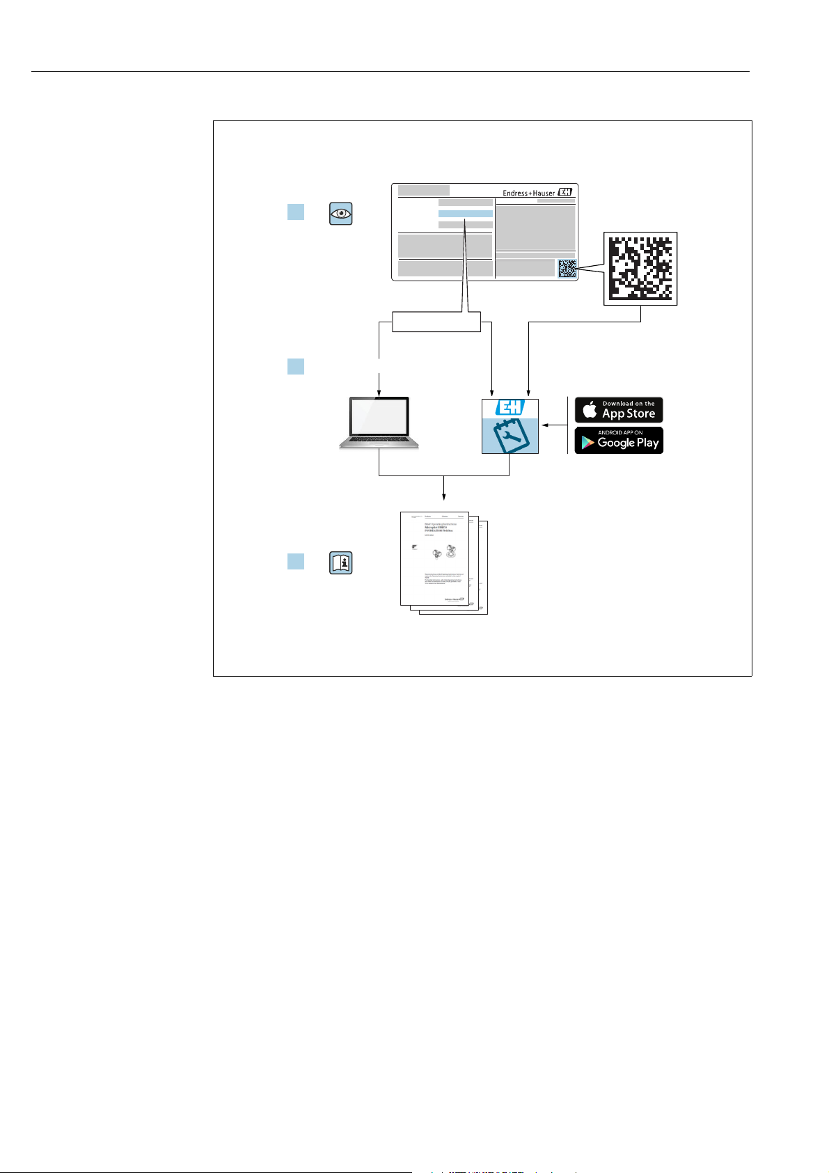
Order code:
Ext. ord. cd.:
Ser. no.:
www.endress.com/deviceviewer
Endress+Hauser
Operations App
XXXXXXXXXXXX
XXXXX-XXXXXX
XXX.XXXX.XX
Serial number
1.
3.
2.
A0023555
Make sure the document is stored in a safe place such that it is always available when
working on or with the device.
To avoid danger to individuals or the facility, read the "Basic safety instructions" section
carefully, as well as all other safety instructions in the document that are specific to
working procedures.
The manufacturer reserves the right to modify technical data without prior notice. Your
Endress+Hauser Sales Center will supply you with current information and updates to these
Instructions.
2 Endress+Hauser
Page 3

Deltabar S FMD77, FMD78, PMD75 with FOUNDATION Fieldbus
Table of contents
1 Document information . . . . . . . . . . . . . . 4
1.1 Document function . . . . . . . . . . . . . . . . . . . . . . . . . . 4
1.2 Symbols used . . . . . . . . . . . . . . . . . . . . . . . . . . . . . . . 4
1.3 Registered trademarks . . . . . . . . . . . . . . . . . . . . . . . 5
1.4 Terms and abbreviations . . . . . . . . . . . . . . . . . . . . . 6
1.5 Turn down calculation . . . . . . . . . . . . . . . . . . . . . . . 7
2 Basic safety instructions . . . . . . . . . . . . . 8
2.1 Requirements concerning the staff . . . . . . . . . . . . . 8
2.2 Designated use . . . . . . . . . . . . . . . . . . . . . . . . . . . . . 8
2.3 Workplace safety . . . . . . . . . . . . . . . . . . . . . . . . . . . 8
2.4 Operational safety . . . . . . . . . . . . . . . . . . . . . . . . . . . 8
2.5 Hazardous area . . . . . . . . . . . . . . . . . . . . . . . . . . . . . 9
2.6 Product safety . . . . . . . . . . . . . . . . . . . . . . . . . . . . . . 9
3 Identification . . . . . . . . . . . . . . . . . . . . . 10
3.1 Product identification . . . . . . . . . . . . . . . . . . . . . . 10
3.2 Device designation . . . . . . . . . . . . . . . . . . . . . . . . 10
3.3 Scope of delivery . . . . . . . . . . . . . . . . . . . . . . . . . . 12
3.4 CE mark, Declaration of Conformity . . . . . . . . . . 12
3.5 Registered trademarks . . . . . . . . . . . . . . . . . . . . . 12
4 Installation . . . . . . . . . . . . . . . . . . . . . . . 13
4.1 Incoming acceptance and storage . . . . . . . . . . . . 13
4.2 Installation conditions . . . . . . . . . . . . . . . . . . . . . 13
4.3 Installation instructions . . . . . . . . . . . . . . . . . . . . 14
4.4 Post-installation check . . . . . . . . . . . . . . . . . . . . . 30
5 Wiring . . . . . . . . . . . . . . . . . . . . . . . . . . . 31
5.1 Connecting the device . . . . . . . . . . . . . . . . . . . . . 31
5.2 Connecting the measuring unit . . . . . . . . . . . . . . 32
5.3 Overvoltage protection (optional) . . . . . . . . . . . . 33
5.4 Post-connection check . . . . . . . . . . . . . . . . . . . . . 33
7.6 Flow measurement . . . . . . . . . . . . . . . . . . . . . . . . . 67
7.7 Level measurement . . . . . . . . . . . . . . . . . . . . . . . . 70
7.8 Differential pressure measurement . . . . . . . . . . . 77
7.9 Scaling the OUT parameter . . . . . . . . . . . . . . . . . . 79
7.10 Configuring event behavior in accordance with
FOUNDATION Fieldbus Specification FF912 Field
Diagnostic Profile . . . . . . . . . . . . . . . . . . . . . . . . . . 80
8 Maintenance . . . . . . . . . . . . . . . . . . . . . 91
8.1 Cleaning instructions . . . . . . . . . . . . . . . . . . . . . . . 91
8.2 Exterior cleaning . . . . . . . . . . . . . . . . . . . . . . . . . . 91
9 Diagnostics and troubleshooting . . . . 92
9.1 Troubleshooting . . . . . . . . . . . . . . . . . . . . . . . . . . . 92
9.2 Diagnostic information on local display . . . . . . . . 93
9.3 Diagnostic event in the operating tool . . . . . . . . . 94
9.4 Diagnostic messages in the DIAGNOSTIC
Transducer Block (TRDDIAG) . . . . . . . . . . . . . . . . 95
9.5 Overview of diagnostic events . . . . . . . . . . . . . . . . 99
9.6 Response of outputs to errors . . . . . . . . . . . . . . 108
9.7 Confirming messages . . . . . . . . . . . . . . . . . . . . . 109
9.8 Repair . . . . . . . . . . . . . . . . . . . . . . . . . . . . . . . . . . 109
9.9 Repair of Ex-certified devices . . . . . . . . . . . . . . 110
9.10 Spare Parts . . . . . . . . . . . . . . . . . . . . . . . . . . . . . . 110
9.11 Return . . . . . . . . . . . . . . . . . . . . . . . . . . . . . . . . . 110
9.12 Disposal . . . . . . . . . . . . . . . . . . . . . . . . . . . . . . . . 110
9.13 Software history . . . . . . . . . . . . . . . . . . . . . . . . . 111
10 Technical data . . . . . . . . . . . . . . . . . . . 111
Index . . . . . . . . . . . . . . . . . . . . . . . . . . . 112
6 Operation. . . . . . . . . . . . . . . . . . . . . . . . . 34
6.1 Onsite display (optional) . . . . . . . . . . . . . . . . . . . 34
6.2 Operating elements . . . . . . . . . . . . . . . . . . . . . . . 36
6.3 FOUNDATION Fieldbus interface . . . . . . . . . . . . 38
6.4 Local operation – onsite display connected . . . . 51
6.5 HistoROM®/M-DAT (optional) . . . . . . . . . . . . . . 54
6.6 FieldCare . . . . . . . . . . . . . . . . . . . . . . . . . . . . . . . . 57
6.7 Locking/unlocking operation . . . . . . . . . . . . . . . 57
6.8 Simulation . . . . . . . . . . . . . . . . . . . . . . . . . . . . . . . 59
6.9 Factory setting (reset) . . . . . . . . . . . . . . . . . . . . . 59
7 Commissioning. . . . . . . . . . . . . . . . . . . . 62
7.1 Configuring messages . . . . . . . . . . . . . . . . . . . . . 62
7.2 Function check . . . . . . . . . . . . . . . . . . . . . . . . . . . 62
7.3 Commissioning via an FF configuration program . .
62
7.4 Selecting the language and measuring mode . . 64
7.5 Position adjustment . . . . . . . . . . . . . . . . . . . . . . . 65
Endress+Hauser 3
Page 4
Document information Deltabar S FMD77, FMD78, PMD75 with FOUNDATION Fieldbus
DANGER
WARNING
CAUTION
NOTICE
)
1 Document information
1.1 Document function
These Operating Instructions contain all the information that is required in various phases
of the life cycle of the device: from product identification, incoming acceptance and storage,
to mounting, connection, operation and commissioning through to troubleshooting,
maintenance and disposal.
1.2 Symbols used
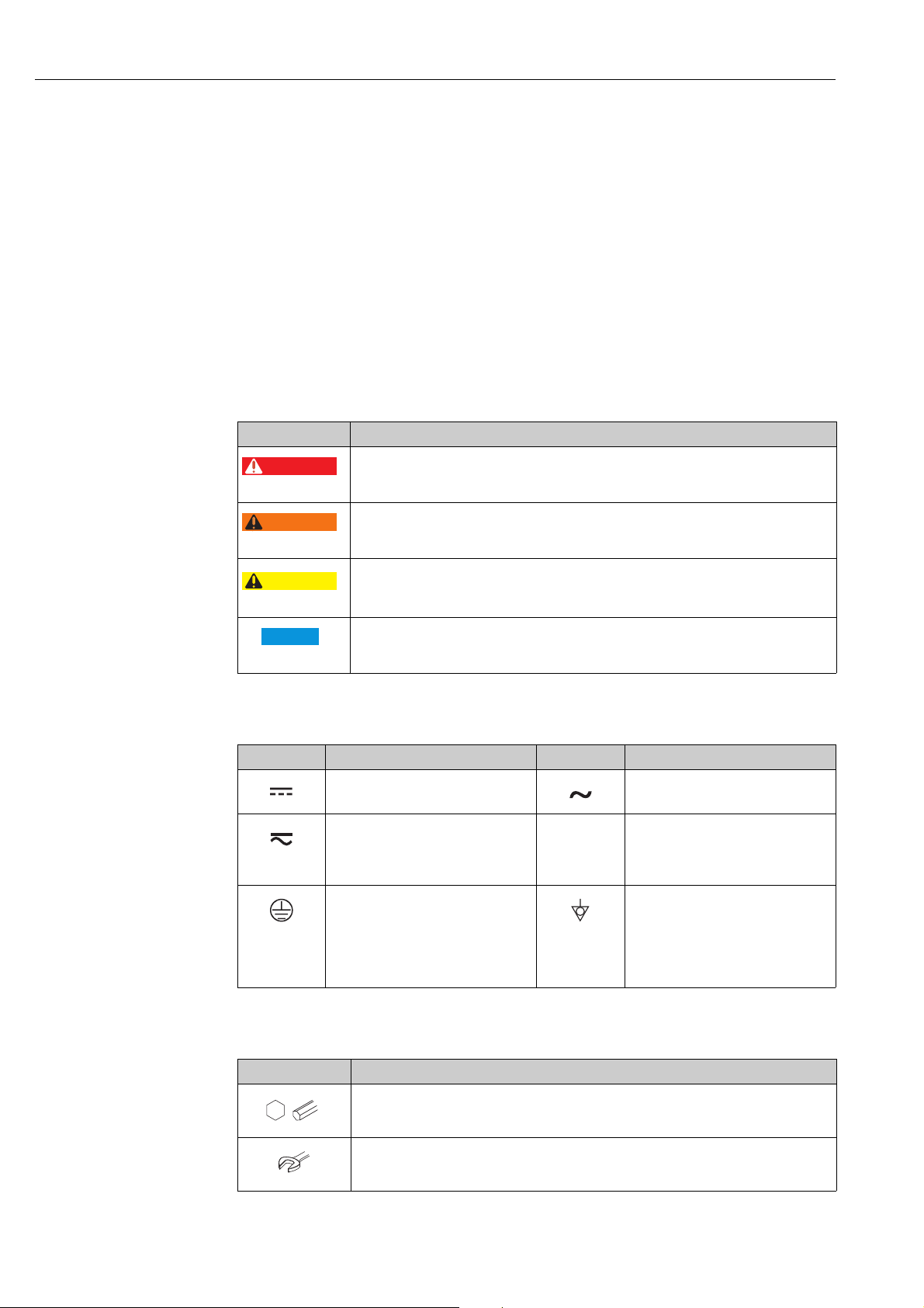
1.2.1 Safety symbols
Symbol Meaning
DANGER!
A0011189-DE
A0011190-DE
A0011191-DE
A0011192-DE
This symbol alerts you to a dangerous situation. Failure to avoid this situation will result in
seriousor fatal injury.
WARNING!
This symbol alerts you to a dangerous situation. Failure to avoid this situation can result in
seriousor fatal injury.
CAUTION!
This symbol alerts you to a dangerous situation. Failure to avoid this situation can result in
minoror medium injury.
NOTICE!
This symbol contains information on procedures and other facts which do not result in
personalinjury.
1.2.2 Electrical symbols
Symbol Meaning Symbol Meaning
Direct current Alternating current
Direct current and alternating current Ground connection
Protective ground connection
A terminal which must be connected
to ground prior to establishing any
other connections.
1.2.3 Tool symbols
Symbol Meaning
Allen key
A0011221
Hexagon wrench
A grounded terminal which, as far as
the operator is concerned, is grounded
via a grounding system.
Equipotential connection
A connection that has to be connected
to the plant grounding system: This
may be a potential equalization line or
a star grounding system depending on
national or company codes of practice.
A0011222
4 Endress+Hauser
Page 5
Deltabar S FMD77, FMD78, PMD75 with FOUNDATION Fieldbus Document information
,…,
1.
2.
3.
,…,
1.
2.
3.
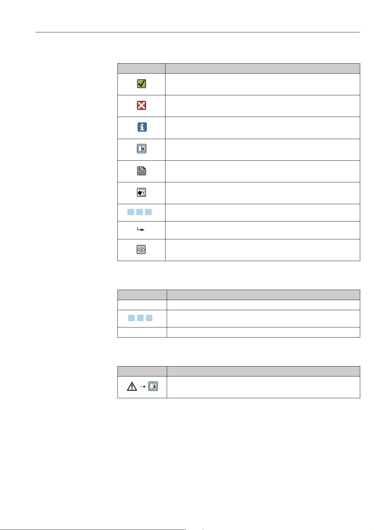
1.2.4 Symbols for certain types of information
Symbol Meaning
Permitted
Indicates procedures, processes or actions that are permitted.
A0011182
Forbidden
Indicates procedures, processes or actions that are forbidden.
A0011184
Tip
Indicates additional information.
A0011193
Reference to documentation
A0015482
Reference to page
A0015484
Reference to graphic
A0015487
Series of steps
A0031595
Result of a sequence of actions
A0018343
Visual inspection
A0015502
1.2.5 Symbols in graphics
Symbol Meaning
1, 2, 3, 4, ... Item numbers
Series of steps
A0031595
A, B, C, D, ... Views
1.2.6 Symbols at the device
Symbol Meaning
Safety instructions
Observe the safety instructions contained in the associated Operating Instructions.
A0019159
1.3 Registered trademarks
KALREZ, VITON, TEFLON
Registered trademarks of E.I. Du Pont de Nemours & Co., Wilmington, USA
TRI-CLAMP
Registered trademark of Ladish & Co., Inc., Kenosha, USA
®
TM
Fieldbus
FOUNDATION
Registered trademark of the FieldComm Group, Austin, USA
GORE-TEX
Registered trademarks of W.L. Gore & Associates, Inc., USA
Endress+Hauser 5
Page 6

Document information Deltabar S FMD77, FMD78, PMD75 with FOUNDATION Fieldbus
URL OPLMWP
LRL
0
p
LRV
URV
1
2
3
4
1.4 Terms and abbreviations
A0029505
Position Term/Abbreviation Explanation
1 OPL The OPL (over pressure limit = sensor overload limit) for the sensors
depends on the lowest-rated element, with regard to pressure, of the
selected components, i.e. the process connection must be taken into
consideration in addition to the measuring cell. Also observe pressuretemperature dependency. For the relevant standards and additional notes,
see technical information.
The OPL may be applied for a limited time period.
2 MWP The MWP (maximum working pressure) for the sensors depends on the
lowest-rated element, with regard to pressure, of the selected components,
i.e. the process connection has to be taken into consideration in addition to
the measuring cell. Also observe pressure-temperature dependency. For the
relevant standards and additional notes, see technical information.
The MWP may be applied for an unlimited time.
3Maximum sensor
measuring range
4 Calibrated/Adjusted
measuring span
p - Pressure
- LRL Lower range limit
-URL Upper range limit
- LRV Lower range value
-URV Upper range value
-TD Turn down
Range between LRL and URL
This span is the maximum calibratable/adjustable measuring span.
Range between LRV and URV
Factory setting: 0...URL
Other calibrated spans can be ordered with customised settings.
6 Endress+Hauser
Page 7

Deltabar S FMD77, FMD78, PMD75 with FOUNDATION Fieldbus Document information
LRV
URLURV
LRL
1 = 2
3
1.5 Turn down calculation
A0029545
Fig. 1:
1 Calibrated/Adjusted measuring span
2 Zero-based span
3 Upper range limit
Example
• Sensor: 10 bar (150 psi)
• Upper range limit (URL) = 10 bar (150 psi)
Turn down (TD):
TD =
|URV - LRV|
URL
• Calibrated/Adjusted measuring span: 0...5 bar
(0...75 psi)
• Lower range value (LRV) = 0 bar
• Upper range value (URV) = 5 bar (75 psi)
TD =
In this example, the TD is thus 2:1.
This span is based on the zero point.
|5 bar (75 psi) - 0 bar (0 psi)|
10 bar (150 psi)
=2
Endress+Hauser 7
Page 8

Basic safety instructions Deltabar S FMD77, FMD78, PMD75 with FOUNDATION Fieldbus
2 Basic safety instructions
2.1 Requirements concerning the staff
The personnel for installation, commissioning, diagnostics and maintenance must fulfill the
following requirements:
• Trained, qualified specialists: must have a relevant qualification for this specific function
and task
• Are authorized by the plant owner/operator
• Are familiar with federal/national regulations
• Before beginning work, the specialist staff must have read and understood the instructions
in the Operating Instructions and supplementary documentation as well as in the
certificates (depending on the application)
• Following instructions and basic conditions
The operating personnel must fulfill the following requirements:
• Being instructed and authorized according to the requirements of the task by the facility's
owner-operator
• Following the instructions in these Operating Instructions
2.2 Designated use
The Deltabar S is a differential pressure transmitter for measuring differential pressure, flow
and level.
2.2.1 Incorrect use
The manufacturer is not liable for damage caused by improper or non-designated use.
Verification for borderline cases:
For special fluids and fluids for cleaning, Endress+Hauser is glad to provide assistance in
verifying the corrosion resistance of fluid-wetted materials, but does not accept any
warranty or liability.
2.3 Workplace safety
For work on and with the device:
• Wear the required personal protective equipment according to federal/national
regulations.
• Switch off the supply voltage before connecting the device.
2.4 Operational safety
Risk of injury!
‣ Operate the device in proper technical condition and fail-safe condition only.
‣ The operator is responsible for interference-free operation of the device.
Conversions to the device
Unauthorized modifications to the device are not permitted and can lead to unforeseeable
dangers:
‣ If, despite this, modifications are required, consult with Endress+Hauser.
Repair
To ensure continued operational safety and reliability,
‣ Carry out repairs on the device only if they are expressly permitted.
‣ Observe federal/national regulations pertaining to repair of an electrical device.
‣ Use original spare parts and accessories from Endress+Hauser only.
8 Endress+Hauser
Page 9

Deltabar S FMD77, FMD78, PMD75 with FOUNDATION Fieldbus Basic safety instructions
2.5 Hazardous area
To eliminate a danger for persons or for the facility when the device is used in the hazardous
area (e.g. explosion protection, pressure vessel safety):
• Based on the nameplate, check whether the ordered device is permitted for the intended
use in the hazardous area.
• Observe the specifications in the separate supplementary documentation that is an
integral part of these Instructions.
2.6 Product safety
This measuring device is designed in accordance with good engineering practice to meet
state-of-the- art safety requirements, has been tested, and left the factory in a condition in
which they are safe to operate. It fulfills general safety requirements and legal requirements.
It also conforms to the EC directives listed in the device-specific EC declaration of conformity.
Endress+Hauser confirms this fact by applying the CE mark.
Endress+Hauser 9
Page 10
Identification Deltabar S FMD77, FMD78, PMD75 with FOUNDATION Fieldbus
Ser. no.:
Order code:
Ext. order code:
2
5
6
3
4
1
3 Identification
3.1 Product identification
The following options are available for identification of the measuring device:
• Nameplate specifications
• Order code with breakdown of the device features on the delivery note
• Enter serial numbers from nameplates in W@M Device Viewer
(www.endress.com/deviceviewer): All information about the measuring device is
displayed.
For an overview of the technical documentation provided, enter the serial number from the
nameplates in the W@M Device Viewer (www.endress.com/deviceviewer).
3.2 Device designation
3.2.1 Nameplates
• The MWP (maximum working pressure) is specified on the nameplate. This value refers
to a reference temperature of +20 °C (68°F) and may be applied to the device for an
unlimited time. Observe temperature dependency of the MWP. The pressure values
permitted at higher temperatures can be found in the standards EN 1092-1: 2001 Tab. 18
(With regard to their stability-temperature property, the materials 1.4435 and 1.4404 are
grouped together under 13EO in EN 1092-1 Tab. 18. The chemical composition of the two
materials can be identical.), ASME B 16.5a – 1998 Tab. 2-2.2 F316, ASME B 16.5a –
1998 Tab. 2.3.8 N10276, JIS B 2220.
• For PMD75, the MWP applies for the temperature ranges specified in the Technical
Information TI00382P in the "Ambient temperature range" and "Process temperature
limits" sections.
• The test pressure corresponds to the over pressure limit (OPL) of the device = MWP x 1.5.
• The Pressure Equipment Directive (2014/68/EU) uses the abbreviation "PS".
The abbreviation "PS" corresponds to the MWP (maximum working pressure) of the
measuring device.
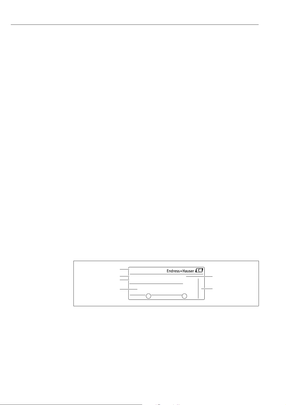
Aluminium housing (T14/T15) and stainless steel housing (T14)
Fig. 2: Nameplate
1Device name
2 Order code (for re-orders)
3 Extended order code (complete)
4Technical data
5 Serial number (for identification)
6 Address of manufacturer
10 Endress+Hauser
A0016056
Page 11
Deltabar S FMD77, FMD78, PMD75 with FOUNDATION Fieldbus Identification
2
1
1
2
7
3
4
5
6
1
Ser. no.:
Order code:
Ext. ord. cd.:
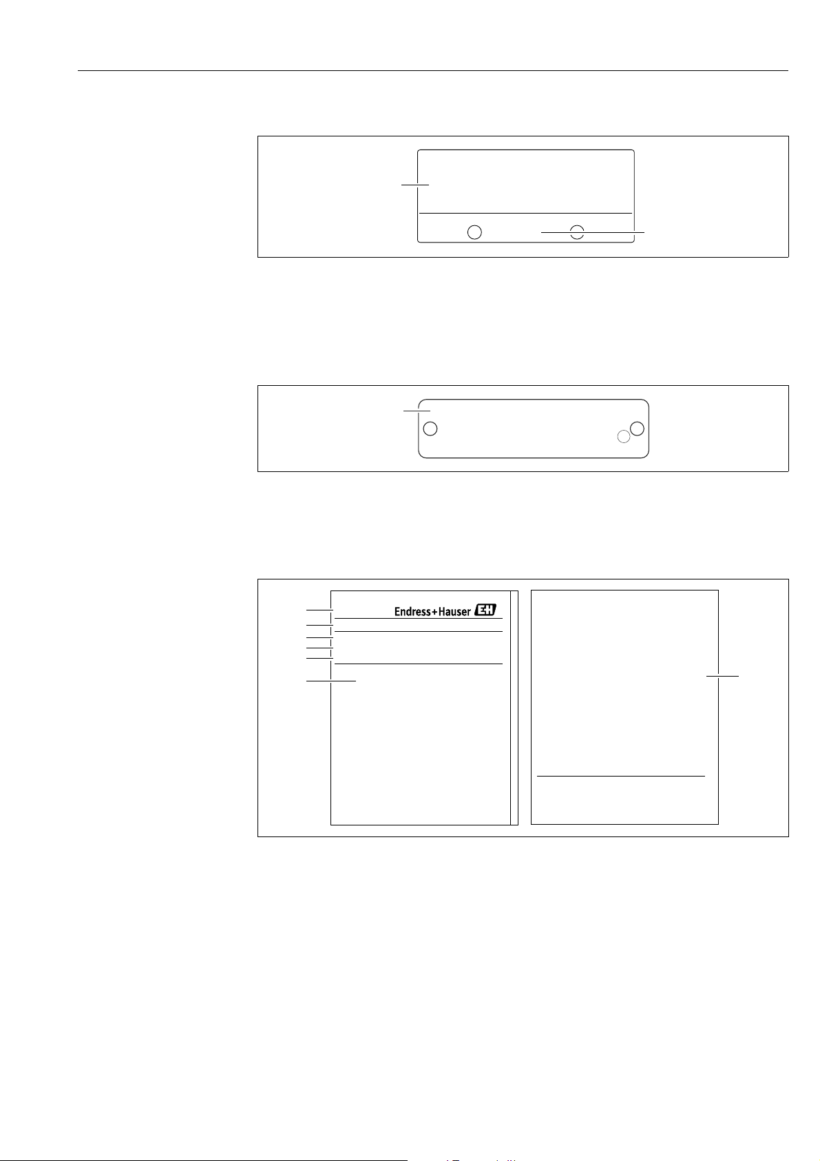
Devices for use in hazardous areas are fitted with an additional nameplate.
A0021222
Fig. 3: Additional nameplate
1 Approval-specific information
2 Document number for safety instructions or drawing number
Devices suitable for oxygen applications or with PVDF process connection are fitted with an
additional nameplate.
A0022683
Fig. 4: Additional nameplate
1 Application limits
Hygenic stainless steel housing (T17)
A0021552
Fig. 5: Nameplate
1 Device name
2 Address of manufacturer
3 Order code (for re-orders)
4 Extended order code (complete)
5 Serial number (for identification)
6Technical data
7 Approval-specific information and document number for safety instructions or drawing number
3.2.2 Identifying the sensor type
See parameter "Sensor Meas.Type" in Operating Instruction BA00303P.
Endress+Hauser 11
Page 12

Identification Deltabar S FMD77, FMD78, PMD75 with FOUNDATION Fieldbus
3.3 Scope of delivery
The scope of delivery comprises:
• Deltabar S differential pressure transmitter
• For PMD75 with side flanges made of AISI 316L or C22.8: additionally 2 vent valves, AISI
316L
• PMD75 with side flanges made of AISI 316L or C22.8 and side vent: additionally 4 locking
screws, AISI 316L
• For devices with the "HistoROM/M-DAT" option: CD-ROM with Endress+Hauser operating
program
• Optional accessories
Documentation supplied:
• Operating Instructions BA00301P and BA00303P are available via the Internet.
See: www.endress.com Download.
• Brief Operating Instructions KA01024P
• Fold-out brochure KA00252P
• Final inspection report
• Additional Safety Instructions with ATEX, IECEx and NEPSI devices
• Optional: factory calibration form, test certificates
3.4 CE mark, Declaration of Conformity
The devices are designed to meet state-of-the-art safety requirements, have been tested and
left the factory in a condition in which they are safe to operate. The devices comply with the
applicable standards and regulations as listed in the EC Declaration of Conformity and thus
comply with the statutory requirements of the EC Directives. Endress+Hauser confirms the
conformity of the device by affixing to it the CE mark.
3.5 Registered trademarks
KALREZ, VITON, TEFLON
Registered trademarks of E.I. Du Pont de Nemours & Co., Wilmington, USA
TRI-CLAMP
Registered trademark of Ladish & Co., Inc., Kenosha, USA
FOUNDATION
Registered trademark of the Fieldbus Foundation Austin, Texas, USA
TM
Fieldbus
12 Endress+Hauser
Page 13

Deltabar S FMD77, FMD78, PMD75 with FOUNDATION Fieldbus Installation
NOTICE
WARNING
!
1
4Installation
Incorrect handling!
Damage of the device!
‣ Disassembly of the screws with item number (1) is not permissible under any
circumstances and will result in loss of warranty.
A0025336
4.1 Incoming acceptance and storage
4.1.1 Incoming acceptance
• Check the packaging and the contents for damage.
• Check the shipment, make sure nothing is missing and that the scope of supply matches
your order.
4.1.2 Transport
Incorrect transport
Housing and diaphragm may be damaged and and there is a risk of injury!
‣ Transport the measuring device to the measuring point in its original packaging or by the
process connection (with secure transport protection for the diaphragm).
‣ Follow the safety instructions and transport conditions for devices of more than 18 kg
(39.69 lbs).
‣ Do not use capillaries as a carrying aid for the diaphragm seals.
4.1.3 Storage
The device must be stored in a dry, clean area and protected against impact (EN 837-2).
Storage temperature range:
• –40 to +90°C (–40 to +194 °F)
• Onsite display: –40 to +85°C (–40 to +185°F)
• Separate housing: –40 to +60°C (–40 to +140°F)
4.2 Installation conditions
4.2.1 Dimensions
For dimensions, please refer to the Technical Information for Deltabar S TI00382P,
"Mechanical construction" section.
Endress+Hauser 13
Page 14
Installation Deltabar S FMD77, FMD78, PMD75 with FOUNDATION Fieldbus
➀
➂
➃
+
–
➁
4.3 Installation instructions
• Due to the orientation of the Deltabar S, there may be a shift in the measured value, i.e.
when the container is empty or partially full, the measured value does not display zero. You
can correct this zero point shift using the "Zero" key on the electronic insert or externally
on the device or via the onsite display. ä 36, Section 6.2.1 "Position of the operating
elements", ä 37, Section 6.2.3 "Function of the operating elements – onsite display
connected" and ä 65, Section 7.5 "Position adjustment"..
• For FMD77 and FMD78, please refer to Section 4.3.4 "Installation instructions for devices
with diaphragm seals (FMD78)", ä 21.
• General recommendations for routing the pressure piping can be found in DIN 19210
"Methods for measurement of fluid flow; differential piping for flow measurement devices"
or the corresponding national or international standards.
• Using a three-way or five-way valve manifold allows for easy commissioning, installation
and maintenance without interrupting the process.
• When routing the pressure piping outdoors, ensure that sufficient antifreeze protection is
used, e.g. by using pipe heat tracing.
• Install the pressure piping with a monotonic gradient of at least 10%.
• To ensure optimal readability of the onsite display, it is possible to rotate the housing up
to 380°. ä 29, Section 4.3.9 "Rotating the housing".
• Endress+Hauser offers a mounting bracket for installing on pipes or walls.
ä 26, Section 4.3.7 "Wall and pipe-mounting (optional)".
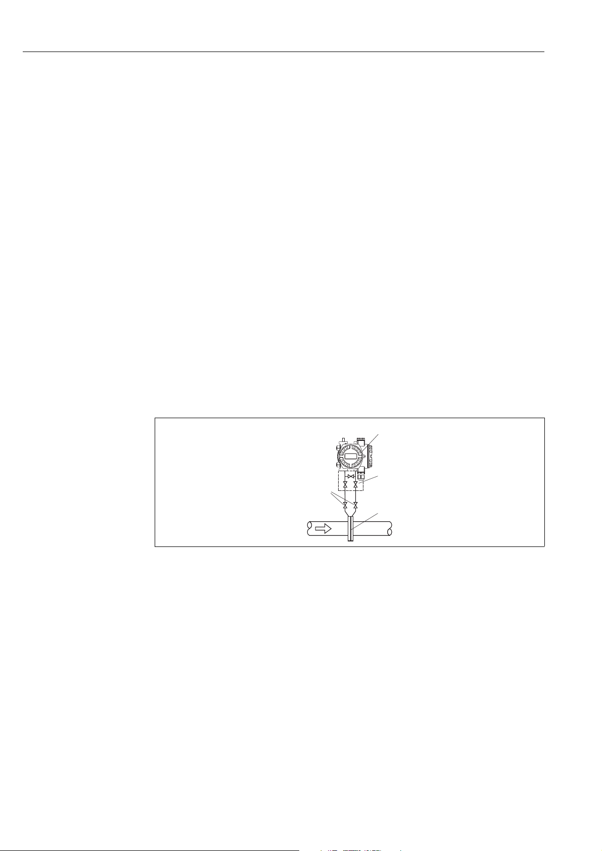
4.3.1 Installation for flow measurement
Flow measurement in gases with PMD75
P01-PMD75xxx-11-xx-xx-xx-000
Fig. 6: Measuring arrangement for flow measurement in gases with PMD75
1 Deltabar S, here PMD75
2 Three-way valve manifold
3 Shutoff valves
4 Orifice plate or Pitot tube
• Mount the Deltabar S above the measuring point so that the condensate can run off into
the process piping.
14 Endress+Hauser
Page 15
Deltabar S FMD77, FMD78, PMD75 with FOUNDATION Fieldbus Installation
➀
➁
➃
+
–
➂
➅
➄
➆
➂
➅
➄
+
–
➀
➂
➅
➁
➃
➄
➁
➃
➄
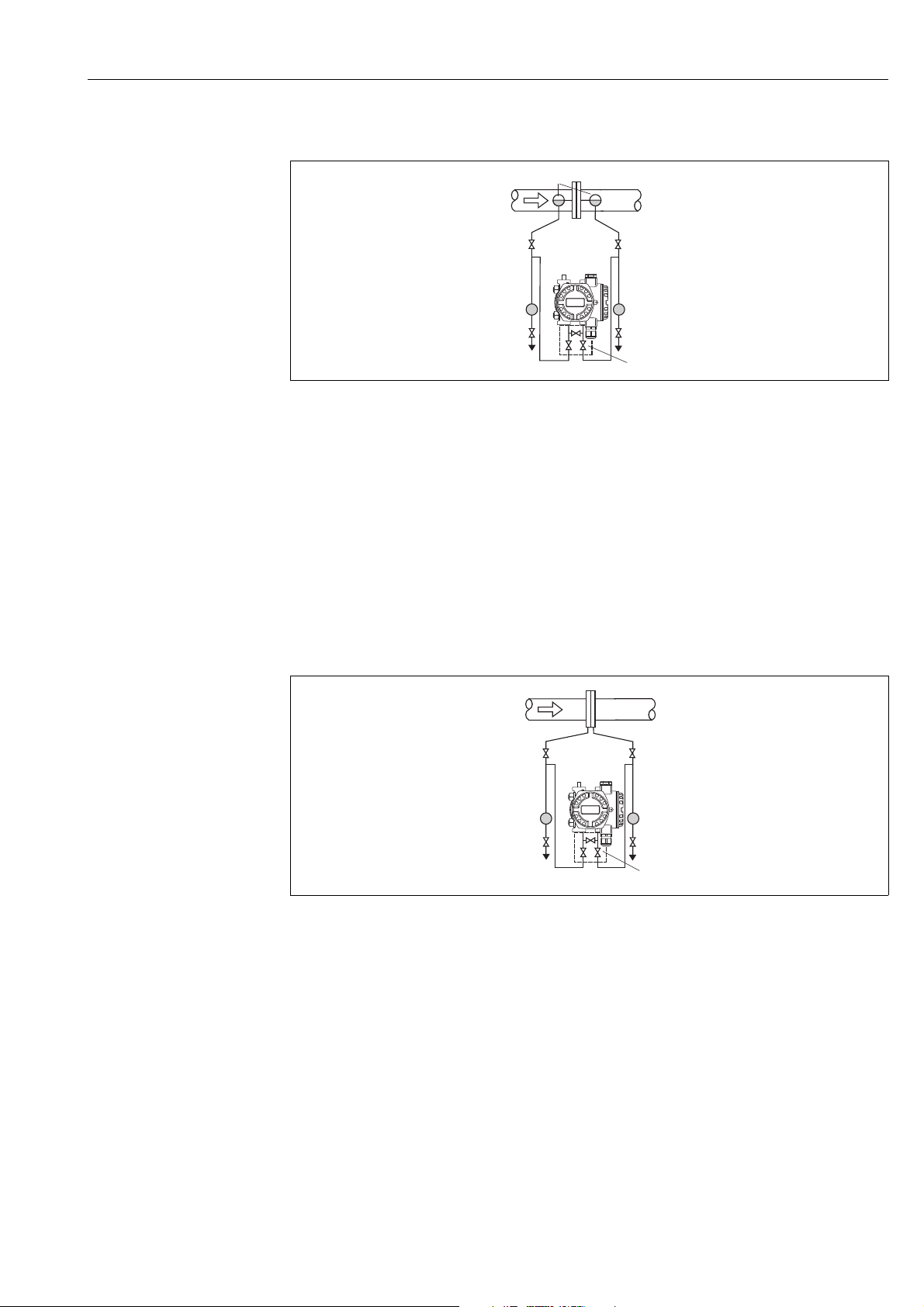
Flow measurement in steam with PMD75
P01-PMD75xxx-11-xx-xx-xx-001
Fig. 7: Measuring arrangement for flow measurement in steam with PMD75
1 Condensate traps
2 Orifice plate or Pitot tube
3Shutoff valves
4 Deltabar S, here PMD75
5Separator
6 Drain valves
7 Three-way valve manifold
• Mount the Deltabar S below the measuring point.
• Mount the condensate traps at the same level as the tapping points and at the same
distance to the Deltabar S.
• Prior to commissioning, fill the pressure piping to the level of the condensate traps.
Flow measurement in liquids with PMD75
P01-PMD75xxx-11-xx-xx-xx-002
Fig. 8: Measuring arrangement for flow measurement in liquids with PMD75
1 Orifice plate or Pitot tube
2Shutoff valves
3 Deltabar S, here PMD75
4Separator
5 Drain valves
6 Three-way valve manifold
• Mount the Deltabar S below the measuring point so that the pressure piping is always
filled with liquid and gas bubbles can run back into the process piping.
• When measuring in media with solid parts, such as dirty liquids, installing separators and
drain valves is useful for capturing and removing sediment.
Endress+Hauser 15
Page 16
Installation Deltabar S FMD77, FMD78, PMD75 with FOUNDATION Fieldbus
+
➃
➂
➀
➁
➄
p
atm
min.
p
atm
+
–
min.
max.
1
2
p
atm
p
atm
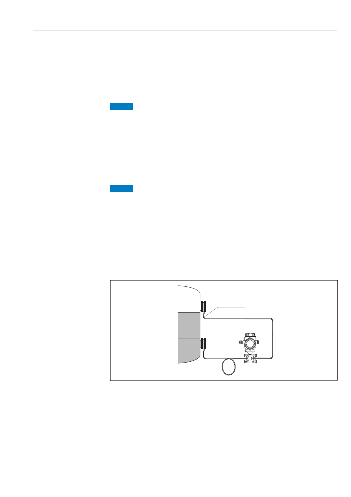
4.3.2 Installation for level measurement
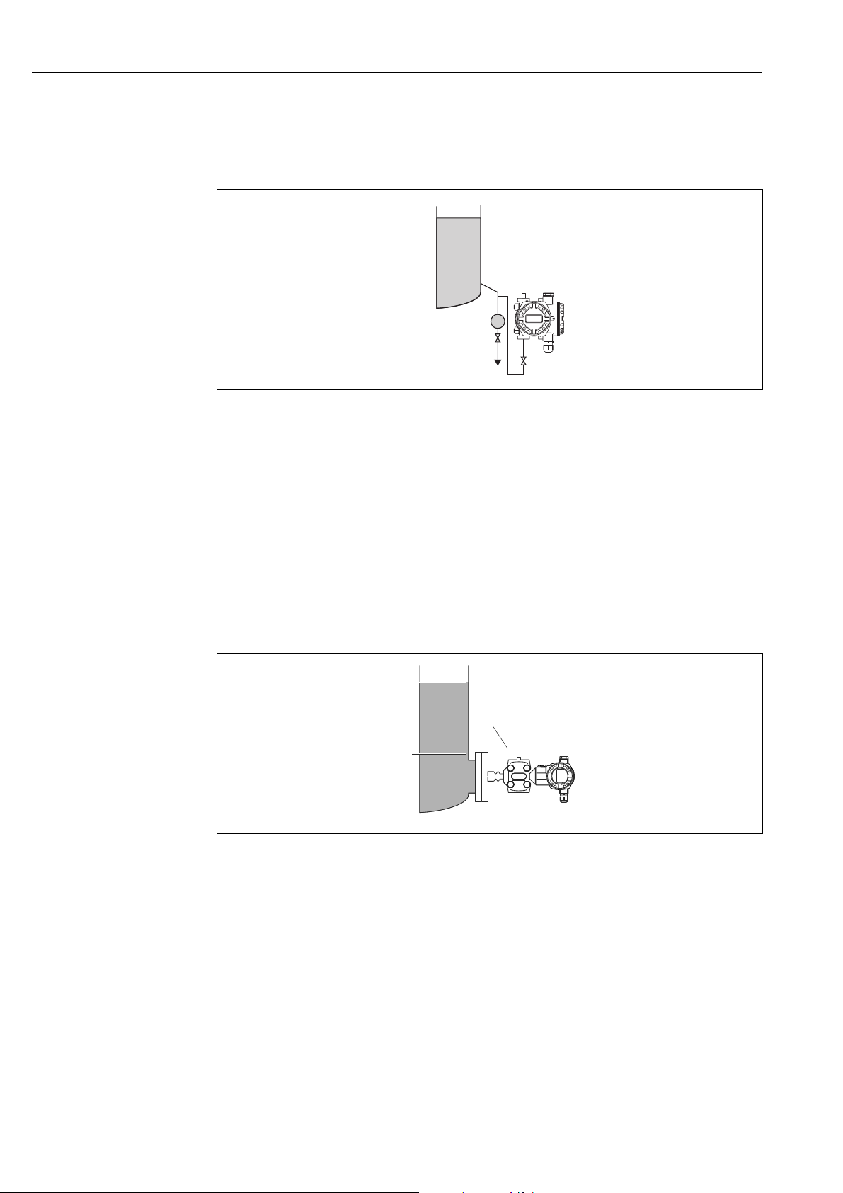
Level measurement in an open container with PMD75
P01-PMD75xxx-11-xx-xx-xx-003
Fig. 9: Measuring arrangement for level measurement in an open container with PMD75
1 The negative side is open to atmospheric pressure
2 Deltabar S, here PMD75
3 Shutoff valve
4Separator
5 Drain valve
• Mount the Deltabar S below the lower measuring connection so that the pressure piping
is always filled with liquid.
• The negative side is open to atmospheric pressure.
• When measuring in media with solid parts, such as dirty liquids, installing separators and
drain valves is useful for capturing and removing sediment.
Level measurement in an open container with FMD77
A0024164
Fig. 10: Measuring arrangement for level measurement in an open container with FMD77
1 Deltabar S, here FMD77
2 The negative side is open to atmospheric pressure
• Mount the Deltabar S directly on the container. ä 23, Section 4.3.5 "Seal for flange
mounting".
• The negative side is open to atmospheric pressure.
16 Endress+Hauser
Page 17
Deltabar S FMD77, FMD78, PMD75 with FOUNDATION Fieldbus Installation
+
–
➀
➂
➃
➄
➁
➀
➂
➃
min.
max.
+
–
min.
max.
1
2
3
4
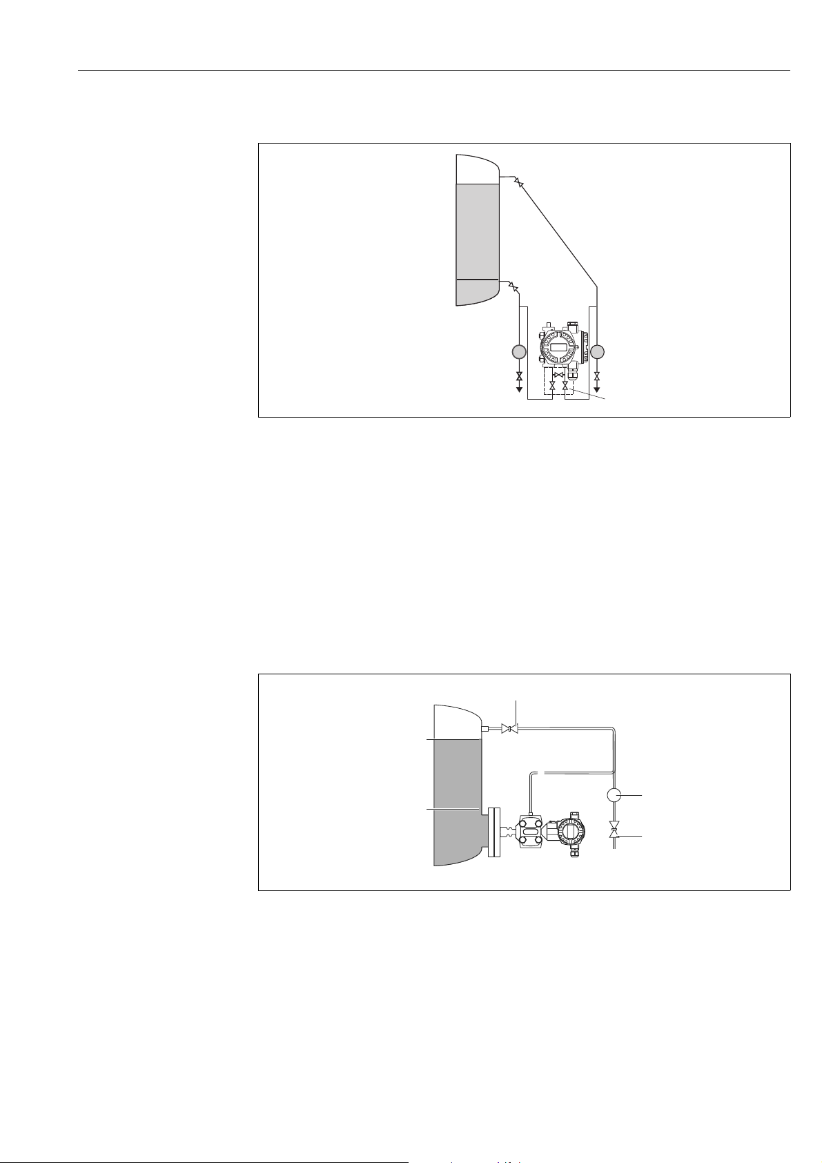
Level measurement in a closed container with PMD75
P01-PMD75xxx-11-xx-xx-xx-004
Fig. 11: Measuring arrangement for level measurement in a closed container with PMD75
1Shutoff valves
2 Deltabar S, PMD75
3Separator
4 Drain valves
5 Three-way valve manifold
• Mount the Deltabar S below the lower measuring connection so that the pressure piping
is always filled with liquid.
• Always connect the impulse piping of negative side above the maximum level.
• When measuring in media with solid parts, such as dirty liquids, installing separators and
drain valves is useful for capturing and removing sediment.
Level measurement in a closed container with FMD77
A0024163
Fig. 12: Measuring arrangement for level measurement in a closed container with FMD77
Endress+Hauser 17
1 Shutoff valve
2Separator
3 Drain valve
4 Deltabar S, here FMD77
• Mount the Deltabar S directly on the container. ä 23, Section 4.3.5 "Seal for flange
mounting".
• Always connect the impulse piping of negative side above the maximum level.
• When measuring in media with solid parts, such as dirty liquids, installing separators and
drain valves is useful for capturing and removing sediment.
Page 18

Installation Deltabar S FMD77, FMD78, PMD75 with FOUNDATION Fieldbus
+
–
➀
min.
max.
+
–
➂
➀
➁
➃
➄
➅
➃
➄
min.
max.
➁
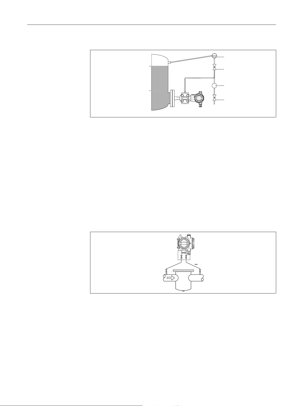
Level measurement in a closed container with FMD78
P01-FMD78xxx-11-xx-xx-xx-000
Fig. 13: Measuring arrangement for level measurement in a closed container with FMD78
1 Deltabar S, here FMD78
• Mount the Deltabar S below the lower diaphragm seal. ä 21, Section 4.3.4 "Installation
instructions for devices with diaphragm seals (FMD78)".
• The ambient temperature should be the same for both capillaries.
Level measurement is only ensured between the upper edge of the lower diaphragm seal and
the lower edge of the upper diaphragm seal.
Level measurement in a closed container with superimposed steam with PMD75
P01-PMD75xxx-11-xx-xx-xx-005
Fig. 14: Measuring arrangement for level measurement in a container with superimposed steam with PMD75
1 Condensate trap
2 Shutoff valves
3 Deltabar S, here PMD75
4Separator
5 Drain valves
6 Three-way valve manifold
• Mount the Deltabar S below the lower measuring connection so that the pressure piping
is always filled with liquid.
• Always connect the impulse piping of negative side above the maximum level.
• A condensate trap ensures constant pressure on the negative side.
• When measuring in media with solid parts, such as dirty liquids, installing separators and
drain valves is useful for capturing and removing sediment.
18 Endress+Hauser
Page 19
Deltabar S FMD77, FMD78, PMD75 with FOUNDATION Fieldbus Installation
+
–
min.
max.
3
4
2
1
5
+
➂
➀
➁
➂
➃
Level measurement in a closed container with superimposed steam with FMD77
A0024162
Fig. 15: Measuring arrangement for level measurement in a container with superimposed steam with FMD77
1 Condensate trap
2 Shutoff valve
3Separator
4 Drain valve
5 Deltabar S, here FMD77
• Mount the Deltabar S directly on the container. ä 23, Section 4.3.5 "Seal for flange
mounting".
• Always connect the impulse piping of negative side above the maximum level.
• A condensate trap ensures constant pressure on the negative side.
• When measuring in media with solid parts, such as dirty liquids, installing separators and
drain valves is useful for capturing and removing sediment.
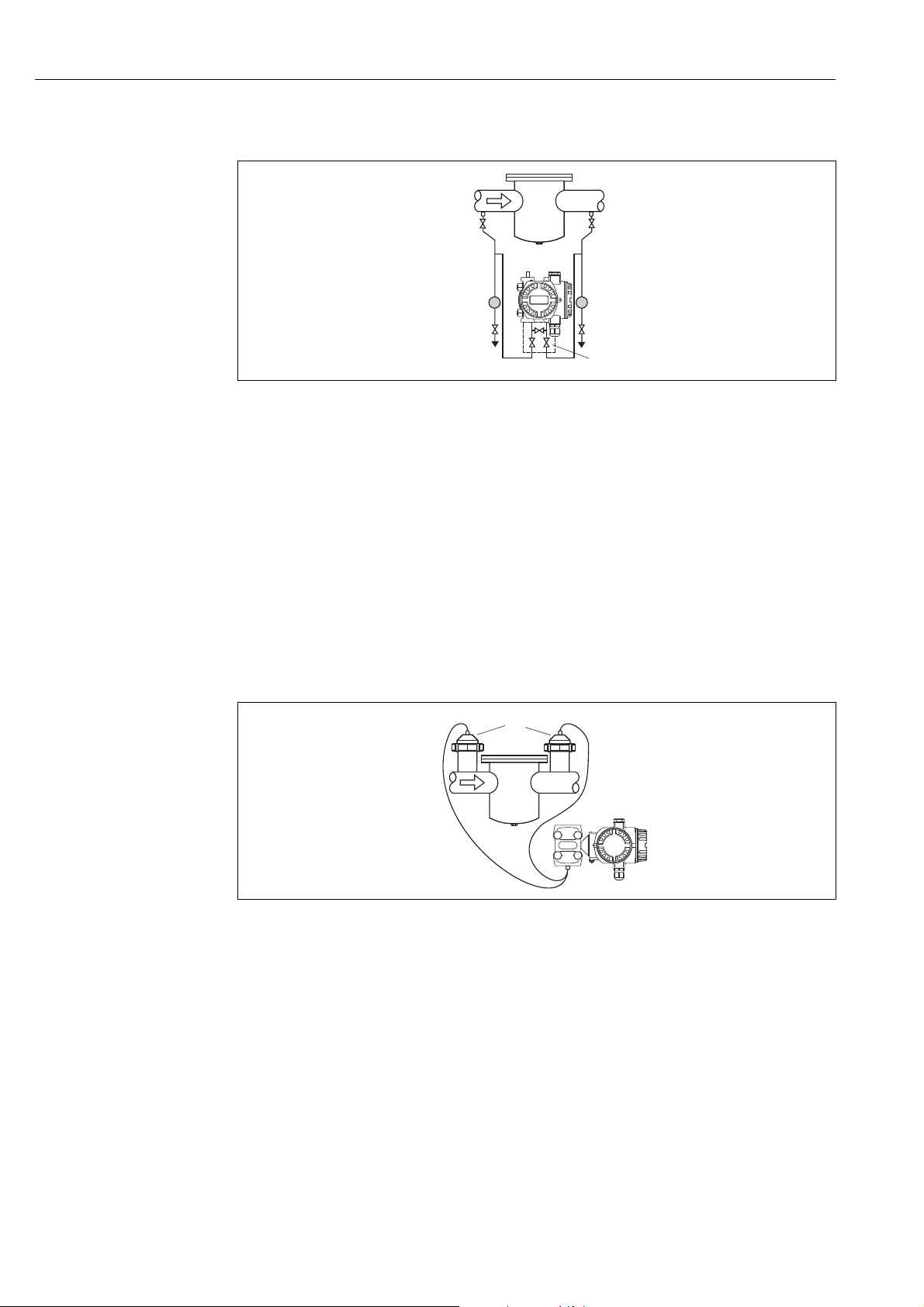
4.3.3 Installation for differential pressure measurement
Differential pressure measurement in gases and steam with PMD75
P01-PMD75xxx-11-xx-xx-xx-006
Fig. 16: Measuring arrangement for differential pressure measurement in gases and steam with PMD75
1 Deltabar S, here PMD75
2 Three-way valve manifold
3Shutoff valves
4 e.g. filter
• Mount the Deltabar S above the measuring point so that the condensate can run off into
the process piping.
Endress+Hauser 19
Page 20
Installation Deltabar S FMD77, FMD78, PMD75 with FOUNDATION Fieldbus
+
–
➂
➅
➁➁
➄
➃
➄
➃
➀
+
–
➂
➁
➃
➀
➁
Differential pressure measurement in liquids with PMD75
P01-PMD75xxx-11-xx-xx-xx-007
Fig. 17: Measuring arrangement for differential pressure measurement in liquids with PMD75
1 e.g. filter
2 Shutoff valves
3 Deltabar S, here PMD75
4Separator
5 Drain valves
6 Three-way valve manifold
• Mount the Deltabar S below the measuring point so that the pressure piping is always
filled with liquid and gas bubbles can run back into the process piping.
• When measuring in media with solid parts, such as dirty liquids, installing separators and
drain valves is useful for capturing and removing sediment.
Differential pressure measurement in gases, steam and liquids with FMD78
P01-FMD78xxx-11-xx-xx-xx-000
Fig. 18: Measuring arrangement for differential pressure measurement in gases, steam and liquids with FMD78
1Diaphragm seal
2 Capillary
3 e.g. filter
4 Deltabar S, here FMD78
• Mount the diaphragm seal with capillaries at the top or on the side on the piping.
• For vacuum applications: mount the Deltabar S below the measuring point. ä 22,
Section 4.3.4, "Vacuum application (FMD78)".
• The ambient temperature should be the same for both capillaries.
20 Endress+Hauser
Page 21
Deltabar S FMD77, FMD78, PMD75 with FOUNDATION Fieldbus Installation
NOTICE
NOTICE
+ –
+
–
≥ 100 mm
4.3.4 Installation instructions for devices with diaphragm seals
(FMD78)
• Please note that the hydrostatic pressure of the liquid columns in the capillaries can cause
zero point shift. The zero point shift can be corrected.
• Do not clean or touch the process isolating diaphragm of the diaphragm seal with hard or
pointed objects.
• Do not remove process isolating diaphragm protection until shortly before installation.
Improper handling!
Damage to the device!
‣ A diaphragm seal and the pressure transmitter together form a closed, oil-filled
calibrated system. The fill fluid hole is sealed and may not be opened.
‣ When using a mounting bracket, sufficient strain relief must be ensured for the
capillaries in order to prevent the capillary bending down (bending radius 100
(3.94 in)).
‣ Please observe the application limits of the diaphragm seal filling oil as detailed in the
Technical Information for Deltabar S TI00382P, "Planning instructions for diaphragm
seal systems" section.
In order to obtain more precise measurement results and to avoid a defect in the device,
mount the capillaries as follows:
‣ Vibration-free (in order to avoid additional pressure fluctuations)
‣ Not in the vicinity of heating or cooling lines
‣ Insulate if the ambient temperature is below or above the reference temperature
‣ With a bending radius of 100 mm (3.94 in).
‣ Do not use the capillaries as a carrying aid for the diaphragm seals!
‣ The ambient temperature and length of both capillaries should be the same when using
two-sided diaphragm seal systems.
‣ Two diaphragm seals which are the same (e.g. with regard to diameter, material, etc.)
should always be used for the negative and positive side (standard delivery).
P01-FMD78xxx-11-xx-xx-xx-005
Fig. 19: Mounting Deltabar S, FMD78 with diaphragm seals and capillaries, recommended mounting for vacuum applications:
Endress+Hauser 21
mount pressure transmitter below the lowest diaphragm seal!
Page 22
Installation Deltabar S FMD77, FMD78, PMD75 with FOUNDATION Fieldbus
+
–
H1
1
2
3
4
5
A
B
0.0
2.0
4.0
6.0
8.0
10.0
12.0
50 100 300 400 500 600 700 800 900 1000200
[mbar ]
abs
[m]
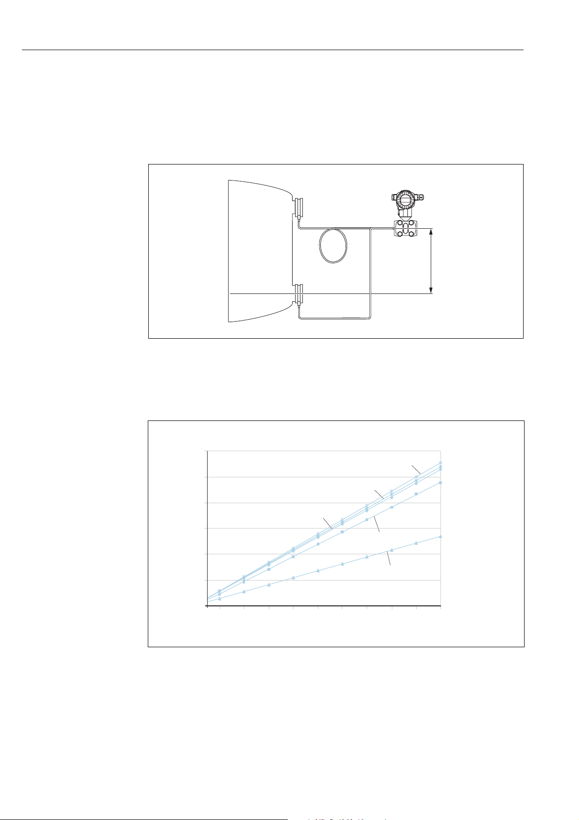
Vacuum application (FMD78)
For applications under vacuum, Endress+Hauser recommends mounting the pressure
transmitter below the diaphragm seal. This prevents vacuum loading of the diaphragm seal
caused by the presence of fill fluid in the capillary.
When the pressure transmitter is mounted above the diaphragm seal, the maximum height
difference H1 in accordance with the illustrations below must not be exceeded.
Fig. 20: Installation above the lower diaphragm seal
The maximum height difference depends on the density of the filling oil and the smallest
ever pressure that is permitted to occur at the diaphragm seal (empty vessel), see illustration
below:
Fig. 21: Diagram of maximum installation height above the lower diaphragm seal for vacuum applications depending on the
A Height difference H1
B Pressure at diaphragm seal
1 Low temperature oil
2 Vegetable oil
3 Silicone oil
4 High-temperature oil
5Inert oil
pressure at the diaphragm seal on the positive side
A0023986-en
A0023983
22 Endress+Hauser
Page 23
Deltabar S FMD77, FMD78, PMD75 with FOUNDATION Fieldbus Installation
NOTICE
12
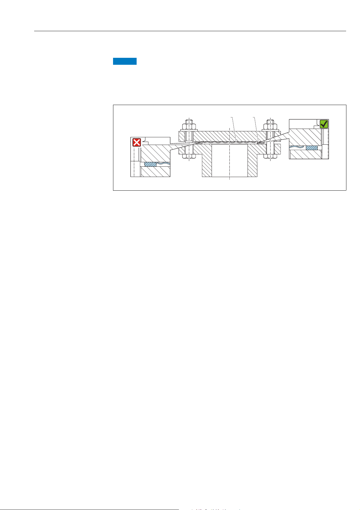
4.3.5 Seal for flange mounting
Distorted measurement results.
The seal is not allowed to press on the process isolating diaphragm as this could affect the
measurement result.
‣ Ensure that the seal is not touching the process isolating diaphragm.
A0017743
Fig. 22:
1 Process isolating diaphragm
2Seal
Endress+Hauser 23
Page 24
Installation Deltabar S FMD77, FMD78, PMD75 with FOUNDATION Fieldbus
30 (1.18)
T
a
T
P
53 (2.09)
A
C
B
D
100 (3.94)
77 (3.03)
A, B
T
a
T
P
T
1
1
1
1
p
T
a
+32
60
55
+85
50
45
140
131
+185122
113
200
85
−70
300
392
185
+32
−40
−94
572
+400+752
T
a
[°C]
[°F]
[°C][°F]
T
p
A
B
D
−−−40 35 30
−−−40 31 22
0
0
−40
C
C, D
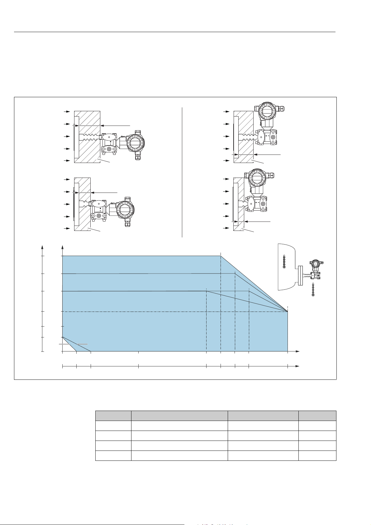
4.3.6 Heat insulation – FMD77
The FMD77 must only be insulated up to a certain height. The maximum permitted
insulation height applies to an insulation material with a heat conductivity 0.04 W/
(m x K) and to the maximum permitted ambient and process temperature. The data were
determined under the most critical application "quiescent air".
A0025889
1)
Fig. 23: Maximum insulation height
1 Insulation material
Without insulation, the ambient temperature decreases by 5 K.
Position Design Temperature isolator Option
A Transmitter horizontally long MA
B Transmitter vertical long MB
C Transmitter horizontally short MC
D Transmitter vertical short MD
1) Product Configurator, order code for "Process connection"
24 Endress+Hauser
Page 25

Deltabar S FMD77, FMD78, PMD75 with FOUNDATION Fieldbus Installation
T
U
T
P
E
+
–
100 (3.94)
1
A0023984
Fig. 24: Maximum insulation height
1 Insulation material
Position Design Ambient temperature T
E U-bracket, Transmitter horizontally
70 °C (158 °F) max. 350 °C (662 °F) , depending on
(for devices which require a CRN approval)
U
Process temperature T
P
the diaphragm seal filling oil used
Option
2)
F Compact version, Transmitter vertical - - 5, 6, 7, 8
1) Product Configurator, order code for "Process connection"
2) In combination with CSA approval.
1)
Endress+Hauser 25
Page 26
Installation Deltabar S FMD77, FMD78, PMD75 with FOUNDATION Fieldbus
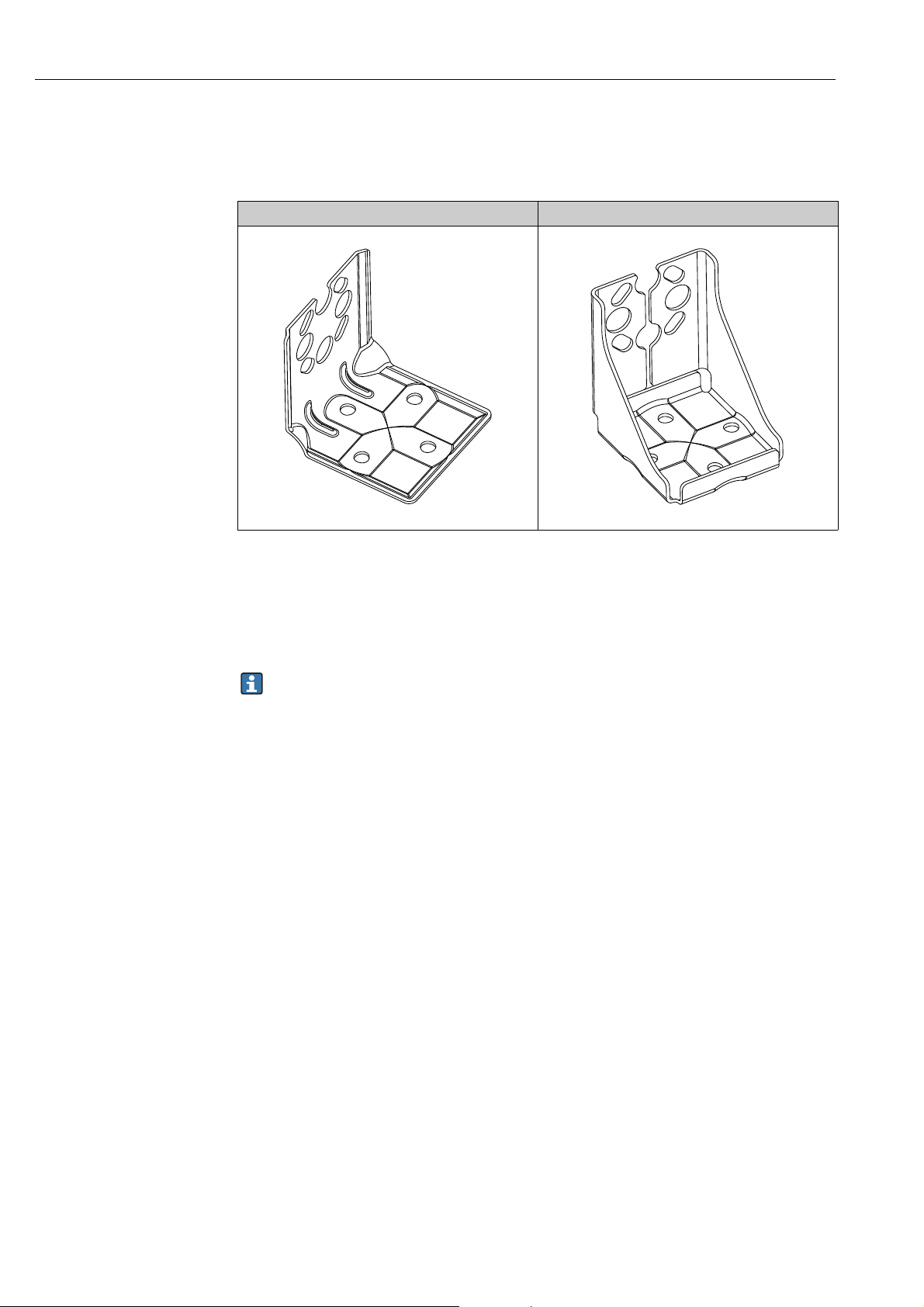
4.3.7 Wall and pipe-mounting (optional)
Endress+Hauser offers the following mounting brackets for installing the device on pipes or
walls:
Standard design Heavy duty design
A0031326 A0031327
The standard mounting bracket version is not suitable for use in an application subject to
vibrations.
The vibration resistance of the reinforced version of the mounting bracket has been tested
according to IEC 61298-3, see the "Vibration resistance" section in the technical
documentation TI00382P.
When using a valve block, the block's dimensions must be taken into account.
Bracket for wall and pipe mounting including retaining bracket for pipe mounting and two
nuts.
material of the screws used to secure the device depend on the order code.
Technical data (e.g. dimensions or order numbers for screws) see accessory document
SD01553P/00/EN.
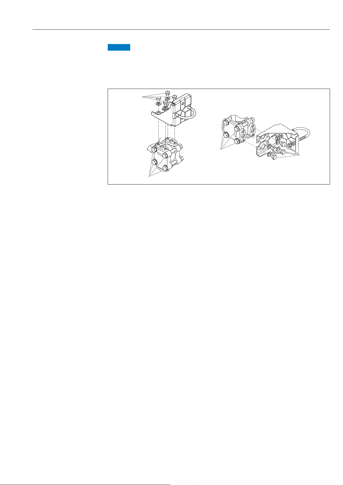
Please note the following when mounting:
• To prevent the mounting screws from scoring, lubricate them with a multi-purpose grease
prior to mounting.
• In the case of pipe mounting, the nuts on the bracket must be tightened uniformly with a
torque of at least 30 Nm (22.13 lbf ft).
• For installation purposes, only use the screws with item number (2) (see the following
diagram).
26 Endress+Hauser
Page 27
Deltabar S FMD77, FMD78, PMD75 with FOUNDATION Fieldbus Installation
NOTICE
1
2
1
2
Incorrect handling!
Damage of the device!
‣ Disassembly of the screws with item number (1) is not permissible under any
circumstances and will result in loss of warranty.
A0025335
Endress+Hauser 27
Page 28
Installation Deltabar S FMD77, FMD78, PMD75 with FOUNDATION Fieldbus
r ³ 120 mm
1
2
4
5
6
7
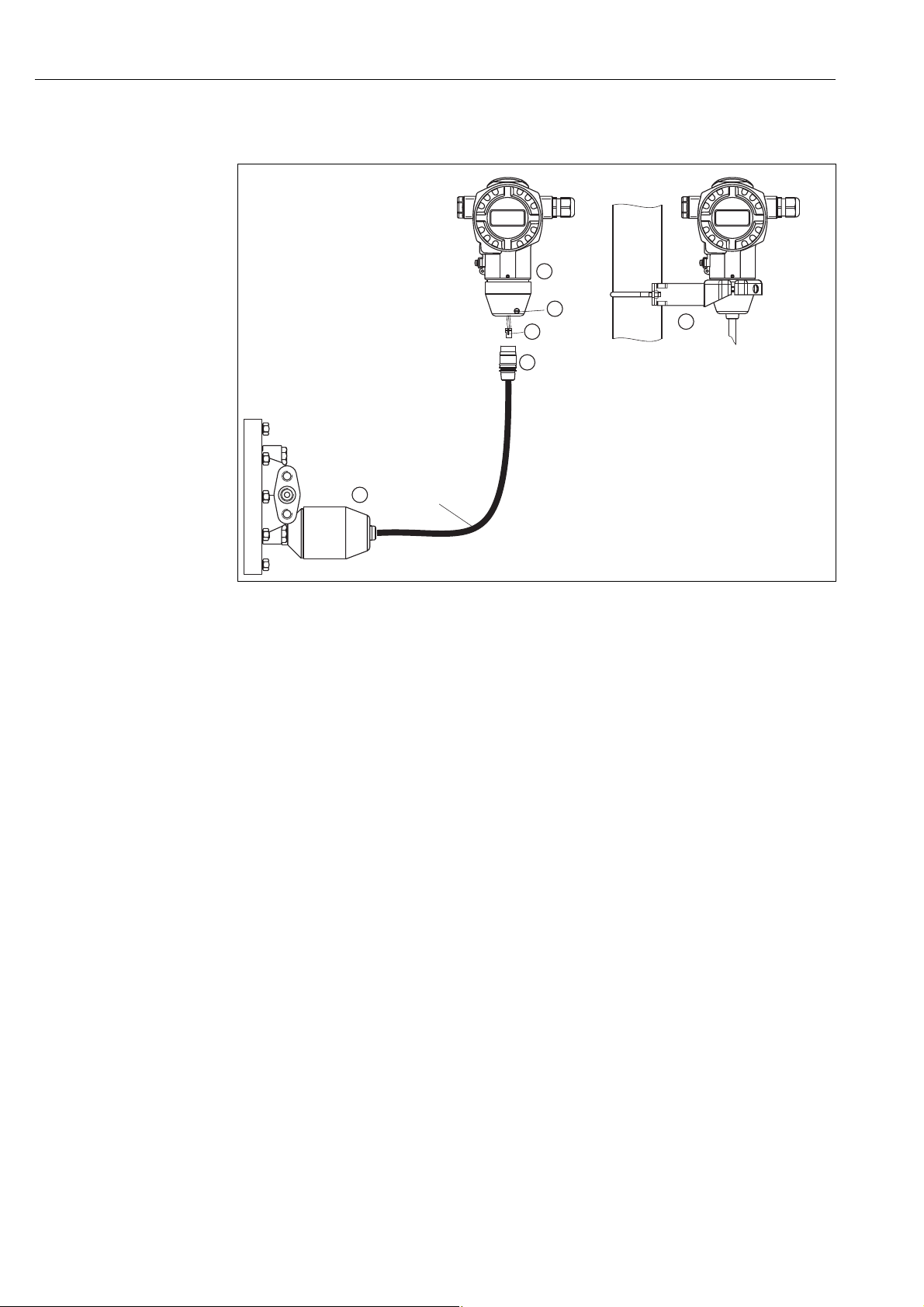
4.3.8 Assembling and mounting the "separate housing" version
P01-xMD7xxxx-11-xx-xx-xx-011
Fig. 25: "Separate housing" version
1 In the "separate housing" version, the sensor is supplied with the process connection and cable ready-fitted.
2 Cable with connection jack
4Plug
5Locking screw
6 Housing fitted with housing adapter, included
7 Mounting bracket suitable for wall and pipe mounting, included
Assembly and mounting
1. Insert the 10-pin connector (item 4) into the corresponding connection jack of the cable
(item 2).
2. Plug the cable into the housing adapter (item 6).
3. Tighten the locking screw (item 6).
4. Mount the housing on a wall or pipe using the mounting bracket (item 7).
When mounting on a pipe, tighten the nuts on the bracket uniformly with a torque of
at least 5 Nm (3.69 lbs ft).
Mount the cable with a bending radius (r) 120 mm (4.72 in).
28 Endress+Hauser
Page 29
Deltabar S FMD77, FMD78, PMD75 with FOUNDATION Fieldbus Installation
NOTICE
NOTICE
T14
T15
T17
2 3
+
–
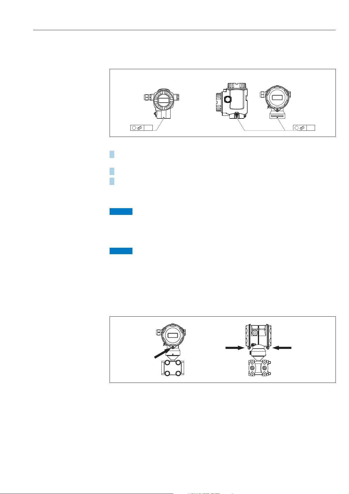
4.3.9 Rotating the housing
The housing can be rotated up to 380° by loosening the Allen screw.
A0019996
1. T14 housing: Loosen setscrew with a 2 mm (0.08 in) Allen key.
T15 andT17 housing: Loosen setscrew with a 3 mm (0.12 in) Allen key.
2. Rotate housing (max. up to 380 °).
3. Retighten setscrew with 1 Nm (0,74 lbf ft.
4.3.10 Closing the housing cover
Devices with EPDM cover seal - transmitter leakiness!
Mineral-based, animal-based or vegetable-based lubricants cause the EPDM cover seal to
swell and the transmitter to become leaky.
‣ The thread is coated at the factory and therefore does not require any lubrication.
The housing cover can no longer be closed.
Damaged thread!
‣ When closing the housing cover, please ensure that the thread of the cover and housing
are free from dirt, e.g. sand.If you feel any resistance when closing the cover, check the
thread on both again to ensure that they are free from dirt.
Closing the covers on the hygienic stainless steel housing (T17)
Fig. 26: Closing the covers
The covers for the terminal and electronics compartment are hooked into the housing and
closed with a screw. These screws should be tightened handtight (2 Nm (1.48 lbf ft)) to the
stop to ensure that the covers sit tightly.
Endress+Hauser 29
P01-PMD75xxx-17-xx-xx-xx-000
Page 30

Installation Deltabar S FMD77, FMD78, PMD75 with FOUNDATION Fieldbus
4.4 Post-installation check
After installing the device, carry out the following checks:
• Are all screws firmly tightened?
• Are the housing covers screwed down tight?
• Are all locking screws and vent valves firmly tightened?
30 Endress+Hauser
Page 31

Deltabar S FMD77, FMD78, PMD75 with FOUNDATION Fieldbus Wiring
WARNING
!
WARNING
!
➀
➁
➂
➃
➄
FF FF
FF FF
5 Wiring
5.1 Connecting the device
Risk of electric shock!
If the operating voltage is > 35 VDC: Dangerous contact voltage at terminals.
‣ In a wet environment, do not open the cover if voltage is present.
Limitation of electrical safety due to incorrect connection!
• Risk of electric shock and/or explosion in hazardous areas! In a wet environment, do not
open the cover if voltage is present.
• When using the measuring device in hazardous areas, installation must comply with the
corresponding national standards and regulations and the Safety Instructions or
Installation or Control Drawings.
• Devices with integrated overvoltage protection must be grounded.
• Protective circuits against reverse polarity, HF influences and overvoltage peaks are
installed.
• The supply voltage must match the power supply on the nameplate. ( ä 10,
Section 3.2.1 "Nameplates".)
• Switch off the supply voltage before connecting the device.
• Remove the housing cover of the terminal compartment.
• Guide the cable through the gland. For cable specifications, ä 32, Section 5.2.4.
• Connect the device in accordance with the following diagram.
• Screw down the housing cover.
• Switch on the supply voltage.
P01-xMx7xxxx-04-xx-xx-xx-009
Fig. 27: Electrical connection of FOUNDATION Fieldbus
1Housing
2 Internal ground terminal
3 External ground terminal
4 Supply voltage, for version in non-hazardous area = 9 to 32 V DC
5 Devices with integrated overvoltage protection are labeled OVP (overvoltage protection) here.
Please refer also to Section 5.2.1 "Supply voltage",
ä
32.
Endress+Hauser 31
Page 32

Wiring Deltabar S FMD77, FMD78, PMD75 with FOUNDATION Fieldbus
WARNING
!
4
2
31
5.1.1 Connecting devices with 7/8" plug
PIN assignment for 7/8" connector PIN Meaning
PIN Meaning
1Signal –
2Signal +
3Shield
4Not assigned
A0011176
5.2 Connecting the measuring unit
For further information on the network structure and grounding and for further bus system
components such as bus cables, see the relevant documentation, e.g. Operating Instructions
BA00013S "FOUNDATION Fieldbus Overview" and the FOUNDATION Fieldbus Guideline.
5.2.1 Supply voltage
• Version for non-hazardous area: 9 to 32 V DC
Supply voltage might be connected!
Risk of electric shock and/or explosion!
‣ When using the measuring device in hazardous areas, installation must comply with the
corresponding national standards and regulations and the Safety Instructions or
Installation or Control Drawings.
‣ All explosion protection data are given in separate documentation which is available
upon request. The Ex documentation is supplied as standard with all devices approved for
use in explosion hazardous areas.
5.2.2 Current consumption
15.5 mA ±1 mA, switch-on current corresponds to IEC 61158-2, Clause 21.
5.2.3 Terminals
• Supply voltage and internal ground terminal: 0.5 to 2.5 mm2 (20 to 14 AWG)
• External ground terminal: 0.5 to 4 mm
5.2.4 Cable specification
• Use a twisted, shielded two-wire cable, preferably cable type A.
• Outer cable diameter: 5 to 9 mm (0.2 to 0.35 in)
2
(20 to 12 AWG)
For further information on the cable specifications, see Operating Instructions BA00013S
"FOUNDATION Fieldbus Overview", FOUNDATION Fieldbus Guideline and IEC 61158-2
(MBP).
32 Endress+Hauser
Page 33

Deltabar S FMD77, FMD78, PMD75 with FOUNDATION Fieldbus Wiring
NOTICE
5.2.5 Grounding and shielding
Deltabar S must be grounded, for example by means of the external ground terminal.
Different grounding and shielding installation methods are available for FOUNDATION
Fieldbus networks such as:
• Isolated installation (see also IEC 61158-2)
• Installation with multiple grounding
• Capacitive installation
5.3 Overvoltage protection (optional)
Device could be destroyed!
Devices with integrated overvoltage protection must be earthed.
Devices showing version "M" in feature 100 "Additional options 1" or feature 110 "Additional
options 2" in the order code are equipped with overvoltage protection (see also Technical
Information TI00382P "Ordering information").
• Overvoltage protection:
– Nominal functioning DC voltage: 600 V
– Nominal discharge current: 10 kA
• Surge current check î = 20 kA as per DIN EN 60079-14: 8/20 s satisfied
• Arrester AC current check I = 10 A satisfied
5.4 Post-connection check
Perform the following checks after completing electrical installation of the device:
• Does the supply voltage match the specifications on the nameplate?
• Is the device connected as per Section 5.1?
• Are all screws firmly tightened?
• Are the housing covers screwed down tight?
As soon as voltage is applied to the device, the green LED on the electronic insert lights up
for a few seconds or the connected onsite display lights up.
Endress+Hauser 33
Page 34

Operation Deltabar S FMD77, FMD78, PMD75 with FOUNDATION Fieldbus
6Operation
Feature 20 "Output; operation" in the order code provides you with information on the
operating options available to you.
Versions in the order code Operation
P FOUNDATION Fieldbus; external operation, LCD Via onsite display and 1 key on the exterior of
the device
Q FOUNDATION Fieldbus; internal operation, LCD Via onsite display and 1 key on the inside of the
device
R FOUNDATION Fieldbus; internal operation Without onsite display, 1 key on the inside of
6.1 Onsite display (optional)
A 4-line liquid crystal display (LCD) is used for display and operation. The onsite display
shows measured values, fault messages and notice messages. The display of the device can
be turned in 90° steps. Depending on the orientation of the device, this makes it easy to
operate the device and read the measured value.
Functions:
• 8-digit measured value display including sign and decimal point, unit display
• Bar graph as graphic display of the current pressure measured value in relation to the set
pressure range in the Pressure Transducer Block. The pressure range is set by means of the
SCALE_IN parameter.
• Easy and complete menu guidance by dividing the parameters into several levels and
groups
•Menu guidance
The onsite display is available in English. Needless to say, the device can also be operated
in 6 languages (de, en, fr, es, jp, ch) via the DTM or EDD. The FieldCare program is an E+H
DTM operating tool and can be acquired from endress.com.
• Each parameter has a 3-digit ID to aid navigation
• Option of configuring the display according to individual requirements and preferences,
such as alternating display, contrast setting, display of other measured values such as
sensor temperature
• Comprehensive diagnostic functions (fault and warning message, maximum indicator,
etc.)
• Rapid and safe commissioning using Quick Setup menus
the device
34 Endress+Hauser
Page 35

Deltabar S FMD77, FMD78, PMD75 with FOUNDATION Fieldbus Operation
E
+
–
Bargraph
Operating keys
Symbol
Bargraph
ValueFunction name
Unit
Header line
Information
line
Main line
Parameter
Identification
number
Editing modes
Selection
options
Value that
can be edited
Current measured
value
Measured value display
P01-xxxxxxxx-07-xx-xx-en-011
The following table illustrates the symbols that can appear on the onsite display. Four
symbols can occur at one time.
Symbol Meaning
Alarm symbol
– Symbol flashing: warning, device continues measuring.
– Symbol permanently lit: error, device does not continue measuring.
Note: The alarm symbol may overlie the tendency symbol.
Lock symbol
The operation of the device is locked. Unlock device, ä 57, Section 6.7 "Locking/
unlocking operation".
Communication symbol
Data transfer via communication
Square root symbol
Active measuring mode "Flow measurement"
Simulation symbol
Simulation mode is activated. DIP switch 2 for simulation is set to "On".
See also Section 6.2.1 "Position of the operating elements" and ä 59,
Section 6.8 "Simulation".
Tendency symbol (increasing)
The primary value of the Pressure Transducer Block is increasing.
Tendency symbol (decreasing)
The primary value of the Pressure Transducer Block is decreasing.
Tendency symbol (constant)
The primary value of the Pressure Transducer Block has remained constant over the
past few minutes.
Endress+Hauser 35
Page 36

Operation Deltabar S FMD77, FMD78, PMD75 with FOUNDATION Fieldbus
➀
0%
Zero
HW
21
PC
1
2
➀➁
➃
on
off
➂
➄
➅
Sim
.
Sensor
on
off
Simulation
0%
Zero
Display
Histo
ROM
0%
Zero
1
2
on
off
Sim.
6.2 Operating elements
6.2.1 Position of the operating elements
On the aluminum housing (T14/T15), the operating key is located either under the
protective flap on the exterior of the device or inside on the electronic insert. In the case of
the hygienic stainless steel housing (T17), the operating key is always inside on the
electronic insert. In addition, there are three operating keys on the optional onsite display.
P01-xMD7xxxx-19-xx-xx-xx-074
Fig. 28: Operating key external, under the protective flap
1 Operating key for position adjustment (zero point
correction) and total reset
Fig. 29: Operating keys, internal
1 Green LED to indicate value is accepted
2 Operating key for position adjustment (zero point
3 Slot for optional display
4 Slot for optional HistoROM
5 DIP switch for locking/unlocking parameters relevant to
6 DIP switch for simulation mode
6.2.2 Function of operating elements
Key(s) Meaning
– Position adjustment (zero point correction): press key for at least 3 seconds. The
LED on the electronic insert lights up briefly if the pressure applied has been
accepted for position adjustment.
See also the following section "Performing position adjustment on site".
P02-xxxxxxxx-19-xx-xx-xx-107
P01-xxxxxxxx-19-xx-xx-xx-134
– Total reset: press key for at least 12 seconds. The LED on the electronic insert
lights up briefly if a reset is being carried out.
– DIP switch 1: for locking/unlocking parameters relevant to the measured value.
Factory setting: off (unlocked)
ä 57, Section 6.7 "Locking/unlocking operation".
– DIP switch 2: for simulation mode
Factory setting: off (simulation mode off)
ä 59, Section 6.8 "Simulation"
correction) and total reset
the measured value
®
/M-DAT
P01-xxxxxxxx-19-xx-xx-xx-106
Performing position adjustment on site
36 Endress+Hauser
• Operation must be unlocked. ä 57, Section 6.7 "Locking/unlocking operation".
• The device is configured for the Pressure measuring mode as standard.
– Operation via FF configuration program: In the Pressure Transducer Block, change the
measuring mode by means of the PRIMARY_VALUE_TYPE and LINEARIZATION
parameters.
– Operation via digital communication: change the measuring mode by means of the
MEASURING MODE parameter.
– You can change the measuring mode by means of the MEASURING MODE parameter.
ä 64, Section 7.4 "Selecting the language and measuring mode".
Page 37

Deltabar S FMD77, FMD78, PMD75 with FOUNDATION Fieldbus Operation
1
2
on
off
Sim.
• The pressure applied must be within the nominal pressure limits of the sensor. See
information on the nameplate.
Perform position adjustment:
1. Pressure is present at device.
2. Press key for at least 3 seconds.
3. If the LED on the electronic insert lights up briefly, the pressure applied has been
accepted for position adjustment.
If the LED does not light up, the pressure applied was not accepted. Observe the input
limits. For error messages, ä 93, Section 9.2 "Diagnostic information on local
display".
6.2.3 Function of the operating elements – onsite display connected
Key(s) Meaning
– Navigate upwards in the picklist
– Edit numerical values or characters within a function
– Navigate downwards in the picklist
– Edit numerical values or characters within a function
–Confirm entry
–Go to next item
Contrast setting of onsite display: increase
O
O
S
F
and
F
and
S
O
F
and
S
P01-xxxxxxxx-19-xx-xx-xx-134
Contrast setting of onsite display: reduce
ESC functions:
– Exit the editing mode without saving the altered value
– You are in the menu within a function group: the first time you press the keys
simultaneously, you go back one parameter in the function group. Every
subsequent time you press the keys simultaneously, you go up one level in the
menu.
– You are in the menu on a selection level: every time you press the keys
simultaneously, you go up one level in the menu.
Note: For the terms function group, level, selection level, ä 51, Section 6.4.1
– DIP switch 1: for locking/unlocking parameters relevant to the measured value.
Factory setting: off (unlocked)
– DIP switch 2: for the simulation mode Factory setting: off (simulation mode off)
Endress+Hauser 37
Page 38

Operation Deltabar S FMD77, FMD78, PMD75 with FOUNDATION Fieldbus
FF-H1
FF-H1
BT
BT
PS
PS
BT
SB
BT
FF-HSE
Industrial Network
LD
6.3 FOUNDATION Fieldbus interface
6.3.1 System architecture
The following diagram shows two typical examples of a FOUNDATION Fieldbus network
with the associated components.
P01-xxxxxxxx-02-xx-xx-xx-001
Fig. 30: FOUNDATION Fieldbus system architecture with associated components
FF-HSE: High Speed Ethernet, FF-H1: FOUNDATION Fieldbus-H1, LD: Linking Device FF-HSE/FF-H1, PS: Bus Power Supply, SB: Safety
Barrier, BT: Bus Terminator
The system can be connected in the following ways:
– A linking device makes the connection to higher-order fieldbus levels (e.g. High Speed Ethernet (HSE)) possible.
– An FF-H1 connecting card is needed for direct connection to a process control system.
Further information on FOUNDATION Fieldbus can be found in Operating Instructions
BA00013S "FOUNDATION Fieldbus Overview, Installation and Commissioning Guidelines",
the FOUNDATION Fieldbus Specification or on the Internet at "http://www. fieldbus.org".
38 Endress+Hauser
Page 39

Deltabar S FMD77, FMD78, PMD75 with FOUNDATION Fieldbus Operation
6.3.2 Number of devices
• Endress+Hauser Deltabar S devices meet the requirements specified by the FISCO model.
• Due to the low current consumption, the following can be operated at one bus segment
when installation is performed
according to FISCO:
Up to HW version 1.10:
– Up to 7 Deltabar S devices for Ex ia, CSA and FM IS applications
– Up to 25 Deltabar S devices in all other applications, e.g. in non-hazardous areas, Ex nA
etc.
As of HW version 02.00:
– Up to 6 Deltabar S devices for Ex ia, CSA and FM IS applications
– Up to 24 Deltabar S devices in all other applications, e.g. in non-hazardous areas, Ex nA
etc.
The maximum number of measuring devices at one bus segment is defined by their current
consumption, the performance of the bus coupler, and the required bus length.
As of hardware version 1.10, you will find a label in the device on the electronic insert.
6.3.3 Operation
You can obtain special configuration and operating programs from various manufacturers
for the configuration, such as the FieldCare operating program from Endress+Hauser
ä 57, Section 6.6 "FieldCare". These configuration programs make it possible to configure
FF functions and all the device-specific parameters. The predefined function blocks allow
uniform access to all the network and device data.
6.3.4 Network configuration
You require the following to configure a device and integrate it into an FF network:
• An FF configuration program
• The Cff file (Common File Format: *.cff, *.fhx)
• The device description (Device Description: *.sym, *.ffo, *.sy5, *.ff5)
Pre-defined standard DDs, which can be obtained from FOUNDATION Fieldbus, are available
for the basic functions of measuring devices. You require the device-specific DD to be able to
access all the functions.
The files for Deltabar S can be acquired as follows:
• Internet Endress+Hauser: http://www.de.endresss.com Search for FOUNDATION
Fieldbus
• Internet FOUNDATION Fieldbus: http://www.fieldbus.org
• On CD-ROM from Endress+Hauser, order number: 56003896
The device is integrated into the FF network as follows:
• Start the FF configuration program.
• Download the Cff and device description files (ffo, *.sym, *.cff or *.fhx files) to the system.
• Configure the interface, see Note.
• Configure the device for the measuring task and for the FF system.
• For more in-depth information on integrating the device into the FF system, see the
description for the configuration software used.
• When integrating the field devices into the FF system, make sure you are using the right
files. You can read out the required version by means of the DEV_REV and DD_REV
parameters in the Resource Block.
Endress+Hauser 39
Page 40

Operation Deltabar S FMD77, FMD78, PMD75 with FOUNDATION Fieldbus
–
–
RS_XXXXXXXXXXX (RB2)
EH_DeltabarS-XXXXXXXXXXXXXXXX
➀➁
TRD1_(PCD)XXXXXXXXXXX
SERVICE_(SERVICE)XXXXXXXXXXX
DIAGNOSTIC_(DIAGNOSTIC)XXXXXXXXXXX
DISPLAY_ (DISP)XXXXXXXXXXX
AI1_ (AI)XXXXXXXXXXX
AI2_ (AI)XXXXXXXXXXX
DO_(DO)XXXXXXXXXXX
PID_(PID)XXXXXXXXXXX
ARTH_ (ARB)XXXXXXXXXXX
CHAR_ (SCB)XXXXXXXXXXX
ISEL_ (ISB)XXXXXXXXXXX
INTG_ (ITB)XXXXXXXXXXX
AALM_ (AALB)XXXXXXXXXXX
DI_ (DI)XXXXXXXXXXX
DP_FLOW_(DPFLOW)XXXXXXXXXXX
AI3_ (AI)XXXXXXXXXXX
6.3.5 Device identification and addressing
FOUNDATION Fieldbus identifies the device using its ID code and automatically assigns it a
suitable field address. The identity code cannot be changed.
The device appears in the network display once you have started the FF configuration
program and integrated the device into the network. The blocks available are displayed
under the device name.
If the device description has not yet been loaded, the blocks report "Unknown" or "(UNK)".
Deltabar S reports as follows:
P01-xMx7xxxx-05-xx-xx-xx-005
Fig. 31: Typical Deltabar S display in a configuration program after the connection has been established
1Device name
2 Serial number
6.3.6 Deltabar S block model
With FOUNDATION Fieldbus, all the device parameters are categorized according to their
functional properties and task and are generally assigned to three different blocks.
A FOUNDATION Fieldbus device has the following block types:
• A Resource Block (device block):
This block contains all the device-specific features of the device.
• One or more Transducer Blocks
A Transducer Block contains all the measuring and device-specific parameters of the
device. The measuring principles, such as pressure or totalizers, are mapped in the
40 Endress+Hauser
Transducer Blocks.
• One or more function blocks:
Function blocks contain the automation functions of the device. A distinction is made
between different function blocks such as the Analog Input Block or Proportional Integral
Differential Block (PID). Each of these function blocks is used to execute different
application functions.
The function blocks can be connected by means of an FF configuration program, depending
on the automation task. The device thus takes on simple control functions, thereby relieving
the workload on the higher-order process control system.
Deltabar S has the following blocks:
• Resource Block (device block)
Page 41

Deltabar S FMD77, FMD78, PMD75 with FOUNDATION Fieldbus Operation
•5 Transducer Blocks
– Pressure Transducer Block (TRD)
This Block supplies the output variables PRIMARY_VALUE and SECONDARY_VALUE. It
contains all the parameters to configure the measuring device for the measuring task
such as measuring mode selection, linearization function and unit selection.
– Service Transducer Block
This Block supplies the output variables COUNTER P_PMAX, PRESSURE_1_ MAX_
RESETABLE and PRESSURE_1_AFTER_DAMPING. It also includes all the counters for
measuring range overshoot/undershoot for pressure and temperature, minimum and
maximum measured values for pressure and temperature and the HistoROM function.
– DP Flow Block
This Block supplies the output variable TOTALIZER_1_VALUE/TOTALIZER 1. It
contains all the parameters that are needed to configure this totalizer.
– Display Transducer Block
This Block does not return any output variables. It contains all the parameters for
configuring the onsite display such as DISPLAY_CONTRAST.
– Diagnostic Transducer Block
This Block does not return any output variables. It contains
– the simulation function for the Pressure Transducer Block
– parameters to configure the alarm response
– parameters to set the user limits for pressure and temperature.
• 9 function blocks
– 3 Analog Input Blocks (AI)
– Discrete Output Block (DO)
– Discrete Input Block (DI)
– PID Block (PID)
– Arithmetic Block (ARB)
– Signal Characterizer Block (SCB)
– Input Selector Block (ISB)
– Analog Alarm Block (AALB)
– Integrator Block (IT)
In addition to the pre-instantiated blocks already mentioned, the following blocks can also
be instantiated:
• 3 Analog Input Blocks (AI)
• 1 Discrete Output Block (DO)
•1 PID Block (PID)
• 1 Arithmetic Block (ARB)
• 1 Signal Characterizer Block (SCB)
• 1 Input Selector Block (ISB)
• 1 Analog Alarm Block (AALB)
• Integrator Block (IT)
A total of 20 blocks can be instantiated in Deltabar S altogether, including the blocks already
instantiated. For instantiating blocks, see the appropriate Operating Instructions of the
configuration program used.
Endress+Hauser Guideline BA00062S.
The guideline provides an overview of the standard function blocks that are described in
FOUNDATION Fieldbus Specifications FF 890 - 894.
It is designed to help operators use the blocks implemented in the Endress+Hauser field
devices.
Endress+Hauser 41
Page 42

Operation Deltabar S FMD77, FMD78, PMD75 with FOUNDATION Fieldbus
CAUTION
!
Pressure
Tra nsducer Block
Analog Input Block 1
CHANNEL = 1
L_TYPE = Direct
Analog Input Block 2
CHANNEL = 2
L_TYPE = Direct
Analog Input Block 3
CHANNEL = 6
L_TYPE = Direct
DP Flow
Tra nsducer Block
Display
Tra nsducer Block
Diagnostic
Tra nsducer Block
Service
Tra nsducer Block
Primary value
Sensor Temperature
Resource Block
Integrator
Block
Discrete Input
Block
PID Block
Analog Alarm
Block
Input Selector
Block
Signal
Characterizer
Block
Discrete Output
Block
Arithmetic Block
Measured variable
Sensor
Signal evaluation
Display
with scaling
TOTAL IZER 1
Block configuration when device is delivered
The block model shown below illustrates the block configuration when the device is
delivered.
Fig. 32: Block configuration when device is delivered
The Pressure Transducer Block supplies the Primary Value and the sensor temperature
(secondary value). In the DP Flow Transducer Block, the flow is totalized in the "Flow"
measuring mode and output by means of the TOTALIZER_1_VALUE/TOTALIZER 1
parameter. The Primary Value, Secondary Value and TOTALIZER_1_VALUE are each
transferred to one Analog Input Block by means of the CHANNEL parameter (see also the
following section).
The Discrete Output, PID, Arithmetic, Signal Characterizer, Input Selector and Analog Alarm
Block are not connected in the as-delivered state.
Note Dependencies when setting parameters!
‣ Please note that the links between the blocks are deleted and the FF parameters are reset
P01-xMD7xxxx-02-xx-xx-en-004
to the default values following a reset by means of the RESTART parameter in the
Resource Block, "Default" option.
42 Endress+Hauser
Page 43

Deltabar S FMD77, FMD78, PMD75 with FOUNDATION Fieldbus Operation
6.3.7 Assignment of Transducer Blocks (CHANNEL)
Settings for the Analog Input Block
Process variable Transducer Block Parameter name CHANNEL parameter in
the Analog Input Block
Primary Value, a pressure, level
or flow value depending on the
measuring mode
Secondary Value
(sensor temperature)
Totalizer ("Flow" measuring
3)
mode)
Pressure after damping Service Transducer Block PRESSURE_1_AFTER_D
Maximum measured pressure PRESSURE_1_MAX_RE
Overshoot counter for
maximum set user limit for
pressure
1)
2)
Pressure Transducer
Block
DP Flow Block TOTALIZER_1_VALUE/
PRIMARY_VALUE 1
MEASURED_TEMPERA
TURE/TEMP. SENSOR
TOTALIZER 1
AMPING/PRESSURE
STABLE/MAX. MEAS.
PRESS.
COUNTER: P > Pmax 5
2
6
3
4
1) Factory setting for Analog Input Block 1
2) Factory setting for Analog Input Block 2
3) Factory setting for Analog Input Block 3
Settings for the Discrete Output Block
Process variable Transducer Block Parameter name CHANNEL parameter in
the Discrete Output
Block
Totalizer ("Flow" measuring
mode)
Overshoot counter for
maximum set user limit for
1)
pressure
1) Factory setting
DP Flow Block TOTALIZER_1_VALUE/
TOTALIZER 1
Service Transducer Block COUNTER: P > Pmax 1
2
Endress+Hauser 43
Page 44

Operation Deltabar S FMD77, FMD78, PMD75 with FOUNDATION Fieldbus
Discrete Input Block settings
Alarm conditions Transducer Block Parameter name Parameter CHANNEL,
Discrete Input Block
General device error
Configuration error 2
Sensor overpressure 3
Sensor underpressure 4
Sensor overtemperature 5
Sensor undertemperature 6
Process isolating diaphragm broken 7
Electronic overtemperature 8
Electronic undertemperature 9
Temperature transmitter override 10
Pressure transmitter override 11
Pmin PROCESS underrun 12
Pmax PROCESS overrun 13
Tmin PROCESS underrun 14
Tmax PROCESS overrun 15
Diagnostic
Transducer Block
DIAGNOSTIC_CODE
1
44 Endress+Hauser
Page 45

Deltabar S FMD77, FMD78, PMD75 with FOUNDATION Fieldbus Operation
6.3.8 Index tables of Endress+Hauser parameters
The following tables list the manufacturer-specific device parameters for the Resource Block,
the Transducer Blocks and the Analog Input Blocks. For the FF parameters, see either the
FF Specification or Operating Instructions BA00303P "Description of Device Functions,
Cerabar S/ Deltabar S/Deltapilot S". These parameters are not displayed in the block view in
FieldCare (exception: Analog Input Blocks).
General explanatory remarks
Data type
• DS: data structure, contains data types such as Unsigned8, Octet String etc.
• Bit enumerated
• Float: IEEE 754 format
• Visible String: ASCII coded
• Unsigned:
– Unsigned8: value range = 0 to 255
– Unsigned16: value range = 0 to 65535
Storage Class
• D: dynamic parameter
• N: nonvolatile parameter
•S: static parameter
If this is a write parameter, the MODE_BLK column indicates the block mode in which the
parameter can be written. Some parameters can only be written in the OOS block mode.
The "Reset codes" column indicates which reset codes reset the parameter.
Resource Block
Parameter name,
option "Symbolic name"
ENP_VERSION ENP version 44 Visible String 16 S x
DEVICE_TAG Device tag 45 Visible String 32 S x x
SERIAL_NUMBER Serial number 46 Visible String 16 S x x
ORDER_CODE Order code 47 Visible String 32 S x x
FIRMWARE_VERSION Firmware version 48 Visible String 16 S x
SW_LOCK Insert PIN no. 49 Unsigned16 2 S x x AUTO, OOS 7864, 333
STATUS_LOCKING Status locking 50 Unsigned16 2 D x
HARDWARE_REVISION Hardware rev. 74 Visible String 16 S x
FF_COMM_VERSION FF comm. version 75 Visible String 16 S x
BLOCK_ERR_DESC_1 Block Error desc. 76 Bit enumerated 4 D x
DEVICE_DIALOG Device dialog 77 Unsigned8 1 D x
ELECTRONIC_SERIAL_NUMBER Electr. serial no. 78 Visible String 16 S x
PROCESS_CONNECTION_TYPE Proc. conn. type 79 Unsigned16 2 S x x AUTO, OOS 7864, 333
MAT_PROC_CONN_POS Mat. proc. conn. + 80 Unsigned16 2 S x x AUTO, OOS 7864, 333
MAT_PROC_CONN_NEG Mat. proc. conn. - 81 Unsigned16 2 S x x AUTO, OOS 7864, 333
SEAL_TYPE Seal type 82 Unsigned16 2 S x x AUTO, OOS 7864, 333
SCI_OCTET_STRING SCI_OCTET_STR 83 Visible String 40 S x x AUTO, OOS
MS_RESOURCE_DIRECTORY RESOURCE DIRECTORY 84 Unsigned16 20x2 S x
Parameter name,
option "Label"
Index Data type Size
(Byte
)
Storage
Class
Read WriteMODE_BLK Reset
codes
1)
AUTO, OOS
)
AUTO, OOS
)
AUTO, OOS
1) Can be written with service code
Endress+Hauser 45
Page 46

Operation Deltabar S FMD77, FMD78, PMD75 with FOUNDATION Fieldbus
Pressure Transducer Block
Parameter name,
option "Symbolic name"
MEASURED_TEMPERATURE Temperature 32 DS-65 5 D x
MEASURED_TEMPERATURE_UNIT Temp. eng. unit 33 Unsigned16 2 S x x OOS
DEVICE_DIALOG Device dialog 34 Unsigned8 1 D x
SW_LOCK Insert PIN no. 35 Unsigned16 2 S x x AUTO, OOS,
STATUS_LOCKING Status locking 36 Unsigned16 2 D x
LINEARIZATION Linearization 37 Unsigned8 2 S x x OOS 7864, 333
SCALE_IN Scale In 38 DS-68 11 S x x OOS 7864, 333
SCALE_OUT Scale Out 39 DS-68 11 S x x OOS 7864, 333
DAMPING_VALUE Damping value 40 Float 4 S x x OOS 7864, 333
ZERO_POSITION_ADJUST Pos. zero adjust 41 Unsigned8 1 D x x OOS
POSITION_INPUT_VALUE Pos. input value 42 Float 4 S x x OOS 7864, 333,
CALIBRATION_OFFSET Calib. offset 43 Float 4 S x x OOS 7864, 333,
CUSTOMER_UNIT_PRESSURE Customer unit P 44 Visible String 8 S x x AUTO, OOS,
CUSTOMER_FACTOR_UNIT_PRESS Cust. unit. fact. P 45 Float 4 S x x OOS 7864
LOW_TRIM_MEASURED Lo trim measured 46 Float 4 S x 2509
HIGH_TRIM_MEASURED Hi trim measured 47 Float 4 S x 2509
LEVEL_MODE Level mode 48 Unsigned8 1 S x x OOS 7864, 333
LINEAR_MEASURAND Lin. measurand 49 Unsigned8 1 S x x OOS 7864, 333
LINEARIZED_MEASURAND Lin. measurand 50 Unsigned8 1 S x x OOS 7864, 333
COMBINED_MEASURAND Comb. measurand 51 Unsigned8 1 S x x OOS 7864, 333
DENSITY_UNIT Density unit 52 Unsigned16 2 S x x OOS 7864, 333
HEIGHT_UNIT Height unit 53 Unsigned16 2 S x x OOS 7864, 333
CUSTOMER_HEIGHT_UNIT Customer unit H 54 Visible String 8 S x x AUTO, OOS,
CUSTOMER_UNIT_FACTOR_HEIGHT Cust. unit. fact. H 55 Float 4 S x x OOS 7864
VOLUME_UNIT Unit volume 56 Unsigned16 2 S x x OOS 7864, 333
CUSTOMER_UNIT_VOLUME Customer unit V 57 Visible String 8 S x x AUTO, OOS,
CUSTOMER_UNIT_FACTOR_VOLUME Cust. unit. fact. V 58 Float 4 S x x OOS 7864
MASS_UNIT Unit mass 59 Unsigned16 2 S x x OOS 7864, 333
CUSTOMER_UNIT_MASS Customer unit M 60 Visible String 8 S x x AUTO, OOS,
CUSTOMER_UNIT_FACTOR_MASS Cust. unit. fact. M 61 Float 8 S x x OOS 7864
CALIBRATION_MODE Calibration mode 62 Unsigned8 1 S x x OOS 7864, 333
ADJUST_DENSITY Adjust density 63 Float 4 S x x OOS 7864, 333
ZERO_POSITION Zero position 64 Float 4 S x x OOS 7864, 333
EMPTY_CALIBRATION Empty calib. level easy 65 Float 4 S x x OOS 7864, 333
FULL_CALIBRATION Full calib. level easy 66 Float 4 S x x OOS 7864, 333
TANK_VOLUME Tank volume 67 Float 4 S x x OOS 7864, 333
TANK_HEIGHT Tank height 68 Float 4 S x x OOS 7864, 333
HUNDRED_PERCENT_VALUE 100% point 69 Float 4 S x x OOS 7864, 333
LEVEL_MIN Level Min. 70 Float 4 S x x OOS 7864, 333
LEVEL_MAX Level Max. 71 Float 4 S x x OOS 7864, 333
PROCESS_DENSITY Process density 72 Float 4 S x x OOS 7864, 333
LINEARIZATION_TABLE_SELECTION Table selection 73 Unsigned8 1 S x x AUTO, OOS,
LINEARIZATION_EDIT_MODE Edit table 74 Unsigned8 1 S x x AUTO, OOS,
LINEARIZATION_TABLE_PRE_EDIT Editor table 75 Unsigned8 1 D x x AUTO, OOS,
LINEARIZATION_TABLE_INDEX Line numb: 76 Unsigned8 1 D x x AUTO, OOS,
LINEARIZATION_TABLE_X_VALUE X-value: 77 Float 4 S x x AUTO, OOS,
LINEARIZATION_TABLE_Y_VALUE Y-value: 78 Float 4 S x x AUTO, OOS,
LINEARIZATION_TABLE_POST_EDIT Table editor 79 Unsigned8 1 D x x OOS
LINEARIZATION_TABLE_POST_VIEW Measuring table 80 Unsigned8 1 D x x AUTO, OOS,
LEVEL_TANK_DESCRIPTION Tank description 81 Visible String 32 S x x AUTO, OOS,
SENSOR_PRESSURE Sensor pressure 82 Float 4 D x
PRESSURE Pressure 83 Float 4 D x
LEVEL_BEFORE_LINEARISATION Level before lin 84 Float 4 D x
Parameter name,
option "Label"
Index Data type Size
(Byte)
Storage
Class
Read WriteMODE_BLK Reset codes
MAN
MAN
MAN
MAN
MAN
MAN
MAN
MAN
MAN
MAN
MAN
MAN
MAN
7864, 333
2509
2509
7864
7864
7864
7864
7864, 333
7864
7864
7864
7864
46 Endress+Hauser
Page 47

Deltabar S FMD77, FMD78, PMD75 with FOUNDATION Fieldbus Operation
Parameter name,
option "Symbolic name"
SENSOR_MEAS_TYPE Sensor meas. type 85 Unsigned16 2 D x
LEVEL_SELECTION Level mode 86 Unsigned8 1 S x x OOS 7864, 333
HEIGHT_UNIT_EASY Height unit 87 Unsigned16 2 S x x OOS
OUTPUT_UNIT_EASY Output unit 88 Unsigned16 2 S x x OOS
CALIBRATION_MODE_EASY Calibration mode level
DENSITY_UNIT_EASY Density unit level easy 90 Unsigned16 2 S x x OOS
ADJUST_DENSITY_EASY Adjust density level easy 91 Float 4 S x x OOS 7864, 333
EMPTY_HEIGHT_EASY Full calib. level easy 92 Float 4 S x x OOS 7864, 333
FULL_HEIGHT_EASY Full calib. level easy 93 Float 4 S x x OOS 7864, 333
PROCESS_DENSITY_EASY Process density level easy 94 Float 4 D x x OOS 7864, 333
MEASURED_LEVEL_EASY Meas. level easy 95 Float 4 D x
FULL_CALIBRATION_EASY Full calib. level easy 96 Float 4 S x x OOS 7864, 333
EMPTY_CALIBRATION_EASY Full calib. level easy 97 Float 4 S x x OOS 7864, 333
FULL_PRESSURE_EASY Full pressure 98 Float 4 S x x OOS 7864, 333
EMPTY_PRESSURE_EASY Empty pressure 99 Float 4 S x x OOS 7864, 333
Parameter name,
option "Label"
easy
Index Data type Size
(Byte)
89 Unsigned8 1 S x x OOS 7864, 333
Storage
Class
Read WriteMODE_BLK Reset codes
Service Transducer Block
Parameter name,
option "Symbolic name"
DEVICE_DIALOG Device dialog 11 Unsigned8 1 D x
SW_LOCK Insert PIN no. 12 Unsigned16 2 S x x AUTO, OOS,
STATUS_LOCKING Status locking 13 Unsigned16 2 D x
CONFIGURATION_COUNTER Config recorder 14 Unsigned16 2 S x
ELECTRONICS_TEMPERATURE Pcb temperature 15 Float 4 D x
ELECTRONICS_TEMP_LOW_LIMIT Allowed min. temp 16 Float 4 S x
ELECTRONICS_TEMP_HIGH_LIMIT Allowed max temp 17 Float 4 S x
PMAX_PROC_CONN Pmax proc. conn. 18 Float 4 S x x AUTO, OOS,
SENSOR_MEAS_TYPE Sensor meas. type 19 Unsigned16 2 S x
SENSOR_MIN_ABSOLUTE_LIMIT Pmin sensor. damage 20 Float 4 S x
SENSOR_MAX_ABSOLUTE_LIMIT Pmax sensor. damage 21 Float 4 S x
SENSOR_TEMP_LOW_LIMIT Tmin sensor 22 Float 4 S x
SENSOR_TEMP_HIGH_LIMIT Tmax sensor 23 Float 4 S x
SENSOR_HARDWARE_REV Sens. H/ware rev. 24 Unsigned8 1 S x
COUNTER P_MAX Counter: P> Pmax 25 DS-65 5 D x
MAX_MEASURED_PRESSURE Max. meas. press. 26 DS-65 5 D x
COUNTER_PMIN Counter: P < Pmin 27 Unsigned16 2 D x
MIN_MEASURED_PRESSURE Min. meas. press. 28 Float 4 D x
COUNTER_TMAX Counter: T > Tmax 29 Unsigned16 2 D x
MAX_MEASURED_TEMP Max. meas. temp. 30 Float 4 D x
COUNTER_TMIN Counter: T < Tmin 31 Unsigned16 2 D x
MIN_MEASURED_TEMP Min. meas. temp. 32 Float 4 D x
ELECTRONIC_OVER_TEMP_COUNTER Pcb count: T > Tmax 33 Unsigned16 2 D x
ELECTRONIC_OVER_TEMPERATURE Pcb max. temp 34 Float 4 D x
ELECTRONIC_UNDER_TEMP_COUNTER Pcb count: T < Tmin 35 Unsigned16 2 D x
ELECTRONIC_UNDER_TEMPERATURE PCB min. temp. 36 Float 4 D x
RESET_PEAK_HOLD Reset peakhold 37 Unsigned8 1 D x x AUTO, OOS,
PRESSURE Pressure 38 DS-65 5 D x
CORRECTED_PRESSURE Corrected press. 39 Float 4 D x
MEASURED_VALUE_TREND Meas. val. trend 40 Unsigned8 1 D x
MAX_TURNDOWN Max. turndown 41 Float 4 S x x
SENSOR_CHANGES Sensor changes 42 Unsigned16 2 S x x
PRESSURE_PEAK_HOLD_STEP P. peakhold step 43 Float 4 S x x
TEMP_PEAK_HOLD_STEP T. peakhold step 44 Float 4 S x x
ACCELERATION_OF_GRAVITY Acc. of gravity 45 Float 4 S x x
CREEP_FLOW_HYST Creep flow hyst. 46 Float 4 S x x
HISTOROM_SAVING_CYCLE_TIME Hist. saving cycl 47 Unsigned8 1 S x x
HISTOROM_AVAIBLE Historom avail. 48 Unsigned8 1 S x
DOWNLOAD_SELECTION Download select. 49 Unsigned8 1 D x x AUTO, OOS,
HISTOROM_CONTROL Historom control 50 Unsigned8 1 D x x
PRESSURE_UNIT Cal. unit 51 Unsigned16 2 S x
TEMPERATURE_UNIT Temp. eng. unit 52 Unsigned16 2 S x
Parameter name,
option "Label"
Index Data type Size
(Byte)
Storage
Class
Read WriteMODE_BLK Reset codes
MAN
MAN
MAN
1)
)
)
)
)
OOS
)
OOS
)
MAN
7864, 333
Endress+Hauser 47
Page 48

Operation Deltabar S FMD77, FMD78, PMD75 with FOUNDATION Fieldbus
Parameter name,
option "Symbolic name"
INPUT_PRESSURE_INVERSION Inp.press invers 53 Unsigned8 1 S x x
Parameter name,
option "Label"
Index Data type Size
(Byte)
Storage
Class
Read WriteMODE_BLK Reset codes
)
OOS
1) Can be written with service code
Display Transducer Block
Parameter name,
option "Symbolic name"
DEVICE_DIALOG Device dialog 10 Unsigned8 1 D x
DISPLAY_MAINLINE_CONTENT Main line cont. 11 Unsigned8 1 S x x AUTO, OOS,
DISPLAY_MAINLINE_FORMAT Main data format 12 Unsigned8 1 S x x AUTO, OOS,
DISPLAY_ALTERNATING_VALUES Alternate data 13 Unsigned8 1 S x x AUTO, OOS,
DISPLAY_CONTRAST Display contrast 14 Unsigned8 1 S x x AUTO, OOS,
DISPLAY_LANGUAGE Language 15 Unsigned8 1 S x x AUTO, OOS,
SIL_DIGITS_TEST_STRING Digits set 16 Visible String 16 D x
Parameter name,
option "Label"
Index Data type Size
(Byte)
Storage
Class
Read WriteBLK_MODE Reset codes
MAN
MAN
MAN
MAN
MAN
7864
7864
7864
7864
7864
Diagnostic Transducer Block
Parameter name,
option "Symbolic name"
DEVICE_DIALOG Device dialog 10 Unsigned8 1 D x
SW_LOCK Insert PIN no. 11 Unsigned16 2 S x x AUTO, OOS,
STATUS_LOCKING Status locking 12 Unsigned16 2 D x
SIMULATION_MODE Simulation mode 13 Unsigned8 1 D x x OOS
SCALE_OUT_UNITS_INDEX Units index 14 Unsigned16 2 S x
SIMULATED_VALUE Simulated value 15 Float 4 D x x AUTO, OOS,
SIMULATION_ERROR_NUMBER Sim. error no. 16 Unsigned16 2 D x x AUTO, OOS,
ALARM_STATUS - 17 Unsigned16 2 D x
ALARM_STATUS_WITH_CATEGORY Alarm status info 18 Unsigned16 2 D x
LAST_DIAGNOSTIC_CODE - 19 Unsigned16 2 D x
LAST_DIAGNOSTIC_CODE_WITH_CATE
GORY
ACKNOWLEDGE_ALARM_MODE Ack. alarm mode 21 Unsigned8 1 S x x AUTO, OOS,
ACKNOWLEDGE_ALARM Ack. alarm 22 Unsigned8 1 D x x AUTO, OOS,
RESET_ALL_ALARMS Reset all alarms 23 Unsigned8 1 D x x AUTO, OOS,
ERROR_NUMBER Error no. 24 Unsigned16 2 D x x AUTO, OOS,
SELECT_ALARM_TYPE Select alarm type 25 Unsigned8 1 D x x AUTO, OOS,
ALARM_DELAY Alarm delay 26 Float 4 S x x AUTO, OOS,
ALARM_DISPLAY_TIME Alarm displ. time 27 Float 4 S x x AUTO, OOS,
PRESSURE_UNIT Cal. unit 28 Unsigned16 2 S x 7864, 333
PMIN_ALARM_WINDOW Pmin alarm window 29 Float 4 S x x AUTO, OOS,
PMAX_ALARM_WINDOW Pmax alarm window 30 Float 4 S x x AUTO, OOS,
TEMPERATURE_UNIT Temp. eng. unit 31 Unsigned16 2 S x 7864, 333
TMIN_ALARM_WINDOW Tmin. alarm window 32 Float 4 S x x AUTO, OOS,
TMAX_ALARM_WINDOW Tmax. alarm window 33 Float 4 S x x AUTO, OOS,
ENTER_RESET_CODE Enter reset code 34 Unsigned16 2 D x x AUTO, OOS,
OPERATING_HOURS Operating hours 35 Unsigned32 4 D x
STATUS_HISTORY Alarm history 36 Visible String 18 D x
HIGHEST_CATEGORY - 37 Unsigned8 1 D x
Parameter name,
option "Label"
Last diag. code info 20 Unsigned16 2 D x
Index Data type Size
(Byte)
Storage
Class
Read WriteBLK_MODE Reset codes
MAN
MAN
MAN
MAN
MAN
MAN
MAN
MAN
MAN
MAN
MAN
MAN
MAN
MAN
MAN
7864, 333
7864
7864
7864
7864
7864
7864
7864
48 Endress+Hauser
Page 49

Deltabar S FMD77, FMD78, PMD75 with FOUNDATION Fieldbus Operation
Parameter name,
option "Symbolic name"
FF912_CONFIG_AREA FF912ConfigArea 38 DS271 30 S x x AUTO, OOS,
FF912_STATUS_SELECT1 Status Select Event 115 39 Enumerated 1 S x x AUTO, OOS,
FF912_STATUS_SELECT2 Status Select Event 120 40 Enumerated 1 S x x AUTO, OOS,
FF912_STATUS_SELECT3 Status Select Event 715 41 Enumerated 1 S x x AUTO, OOS,
FF912_STATUS_SELECT4 Status Select Event 717 42 Enumerated 1 S x x AUTO, OOS,
FF912_STATUS_SELECT5 Status Select Event 718 43 Enumerated 1 S x x AUTO, OOS,
FF912_STATUS_SELECT6 Status Select Event 720 44 Enumerated 1 S x x AUTO, OOS,
FF912_STATUS_SELECT7 Status Select Event 726 45 Enumerated 1 S x x AUTO, OOS,
FF912_STATUS_SELECT8 Status Select Event 727 46 Enumerated 1 S x x AUTO, OOS,
FF912_STATUS_SELECT9 Status Select Event 730 47 Enumerated 1 S x x AUTO, OOS,
FF912_STATUS_SELECT10 Status Select Event 731 48 Enumerated 1 S x x AUTO, OOS,
FF912_STATUS_SELECT11 Status Select Event 732 49 Enumerated 1 S x x AUTO, OOS,
FF912_STATUS_SELECT12 Status Select Event 733 50 Enumerated 1 S x x AUTO, OOS,
FF912_STATUS_SELECT13 Status Select Event 740 51 Enumerated 1 S x x AUTO, OOS,
Parameter name,
option "Label"
Index Data type Size
(Byte)
Storage
Class
Read WriteBLK_MODE Reset codes
MAN
MAN
MAN
MAN
MAN
MAN
MAN
MAN
MAN
MAN
MAN
MAN
MAN
MAN
7864
7864
7864
7864
7864
7864
7864
7864
7864
7864
7864
7864
7864
7864
Analog Input Blocks
Parameter name,
option "Symbolic name"
FSAFE_TYPE Fsafe_Type 37 Unsigned8 1 S x x OOS, MAN
FSAFE_VALUE Fsafe_Value 38 Float 4 S x x AUTO, OOS,
HIHI_ALM_OUT_D High high alarm output
HI_ALM_OUT_D High alarm output
LO_ALM_OUT_D Low alarm output
LOLO_ALM_OUT_D Low low alarm output
ALARM_MODE Select alarm mode 43 Unsigned8 1 S x x AUTO, OOS,
ALARM_OUT_D Alarm output discrete 44 DS66 2 D x x AUTO, OOS,
BLOCK_ERR_DESC_1 Block error description 45 Unsigned32 4 D x AUTO, OOS,
Parameter name,
option "Label"
discrete
discrete
discrete
discrete
Index Data type Size
(Byte)
39 DS66 2 D x x AUTO, OOS,
40 DS66 2 D x x AUTO, OOS,
41 DS66 2 D x x AUTO, OOS,
42 DS66 2 D x x AUTO, OOS,
Storage
Class
Read Write BLK_MODE Reset codes
MAN
MAN
MAN
MAN
MAN
MAN
MAN
MAN
DP Flow Block
Parameter name,
option "Symbolic name"
DEVICE_DIALOG Device dialog 11 Unsigned8 1 D x
SW_LOCK Insert PIN no. 12 Unsigned16 2 S x x AUTO, OOS, MAN 7864, 333
STATUS_LOCKING Status locking 13 Unsigned16 2 D x
FLOW_MEAS_TYPE Flow. meas. type 14 Unsigned8 1 S x x OOS 7864
SUPPRESSED_FLOW Suppressed flow 15 Float 4 D x
STD_FLOW_UNIT Unit flow 16 Unsigned16 2 S x x OOS 7864
CUSTOMER_UNIT_FLOW Customer unit F 17 Visible String 8 S x x AUTO, OOS, MAN 7864
CUSTOMER_UNIT_FACTOR_FLOW Cust. unit fact. F 18 Float 4 S x x OOS 7864
LOW_FLOW_CUT_OFF Low flow cut-off 19 Unsigned8 1 S x x OOS 7864, 333
SET_LOW_FLOW_CUT_OFF Set. l. fl. cut-off 20 Float 4 S x x OOS 7864, 333
FLOW_MAX Max. flow 21 Float 4 S x x OOS 7864, 333
PRESSURE Pressure 22 Float 4 D x
MAX_PRESS_FLOW Max. press. flow 23 Float 4 S x x OOS 7864, 333
PRESSURE_UNIT Cal. unit 24 Unsigned16 2 S x x OOS 7864, 333
TOTALIZER_1_VALUE Totalizer 1 25 DS-65 5 D x
Parameter name,
option "Label"
Index Data type Size
(Byte)
Storage
Class
Read Write BLK_MODE Reset codes
Endress+Hauser 49
Page 50

Operation Deltabar S FMD77, FMD78, PMD75 with FOUNDATION Fieldbus
Parameter name,
option "Symbolic name"
TOTALIZER_1_UNIT Total. 1 eng. unit 26 Unsigned16 2 S x x OOS 7864
TOTALIZER_1_MODE Neg. flow tot. 1 27 Unsigned8 1 S x x OOS 7864, 333
TOTALIZER_1_FAIL_SAFE_MODE Fail safe mode 28 Unsigned8 1 S x x
TOTALIZER_1_RESET Reset totalizer 1 29 Unsigned8 1 D x x OOS
CUSTOMER_UNIT_TOT_1 Tot. 1 user unit 30 Visible String 8 S x x AUTO, OOS, MAN 7864
CUSTOMER_UNIT_FACTOR_TOT_1 Fact. u. u. total. 1 31 Float 4 S x x OOS 7864
TOTALIZER_2_VALUE Totalizer 2 32 Float 4 D x
TOTALIZER_2_UNIT Total. 2 eng. unit 33 Unsigned16 2 S x x OOS 7864
TOTALIZER_2_MODE Neg. flow tot. 2 34 Unsigned8 1 S x x OOS 7864, 333
CUSTOMER_UNIT_TOT_2 Tot. 2 user text 35 Visible String 8 S x x AUTO, OOS, MAN 7864
CUSTOMER_UNIT_FACTOR_TOT_2 Fact. u. u. total. 2 36 Float 4 S x x OOS 7864
Parameter name,
option "Label"
Index Data type Size
(Byte)
Storage
Class
Read Write BLK_MODE Reset codes
6.3.9 Methods
The FOUNDATION Fieldbus Specification includes the use of methods to make device
operation easier. A method is a sequence of interactive steps to be carried out in the specified
order so as to configure certain device functions.
The following methods are available for Deltabar S:
• Restart (Resource Block)
• Troubleshooting information, Config. Error No, Alarm Table (Diagnostic Block)
• Peakhold indicator, HistoROM (Service Block)
•Sensor Trim (TRD Block)
For further information on accessing methods, see the description of the FF configuration
program used.
50 Endress+Hauser
Page 51

Deltabar S FMD77, FMD78, PMD75 with FOUNDATION Fieldbus Operation
➀
➂
➁
➃
Measured value
GROUP SELECTION
DISPLAY
SETTINGS
EXTENDED SETUP
POS. ZERO ADJUST
POS. INPUT VALUE
CALIB. OFFSET
POSITION ADJUSTMENT BASIC SETUP
OPERATING MENU
QUICK SETUP
MEASURING MODELANGUAGE
6.4 Local operation – onsite display connected
If the onsite display is connected, the three operating keys are used to navigate through the
operating menu, ä 37, Section 6.2.3 "Function of the operating elements – onsite display
connected".
6.4.1 Menu structure
The menu is split into four levels. The three upper levels are used to navigate while you use
the lowest level to enter numerical values, and select and save options.
The structure of the MEASURING MENU depends on the measuring mode selected, e.g. if
"Pressure" is selected as the measuring mode, only the functions needed for this measuring
mode are displayed.
P01-xxxxxxxx-19-xx-xx-en-097
Fig. 33: Menu structure
1 1st selection level
2 2nd selection level
3Function groups
4Parameters
The MEASURING MODE parameter is only displayed via the onsite display on the 1st
selection level. In FieldCare, the LANGUAGE parameter is displayed in the DISPLAY group
and the parameters for configuring the measuring mode are displayed in the Measuring
Mode menu.
Endress+Hauser 51
Page 52

Operation Deltabar S FMD77, FMD78, PMD75 with FOUNDATION Fieldbus
6.4.2 Selecting an option
Example: Selecting the "Pressure" measuring mode.
Onsite display Operation
"Flow" has been selected as the measuring mode. The
option currently active is indicated by a 3in front of the
menu text.
MEASURINGMODE_Flow
Use "+" or "–" to select "Pressure" as the operating mode.
MEASURINGMODE_Press
1. Press "E" to confirm your choice. The option
currently active is indicated by a 3 in front of the
menu text. (The "Pressure" measuring mode is
selected.)
2. Go to the next menu item with "E" .
MEASURINGMODE_Press-1
6.4.3 Editing a value
Example: changing the DAMPING VALUE function from 2.0 s to 30.0 s. ä 37,
Section 6.2.3 "Function of the operating elements – onsite display connected".
Onsite display Operation
The onsite display indicates the parameter to be
modified. The value highlighted in black can be
modified. The unit "s" is prespecified and cannot be
changed.
P01-xxxxxxxx-19-xx-xx-en-023
1. Press "+" or "–" to enter the editing mode.
2. The first digit is highlighted in black.
P01-xxxxxxxx-19-xx-xx-en-027
1. Use the "+" key to change the digit "2" to "3".
2. Press the "E" key to confirm "3". The cursor goes to
the next position (highlighted in black).
P01-xxxxxxxx-19-xx-xx-en-028
The decimal point is highlighted in black. This means
you can now edit this digit.
P01-xxxxxxxx-19-xx-xx-en-029
52 Endress+Hauser
Page 53

Deltabar S FMD77, FMD78, PMD75 with FOUNDATION Fieldbus Operation
Onsite display Operation
1. Press "+" or "–" until "0" is displayed.
2. Press the "E" key to confirm "0".
The cursor goes to the next position. is displayed
and highlighted in black. See next graphic.
P01-xxxxxxxx-19-xx-xx-en-030
Press "E" to save the new value and exit the editing
mode. See next graphic.
P01-xxxxxxxx-19-xx-xx-en-031
The new value for the damping is 30.0 s.
– Go to the next parameter with "E" .
– Press "+" or "–" to go back to the editing mode.
P01-xxxxxxxx-19-xx-xx-en-032
6.4.4 Accepting pressure present at device as value
Example: performing position adjustment.
Onsite display Operation
The bottom line on the onsite display displays the
pressure present, 3.9 mbar in this example.
P01-xxxxxxxx-19-xx-xx-en-158
Use "+" or "–" to switch to the "Confirm" option. The
active option is highlighted in black.
P01-xxxxxxxx-19-xx-xx-en-159
Using the "E" key, assign the value (3.9 mbar) to the
POS. ZERO ADJUST parameter. The device confirms the
adjustment and goes back to the parameter, here POS.
ZERO ADJUST (see next graphic).
P01-xxxxxxxx-19-xx-xx-en-037
Go to the next parameter with "E" .
P01-xxxxxxxx-19-xx-xx-en-160
Endress+Hauser 53
Page 54

Operation Deltabar S FMD77, FMD78, PMD75 with FOUNDATION Fieldbus
NOTICE
HW
21
PC
1
2
➀
➁
on
off
Sim.
Sensor
on
off
Simulation
0%
Zero
Display
Histo
RO
M
HW-Version:
SW-Version:
25000227
3-
–
TM
F
OUNDATION
1
2
6.5 HistoROM®/M-DAT (optional)
Device could be destroyed!
Detach HistoROM
®
/M-DAT from the electronic insert or attach it to the insert in a
deenergized state only.
HistoROM
®
/M-DAT is a memory module, which is attached to the electronic insert and
fulfills the following functions:
• Back-up copy of configuration data
• Copying configuration data from one transmitter to another transmitter
• Cyclic recording of pressure and sensor-temperature measured values
• Recording diverse events, such as alarms, configuration changes, counters for measuring
range undershoot and overshoot for pressure and temperature, overshooting and
undershooting user limits for pressure and temperature, etc.
•The HistoROM
• To analyze and evaluate the data and events saved in the HistoROM
®
/M-DAT can be retrofitted at any time (Order No.: 52027785).
®
/M-DAT, you require
the Endress+Hauser FieldCare operating program. A CD with the operating program and
documentation is provided for devices that were ordered with the "HistoROM/M-DAT"
option.
ä 57, Section 6.6 "FieldCare". It is also possible to copy configuration data from one
transmitter to another transmitter with an FF configuration program.
• The HistoROM data and the data in the device are analyzed once a HistoROM
®
/M-DAT is
attached to the electronic insert and power is reestablished to the device. During the
analysis, the messages "W702, HistoROM data not consistent" and "W706, Configuration
in HistoROM and device not identical" can occur. For remedial measures, ä 93,
Section 9.2 "Diagnostic information on local display".
6.5.1 Copying configuration data
Electronic insert with optional HistoROM®/M-DAT memory module
®
1Optional HistoROM
2 To copy configuration data from the HistoROM/
operation must be unlocked (DIP switch 1, position "Off", parameter INSERT PIN No = 100). Please refer also
Section 6.7 "Locking/unlocking operation".
/M-DAT
®
M-DAT to a device or from a device to a HistoROM®/M-DAT module,
Local operation via onsite display (optional) or remote operation
Copying configuration data from a device to a HistoROM
®
/M-DAT:
Operation must be unlocked.
54 Endress+Hauser
1. Disconnect the device from the supply voltage.
2. Remove the protection cap, attach the HistoROM
3. Reestablish supply voltage to the device.
®
/M-DAT to the electronic insert.
4. The option selected for the DOWNLOAD SELECT. parameter (OPERATION menu) does
not affect uploading from the device to the HistoROM.
P01-xxxxxxxx-19-xx-xx-xx-123
ä
57,
Page 55

Deltabar S FMD77, FMD78, PMD75 with FOUNDATION Fieldbus Operation
5. Operation via an FF configuration program: using the DAT_HANDLING/ HistoROM
CONTROL parameter in the Service Transducer Block, select the "Device HistoROM"
option for the data transfer direction.
Operation via FieldCare: using the HistoROM CONTROL parameter, select the "Device
HistoROM" option for the data transfer direction. (Menu path: OPERATING MENU
OPERATION).
Using the DOWNLOAD SELECT. parameter (OPERATION menu), select which
parameters should be overwritten.
The following parameters are overwritten depending on the option selected:
– Configuration copy:
All the parameters apart from the TRANSMITTER SERIAL NO., DEVICE
DESIGNATION and the parameters of the POSITION ADJUSTMENT and PROCESS
CONNECTION group.
– Device replacement:
All the parameters apart from the TRANSMITTER SERIAL NO., DEVICE
DESIGNATION and the parameters of the POSITION ADJUSTMENT and PROCESS
CONNECTION group.
– Electronics replace:
All parameters apart from the parameters of the POSITION ADJUSTMENT group
.
Factory setting: Configuration copy
6. Using the HistoROM CONTROL parameter, select the "Device HistoROM" option for
the data transfer direction.
7. Wait approx. 40 seconds. Configuration data are uploaded from the device to the
HistoROM
®
/M-DAT. The device is not restarted.
8. Disconnect the device from the supply voltage again.
9. Detach the memory module.
10. Reestablish supply voltage to the device.
Copying configuration data from a HistoROM
®
/M-DAT to a device:
Operation must be unlocked.
1. Disconnect the device from the supply voltage.
2. Attach the HistoROM
another device are stored in the HistoROM
®
/M-DAT to the electronic insert. Configuration data from
®
/M-DAT.
3. Reestablish supply voltage to the device.
4. Operation via an FF configuration program: using the DAT_HANDLING/ HistoROM
CONTROL parameter in the Service Transducer Block, select the "HistoROM Device"
option for the data transfer direction.
Operation via FieldCare: using the HistoROM CONTROL parameter, select the
"HistoROM Device" option for the data transfer direction (menu path: OPERATING
MENU OPERATION).
Using the DOWNLOAD SELECT. parameter (OPERATION menu), select which
parameters should be overwritten.
The following parameters are overwritten depending on the option selected:
– Configuration copy (factory setting)
All the parameters apart from the DEVICE SERIAL No., DEVICE DESIGN, PD-TAG,
DESCRIPTOR, DESCRIPTION, DEVICE ID, DEVICE ADDRESS and the parameters in the
POSITION ADJUSTMENT, PROCESS CONNECTION, SENSOR TRIM and SENSOR DATA
group.
– Device replacement
All the parameters apart from the DEVICE SERIAL No., DEVICE ID, DEVICE DESIGN
and the parameters in the POSITION ADJUSTMENT, PROCESS CONNECTION,
SENSOR TRIM and SENSOR DATA group.
– Electronics replace
All parameters apart from the parameters of the SENSOR DATA group.
Factory setting: Configuration copy
Endress+Hauser 55
Page 56

Operation Deltabar S FMD77, FMD78, PMD75 with FOUNDATION Fieldbus
5. Operation via an FF configuration program: using the DAT_HANDLING/ HistoROM
CONTROL parameter in the Service Transducer Block, select the "HistoROM Device"
option for the data transfer direction.
Operation via FieldCare: using the HistoROM CONTROL parameter, select the
"HistoROM Device" option for the data transfer direction. (Menu path: OPERATING
MENU OPERATION).
6. Using the HistoROM CONTROL parameter (OPERATION menu), select the "HistoROM
Device" option for the data transfer direction.
7. Wait approx. 40 seconds. Configuration data are loaded from the HistoROM
®
/M-DAT
to the device. The device is restarted.
8. Before removing the HistoROM
®
/M-DAT again from the electronic insert, disconnect
the device from the supply voltage.
56 Endress+Hauser
Page 57

Deltabar S FMD77, FMD78, PMD75 with FOUNDATION Fieldbus Operation
6.6 FieldCare
FieldCare is Endress+Hauser's plant asset management tool based on FDT technology.
You can use FieldCare to configure all Endress+Hauser devices as well as third-party devices
which support the FDT standard. Hardware and software requirements you can find on the
internet: www.endress.com select your country Search: FieldCare FieldCare
Technical Data.
FieldCare supports the following functions:
• Configuration of transmitters in offline and online mode
• Loading and saving device data (upload/download)
•HistoROM
• Documentation of the measuring point
Connection options:
• Service interface with Commubox FXA291 and ToF adapter FXA291 (USB).
• In the "Level Standard" measuring mode, the configuration data that were loaded with FDT
upload cannot be written again (FDT download). These data are only used to document the
measuring point.
• For further information, see www.endress.com
®
/M-DAT analysis
6.7 Locking/unlocking operation
Once you have entered all the parameters, you can lock your entries against unauthorized
and undesired access.
The operation can be locked/unlocked in the following ways:
• Via a DIP switch on the electronic insert, locally on the display.
• Via communication e.g. FieldCare.
The -symbol on the onsite display indicates that operation is locked. Parameters which
refer to how the display appears, e.g. LANGUAGE and DISPLAY CONTRAST, can still be
altered.
• If operation is locked by means of the DIP switch, you can only unlock operation again by
means of the DIP switch. If operation is locked by means of remote operation e.g.
FieldCare, you can only unlock operation again by means of remote operation.
The table provides an overview of the locking functions:
Locking via View/read
parameter
DIP switch Yes No Yes No
Remote operation Yes No No Yes
Modify/write via
1)
Unlocking via
DIP switch Remote operation
1) Parameters which refer to how the display appears, e.g. LANGUAGE and DISPLAY CONTRAST, can still be
altered.
Endress+Hauser 57
Page 58

Operation Deltabar S FMD77, FMD78, PMD75 with FOUNDATION Fieldbus
➁➂
off
on
21
off
on
21
Simulation
Simulation
HW
21
PC
Sensor
on
off
Simulation
0%
Zero
Display
Histo
ROM
HW-Version:
SW-Version:
250002273-
–
TM
F
OUNDATION
1
2
➀
E
+
–
6.7.1 Locking/unlocking operation locally via DIP switch
P01-xxxxxxxx-19-xx-xx-xx-177
Fig. 34: "Hardware locking" DIP switch position on the electronic insert
1 If necessary, remove onsite display (optional)
2 DIP switch is set to "On": operation is locked.
3 DIP switch is set to "Off": operation is unlocked (operation possible)
6.7.2 Locking/unlocking operation via remote operation
Description
Locking operation 1. Operation via FF configuration program: select SWLOCK parameter in the
Unlocking operation 1. Operation via FF configuration program: select SWLOCK parameter in the
Resource Block.
Operation via FieldCare: select INSERT PIN No. parameter.
Menu path: OPERATING MENU OPERATION INSERT PIN No.
2. To lock operation, enter "0" for the parameter.
Resource Block.
Operation via FieldCare: select INSERT PIN No.parameter.
2. To unlock operation, enter "100" for the parameter.
58 Endress+Hauser
Page 59

Deltabar S FMD77, FMD78, PMD75 with FOUNDATION Fieldbus Operation
6.8 Simulation
The function of the Analog Input Block, such as input and output scaling, can be simulated
as follows:
1. Set the "Simulation" DIP switch on the electronic insert to "On".
2. In the Analog Input Block, select the "Active" option by means of the SIMULATION
parameter, ENABLE_DISABLE element.
3. Set the Analog Input Block to the AUTO block mode.
4. Enter the value and status for the SIMULATION_VALUE and SIMULATION_STATUS
elements. During the simulation, the output value and status of the Pressure
Transducer Block are replaced by the simulated value and status. The OUT parameter
shows the result.
5. End simulation (SIMULATION parameter, ENABLE_DISABLE element, "Disabled"
option).
You can check your adjustment for the transmitter by means of the SIMULATION_MODE
and SIMULATION_VALUE parameters in the Diagnostic Transducer Block. See Operating
Instructions BA303 "Description of Device Functions Cerabar S/Deltabar S/Deltapilot S",
SIMULATION_MODE and SIMULATION_VALUE parameter descriptions.
6.9 Factory setting (reset)
• Total reset: Press zero-key for at least 12 seconds. The LED on the electronic insert lights
up briefly if a reset is being carried out.
• By entering a certain code, you can completely, or partially, reset the entries for the
parameters to the factory settings. (For the factory settings, see Operating Instructions
BA00303P "Cerabar S/Deltabar S/Deltapilot S, Description of Device Functions").
Enter the code by means of the ENTER RESET CODE parameter (OPERATION menu).
There are various reset codes for the device. The following table illustrates which
parameters are reset by the particular reset codes. Operation has to be unlocked to be able
to perform a reset ( ä 57, Section 6.7).
• Any customer-specific configuration carried out by the factory is not affected by a reset
(customer-specific configuration remains). If, after a reset, you wish the parameters to be
reset to the factory settings, please contact Endress+Hauser Service.
• The OUT Value parameter may have to be rescaled after resetting with code 7864. See also
ä 79, Section 7.9 "Scaling the OUT parameter".
6.9.1 Performing reset via an FF configuration program
If operating via an FF configuration program, enter the code by means of the
RESET_INPUT_VALUE/ENTER RESET CODE parameter in the Diagnostic Transducer Block.
The index tables on ä 45 ff. indicate which parameters are reset by the particular reset
code.
• The RESET FF parameter gives you the option of deleting links between function blocks
and resetting FF parameters to default values and manufacturer-specific parameters to
the factory setting. See also Operating Instructions BA00303P, RESTART parameter
description.
Endress+Hauser 59
Page 60

Operation Deltabar S FMD77, FMD78, PMD75 with FOUNDATION Fieldbus
6.9.2 Performing reset via the FieldCare operating program
If operating via FieldCare, enter the code via the ENTER RESET CODE parameter (menu path:
OPERATING MENU OPERATION).
The following table illustrates which parameters are reset by the particular reset codes.
Reset code Description and effect
7864 Total reset
– This reset resets the following parameters:
– POSITION ADJUSTMENT function group
– BASIC SETUP function group
– EXTENDED SETUP function group
– LINEARIZATION function group (an existing linearization table is deleted)
– TOTALIZER SETUP function group
– OUTPUT group
– INFO function group, TAG_DESC parameter
– MESSAGES function group
– All configurable messages ("Error" type) are set to "Warning".
ä 93, Section 9.2 "Diagnostic information on local display" and ä 108,
Section 9.6 "Response of outputs to errors".
– USER LIMITS function group
– Any simulation which may be running is ended.
– The device is restarted.
333 User reset
– This reset resets the following parameters:
– POSITION ADJUSTMENT function group
– BASIC SETUP function group, apart from customer-specific units
– EXTENDED SETUP function group
– TOTALIZER SETUP function group
– OUTPUT group
– Any simulation which may be running is ended.
– The device is restarted.
2710 Reset Level measuring mode
– Depending on the settings for the LEVEL MODE, LIN MEASURAND, LINd
MEASURAND or COMB. MEASURAND parameters, the parameters needed for
this measuring task will be reset.
– Any simulation which may be running is ended.
– The device is restarted.
Example LEVEL MODE = linear and LIN. MEASURAND = level
•HEIGHT UNIT = m
•CALIBRATION MODE = wet
•EMPTY CALIB. = 0
• FULL CALIB. = sensor end value converted to mH
sensor : 50.99 mH
2509 Sensor adaption reset
– This reset resets the upper and lower sensor calibration limit and the value for
position adjustment.
– POSITION ADJUSTMENT function group
– PRESSURE_1_LOWER_CAL/LO_TRIM_MEASURED and
PRESSURE_1_HIGHER_TRIM_MEASURED/HI_TRIM_MEASURED parameters
These parameters are not available by means of the FieldCare operating
program.
– Any simulation which may be running is ended.
– The device is restarted.
1846 Display reset
– This reset resets all parameters which have to do with how the display appears
(DISPLAY group).
– Any simulation which may be running is ended.
– The device is restarted.
8888 HistoROM reset
The measured value and event buffers are deleted. During the reset, the HistoROM
has to be attached to the electronic insert.
1)
O
2
O, e.g. for a 500 mbar (7.5 psi)
2
60 Endress+Hauser
Page 61

Deltabar S FMD77, FMD78, PMD75 with FOUNDATION Fieldbus Operation
Reset code Description and effect
62 PowerUp reset (warm start)
– This reset resets all the parameters in the RAM. Data are read back anew from the
EEPROM (processor is initialized again).
– Any simulation which may be running is ended.
– The device is restarted.
1) The table uses the group and parameter names as they appear in FieldCare. See ä 45, Section 6.3.8
"Index tables of Endress+Hauser parameters" for the assignment of the FieldCare parameter names and the
FF configuration program.
1)
Endress+Hauser 61
Page 62

Commissioning Deltabar S FMD77, FMD78, PMD75 with FOUNDATION Fieldbus
WARNING
!
NOTICE
7 Commissioning
The device is configured for the Pressure measuring mode as standard. The measuring range
and the unit in which the measured value is transmitted correspond to the specifications on
the nameplate.
Exceeding the maximum allowable working pressure!
Risk of injury due to bursting of parts! Warning messages are generated if pressure is too
high.
‣ If a pressure greater than the maximum permitted pressure is present at the device, the
messages "E115 Sensor overpressure" and "E727 Sensor pressure error - overrange" are
output in succession! Use the device only within the sensor range limits
Shortfall of the allowable working pressure!
Output of messages if pressure is too low.
‣ If a pressure smaller than the minimum permitted pressure is present at the device, the
messages "E120 Sensor low pressure" and "E727 Sensor pressure error - overrange" are
output in succession! Use the device only within the sensor range limits
7.1 Configuring messages
• The messages E727, E115 and E120 are "Error"-type messages and can be configured as a
"Warning" or an "Alarm". The factory setting for these messages is "Warning". This setting
prevents the BAD status from being transmitted in applications (e.g. cascade
measurement) where the user is aware of the risk of the sensor range being overshot.
• We recommend setting messages E727, E115 and E120 to "Alarm" in the following
instances:
– It is not necessary to violate the sensor range for the measuring application.
– A position adjustment must be carried out that has to correct a large measured error as
a result of the orientation of the device.
7.2 Function check
Carry out a post-installation and a post-connection check as per the checklist before
commissioning the device.
• "Post-installation check" checklist see Section 4.4
• "Post-connection check" checklist see Section 5.4
7.3 Commissioning via an FF configuration program
• The device is configured for the Pressure measuring mode as standard. The measuring
range and the unit in which the measured value is transmitted, as well as the digital output
value of the Analog Input Block OUT, correspond to the data on the nameplate. Following
a reset with code 7864, the OUT parameter may have to be rescaled (79, Section 7.9
"Scaling the OUT parameter").
• The standard order configuration is illustrated on ä 40, Section 6.3.6 "Deltabar S block
model".
1. Switch on the device.
2. Note the DEVICE_ID. ä 40, Section 6.3.5 "Device identification and addressing" and
ä 10, Section 3.2.1 "Nameplates" for the device serial number.
3. Open the configuration program.
4. Load Cff and device description files into the host system or the configuration program.
Make sure you are using the right system files.
62 Endress+Hauser
Page 63

Deltabar S FMD77, FMD78, PMD75 with FOUNDATION Fieldbus Commissioning
5. Identify the device using the DEVICE_ID (see Point 2). Assign the desired tag name
to the device by means of the PD_TAG parameter.
Configuring the Resource Block
1. Open the Resource Block.
2. If necessary, disable the lock for device operation. ä 57, Section 6.7 "Locking/
unlocking operation". Operating is unlocked as standard.
3. If necessary, change the block name. Factory setting: RS_452B481009-xxxxxxxxxxx
4. If necessary, assign a description to the block by means of the TAG_DESC parameter.
5. If necessary, change other parameters as per the requirements.
Configuring the Transducer Blocks
Deltabar S has the following Transducer Blocks:
• Pressure Transducer Block
• Service Transducer Block
• DP Flow Block
• Display Transducer Block
• Diagnostic Transducer Block
The explanation that follows is an example for the Pressure Transducer Block.
1. If necessary, change the block name. Factory setting: RS_452B481009-xxxxxxxxxxx
2. Set the block mode to OOS using the MODE_BLK parameter, TARGET element.
3. Configure the device in accordance with the measuring task. See also these
Operating Instructions Section 7.4 to Section 7.9.
4. Set the block mode to Auto using the MODE_BLK parameter, TARGET element.
The block mode must be set to "Auto" for the Pressure, Service and DP Flow Block for the
measuring device to function correctly.
Configuring the Analog Input Blocks
Deltabar S has 3 Analog Input Blocks that can be assigned as required to the various process
variables.
1. If necessary, change the block name. Factory setting: RS_452B481009-xxxxxxxxxxx
2. Set the block mode to OOS using the MODE_BLK parameter, TARGET element.
3. Use the CHANNEL parameter to select the process variable which should be used as the
input value for the Analog Input Block. The following settings are possible:
– CHANNEL = 1: Primary value, a pressure, level or flow value depending on the
measuring mode selected
– CHANNEL = 2: Secondary value, here the sensor temperature
– CHANNEL = 6: Totalizer 1
Factory setting:
– Analog Input Block 1: CHANNEL = 1: Primary Value (pressure measured value)
– Analog Input Block 2: CHANNEL = 2: Secondary Value (sensor temperature)
–Analog Input Block 3: CHANNEL = 6: Totalizer 1
4. Use the XD_SCALE parameter to select the desired unit and the block input range for
the process variable. ä 79, Section 7.9 "Scaling the OUT parameter".
Make sure that the unit selected suits the process variable selected. If the process
variable does not suit the unit, the BLOCK_ERROR parameter reports "Block
Configuration Error" and the block mode cannot be set to "Auto".
5. Use the L_TYPE parameter to select the type of linearization for the input variable
(factory setting: Direct).
Make sure that the settings for the XD_SCALE and OUT_SCALE parameters are the
same for the "Direct" linearization type. If the process values and units do not match, the
BLOCK_ERROR parameter reports "Block Configuration Error" and the block mode
cannot be set to "Auto".
Endress+Hauser 63
Page 64

Commissioning Deltabar S FMD77, FMD78, PMD75 with FOUNDATION Fieldbus
6. Enter the alarm and critical alarm messages by means of the HI_HI_LIM, HI_LIM,
LO_LIM and LO_LO_LIM parameters. The limit values entered have to be within the
value range specified for the OUT_SCALE parameter.
7. Specify the alarm priorities by means of the HI_HI_PRI, HI_PRI, LO_LO_PRI and LO_PRI
parameters. Reporting to the field host system only takes place with alarms with a
priority greater than 2.
8. Set the block mode to Auto using the MODE_BLK parameter, TARGET element. For this
purpose, the Resource Block must also be set to the "Auto" block mode.
Additional configuration
1. Depending on the control or automation task, configure additional function blocks and
output blocks. See also Operating Instructions BA00303P "Description of Device
Functions Cerabar S/Deltabar S/Deltapilot S".
2. Link the function blocks and output blocks.
3. After specifying the active LAS, download all the data and parameters to the field
device.
7.4 Selecting the language and measuring mode
7.4.1 Local operation
The MEASURING MODE parameter is on the 1st selection level. ä 51, Section 6.4.1
"Menu structure".
The following measuring modes are available:
• Pressure
•Level
•Flow
7.4.2 Selecting the language and measuring mode by means of the
FieldCare operating program
Selecting the measuring mode
The parameters for setting the measuring mode are displayed in the FieldCare "Measuring
mode" menu:
Betriebsart-de
Fig. 35: "Measuring mode" menu
64 Endress+Hauser
Page 65

Deltabar S FMD77, FMD78, PMD75 with FOUNDATION Fieldbus Commissioning
The following measuring mode settings are available:
Primary Value Type Linearization Level selection
Pressure None -
Flow Root function -
Level, mass, volume None Level Easy Pressure
Level, mass, volume None Level Easy Height
Level, mass, volume, tank content in % None Level Standard
Level, mass, volume, tank content in % Level linearized Level Standard
Level, mass, volume, tank content in % Level combined Level Standard
Selecting the language
Select the menu language for FieldCare using the "Language Button" in the configuration
window. Select the menu language for the FieldCare frame by means of the "Extra" menu
"Options" "Display" "Language".
The following languages are available:
•Deutsch
•English
•Français
•Español
•Chinese
•Japanese
7.5 Position adjustment
Due to the orientation of the device, there may be a shift in the measured value, i.e. when
the container is empty or partly filled, the measured value parameter does not display zero.
There are three options to choose from when performing position adjustment.
• Onsite display menu path: GROUP SELECTION OPERATING MENU SETTINGS
POSITION ADJUSTMENT
• FieldCare menu path: OPERATING MENU SETTINGS POSITION ADJUSTMENT
7.5.1 Performing position adjustment via the onsite display or
FieldCare
The parameters listed in the following table can be found in the POSITION ADJUSTMENT
group (menu path: OPERATING MENU SETTINGS POSITION ADJUSTMENT).
Parameter name Description
POS. ZERO ADJUST
Entry
Position adjustment – the pressure difference between zero (set point) and the
measured pressure need not be known.
Example:
– MEASURED VALUE = 2.2 mbar (0.032 psi)
– Correct the MEASURED VALUE via the POS. ZERO ADJUST parameter with the
"Confirm" option. This means that you are assigning the value 0.0 to the pressure
present.
– MEASURED VALUE (after pos. zero adjust) = 0.0 mbar
The CALIB. OFFSET parameter displays the resulting pressure difference (offset) by
which the MEASURED VALUE was corrected.
Factory setting:
0.0
Endress+Hauser 65
Page 66

Commissioning Deltabar S FMD77, FMD78, PMD75 with FOUNDATION Fieldbus
Parameter name Description
POS. INPUT VALUE
Input
CALIB. OFFSET
Entry
Position adjustment – the pressure difference between zero (set point) and the
measured pressure need not be known. To correct the pressure difference, you
need a reference measurement value (e. g. from a reference device).
Example:
– MEASURED VALUE = 0.5 mbar (0.0073 psi)
– For the POS. INPUT VALUE parameter, specify the desired set point for the
MEASURED VALUE, e.g. 2.0 mbar (0.029 psi).
(The following applies: MEASURED VALUE
– MEASURED VALUE (after entry for POS. INPUT VALUE) = 2.0 mbar (0.029 psi)
= POS. INPUT VALUE)
new
– The CALIB. OFFSET parameter displays the resulting pressure difference (offset)
by which the MEASURED VALUE was corrected.
The following applies: CALIB. OFFSET = MEASURED VALUE
– POS. INPUT
old
VALUE,
here: CALIB. OFFSET= 0.5 mbar (0.0073 psi) – 2.0 mbar (0.029 psi) = – 1.5
mbar (0.022 psi)
Factory setting:
0.0
Position adjustment – the pressure difference between zero (set point) and the
measured pressure is known. (A reference pressure is not present at the device.)
Example:
– MEASURED VALUE = 2.2 mbar (0.032 psi)
– Via the CALIB. OFFSET parameter, enter the value by which the MEASURED
VALUE should be corrected. To correct the MEASURED VALUE to 0.0 mbar, you
must enter the value 2.2 here.
(The following applies: MEASURED VALUE
CALIB. OFFSET)
= MEASURED VALUE
new
–
old
– MEASURED VALUE (after entry for calib. offset) = 0.0 mbar
Factory setting:
0.0
66 Endress+Hauser
Page 67

Deltabar S FMD77, FMD78, PMD75 with FOUNDATION Fieldbus Commissioning
I
II
+–
–+
6
6
7
7
–+
3
24
A B
A
B
+
1
5
24
3
II
I
IIIIII
7.6 Flow measurement
7.6.1 Preparatory steps
• The Deltabar S PMD75 is usually used for flow measurement.
• Before calibrating the Deltabar S, the pressure piping must be cleaned and the device filled
with fluid. See the following table.
Valves Meaning Preferred installation
1Close 3.
2 Fill measuring system with fluid.
Open A, B, 2, 4. Fluid flows in.
1)
:
Blow out/rinse out
pressure piping.
Close valves after cleaning.
negative side.
Fill device completely with
fluid and remove air.
negative side.
P01-xMD7xxxx-11-xx-xx-xx-002
Fig. 36: Above: preferred installation for gases
I Deltabar S PMD75
II Three-way valve manifold
III Separator
1, 5 Drain valves
2, 4 Inlet valves
3 Equalizing valve
6, 7 Vent valves on Deltabar S
A, B Shutoff valves
Below: preferred installation for liquids
3 Clean pressure piping if necessary
– by blowing out with compressed air in the case of
gases
– by rinsing out in the case of liquids.
Close 2 and 4. Block off device.
Open 1 and 5.
Close 1 and 5.
4Vent device.
Open 2 and 4. Introduce fluid.
Close 4. Close negative side.
Open 3. Balance positive and
Open 6 and 7 briefly, then
close them again.
5 Carry out pos. zero adjustment if the following
conditions are met. If the conditions are not met, then do
not carry out the pos. zero adjustment until after step 6.
ä 69, Section 7.6.3 and ä 65, Section 7.5.
Conditions:
– The process cannot be blocked off.
– The tapping points (A and B) are at the same geodetic
height.
6 Set measuring point to operation.
Close 3. Shut off positive side from
Open 4. Connect negative side.
Now
–1
, 3, 5, 6 and 7 are closed.
– 2 and 4 are open.
– A and B are open (if present).
7 Carry out pos. zero adjustment if the flow can be blocked
off. In this case, step 5 is not applicable. ä 69,
Section 7.6.3 and ä 65, Section 7.5.
8 Carry out calibration. ä 68, Section 7.6.2
1) For arrangement with 5 valves
Endress+Hauser 67
Page 68

Commissioning Deltabar S FMD77, FMD78, PMD75 with FOUNDATION Fieldbus
WARNING
!
7.6.2 Information on flow measurement
In the "Flow" measuring mode, the device determines a volume or mass flow value from the
differential pressure measured. The differential pressure is generated by means of primary
devices such as Pitot tubes or orifice plates and depends on the volume flow or mass flow.
Four flow measuring modes are available: volume flow, norm volume flow (European norm
conditions), standard volume flow (American standard conditions) and mass flow.
In addition, the Deltabar S software is equipped with two totalizers as standard. The
totalizers add up the volume or the mass flow. The counting function and the unit can be set
separately for both totalizers. The first totalizer (totalizer 1) can be reset to zero at any time
while the second (totalizer 2) totalizes the flow from commissioning onwards and cannot be
reset.
• By means of the FieldCare operating program, a Quick Setup menu is available for each of
the measuring modes pressure, level and flow which guides you through the most
important basic functions. With the setting in the MEASURING MODE parameter, you
specify which Quick Setup menu should be displayed. ä 64, Section 7.4 "Selecting the
language and measuring mode". No Quick Setup menus are available for the FF
configuration programs.
• For a detailed description of the parameters, see Operating Instructions BA00303P
"Cerabar S/Deltabar S/Deltapilot S, Description of Device Functions"
– FF, Pressure Transducer Block Table
– FF, DP Flow Block Table
– FieldCare, POSITION ADJUSTMENT Table
– FieldCare, BASIC SETUP Table
– FieldCare, EXTENDED SETUP Table
– FieldCare, TOTALIZER SETUP Table
Changing the measuring mode affects the span (URV)!
This situation can result in product overflow.
‣If the measuring mode is changed, the span setting (URV) must be verified in the
"Calibration" "Basic Setup" operating menu and, if necessary, reconfigured!
68 Endress+Hauser
Page 69

Deltabar S FMD77, FMD78, PMD75 with FOUNDATION Fieldbus Commissioning
1) 1) 2) 2)
1)
1) On-site display only
2) FieldCare only
PROFILE VIEW
MAX FLOW
MAX. PRESS. FLOW
POS. ZERO ADJUST
DAMPING VALUE
MEASURED VALUE
QUICK SETUP
GROUP SELECTION
MEASURING MODE MEASURING MODELANGUAGE
FlowPressure Level
QUICK SETUP OPERATING MENU
7.6.3 Quick Setup menu for the Flow measuring mode (FieldCare)
P01-xxxxxxxx-19-xx-xx-en-166
Fig. 37: Quick Setup menu for the "Flow" measuring mode
Local operation FieldCare
Measured value display
Onsite display: Switch from the measured value
Measured value display
Select QUICK SETUP menu.
display to GROUP SELECTION with F .
GROUP SELECTION
Select MEASURING MODE.
Measuring Mode
Select the Primary Value Type parameter.
MEASURING MODE
Select "Flow" option.
GROUP SELECTION
Select QUICK SETUP menu.
POS. ZERO ADJUST
Due to orientation of the device, there may be a shift
in the measured value. You correct the MEASURED
VALUE via the POS. ZERO ADJUST parameter with
the "Confirm" option, i.e. you assign the value 0.0 to
the pressure present.
MAX. FLOW
Enter maximum flow of primary device.
( See also layout sheet of primary device).
MAX. PRESS. FLOW
Enter maximum pressure of primary device.
(See also layout sheet of primary device).
DAMPING VALUE
Enter damping time (time constant ). The damping
affects the speed at which all subsequent elements,
such as the onsite display, measured value and the
OUT Value of the Analog Input Block react to a
change in the pressure.
Primary Value Type
Select "Flow" option.
POS. ZERO ADJUST
Due to orientation of the device, there may be a shift
in the measured value. You correct the MEASURED
VALUE via the POS. ZERO ADJUST parameter with
the "Confirm" option, i.e. you assign the value 0.0 to
the pressure present.
MAX. FLOW
Enter maximum flow of primary device.
(See also layout sheet of primary device).
MAX. PRESS. FLOW
Enter maximum pressure of primary device.
(See also layout sheet of primary device).
DAMPING VALUE
Enter damping time (time constant ). The damping
affects the speed at which all subsequent elements,
such as the onsite display, measured value and the
OUT Value of the Analog Input Block react to a
change in the pressure.
Endress+Hauser 69
For onsite operation, see also ä 37, Section 6.2.3 "Function of the operating elements –
onsite display connected" and ä 51, Section 6.4 "Local operation – onsite display
connected".
Page 70

Commissioning Deltabar S FMD77, FMD78, PMD75 with FOUNDATION Fieldbus
+
A
B
6
II
I
+
–
p
atm
7.7 Level measurement
7.7.1 Preparatory steps
Open container
• The Deltabar S PMD75, and FMD77 are usually suitable for level measurement in an open
container.
• FMD77: the device is ready for calibration immediately after opening a shutoff valve (may
or may not be present).
• PMD75: before calibrating the device, the pressure piping must be cleaned and filled with
fluid. See the following table.
Valves Meaning Installation
1 Fill container to a level above the lower tap.
2 Fill measuring system with fluid.
Open A. Open shutoff valve.
3Vent device.
Open 6 briefly, then close it
again.
4 Set measuring point to operation.
Now
– B and 6 are closed.
– Axis open.
5 Carry out calibration.
ä 73, Section 7.7.2.
Fill device completely with
fluid and remove air.
Fig. 38: Open container
I Deltabar S PMD75
II Separator
6 Vent valves on Deltabar S
A Shutoff valve
B Drain valve
P01-xMD7xxxx-11-xx-xx-xx-003
70 Endress+Hauser
Page 71

Deltabar S FMD77, FMD78, PMD75 with FOUNDATION Fieldbus Commissioning
+
A
B
6
7
3
2
4
1
5
+
–
II
I
IIIIII
Closed container
• All Deltabar S versions are suitable for level measurement in closed containers.
• FMD77: the device is ready for calibration immediately after opening the shutoff valves
(may or may not be present).
• FMD78: the device is ready for calibration immediately.
• PMD75: before calibrating the device, the pressure piping must be cleaned and filled with
fluid. See the following table.
Valves Meaning Installation
1 Fill container to a level above the lower tap.
2 Fill measuring system with fluid.
Close 3. Shut off positive side from
Open A and B. Open shutoff valves.
3 Vent positive side (empty negative side if necessary).
Open 2 and 4. Introduce fluid on positive
Open 6 and 7 briefly, then
close them again.
4 Set measuring point to operation.
Now
– 3, 6 and 7 are closed.
– 2, 4, A and B are open.
5 Carry out calibration.
ä 73, Section 7.7.2.
negative side.
side.
Fill positive side completely
with fluid and remove air.
Fig. 39: Closed container
I Deltabar S PMD75
II Three-way valve manifold
III Separator
1, 2 Drain valves
2, 4 Inlet valves
3 Equalizing valve
6, 7 Vent valve on Deltabar S
A, B Shutoff valve
P01-xMD7xxxx-11-xx-xx-xx-004
Endress+Hauser 71
Page 72

Commissioning Deltabar S FMD77, FMD78, PMD75 with FOUNDATION Fieldbus
6
7
+
–
+
A
B
3
2
4
1
5
II
I
IIIIII
Closed container with superimposed steam
• All Deltabar S versions are suitable for level measurement in containers with
superimposed steam.
• FMD77: the device is ready for calibration immediately after opening the shutoff valves
(may or may not be present).
• FMD78: the device is ready for calibration immediately.
• PMD75: before calibrating the device, the pressure piping must be cleaned and filled with
fluid. See the following table.
Valves Meaning Installation
1 Fill container to a level above the lower tap.
2 Fill measuring system with fluid.
Open A and B. Open shutoff valves.
Fill the negative pressure piping to the level of the
condensate trap.
3Vent device.
Open 2 and 4. Introduce fluid.
Close 4. Close negative side.
Open 3. Balance positive and
Open 6 and 7 briefly, then
close them again.
4 Set measuring point to operation.
Close 3. Shut off positive side from
Open 4. Connect negative side.
Now
– 3, 6 and 7 are closed.
– 2, 4, A and B are open.
5 Carry out calibration.
ä 73, Section 7.7.2.
negative side.
Fill device completely with
fluid and remove air.
negative side.
P01-xMD7xxxx-11-xx-xx-xx-005
Fig. 40: Closed container with superimposed steam
I Deltabar S PMD75
II Three-way valve manifold
III Separator
1, 5 Drain valves
2, 4 Inlet valves
3 Equalizing valve
6, 7 Vent valves on Deltabar S
A, B Shutoff valves
72 Endress+Hauser
Page 73

Deltabar S FMD77, FMD78, PMD75 with FOUNDATION Fieldbus Commissioning
WARNING
!
7.7.2 Information on level measurement
• A Quick Setup menu is available for each of the measuring modes Pressure and Level
which guides you through the most important basic functions. For the "Level" Quick
Setup menu, ä 75.
• Furthermore, three level modes are available for the level measurement, namely "Level
easy pressure", "Level easy height" and "Level standard". For the "Level standard" level mode,
you can choose between the "Linear", "Pressure linearized" and "Height linearized" level
types. The table in the "Overview of level measurement" section that follows provides you
with an overview of the various measuring tasks.
– With regard to the "Level easy pressure" and "Level easy height" level modes, the values
entered are not tested as extensively as in the "Level standard" level mode. In the "Level
easy pressure" and "Level easy height" level modes, the values entered for EMPTY
CALIBRATION/FULL CALIBRATION, EMPTY PRESSURE/FULL PRESSURE and EMPTY
HEIGHT/FULL HEIGHT have to be at least 1% apart. The value will be rejected with a
warning message if the values are too close together . Further limit values are not
checked; i.e. the values entered must be appropriate for the sensor and the measuring
task so that the measuring device can measure correctly.
– The "Level easy pressure" and "Level easy height" level modes comprise fewer parameters
than the "Level standard" mode and are not used to quickly and easily configure a level
application.
– Customer-specific units of level, volume and mass, or a linearization table, can only be
entered in the "Level standard" level mode.
• For a detailed description of the parameters and configuration examples, see Operating
Instructions BA00303P "Cerabar S/Deltabar S/ Deltapilot S, Description of Device
Functions".
Changing the measuring mode affects the span (URV)!
This situation can result in product overflow.
‣ If the measuring mode is changed, the span setting (URV) must be verified in the
"Calibration" "Basic Setup" operating menu and, if necessary, reconfigured!
Endress+Hauser 73
Page 74

Commissioning Deltabar S FMD77, FMD78, PMD75 with FOUNDATION Fieldbus
7.7.3 Overview of level measurement
Measuring task LEVEL
The measured variable is in
direct proportion to the
measured pressure.
Calibration is performed by
entering two pressure-level
value pairs.
The measured variable is in
direct proportion to the
measured pressure.
Calibration is performed by
entering the density and
two height-level value
pairs.
The measured variable is in
direct proportion to the
measured pressure.
The measured variable is
not in direct proportion to
the measured pressure as,
for example, with
containers with a conical
outlet. A linearization table
must be entered for the
calibration.
– Two measured variables
are required or
– The container shape is
given by value pairs, such
as height and volume.
The 1st measured variable
%-height or height must be
in direct proportion to the
measured pressure. The
2nd measured variable
volume, mass or % must
not be in direct proportion
to the measured pressure.
A linearization table must
be entered for the 2nd
measured variable. The 2nd
measured variable is
assigned to the 1st
measured variable by
means of this table.
SELECTION/
LEVEL MODE
LEVEL
SELECTION:
Level Easy
Pressure
LEVEL
SELECTION:
Level Easy
Height
LEVEL
SELECTION:
Level standard/
LEVEL MODE :
Linear
LEVEL
SELECTION:
Level standard/
LEVEL MODE:
Pressure
Linearized
LEVEL
SELECTION:
Level standard/
LEVEL MODE:
Height
Linearized
Measured variable
options
Via OUTPUT UNIT
parameter: %, level,
volume or mass
units.
Via OUTPUT UNIT
parameter: %, level,
volume or mass
units.
Via LIN.
MEASURAND
parameter:
–% (Level)
– Level
–Volume
–Mass
Via LIN.
MEASURAND:
– Pressure + %
– Pressure +
Volume
– Pressure + Mass
Via COMB.
MEASURAND
parameter:
– Height + Volume
–Height + Mass
–Height + %
–%-Height +
Volume
–%-Height + Mass
–%-Height + %
Description Comment Measured value display
– Calibration with reference
pressure - wet calibration,
see Operating Instructions
BA00303P.
– Calibration without
reference pressure - dry
calibration, see Operating
Instructions BA00303P.
– Calibration with reference
pressure - wet calibration,
see Operating Instructions
BA00303P.
– Calibration without
reference pressure - dry
calibration, see Operating
Instructions BA00303P.
– Calibration with reference
pressure - wet calibration,
see Operating Instructions
BA00303P.
– Calibration without
reference pressure - dry
calibration, see Operating
Instructions BA00303P.
– Calibration with reference
pressure: semiautomatic
entry of linearization table,
see Operating Instructions
BA00303P.
– Calibration without
reference pressure: manual
entry of linearization table,
see Operating Instructions
BA00303P.
– Calibration with reference
pressure: wet calibration
and semiautomatic entry of
linearization table, see
Operating Instructions
BA00303P.
– Calibration without
reference pressure: dry
calibration and manual
entry of linearization table,
see Operating Instructions
BA00303P.
– Incorrect entries
are possible
– Customized units
are not possible
– Incorrect entries
are possible
– Customized units
are not possible
– Incorrect entries
are rejected by
the device
– Customized level,
volume and mass
units are possible
– Incorrect entries
are rejected by
the device
– Customized level,
volume and mass
units are possible
– Incorrect entries
are rejected by
the device
– Customized level,
volume and mass
units are possible
The measured value
display and the
LEVEL BEFORE LIN.
parameter show the
measured value.
The measured value
display and the
LEVEL BEFORE LIN.
parameter show the
measured value.
The measured value
display and the
LEVEL BEFORE LIN.
parameter show the
measured value.
The measured value
display and the TANK
CONTENT parameter
show the measured
value.
The measured value
display and the TANK
CONTENT parameter
show the 2nd
measurand value
(volume, mass or %).
The LEVEL BEFORE LIN
parameter displays the
1st measured value
(%-height or height).
74 Endress+Hauser
Page 75

Deltabar S FMD77, FMD78, PMD75 with FOUNDATION Fieldbus Commissioning
1) 2)1)
1)
2)
1)
3)
3)
EMPTY CALIB.
FULL CALIB.
LEVEL SELECTION
1) On-site display only
2) FieldCare only
3) – LEVEL SELECTION "Level Easy Pressure"
and CALIBRATION MODE "Wet"
– LEVEL SELECTION = "Level Standard",
LEV
EL MODE = "Linear" and
CALIBRATION MODE = "Wet"
PROFILE VIEW
POS. ZERO ADJUST
DAMPING VALUE
MEASURED VALUE
QUICK SETUP
GROUP SELECTION
MEASURING MODEMEASURING MODELANGUAGE
FlowPressure Level
OPERATING MENU
7.7.4 Quick Setup menu for Level measuring mode
• Some parameters are only displayed if other parameters are appropriately configured. For
example, the EMPTY CALIB. parameter is only displayed in the following cases:
– LEVEL SELECTION "Level Easy Pressure" and CALIBRATION MODE "Wet"
– LEVEL SELECTION "Level Standard", LEVEL MODE "Linear" and CALIBRATION MODE
"Wet"
You can find the LEVEL MODE and the CALIBRATION MODE parameter in the BASIC
SETTINGS function group.
• The following parameters are set to the following values in the factory:
– LEVEL SELECTION: Level Easy Pressure
–CALIBRATION MODE: Wet
– OUTPUT UNIT or LIN. MEASURAND: %
– EMPTY CALIB: 0.0
– FULL CALIB: 100.0
• The quick setup is suitable for simple and quick commissioning. If you wish to make more
complex settings, e.g. change the unit form "%" to "m", you will have to calibrate using the
BASIC SETTINGS group. See Operating Instructions BA00303P.
Endress+Hauser 75
P01-xMD7xxxx-19-xx-xx-en-079
Fig. 41: Quick Setup menu for "Level" measuring mode
Local operation FieldCare
Measured value display
Onsite display: Switch from the measured value
Measured value display
Select QUICK SETUP menu.
display to GROUP SELECTION with F .
GROUP SELECTION
Select MEASURING MODE.
MEASURING MODE
Select "Level" option.
LEVEL SELECTION
Select level mode. For an overview see ä 74.
GROUP SELECTION
Select QUICK SETUP menu.
Measuring Mode
Select the Primary Value Type parameter.
Primary Value Type
Select "Level" option.
Level Selection
Select level mode. For an overview see ä 74.
Page 76

Commissioning Deltabar S FMD77, FMD78, PMD75 with FOUNDATION Fieldbus
Local operation FieldCare
POS. ZERO ADJUST
Due to orientation of the device, there may be a shift
in the measured value. You correct the MEASURED
VALUE via the POS. ZERO ADJUST parameter with
the "Confirm" option, i.e. you assign the value 0.0 to
the pressure present.
EMPTY CALIB.
Enter level for the lower calibration point.
For this parameter, enter a level value which is
assigned to the pressure present at the device.
FULL CALIB.
Enter level for the upper calibration point.
For this parameter, enter a level value which is
assigned to the pressure present at the device.
DAMPING VALUE
Enter damping time (time constant ). The damping
affects the speed at which all subsequent elements,
such as the onsite display, measured value and the
OUT Value of the Analog Input Block react to a
change in the pressure.
1) – LEVEL SELECTION "Level Easy Pressure" and CALIBRATION MODE "Wet"
– LEVEL SELECTION "Level Standard", LEVEL MODE "Linear" and CALIBRATION MODE "Wet"
1)
1
POS. ZERO ADJUST
Due to orientation of the device, there may be a shift
in the measured value. You correct the MEASURED
VALUE via the POS. ZERO ADJUST parameter with
the "Confirm" option, i.e. you assign the value 0.0 to
the pressure present.
EMPTY CALIB.
Enter level for the lower calibration point.
For this parameter, enter a level value which is
assigned to the pressure present at the device.
FULL CALIB.
Enter level for the upper calibration point.
For this parameter, enter a level value which is
assigned to the pressure present at the device.
DAMPING VALUE
Enter damping time (time constant ). The damping
affects the speed at which all subsequent elements,
such as the onsite display, measured value and the
OUT Value of the Analog Input Block react to a
change in the pressure.
1
1
For onsite operation, see also ä 37, Section 6.2.3 "Function of the operating elements –
onsite display connected" and ä 51, Section 6.4 "Local operation – onsite display
connected".
76 Endress+Hauser
Page 77

Deltabar S FMD77, FMD78, PMD75 with FOUNDATION Fieldbus Commissioning
I
II
+–
–+
6
6
7
7
–+
3
24
A B
A
B
+
1
5
24
3
II
I
IIIIII
7.8 Differential pressure measurement
7.8.1 Preparatory steps
• The Deltabar S PMD75 and FMD78 are usually used for differential pressure
measurement.
• FMD78: the device is ready for calibration immediately.
• PMD75: before calibrating the device, the pressure piping must be cleaned and filled with
fluid. See the following table.
Valves Meaning Preferred installation
1Close 3.
2 Fill measuring system with fluid.
Open A, B, 2, 4. Fluid flows in.
1)
Blow out/rinse out
pressure piping.
Close valves after cleaning.
negative side.
Fill device completely with
fluid and remove air.
negative side.
P01-xMD7xxxx-11-xx-xx-xx-002
Fig. 42: Above: preferred installation for gases
I Deltabar S PMD75
II Three-way valve manifold
III Separator
1, 5 Drain valves
2, 4 Inlet valves
3 Equalizing valve
6, 7 Vent valves on Deltabar S
A, B Shutoff valve
Below: preferred installation for liquids
3 Clean pressure piping if necessary:
– by blowing out with compressed air in the case of
gases
– by rinsing out in the case of liquids.
Close 2 and 4. Block off device.
Open 1 and 5.
Close 1 and 5.
4Vent device.
Open 2 and 4. Introduce fluid.
Close 4. Close negative side.
Open 3. Balance positive and
Open 6 and 7 briefly, then
close them again.
5 Set measuring point to operation.
Close 3. Shut off positive side from
Open 4. Connect negative side.
Now
–1
, 3, 5, 6 and 7 are closed.
– 2 and 4 are open.
– A and B are open (if present).
6 Carry out calibration if necessary. ä 77, Section 7.8.2.
1) For arrangement with 5 valves
7.8.2 Information on differential pressure measurement
• By means of the FieldCare operating program, a Quick Setup menu is available for each of
the measuring modes pressure, level and flow which guides you through the most
Endress+Hauser 77
important basic functions. With the setting in the MEASURING MODE parameter, you
specify which Quick Setup menu should be displayed. ä 64, Section 7.4 "Selecting the
language and measuring mode". No Quick Setup menus are available for the FF
configuration programs.
Page 78

Commissioning Deltabar S FMD77, FMD78, PMD75 with FOUNDATION Fieldbus
WARNING
!
1) 2)1) 2)
1)
1) On-site display only
2) FieldCare only
PROFILE VIEW
POS. ZERO ADJUST
DAMPING VALUE
MEASURED VALUE
QUICK SETUP
GROUP SELECTION
MEASURING MODEMEASURING MODELANGUAGE
FlowPressure Level
OPERATING MENU
• For a detailed description of the parameters, see Operating Instructions BA00303P
"Cerabar S/Deltabar S/Deltapilot S, Description of Device Functions"
– FF, Table, Pressure Transducer Block
– FieldCare, Table, POSITION ADJUSTMENT
– FieldCare, Table, BASIC SETUP
– FieldCare, Table, EXTENDED SETUP
Changing the measuring mode affects the span (URV)!
This situation can result in product overflow.
‣ If the measuring mode is changed, the span setting (URV) must be verified in the
"Calibration" "Basic Setup" operating menu and, if necessary, reconfigured!
7.8.3 Quick Setup menu for Pressure measuring mode
Fig. 43: Quick Setup menu for "Pressure" measuring mode
Local operation FieldCare
Measured value display
Onsite display: Switch from the measured value
Measured value display
Select QUICK SETUP menu.
display to GROUP SELECTION with F .
GROUP SELECTION
Select MEASURING MODE.
MEASURING MODE
Select "Pressure" option.
Measuring Mode
Select the Primary Value Type parameter.
Primary Value Type
Select "Pressure" option.
GROUP SELECTION
Select QUICK SETUP menu.
POS. ZERO ADJUST
Due to orientation of the device, there may be a shift
in the measured value. You correct the MEASURED
VALUE via the POS. ZERO ADJUST parameter with
the "Confirm" option, i.e. you assign the value 0.0 to
the pressure present.
DAMPING VALUE
Enter damping time (time constant ). The damping
affects the speed at which all subsequent elements,
such as the onsite display, measured value and the
OUT Value of the Analog Input Block react to a
change in the pressure.
P01-xMD7xxxx-19-xx-xx-en-080
For onsite operation, see also ä 37, Section 6.2.3 "Function of the operating elements –
onsite display connected" and ä 51, Section 6.4 "Local operation – onsite display
connected".
78 Endress+Hauser
Page 79

Deltabar S FMD77, FMD78, PMD75 with FOUNDATION Fieldbus Commissioning
CAUTION
!
0
1
0.7
0.7
1
0
700 100
L_TYPE: Indirect
Analog Input Block
XD_SCALE
OUT_SCALE
0
EU_0
500
EU_100
EU_0 EU_100
UNITS_INDEX:
mbar
UNITS_
INDEX:
%
OUT Value = 70
PRIMARY_VALUE
= 350 mbar
Output Pressure
Transducer Block
7.9 Scaling the OUT parameter
In the Analog Input Block, the input value or input range can be scaled in accordance with
the automation requirements.
Example:
The measuring range 0 to 500 mbar (7.5 psi) should be rescaled to 0 to 100 %.
• Select XD_SCALE group.
– For EU_0, enter "0".
– For EU_100, enter "500".
– For UNITS_INDEX, enter "mbar".
• Select OUT_SCALE group.
– For EU_0, enter "0".
– For EU_100, enter "10000".
– For UNITS_INDEX, select "%" for example.
The unit selected here does not have any effect on the scaling. This unit is not displayed
on the onsite display or in the operating program such as FieldCare.
•Result:
At a pressure of 350 mbar (5.25 psi), the value 70 is output to a downstream block or to
the PCS as the OUT value.
P01-xMx7xxxx-05-xx-xx-en-008
Note Dependencies when setting parameters!
‣ If you have selected the "Direct" mode for the L_TYPE parameter, you cannot change the
values and units for XD_SCALE and OUT_SCALE.
‣ The L_TYPE, XD_SCALE and OUT_SCALE parameters can only be changed in the OOS
block mode.
‣ Make sure that the output scaling of the Pressure Transducer Block SCALE_OUT matches
Endress+Hauser 79
the input scaling of the Analog Input Block XD_SCALE.
Page 80

Commissioning Deltabar S FMD77, FMD78, PMD75 with FOUNDATION Fieldbus
7.10 Configuring event behavior in accordance with FOUNDATION Fieldbus Specification FF912 Field Diagnostic Profile
The device complies with FOUNDATION Fieldbus Specification FF912. Among other things,
this means that:
• The diagnostic category according to NAMUR Recommendation NE107 is transmitted via
the fieldbus in a format that is independent of the manufacturer:
– F: Failure
– C: Function check
– S: Out of specification
–M: Maintenance required
• The user can change the diagnostic category of the event groups specified in accordance
with the requirements of the particular application.
• Certain events can be separated from their group and handled separately:
– e.g. 115: Sensor overpressure
– e.g. 715: Sensor over temperature
• Additional information and troubleshooting measures are transmitted with the event
message via the fieldbus.
7.10.1 Event groups
The diagnostic events are divided into 16 groups, depending on the source and the severity
of the event. A default event category is assigned to each group at the factory. One bit of the
assignment parameters belongs to every event group.
Event severity Default event category Event source Bit Events in this group
Highest severity Failure (F) Sensor 31 • 122: F>Sensor not connected
• 716: F>Process isolating diaphragm broken
Electronics 30 • 110: F>Checksum error in EEPROM: configuration segment
Configuration 29 • Not used
Process 28 • Not used
• 113: F>ROM failure in transmitter electronic
• 121: F>Checksum error in factory segment of EEPROM
• 130: F>EEPROM is defect.
• 131: F>Checksum error in EEPROM: min/max segment
• 132: F>Checksum error in totalizer EEPROM
• 133: F>Checksum error in History EEPROM
• 135: F>Checksum error in EEPROM FF segment
•728: F>RAM error
•729: F>RAM error
•736: F>RAM error
80 Endress+Hauser
Page 81

Deltabar S FMD77, FMD78, PMD75 with FOUNDATION Fieldbus Commissioning
Event severity Default event category Event source Bit Events in this group
High severity Check (C) Sensor 27 • 101: C>Sensor electronic EEPROM error
Electronics 26 • 703: C>Measurement error
Configuration 25 • 106: C>Downloading - please wait
Process 24 • Not used
Event severity Default event category Event source Bit Events in this group
Low severity Out of specification
(S)
Sensor 23 • 115: S>Sensor overpressure
Electronics 22 • 717: S>Transmitter over temperature
Configuration 21 • 701: S>Adjustment outside sensor nominal range
Process 20 • 740: S>Calculation overflow, bad configuration
• 725: C>Sensor connection error, cycle disturbance
•747: C>Sensor software not compatible to electronics
• 704: C>Measurement error
• 705: C>Measurement error
• 737: C>Measurement error
• 738: C>Measurement error
• 739: C>Measurement error
• 742: C>Sensor connection error (upload)
• 743: C>Electronic PCB error during initialization
• 744: C>Main electronic PCB error
• 746: C>Sensor connection error - initializing
• 748: C>Memory failure in signal processor
•613: C>Simulation active
• 120: S>Sensor low pressure
• 715: S>Sensor over temperature
•720: S>Sensor under temperature
• 726: S>Sensor temperature error - overrange
• 718: S>Transmitter under temperature
• 710: S>Set span too small. Not allowed.
• 727: S>Sensor pressure error - overrange
Endress+Hauser 81
Page 82

Commissioning Deltabar S FMD77, FMD78, PMD75 with FOUNDATION Fieldbus
Event severity Default
event category
Lowest severity Maintenance required
(M)
Event source Bit Events in this group
Sensor 19 • 745: M>Sensor data unknown
Electronics 18 • 102: M>Checksum error in EEPROM: peakhold segment
• 134: M>EEPROM lifetime WARNING
• 700: M>Last configuration not stored
• 702: M>HistoROM data not consistent
Configuration 17 • 116: M>Download error, repeat download
• 602: M>Linearization curve not monoton
• 604: M>Linearization table invalid. Min. 2 points.
• 706: M>Configuration in HistoROM and device not identical.
• 707: M>X-VAL. (TAB_XY_VALUE) of lin. table out of edit limits
• 711: M>LRV or URV out of edit limits
• 713: M>100% POINT (LEVEL_100_PERCENT_VALUE) level out of edit
limits
• 719: M>Y-VALUE (TAB_XY_VALUE) of lin. table out of edit limits
• 721: M>ZERO POSITION (LEVEL_OFFSET) level out of edit limits
• 722: M>EMPTY CALIB. (SCALE_OUT, EU_0) or FULL CALIB. (SCALE_OUT,
EU_100) out of edit limits
• 723: M>Max. flow (SCALE_OUT, EU_100) out of edit limits
• 741: M>TANK HEIGHT (LEVEL_TANK_HEIGHT) out of edit limits
• 750: M>Configuration not permitted
Process 16 • 730: M>Pmin ALARM WINDOW (PRESSURE_1_USER_LOW_LIMIT)
undershot
• 731: M>Pmax ALARM WINDOW (PRESSURE_1_USER_HIGH_LIMIT)
overshot
• 732: M>Tmin ALARM WINDOW (TEMPERATURE_1_USER_LOW_LIMIT)
undershot
• 733: M>Tmax ALARM WINDOW (TEMPERATURE_1_USER_HIGH_LIMIT)
overshot
7.10.2 Assignment parameters
The event categories are assigned to the event groups via four assignment parameters.
These parameters are located in the RESOURCE (RB2) Block:
• FD_FAIL_MAP: for event category Failure (F)
• FD_CHECK_MAP: for event category Check (C)
• FD_OFFSPEC_MAP: for event category Out of Specification (S)
• FD_MAINT_MAP: for event category Maintenance Required (M)
Each of these parameters comprises 32 bits with the following meaning:
• Bit 0: reserved by the Fieldbus Foundation. Is also set if 1 TRD is not in the AUTO mode.
• Bits 1 to 15: configurable area; certain diagnostic events can be assigned here irrespective
of the event group they are in. They are not excluded from the event group and their
behavior can be configured individually ( ä 85). In the case of Deltabar S, the following
events can be assigned to the configurable area:
– e.g. 115: Sensor overpressure
– e.g. 715: Sensor over temperature
• Bits 16 to 31: standard area; these bits are permanently assigned to the event groups. If
the bit is set to 1 this event group is assigned to the particular event category.
The factory setting of the assignment parameters is indicated in the following table. In the
factory setting, there is a clear assignment between the event severity and the event
category (e.g. the assignment parameter).
82 Endress+Hauser
Page 83

Deltabar S FMD77, FMD78, PMD75 with FOUNDATION Fieldbus Commissioning
Factory setting of assignment parameters
Standard area Configurable area
Event severity Highest severity High severity Low severity Lowest severity
Event source
Bit 31 30 29 28 27 26 25 24 23 22 21 20 19 18 17 16 15...1
FD_FAIL_MAP 1111000000000000 0
FD_CHECK_MAP 0000111100000000 0
FD_OFFSPEC_MAP 0000000011110000 0
FD_MAINT_MAP 0000000000001111 0
1) S: Sensor; E: Electronics; C: Configuration; P: Process
1)
SECPSECPSECPSECP
Proceed as follows to change the diagnostic behavior of an event group:
1. Open the assignment parameter to which the group is currently assigned.
2. Change the bit of the event group from 1 to 0. If using FieldCare, this is done via the
FF912 module by disabling the appropriate check box (see the following example).
3. Open the assignment parameter to which the group should be assigned.
4. Change the bit of the event group from 0 to 1. If using FieldCare, this is done via by
enabling the appropriate check box (see the following example).
Example
The Highest Severity / Electronics group contains the events 131: Checksum error in
EEPROM: min/max segment, among others. These should no longer be categorized as
Failure (F), and should be categorized as Check (C) instead.
1. In the FieldCare navigation window navigate to Expert Field Device Diagnostic
Configuration
Endress+Hauser 83
Page 84

Commissioning Deltabar S FMD77, FMD78, PMD75 with FOUNDATION Fieldbus
(A) (B)
2. In the Failure column search for the Highest Severity Electronic group and disable the
associated check box (A). Enable the appropriate check box in the Function column (B).
Please note that the "Accept" button must be pressed to confirm each entry.
It must be ensured that the appropriate bit is set in at least one of the assignment
parameters for each event group. Otherwise a category is not transmitted with the event via
the bus. The control system will therefore generally ignore the presence of the event.
The detection of diagnostic events and the transmission of the messages on the bus is
configured on the FieldCare page Expert Field Device Diagnostic Configuration. The
"Mask" column is used for the transmission of the message on the bus. It must be noted that
device messages can still be transmitted by polling the active bits in Status 1 and 2. The mask
check box acts as a negative check box, i.e. if a field is selected the associated events are not
transmitted on the bus. The Resource Block must be set to the Auto mode to transmit status
information on the bus.
84 Endress+Hauser
Page 85

Deltabar S FMD77, FMD78, PMD75 with FOUNDATION Fieldbus Commissioning
7.10.3 Configurable area
The event categories can be individually defined for the following events - irrespective of the
event group to which they are assigned in the factory setting:
• 115: Sensor overpressure
• 120: Sensor low pressure
• 715: Sensor over temperature
• 717: Transmitter over temperature
• 718: Transmitter under temperature
• 720: Sensor under temperature
• 726: Sensor temperature error-overrange
• 727: Sensor pressure error-overrange
• 730: LRV user limits exceeded
• 731: URV user limits exceeded
• 732: LRV-Temp. user limits exceeded
• 733: URV-Temp. user limits exceeded
• 740: Calculation Overflow, bad configuration
To change the event category, the event must first be assigned to one of the bits 1 to 15. The
FF912ConfigArea_1 to FF912ConfigArea_15 parameters in the DIAGNOSTIC
(TRDDIAG) Block are used for this purpose. The appropriate bit can then be set from 0 to 1
in the desired assignment parameter.
Example
Error 115 "Sensor overpressure" should no longer be categorized as Out of Specification
(S), and should be categorized as Function (C) instead.
1. In the FieldCare navigation window navigate to Expert Field Device Diagnostic
Configuration.
Endress+Hauser 85
Page 86

Commissioning Deltabar S FMD77, FMD78, PMD75 with FOUNDATION Fieldbus
(A) (B) (C)
2. Select the "Configurable area" tab. In the factory setting, all the bits in the Configurable
Area Bits column have the value not assigned (A).
3. Select one of these bits (here Configurable Area Bit 15, for instance) and select the
Sensor overpressure (B) option from the associated picklist. Confirm your choice by
pressing "Accept".
4. Enable the check box for the bit concerned (here: Configurable Area Bit 15) (C).
Confirm your choice by pressing "Accept".
Additional information:
The "Status 1" and "Status 2" tabs indicate whether an event is active.
Changing the error category for Sensor overpressure does not affect an error that already
exists. The new category is only assigned if this error occurs again after the change has been
made. The "Status 1" and "Status 2" tabs indicate whether an event is active.
86 Endress+Hauser
Page 87

Deltabar S FMD77, FMD78, PMD75 with FOUNDATION Fieldbus Commissioning
The "Simulation" tab makes it possible to simulate an event.
Endress+Hauser 87
Page 88

Commissioning Deltabar S FMD77, FMD78, PMD75 with FOUNDATION Fieldbus
(D)
7.10.4 Transmission of independent event messages on the bus
Event priority
Event messages are only transmitted on the bus if their priority is between 2 and 15. Priority
1 events are displayed but are not transmitted on the bus. Events whose priority is 0 are
ignored. All events are assigned the priority 0 in the factory setting. It is possible to change
the priority individually for the four assignment parameters.
Example
The priority of the "Failure" category is to be set to "2" .
1. In the FieldCare navigation window navigate to Expert Field Device Diagnostics
Configuration
2. Select the "Standard area" tab and set the priority to "2" in the "Failure" column (D).
Suppressing certain events
It is possible to suppress certain events during transmission on the bus using a "mask" check
box. While these events are still displayed, they are not transmitted as alert objects on the
bus. This mask check box can be found in FieldCare under Expert Field Device Diagnostic
Configuration. The mask check box acts as a negative check box, i.e. if a field is selected
the associated events are not transmitted on the bus.
88 Endress+Hauser
Page 89

Deltabar S FMD77, FMD78, PMD75 with FOUNDATION Fieldbus Commissioning
7.10.5 Overview of the settings made and the current events
1. In the FieldCare navigation window navigate to Diagnose Alarm Indication
(Polling)
2. The following overview is displayed:
– "Troubleshooting information" if an event has occurred
– "Setting made" in the configurable area
– "Current events" in the various categories
7.10.6 Information about the current events
1. In the FieldCare navigation window navigate to Expert Field Device Diagnostic
Actual Alarm Condition
2. The following overview is displayed:
– "Troubleshooting information" if an event has occurred
– "FF912 Field Diagnostic Profile" version
– "Information about the current events" in the various categories
7.10.7 Setting the status of the flexible alarms
The event category can be individually defined for the following events - irrespective of the
event group to which they are assigned in the factory setting:
• 115: Sensor overpressure
• 120: Sensor low pressure
• 715: Sensor over temperature
• 717: Transmitter over temperature
• 718: Transmitter under temperature
• 720: Sensor under temperature
• 726: Sensor temperature error-overrange
• 727: Sensor pressure error-overrange
• 730: LRV user limits exceeded
• 731: URV user limits exceeded
• 732: LRV-Temp. user limits exceeded
• 733: URV-Temp. user limits exceeded
Endress+Hauser 89
Page 90

Commissioning Deltabar S FMD77, FMD78, PMD75 with FOUNDATION Fieldbus
• 740: Calculation Overflow, bad configuration
To change the assigned status (Bad, Uncertain, Good) of an event, select the desired status
from the associated picklist.
Example
The status of error 115 "Sensor overpressure" should no longer be indicated as "Uncertain"
and should instead be indicated as "Bad".
1. In the FieldCare navigation window navigate to Expert Field Device Diagnostics
PV Status Config
2. All the bits of the Status Select Events have the status "Uncertain" in the factory setting.
3. Select the "Bad" option for the "Status Select Event 115" row. Press Enter to confirm your
entry.
90 Endress+Hauser
Page 91

Deltabar S FMD77, FMD78, PMD75 with FOUNDATION Fieldbus Maintenance
8Maintenance
Deltabar S requires no maintenance.
8.1 Cleaning instructions
Endress+Hauser offer flushing rings as accessories to clean process isolating diaphragms
without taking the transmitters out of the process.
For further information please contact your local Endress+Hauser Sales Center.
8.1.1 Deltabar FMD77, FMD78
We recommend you perform CIP (cleaning in place (hot water)) before SIP (sterilization in
place (steam)) for pipe diaphragm seals.
A frequent use of sterilization in place (SIP) will increase the stress on the process isolating
diaphragm. Under unfavorable circumstances in the long term view we cannot exclude that
a frequent temperature change could lead to a material fatigue of the process isolating
diaphragm and possibly to a leakage.
8.2 Exterior cleaning
Please note the following points when cleaning the device:
• The cleaning agents used should not attack the surface and the seals.
• Mechanical damage to the process isolating diaphragm, e.g. due to pointed objects, must
be avoided.
• Observe degree of protection. See therefor nameplate if necessary ( ä 10).
Endress+Hauser 91
Page 92

Diagnostics and troubleshooting Deltabar S FMD77, FMD78, PMD75 with FOUNDATION Fieldbus
9 Diagnostics and troubleshooting
9.1 Troubleshooting
9.1.1 General errors
Error Possible cause Remedy
Device is not
responding.
No display Onsite display is set too bright or too dark. • Set the local display brighter by
Device measures
incorrectly.
The supply voltage does not match the
specifications on the nameplate.
Supply voltage has incorrect polarity. Reverse polarity of supply voltage.
No contact between connecting cables and
terminals.
Connector for local display is not plugged in
correctly.
Onsite display is defective. Replace onsite display.
Configuration error. Check and correct parameter configuration
Apply correct voltage.
Check the contacting of the cables and
correct if necessary.
simultaneously pressing O and F.
• Set the local display darker by
simultaneously pressing S and F.
Ensure connector is plugged in correctly.
(see below).
9.1.2 Displaying messages:
• Onsite display:
– The measured value display shows the message with the highest priority. See the
"Priority" column.
– The ALARM STATUS parameter shows all the messages present in descending order of
priority. You can scroll through all the messages pending using the S or O key.
• FieldCare:
The DIAGNOSTIC_CODE/DIAGNOSE_CODE parameter displays the message with the
highest priority.
See the "Priority" column.
See also Section 9.6 "Response of outputs to errors".
• Diagnose Transducer Block (FF configuration program):
The DIAGNOSTIC_CODE/DIAGNOSE_CODE parameter displays the message with the
highest priority. See also Section 9.6 "Response of outputs to errors". Every message is
also output as per the FOUNDATION Fieldbus Specification by means of the XD_ERROR
and BLOCK_ERROR parameters in the Pressure, Service and DP Flow Block. Numbers are
given for these parameters in the following table which are explained on 95.
• You can see a list of all the active alarms via the Diagnostic code/ACTUAL_ALARM_INFOS
parameter.
• You can see a list of all the alarms that are no longer active (event log) via the Last Diag.
Code/LAST_ALARM_INFOS parameter.
92 Endress+Hauser
Page 93

Deltabar S FMD77, FMD78, PMD75 with FOUNDATION Fieldbus Diagnostics and troubleshooting
F
C
S
M
9.2 Diagnostic information on local display
9.2.1 Diagnostic message
Faults detected by the self-monitoring system of the measuring device are displayed as a
diagnostic message in alternation with the measured value display.
Error categories
"Failure"
A device error has occurred. The measured value is no longer valid.
"Check"
The device is in the service mode (e.g. during a simulation) or is performing a self-check.
"Out of specification"
The device is being operated:
• Outside its technical specifications (e.g. during warmup or cleaning processes).
• Outside the parameter configuration undertaken by the user (e.g. pressure outside of
nominal operating range)
"Maintenance required"
Maintenance is required. The measured value is still valid.
Diagnostic event and event text
The fault can be identified using the diagnostic event. The event text helps you by providing
information about the fault.
Diagnostic event
Status signal Event number
Example E115 S>Sensor overpressure
3-digit number
• If the device detects a defect in the onsite display during initialization, special error
messages are generated. For the error messages, see ä 93, Section 9.2.2 "Onsite
display error messages".
• For support and further information, please contact Endress+Hauser Service.
• See also Section 9.8, Section 9.9 and Section 9.10.
• If the category of a diagnostic event is being changed, an empty field might be displayed
instead of "F, C, S, M".
Event text with category
information
9.2.2 Onsite display error messages
If the device detects a defect in the onsite display during initialization, the following error
messages can be displayed:
Endress+Hauser 93
Page 94

Diagnostics and troubleshooting Deltabar S FMD77, FMD78, PMD75 with FOUNDATION Fieldbus
Message Measure
Initialization, VU Electr. Defect A110
Initialization, VU Electr. Defect A114
Initialization, VU Electr. Defect A281
Initialization, VU Checksum Err. A110
Initialization, VU Checksum Err. A112
Initialization, VU Checksum Err. A171
Exchange onsite display.
9.3 Diagnostic event in the operating tool
If a diagnostic event is present in the operating tool, the status signal appears in the top left
status
area along with the corresponding symbol for event behavior in accordance with NAMUR NE
107:
• Failure (F)
• Check (C)
• Maintenance required (M)
• Out of specification (S)
P01-xMx7xxxx-05-xx-xx-en-008
Calling up remedy information
1. Navigate to the "Diagnostics" menu. The diagnostic event along with text about the
event is displayed in the "Actual diagnostics" parameter.
2. On the right in the display area, hover the cursor over the "Actual diagnostics"
parameter. A tool tip with remedy information for the diagnostic event appears.
94 Endress+Hauser
Page 95

Deltabar S FMD77, FMD78, PMD75 with FOUNDATION Fieldbus Diagnostics and troubleshooting
9.4 Diagnostic messages in the DIAGNOSTIC Transducer Block (TRDDIAG)
• The Actual Diagnostics parameter shows the message with the highest priority. Every
message is also displayed as per the FOUNDATION Fieldbus Specification by means of the
XD_ERROR and BLOCK_ERROR parameters.
• You can view the active alarm with the highest priority via the Diagnosis parameter.
• You can view the last alarm that is no longer active via the Last Diagnosis parameter.
9.4.1 Explanation of XD_ERROR, BLOCK_ERROR and response of
outputs
Error type
Alarm 747 17 General Error 0 Other BAD_SENSOR_FAILURE Pressure, Level, Flow All
Diagnostic Code
XD_ERROR Value Bit
XD_ERROR Text
707 18 Calibration Error 0 Other BAD_NON_SPECIFIC Level Primary Value(1)
711 18 Calibration Error 0 Other BAD_NON_SPECIFIC Level, Flow Primary Value(1)
713 18 Calibration Error 0 Other BAD_NON_SPECIFIC Level Primary Value(1)
721 18 Calibration Error 0 Other BAD_NON_SPECIFIC Level Primary Value(1)
722 18 Calibration Error 0 Other BAD_NON_SPECIFIC Level Primary Value(1)
723 18 Calibration Error 0 Other BAD_NON_SPECIFIC Flow Primary Value(1)
741 18 Calibration Error 0 Other BAD_NON_SPECIFIC Level Primary Value(1)
719 19 Configuration
Error
750 18 Calibration Error 0 Other BAD_NON_SPECIFIC Pressure, Level, Flow Primary Value(1)
122 20 Electronics Failure 7 Sensor Failure BAD_SENSOR_FAILURE Pressure, Level, Flow All
101 20 Electronics Failure 0 Other BAD_SENSOR_FAILURE Pressure, Level, Flow All
716 20 Electronics Failure 0 Other BAD_SENSOR_FAILURE Pressure, Level, Flow All
725 20 Electronics Failure 0 Other BAD_SENSOR_FAILURE Pressure, Level, Flow All
704 20 Electronics Failure 7 Sensor Failure BAD_DEVICE_FAILURE Pressure, Level, Flow All
703 20 Electronics Failure 0 Other BAD_DEVICE_FAILURE Pressure, Level, Flow All
705 20 Electronics Failure 0 Other BAD_DEVICE_FAILURE Pressure, Level, Flow All
737 20 Electronics Failure 0 Other BAD_DEVICE_FAILURE Pressure, Level, Flow All
738 20 Electronics Failure 0 Other BAD_DEVICE_FAILURE Pressure, Level, Flow All
739 20 Electronics Failure 0 Other BAD_DEVICE_FAILURE Pressure, Level, Flow All
742 20 Electronics Failure 0 Other BAD_DEVICE_FAILURE Pressure, Level, Flow All
744 20 Electronics Failure 0 Other BAD_DEVICE_FAILURE Pressure, Level, Flow All
743 20 Electronics Failure 7 Sensor Failure BAD_DEVICE_FAILURE Pressure, Level, Flow All
748 20 Electronics Failure 7 Sensor Failure BAD_DEVICE_FAILURE Pressure, Level, Flow All
BLOCK_ERROR Value Bit
BLOCK_ERROR Text
0 Other BAD_NON_SPECIFIC Level Primary Value(1)
PRIMARY_VALUE
(Status is set according to
Operating Mode)
PRIMARY_VALUE_TYPE
(Operating Mode)
Totalizer 1 (6)
Totalizer 1 (6)
Pressure(3)
Maximum Pressure(4)
Counter P > Pmax(5)
Totalizer 1 (6)
TRANSDUCER Status
Propagation
(Impacted CHANNEL
selection)
Endress+Hauser 95
Page 96

Diagnostics and troubleshooting Deltabar S FMD77, FMD78, PMD75 with FOUNDATION Fieldbus
Error type
Alarm 113 20 Electronics Failure 0 Other BAD_DEVICE_FAILURE Pressure, Level, Flow All
Diagnostic Code
XD_ERROR Value Bit
XD_ERROR Text
728 20 Electronics Failure 0 Other BAD_DEVICE_FAILURE Pressure, Level, Flow All
729 20 Electronics Failure 0 Other BAD_DEVICE_FAILURE Pressure, Level, Flow All
736 20 Electronics Failure 0 Other BAD_DEVICE_FAILURE Pressure, Level, Flow All
110 23 Data Integrity
Error
130 23 Data Integrity
Error
131 23 Data Integrity
Error
132 23 Data Integrity
Error
133 23 Data Integrity
Error
135 23 Data Integrity
Error
121 23 Data Integrity
Error
BLOCK_ERROR Value Bit
BLOCK_ERROR Text
0 Other BAD_DEVICE_FAILURE Pressure, Level, Flow All
0 Other BAD_DEVICE_FAILURE Pressure, Level, Flow All
0 Other GOOD Pressure, Level, Flow None
0 Other BAD_DEVICE_FAILURE Flow Totalizer 1 (6)
0 Other GOOD Pressure, Level, Flow None
0 Other BAD_DEVICE_FAILURE Pressure, Level, Flow All
0 Other BAD_DEVICE_FAILURE Pressure, Level, Flow All
PRIMARY_VALUE
(Status is set according to
Operating Mode)
PRIMARY_VALUE_TYPE
(Operating Mode)
TRANSDUCER Status
Propagation
(Impacted CHANNEL
selection)
96 Endress+Hauser
Page 97

Deltabar S FMD77, FMD78, PMD75 with FOUNDATION Fieldbus Diagnostics and troubleshooting
Error type
Alarm/
Warning
Diagnostic Code
XD_ERROR Value Bit
XD_ERROR Text
115 17 General Error 0 Other – BAD_NON_SPECIFIC
120 17 General Error 0 Other – BAD_NON_SPECIFIC
717 17 General Error 0 Other – BAD_NON_SPECIFIC
718 17 General Error 0 Other – BAD_NON_SPECIFIC
720 17 General Error 0 Other – BAD_NON_SPECIFIC
715 17 General Error 7 Sensor Failure – BAD_NON_SPECIFIC
726 20 Electronics Failure 7 Sensor Failure – BAD_NON_SPECIFIC
740 20 Electronics Failure 7 Sensor Failure – BAD_NON_SPECIFIC
727 20 Electronics Failure 7 Sensor Failure – BAD_NON_SPECIFIC
730 19 Configuration
Error
731 19 Configuration
Error
732 19 Configuration
Error
733 19 Configuration
Error
BLOCK_ERROR Value Bit
BLOCK_ERROR Text
0 Other GOOD Pressure, Level, Flow None
0 Other GOOD Pressure, Level, Flow None
0 Other GOOD Pressure, Level, Flow None
0 Other GOOD Pressure, Level, Flow None
PRIMARY_VALUE
(Status is set according to
Operating Mode)
– STATUS_UNCERTAIN
– GOOD
– STATUS_UNCERTAIN
– GOOD
– STATUS_UNCERTAIN
– GOOD
– STATUS_UNCERTAIN
– GOOD
– STATUS_UNCERTAIN
– GOOD
– STATUS_UNCERTAIN
– GOOD
– STATUS_UNCERTAIN
– GOOD
– STATUS_UNCERTAIN
– GOOD
– STATUS_UNCERTAIN
– GOOD
PRIMARY_VALUE_TYPE
(Operating Mode)
Pressure, Level, Flow Primary Value(1)
Pressure, Level, Flow Primary Value(1)
Pressure, Level, Flow All
Pressure, Level, Flow All
Pressure, Level, Flow Sensor Temperature(2)
Pressure, Level, Flow Sensor Temperature(2)
Pressure, Level, Flow All
Pressure, Level, Flow All
Pressure, Level, Flow All
TRANSDUCER Status
Propagation
(Impacted CHANNEL
selection)
Pressure(3)
Maximum Pressure(4)
Counter P > Pmax(5)
Totalizer 1 (6)
Pressure(3)
Maximum Pressure(4)
Counter P > Pmax(5)
Totalizer 1 (6)
Endress+Hauser 97
Page 98

Diagnostics and troubleshooting Deltabar S FMD77, FMD78, PMD75 with FOUNDATION Fieldbus
Error type
Warning 106 17 General Error 0 Other STATUS_UNCERTAIN Pressure, Level, Flow All
Diagnostic Code
XD_ERROR Value Bit
XD_ERROR Text
134 17 General Error 0 Other GOOD Pressure, Level, Flow None
116 17 General Error 0 Other – BAD_NON_SPECIFIC
701 17 General Error 0 Other UNCERTAIN_CONFIG_ERROR Pressure, Level, Flow All
745 17 General Error 0 Other STATUS_UNCERTAIN Pressure, Level, Flow All
613 17 General Error 0 Other UNCERTAIN_SIM Pressure, Level, Flow Primary Value(1)
702 17 General Error 0 Other GOOD Pressure, Level, Flow None
710 18 Calibration Error 0 Other GOOD Pressure, Level, Flow None
602 19 Configuration
Error
604 19 Configuration
Error
746 20 Electronics Failure 0 Other STATUS_UNCERTAIN Pressure, Level, Flow All
102 23 Data Integrity
Error
700 23 Data Integrity
Error
706 23 Data Integrity
Error
BLOCK_ERROR Value Bit
BLOCK_ERROR Text
0 Other UNCERTAIN_CONFIG_ERROR Level Primary Value(1)
0 Other UNCERTAIN_CONFIG_ERROR Level Primary Value(1)
0 Other GOOD Pressure, Level, Flow Maximum Pressure(4)
0 Other STATUS_UNCERTAIN Pressure, Level, Flow All
0 Other GOOD Pressure, Level, Flow None
PRIMARY_VALUE
(Status is set according to
Operating Mode)
– STATUS_UNCERTAIN
– GOOD
PRIMARY_VALUE_TYPE
(Operating Mode)
Pressure, Level, Flow All
Maximum Pressure(4)
Counter P > Pmax(5)
Totalizer 1 (6)
Counter P > Pmax(5)
TRANSDUCER Status
Propagation
(Impacted CHANNEL
selection)
98 Endress+Hauser
Page 99

Deltabar S FMD77, FMD78, PMD75 with FOUNDATION Fieldbus Diagnostics and troubleshooting
9.5 Overview of diagnostic events
9.5.1 Failure (F)
Diagnostic
Code
101 Alarm F>Sensor electronic
110 Alarm F>Checksum error in
113 Alarm F>ROM failure in
121 Alarm F>Checksum error in
122 Alarm F>Sensor not
130 Alarm F>EEPROM is defect. 23 0 – Main electronics defect. – Replace main electronics. 11
Error
response
Message/description XD_
ERROR
Value Bit
20 0 – Electromagnetic effects are
EEPROM error
23 0 – The supply voltage is
EEPROM:
configuration segment
20 0 – Main electronics defect. – Replace main electronics. 1
transmitter electronic
23 0 – Main electronics defect. – Replace main electronics. 5
factory segment of
EEPROM
20 7 – Cable connection sensor –
connected
BLOCK_
ERROR
Value Bit
Cause Measure Prio-
rity
–Wait a few minutes.
greater than specifications in
the technical data.
(See Section 10.) This
message normally only
appears briefly.
– Sensor defect. – Replace sensor.
disconnected when writing.
– Electromagnetic effects are
greater than specifications in
the technical data.
(See Section 10.)
– Main electronics defect. – Replace main electronics.
main electronics
disconnected.
– Electromagnetic effects are
greater than specifications in
the technical data.
(See Section 10.)
– Main electronics defect. – Replace main electronics.
– Sensor defect. – Replace sensor.
– Restart the device. Perform
reset (Code 62).
– Block off electromagnetic
effects or eliminate source of
disturbance.
– Reestablish supply voltage.
Perform reset if necessary
(code 7864) and recalibrate
the device.
– Block off electromagnetic
effects or eliminate sources of
disturbance.
– Check cable connection and
repair if necessary.
– Block off electromagnetic
effects or eliminate source of
disturbance.
19
6
14
131 Alarm F>Checksum error in
EEPROM: min/max
segment
132 Alarm F>Checksum error in
totalizer EEPROM
133 Alarm F>Checksum error in
History EEPROM
135 Alarm F>Checksum error in
EEPROM FF segment
703 Alarm F>Measurement error 20 0 – Fault in the main electronics. – Briefly disconnect device from
705 Alarm F>Measurement error 20 0 – Fault in the main electronics. – Briefly disconnect device from
23 0 – Main electronics defect. – Replace main electronics. 9
23 0 – Main electronics defect. – Replace main electronics. 7
23 0 – An error occurred when
writing.
– Main electronics defect. – Replace main electronics.
23 0 – Main electronics defect. – Replace main electronics. 10
– Main electronics defect. – Replace main electronics.
– Main electronics defect. – Replace main electronics.
– Perform reset (code 7864)
and recalibrate the device.
the power supply.
the power supply.
8
24
23
Endress+Hauser 99
Page 100

Diagnostics and troubleshooting Deltabar S FMD77, FMD78, PMD75 with FOUNDATION Fieldbus
Diagnostic
Code
716 Alarm F>Process isolating
725 Alarm F>Sensor connection
728 Alarm F>RAM error 20 0 – Fault in the main electronics. – Briefly disconnect device from
729 Alarm F>RAM error 20 0 – Fault in the main electronics. – Briefly disconnect device from
736 Alarm F>RAM error 20 0 – Fault in the main electronics. – Briefly disconnect device from
737 Alarm F>Measurement error 20 0 – Fault in the main electronics. – Briefly disconnect device from
738 Alarm F>Measurement error 20 0 – Fault in the main electronics. – Briefly disconnect device from
739 Alarm F>Measurement error 20 0 – Fault in the main electronics. – Briefly disconnect device from
742 Alarm F>Sensor connection
743 Alarm F>Electronic PCB error
744 Alarm F>Main electronic PCB
Error
response
Message/description XD_
ERROR
Value Bit
20 0 – Sensor defect. – Replace sensor.
diaphragm broken
20 0 – Electromagnetic effects are
error, cycle disturbance
20 0 – Electromagnetic effects are
error (upload)
20 7 – Electromagnetic effects are
during initialization
20 0 – Electromagnetic effects are
error
BLOCK_
ERROR
Value Bit
Cause Measure Prio-
– Reduce pressure.
– Block off electromagnetic
greater than specifications in
the technical data.
( See Section 10.)
– Setscrew loose.
– Sensor or main electronics
defect.
– Main electronics defect. – Replace main electronics.
– Main electronics defect. – Replace main electronics.
– Main electronics defect. – Replace main electronics.
– Main electronics defect. – Replace main electronics.
– Main electronics defect. – Replace main electronics.
– Main electronics defect. – Replace main electronics.
greater than specifications in
the technical data.
(See Section 10.) This
message normally only
appears briefly.
– Cable connection sensor –
main electronics
disconnected.
– Sensor defect. – Replace sensor.
greater than specifications in
the technical data.
( See Section 10.) This
message normally only
appears briefly.
– Main electronics defect. – Replace main electronics.
greater than specifications in
the technical data.
(See Section 10.)
– Main electronics defect. – Replace main electronics.
effects or eliminate source of
disturbance.
– Retighten setscrew with 1 Nm
(0.74 lbf ft) (see
Section 4.3.9).
– Replace sensor or main
electronics.
the power supply.
the power supply.
the power supply.
the power supply.
the power supply.
the power supply.
–Wait a few minutes.
– Perform reset (code 7864)
and recalibrate the device.
– Check cable connection and
repair if necessary.
–Wait a few minutes.
– Restart the device. Perform
reset (Code 62).
– Restart the device. Perform
reset (Code 62).
– Block off electromagnetic
effects or eliminate source of
disturbance.
rity
26
27
2
3
4
22
21
25
20
15 /
16
12
100 Endress+Hauser
 Loading...