

Endress+Hauser Deltabar S PMD70, FMD77, FMD78, Deltabar S PMD75, FMD76 Technical Information
Technical Information
Deltabar S PMD70/75, FMD76/77/78
Differential pressure measurement
Differential pressure transmitter with ceramic and silicon sensors
Overload-resistant and function-monitored, Communication via
HART, PROFIBUS PA or FOUNDATION Fieldbus
Application
The Deltabar S differential pressure transmitter is used
for the following measuring tasks:
• Flow measurement (volume or mass flow) in
conjunction with primary elements in gases, vapours
and liquids
• Level, volume or mass measurement in liquids
• Differential pressure monitoring, e.g. of filters and
pumps
• International usage thanks to a wide range of approvals
Your benefits
• Very good reproducibility and long-term stability
• High reference accuracy: up to 0.075%,
as PLATINUM version: 0.05%
• Turn down 100:1, higher on request
• Used for flow and differential pressure monitoring
up to SIL 3, certified to IEC 61508 by TÜV SÜD
• HistoROM
• Function-monitored from the measuring cell to the
electronics
• Continuous modularity for differential pressure,
hydrostatic and pressure (Deltabar S, Deltapilot S,
Cerabar S), e.g.
– replaceable display
– universal electronics for pressure and
• Quick commissioning thanks to quick setup menu
• Easy and safe menu-guided operation on-site,
via 4...20 mA with HART, via PROFIBUS PA or
via FOUNDATION Fieldbus
• Extensive diagnostic functions
®
/M-DAT memory module
differential pressure
TI382P/00/EN/06.09
No. 71095431

Table of contents
Deltabar S
Function and system design. . . . . . . . . . . . . . . . . . . . . 4
Device selection . . . . . . . . . . . . . . . . . . . . . . . . . . . . . . . . . . . . . . 4
Measuring principle . . . . . . . . . . . . . . . . . . . . . . . . . . . . . . . . . . . 5
Flow measurement . . . . . . . . . . . . . . . . . . . . . . . . . . . . . . . . . . . . 6
Level measurement (level, volume and mass) . . . . . . . . . . . . . . . . 7
Communication protocol . . . . . . . . . . . . . . . . . . . . . . . . . . . . . . . 7
Input . . . . . . . . . . . . . . . . . . . . . . . . . . . . . . . . . . . . . . 8
Measured variable . . . . . . . . . . . . . . . . . . . . . . . . . . . . . . . . . . . . 8
Measuring range . . . . . . . . . . . . . . . . . . . . . . . . . . . . . . . . . . . . . . 8
Explanation of terms . . . . . . . . . . . . . . . . . . . . . . . . . . . . . . . . . . . 9
Output . . . . . . . . . . . . . . . . . . . . . . . . . . . . . . . . . . . . 10
Output signal . . . . . . . . . . . . . . . . . . . . . . . . . . . . . . . . . . . . . . . 10
Signal range – 4...20 mA HART . . . . . . . . . . . . . . . . . . . . . . . . . 10
Signal on alarm . . . . . . . . . . . . . . . . . . . . . . . . . . . . . . . . . . . . . 10
Load – 4...20 mA HART . . . . . . . . . . . . . . . . . . . . . . . . . . . . . . . 10
Resolution . . . . . . . . . . . . . . . . . . . . . . . . . . . . . . . . . . . . . . . . . 10
Dynamic behavior current output . . . . . . . . . . . . . . . . . . . . . . . . 11
Dynamic behavior HART . . . . . . . . . . . . . . . . . . . . . . . . . . . . . . 11
Dynamic behavior PROFIBUS PA . . . . . . . . . . . . . . . . . . . . . . . . 12
Dynamic behavior FOUNDATION Fieldbus . . . . . . . . . . . . . . . . 12
Damping . . . . . . . . . . . . . . . . . . . . . . . . . . . . . . . . . . . . . . . . . . 13
Data of the FOUNDATION
Fieldbus interface . . . . . . . . . . . . . . . . . . . . . . . . . . . . . . . . . . . . 13
Warm-up period – PMD70, FMD76 . . . . . . . . . . . . . . . . . . . . . 22
Influence of the operating pressure on zero point and span – PMD70,
FMD76 . . . . . . . . . . . . . . . . . . . . . . . . . . . . . . . . . . . . . . . . . . . 22
Thermal change of the zero output and the output span – PMD70,
FMD76 . . . . . . . . . . . . . . . . . . . . . . . . . . . . . . . . . . . . . . . . . . . 22
Operating conditions (Installation) . . . . . . . . . . . . . . 23
General installation instructions . . . . . . . . . . . . . . . . . . . . . . . . . 23
Measuring arrangement . . . . . . . . . . . . . . . . . . . . . . . . . . . . . . . 23
Heat insulation – FMD77 . . . . . . . . . . . . . . . . . . . . . . . . . . . . . . 24
Wall- and pipe-mounting . . . . . . . . . . . . . . . . . . . . . . . . . . . . . . 24
"Separate housing" version . . . . . . . . . . . . . . . . . . . . . . . . . . . . . 25
Turn the housing . . . . . . . . . . . . . . . . . . . . . . . . . . . . . . . . . . . . 26
Oxygen applications . . . . . . . . . . . . . . . . . . . . . . . . . . . . . . . . . . 26
Ultra pure gas applications . . . . . . . . . . . . . . . . . . . . . . . . . . . . . 26
Process isolating diaphragms for materials with hydrogen build-up
(Gold-Rhodium coating) . . . . . . . . . . . . . . . . . . . . . . . . . . . . . . . 27
Operating conditions (Environment) . . . . . . . . . . . . . 27
Ambient temperature range . . . . . . . . . . . . . . . . . . . . . . . . . . . . 27
Storage temperature range . . . . . . . . . . . . . . . . . . . . . . . . . . . . . 27
Degree of protection . . . . . . . . . . . . . . . . . . . . . . . . . . . . . . . . . 27
Climate class . . . . . . . . . . . . . . . . . . . . . . . . . . . . . . . . . . . . . . . 27
Vibration resistance . . . . . . . . . . . . . . . . . . . . . . . . . . . . . . . . . . 27
Electromagnetic compatibility . . . . . . . . . . . . . . . . . . . . . . . . . . 27
Overvoltage protection (optional) . . . . . . . . . . . . . . . . . . . . . . . . 28
Power supply . . . . . . . . . . . . . . . . . . . . . . . . . . . . . . . 15
Electrical connection . . . . . . . . . . . . . . . . . . . . . . . . . . . . . . . . . 15
Supply voltage . . . . . . . . . . . . . . . . . . . . . . . . . . . . . . . . . . . . . . 18
Current consumption . . . . . . . . . . . . . . . . . . . . . . . . . . . . . . . . . 18
Cable entry . . . . . . . . . . . . . . . . . . . . . . . . . . . . . . . . . . . . . . . . 18
Cable specification . . . . . . . . . . . . . . . . . . . . . . . . . . . . . . . . . . . 18
Residual ripple . . . . . . . . . . . . . . . . . . . . . . . . . . . . . . . . . . . . . . 18
Influence of power supply . . . . . . . . . . . . . . . . . . . . . . . . . . . . . . 18
Performance characteristics – general . . . . . . . . . . . . 19
Reference operating conditions . . . . . . . . . . . . . . . . . . . . . . . . . . 19
Long-term stability . . . . . . . . . . . . . . . . . . . . . . . . . . . . . . . . . . . 19
Influence of the installation position . . . . . . . . . . . . . . . . . . . . . . 19
Vibration effects . . . . . . . . . . . . . . . . . . . . . . . . . . . . . . . . . . . . . 19
Performance characteristics – metallic process isolating
diaphragms . . . . . . . . . . . . . . . . . . . . . . . . . . . . . . . . 20
Reference accuracy – PMD75, FMD77, FMD78 . . . . . . . . . . . . . 20
Total performance – PMD75 . . . . . . . . . . . . . . . . . . . . . . . . . . . 20
Total Error . . . . . . . . . . . . . . . . . . . . . . . . . . . . . . . . . . . . . . . . 20
Warm-up period – PMD75, FMD77, FMD78 . . . . . . . . . . . . . . . 21
Influence of the operating pressure on zero point and span – PMD75,
FMD77, FMD78 . . . . . . . . . . . . . . . . . . . . . . . . . . . . . . . . . . . . 21
Thermal change of the zero output and the output
span -- PMD75 . . . . . . . . . . . . . . . . . . . . . . . . . . . . . . . . . . . . . 21
Performance characteristics – ceramic process isolating
diaphragms . . . . . . . . . . . . . . . . . . . . . . . . . . . . . . . . 22
Reference accuracy – PMD70, FMD76 . . . . . . . . . . . . . . . . . . . 22
Total performance – PMD70, FMD76 . . . . . . . . . . . . . . . . . . . . 22
Total Error . . . . . . . . . . . . . . . . . . . . . . . . . . . . . . . . . . . . . . . . 22
Operating conditions (Process) . . . . . . . . . . . . . . . . . 28
Process temperature limits . . . . . . . . . . . . . . . . . . . . . . . . . . . . . 28
Process temperature range, seals . . . . . . . . . . . . . . . . . . . . . . . . 28
Pressure specifications . . . . . . . . . . . . . . . . . . . . . . . . . . . . . . . . 29
Mechanical construction . . . . . . . . . . . . . . . . . . . . . . 30
Housing dimensions T14, optional display on the side . . . . . . . . . 30
Housing dimensions T15, optional display on the top . . . . . . . . . 30
Housing dimensions T17, optional display on the top . . . . . . . . . 30
Process connections PMD70 with ceramic process isolating
diaphragms . . . . . . . . . . . . . . . . . . . . . . . . . . . . . . . . . . . . . . . . 31
Process connections PMD70 with ceramic process isolating
(continued) . . . . . . . . . . . . . . . . . . . . . . . . . . . . . . . . . . . . . . . . 32
Process connections PMD75 with metallic process isolating
diaphragms . . . . . . . . . . . . . . . . . . . . . . . . . . . . . . . . . . . . . . . . 33
Process connections PMD75 with metallic process isolating
diaphragms (continued) . . . . . . . . . . . . . . . . . . . . . . . . . . . . . . . 34
Process connections PMD75 with metallic process isolating
diaphragms (continued) . . . . . . . . . . . . . . . . . . . . . . . . . . . . . . . 35
Process connection FMD76 with ceramic process isolating
diaphragms . . . . . . . . . . . . . . . . . . . . . . . . . . . . . . . . . . . . . . . . 36
Process connection FMD76 with ceramic process isolating
diaphragms (continued) . . . . . . . . . . . . . . . . . . . . . . . . . . . . . . . 37
Process connection FMD76 with ceramic process isolating
diaphragms (continued) . . . . . . . . . . . . . . . . . . . . . . . . . . . . . . . 38
Process connections FMD77 with metallic process isolating
diaphragms, low-pressure side . . . . . . . . . . . . . . . . . . . . . . . . . . 38
Process connections FMD77 with metallic process isolating
diaphragms, high-pressure side . . . . . . . . . . . . . . . . . . . . . . . . . . 39
Process connections FMD77 with metallic process isolating
diaphragms, high-pressure side (continued) . . . . . . . . . . . . . . . . 40
2 Endress+Hauser

Deltabar S
Process connections FMD77 with metallic process isolating
diaphragms, high-pressure side (continued) . . . . . . . . . . . . . . . . 41
FMD78 Basic unit . . . . . . . . . . . . . . . . . . . . . . . . . . . . . . . . . . . 42
Process connection FMD78 with metallic process isolating
diaphragm . . . . . . . . . . . . . . . . . . . . . . . . . . . . . . . . . . . . . . . . . 43
Process connection FMD78 with metallic process isolating
diaphragm (continued) . . . . . . . . . . . . . . . . . . . . . . . . . . . . . . . . 44
Process connection FMD78 with metallic measuring
diaphragms (continued) . . . . . . . . . . . . . . . . . . . . . . . . . . . . . . . 45
Process connection FMD78 with metallic measuring
diaphragms (continued) . . . . . . . . . . . . . . . . . . . . . . . . . . . . . . . 46
Process connection FMD78 with metallic measuring
diaphragms (continued) . . . . . . . . . . . . . . . . . . . . . . . . . . . . . . . 47
Process connection FMD78 with metallic measuring
diaphragms (continued) . . . . . . . . . . . . . . . . . . . . . . . . . . . . . . . 48
Process connection FMD78 with metallic measuring
diaphragms (continued) . . . . . . . . . . . . . . . . . . . . . . . . . . . . . . . 49
"Separate housing" version . . . . . . . . . . . . . . . . . . . . . . . . . . . . . 50
Weight . . . . . . . . . . . . . . . . . . . . . . . . . . . . . . . . . . . . . . . . . . . 51
Material . . . . . . . . . . . . . . . . . . . . . . . . . . . . . . . . . . . . . . . . . . . 51
Human interface . . . . . . . . . . . . . . . . . . . . . . . . . . . . 53
Operating elements . . . . . . . . . . . . . . . . . . . . . . . . . . . . . . . . . . 53
Local operation . . . . . . . . . . . . . . . . . . . . . . . . . . . . . . . . . . . . . 55
Remote operation . . . . . . . . . . . . . . . . . . . . . . . . . . . . . . . . . . . 55
Hard- und Software for on-site and remote operation . . . . . . . . . 56
FMD78 (continued) . . . . . . . . . . . . . . . . . . . . . . . . . . . . . . . . . 81
Additional documentation . . . . . . . . . . . . . . . . . . . . . 82
Field of Activities . . . . . . . . . . . . . . . . . . . . . . . . . . . . . . . . . . . . 82
Technical Information . . . . . . . . . . . . . . . . . . . . . . . . . . . . . . . . 82
Operating Instructions . . . . . . . . . . . . . . . . . . . . . . . . . . . . . . . . 82
Brief operating instructions . . . . . . . . . . . . . . . . . . . . . . . . . . . . 82
Manual for Functional Safety (SIL) . . . . . . . . . . . . . . . . . . . . . . . 82
Safety Instructions . . . . . . . . . . . . . . . . . . . . . . . . . . . . . . . . . . . 82
Installation/Control Drawings . . . . . . . . . . . . . . . . . . . . . . . . . . 83
Overspill protection . . . . . . . . . . . . . . . . . . . . . . . . . . . . . . . . . . 84
Planning instructions, diaphragm seal systems . . . . . 58
Applications . . . . . . . . . . . . . . . . . . . . . . . . . . . . . . . . . . . . . . . . 58
Design and operation mode . . . . . . . . . . . . . . . . . . . . . . . . . . . . 58
Diaphragm seal filling oils . . . . . . . . . . . . . . . . . . . . . . . . . . . . . 59
Influence of the temperature on the zero point . . . . . . . . . . . . . . 60
Ambient temperature range . . . . . . . . . . . . . . . . . . . . . . . . . . . . 62
Response time . . . . . . . . . . . . . . . . . . . . . . . . . . . . . . . . . . . . . . 62
Installation instructions . . . . . . . . . . . . . . . . . . . . . . . . . . . . . . . 64
Certificates and approvals . . . . . . . . . . . . . . . . . . . . . 66
CE mark . . . . . . . . . . . . . . . . . . . . . . . . . . . . . . . . . . . . . . . . . . 66
Ex approvals . . . . . . . . . . . . . . . . . . . . . . . . . . . . . . . . . . . . . . . 66
Marine certificate . . . . . . . . . . . . . . . . . . . . . . . . . . . . . . . . . . . . 66
Functional Safety SIL / IEC 61508 Declaration of conformity
(optional) . . . . . . . . . . . . . . . . . . . . . . . . . . . . . . . . . . . . . . . . . . 66
Overspill protection . . . . . . . . . . . . . . . . . . . . . . . . . . . . . . . . . . 66
CRN approvals . . . . . . . . . . . . . . . . . . . . . . . . . . . . . . . . . . . . . . 66
Pressure Equipment Directive (PED) . . . . . . . . . . . . . . . . . . . . . 66
Standards and guidelines . . . . . . . . . . . . . . . . . . . . . . . . . . . . . . 66
Ordering information . . . . . . . . . . . . . . . . . . . . . . . . 67
PMD70 . . . . . . . . . . . . . . . . . . . . . . . . . . . . . . . . . . . . . . . . . . . 67
PMD70 (continued) . . . . . . . . . . . . . . . . . . . . . . . . . . . . . . . . . . 68
PMD70 (continued) . . . . . . . . . . . . . . . . . . . . . . . . . . . . . . . . . . 69
PMD75 . . . . . . . . . . . . . . . . . . . . . . . . . . . . . . . . . . . . . . . . . . . 70
PMD75 (continued) . . . . . . . . . . . . . . . . . . . . . . . . . . . . . . . . . . 71
PMD75 (continued) . . . . . . . . . . . . . . . . . . . . . . . . . . . . . . . . . . 72
FMD76 . . . . . . . . . . . . . . . . . . . . . . . . . . . . . . . . . . . . . . . . . . . 73
FMD76 (continued) . . . . . . . . . . . . . . . . . . . . . . . . . . . . . . . . . . 74
FMD76 (continued) . . . . . . . . . . . . . . . . . . . . . . . . . . . . . . . . . . 75
FMD77 . . . . . . . . . . . . . . . . . . . . . . . . . . . . . . . . . . . . . . . . . . . 76
FMD77 (continued) . . . . . . . . . . . . . . . . . . . . . . . . . . . . . . . . . . 77
FMD77 (continued) . . . . . . . . . . . . . . . . . . . . . . . . . . . . . . . . . . 78
FMD78 . . . . . . . . . . . . . . . . . . . . . . . . . . . . . . . . . . . . . . . . . . . 79
FMD78 (continued) . . . . . . . . . . . . . . . . . . . . . . . . . . . . . . . . . . 80
3 Endress+Hauser
Device selection
+ –
+ –
Deltabar S
Function and system design
Deltabar S –
PMD70
PMD75
FMD76
product family
Field of
application
Process
connections
P01-PMD70xxx-16-xx-xx-xx-000
With ceramic process
isolating diaphragms
–Flow
– Level
– Differential pressure
– 1/4 – 18 NPT
–RC 1/4
P01-PMD75xxx-16-xx-xx-xx-000
With metallic process
isolating diaphragms
–Flow
– Level
– Differential pressure
–1/4 – 18 NPT
–RC 1/4
P01-FMD76xxx-16-xx-xx-xx-000
With ceramic process
isolating diaphragms
– Level – Level – Level
Low-pressure side (–):
– 1/4 – 18 NPT
–RC 1/4
High-pressure side (+):
– DN 80 – DN 100
– ANSI 3" – 4"
– JIS 80A – 100A
Measuring ranges from –25...+25 mbar
to –3...+3 bar
Overload
1
on one side: max. 100 bar
on both sides: max. 150 bar
Process
temperature range
Ambient
temperature range
–20...+85°C
(–4...+185°F)
–20...+85°C
(–4...+185°F)
Ambient
from –10...+10 mbar
to –40...+40 bar
on one side: max. 420 bar
on both sides: max. 630 bar
–40...+120°C
(–40...+248°F)
–40...+85°C
(–40...+185°F)
2
from –100...+100 mbar
to –3...+3 bar
on one side: max. 100 bar on one side: max. 160 bar on one side: max. 160 bar
–20...+85°C
(–4...+185°F)
–20...+85°C
(–4...+185°F)
–40 to +60°C (–40 to +140°F)
temperature range
separate housing
Reference
Accuracy
–Up to 0.075% of the set span
–PLATINUM version: up to 0.05% of the set span
Supply voltage – For non-hazardous areas: 10.5...45 V DC
– Ex ia: 10.5...30 V DC
Output 4...20 mA with superimposed HART protocol, PROFIBUS PA or FOUNDATION Fieldbus
Options – High-pressure version up to p
– PMD75, FMD77, FMD78: Gold-Rhodium-coated process isolating diaphragm, NACE-compliant materials
700 bar
stat
– Separate housing
Specialities
(options)
– Metal-free measurement
with PVDF flange
– Available with Deltatop
as flow compact device
–p
up to 420 bar
stat
– Process isolating
diaphragm: tantalum
– Available with Deltatop
as flow compact device
– Abrasion-resistant and
corrosion-resistant
– No diaphragm-seal
temperature effects
– Metal-free
measurement possible
with ECTFE-coated
process connection
–HistoROM
®
/M-DAT memory module
FMD77
P01-FMD77xxx-16-xx-xx-xx-000
With metallic process
isolating diaphragms
and diaphragm seal
mounted on one side
FMD78
P01-FMD78xxx-16-xx-xx-xx-003
With metallic process
isolating diaphragms and
capillary diaphragm
seals
– Differential pressure
Low-pressure side (–):
– 1/4 – 18 NPT
– Wide range of
diaphragm seals
–RC 1/4
High-pressure side (+):
–DN 50 – DN 100
–ANSI 2" – 4"
– JIS 80A – 100A
from –100...+100 mbar
to –16 bar...+16 bar
from –100...+100 mbar
to –40...+40 bar
on both sides: max. 240 bar
up to + 400°C (+752°F) up to +400°C (+752°F)
–40...+85°C
(–40...+185°F)
2
–40...+85°C
(–40...+185°F)
2
–Up to 0.075 % of the set span
–For high media
temperatures
– Wide range of
diaphragm seals
1) dependent on the lowest-rated element, with regard to pressure, of the selected components
2) lower temperature on request
4 Endress+Hauser
Deltabar S
➀
➁
➃
➂
➄
1
p
2
p
➂
➃
➄
➀
➁
1
p
2
p
1
p
2
p
➆
➇
➈
➅
Measuring principle
Ceramic process isolating diaphragms used for PMD70 and FMD76
P01-xMD7xxxx-03-xx-xx-xx-000
Ceramic measuring cell PMD70 and FMD76
1 Meter body
2 Process isolating diaphragm
3 Electrodes
4 Glass frit fixes the process isolating
diaphragm onto the meter body
5 Temperature sensor
Ceramic process isolating diaphragms used for PMD70 and FMD76
The ceramic measuring cell is based on the principle of a plate capacitor with an electrode on (1) and a movable
electrode on the interior of the diaphragm (3). Standard silicone oil or mineral oil filling oils for this measuring
cell.
A differential pressure (p
are converted and are fed to the microprocessor of the transmitter as a digital signal.
Advantages:
• Self-monitoring for process isolating diaphragm break or oil loss (constant comparison of the measured
temperature with a temperature calculated from the capacitance values)
• Extremely high resistance to aggressive media
• Suitable for vacuums up to 1 mbar
• Metal-free versions available
• Second process barrier (Secondary Containment) for enhanced integrity
Metallic process isolating diaphragms used for PMD75, FMD77 and FMD78
P01-xMD7xxxx-03-xx-xx-xx-002
Metal measuring cell 10 mbar and 30 mbar
1 Sensing element
2 Silicon diaphragm
3 Process isolating diaphragm
4 Filling oil
5 Overload diaphragm
p2) causes a corresponding deflection of both diaphragms. Both capacitance values
1
abs
Metal measuring cell as of 100 mbar
6 Sensing element
7 Overload diaphragm
8 Filling oil
9 Process isolating diaphragm
P01-xMD7xxxx-03-xx-xx-xx-003
Metallic process isolating diaphragms used for PMD75, FMD77 and FMD78
The process isolating diaphragms (3/9) are deflected on both sides by the acting pressures. A filling oil (4/8)
transfers the pressure to a resistance circuit bridge (semi-conductor technology). The differential-pressuredependent change of the bridge output voltage is measured and further processed.
Advantages:
• Standard operating pressures: 160 bar and 420 bar
• High long-term stability
• Very high single-sided overload resistance
• Second process barrier (Secondary Containment) for enhanced integrity
Endress+Hauser 5
Flow measurement Design and operation mode
QQ
p
1
p
1
p
2
p
2
Q~
Δp
Q~
Δp
++
––
Flow measurement with Deltabar S and primary element, left: Orifice plate and right: Pitot tube
QFlow
p Differential pressure, p = p
1
– p
Deltabar S
P01-PMD7xxxx-15-xx-xx-xx-000
2
Your benefits
• Choice of four flow modes of operation: volume flow, norm volume flow (European norm conditions),
standard volume flow (American standard conditions) and mass flow.
• Choice of diverse flow units with automatic unit conversion.
• A customised unit can be specified
• Low flow cut off: when activated, this function suppresses small flows which can lead to large fluctuations
in the measured value.
• Contains two totalizers as standard. One totalizer can be reset to zero.
• The totalizing mode and unit can be individually set for each totalizer. This allows independent daily and
annual quantity totalizing.
• With the product family Deltatop, Endress+Hauser is offering a universal and reliable solutions for flow
measurement:
– Deltatop, the compact, ready-to-use flow measuring unit including differential pressure transmitter
Deltabar S
Note!
For more information about flow measurement with the Deltabar S differential pressure transmitter
• Deltabar S with orifice plate (TI422P, Deltatop DO6x)
• Deltabar S with pitot tube (TI425P, Deltatop DP6x)
6 Endress+Hauser
Deltabar S
h=
Δp
ρ g
+
+
–
–
h
➀
➂
➁
Level measurement (level, volume and mass)
Design and operation mode
P01xMD7xxxx-15-xx-xx-xx-000
Level measurement with Deltabar S
1 Level measurement via impulse piping and PMD70
2 Level measurement with FMD76
3 Level measurement with FMD78
h Height (level)
p Differential pressure
Density of the medium
g Gravitation constant
Your benefits
• Choice of three level operating modes
• Volume and mass measurements in any tank shapes by means of a freely programmable characteristic curve
• Choice of diverse level units with automatic unit conversion
• A customised unit can be specified
• Has a wide range of uses, e.g.
– for level measurement in tanks with superimposed pressure
– in the event of foam formation
– in tanks with agitators of screen fittings
– in the event of liquid gases
– for standard level measurement
Communication protocol • 4...20 mA with HART communication protocol
• PROFIBUS PA
– The Endress+Hauser devices meet the requirements as per the FISCO model.
– Due to the low current consumption of 13 mA ± 1 mA
– up to 7 Deltabar S for Ex ia, CSA IS and FM IS applications
– up to 27 Deltabar S for all other applications, e.g. in non-hazardous areas, Ex nA, etc.
can be operated at one bus segment with installation as per FISCO.
Further information on PROFIBUS PA, such as requirements for bus system components, can be found in
the Operating Instructions BA034S "PROFIBUS DP/PA: Guidelines for planning and commissioning" and in
the PNO guideline.
• FOUNDATION Fieldbus
– The Endress+Hauser devices meet the requirements as per the FISCO model.
– Due to the low current consumption of 15 mA ± 1 mA
– up to 6 Deltabar S for Ex ia, CSA IS and FM IS applications
– up to 24 Deltabar S for all other applications, e.g. in non-hazardous areas, Ex nA, etc.
can be operated at one bus segment with installation as per FISCO.
Further information on FOUNDATION Fieldbus, such as requirements for bus system components can be
found in the Operating Instructions BA013S "FOUNDATION Fieldbus Overview".
Endress+Hauser 7

Deltabar S
Input
Measured variable Differential pressure, from which flow (volume or mass current) and level (level, volume or mass) are derived
Measuring range PMD75, FMD77, FMD78 (with metallic process isolating diaphragms)
Nominal
value
Measurement
limit
lower
(LRL)
upper
(URL)
Smallest
calibratable
5
span
MWP
1
Overload
on one side on both sides PN 160 6PN 420
[mbar] [mbar] [mbar] [mbar] [bar] [bar] [bar] [mbar
7
10
7
30
100 –100 +100 1/5
500 –500 +500 5 160/420
–10 +10 0.25 160 160 240 0.1 7B –
–30 +30 0.3 160 160 240 0.1 7C –
8
160 160 240 0.1 7D –
9
160/420 240/630 0.1 7F 8F
2
Min. operating pressure
3
Versions in the
order code
]
abs
3000 –3000 +3000 30 160/420 9160/420 240/630 0.1 7H 8H
16000 –16000 +16000 160 160/420
40000 –40000 +40000 400 160/420
9
160/420 240/630 0.1 7L 8L
9
"+"side:
160/420
240/630 0.1 7M 8M
10
PMD70, FMD76 (with ceramic process isolating diaphragms)
Nominal
value
Measurement
limit
lower
(LRL)
upper
(URL)
Smallest
calibratable
5
span
MWP
1
Overload
on one side on both sides
[mbar] [mbar] [mbar] [mbar] [bar] [bar] [bar] [mbar
25 –25 +25 0.25 10 10 15 1 7B
100 –100 +100 1 16 16 24 1 7D
500 –500 +500 5 100 100 150 1 7F
3000 –3000 +3000 30 100 100 150 1 7H
2
Min. operating pressure 3Versions in the
order code
]
abs
4
4
6
1) The MWP (maximum working pressure; MWP = PN) for the measuring device depends on the weakest element of the components selected with regard to
pressure, i.e. the process connection ( ä 30 ff) has to be taken into consideration in addition to the measuring cell ( see table above). Also observe
pressure-temperature dependency. For the appropriate standards and further information, see ä 29, "Pressure specifications" section.
2) The maximum pressure for the measuring device is dependent on the lowest-rated element, with regard to pressure, of the selected components. See also
ä 29, section "Pressure specifications".
3) The minimum operating pressure indicated in the table applies to silicone oil under reference operating conditions.
Min. operating pressure at 85°C (185°F) for silicone oil: 10 mbar
FMD77 and FMD78: Min. operating pressure: 50 mbar
For vacuum applications, please observe the installation instructions on ä 65 ff.
; observe also the pressure and temperature application limits of the selected filling oil on ä 59.
abs
.
abs
4) Versions in the order code ä 71 ff, feature 40 "Nominal range; PN"
5) Turn down > 100:1 on request
6) PN 160 versions with stainless steel A2 screws, PN 420 versions with stainless steel A4 M12 screws
PN 420 versions for PMD75 only.
7) PMD75 only
8) minimum span that can be calibrated for PMD75: 1 mbar; minimum span that can be calibrated for FMD77 and FMD78: 5 mbar
9) For PMD75 with CRN-approved process connections, the MWP is 315 bar.
10) "–" side: 100 bar
8 Endress+Hauser
Deltabar S
–500 mbar
0
+500 mbar
100
LRL
LRV
URL
URV
➁➀
=
➂
➃
➄
–500 mbar
+500 mbar
LRV
URLURV
➂
0
LRL
–300 mbar
➁➀
=
➃
➄
Explanation of terms
Explanation of the terms: Turn down (TD), set span and zero based span
Case 1:
• Lower range value Upper range value
Example:
• Lower range value (LRV) = 0 mbar
• Upper range value (URV) = 100 mbar
• Nominal value (URL) = 500 mbar
Turn down:
•TD = URL /URV:1
set span:
• URV – LRV = 100 mbar
This span is based on the zero point.
P01-xxxxxxxx-05-xx-xx-xx-001
Example: 500 mbar sensor
Case 2:
• Lower range value Upper range value
Example:
• Lower range value (LRV) = –300 mbar
• Upper range value (URV) = 0 bar
• Nominal value (URL) = 500 mbar
Turn down:
•TD = URL / (LRV) = 1.67:1
set span:
• URV – LRV = 300 mbar
This span is based on the zero point.
P01-xMD7xxxx-05-xx-xx-xx-007
Example: 500 mbar sensor
1 Set span
2 Zero based span
3 Nominal value i Upper range limit (URL)
4 Nominal measuring range
5 Sensor measuring range
LRL Lower range limit
URL Upper range limit
LRV Lower range value
URV Upper range value
Endress+Hauser 9
Output
U – 10.5 V
R
L
max
23 mA
≤
30
20
10.5
U
[V]
40 45
1282
1500
847
413
[]Ω
R
L
max
30
20
11.5
U
[V]
40 45
1239
1456
804
369
[]Ω
R
L
max
TestTest
➀
➁
U – 11.5 V
R
L
max
23 mA
≤
➂
➃
➂
➃
Output signal • 4...20 mA with superimposed digital communication protocol HART 5.0, 2-wire
• Digital communication signal PROFIBUS PA (Profile 3.0)
– signal coding: Manchester Bus Powered (MBP); Manchester II
– data transmission rate: 31.25 KBit/s, voltage mode
• Digital communication signal FOUNDATION Fieldbus
– signal coding: Manchester Bus Powered (MBP); Manchester II
– data transmission rate: 31.25 KBit/s, voltage mode
Deltabar S
Signal range –
3.8 mA to 20.5 mA
4...20 mA HART
Signal on alarm As per NAMUR NE 43
• 4...20 mA HART
Options:
– Max. alarm*: can be set from 21...23 mA
– Keep measured value: last measured value is kept
– Min. alarm: 3.6 mA
* Factory setting: 22 mA
• PROFIBUS PA: can be set in the Analog Input block,
options: Last Valid Out Value, Fsafe Value (factory setting), Status bad
• FOUNDATION Fieldbus: can be set in the Analog Input Block,
options: Last Good Value, Fail Safe Value (factory setting), Wrong Value
Load – 4...20 mA HART
P01-xMD7xxxx-05-xx-xx-xx-000
Load diagram, observe the position of the jumper and the explosion protection ( ä 17, section "Taking 4...20 mA test
signal".)
1 Jumper for 4...20 mA test signal inserted in "Non-test" position
2 Jumper for 4...20 mA test signal inserted in "Test" position
3 Supply voltage 10.5 (11.5)...30 V DC for 1/2 D, 1 GD, 1/2 GD, FM IS, CSA IS, IECEx ia, NEPSI Ex ia
4 Supply voltage 10.5 (11.5)...45 V DC for device for non-hazardous areas, 1/2 D, 1/3 D, 2 G Ex d, 3 G Ex nA, FM
XP, FM DIP, FM NI, CSA XP, CSA Dust-Ex, NEPSI Ex d
R
Maximum load resistance
Lmax
U Supply voltage
Note!
Resolution • Current output: 1 A
When operating via a handheld terminal or via PC with an operating program, a minimum communication
resistance of 250 must exist within the loop.
• Display: can be set (factory setting: presentation of the maximum accuracy of the transmitter)
10 Endress+Hauser
Deltabar S
I
63 %
100 %
t
t1t
2
90 %
Dynamic behavior
current output
Dead time, Time constant (T63)
P01-xxxxxxxx-05-xx-xx-xx-007
Presentation of the dead time and the time constant
Type Dead time t
PMD75 45 ms • 10 mbar and 30 mbar measuring cell: 200 ms
FMD77, FMD78 dependent on the diaphragm seal
PMD70, FMD76 90 ms • 25 mbar measuring cell: 4700 ms
1
Time constant (T63), t
• 100 mbar measuring cell: 60 ms
• 500 mbar measuring cell: 45 ms
• 3 bar measuring cell: 40 ms
• 16 bar and 40 bar measuring cell: 60 ms
• 100 mbar measuring cell: 280 ms
• 500 mbar measuring cell: 210 ms
• 3 bar measuring cell: 110 ms
2
Dynamic behavior HART Dead time, Time constant (T63)
A typical parametrization for the PLC of 3 to 4 values per second results in the following total dead time:
Type Dead time t
PMD75 295 ms • 10 mbar and 30 mbar measuring cell: 200 ms
FMD77, FMD78 dependent on the diaphragm seal
PMD70, FMD76 340 ms • 25 mbar measuring cell: 4700 ms
Reading cycle
• HART commands: on average 3 to 4 per second on average.
The Deltabar S commands the BURST MODE function for cyclic value transmission via the HART
communication protocol.
Response time
250 ms
1
Time constant (T63), t
• 100 mbar measuring cell: 60 ms
• 500 mbar measuring cell: 45 ms
• 3 bar measuring cell: 40 ms
• 16 bar and 40 bar measuring cell: 60 ms
• 100 mbar measuring cell: 280 ms
• 500 mbar measuring cell: 210 ms
• 3 bar measuring cell: 110 ms
2
Cycle time (Update time)
On average 250...330 ms.
Endress+Hauser 11

Deltabar S
Dynamic behavior
PROFIBUS PA
Dead time, Time constant (T63)
A typical cyclic parametrization for the PLC of 20 values per second results in the following total dead time:
Type Dead time t
PMD75 295 ms • 10 mbar and 30 mbar measuring cell: 200 ms
FMD77, FMD78 dependent on the diaphragm seal
PMD70, FMD76 340 ms • 25 mbar measuring cell: 4700 ms
1
Time constant (T63), t
• 100 mbar measuring cell: 60 ms
• 500 mbar measuring cell: 45 ms
• 3 bar measuring cell: 40 ms
• 16 bar and 40 bar measuring cell: 60 ms
• 100 mbar measuring cell: 280 ms
• 500 mbar measuring cell: 210 ms
• 3 bar measuring cell: 110 ms
2
Response time
• cyclic: approx. 10 ms per request
• acyclic: < 50 ms
All values are typical values.
Cycle time (Update time)
The cycle time in a bus segment in cyclic data communication depends on the number of devices, on the
segment coupler used and on the internal PLC cycle time.
Dynamic behavior
FOUNDATION Fieldbus
Dead time, Time constant (T63)
If the macro cycle time (Hostsystem) is set to a typical value of 250 ms, the following total dead time results:
Type Dead time t
PMD75 295 ms • 10 mbar and 30 mbar measuring cell: 200 ms
FMD77, FMD78 dependent on the diaphragm seal
PMD70, FMD76 340 ms • 25 mbar measuring cell: 4700 ms
1
Time constant (T63), t
• 100 mbar measuring cell: 60 ms
• 500 mbar measuring cell: 45 ms
• 3 bar measuring cell: 40 ms
• 16 bar and 40 bar measuring cell: 60 ms
• 100 mbar measuring cell: 280 ms
• 500 mbar measuring cell: 210 ms
• 3 bar measuring cell: 110 ms
2
Reading cycle
• cyclic: up to 5/s, dependent on the number and type of function blocks used in a closed-control loop
• acyclic: 10/s
Response time
• cyclic: < 80 ms
• acyclic: < 40 ms
All values are typical values.
Cycle time (Update time)
250 ms
12 Endress+Hauser

Deltabar S
Damping A damping affects all outputs (output signal, display).
• Via on-site display, handheld terminal or PC with operating program, continuous from 0...999 s
• Additionally for HART and PROFIBUS PA: via DIP-switch on the electronic insert, switch position
"on" = set value and "off"
• Factory setting: 2 s
Data of the FOUNDATION Fieldbus interface
Basic Data
Device Type 1009F (hex)
Device Revision 06 (hex)
DD Revision 01 (hex)
CFF Revision 01 (hex)
ITK Version 5.0
ITK-Certification Driver-No. IT054700
Link-Master (LAS) cabable yes
Link Master / Basic Device selectable yes; Default: Basic Devce
Number VCRs 44
Number of Link-Objects in VFD 50
Virtual communication references (VCRs)
Permanent Entries 44
Client VCRs 0
Server VCRs 5
Source VCRs 8
Sink VCRs 0
Subscriber VCRs 12
Publisher VCRs 19
Link Settings
Slot time 4
Min. Inter PDU delay 12
Max. response delay 10
Transducer Blocks
Block Content Output values
TRD1 Block contains all parameters related to the measurement • Pressure, Flow or Level (Channel 1)
Service Block contains service information • Pressure after damping (Channel 3)
Dp Flow Block contains flow and totalizer parameter Totalizer 1 (Channel 6)
Diagnsotic Block contains diagnostiv information Error code via DI channels (channel 0 to
Display Block contains parameters to configure the local display no output values
• Process temperatur (Channel 2)
• Pressure drag indicator (Channel 4)
• Counter for max. pressure transgressions (Channel 5)
6)
Endress+Hauser 13

Function Blocks
Deltabar S
Block Content Number of
Resource Block The Resource Block contains all the data that uni-
quely identifies the field device. It is an electronic
version of a nameplate of the device.
Analog Input
Block 1
Analog Input
Block 2
Digital Input
Block
Digital Output
Block
PID Block The PID block serves as proportional-integral-deri-
Arithmetic Block This block is designed to permit simple use of
Input Selector
Block
Signal Characterizer Block
Integrator Block The Integrator Function Block integrates a vari-
Analog Alarm
Block
The AI block takes the manufacturer's input data,
selected by channel number, and makes it available to other function blocks at its output.
Enhancement: digital outputs for process alarms,
fail safe mode
This block contains the discrete data of the diagnose block (selectable via a channel number 0 to
16) and provides them for the blocks at the output.
This block converts the discrete input and thus
initiates an action (selectable via a channel number) in the dp flow block or in the service block.
Channel 1 resets the counter for max. pressure
transgressions..
vative controller and is used almost universally to
do closed-loop-control in the field including cascade and feedforward. Input IN can be indicated
on the display. The selection is performed in the
display block
(DISPLAY_MAIN_LINE_CONTENT).
popular measurement math functions. The user
does not have to know how to write equations.
The math algorithm is selected by name, chosen
by the user for the function to be done.
The input selector block provides selection of up
to four inputs and generates an output based on
the configured action. This block normally receives its inputs from AI blocks. The block performs
maximum, minimum, middle, average and ‘first
good’ signal selection. INPUT IN1 to IN4 can be
indicated on the display. The selection is performed in the display block
(DISPLAY_MAIN_LINE_CONTENT).
The signal characterizer block has two sections,
each with an output that is a non-linear function
of the respective input. The non-linear function is
determined by a single look-up table with 21 arbitrary x-y pairs.
able as a function of the time or accumulates the
counts from a Pulse Input block. The block may
be used as a totalizer that counts up until reset or
as a batch totalizer that has a setpoint, where the
integrated or accumulated value is compared to
pre-trip and trip settings, generating discrete
signals when these settings are reached.
This block contains all process alarm conditions
(working like a comparator) and represents them
at the output.
Function Blocks
Execution
time
45 ms enhanced
40 ms standard
60 ms standard
120 ms standard
50 ms standard
35 ms standard
30 ms standard
35 ms standard
35 ms standard
Functionality
enhanced
Additional Function Block informations:
Instantiate Function Block YES
Number of instantiate blocks 15
14 Endress+Hauser
Deltabar S
4…20 mA
➅
10.5 V DC
➆
11.5VDC
4... 20mA
Test
Test
➀
➁
➂
➃
➄
Test
➇
4... 20mA
Test
Power supply
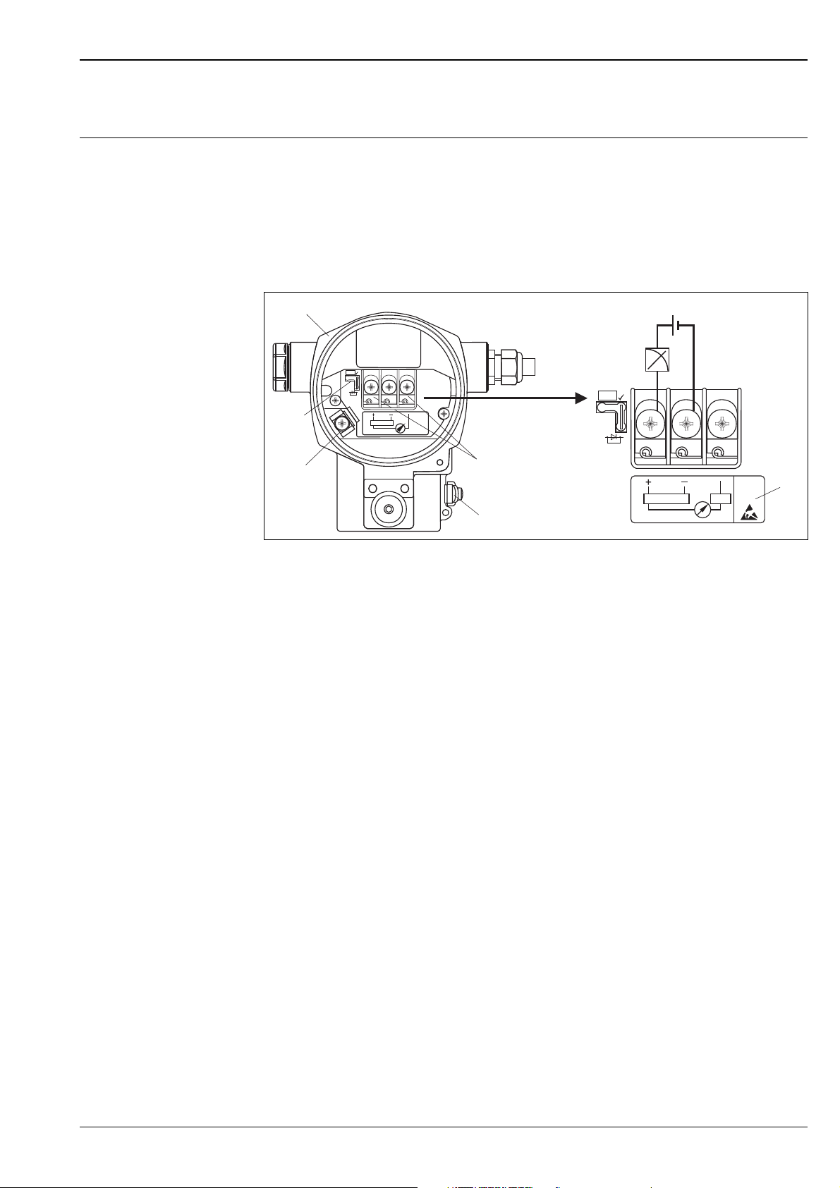
Electrical connection Note!
• When using the measuring device in hazardous areas, installation must comply with the corresponding
national standards and regulations and the Safety Instructions or Installation or Control Drawings. ä 82,
section "Safety Instructions" and "Installation/Control Drawings".
• Devices with integrated overvoltage protection must be earthed. ä 28.
• Protective circuits against reverse polarity, HF influences and overvoltage peaks are installed.
4...20 mA HART
P01-xMx7xxxx-04-xx-xx-xx-001
Electrical connection 4...20 mA HART
1 Housing
2 Jumper for 4...20 mA test signal. ä 17, section "Taking 4...20 mA test signal" .
3 Internal earth terminal
4 External earth terminal
5 4...20 mA test signal between positive and test terminal
6 minimum supply voltage = 10.5 V DC, jumper is inserted in accordance with the illustration.
7 minimum supply voltage = 11.5 V DC, jumper is inserted in "Test" position.
8 Devices with integrated overvoltage protection are labelled OVP (overvoltage protection) here ( ä 28).
PROFIBUS PA
The digital communication signal is transmitted to the bus via a 2-wire connection. The bus also provides the
auxiliary energy. For further information on the network structure and grounding and for further bus system
components such as bus cables, see the relevant documentation, e.g. Operating Instructions BA034S
"Guidelines for planning and commissioning PROFIBUS DP/PA" and the PNO Guideline.
Cable specifications:
• Use a twisted, shielded two-wire cable, preferably cable type A
Note!
For further information on the cable specifications, see Operating Instructions BA034S
Guidelines for planning and commissioning PROFIBUS DP/PA", PNO Guideline 2.092 "
PROFIBUS PA User and Installation Guideline" and IEC 61158-2 (MBP).
Endress+Hauser 15
Deltabar S
Han7D
–
+
+–
–
+
1
5
4
6
7
8
2
3
M12
–
+
+–
–
+
FOUNDATION Fieldbus
The digital communication signal is transmitted to the bus via a 2-wire connection. The bus also provides the
auxiliary energy. For further information on the network structure and grounding and for further bus system
components such as bus cables, see the relevant documentation, e.g. Operating Instructions BA013S
"FOUNDATION Fieldbus Overview" and the FOUNDATION Fieldbus Guideline.
Cable specifications:
• Use a twisted, shielded two-wire cable, preferably cable type A
Note!
For further information on the cable specifications, see Operating Instructions BA013S "FOUNDATION
Fieldbus Overview", FOUNDATION Fieldbus Guideline and IEC 61158-2 (MBP).
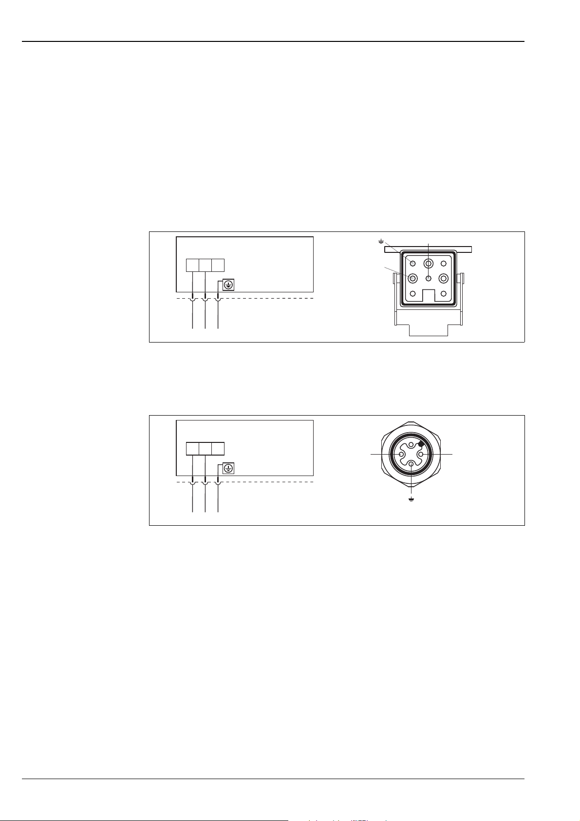
Devices with Harting plug Han7D
Left: electrical connection for devices with Harting plug Han7D
Right: view of the plug connector at the device
Devices with M12 plug
Left: electrical connection for devices with M12 plug
Right: view of the plug at the device
Endress+Hauser offers for devices with M12 plug the following accessories:
Plug-in jack M 12x1, straight
• Material: Body PA; coupling nut CuZn, nickel-plated
• Degree of protection (fully locked): IP67
• Order number: 52006263
Plug-in jack M 12x1, elbowed
• Material: Body PBT/PA; coupling nut GD-Zn, nickel-plated
• Degree of protection (fully locked): IP67
• Order number: 51006327
2
Cable 4x0.34 mm
• Material: Body PUR; coupling nut CuSn/Ni; cable PVC
• Degree of protection (fully locked): IP67
• Order number: 52010285
with M12 socket, elbowed, screw plug, 5 m length
P01-xMD7xxxx-04-xx-xx-xx-000
P01-xMD7xxxx-04-xx-xx-xx-008
16 Endress+Hauser
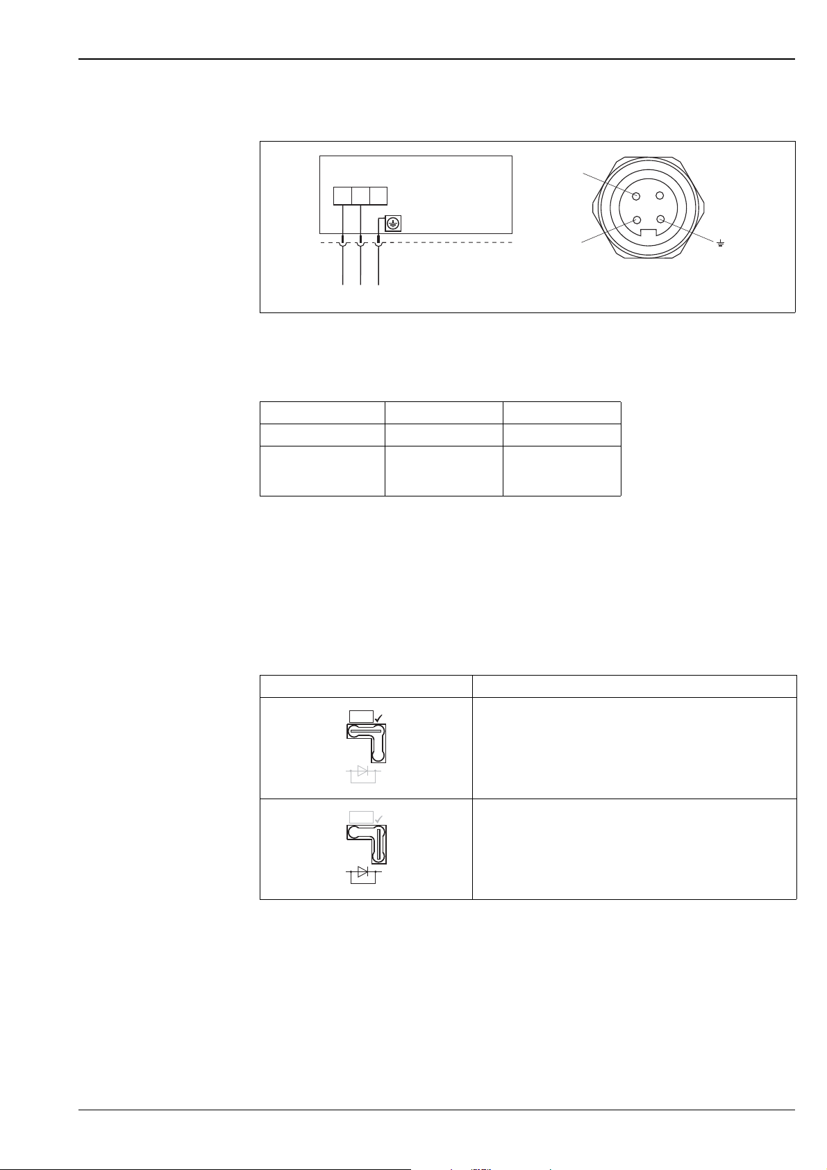
Deltabar S
–
+
7/8”
–
+
+–
Test
TestTest
Devices with 7/8" plug
Left: electrical connection for devices with 7/8" plug
Right: view of the plug at the device
Kabel gland
Approval Typ Clamping range
Standard, II1/2G Exia, IS Plastic M20x1.5 5...10 mm
ATEX II1/2D, II1/3D,
II1/2GD Exia, II1GD Exia
II3G Ex nA
Metal M20x1.5 (Ex e) 7...10.5 mm
P01-xxx7xxxx-04-xx-xx-xx-003
Terminals
for wire cross-sections of 0.5 to 2.5 mm
2
Taking 4...20 mA test signal
A 4...20 mA signal may be measured via the positive and test terminal without interrupting the measurement.
The minimum supply voltage of the device can be reduced by simply changing the position of the jumper. As
a result, operation is also possible with lower voltage sources. Observe the position of the jumper in accordance
with the following table.
Jumper position for test signal Description
– Taking 4...20 mA test signal via plus and test terminal:
possible. (Thus, the output current can be measured without
interruption via the diode.)
– Delivery status
– minimum supply voltage: 11.5 V DC
– Taking 4...20 mA test signal via plus and test terminal:
not possible.
– minimum supply voltage: 10.5 V DC
Endress+Hauser 17

Supply voltage Note!
• When using the measuring device in hazardous areas, installation must comply with the corresponding
national standards and regulations and the Safety Instructions or Installation or Control Drawings.
• All explosion protection data are given in separate documentation which is available upon request. The Ex
documentation is supplied as standard with all devices approved for use in explosion hazardous areas.
ä 82, sections "Safety Instructions" and "Installation/Control Drawings".
4...20 mA HART
• Version for non-hazardous areas, jumper for 4...20 mA test signal in "Test" position (delivery status):
11.5...45 V DC
• Version for non-hazardous areas, jumper for 4...20 mA test signal in "Non-test" position: 10.5...45 V DC
PROFIBUS PA
• Version for non-hazardous areas: 9...32 V DC
FOUNDATION Fieldbus
• Version for non-hazardous areas: 9...32 V DC
Current consumption • PROFIBUS PA: 13 mA ± 1 mA, switch-on current corresponds to IEC 61158-2, Clause 21
• FOUNDATION Fieldbus: 15 mA ± 1 mA, switch-on current corresponds to IEC 61158-2, Clause 21
Deltabar S
Cable entry ä 67 ff, feature 30 "Housing, Cable entry, Protection".
Cable specification • Endress+Hauser recommends using shielded, twisted-pair two-wire cables.
• Terminals for wire cross-sections 0.5...2.5 mm
2
• Cable external diameter: 5...9 mm
Residual ripple Without influence on 4...20 mA signal up to 5 % residual ripple within the permitted voltage range [according
to HART hardware specification HCF_SPEC-54 (DIN IEC 60381-1)]
Influence of power supply 0.0006% of URL/1 V
18 Endress+Hauser

Deltabar S
Performance characteristics – general
Reference operating conditions
Long-term stability
• As per IEC 60770
• Ambient temperature T
= constant, in the range of: +21...+33°C (+69.8...+91.4°F)
U
• Humidity = constant, in the range of: 5...80 % r.H
• Ambient pressure pU = constant, in the range of: 860...1060 mbar
• Position of the measuring cell: constant, in the range of: 1°
• Input of LOW SENSOR TRIM and HIGH SENSOR TRIM for lower range value and upper range value
• Zero based span
• Material of the process isolating diaphragm
– PMD75: AISI 316L/1.4435, Alloy C276, Gold-Rhodium coated, Monel
– FMD77, FMD78: AISI 316L/1.4435
– PMD70, FMD76: Al
(Aluminium-oxide-ceramic)
2O3
• Filling oil: silicone oil
• Side flanges material PMD75: AISI 316L/1.4435
• Supply voltage: 24 V DC ± 3 V DC
• Load with HART: 250
1 year 5 years 10 year
Measuring range [mbar] % of URL
10 ±0.150 -- --
100 ±0.180 -- --
500 ±0.025 ±0.050 ±0.075
3000 ±0.038 ±0.075 ±0.150
16000 ±0.025 ±0.110 ±0.210
Influence of the installation position
Vibration effects
• PMD70, FMD76: 3 mbar
• PMD75: 4 mbar
1, 3
• FMD77: 32 mbar
1) Device is rotated vertically to the axis of the process isolating diaphragm.
2) Device rotated vertically to the process isolating diaphragm of the flange .
3) The value is doubled for devices with inert oil.
1, 3
2, 3
Note!
Position-dependent zero shift can be corrected. ä 23, section "General installation instructions" and
ä 62 ff, section "Response time".
Device Housing Test standard Vibration effects
PMD70/
FMD76
PMD75 optional on-site display on
PMD75 optional on-site display on
optional on-site display on
the side (T14)
the side (T14)
the top (T15)
GL reference accuracy to
10...18 Hz: ±4 mm;
18...500 Hz: 5 g
reference accuracy to
10...38 Hz: ±0.35 mm;
IEC 61298-3
38...2000 Hz: 2 g
reference accuracy to
10...60 Hz: ±0.35 mm;
60...2000 Hz: 5 g
Endress+Hauser 19

Deltabar S
Performance characteristics – metallic process isolating diaphragms
Reference accuracy –
PMD75, FMD77, FMD78
The reference accuracy comprises the non-linearity according to limit point setting, hysteresis and
non-reproducibility as per IEC 60770. The data refer to the calibrated span.
The following applies for the root-extracting characteristic curve:
The accuracy data of the Deltabar S is taken into the accuracy calculation of the flow rate with a factor of 0.5.
PMD75
Measuring cell % of the set span
10 mbar, 30 mbar
100 mbar
500 mbar
Platinum version:
00 mbar
• TD 1:1
• TD > 1:1
• TD 1:1 to TD 4:1
•TD > 4:1
• TD 1:1 to TD 15:1
•TD > 15:1
•TD 1:1 = ±0.05
==±0.15
±0.15 x TD
==±0.075
(0.012 x TD + 0.027)
==±0.075
(0.0015 x TD + 0.053)
FMD77, FMD78
Measuring
cell
100 mbar
500 mbar,
3 bar, 16 bar
40 bar
• TD 1:1 to TD 4:1
• TD > 4:1
• TD 1:1 to TD 15:1
•TD > 15:1
FMD77 FMD78
% of the set span (influence of the diaphragm seal included)
==±0.15
(0.03 x TD + 0.03)
==±0.075
(0.0015 x TD + 0.053)
• TD 1:1 to TD 4:1
• TD > 4:1
• TD 1:1 to TD 4:1
•TD > 4:1
• TD 1:1 to TD 4:1
•TD > 4:1
==±0.15
(0.03 x TD + 0.03)
==±0.15
(0.02 x TD + 0.07)
==±0.15
(0.02 x TD + 0.07)
Total performance – PMD75 The "Total performance" specification comprises the non-linearity including hysteresis, non-reproducibility, the
thermal change of the zero point as well as the influence of the line pressure (p
Measuring cell AISI 316L/1.4435, Alloy, Gold-Rhodium
or Monel process isolating diaphragm
% of the set span
500 mbar to TD 2:1 0.15 0.30
All specifications apply to the temperature range –10...+60°C (+14...+140°F).
Tantal process isolating diaphragm
= 70 bar).
st
Total Error The total error comprises the long-term stability and the total performance:
Measuring cell AISI 316L/1.4435, Alloy, Gold-Rhodium
10 mbar, 30 mbar,
100 mbar
500 mbar 0.20 0.35
or Monel process isolating diaphragm
% of URL/year
0.33 0.48
Tantal process isolating diaphragm
20 Endress+Hauser

Deltabar S
Warm-up period –
PMD75, FMD77, FMD78
Influence of the operating pressure on zero point and span – PMD75, FMD77, FMD78
Thermal change of the zero
output and the output
span -- PMD75
• 4...20 mA HART : < 10 s
• PROFIBUS PA: 6 s
• FOUNDATION Fieldbus: 50 s
Measuring
cell
10 mbar 0.15 % of URL/7 bar 0.035 % of URL/7 bar 0.28 % of URL/7 bar 0.28 % of URL/7 bar
30 mbar 0.35 % of URL/70 bar 0.14 % of URL/70 bar 0.70 % of URL/70 bar 0.70 % of URL/70 bar
100 mbar 0.15 % of URL/70 bar 0.14 % of URL/70 bar 0.42 % of URL/70 bar 0.42 % of URL/70 bar
500 mbar 0.075 % of URL/70 bar 0.14 % of URL/70 bar 0.14 % of URL/70 bar 0.14 % of URL/70 bar
3 bar 0.075 % of URL/70 bar 0.14 % of URL/70 bar 0.14 % of URL/70 bar 0.14 % of URL/70 bar
16 bar 0.075 % of URL/70 bar 0.14 % of URL/70 bar 0.14 % of URL/70 bar 0.14 % of URL/70 bar
40 bar 0.075 % of URL/70 bar 0.14 % of URL/70 bar 0.14 % of URL/70 bar 0.14 % of URL/70 bar
AISI 316L/1.4435, Alloy, Gold-Rhodium
coated or Monel process isolating diaphragm
Influence of the
operating pressure on
the zero point
Influence of the
operating pressure on
the span
Tantal process isolating diaphragm
Influence of the
operating pressure on
the zero point
Influence of the
operating pressure on
the span
Note!
The influence of the operating pressure on the zero point can be calibrated out.
Measuring cell –10...+60 °C (+14...+140°F)
AISI 316L/1.4435, Alloy, Gold-Rhodium
coated or Monel process isolating
diaphragm
% of the set span
10 mbar, 30 mbar (0.31 x TD + 0.06)
100 mbar (0.18 x TD + 0.02) (0.24 x TD + 0.06)
500 mbar, 3 bar (0.08 x TD + 0.05)
16 bar (0.1 x TD + 0.1)
40 bar (0.08 x TD + 0.05)
Tantal process isolating diaphragm
Measuring cell –40...-10 °C, +60...+85 °C
10 mbar, 30 mbar (0.45 x TD + 0.1)
100 mbar (0.3 x TD + 0.15)
500 mbar, 3 bar (0.12 x TD + 0.1)
16 bar (0.15 x TD + 0.2)
40 bar (0.37 x TD + 0.1)
(–40...+14°F, +140...+185°F)
all process isolating diaphragm materials
% of the set span
Endress+Hauser 21

Deltabar S
Performance characteristics – ceramic process isolating diaphragms
Reference accuracy –
PMD70, FMD76
Total performance –
PMD70, FMD76
The reference accuracy comprises the non-linearity including hysteresis and non-reproducibility in accordance
with the limit point method as per IEC 60770. The data refer to the calibrated span.
The following applies for the root-extracting characteristic curve:
The accuracy data of the Deltabar S is taken into the accuracy calculation of the flow rate with a factor of 0.5.
Measuring cell % of the set span
25 mbar
100 mbar
500 mbar, 3 bar
Platinum version: 100 mbar, 500 mbar, 3 bar • TD 1:1 = ±0.05
•TD 1:1
• TD > 1:1
• TD 1:1 to TD 4:1
•TD > 4:1
• TD 1:1 to TD 15:1
•TD > 15:1
==±0.15
±0.15 x TD
==±0.075
(0.012 x TD + 0.027)
==±0.075
(0.0015 x TD + 0.05252)
The "Total performance" specification comprises the non-linearity including hysteresis, non-reproducibility, the
thermal change of the zero point as well as the influence of the line pressure (p
Measuring cell % of the set span
500 mbar to TD 1:1 • 0.15
All specifications apply to the temperature range –10...+60°C (+14...+140°F).
= 70 bar).
st
Total Error The total error comprises the long-term stability and the total performance:
Measuring cell % of URL/year
25 mbar, 100 mbar • 0.33
500 mbar, 3 bar • 0.20
Warm-up period –
PMD70, FMD76
• 4...20 mA HART : < 10 s
• PROFIBUS PA: 6 s
• FOUNDATION Fieldbus: 50 s
Influence of the operating pressure on zero point and span – PMD70, FMD76
Measuring cell Influence of the operating pressure on the
zero point
25 mbar 0.7 % of URL/7 bar 0.14 % of URL/7 bar
100 mbar 0.175 % of URL/70 bar 0.14 % of URL/70 bar
500 mbar 0.075 % of URL/70 bar 0.14 % of URL/70 bar
3 bar 0.075 % of URL/70 bar 0.14 % of URL/70 bar
Influence of the operating pressure on the
span
Note!
The influence of the operating pressure on the zero point can be calibrated out.
Thermal change of the zero
output and the output span –
PMD70, FMD76
Measuring cell –10...+60 °C
(+14...+140°F)
% of the set span
25 mbar (0.35 x TD + 0.05) (0.3 x TD + 0.15)
100 mbar (0.05 x TD + 0.05) (0.08 x TD + 0.07)
–20...–10 °C, +60...+85 °C
(–4...+14°F, +140...+185°F)
22 Endress+Hauser

Deltabar S
Operating conditions (Installation)
General installation instructions
Measuring arrangement Flow measurement
• The position-dependent zero shift can be corrected directly at the device via operating key, for devices with
external operation even in hazardous areas. Diaphragm seals also shift the zero point, depending on the
installation position ( ä 64 ff, "Installation instructions").
• The housing of the Deltabar S can be rotated up to 380°. ä 26, section "Turn the housing".
• Endress+Hauser offers a mounting bracket for installing the device on pipes or walls. ä 24, section "Wall-
and pipe-mounting".
• When measuring in media with solid proportions, such as dirty liquids, installing separators and drain valves
is useful for capturing and removing sediment.
• Using a three-valve or five-valve manifold allows for easy commissioning, installation and maintenance
without interrupting the process.
• General recommendations for the impulse piping can be found in DIN 19210 "Methods for measurement of
fluid flow; differential piping for flow measurement devices" or the corresponding national or international
standards.
• Install the impulse piping with a continuous gradient of at least 10%.
• When routing the impulse piping outdoors, ensure that sufficient anti-freeze protection is used, e.g. by using
pipe heat tracing.
• For FMD77 and FMD78: See page 64 ff, "Installation instructions, Diaphragm seal systems" section.
• The PMD70 and PMD75 are best suited to flow measurement.
• Measuring arrangement for gases: Mount device above the measuring point.
• Measuring arrangement for liquids and vapours: Mount device below tapping point.
• For flow measurement in vapours, mount the condensate traps at the same level as the same the tapping
point and at the same distance from Deltabar S.
Level measurement
• PMD70, PMD75, FMD76 and FMD77 are best suited to level measurement in open tanks. All Deltabar S
devices are suitable for level measurement in closed tanks.
Measuring arrangement level measurement in open tanks
• PMD70, PMD75: Mount device below the lower measuring connection. The negative side is open to
atmosphere pressure.
• FMD76, FMD77: Mount device direct on the tank. The negative side is open to atmosphere pressure.
Measuring arrangement level measurement in closed tanks and closed tanks with superimposed vapour
• PMD70, PMD75: Mount device below the lower measuring connection. Always connect the negative side
above the maximum level.
• FMD76, FMD77: Mount device direct on the tank. Always connect the negative side above the maximum
level.
• In the case of level measurement in closed tanks with superimposed vapour, a condensate trap ensures
pressure which remains constant on the minus side.
Pressure measurement
• The PMD70 and PMD75 are best suited to differential pressure measurement.
• Measuring arrangement for gases: Mount device above the measuring point.
• Measuring arrangement for liquids and steams: Mount device below tapping point.
• For differential pressure measurement in vapour, mount the condensate traps at the same level as the same
the tapping point and at the same distance from Deltabar S.
Endress+Hauser 23
Deltabar S
λ 0.04≤
W
mK•
T
A
T
P
106
74
74
124
135
37.5
➀
Heat insulation – FMD77 The FMD77 must only be insulated up to a certain height. The maximum permitted insulation height is labelled
on the devices and applies to an insulation material with a heat conductivity
0.04 W/(m x K) and to the maximum permitted ambient and process temperature ( see table below). The
data were determined under the most critical application "quiescent air".
P01-FMD77xxxx-11-xx-xx-xx-000
Maximum permitted insulation height
FMD77
Ambient temperature (T
) 70°C (158°F)
A
Process temperature (TP) max. 400°C (752°F), depending on the
diaphragm seal filling oil used ( see
page 59)
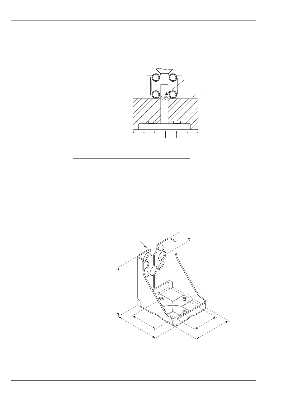
Wall- and pipe-mounting Endress+Hauser offers a mounting bracket for installing the device on pipes or walls. ä 67 ff, feature 110,
"Additional options 2".
Note!
If a valve block is used, its dimensions should also be taken into consideration.
P01-xMD7xxxx-11-xx-xx-xx-008
Mounting bracket for wall and pipe-mounting
A bracket including mounting accessories for pipe mounting is included with the device.
1 Device mounting
24 Endress+Hauser
Deltabar S
➀
➁
➂
➃
r ³ 120 mm
IP xx
(see chapter
“Ordering information”)
FEP cable:
IP 69K
IP 66/68 NEMA 4/6P
PE cable:
IP 66/68 NEMA 4/6P
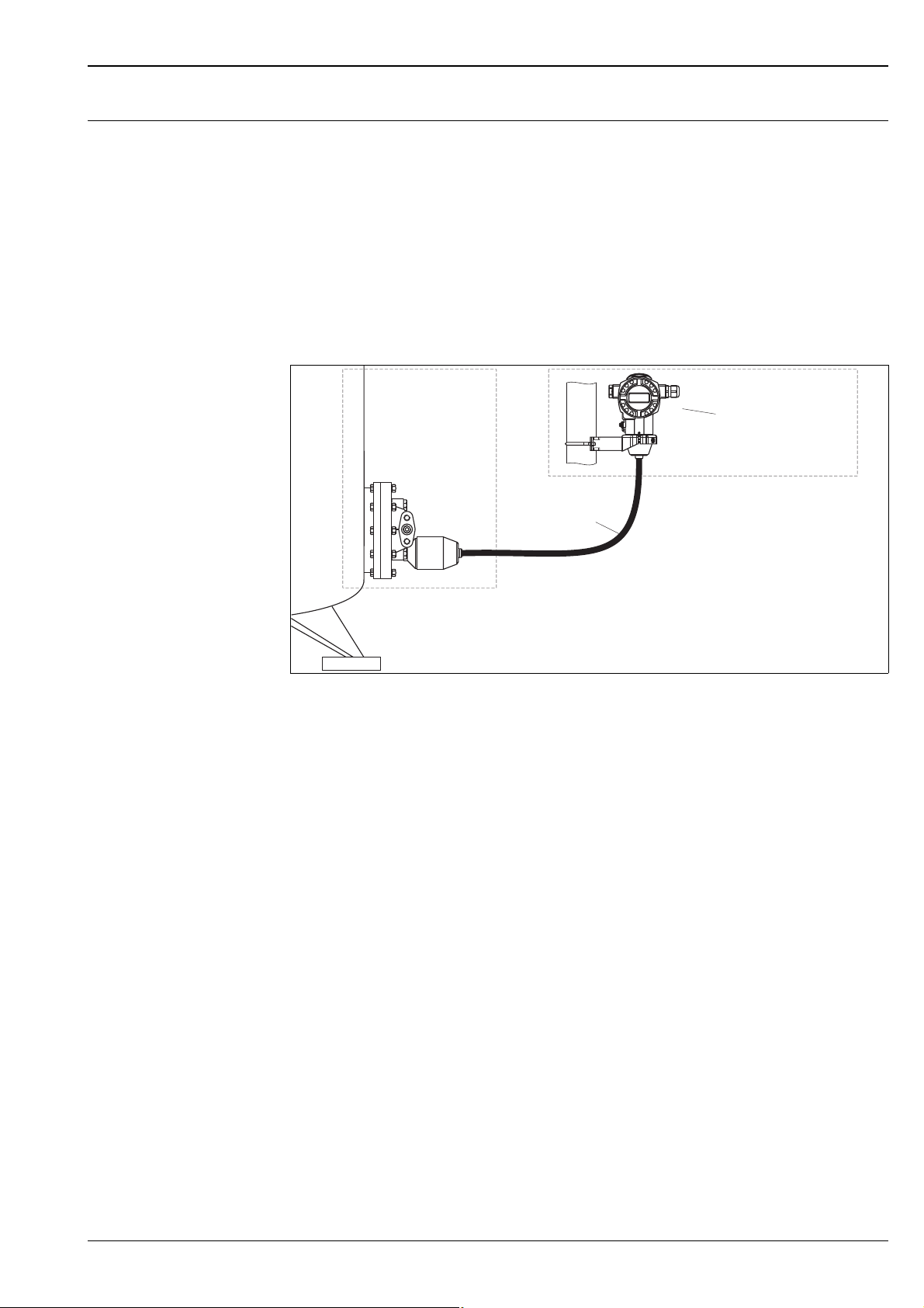
"Separate housing" version With the "separate housing" version, you are able to mount the housing with the electronics insert at a distance
from the measuring point. This facilitates trouble-free measurement:
• Under particularly difficult measuring conditions (at installation locations that are cramped or difficult to
access)
• If rapid cleaning of the measuring point is required
• If the measuring point is exposed to vibrations.
You can choose between different cable versions:
• PE (2 m, 5 m and 10 m)
• FEP (5 m).
ä 68 ff, Feature 110, "Additional options 2", Version "G".
For the dimensions, see ä 50.
P01-xMD7xxxx-11-xx-xx-en-010
In the case of the "separate housing" version, the sensor is delivered with the process connection and cable ready
mounted. The housing and a mounting bracket are enclosed as separate units. The cable is provided with a socket at both
ends. These sockets are simply connected to the housing and the sensor.
1 Process connection with sensor
2 Cable, both ends are fitted with a socket
3 Mounting bracket provided, suitable for pipe and wall mounting
4 Housing with electronic insert
Degree of protection for the process connection with sensor with the use of
• FEP cable:
– IP 69K
– IP 66 NEMA 4/6P
– IP 68 (1.83 mH
O for 24 h) NEMA 4/6P
2
• PE cable:
– IP 66 NEMA 4/6P
– IP 68 (1.83 mH
O for 24 h) NEMA 4/6P
2
Technical data of the PE and FEP cable:
• Minimum bending radius: 120 mm (4.72 inch)
• Cable extraction force: max. 450 N
• Resistance to UV light
Use in hazardous area:
• Intrinsically safe installations (Ex ia/IS)
• FM/CSA IS: for Div.1 installatin only
Endress+Hauser 25
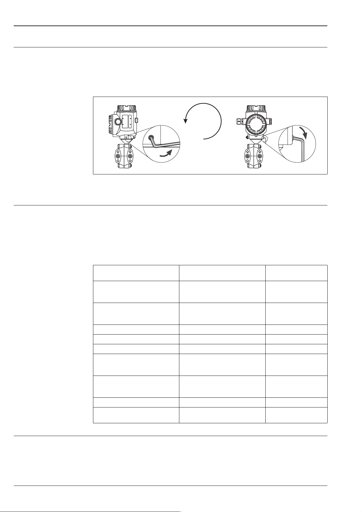
Turn the housing The housing can be rotated up to 380° by loosening the Allen screw.
max. 380°
Your benefits
• Simple mounting by optimally aligning the housing
• Good, accessible device operation
• Optimum readability of the on-site display (optional).
Align the housing by loosening the Allen screw.
T14 and T15 housing: 2 mm Allen key; T17 housing: 3 mm Allen key
Deltabar S
P01-xMD7xxxx-17-xx-xx-xx-001
Oxygen applications Oxygen and other gases can react explosively to oils, grease and plastics, such that, among other things, the
following precautions must be taken:
– All components of the system, such as measuring devices, must be cleaned in accordance with the BAM
(DIN 19247) requirements.
– Dependent on the materials used, a certain maximum temperature and a maximum pressure for oxygen
applications must not be exceeded.
The devices suitable for gaseous oxygen applications are listed in the following table with the specification p
Order code for devices cleaned for
oxygen applications
PMD70 – ********2**,
Devices with 500 mbar or 3000 mbar
measuring cell
PMD70 – ********2**,
Devices with 25 mbar or 100 mbar
measuring cell
PMD75 – * * * ** * * * K * * 160 bar
PMD75 – * * * ** * * * 2 * * 160 bar 60°C (140°F)
PMD75 – * * * ** * * * 3 * * 160 bar 60°C (140°F)
FMD76 – ******T***,
Devices with 500 mbar or 3000 mbar
measuring cell
FMD76 – ******T***,
Devices with 25 mbar or 100 mbar
measuring cell
FMD77 – *****T*F** PN of the flange 60°C (140°F)
FMD78 – ********4**
FMD78 – ********D**
p
for oxygen applications T
max
30 bar 60°C (140°F)
PN of the flange 60°C (140°F)
30 bar 60°C (140°F)
PN of the measuring cell 60°C (140°F)
90 bar 85°C (185°F)
for oxygen
max
applications
85°C (185°F)
max
.
Ultra pure gas applications Endress+Hauser also offers devices for special applications, such as ultra pure gas, cleaned from oil and grease.
No special restrictions regarding the process conditions apply to these devices.
ä 67 ff, PMD70 and PMD75: feature 80 "Seal", FMD76 and FMD77: feature 70 "Process connection low-
pressure side, material, seal".
26 Endress+Hauser
 Loading...