

Page 1
BA01044P/00/EN/06.17
71376028
Valid as of version
01.00.00
Products Solutions Services
Operating Instructions
Deltabar FMD71, FMD72
Level measurement with electronic differential pressure
Electronic differential pressure transmitter with ceramic
and metal sensors
Page 2
Deltabar FMD71, FMD72
Order code:
Ext. ord. cd.:
Ser. no.:
www.endress.com/deviceviewer
Endress+Hauser
Operations App
XXXXXXXXXXXX
XXXXX-XXXXXX
XXX.XXXX.XX
Serial number
1.
3.
2.
A0023555
• Make sure the document is stored in a safe place such that it is always available when
working on or with the device.
• To avoid danger to individuals or the facility, read the "Basic safety instructions" section
carefully, as well as all other safety instructions in the document that are specific to
working procedures.
• The manufacturer reserves the right to modify technical data without prior notice. Your
Endress+Hauser distributor will supply you with current information and updates to
these Instructions.
2 Endress+Hauser
Page 3

Deltabar FMD71, FMD72 Table of contents
Table of contents
1 Document information .............. 5
1.1 Document function ..................... 5
1.2 Symbols used .......................... 5
1.3 Documentation ........................ 6
1.4 Terms and abbreviations ................. 8
1.5 Turn down calculation ................... 9
1.6 Registered trademarks ................... 9
2 Basic safety instructions ........... 10
2.1 Requirements concerning the staff ......... 10
2.2 Designated use ....................... 10
2.3 Workplace safety ...................... 11
2.4 Operational safety ..................... 11
2.5 Product safety ........................ 11
3 Product description ................ 12
3.1 Product design ........................ 12
3.2 Function ............................ 13
4 Incoming acceptance and product
identification ..................... 14
4.1 Incoming acceptance ................... 14
4.2 Product identification ................... 15
4.3 Nameplates .......................... 15
4.4 Storage and transport .................. 17
5 Installation ....................... 18
5.1 Mounting dimensions .................. 18
5.2 Mounting location ..................... 18
5.3 Orientation .......................... 18
5.4 General installation instructions ........... 18
5.5 Thermal insulation - FMD71 high-
temperature version .................... 19
5.6 Installing the sensor modules ............. 20
5.7 Mounting sensor modules with PVDF
installation coupling ................... 20
5.8 Installing the transmitter ................ 21
5.9 Closing the housing cover ................ 22
5.10 Seal for flange mounting ................ 23
5.11 Post-installation check .................. 23
6 Electrical connection .............. 24
6.1 Connecting the sensor module LP to the
sensor module HP ..................... 24
6.2 Connecting the sensor module HP to the
transmitter .......................... 25
6.3 Connecting the measuring unit ............ 26
6.4 Connection conditions .................. 27
6.5 Connection data ....................... 28
6.6 Post-connection check .................. 29
7 Operation options ................. 30
7.1 Operation without operating menu ......... 30
7.2 Operation with an operating menu ......... 32
7.3 Structure of the operating menu ........... 32
7.4 Operating options ..................... 33
7.5 Operating the device using onsite display
(optional) ........................... 33
7.6 Operation using Endress+Hauser operating
program ............................ 36
7.7 Direct access to parameters .............. 37
7.8 Locking/unlocking operation ............. 37
7.9 Resetting to factory settings (reset) ........ 38
8
Integrating transmitter via HART
®
protocol .......................... 40
8.1 HART process variables and measured
values .............................. 40
8.2 Device variables and measured values ....... 41
9 Commissioning .................... 42
9.1 Post-installation check and function check ... 42
9.2 Unlocking/locking configuration .......... 42
9.3 Commissioning without an operating menu .. 42
9.4 Commissioning with an operating menu ..... 45
9.5 Language selection .................... 45
9.6 Measuring mode selection ............... 46
9.7 Selecting the high-pressure side ........... 46
9.8 Pressure unit selection .................. 47
9.9 Pos. zero adjust ....................... 47
9.10 Configuring level measurement ........... 48
9.11 Linearization ......................... 58
9.12 Configuring pressure measurement ........ 61
9.13 Backing up or duplicating the device data .... 63
9.14 Configuring the local display ............. 64
9.15 Protecting settings from unauthorized
access .............................. 64
10 Diagnostics and troubleshooting ... 65
10.1 Troubleshooting ...................... 65
10.2 Diagnostic events ...................... 65
10.3 Response of output to errors .............. 69
10.4 Firmware history ...................... 70
10.5 Disposal ............................ 70
11 Maintenance ...................... 71
11.1 Information on cleaning ................. 71
11.2 Exterior cleaning ...................... 71
12 Repairs ........................... 72
12.1 General notes ........................ 72
12.2 Spare parts .......................... 73
Endress+Hauser 3
Page 4

Table of contents Deltabar FMD71, FMD72
12.3 Return .............................. 73
13 Overview of the operating menu .... 74
14 Description of Device Parameters ... 78
14.1 Language ........................... 78
14.2 Display/operat. ....................... 78
14.3 Setup .............................. 80
14.4 Setup → Extended Setup ................. 85
14.5 Setup → Extended Setup → Level ("Level"
measuring mode) ...................... 86
14.6 Setup → Extended Setup → Linearization .... 91
14.7 Setup → Extended Setup → Current output ... 93
14.8 Diagnostics .......................... 97
14.9 Diagnosis → Sensor HP .................. 97
14.10 Diagnosis → Sensor LP .................. 99
14.11 Diagnostic → Diagnostic list ............. 100
14.12 Diagnosis → Event logbook .............. 100
14.13 Diagnosis → Instrument info ............ 101
14.14 Diagnosis → Sens. limit HP .............. 104
14.15 Diagnosis → Sens. limit LP .............. 104
14.16 Diagnosis → Measured Values ........... 105
14.17 Diagnosis → Simulation ................ 107
14.18 Diagnosis → Reset .................... 110
15 Technical data ................... 112
15.1 Input .............................. 112
15.2 Output ............................ 115
15.3 Performance characteristics of ceramic
process isolating diaphragm ............. 118
15.4 Performance characteristics of metallic
process isolating diaphragm ............. 123
15.5 Environment ........................ 128
15.6 Process ............................ 129
15.7 Additional technical data ............... 130
Index ................................. 131
4 Endress+Hauser
Page 5
Deltabar FMD71, FMD72 Document information
DANGER
WARNING
CAUTION
NOTICE
1 Document information
1.1 Document function
These Operating Instructions contain all the information that is required in various phases
of the life cycle of the device: from product identification, incoming acceptance and
storage, to mounting, connection, operation and commissioning through to
troubleshooting, maintenance and disposal.
1.2 Symbols used
1.2.1 Safety symbols
Symbol Meaning
DANGER!
This symbol alerts you to a dangerous situation. Failure to avoid this situation will
result in serious or fatal injury.
WARNING!
This symbol alerts you to a dangerous situation. Failure to avoid this situation can
result in serious or fatal injury.
CAUTION!
This symbol alerts you to a dangerous situation. Failure to avoid this situation can
result in minor or medium injury.
NOTE!
This symbol contains information on procedures and other facts which do not result in
personal injury.
1.2.2 Electrical symbols
Symbol Meaning
Direct current
Alternating current
Direct current and alternating current
Ground connection
A grounded terminal which, as far as the operator is concerned, is grounded via a
grounding system.
Protective Earth (PE)
A terminal which must be connected to ground prior to establishing any other
connections.
The ground terminals are situated inside and outside the device:
• Inner ground terminal: Connects the protectiv earth to the mains supply.
• Outer ground terminal: Connects the device to the plant grounding system.
1.2.3 Tool symbols
Symbol Meaning
Flat blade screwdriver
A0011220
Phillips head screwdriver
A0011219
Endress+Hauser 5
Page 6

Document information Deltabar FMD71, FMD72
A
,…,
1.
2.
3.
Symbol Meaning
Allen key
A0011221
Open-ended wrench
A0011222
1.2.4 Symbols for certain types of information
Symbol Meaning
Permitted
Procedures, processes or actions that are permitted.
Preferred
Procedures, processes or actions that are preferred.
Forbidden
Procedures, processes or actions that are forbidden.
Tip
Indicates additional information.
Reference to documentation
Reference to page
Reference to graphic
Visual inspection
1.2.5 Symbols in graphics
Symbol Meaning
1, 2, 3 ... Item numbers
Series of steps
A, B, C, ... Views
A-A, B-B, C-C, ... Sections
1.3 Documentation
The document types listed are available:
In the Download Area of the Endress+Hauser Internet site: www.endress.com →
Download
1.3.1 Technical Information (TI): planning aid for your device
TI01033P:
The document contains all the technical data on the device and provides an overview of
the accessories and other products that can be ordered for the device.
1.3.2 Brief Operating Instructions (KA): getting the 1st measured value quickly
KA01105P:
6 Endress+Hauser
Page 7
Deltabar FMD71, FMD72 Document information
The Brief Operating Instructions contain all the essential information from incoming
acceptance to initial commissioning.
1.3.3 Description of Device Parameters (GP): reference for your parameters
GP01013P:
The document provides a detailed explanation of each individual parameter in the
operating menu. The description is aimed at those who work with the device over the
entire life cycle and perform specific configurations.
1.3.4 Safety Instructions (XA)
Safety Instructions (XA) are supplied with the device depending on the approval. These
instructions are an integral part of the Operating Instructions.
Device Directive Documentation Option
FMD71, FMD72 ATEX II 1/2G Ex ia IIC T6 Ga/Gb XA00619P BA
FMD71, FMD72 ATEX II 1/2G Ex d [ia] IIC T6 Ga/Gb XA00620P BC
FMD71, FMD72 ATEX II 3G Ex nA IIC T6 GC XA00621P BD
FMD71, FMD72 IEC Ex ia IIC T6 Ga/Gb XA00622P IA
FMD71, FMD72 IEC Ex d [ia] IIC T6 Ga/Gb XA00623P IB
FMD71, FMD72 CSA General Purpose - CD
FMD71, FMD72 NEPSI Ex ia IIC T4/T6 Ga/Gb XA01352P NA
FMD71, FMD72 NEPSI Ex d [ia] IIC T4/T6 Ga/Gb XA01353P NB
FMD71, FMD72 INMETRO Ex ia IIC T6...T4 Ga/Gb XA01378P MA
FMD71, FMD72 INMETRO Ex d [ia] IIC T6...T4 Ga/Gb XA01379P MC
FMD71, FMD72 EAC Ga/Gb Ex ia IIC T6...T4 XA01594P GA
FMD71, FMD72 EAC Ga/Gb Ex d [ia] IIC T6...T4 X XA01595P GB
FMD71 FM C/US IS Cl.I Div.1 Gr.A-D, AEx ia, Zone 0,1,2 XA00628P FA
FMD71 FM C/US XP AIS Cl.I Div.1 Gr.A-D, Exd [ia] Zone 0,1,2 XA00629P FB
FMD71 CSA C/US XP Cl.I Div.1 Gr.A-D, Ex d [ia], Zone 0,1,2 XA00631P CB
FMD71 FM C/US NI Cl.I Div.2 Gr.A-D, Zone 2 XA00668P FD
FMD71 CSA C/US NI, Cl.I Div. 2, Gr.A-D Cl.I, Zone 2, IIC XA00670P CC
FMD71 CSA C/US IS Cl.I Div.1 Gr.A-D, Ex ia Zone 0,1,2 XA00630P CA
FMD72 CSA C/US IS Cl.I Div.1 Gr.A-D, Ex ia Zone 0,1,2 XA00626P CA
FMD72 CSA C/US XP Cl.I Div.1 Gr.A-D, Ex d [ia], Zone 0,1,2 XA00627P CB
FMD72 CSA C/US NI, Cl.I Div.2 Gr.A-D, Zone 2 XA00671P CC
FMD72 FM C/US IS Cl.I Div.1 Gr.A-D, AEx ia, Zone 0,1,2 XA00624P FA
FMD72 FM C/US XP AIS Cl.I Div.1 Gr.A-D, Exd [ia] Zone 0,1,2 XA00625P FB
FMD72 FM C/US NI Cl.I Div.2 Gr.A-D, Zone 2 XA00669P FD
1)
1) Product Configurator order code for "Approval"
The nameplate provides information on the Safety Instructions (XA) that are relevant
for the device.
Endress+Hauser 7
Page 8

Document information Deltabar FMD71, FMD72
URL OPLMWP
LRL
0
p
LRV
URV
1
2
3
4
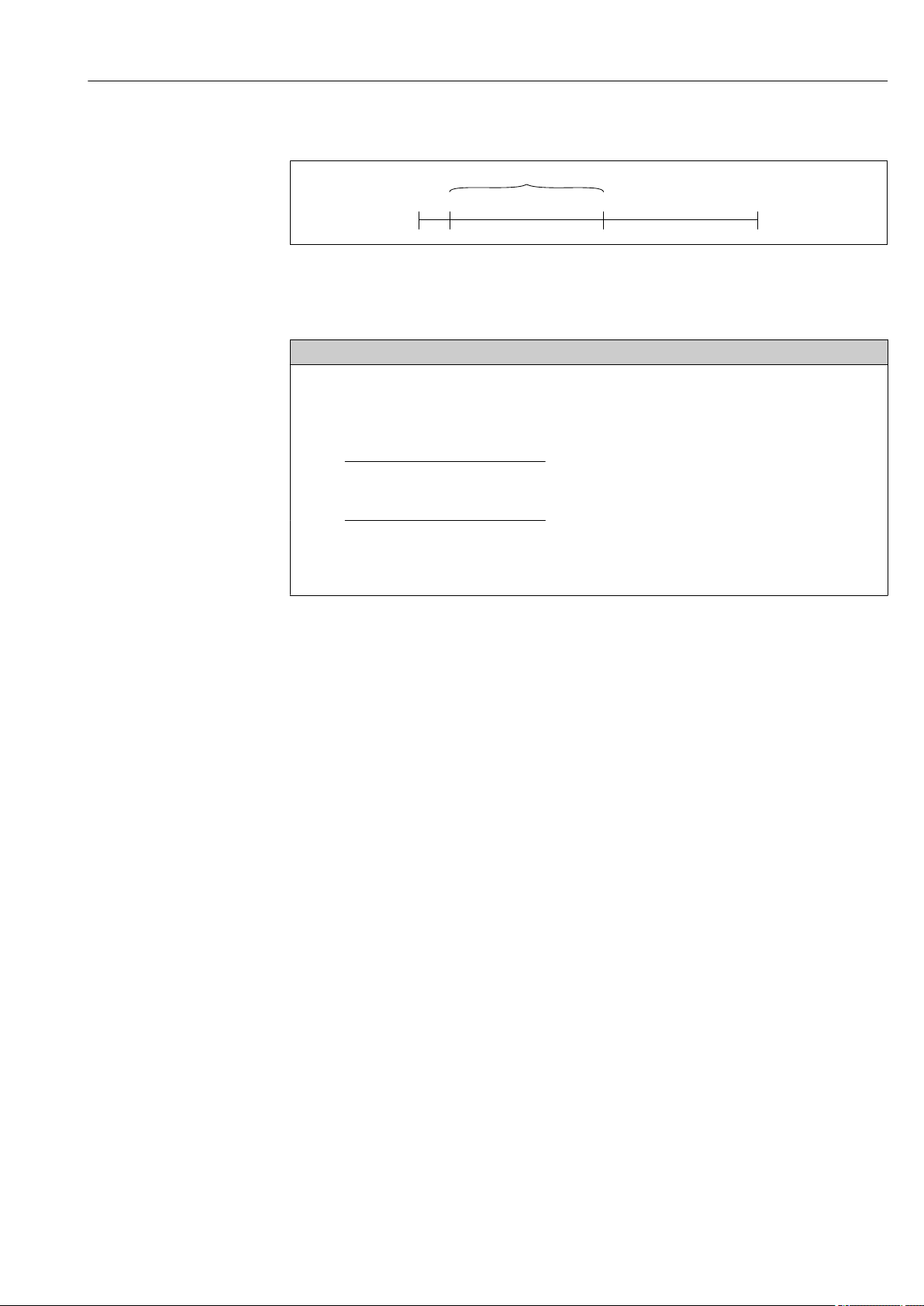
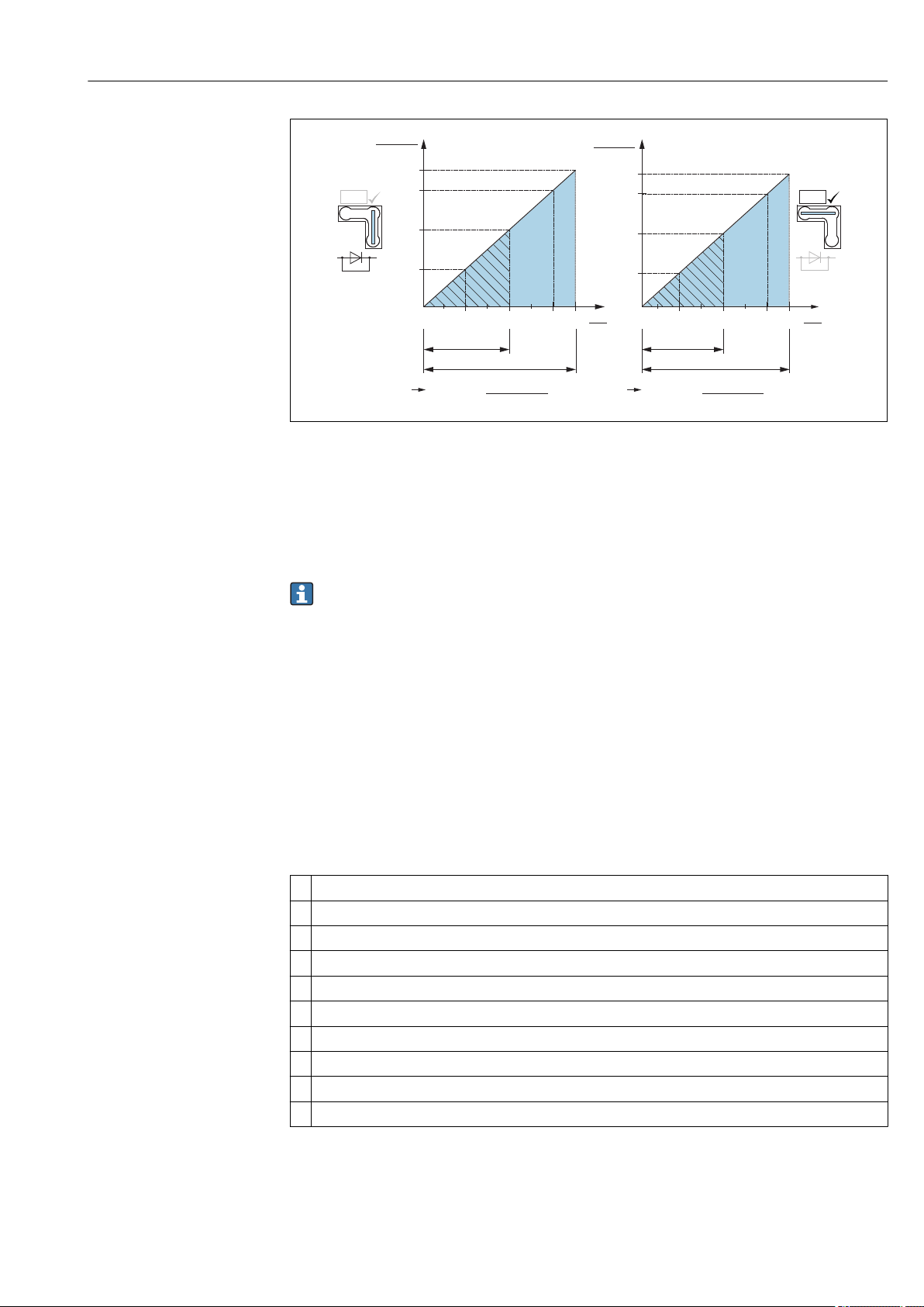
1.4 Terms and abbreviations
A0029505
Position Term/
abbreviation
1 OPL The OPL (over pressure limit = sensor overload limit) for the measuring device
2 MWP The MWP (maximum working pressure) for the sensors depends on the lowest-
3 Maximum sensor
measuring range
4 Calibrated/
p - Pressure
- LRL Lower range limit
- URL Upper range limit
- LRV Lower range value
- URV Upper range value
- TD (Turn down) Turn down
adjusted span
Explanation
depends on the lowest-rated element, with regard to pressure, of the selected
components, i.e. the process connection has to be taken into consideration in
addition to the measuring cell. Also observe pressure-temperature dependency.
For the relevant standards and additional notes, see the "Pressure specifications"
section → 130.
The OPL may only be applied for a limited period of time.
rated element, with regard to pressure, of the selected components, i.e. the
process connection has to be taken into consideration in addition to the
measuring cell. Also observe pressure-temperature dependency. For the
relevant standards and additional notes, see the "Pressure specifications" section
→ 130.
The MWP may be applied at the device for an unlimited period.
The MWP can also be found on the nameplate.
Span between LRL and URL
This sensor measuring range is equivalent to the maximum calibratable/
adjustable span.
Span between LRV and URV
Factory setting: 0 to URL
Other calibrated spans can be ordered as customized spans.
Example - see the following section.
8 Endress+Hauser
Page 9
Deltabar FMD71, FMD72 Document information
LRV
URLURV
LRL
1 = 2
3
1.5 Turn down calculation
A0029545
1 Calibrated/adjusted span
2 Zero point-based span
3 URL sensor
Example
• Sensor:10 bar (150 psi)
• Upper range value (URL) = 10 bar (150 psi)
Turn down (TD):
• Calibrated/adjusted span: 0 to 5 bar (0 to 75 psi)
• Lower range value (LRV) = 0 bar (0 psi)
• Upper range value (URV) = 5 bar (75 psi)
TD =
|URV - LRV|
TD =
|5 bar (75 psi) - 0 bar (0 psi)|
In this example, the TD is 2:1.
This span is based on the zero point.
URL
10 bar (150 psi)
= 2
1.6 Registered trademarks
1.6.1 HART®
Registered trademark of the FieldComm Group, Austin, USA
Endress+Hauser 9
Page 10

Basic safety instructions Deltabar FMD71, FMD72
2 Basic safety instructions
2.1 Requirements concerning the staff
The personnel for installation, commissioning, diagnostics and maintenance must fulfill
the following requirements:
Trained, qualified specialists: must have a relevant qualification for this specific
‣
function and task
Are authorized by the plant owner/operator
‣
Are familiar with federal/national regulations
‣
Before beginning work, the specialist staff must have read and understood the
‣
instructions in the Operating Instructions and supplementary documentation as well as
in the certificates (depending on the application)
Following instructions and basic conditions
‣
The operating personnel must fulfill the following requirements:
Being instructed and authorized according to the requirements of the task by the
‣
facility's owner-operator
Following the instructions in these Operating Instructions
‣
2.2 Designated use
2.2.1 Application and media
The Deltabar FMD72 is a differential pressure transmitter for measuring differential
pressure and level in pressurized tanks. The device has two sensor modules, which
measure the operating pressure (High Pressure HP and Low Pressure LP). The differential
pressure/hydrostatic level is calculated in the transmitter unit. The sensor signal is
transmitted digitally. In addition, sensor temperatures and the individual process pressures
present at the respective sensor modules can be individually evaluated and transmitted. If
the limit values specified in the "Technical Data" and the conditions listed in the
instructions and additional documentation are observed, the measuring device may be
used for the following measurements (process variables):
Measured process variables
• Pressure HP and Pressure LP
• Sensor temperature HP and sensor temperature LP
• Transmitter temperature
Calculated process variables
• Differential pressure
• Level (level, volume or mass)
2.2.2 Incorrect use
The manufacturer is not liable for damage caused by improper or non-designated use.
Verification for borderline cases:
For special fluids and fluids for cleaning, Endress+Hauser is glad to provide assistance
‣
in verifying the corrosion resistance of fluid-wetted materials, but does not accept any
warranty or liability.
2.2.3 Residual risks
Due to heat transfer from the process as well as power loss in the electronics, the
temperature of the electronics housing and the assemblies contained therein (e.g. display
10 Endress+Hauser
Page 11

Deltabar FMD71, FMD72 Basic safety instructions
module, main electronics module and I/O electronics module) may rise up to 80 °C
(176 °F). When in operation, the sensor can reach a temperature close to the medium
temperature.
Danger of burns from contact with surfaces!
For elevated fluid temperature, ensure protection against contact to prevent burns.
‣
2.3 Workplace safety
For work on and with the device:
Wear the required personal protective equipment according to federal/national
‣
regulations.
Switch off the supply voltage before connecting the device.
‣
2.4 Operational safety
Risk of injury!
Operate the device in proper technical condition and fail-safe condition only.
‣
The operator is responsible for interference-free operation of the device.
‣
Modifications to the device
Unauthorized modifications to the device are not permitted and can lead to unforeseeable
dangers.
If, despite this, modifications are required, consult with Endress+Hauser.
‣
Repairs
To ensure continued operational safety and reliability,
Carry out repairs on the device only if they are expressly permitted.
‣
Observe federal/national regulations pertaining to repair of an electrical device.
‣
Use original spare parts and accessories from Endress+Hauser only.
‣
Hazardous area
To eliminate danger to persons or the facility when the device is used in the approvalrelated area (e.g. explosion protection, pressure vessel safety):
Check the nameplate to verify if the device ordered can be put to its intended use in the
‣
approval-related area.
Observe the specifications in the separate supplementary documentation that is an
‣
integral part of these Instructions.
2.5 Product safety
This measuring device is designed in accordance with good engineering practice to meet
state-of-the-art safety requirements, has been tested, and left the factory in a condition in
which it is safe to operate.
It meets general safety standards and legal requirements. It also complies with the EC
directives listed in the device-specific EC Declaration of Conformity. Endress+Hauser
confirms this by affixing the CE mark to the device.
Endress+Hauser 11
Page 12

Product description Deltabar FMD71, FMD72
LP 1
HP
p1
p2
P = p2
LP
P = p1 + p2
HP
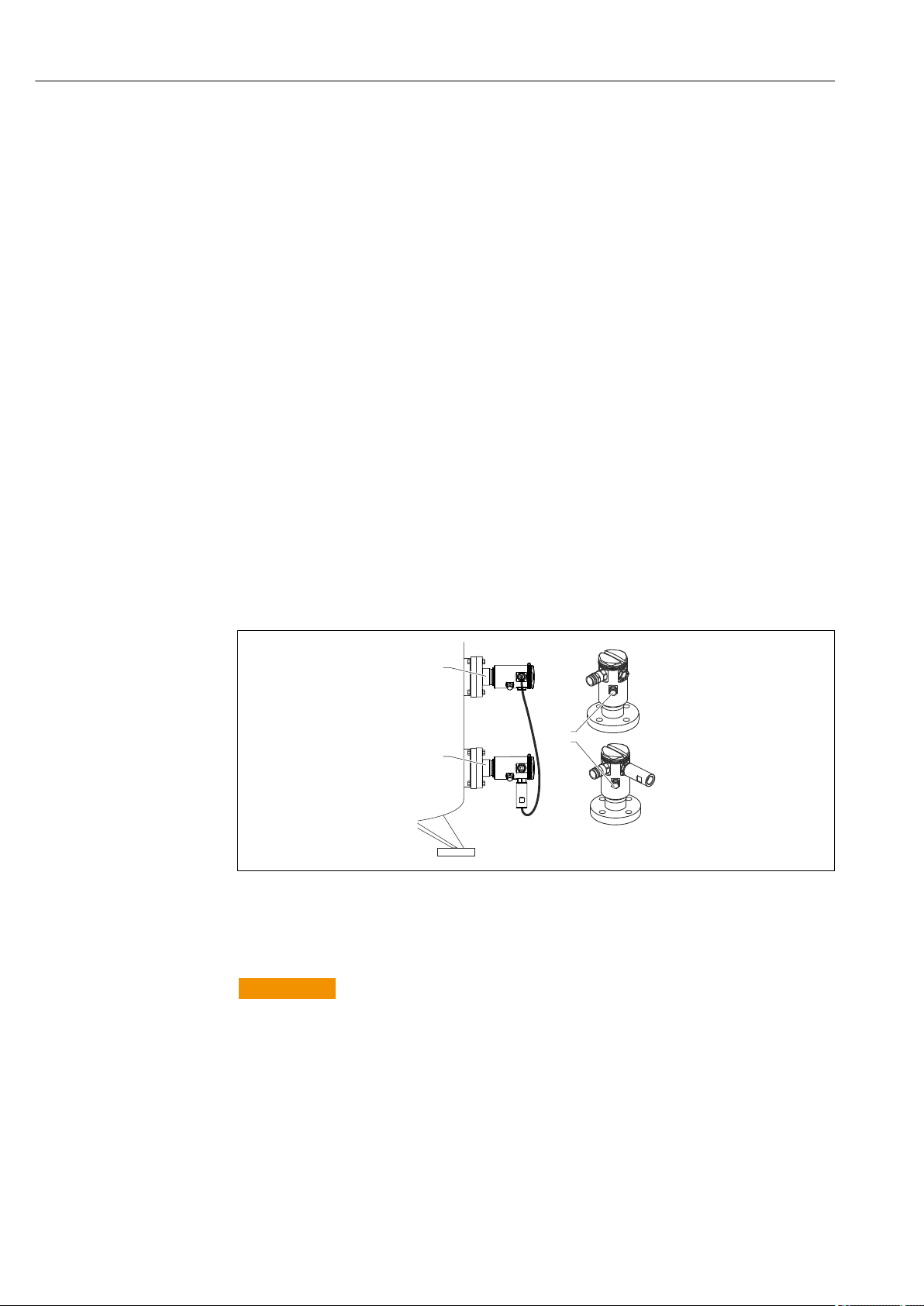
3 Product description
3.1 Product design
Level measurement (level, volume and mass) with Deltabar:
A0016449
LP Sensor module LP (low pressure)
HP Sensor module HP (high pressure)
p2 Head pressure
p1 Hydrostatic pressure
1 Transmitter
The FMD71/FMD72 is best suited to level measurement in vessels with pressure overlay
or in vacuum vessels and tanks, high distillation columns and other vessels with changing
ambient temperatures.
The sensor module HP is mounted on the lower measuring connection and the sensor
module LP is mounted above the maximum level. The transmitter can be mounted on
pipes or walls with the mounting bracket.
The sensor signal is transmitted digitally. In addition, sensor temperatures and the
individual process pressures present at the respective sensor modules can be individually
evaluated and transmitted.
NOTICE
Incorrect sizing/order of sensor modules
In a closed system, please note that the sensor module is affected by the superimposed
‣
head pressure (p2) in addition to the hydrostatic pressure (p1). This must be taken into
account when sizing the sensor module on the high-pressure side (HP).
12 Endress+Hauser
Page 13
Deltabar FMD71, FMD72 Product description
3.2 Function
3.2.1 Differential pressure generation
The measurement chain for the calculation of the differential pressure can be represented
by the following diagram:
LP →
HP →
Sensor
pressure LP
↑ ↑
Sensor
calibration LP
Sensor
calibration HP
↓ ↓
Sensor
pressure HP
Sensor trim LP
→
Sensor trim
→
HP
All the process values represented on the diagram are updated in a measurement cycle.
The sensor module allocation is determined by the configuration when setting up the
device. The connection to the transmitter defines the corresponding sensor module as the
master. After commissioning, the second sensor module is detected as the slave. This
configuration can be modified as desired. However, a modification must take place with
the unit disconnected from the power supply.
The sensor modules have a designation independent of the master/slave configuration.
This indicates where the sensor module is typically installed:
• Sensor module LP
LP = Low pressure; top
• Sensor module HP
HP = High pressure; bottom
For identical sensor module ranges, this assignment can likewise be changed, but this then
has to be configured in the menu.
If you change both sensor modules or the electronics, this allocation must likewise be
carried out. See the "Transm. connect. (286)" parameter .
Measured
pressure LP
Pressure
→
simulation LP
Differential
pressure +
pressure
inversion
Pressure
→
simulation HP
Measured
pressure HP
Corrected
pressure
↓
→
↑
↑ ↑ ↑
Position
adjustment
(calib. offset)
→
Differential
pressure
simulation
Pressure after
damping
→ Damping → P
Measured
differential
pressure
Endress+Hauser 13
Page 14
Incoming acceptance and product identification Deltabar FMD71, FMD72
DELIVERY NOTE
1 = 2
DELIVERYNOTE
Span
Ser. no.:
Order code:
P
U:
Deltabar
Ext. order code:
Order Code:
Ser.-No.:
MWP
Span
U=
Mat.
-
Dat.:
0044
Mat.:
P
Ser. no.:
MWP
Sensor module Deltabar
4 Incoming acceptance and product
identification
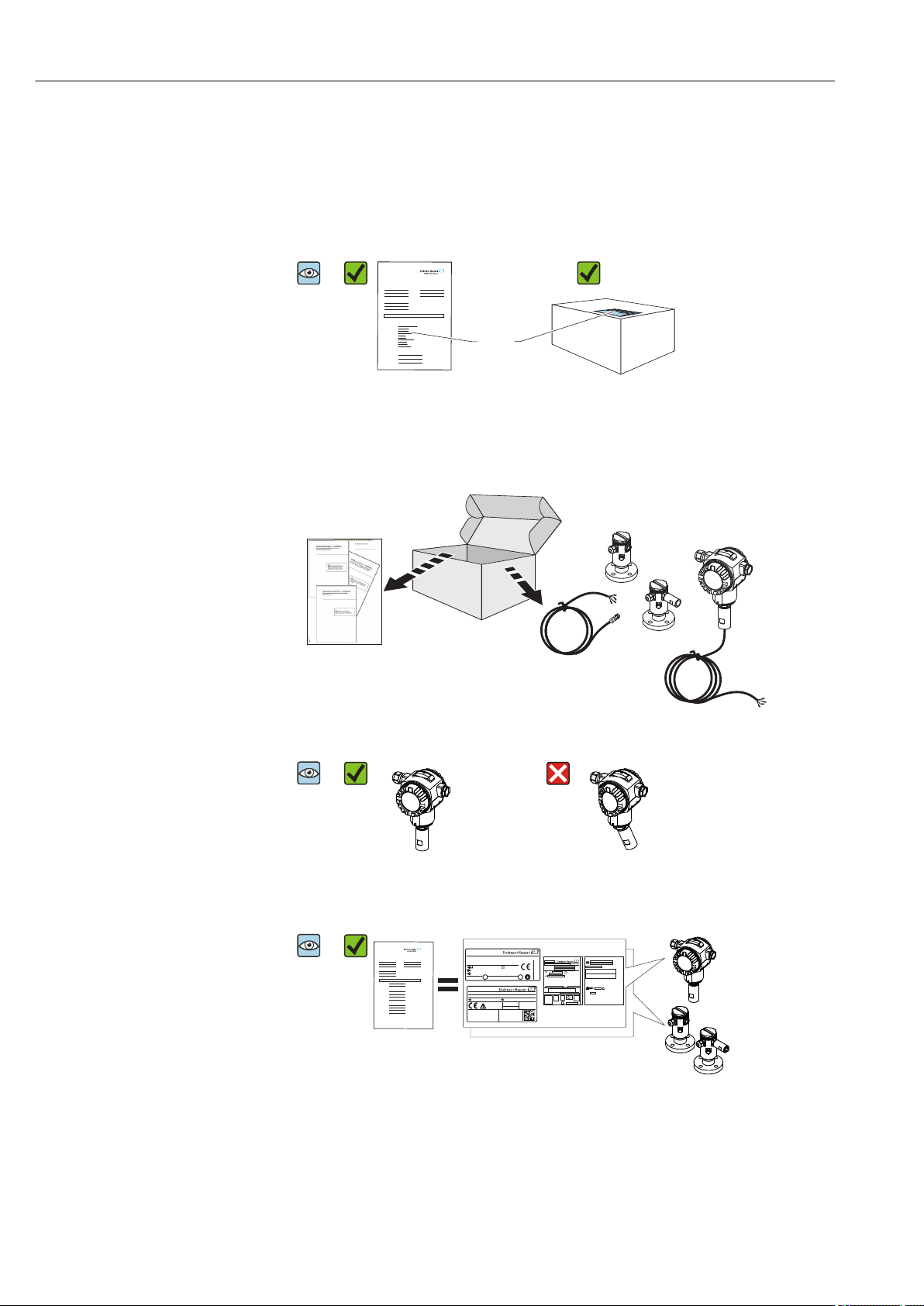
4.1 Incoming acceptance
A0028673
A0016870
Is the order code on the delivery note (1) identical to the order code on
the product sticker (2)?
A0016052
A0028673
A0016053
Are the goods undamaged?
A0028673
A0016054
Do the data on the nameplate correspond to the order specifications and
the delivery note?
14 Endress+Hauser
Page 15
Deltabar FMD71, FMD72 Incoming acceptance and product identification
Ser. no.:
Order code:
Ext. order code:
2
5
6
3
4
1
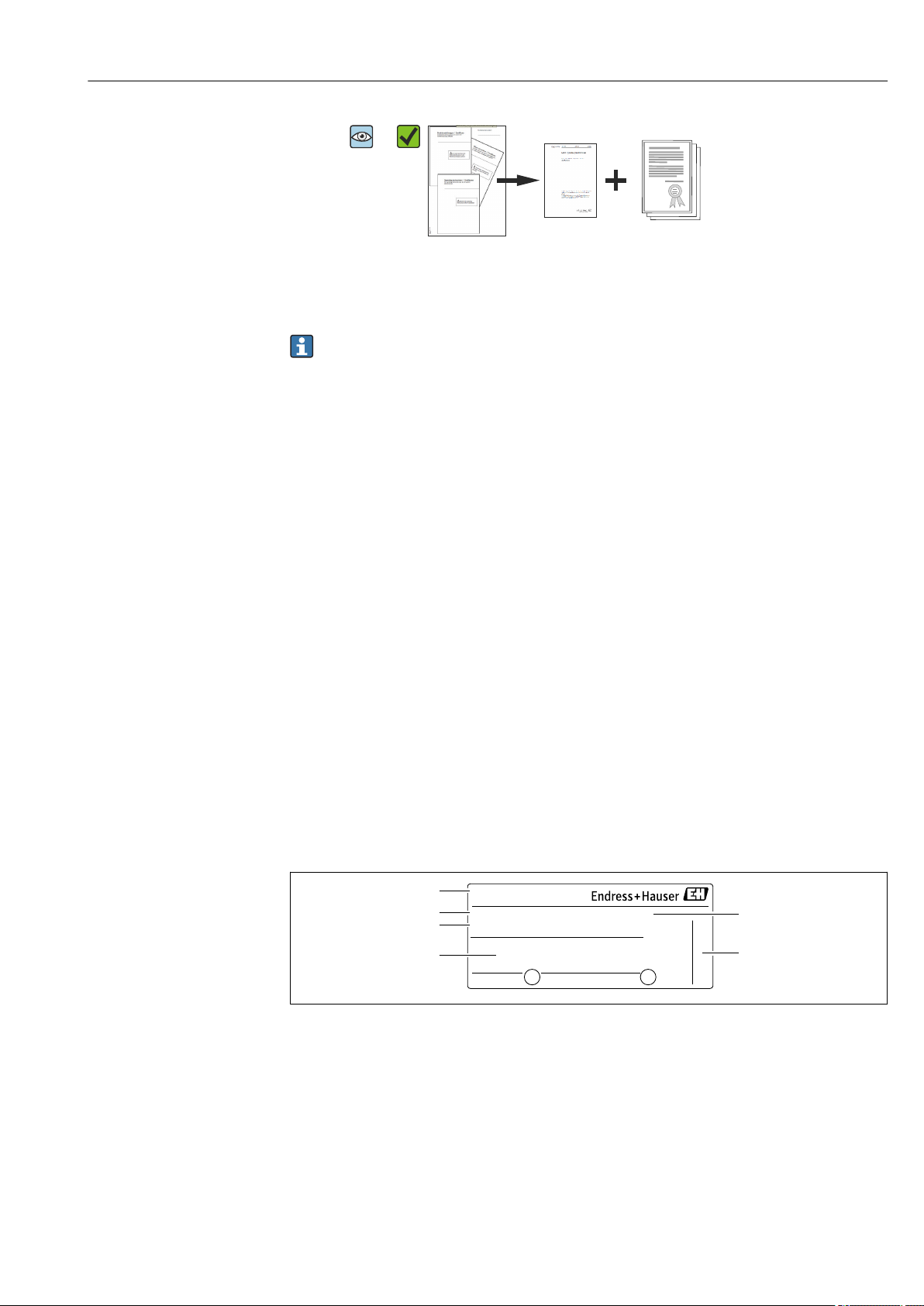
A0028673
A0022106
Is the documentation provided?
If required (see nameplate): Are the safety instructions (XA) present?
If one of these conditions is not fulfilled, please contact your
Endress+Hauser sales office.
4.2 Product identification
The following options are available for identification of the measuring device:
• Nameplate specifications
• Order code with breakdown of the device features on the delivery note
• Enter serial numbers from nameplates in W@M Device Viewer
(www.endress.com/deviceviewer): All information about the measuring device is
displayed.
For an overview of the technical documentation provided, enter the serial number from
the nameplates in W@M Device Viewer (www.endress.com/deviceviewer)
4.2.1 Manufacturer address
Endress+Hauser GmbH+Co. KG
Hauptstraße 1
79689 Maulburg, Germany
Address of the manufacturing plant: See nameplate.
4.3 Nameplates
4.3.1 Nameplates of the T14 transmitter housing
1 Device name
2 Order code (for re-orders)
3 Extended order code (complete)
4 Technical data
5 Serial number (for identification)
6 Manufacturer address
A0016056
Endress+Hauser 15
Page 16
Incoming acceptance and product identification Deltabar FMD71, FMD72
2
1
1
2
7
3
4
5
6
1
Ser. no.:
Order code:
Ext. ord. cd.:
Additional nameplate for devices with Ex approval
A0021222
1 Approval-specific information
2 Document number of Safety Instructions or drawing number
Additional nameplate for devices with PVDF process connection
A0022683
1 application limits
4.3.2 Nameplates of the T17 transmitter housing
1 Device name
2 Manufacturer address
3 Order code (for re-orders)
4 Extended order code (complete)
5 Serial number (for identification)
6 Technical data
7 Approval-related information and document number of Safety Instructions or drawing number
A0021552
16 Endress+Hauser
Page 17

Deltabar FMD71, FMD72 Incoming acceptance and product identification
0044
Mat.:
P
Ser. no.:
MWP
Sensor module Deltabar
2
1
4.3.3 Nameplate of the sensor housing
A0021224
1 Sensor serial number
2 Identification of sensor type (HP/LP)
4.4 Storage and transport
4.4.1 Storage conditions
Use original packaging.
Store the measuring device in clean and dry conditions and protect from damage caused by
shocks (EN 837-2).
Storage temperature range
–40 to +80 °C (–40 to +176 °F)
4.4.2 Transporting the product to the measuring point
WARNING
L
Incorrect transport!
Housing and diaphragm may become damaged, and there is a risk of injury!
Transport the measuring device to the measuring point in its original packaging or by
‣
the process connection.
Follow the safety instructions and transport conditions for devices weighing more than
‣
18 kg (39.6 lbs).
A0016058
Endress+Hauser 17
Page 18

Installation Deltabar FMD71, FMD72
5 Installation
• Moisture must not penetrate the housing when mounting the device, establishing the
electrical connection and during operation.
• When measuring in media containing solids, such as dirty liquids, installing separators
and drain valves is useful for capturing and removing sediment.
• Do not clean or touch process isolating diaphragms with hard and/or pointed objects.
• Do not remove process isolating diaphragm protection until shortly before installation.
• Always firmly tighten the housing cover and the cable entries.
• Point the cable and connector downwards where possible to prevent moisture from
entering (e.g. rain or condensation water).
5.1 Mounting dimensions
For dimensions, see the "Mechanical construction" section in the Technical Information.
5.2 Mounting location
The FMD71/FMD72 is best suited to level measurement in vessels with pressure overlay
or in vacuum vessels and tanks, high distillation columns and other vessels with changing
ambient temperatures.
The sensor module HP is mounted on the lower measuring connection and the sensor
module LP is mounted above the maximum level. The transmitter can be mounted on
pipes or walls with the mounting bracket.
5.3 Orientation
• Transmitter: Any orientation.
• Sensor modules: The orientation can cause a zero point shift .
This position-dependent zero point shift can be corrected directly at the device via the
operating key, and also in hazardous areas in the case of devices with external operation
(position adjustment).
5.4 General installation instructions
Mounting the sensor modules and transmitter is very easy
• The housings of the sensor modules can be rotated up to 360°.
• The transmitter is freely rotatable in the mounting bracket.
The sensor modules and transmitter can be easily aligned when mounted.
Your benefits
• Easy mounting due to optimum alignment of housing
• Easily accessible device operation
• Optimum readability of the onsite display (optional)
• Easy pipe installation due to optional alignment of the modules.
18 Endress+Hauser
Page 19

Deltabar FMD71, FMD72 Installation
2 mm
3 mm
A
B
1 2
A0017506
5.5 Thermal insulation - FMD71 high-temperature version
The FMD71 high-temperature version may only be insulated up to a certain height. The
maximum permitted insulation height is indicated on the devices and applies to an
insulation material with a heat conductivity ≤ 0.04 W/(m x K) and to the maximum
permitted ambient and process temperature. The insulation height is not indicated on
hygienic connections.
• Ambient temperature (TA): ≤ 70 °C (158 °F)
• Process temperature (TP): ≤ 150 °C (302 °F)
The data were determined under the most critical application "quiescent air".
A Ambient temperature
B Process temperature
1 Insulation height
2 Insulation material
A0021075
Endress+Hauser 19
Page 20
Installation Deltabar FMD71, FMD72
2
3
1
5.6 Installing the sensor modules
5.6.1 General installation instructions
• The nameplate on the sensor module specifies where the sensor module is typically
installed:
HP (bottom)
LP (top)
For further information, see the "Function" section → 13.
• Due to the orientation of the sensor modules, there may be a shift in the zero point, i.e.
when the vessel is empty or partially full, the measured value does not display zero.
You can correct this zero point shift: see the "Commissioning without an operating menu"
→ 42or the "Position adjustment"→ 47 section.
• Always install the sensor module HP below the lowest measuring point.
• Always install the sensor module LP above the highest measuring point.
• Do not mount the sensor modules in the filling curtain or at a point in the tank which
could be affected by pressure pulses from an agitator.
• Do not mount the sensor modules in the suction area of a pump.
• The adjustment and functional test can be carried out more easily if you mount the
sensor modules downstream of a shutoff device.
• If a heated sensor module is cooled during the cleaning process (e.g. by cold water), a
vacuum develops for a short time, whereby moisture can penetrate the sensor through
the pressure compensation (3). If this is the case, mount the sensor with the pressure
compensation (3) pointing downwards.
• Keep the pressure compensation and GORE-TEX® filter (3) free from contamination.
• Do not clean or touch process isolating diaphragms with hard or pointed objects.
5.7 Mounting sensor modules with PVDF installation
coupling
WARNING
L
Risk of damage to process connection!
Risk of injury!
Sensor modules with PVDF process connections with threaded connection must be
‣
installed with the mounting bracket provided!
20 Endress+Hauser
A0017512
Page 21
Deltabar FMD71, FMD72 Installation
WARNING
L
Material fatigue from pressure and temperature!
Risk of injury due to bursting of parts! The thread can become lose if exposed to high
pressure and temperature loads.
The integrity of the thread must be checked regularly and the thread may need to be
‣
retightened with the maximum tightening torque of 7 Nm (5.16 lbf ft). Teflon tape is
recommended for sealing the ½" NPT thread.
The mounting bracket can be installed on pipes with a diameter of 1¼" to 2" or on walls.
In the case of pipe mounting, the nuts on the bracket must be tightened uniformly with a
torque of at least 5 Nm (3.69 lbf ft).
A0017514
• The mounting bracket is included in the delivery.
• Ordering information:
Product Configurator order code for "Enclosed accessories", option "PA" or
as a separate accessory (part no.: 71102216).
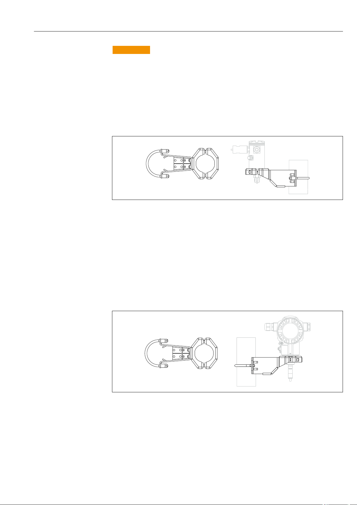
5.8 Installing the transmitter
The transmitter is installed with the mounting bracket supplied. The mounting bracket can
be installed on pipes with a diameter of 1¼" to 2" or on walls.
In the case of pipe mounting, the nuts on the bracket must be tightened uniformly with a
torque of at least 5 Nm (3.69 lbf ft).
A0021145
The mounting bracket is included in the delivery.
Endress+Hauser 21
Page 22

Installation Deltabar FMD71, FMD72
1.
4.
3.
2.
5.8.1 Turning the display module
A0017524
WARNING
L
Supply voltage switched off?
Risk of electric shock and/or explosion!
Switch off the supply voltage before connecting the device.
‣
1. If present (i.e. in devices with Ex d and Ex na approval), release the securing clamp of
the electronics compartment cover with an Allen key.
2. Unscrew the electronics compartment cover from the transmitter housing.
3. Pull out the display module with a gentle rotational movement.
4. Rotate the display module into the desired position: max. 4 × 90° in each direction.
5. Fit the display module on the electronics compartment in the desired position until it
clicks into place.
6. Screw the electronics compartment cover back onto the transmitter housing.
7. If present (i.e. in devices with Ex d and Ex na approval), tighten the securing clamp
with an Allen key (1 Nm (0.225 lbf)).
5.9 Closing the housing cover
NOTICE
The housing cover can no longer be closed.
Damaged thread!
When closing the housing cover, please ensure that the thread of the cover and
‣
housing are free from dirt, e.g. sand. If you feel any resistance when closing the cover,
check the thread on both again to ensure that they are free from dirt.
5.9.1 Closing the covers on the hygienic stainless steel housing (T17)
The covers for the terminal compartment and electronics compartment are hooked into
the housing and closed with a screw in each case. These screws must be tightened fingertight (2 Nm (1.48 lbf ft)) to the stop to ensure that the covers are securely seated and
22 Endress+Hauser
leak-tight.
Page 23
Deltabar FMD71, FMD72 Installation
1 2
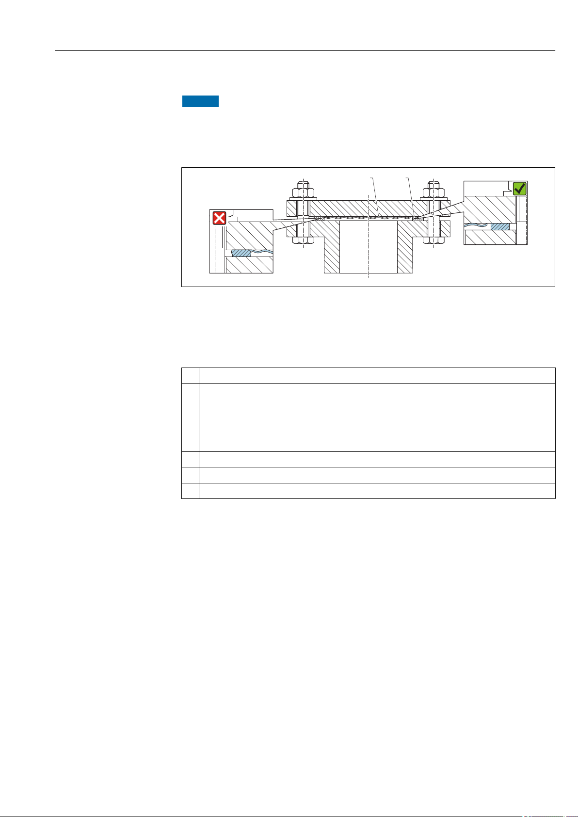
5.10 Seal for flange mounting
NOTICE
Distorted measurement results.
The seal is not allowed to press against the process isolating diaphragm as this could affect
the measurement result.
Ensure that the seal is not touching the process isolating diaphragm.
‣
A0017743
1 Process isolating diaphragm
2 Seal
5.11 Post-installation check
Is the device undamaged (visual inspection)?
Does the device comply with the measuring point specifications?
For example:
• Process temperature
• Process pressure
• Ambient temperature
• Measuring range
Are the measuring point identification and labeling correct (visual inspection)?
Is the device adequately protected against precipitation and direct sunlight?
Are the securing screw and securing clamp tightened securely?
Endress+Hauser 23
Page 24
Electrical connection Deltabar FMD71, FMD72
6
7
5
5
6
2 3 4
3
4
1
21
6
NPT ½"
M20
8
6 Electrical connection
WARNING
L
If the operating voltage is > 35 VDC: Dangerous contact voltage at terminals.
Risk of electric shock!
In a wet environment, do not open the cover if voltage is present.
‣
The sensor modules have a designation independent of the master/slave
configuration. This indicates where the sensor module is typically installed:
• Sensor module LP
LP = Low pressure; top
• Sensor module HP
HP = High pressure; bottom
For further information, see the "Function" section → 13.
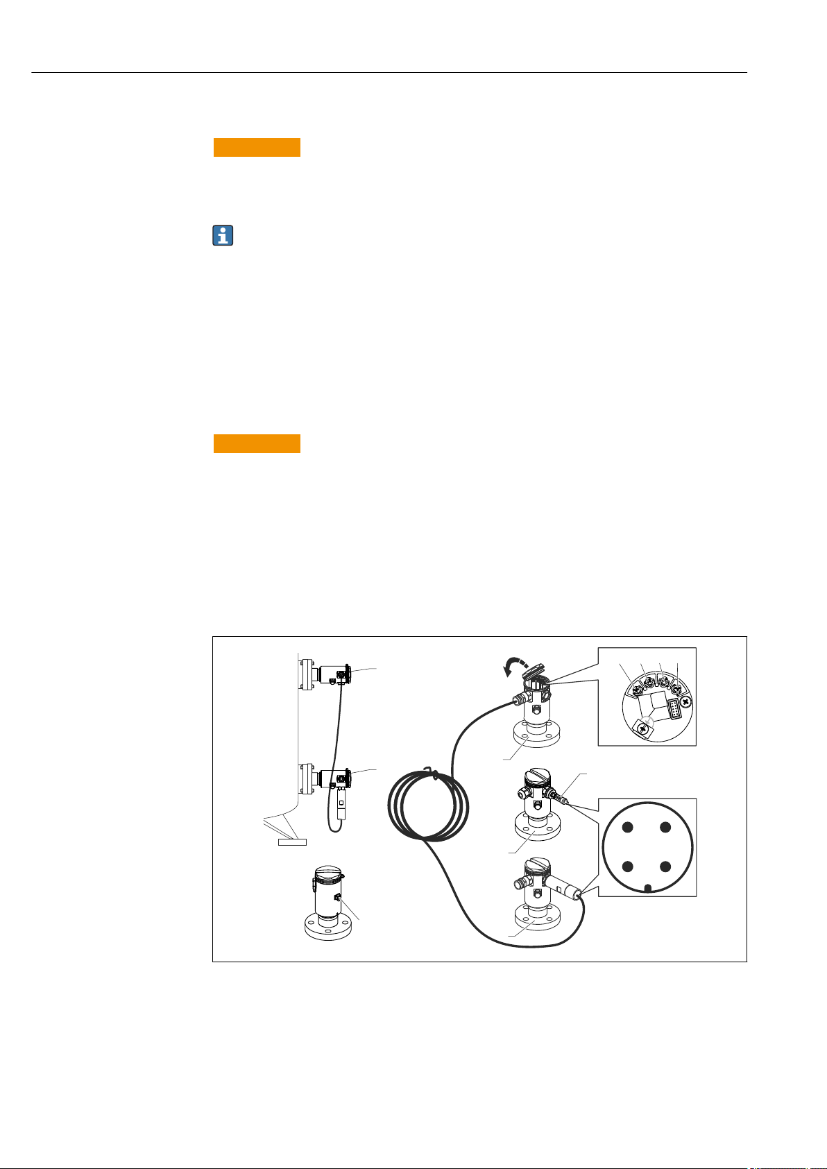
6.1 Connecting the sensor module LP to the sensor module HP
WARNING
L
Supply voltage might be connected!
Risk of electric shock and/or explosion!
Switch off the supply voltage before connecting the device.
‣
• Screw on the housing cover of the terminal compartment of the sensor module LP.
• Guide the cable of the sensor module HP through the cable gland of the sensor module
LP. Use the shielded 4-wire cable that is provided. The wire ends are color-coded to
match the corresponding terminal.
• Connect device in accordance with the following diagrams.
• Screw down housing cover.
A0017528
24 Endress+Hauser
1 BK (black)
2 BU (blue)
3 WH (white)
4 BN (brown)
5 Sensor module LP
6 Sensor module HP
7 Ground terminal
8 Torque 0.4 Nm
Page 25
Deltabar FMD71, FMD72 Electrical connection
6
5
5
7
2 3 4
3
4
1
21
6
5
NPT ½"
M20
8
8
6.1.1 Screening with cable shield
Screening with cable shield is described in the associated documentation SD00354P. The
documentation is provided with the connecting cables.
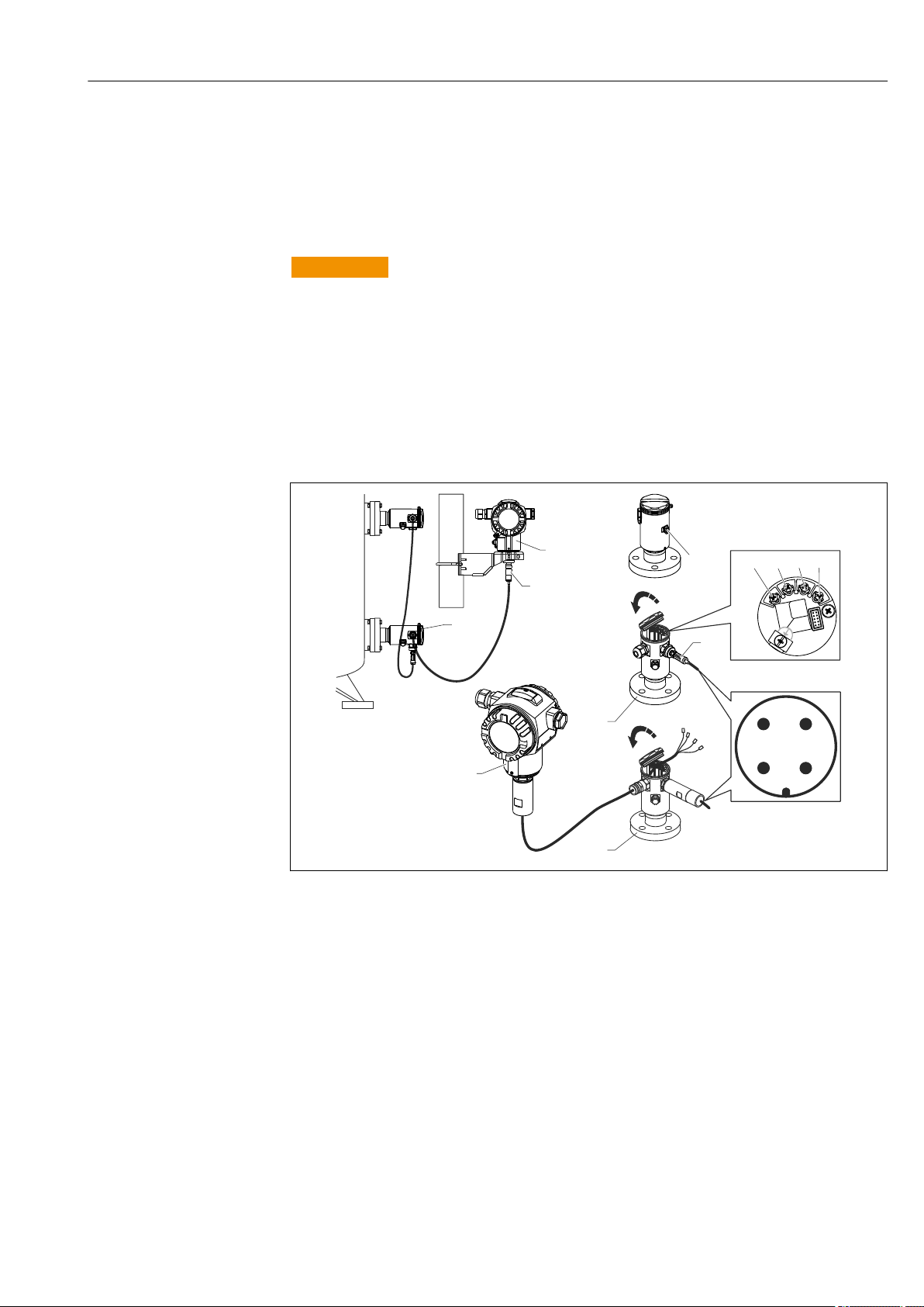
6.2 Connecting the sensor module HP to the transmitter
WARNING
L
Supply voltage might be connected!
Risk of electric shock and/or explosion!
Switch off the supply voltage before connecting the device.
‣
• Screw on the housing cover of the terminal compartment of the sensor module HP.
• Guide the cable of the transmitter through the cable gland of the sensor module HP. Use
the shielded 4-wire cable that is provided. The wire ends are color-coded to match the
corresponding terminal.
• Connect device in accordance with the following diagram.
• Screw down housing cover.
A0017529
1 BK (black)
2 BU (blue)
3 WH (white)
4 BN (brown)
5 Sensor module HP
6 Transmitter
7 Ground terminal
8 Torque 0.4 Nm
6.2.1 Screening with cable shield
Endress+Hauser 25
Screening with cable shield is described in the associated documentation SD00354P. The
documentation is provided with the connecting cables.
Page 26
Electrical connection Deltabar FMD71, FMD72
4... 20mA
Test
Test
Test
4... 20mA Test
1
8
6
7
2
3
4
5
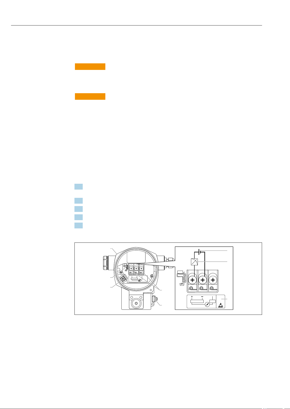
6.3 Connecting the measuring unit
6.3.1 Terminal assignment
WARNING
L
Supply voltage might be connected!
Risk of electric shock and/or explosion!
Switch off the supply voltage before connecting the device.
‣
WARNING
L
Electrical safety is compromised by an incorrect connection!
In accordance with IEC/EN61010 a separate circuit breaker must be provided for the
‣
device .
When using the measuring device in hazardous areas, installation must comply with
‣
the corresponding national standards and regulations and the Safety Instructions or
Installation or Control Drawings.
All explosion protection data are given in separate documentation which is available
‣
upon request. The Ex documentation is supplied as standard with all devices approved
for use in explosion hazardous areas.
Devices with integrated overvoltage protection must be grounded.
‣
Protective circuits against reverse polarity, HF influences and overvoltage peaks are
‣
integrated.
Connect the device in the following order:
1. Check whether the supply voltage matches the supply voltage indicated on the
nameplate.
2. Remove the housing cover.
3. Guide cable through the gland.
4. Connect device in accordance with the following diagram.
5. Screw down housing cover.
Switch on supply voltage.
A0019989
1 Housing
2 Supply voltage
3 4 to 20 mA
4 Devices with integrated overvoltage protection are labeled "OVP" (overvoltage protection) here.
5 External ground terminal
6 4 to 20 mA test signal between positive and test terminal
7 Internal ground terminal, minimum supply voltage = 12 V DC, jumper is set as illustrated in the diagram.
8 Jumper for 4 to 20 mA test signal,
26 Endress+Hauser
Page 27
Deltabar FMD71, FMD72 Electrical connection
Test
Test
6.3.2 Supply voltage
WARNING
L
Supply voltage might be connected!
Risk of electric shock and/or explosion!
When using the measuring device in hazardous areas, installation must comply with
‣
the corresponding national standards and regulations as well as the Safety Instructions.
All explosion protection data are given in separate documentation which is available
‣
upon request. The Ex documentation is supplied as standard with all devices approved
for use in explosion hazardous areas.
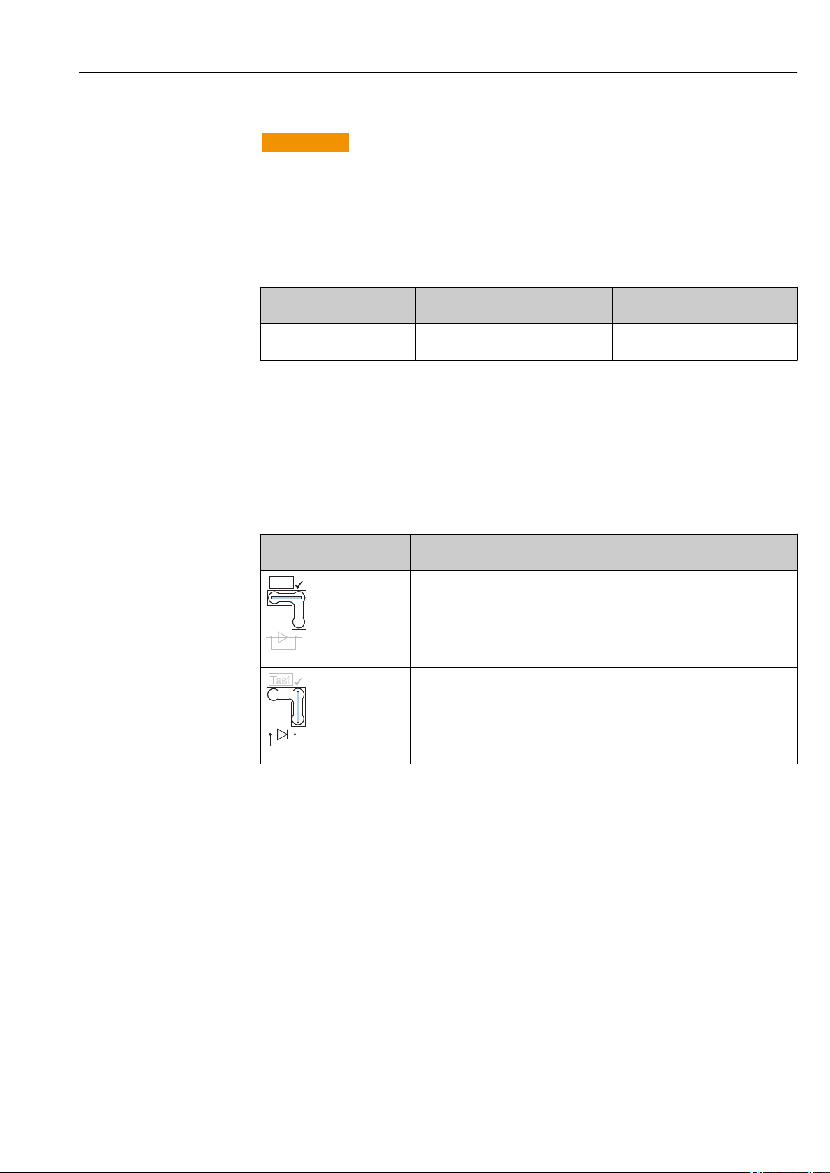
Electronic version Jumper for 4 to 20 mA test signal in
"Test" position (delivery status)
4 to 20 mA HART, version for
non-hazardous areas
13 to 45 V DC 12 to 45 V DC
Jumper for 4 to 20 mA test signal
in "Non-test" position
Measuring a 4 to 20 mA test signal
A 4 to 20 mA test signal may be measured via the positive and test terminal without
interrupting the measurement. The minimum supply voltage of the device can be reduced
by simply changing the position of the jumper. As a result, operation is also possible with a
lower supply voltage. To keep the measured error below 0.1 %, the current measuring
device should exhibit an internal resistance of <0.7Ω. Observe the position of the jumper in
accordance with the following table.
Jumper position for test
signal
Description
• Measurement of 4 to 20 mA test signal via the positive and test terminal:
possible. (Thus, the output current can be measured without interruption via
the diode.)
• Delivery status
• Minimum supply voltage: 13 V DC
A0019992
• Measurement of 4 to 20 mA test signal via positive and test terminal: not
possible.
• Minimum supply voltage: 12 V DC
A0019993
6.4 Connection conditions
6.4.1 Cable specification
Preferably use twisted, screened two-wire cable.
6.4.2 Cable specification for transmitter connection
• Endress+Hauser recommends using twisted, shielded two-wire cables.
• Terminals for core cross-sections 0.5 to 2.5 mm2 (20 to 14 AWG)
• The cable outer diameter depends on the cable entry used.
Endress+Hauser 27
Page 28

Electrical connection Deltabar FMD71, FMD72
6.4.3 Cable entries
Explosion protection Cable gland Permitted cable diameter Permitted wire cross-sections
• Standard
• Ex ia
• Ex ic
• Ex tD
• Ex nA
• FM approval
• CSA approval
Plastic M20x1.5 5 to 10 mm (0.2 to 0.39 in) 0.5 to 2.5 mm2 (20 to 14 AWG)
Metal M20 x 1.5 7 to 10.5 mm (0.28 to 0.41 in)
6.4.4 Overvoltage protection
Standard version
The standard version of the pressure instruments does not contain any special elements to
protect against overvoltage ("wire to ground"). Nevertheless the requirements of the
applicable EMC standard EN 61000-4-5 (testing voltage 1kV EMC wire/ground) are met.
Optional overvoltage protection
Devices showing version "NA" in feature 610 "Accessory Mounted" in the order code are
equipped with overvoltage protection.
• Overvoltage protection:
– Nominal functioning DC voltage: 600 V
– Nominal discharge current: 10 kA
• Surge current check î = 20 kA satisfied as per DIN EN 60079-14: 8/20 μs
• Arrester AC current check I = 10 A satisfied
NOTICE
Device could be destroyed!
Devices with integrated overvoltage protection must be grounded.
‣
6.5 Connection data
6.5.1 Maximum load
In order to guarantee sufficient terminal voltage in two-wire devices, a maximum load
resistance R (including line resistance) must not be exceeded depending on the supply
voltage U0 of the supply unit.
In the following load diagrams, observe the position of the jumper and the explosion
protection:
28 Endress+Hauser
Page 29
Deltabar FMD71, FMD72 Electrical connection
U – 12 V
U – 13 V
R
L
max
23 mA
23 mA
£
30
20
12
U
[V]
40 45
1217
1435
783
348
[ ]W
[ ]W
R
L
max
R
L
max
30
20
13
40 45
1174
1391
739
304
Test
Test
£
3
A B
1
3
2
1
2
R
L
max
U
[V]
A0017533
A Jumper for 4 to 20 mA test signal set to "Non-test" position
B Jumper for 4 to 20 mA test signal set to "Test" position
1 Power supply for II 1/2 G Ex ia, FM IS, CSA IS
2 Power supply for devices for the non-hazardous area, 2 G Ex d, 3 G Ex nA, FM XP, FM NI, CSA XP, CSA dust
ignition-proof
3 R
U Supply voltage
maximum load resistance
Lmax
When operating via a handheld terminal or via a PC with an operating program, a
minimum communication resistance of 250 Ω must be taken into account.
6.5.2 Shielding
You achieve optimum shielding against disturbances if the shielding is connected on both
sides (in the cabinet and on the device). If potential equalization currents are expected in
the plant, only ground shielding on one side, preferably at the transmitter.
When using in hazardous areas, you must observe the applicable regulations. Separate Ex
documentation with additional technical data and instructions is included with all Ex
systems as standard.
6.6 Post-connection check
Is the device or cable undamaged (visual inspection)?
Do the cables comply with the requirements?
Do the mounted cables have adequate strain relief?
Are all the cable glands installed, tightened and sealed?
Does the supply voltage match the specifications on the nameplate?
Is the terminal assignment correct ?
If required: Has protective ground connection been established?
If supply voltage is present, is the device ready for operation and do values appear on the display module?
Are all the housing covers installed and tightened?
Is the securing clamp tightened correctly?
Endress+Hauser 29
Page 30

Operation options Deltabar FMD71, FMD72
on
off
damp.
Display
Sensor
HART
R
FIELD COMMUNICATION PROTOCOL
SW /min
t
on
off
1 2
3
4
5
6
SW/min
7 8
7 Operation options
7.1 Operation without operating menu
7.1.1 Position of operating elements
Operating keys on the exterior of the device
With the T14 housing (aluminum or stainless steel), the operating keys are located either
outside of the housing, under the protection cap or inside on the electronic insert. In
addition, devices with an onsite display and a 4 to 20 mA HART electronic insert have
operating keys on the onsite display.
A0016499
The operating keys on the outside of the device make it unnecessary to open the housing.
This guarantees:
• Complete protection against environmental influences such as moisture and
contamination
• Simple operation without any tools
• No wear.
Operating keys and elements located internally on the electronic insert
1 DIP switch for locking/unlocking parameters relevant to the measured value
2 DIP switch for switching damping on/off
3 DIP switch for alarm current SW/Alarm min (3.6 mA)
4...5 Not assigned
6 Green LED to indicate value being accepted
7 Operating keys
8 Slot for optional display
30 Endress+Hauser
A0016500
Page 31

Deltabar FMD71, FMD72 Operation options
Function of the DIP switches
Switch Symbol/
labeling
1
2
damping t
3 SW/Alarm min The alarm current is defined by the setting
Switch position
"off" "on"
The device is unlocked. Parameters relevant
to the measured value can be modified.
A0011978
Damping is switched off. The output signal
follows measured value changes without
any delay.
in the operating menu. ("Setup" → "Extended
setup" → "Current output" → "Output fail
2)
mode")
The device is locked. Parameters
relevant to the measured value cannot
be modified.
Damping is switched on. The output
signal follows measured value changes
with the delay time t.
1)
The alarm current is 3.6 mA (min),
regardless of the setting in the
operating menu.
1) The value for the delay time can be configured via the operating menu ("Setup" → "Damping"). Factory
setting: t = 2 s or as per order specifications.
2) Factory setting: 22 mA
Function of the operating elements
Operating key(s) Meaning
Press for at least 3 seconds Adopt lower range value. A reference
pressure is present at the device.
A0017535
Press for at least 3 seconds Adopt upper range value. A reference
A0017536
Press for at least 3 seconds Position adjustment
For a detailed description, see also
"Pressure measuring mode" section,
→ 42or "Level measuring mode"
→ 43 section.
pressure is present at the device.
For a detailed description, see also
"Pressure measuring mode" section,
→ 42or "Level measuring mode"
→ 43 section.
A0017535
and
A0017536
and
A0017537
Press for at least 6 seconds Reset all parameters. The reset via
operating keys corresponds to the
A0017537
software reset code 7864.
Endress+Hauser 31
Page 32

Operation options Deltabar FMD71, FMD72
7.2 Operation with an operating menu
7.2.1 Operation concept
Operation with an operating menu is based on an operation concept with "user roles" .
User role Meaning
Operator Operators are responsible for the devices during normal "operation". This is usually limited to
reading process values either directly at the device or in a control room. If the work with the
devices extends beyond value read-off tasks, the tasks involve simple, applicationspecific
functions that are used in operation. Should an error occur, these users simply forward the
information on the errors but do not intervene themselves.
Maintenance Service engineers usually work with the devices in the phases following device commissioning.
They are primarily involved in maintenance and troubleshooting activities for which simple
settings have to be made at the device. Technicians work with the devices over the entire life
cycle of the product. Thus, commissioning and advanced settings and configurations are some of
the tasks they have to carry out.
Expert Experts work with the devices over the entire life cycle of the device, but, at times, have high
device requirements. Individual parameters/functions from the overall functionality of the
devices are required for this purpose time and again. In addition to technical, process-oriented
tasks, experts can also perform administrative tasks (e.g. user administration). "Experts" can
access the entire parameter set.
7.3 Structure of the operating menu
User role Submenu Meaning/use
Operator Language Only consists of the "Language" parameter (000) where the operating language for
the device is specified. The language can always be changed even if the device is
locked.
Operator Display/
operat.
Maintenance Setup Contains all the parameters that are needed to commission measuring operations.
Contains parameters that are needed to configure the measured value display
(selecting the values displayed, display format, display contrast, etc.). With this
submenu, users can change the measured value display without affecting the actual
measurement.
This submenu has the following structure:
• Standard setup parameters
A wide range of parameters, which can be used to configure a typical application,
is available at the start. The measuring mode selected determines which
parameters are available. After making settings for all these parameters, the
measuring operation should be completely configured in the majority of cases.
• "Extended setup" submenu
The "Extended setup" submenu contains additional parameters for more indepth
configuration of the measurement operation to convert the measured value and
to scale the output signal. This menu is split into additional submenus depending
on the measuring mode selected.
32 Endress+Hauser
Page 33

Deltabar FMD71, FMD72 Operation options
1
User role Submenu Meaning/use
Maintenance Diagnosis Contains all the parameters that are needed to detect and analyze operating errors.
This submenu has the following structure:
• Diagnostic list
Contains up to 10 error messages currently pending.
• Event logbook
Contains the last 10 error messages (no longer pending).
• Instrument info
Contains information on the device identification.
• Measured values
Contains all the current measured values
• Simulation
Is used to simulate pressure, level, current and alarm/warning.
• Reset
• Sensor LP
• Sensor HP
Expert Expert Contains all the parameters of the device (including those in one of the submenus).
The "Expert" submenu is structured by the function blocks of the device. It thus
contains the following submenus:
• System
Contains all the device parameters that neither affect measurement nor
integration into a distributed control system.
• Measurement
Contains all the parameters for configuring the measurement.
• Output
Contains all the parameters for configuring the current output.
• Communication
contains all parameters for configuring the HART interface.
• Diagnosis
Contains all the parameters that are needed to detect and analyze operating
errors.
7.4 Operating options
7.4.1 Local operation
A0017650
1 Display and operating module with push buttons. Cover must be opened for operation.
7.5 Operating the device using onsite display (optional)
A 4-line liquid crystal display (LCD) is used for display and operation. The onsite display
shows measured values, dialog text as well as fault and notice messages in plain text,
thereby supporting the user in every stage of operation.
The display can be removed for easy operation.
The device display can be turned in 90° steps.
Depending on the installation position of the device, this makes it easy to operate the
device and read the measured value.
Endress+Hauser 33
Page 34

Operation options Deltabar FMD71, FMD72
1
E
+
–
3
2
4
5
Functions:
• 8-digit measured value display including sign and decimal point, bargraph for 4 to 20
mA HART as current display.
• Simple and complete menu guidance due to breakdown of parameters into several levels
and groups.
• Each parameter is given a 3-digit ID number for easy navigation.
• Option for configuring the display according to individual requirements and preferences,
such as language, alternating display, display of other measured values such as sensor
temperature, contrast setting.
• Comprehensive diagnostic functions (fault and warning message, peak-hold indicators,
etc.).
• Quick and safe commissioning
7.5.1 Overview
1 Operating keys
2 Bargraph
3 Symbol
4 Header
5 Parameter ID number
7.5.2 Setting the contrast on the display module
• and (press simultaneously): increases the contrast.
• and (press simultaneously): decreases the contrast.
7.5.3 Symbols on the onsite display
The following tables show the icons that can be used on the local display. Four symbols
may appear at the same time.
Error symbols
Symbol Meaning
Error message "Out of specification"
The device is being operated outside its technical specifications (e.g. during startup or cleaning).
A0012088
Error message "Service mode"
The device is in service mode (e.g. during a simulation).
A0016498
A0012100
Error message "Maintenance required"
Maintenance is required. The measured value remains valid.
A0012101
Error message "Failure detected"
An operating error has occurred. The measured value is no longer valid.
A0012086
34 Endress+Hauser
Page 35

Deltabar FMD71, FMD72 Operation options
Display symbols for locking status
Symbol Meaning
Lock symbol
The operation of the device is locked. To unlock device, see "Unlocking/locking configuration"
A0011978
section→ 42.
Display symbols for communication
Symbol Meaning
Communication symbol
Data transfer via communication
A0017652
7.5.4 Navigation and selection from list
The operating keys are used to navigate through the operating menu and to select an
option from a picklist.
Operating key(s) Meaning
• Navigate downwards in the picklist
• Edit the numerical values and characters within a function
A0017879
• Navigate upwards in the picklist
• Edit the numerical values and characters within a function
A0017880
• Confirm entry
• Jump to the next item
A0017881
• Selection of a menu item and activation of edit mode
Contrast setting of onsite display: darker
and
A0017879
A0017881
Contrast setting of onsite display: brighter
and
A0017880
A0017881
ESC functions:
A0017879
and
• Exit edit mode for a parameter without saving the changed value.
A0017880
• You are in a menu at a selection level. Each time you press the keys simultaneously, you
go up a level in the menu.
7.5.5 Navigation examples
Parameters with a picklist
Language 000 Software operation
1 German "English" is set as the menu language (default value).
Spanish
A in front of the menu text indicates the option that is currently active.
2 German Select the menu language "Spanish" using or .
Spanish
3 Spanish Confirm your selection with .
German
A in front of the menu text indicates the option that is currently active ("Spanish" is
the language selected).
Use to exit edit mode for the parameter.
Endress+Hauser 35
Page 36

Operation options Deltabar FMD71, FMD72
Accepting the pressure present
Example: setting position adjustment.
Menu path: Main menu → Setup → Pos. zero adjust
Pos. zero adjust 007 Software operation
1 Cancel The pressure for position adjustment is present at the device.
Confirm
2 Cancel Use or to switch to the "Confirm" option. The active option is highlighted
Confirm
in black.
3 Adjustment has
been accepted!
4 Cancel Use to exit edit mode for the parameter.
Confirm
Use the key to accept the applied pressure as a position adjustment. The
device confirms the adjustment and goes back to the "Pos. zero adjust"
parameter.
User-definable parameters
Example: setting parameter "Set URV (014)" from 100 mbar (1.5 psi) to 50 mbar (0.75
psi).
Menu path: Setup → Extended setup → Current output → Set URV
Set URV 014 Software operation
1
2
3
1 0 0 . 0 0 0
1 0 0 . 0 0 0
5 0 0 . 0 0 0
mbar
mbar
mbar
The onsite display shows the parameter to be changed. The "mbar" unit
is defined in another parameter and cannot be changed here.
Press or to get to edit mode. The first digit is highlighted in
black.
Use the key to change "1" to "5". Press the key to confirm "5".
Cursor jumps to the next position. Use the key to confirm (second
position).
4
5
6
5 0 0 . 0 0 0
5 0¿. 0 0 0
5 0 . 0 0 0
mbar
mbar
mbar
The third digit is highlighted in black and can now be edited.
Use the key to change to the " " symbol. Use to save the new
value and exit edit mode. See next graphic.
The new value for the full scale value is 50.0 mbar (0.75 psi). Use to
exit edit mode for the parameter. Use or to return to edit mode.
7.6 Operation using Endress+Hauser operating program
The FieldCare operating program is an Endress+Hauser asset management tool based on
FDT technology. With FieldCare, you can configure all Endress+Hauser devices as well as
devices from other manufacturers that support the FDT standard.
Hardware and software requirements can be found on the Internet:
www.de.endress.com → Search: FieldCare → FieldCare → Technical data.
36 Endress+Hauser
Page 37

Deltabar FMD71, FMD72 Operation options
FieldCare supports the following functions:
• Configuration of transmitters in online/offline mode
• Loading and saving device data (upload/download)
• Documentation of the measuring point
7.7 Direct access to parameters
The parameters can only be accessed directly via the "Expert" user role.
Direct access (119)
Navigation Expert → Direct access
Read permission Operator/Service engineers/Expert
Write permission Expert
Description Enter the direct access code to go directly to a parameter.
User entry Enter the desired parameter code.
Factory setting 0
Note For direct access, it is not necessary to enter leading zeros.
7.8 Locking/unlocking operation
Once you have entered all the parameters, you can lock your entries against unauthorized
and undesired access.
You have the following options for locking/unlocking operation:
• Via the DIP switch on the electronic insert, locally at the device.
• Via the local display (optional)
• Via communication e.g. FieldCare and HART handheld device.
The symbol on the onsite display indicates that operation is locked. Parameters which
refer to how the display appears, e.g. "Language" and "Display contrast", can still be altered.
If operation is locked by means of the DIP switch, you can only unlock operation again
by means of the DIP switch. If operation is locked by means of the onsite display or
remote operation e.g. FieldCare, you can unlock operation either using the onsite
display or remote operation.
The "Operator code" parameter is used to lock/unlock the device.
The parameters can only be accessed directly via the "Expert" user role.
Operator code (021)
Navigation Setup → Extended setup → Operator code
Read permission Operator/Service engineers/Expert
Write permission Operator/Service engineers/Expert
Endress+Hauser 37
Page 38

Operation options Deltabar FMD71, FMD72
Description Use this function to enter a code to lock or unlock operation.
User entry •
To lock: Enter a number ¹ the release code (value range: 1 to 9999).
• To unlock: Enter the release code.
Factory setting 0
Note The release code is "0" in the order configuration. Another release code can be defined in
the "Code definition" parameter. If the user has forgotten the release code, the release code
can be made visible by entering the number "5864".
The release code is defined in the "Code definition" parameter.
Code definition (023)
Navigation Setup → Extended setup → Code definition
Read permission Operator/Service engineers/Expert
Write permission Operator/Service engineers/Expert
Description Use this function to enter a release code with which the device can be unlocked.
User entry A number from 0 to 9999
Factory setting 0
7.9 Resetting to factory settings (reset)
By entering a certain code, you can completely or partially reset the entries for the
parameters to the factory settings
path: "Diagnosis" → "Reset").
There are various reset codes for the device. The following table illustrates which
parameters are reset by the particular reset codes. To perform a reset, operation must
be unlocked (see "Locking/unlocking operation" section ).→ 37
Any customer-specific configuration carried out at the factory is not affected by a
reset (customer-specific configuration remains). If you want to change the customerspecific configuration carried out at the factory, please contact Endress+Hauser
Service.
1)
. Enter the code via the "Reset" parameter (menu
1) . The factory setting for the individual parameters is specified in the parameter description
38 Endress+Hauser
Page 39

Deltabar FMD71, FMD72 Operation options
Reset code
62 PowerUp reset (warm start)
333 User reset
7864 Total reset
1)
Description and effect
• The device is restarted.
• Data is read back anew from the EEPROM (process is reinitialized).
• Any simulation which may be running is ended.
• This code resets all the parameters apart from:
- Device tag (022)
- Linearization table
- Operating hours (162)
- Event logbook
- Curr. trim 4 mA (135)
- Curr. trim 20 mA (136)
- Lo trim sensor (131)
- Hi trim sensor (132)
- Lo trim sensor (277)
- Hi trim sensor (278)
• Any simulation which may be running is ended.
• The device is restarted.
• This code resets all the parameters apart from:
- Operating hours (162)
- Event logbook
- Lo trim sensor (131)
- Hi trim sensor (132)
- Lo trim sensor (277)
- Hi trim sensor (278)
• Any simulation which may be running is ended.
• The device is restarted.
1) To be entered in "System" → "Management" → "Reset" (124)
After a "Total reset" in FieldCare you have to press the "refresh" button in order to
ensure that the measuring units are also reset.
Endress+Hauser 39
Page 40

Integrating transmitter via HART® protocol
Deltabar FMD71, FMD72
8
Integrating transmitter via HART® protocol
Version data for the device
Firmware version 01.00.zz • On the title page of the Operating instructions
• On the nameplate → 15
• Firmware Version parameter
Diagnosis → Instrument info→ Firmware Version
Manufacturer ID 17 (0x11) Manufacturer Id parameter
Diagnosis → Instrument info → Manufacturer ID
Device type code 39 (0x27) Device type code parameter
Diagnosis → Instrument info → Device type code
HART protocol revision 6.0 ---
Device revision 1 • On the transmitter nameplate → 15
• Device revision parameter
Diagnosis → Instrument info → Device revision
The suitable device description file (DD) for the individual operating tools is listed in the
table below, along with information on where the file can be acquired.
Operating tools
Operating tool Reference sources for device descriptions (DD and DTM)
FieldCare • www.endress.com → Download-Area
• CD-ROM (contact Endress+Hauser)
• DVD (contact Endress+Hauser)
AMS Device Manager
(Emerson Process Management)
SIMATIC PDM
(Siemens)
Field Communicator 375, 475
(Emerson Process Management)
www.endress.com → Download-Area
www.endress.com → Download-Area
Use update function of handheld terminal
8.1 HART process variables and measured values
The following numbers are assigned to the process variables in the factory:
Process variable Pressure Level
Linear Table active
First process variable
(Primary Variable (PV))
differential pressure)
Second process variable
(Secondary Variable (SV))
0
(Measured
2
(Measured
pressure HP)
8
(Level before
linearization)
0
(Measured
differential pressure)
9
(Tank content)
8
(Level before
linearization)
40 Endress+Hauser
Page 41

Deltabar FMD71, FMD72
Integrating transmitter via HART® protocol
Process variable Pressure Level
Linear Table active
Third process variable
(Tertiary Variable (TV))
Fourth process variable
(Quaternary Variable (QV))
5
(Measured
pressure LP)
4
(Sensor
temperature HP)
2
(Measured
pressure HP)
5
(Measured
pressure LP)
2
(Measured
pressure HP)
5
(Measured
pressure LP)
The assignment of the device variables to the process variable is displayed in the
Expert → Communication → HART output menu.
The assignment of the device variables to the process variable can be changed using
HART command 51.
All four process variables must be assigned (PV, SV, TV, QV).
Sample data entry "Data (hex): 00010407"
• 00 = PV = Differential pressure measured (cannot be changed)
• 01 = SV = Corrected pressure
• 04 = TV = Sensor temperature HP
• 07 = QV = Sensor temperature LP
An overview of the possible device variables can be found in the following section.
8.2 Device variables and measured values
The following measured values are assigned to the individual device variables:
Device variable code Measured value
0 Measured differential pressure
1 Corrected pressure
2 Measured pressure HP
3 Sensor pressure HP
4 Sensor temperature HP
5 Measured pressure LP
6 Sensor pressure LP
7 Sensor temperature LP
8 Level before linearization
9 Tank content
10 Process density
11 Electronic temperature
12 HART input value
The device variables can be queried by a HART® master using HART® command 9 or
33.
Endress+Hauser 41
Page 42

Commissioning Deltabar FMD71, FMD72
9 Commissioning
NOTICE
If a pressure smaller than the minimum permitted pressure or greater than the
maximum permitted pressure is present at the device, the following messages are
output in succession:
"S140 Working range P LP/HP" or "F140 Working range P LP/HP" (depending on the
‣
setting in the "Alarm behav. P" (050) parameter)
"S841 Sensor range LP/HP" or "F841 Sensor range LP/HP" (depending on the setting in
‣
the "Alarm behav. P" (050) parameter)
"S945/F945 Pressure limit LP"
‣
"S971 Calibration"
‣
9.1 Post-installation check and function check
Before commissioning your measuring point, ensure that the post-installation and postconnection check have been performed:
• "Post-installation check" checklist→ 23
• "Post-connection check" checklist→ 29
9.2 Unlocking/locking configuration
If the device is locked to prevent configuration, it must first be unlocked.
9.2.1 Locking/unlocking hardware
If the device is locked via the hardware (write protection switch) and an attempt is made to
write to a parameter, the message "HW lock state is ON" appears.
In addition, the key symbol appears in the measured value display. To unlock, toggle the
write protection switch, which is located below the display module → 30.
9.2.2 Locking/unlocking software
If the device is locked via the software (device access code), the key symbol appears in the
measured value display. If an attempt is made to write to a parameter, a prompt for the
device access code appears. To unlock, enter the user-defined device access code → 37.
9.3 Commissioning without an operating menu
9.3.1 Pressure measuring mode
If no local display is connected, the following functions are possible via the three keys on
the electronic insert or externally on the device:
• Position adjustment (zero point correction)
• Setting lower range value and upper range value
• To reset the device, see "Function of the operating elements" section, table → 31.
• The pressure applied must be within the nominal pressure limits of the respective
sensor module. See information on the nameplate.
• Operation must be unlocked, see "Unlocking/locking configuration" section → 42.
• The device is configured for the "Level" measuring mode as standard. The measuring
mode can be changed using the "Measuring mode" parameter, see "Commissioning
with an operating menu" section → 45.
42 Endress+Hauser
Page 43

Deltabar FMD71, FMD72 Commissioning
WARNING
L
Changing the measuring mode affects the span (URV)
This situation can result in product overflow.
If the measuring mode is changed, the setting for the span (URV) must be checked and
‣
readjusted if necessary.
Perform position adjustment (see information at the start of "Commissioning" section.)
1 Device is installed. Process pressure is not present.
2 Press key for at least 3 s.
3 Does the LED on the electronic insert light up briefly?
4 Yes No
5 Applied pressure for position adjustment has been
accepted.
Setting lower range value.
1 Desired pressure for lower range value is present at device.
2 Press key for at least 3 s.
3 Does the LED on the electronic insert light up briefly?
4 Yes No
5 Applied pressure for lower range value has been
accepted.
Applied pressure for position adjustment has not been
accepted. Observe the input limits.
Applied pressure for lower range value has not been
accepted. Observe the input limits.
Setting upper range value.
1 Desired pressure for upper range value is present at device.
2 Press key for at least 3 s.
3 Does the LED on the electronic insert light up briefly?
4 Yes No
5 Applied pressure for upper range value has been
accepted.
Applied pressure for upper range value has not been
accepted. Observe the input limits.
9.3.2 Level measuring mode
If no local display is connected, the following functions are possible via the three keys on
the electronic insert or externally on the device:
Endress+Hauser 43
Page 44

Commissioning Deltabar FMD71, FMD72
• Position adjustment (zero point correction)
• Setting the lower and upper pressure value and assigning to the lower or upper level
value
• To reset the device, see "Function of the operating elements" section, table .
• The pressure applied must be within the nominal pressure limits of the respective
sensor module. See information on the nameplate.
• Operation must be unlocked, see "Unlocking/locking configuration" section → 42.
• The and keys have a function only in the case of the "Calibration mode wet"
setting. The keys have no function in other settings.
• "Overview of level measurement" → 49
• The device is configured for the "Level" measuring mode as standard. You can
change the measuring mode using the "Measuring mode" parameter, see
"Commissioning with an operating menu" section.→ 45
The following parameters are set to the following values at the factory: → 45.
- "Level selection": In pressure
- "Calibration Mode": Wet
"Unit before lin." or "Linear range limit": %
- "Empty calib.": 0.0 (corresponds to 4 mA value)
- "Full calib.": 100.0 (corresponds to 20 mA value)
- "Empty pressure": 0.0
- "Full pressure": 100.0
These parameters can be changed only via the local display or remote control, such
as FieldCare.
• "Calibration mode", "Level type", "Empty calib.", "Full calib.", "Empty pressure" and "Full
pressure" are parameter names that are used for the local display or remote control,
such as FieldCare.
WARNING
L
Changing the measuring mode affects the span (URV)
This situation can result in product overflow.
If the measuring mode is changed, the setting for the span (URV) must be checked and
‣
readjusted if necessary.
Perform position adjustment (see information at the start of "Commissioning" section.)
1 Device is installed. Process pressure is not present.
2 Press key for at least 3 s.
3 Does the LED on the electronic insert light up briefly?
4 Yes No
5 Applied pressure for position adjustment has been
accepted.
Set the lower pressure value.
1 Desired pressure for lower pressure value ("Empty pressure") is present at the device.
2 Press key for at least 3 s.
3 Does the LED on the electronic insert light up briefly?
4 Yes No
5 Applied pressure was saved as the lower pressure value
("Empty pressure") and assigned to the lower level value
("Empty calib.").
Applied pressure for position adjustment has not been
accepted. Observe the input limits.
The pressure present was not saved as the lower
pressure value. Observe the input limits.
44 Endress+Hauser
Page 45

Deltabar FMD71, FMD72 Commissioning
Set the upper pressure value.
1 Desired pressure for upper pressure value ("Full pressure") is present at device.
2 Press key for at least 3 s.
3 Does the LED on the electronic insert light up briefly?
4 Yes No
5 Applied pressure was saved as the upper pressure value
("Full pressure") and assigned to the upper level value
("Full calib.").
The pressure present was not saved as the upper
pressure value. Observe the input limits.
9.4 Commissioning with an operating menu
Commissioning comprises the following steps:
• Function check→ 42
• Selecting the language, measuring mode, high-pressure side, and pressure engineering
unit→ 46
• Position adjustment → 47
• Configuring measurement:
– Pressure measurement→ 61
– Level measurement → 48
9.5 Language selection
9.5.1 Configure language via onsite display
Language (000)
Navigation Main menu → Language
Write permission Operator/Service engineers/Expert
Description Select the menu language for the local display.
Options • English
• Another language (as selected when ordering the device)
• Possibly a third language (language of the manufacturing plant)
Factory setting English
Endress+Hauser 45
Page 46
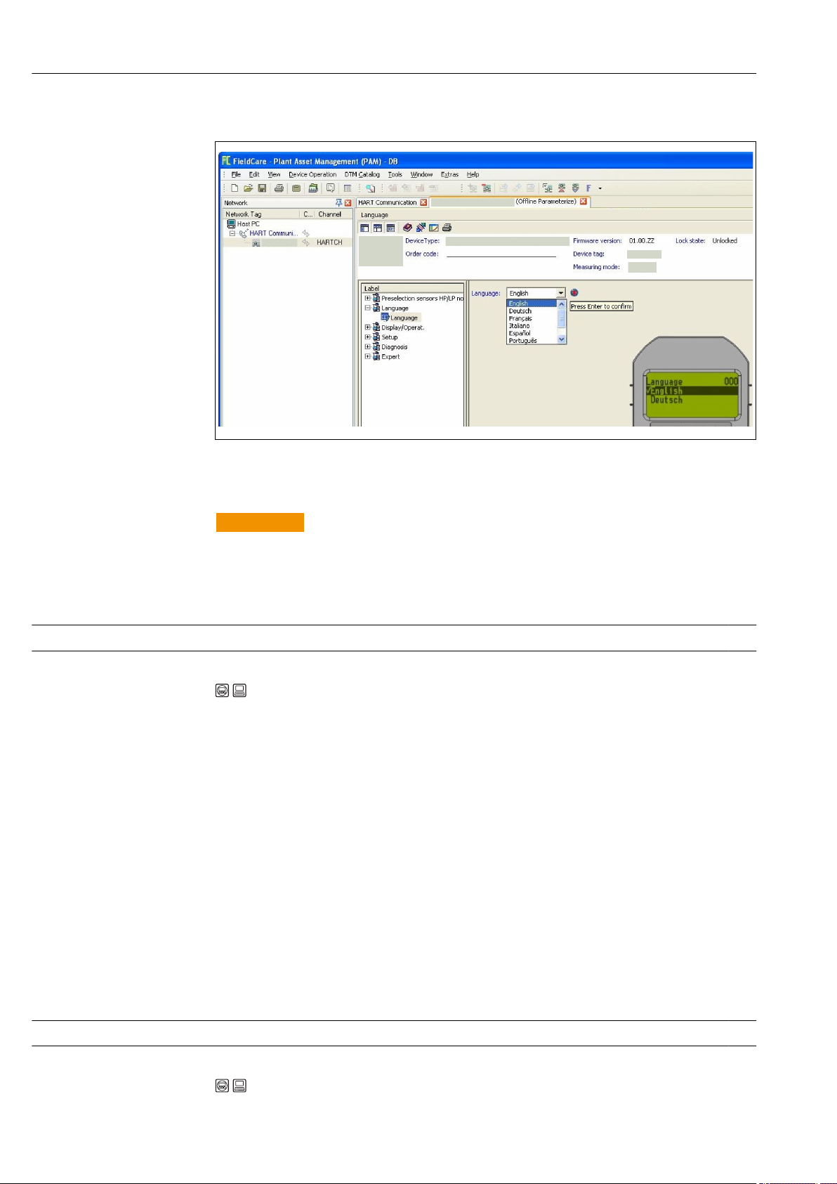
Commissioning Deltabar FMD71, FMD72
9.5.2 Configuring language via operating tool (FieldCare)
A0017654-EN
9.6 Measuring mode selection
WARNING
L
Changing the measuring mode affects the span (URV)
This situation can result in product overflow.
If the measuring mode is changed, the setting for the span (URV) must be checked in
‣
the "Setup" operating menu and readjusted if necessary.
Measuring mode (005)
Navigation Setup → Measuring mode
Write permission Operator/Service engineers/Expert
Description Select the measuring mode.
The operating menu is structured differently depending on the measuring mode selected.
Options • Pressure
• Level
Factory setting Level
9.7 Selecting the high-pressure side
9.7.1 Defining the high-pressure side
High press. side (183)
Navigation Setup → High press. side
46 Endress+Hauser
Page 47

Deltabar FMD71, FMD72 Commissioning
Write permission Operator/Service engineers/Expert
Description Define which sensor module corresponds to the high-pressure side.
Options • Sensor module HP
• Sensor module LP
Factory setting Sensor module HP
9.8 Pressure unit selection
Press. eng. unit (125)
Navigation Setup → Press. eng. unit
Write permission Operators/Service engineers/Expert
Description Select the pressure engineering unit. If a new pressure engineering unit is selected, all
pressure-specific parameters are converted and displayed with the new unit.
Options • mbar, bar
• mmH2O, mH2O
• in H2O, ftH2O
• Pa, kPa, MPa
• psi
• mmHg, inHg
• kgf/cm
Factory setting mbar, bar or psi depending on the sensor module nominal measuring range, or as per
order specifications.
2
9.9 Pos. zero adjust
The pressure resulting from the orientation of the device can be corrected here.
Corrected press. (172)
Navigation Setup → Corrected press.
Write permission Operators/Service engineers/Expert
Description Displays the measured pressure after the differential pressure buildup and position
adjustment.
Note If this value is not equal to "0", it can be corrected to "0" by the position adjustment.
Endress+Hauser 47
Page 48

Commissioning Deltabar FMD71, FMD72
Pos. zero adjust (007)
Navigation Setup → Pos. zero adjust
Write permission Operators/Service engineers/Expert
Description Position adjustment – the pressure difference between zero (set point) and the measured
differential pressure need not be known.
Options • Confirm
• Cancel
Example • Measured value = 2.2 mbar (0.033 psi)
• You correct the measured value via the "Pos. zero adjust" parameter with the "Confirm"
option. This means that you are assigning the value 0.0 to the pressure present.
• Measured value (after pos. zero adjust) = 0.0 mbar
• The current value is also corrected.
Factory setting Cancel
9.10 Configuring level measurement
9.10.1 Information on level measurement
You have a choice of two methods for calculating the level: "In pressure" and "In
height". The table in the "Overview of level measurement" section that follows
provides you with an overview of these two measuring tasks.
• The limit values are not checked, i.e. the values entered must be appropriate for the
sensor module and the measuring task for the device to be able to measure
correctly.
• Customer-specific units are not possible.
• There is no unit conversion.
• The values entered for "Empty calib./Full calib.", "Empty pressure/Full pressure",
"Empty height/Full height" and "Set LRV/Set URV" must be at least 1% apart. The
value will be rejected, and a warning message displayed, if the values are too close
together.
48 Endress+Hauser
Page 49

Deltabar FMD71, FMD72 Commissioning
A
B
9.10.2 Overview of level measurement
Measuring task Level
selection
Calibration is
performed by
entering two
pressure-level
value pairs.
Calibration is
performed by
entering the
density and two
height-level value
pairs.
"In
pressure"
"In height" • Calibration with
Measured variable
options
Via the "Unit before
lin. (025)" parameter
→ 86: %, level,
volume or mass
units.
Description Measured value display
• Calibration with
reference pressure
(wet calibration)
→ 49
• Calibration without
reference pressure
(dry calibration),
→ 51
reference pressure
(wet calibration)
→ 53
• Calibration without
reference pressure
(dry calibration),
→ 54
The measured value
display and the "Level
before lin (019)"
parameter → 84show
the measured value.
9.10.3 "In pressure" level selection Calibration with reference pressure (wet calibration)
Example:
In this example, the level in a tank should be measured in "m". The maximum level is
3 m (9.8 ft).
The pressure range is derived from the level and the density of the medium. In this
situation, the device sets the pressure range to 0 to 300 mbar (4.5 psi).
Prerequisite:
• The measured variable is in direct proportion to the pressure.
• The tank can be filled and emptied.
The values entered for "Empty calib./Full calib.", "Set LRV/Set URV", and the applied
pressures must be at least 1% apart. The value will be rejected, and a warning
message displayed, if the values are too close together. Further limit values are not
checked, i.e. the values entered must be appropriate for the sensor module and the
measuring task for the device to be able to measure correctly.
Description
1 Perform a "position adjustment" → 81.
2 Select the "Level" measuring mode via the
"Measuring mode (005)" parameter.
Menu path: Setup → Measuring mode
3 Select a pressure engineering unit via the
"Press eng. unit (125)" parameter, here "mbar"
for example.
Menu path: Setup → Press. eng. unit
4 Select the "In pressure" level mode via the
"Level selection (024)" parameter.
Menu path: Setup → Extended setup → Level →
Level selection
5 Select a level unit via the "Unit before lin.
(025)" parameter, here "m" for example.
Menu path: Setup → Extended setup → Level →
Unit before lin.
A0017661
A See table, step 7.
B See table, step 8.
Endress+Hauser 49
Page 50

Commissioning Deltabar FMD71, FMD72
A
B
C
D
h
[m]
I
[mA]
p
[mbar]
h
[m]
3
20
0
4
0
0
300
3
Description
6 Select the "Wet" option via the "Calibration
mode (027)" parameter.
Menu path: Setup → Extended setup → Level →
Calibration mode
7 The vessel is filled to the lower calibration
point. The pressure here is 0 mbar (0 psi), for
example.
Select the "Empty calib. (028)" parameter.
Menu path: Setup → Extended setup → Level →
Empty calib.
Enter the level value, here 0 m for example.
The pressure value present is assigned to the
lower level value by confirming the value.
8 The vessel is filled to the upper calibration
point. The pressure here is
300 mbar (4.35 psi), for example.
Select the "Full Calib. (031)" parameter.
Menu path: Setup → Extended setup → Level →
Full calib.
Enter the level value, here 3 m (9.8 ft) for
example. The pressure value present is
assigned to the upper level value by confirming
the value.
9 If calibration is performed with a medium
other than the process medium, enter the
density of the calibration medium in "Adjust
density (034)".
Menu path: Setup → Extended setup → Level →
Adjust density
10 Use the "Set LRV (166)" parameter to set the
level value for the lower current value (4 mA)
(0 m (0 ft)).
Menu path: Setup → Extended setup → Current
output → Set LRV
11 Use the "Set URV (167)" parameter to set the
level value for the upper current value (20 mA)
(3 m (9.8 ft)).
Menu path: Setup → Extended setup → Current
output → Set URV
12 If the process uses a medium other than that
on which the calibration was based, the new
density must be specified in the "Process
density (035)" parameter.
Menu path: Setup → Extended setup → Level →
Process density
13 Result:
The measuring range is configured for
0 to 3 m (0 to 9.8 ft).
C See table, step 7.
D See table, step 8.
E See table, step 10.
F See table, step 11.
h Height
i Current value
p Pressure
A0034735
For this level mode, the measured variables %, level, volume and mass are available,
see "Unit before lin. (025)"→ 86.
50 Endress+Hauser
Page 51

Deltabar FMD71, FMD72 Commissioning
A
B
9.10.4 "In pressure" level selection Calibration without reference pressure (dry calibration)
Example:
In this example, the volume in a tank should be measured in liters. The maximum volume
of 1 000 l (264 gal) corresponds to a pressure of 450 mbar (6.53 psi).
The minimum volume of 0 liters corresponds to a pressure of 50 mbar (0.73 psi) since the
device is mounted below the start of the level measuring range.
Prerequisite:
• The measured variable is in direct proportion to the pressure.
• This is a theoretical calibration i.e. the pressure and volume values for the lower and
upper calibration point must be known.
• The values entered for "Empty calib./Full calib.", "Empty pressure/Full pressure" and
"Set LRV/Set URV" must be at least 1% apart. The value will be rejected, and a
warning message displayed, if the values are too close together. Further limit values
are not checked, i.e. the values entered must be appropriate for the sensor module
and the measuring task for the device to be able to measure correctly.
• Due to the orientation of the device, there may be pressure shifts in the measured
value, i.e. when the vessel is empty or partly filled, the measured value is not zero.
For information on how to perform position adjustment, see → 81.
Description
1 Select the "Level" measuring mode via the
"Measuring mode (005)" parameter.
Menu path: Setup → Measuring mode
2 Select a pressure engineering unit via the
"Press eng. unit (125)" parameter, here "mbar"
for example.
Menu path: Setup → Press. eng. unit
3 Select the "In pressure" level mode via the
"Level selection (024)" parameter.
Menu path: Setup → Extended setup → Level →
Level selection
4 Select a volume unit via the "Unit before lin.
(025)" parameter, here "l" (liters) for example.
Menu path: Setup → Extended setup → Level →
Unit before lin.
A0017661
A See table, steps 6 and 7.
B See table, steps 8 and 9.
Endress+Hauser 51
Page 52
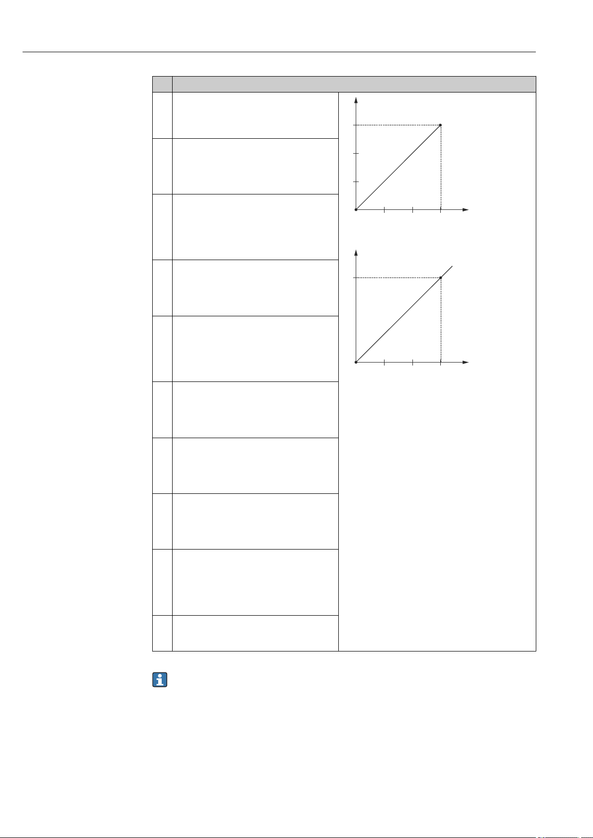
Commissioning Deltabar FMD71, FMD72
C
D
E
F
G
H
v
p
i
v
Description
5 Select the "Dry" option via the "Calibration
mode (027)" parameter.
Menu path: Setup → Extended setup → Level →
Calibration mode
6 Enter the volume value for the lower
calibration point via the "Empty calib. (028)"
parameter, here 0 liters for example.
Menu path: Setup → Extended setup → Level →
Empty calib.
7 Enter the pressure value for the lower
calibration point via the "Empty pressure
(029)" parameter, here 50 mbar (0.73 psi) for
example.
Menu path: Setup → Extended setup → Level →
Empty pressure
8 Enter the volume value for the upper
calibration point via the "Full calib. (031)"
parameter, here 1 000 l (264 gal) for example.
Menu path: Setup → Extended setup → Level →
Full calib.
9 Enter the pressure value for the upper
calibration point via the "Full pressure (032)"
parameter, here 450 mbar (6.53 psi) for
example.
Menu path: Setup → Extended setup → Level →
Full pressure
10 "Adjust density (034)" contains the factory
setting 1.0, but this value can be changed if
required.
Menu path: Setup → Extended setup → Level →
Adjust density
11 Set the volume value for the lower current
value (4 mA) via the "Set LRV (166)"
parameter (0 l).
Menu path: Setup → Extended setup → Current
output → Set LRV
12 Set the volume value for the upper current
value (20 mA) via the "Set URV (167)"
parameter (1 000 l (264 gal)).
Menu path: Setup → Extended setup → Current
output → Set URV
13 If the process uses a medium other than that
on which the calibration was based, the new
density must be specified in the "Process
Density" parameter.
Menu path: Setup → Extended setup → Current
output → Process density.
14 Result:
The measuring range is configured for
0 to 1 000 l (0 to 264 gal).
C See table, step 6.
D See table, step 7.
E See table, step 8.
F See table, step 9.
G See table, step 11
H See table, step 12
i Current value
p Pressure
v Volume
A0034736
For this level mode, the measured variables %, level, volume and mass are available,
see "Unit before lin. (025)" → 86.
52 Endress+Hauser
Page 53

Deltabar FMD71, FMD72 Commissioning
A
B
9.10.5 "In height" level selection Calibration with reference pressure (wet calibration)
Example:
In this example, the volume in a tank should be measured in liters. The maximum volume
of 1 000 l (264 gal) corresponds to a level of 4.5 m (15 ft).
The minimum volume of 0 liters corresponds to a level of 0.5 m (1.6 ft) since the device is
mounted below the start of the level measuring range. The density of the fluid is 1 g/cm
(1 SGU).
Prerequisite:
• The measured variable is in direct proportion to the pressure.
• The tank can be filled and emptied.
The values entered for "Empty Calib./Full Calib.", "Set LRV/Set URV", and the applied
pressure values must be at least 1% apart. The value will be rejected, and a warning
message displayed, if the values are too close together. Further limit values are not
checked, i.e. the values entered must be appropriate for the sensor module and the
measuring task for the device to be able to measure correctly.
3
Description
1 Select the "Level" measuring mode via the
"Measuring mode (005)" parameter.
Menu path: Setup → Measuring mode
2 Select a pressure engineering unit via the
"Press eng. unit (125)" parameter, here "mbar"
for example.
Menu path: Setup → Press. eng. unit
3 Select the "In height" level mode via the "Level
selection (024)" parameter.
Menu path: Setup → Extended setup → Level →
Level selection
4 Select a volume unit via the "Unit before lin.
(025)" parameter, here "l" (liters) for example.
Menu path: Setup → Extended setup → Level →
Unit before lin.
A0017661
A See table, step 8.
B See table, step 9.
Endress+Hauser 53
Page 54

Commissioning Deltabar FMD71, FMD72
h
p
v
h
i
v
C
D
E
F
G
Description
5 Select a level unit via the "Height unit (026)"
parameter, here "m" for example.
Menu path: Setup → Extended setup → Level →
Height unit
6 Select the "Wet" option via the "Calibration
mode (027)" parameter.
Menu path: Setup → Extended setup → Level →
Calibration mode
7 Vessel is filled up to 0.5 m (1.6 ft), (49 mbar
(0.72 psi)).
Enter the volume value for the lower
calibration point via the "Empty calib. (028)"
parameter, here 0 liters for example.
Menu path: Setup → Extended setup → Level →
Empty calib.
8 Vessel is filled up to 4.5 m (15 ft), (441 mbar
(6.40 psi)).
Enter the volume value for the upper
calibration point via the "Full calib. (031)"
parameter, here 1 000 l (264 gal) for example.
Menu path: Setup → Extended setup → Level →
Full calib.
9 Enter the density of the calibration medium in
"Adjust density (034)", here 1 g/cm3 (1 SGU),
for example.
Menu path: Setup → Extended setup → Level →
Adjust density
10 Set the volume value for the lower current
value (4 mA) via the "Set LRV (166)" parameter
(0 l).
Menu path: Setup → Extended setup → Current
output → Set LRV
11 Set the volume value for the upper current
value (20 mA) via the "Set URV (167)"
parameter 1 000 l (264 gal).
Menu path: Setup → Extended setup → Current
output → Set URV
12 If the process uses a medium other than that
on which the calibration was based, the new
density must be specified in the "Process
density (035)" parameter.
Menu path: Setup → Extended setup → Level →
Process density
13 Result:
The measuring range is configured for
0 to 1 000 l (0 to 264 gal).
C See table, step 10.
D See table, step 8.
E See table, step 9.
F See table, step 11.
G See table, step 12.
h Height
i Current value
p Pressure
v Volume
A0034737
For this level mode, the measured variables %, level, volume and mass are available,
see "Unit before lin. (025)" → 86.
9.10.6 "In height" level selection Calibration without reference pressure (dry calibration)
Example:
54 Endress+Hauser
In this example, the volume in a tank should be measured in liters. The maximum volume
of 1 000 l (264 gal) corresponds to a level of 4.5 m (15 ft). The minimum volume of 0
Page 55
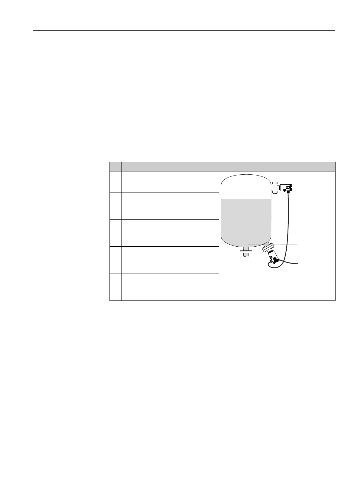
Deltabar FMD71, FMD72 Commissioning
A
B
liters corresponds to a level of 0.5 m (1.6 ft) since the device is mounted below the start of
the level measuring range.
Prerequisite:
• The measured variable is in direct proportion to the pressure.
• This is a theoretical calibration i.e. the height and volume values for the lower and upper
calibration point must be known.
• The values entered for "Empty calib./Full calib.", "Empty height/Full height" and "Set
LRV/Set URV" must be at least 1% apart. The value will be rejected, and a warning
message displayed, if the values are too close together. Further limit values are not
checked, i.e. the values entered must be appropriate for the sensor module and the
measuring task for the device to be able to measure correctly.
• Due to the orientation of the device, there may be pressure shifts in the measured value,
i.e. when the vessel is empty or partly filled, the measured value is not zero. For
information on how to perform position adjustment, see → 81.
Description
1 Select the "Level" measuring mode via the
"Measuring mode (005)" parameter.
Menu path: Setup → Measuring mode
2 Select a pressure engineering unit via the
"Press eng. unit (125)" parameter, here "mbar"
for example.
Menu path: Setup → Press. eng. unit
3 Select the "In height" level mode via the "Level
selection (024)" parameter.
Menu path: Setup → Extended setup → Level →
Level selection
4 Select a volume unit via the "Unit before lin.
(025)" parameter, here "l" (liters) for example.
Menu path: Setup → Extended setup → Level →
Unit before lin.
5 Select a level unit via the "Height unit (026)"
parameter, here "m" for example.
Menu path: Setup → Extended setup → Level →
Height unit
A See table, steps 7 and 8.
B See table, steps 9 and 10.
A0017661
Endress+Hauser 55
Page 56

Commissioning Deltabar FMD71, FMD72
h
p
v
h
i
v
C
D
E
F
G
Description
6 Select the "Dry" option via the "Calibration mode
(027)" parameter.
Menu path: Setup → Extended setup → Level →
Calibration mode
7 Enter the volume value for the lower
calibration point via the "Empty calib. (028)"
parameter, here 0 liters for example.
Menu path: Setup → Extended setup → Level →
Empty calib.
8 Enter the height value for the lower calibration
point via the "Empty height (030)" parameter,
here 0.5 m (1.6 ft) for example.
Menu path: Setup → Extended setup → Level →
Empty height
9 Enter the volume value for the upper
calibration point via the "Full calib. (031)"
parameter, here 1 000 l (264 gal) for example.
Menu path: Setup → Extended setup → Level →
Full calib.
10 Enter the height value for the upper calibration
point via the "Full height (033)" parameter,
here 4.5 m (15 ft) for example.
Menu path: Setup → Extended setup → Level →
Full height
11 Enter the density of medium via the "Adjust
density (034)" parameter, here "1 g/cm3" (1
SGU) for example.
Menu path: Setup → Extended setup → Level →
Adjust density
12 Set the volume value for the lower current
value (4 mA) via the "Set LRV (166)" parameter
(0 l).
Menu path: Setup → Extended setup → Current
output → Set LRV
13 Set the volume value for the upper current
value (20 mA) via the "Set URV (167)"
parameter 1 000 l (264 gal)).
Menu path: Setup → Extended setup → Current
output → Set URV
13 If the process uses a medium other than that
on which the calibration was based, the new
density must be specified in the "Process
density" parameter.
Menu path: Setup → Extended setup → Current
output → Process density.
14 Result:
The measuring range is configured for
0 to 1 000 l (0 to 264 gal).
C See table, step 11.
D See table, step 7.
E See table, step 9.
F See table, step 12.
G See table, step 13.
h Height
i Current value
p Pressure
v Volume
A0034737
For this level mode, the measured variables %, level, volume and mass are available,
see "Unit before lin. (025)" → 86.
9.10.7 Calibration with partially filled vessel (wet calibration)
Example:
56 Endress+Hauser
This example explains a wet calibration for cases in which it is not possible to empty the
vessel and then fill it to 100%.
Page 57

Deltabar FMD71, FMD72 Commissioning
B
A
During this wet calibration, a level of 20% is used as the calibration point for "Empty" and a
level of "80%" is used as the calibration point for "Full".
The calibration is then extended to 0% to 100% and lower range-value (LRV)/upper
range-value (URV) are adapted accordingly.
Prerequisite:
• The default value in level mode for the calibration mode is "Wet".
• This value can be adjusted: Menu path: Setup → Extended setup → Level → Calibration
mode
Description
1 Select the "Level" measuring mode via the
"Measuring mode (005)" parameter.
Menu path: Setup → Measuring mode
2 Select a unit via the "Unit before lin. (025)"
parameter, here "%" for example.
Menu path: Setup → Extended setup → Level→
Unit before lin.
3 20% of the vessel is full. Enter the level value
for the lower calibration value via the "Empty
calib. (028)" parameter, here 20% for example.
Menu path: Setup → Extended setup → Level →
Empty calib.
4 80% of the vessel is full. Enter the level value
for the upper calibration value via the "Full
calib. (031)" parameter, here 80% for example.
Menu path: Setup → Extended setup → Level →
Full calib.
5 The pressure values for full/empty calibration
are automatically recorded and applied. The
upper range value (URV) and lower range
value (LRV) automatically accept the values
that were entered in "Empty calib. (028)" and
"Full calib. (031)". These automatically entered
values can be edited if necessary and, for
example, changed to a value ranging from 0 to
100%.
A0017668
A See table, step 3
B See table, step 4
If the process uses a medium other than that on which the calibration was based,
the new density must be specified in the "Process density (035)" parameter. In
this case, you have to enter the various densities via the following menu path:
• Setup → Extended setup → Level → Adjust density (034) e.g. 1.0 kg/l for water)
• Setup → Extended setup → Level → Process density (035) e.g. 0.8 kg/l for oil)
Endress+Hauser 57
Page 58
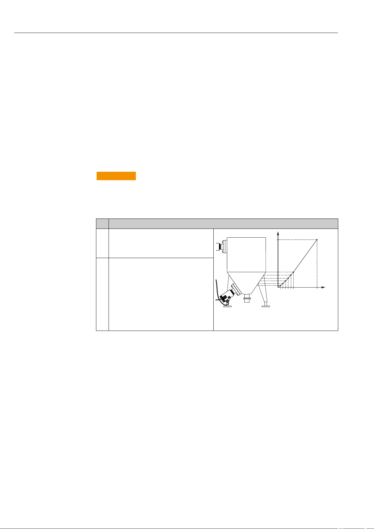
Commissioning Deltabar FMD71, FMD72
v
h
9.11 Linearization
9.11.1 Manual entry of a linearization table
Example:
In this example, the volume in a tank with a conical outlet should be measured in m3.
Prerequisite:
• This is a theoretical calibration, i.e. the points for the linearization table are known.
• The "Level" measuring mode has been selected.
• A level calibration has been performed.
• The linearization characteristic must rise or fall continuously.
• For a description of the parameters mentioned, → 78"Description of parameters".
WARNING
L
Changing the measuring mode affects the span (URV)
This situation can result in product overflow.
If the measuring mode is changed, the setting for the span (URV) must be checked in
‣
the "Setup" operating menu and readjusted if necessary.
Description
1 Select the "Manual entry" option via the "Lin.
mode (037)" parameter.
Menu path: Setup → Extended setup →
Linearization → Lin. mode
2 Select using the "Unit after lin. (038)"
parameter, e.g. m3.
Menu path: Setup → Extended setup →
Linearization → Unit after lin.
A0017669
h Height
v Volume
58 Endress+Hauser
Page 59

Deltabar FMD71, FMD72 Commissioning
v
h
i
v
Description
3 Enter the number of the point in the table
using the "Line number (039)" parameter e.g. 1.
Menu path: Setup → Extended setup →
Linearization → Line numb.
The level is entered via the "X-value (040)"
parameter, here 0 m for example. Confirm your
entry.
Menu path: Setup → Extended setup →
Linearization → X-value
Using the "Y-val. (041)" parameter, enter the
corresponding volume value, here 0 m3 for
example, and confirm the value.
Menu path: Setup → Extended setup →
Linearization → Y-value
4 To enter another point in the table, select the
"Next point" option via the "Edit table (042)"
parameter. Enter the next point as explained in
Step 3.
Menu path: Setup → Extended setup →
Linearization → Edit table
5 Once all the points have been entered in the
table, select the "Activate table" option via the
"Lin. mode (037)" parameter.
Menu path: Setup → Extended setup →
Linearization → Lin. mode
6 Result:
Result: The measured value after linearization
is displayed.
h Height
i Current value
v Volume
A0017670
• Error message F510 "Linearization" and alarm current as long as the table is being
entered and until the table is activated.
• Error message F511/F512 "Linearization" and alarm current as long as the
linearization table consists of fewer than 2 points.
• The lower range value (= 4mA) is defined by the smallest point in the table.
The upper range value (= 20mA) is defined by the greatest point in the table.
• Using the parameters "Set LRV" and "Set URV", you can change the allocation of the
volume/mass values to the current values.
9.11.2 Manual entry of a linearization table via operating tool
With an operating tool based on FDT technology (e.g. FieldCare), it is possible to enter
linearization via a module that has been specially designed for this. This provides you with
an overview of the selected linearization, even during entry. In addition, it is possible to
configure different tank shapes in FieldCare ("Device operation" → "Device functions" →
"Additional functions" → "Linearization table" menu).
The linearization table may also be entered manually point by point in the operating
tool menu (see section → 78).
9.11.3 Semi-automatic entry of a linearization table
Example:
In this example, the volume in a tank with a conical outlet should be measured in m3.
Endress+Hauser 59
Page 60
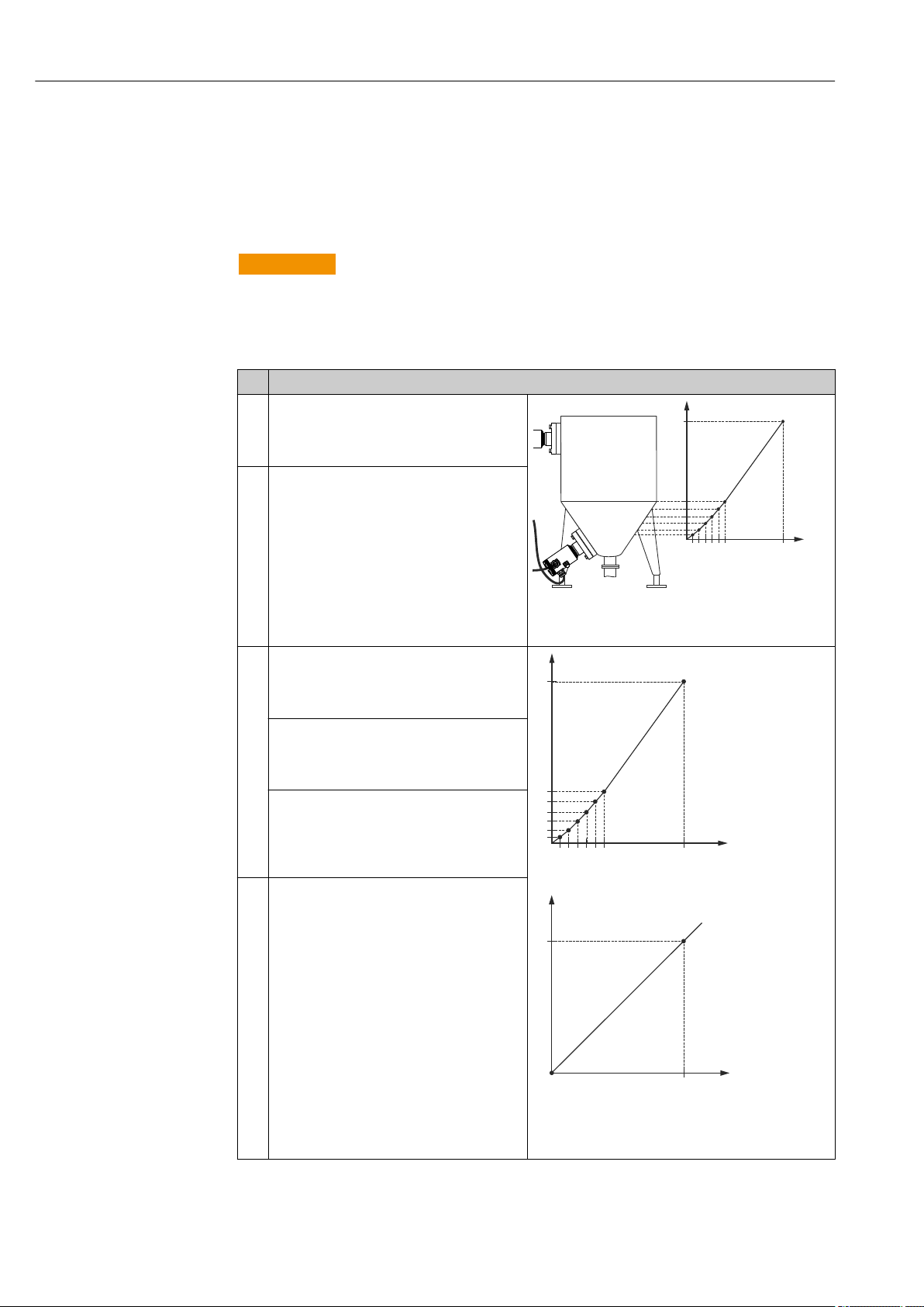
Commissioning Deltabar FMD71, FMD72
v
h
v
h
i
v
Prerequisite:
• The tank can be filled or emptied. The linearization characteristic must rise or fall
continuously.
• The "Level" measuring mode has been selected.
• A level calibration has been performed.
• For a description of the parameters mentioned, → 78"Description of parameters".
WARNING
L
Changing the measuring mode affects the span (URV)
This situation can result in product overflow.
If the measuring mode is changed, the setting for the span (URV) must be checked in
‣
the "Setup" operating menu and readjusted if necessary.
Description
1 Select the "Semiautom. entry" option via the
"Lin. mode (037)" parameter.
Menu path: Setup → Extended setup →
Linearization → Lin. mode
2 Select using the "Unit after lin. (038)"
parameter, e.g. m3.
Menu path: Setup → Extended setup →
Linearization → Unit after lin.
A0017669
h Height
v Volume
3 Enter the number of the point in the table
using the "Line number (039)" parameter e.g. 1.
Menu path: Setup → Extended setup →
Linearization → Line numb.
The level at the current time is displayed using
the "X-value (040)" parameter.
Menu path: Setup → Extended setup →
Linearization → X-value
Using the "Y-val. (041)" parameter, enter the
corresponding volume value, here 0 m3 for
example, and confirm the value.
Menu path: Setup → Extended setup →
Linearization → Y-value
4 To enter another point in the table, continue
filling the tank and select the "Next point"
option. via the "Edit table (042)" parameter.
Enter the next point as explained in Step 3.
Menu path: Setup → Extended setup →
Linearization → Edit table
60 Endress+Hauser
h Height
i Current value
v Volume
A0017670
Page 61

Deltabar FMD71, FMD72 Commissioning
i
p
A
B
Description
5 Once all the points have been entered in the
table, select the "Activate table" option via the
"Lin. mode (037)" parameter.
Menu path: Setup → Extended setup →
Linearization → Lin. mode
6 Result:
Result: The measured value after linearization
is displayed.
• Error message F510 "Linearization" and alarm current as long as the table is being
entered and until the table is activated.
• The lower range value (= 4mA) is defined by the smallest point in the table.
The upper range value (= 20mA) is defined by the greatest point in the table.
• Using the parameters "Set LRV" and "Set URV", you can change the allocation of the
volume/mass values to the current values.
9.12 Configuring pressure measurement
9.12.1 Calibration without reference pressure (dry calibration)
Example:
In this example, a device with a 400 mbar (6 psi) sensor module is configured for the 0 to
+300 mbar (4.4 psi) measuring range, i.e. the 4 mA value and the 20 mA value are
assigned 0 mbar and 300 mbar (4.4 psi) respectively.
Prerequisite:
This is a theoretical calibration, i.e. the pressure values for the lower and upper range are
known. It is not necessary to apply pressure.
Due to the orientation of the device, there may be pressure shifts in the measured
value, i.e. the measured value is not zero in a pressureless condition. For information
on how to perform position adjustment, see "Position adjustment" section → 47.
Description
1 Select the "Pressure" measuring mode via the
"Measuring mode (005)" parameter.
Menu path: Setup → Measuring mode
2 Select a pressure engineering unit via the
"Press eng. unit (125)" parameter, here "mbar"
for example.
Menu path: Setup → Press. eng. unit
3 Select "Set LRV (013)" parameter.
Menu path: Setup → Set LRV
Enter and confirm the value (here 0 mbar (0
psi)) for the "Set LRV" parameter. This pressure
value is assigned to the lower current value (4
mA).
4 Select the "Set URV (014)" parameter.
Menu path: Setup → Set URV
A See table, step 3.
B See table, step 4.
i Current value
p Pressure
A0017671
Endress+Hauser 61
Page 62

Commissioning Deltabar FMD71, FMD72
Description
Enter and confirm the value (here 300 mbar
(4.5 psi)) for the "Set URV (014)" parameter.
This pressure value is assigned to the upper
current value (20 mA).
5 Result:
The measuring range is configured for 0 to
+300 mbar (4.5 psi).
62 Endress+Hauser
Page 63

Deltabar FMD71, FMD72 Commissioning
i
p
A
B
9.12.2 Calibration with reference pressure (wet calibration)
Example:
In this example, a device with a 400 mbar (6 psi) sensor module is configured for the 0 to
+300 mbar (4.4 psi) measuring range, i.e. the 4 mA value and the 20 mA value are
assigned 0 mbar and 300 mbar (4.4 psi) respectively.
Prerequisite:
The pressure values 0 mbar and 300 mbar (4.4 psi) can be specified. The device is already
mounted, for example.
For a description of the parameters mentioned, → 78"Description of parameters".
Description
1 Perform position adjustment → 81.
2 Select the "Pressure" measuring mode via the
"Measuring mode (005)" parameter.
Menu path: Setup → Measuring mode
3 Select a pressure engineering unit via the
"Press Eng. Unit (125)" parameter, here "mbar"
for example.
Menu path: Setup → Press. eng. unit
4 The pressure for the LRV (4 mA value) is
present at the device, here 0 mbar (0 psi) for
example.
Select the "Get LRV (015)" parameter.
Menu path: Setup → Extended setup → Current
output → Get LRV.
Confirm the value present by selecting "Apply".
The pressure value present is assigned to the
lower current value (4 mA).
5 The pressure for the URV (20 mA value) is
present at the device, here 300 mbar (4.4 psi)
for example.
Select the "Get URV (016)" parameter.
Menu path: Setup → Extended setup → Current
output → Get URV.
Confirm the value present by selecting "Apply".
The pressure value present is assigned to the
upper current value (20 mA).
6 Result:
The measuring range is configured for 0 to
+300 mbar (4.5 psi).
A See table, step 4.
B See Table, Step 5.
i Current value
p Pressure
A0017671
9.13 Backing up or duplicating the device data
The following options are available to you with an operating tool that is based on FDT
technology (e.g. FieldCare):
• Storage/recovery of configuration data.
Download select. (visible only in FieldCare)
Endress+Hauser 63
• Duplication of device parameters.
• Transfer of all relevant parameters when replacing electronic inserts.
Use the following parameter for this:
Page 64

Commissioning Deltabar FMD71, FMD72
Navigation Expert → System → Management → Download select.
Write permission Operators/Service engineers/Expert
Description Selection of data packages for up/download function in Fieldcare and PDM.
Prerequisite DIP switch set to "SW" and "Damping" set to "on". If you download using the factory setting
"Configuration copy", all parameters required for a measurement will be downloaded. The
functionality of the "Electronics replace" setting is reserved for Endress+Hauser Service and
can be accessed only if the correct device access code is entered.
Options • Configuration copy: This option overwrites general configuration parameters with the
exception of the serial number, order number, calibration, pos. zero adjust, application
and day information.
• Device replacement: This option overwrites general configuration parameters with the
exception of the serial number, order number, calibration and position adjustment.
• Electronics replace: This option overwrites general configuration parameters.
Factory setting Copy configuration
9.14 Configuring the local display
9.14.1 Adjusting the local display
The local display can be adjusted in the following menu:
Display/operat. → 74
9.15 Protecting settings from unauthorized access
The settings can be protected from unauthorized access in two ways:
• Locking via write protection switch (hardware locking) → 30
• Locking via parameter (software locking) → 37
64 Endress+Hauser
Page 65

Deltabar FMD71, FMD72 Diagnostics and troubleshooting
10 Diagnostics and troubleshooting
10.1 Troubleshooting
General errors
Problem Possible cause Solution
Device is not responding. Supply voltage does not match the
value indicated on the nameplate.
The polarity of the supply voltage is
wrong.
Connecting cables are not in contact
with the terminals.
No display Onsite display is set too bright or too
dark.
Connector for onsite display is not
properly connected.
Onsite display is defective. Replace onsite display.
Output current < 3.6 mA Signal line is not wired correctly.
Electronics unit is defective.
Device measures
incorrectly.
HART communication is not
working.
Configuration error. Check and correct parameter
Communication resistor missing or
incorrectly installed.
Commubox is connected incorrectly. Connect Commubox correctly.
Commubox is not set to "HART". Set Commubox selector switch to
Apply correct voltage.
Correct the polarity.
Check the connection of the cables and
correct if necessary.
• Set the onsite display brighter by
simultaneously pressing and .
• Set the onsite display darker by
simultaneously pressing and .
Connect the plug correctly.
Check wiring.
Replace electronics.
configuration (see below).
Install the communication resistor (250
Ω) correctly.
"HART".
10.2 Diagnostic events
10.2.1 Diagnostic message
Faults detected by the self-monitoring system of the measuring device are displayed as a
diagnostic message in alternation with the measured value display.
Status signals
The table → 66 lists the messages that may occur. The ALARM STATUS parameter
shows the message with the highest priority. The device has four different status
information codes according to NAMUR NE107:
"Failure"
A device error has occurred. The measured value is no longer valid.
A0013956
"Maintenance required"
Maintenance is required. The measured value remains valid.
A0013957
"Function check"
The device is in service mode (e.g. during a simulation).
A0013959
"Out of specification"
The device is operated:
• Outside its technical specifications (e.g. during warm-up or cleaning).
A0013958
• Outside of the configuration carried out by the user (e.g. level outside configured span)
Endress+Hauser 65
Page 66

Diagnostics and troubleshooting Deltabar FMD71, FMD72
Diagnostic event and event text
The fault can be identified by means of the diagnostic event.
The event text helps you by providing information on the fault.
Diagnostic event
Status signal Event number Event text
↓ ↓ ↓
Example
A0013958
841 Sensor range
3-digit number
If two or more diagnostic events are pending simultaneously, only the diagnostic message
with the highest priority is shown.
Other diagnostic messages that are pending can be viewed in the Diagnostic list submenu
→ 100.
Past diagnostic messages that are no longer pending are shown in the Event logbook
submenu→ 100.
10.2.2 List of diagnostic events
General messages
Diagnostic event Cause Corrective measure
Code Description
0 No error - -
"F" messages
Diagnostic event Cause Corrective measure
Code Description
F002 Sens. unknown
LP/HP
F062 Sensor conn. • Electromagnetic effects are greater than
F081 Initialization • Electromagnetic effects are greater than
F083 Permanent mem.
LP/HP
F140 Working range P
LP/HP
Sensor module does not suit the device (electronic
sensor module nameplate).
specifications in the technical data. This message
appears for a short time only.
• Sensor module defective.
• Cable connection between sensor module and
main electronics disconnected.
specifications in the technical data. This message
appears for a short time only.
• Sensor module defective.
• Cable connection between sensor module and
main electronics disconnected.
• Electromagnetic effects outside the permitted
range. This message appears for a short time only.
• Sensor module defective.
• Overpressure and low pressure present.
• Electromagnetic effects outside the permitted
range.
• Sensor module defective.
Contact Endress+Hauser
Service
• Contact Endress+Hauser
Service
• Replace electronics
• Check the sensor module
cable
• Contact Endress+Hauser
Service
• Check sensor cable
• Perform a reset
• Contact Endress+Hauser
Service
• Restart device
• Check the process pressure
• Check sensor module
range
66 Endress+Hauser
Page 67

Deltabar FMD71, FMD72 Diagnostics and troubleshooting
Diagnostic event Cause Corrective measure
Code Description
F162 Sensor conn. • Sensor module defective (master).
• Electromagnetic effects outside the permitted
range. This message appears for a short time only.
F162 Sensor conn. HP
Sensor conn. LP
F163 Sensor conn. • Cable connection between sensor modules HP and
F164 Sensor sync. • The sensor modules cannot be synchronized with
F165 Sensor
assignment
F261 Electronics
module
F282 Memory • Main electronics defective.
F283 Memory content • Main electronics defective.
F411 Up-/Download • The file is defective.
F510 Linearization The linearization table is being edited. • Conclude entries
F511 Linearization The linearization table consists of less than 2 points. • Table too small
F512 Linearization The linearization table is not monotonic increasing
F841 Sensor range • Overpressure or low pressure present.
F882 Input signal External measured value is not received or displays a
F945 Pressure limit LP • The configured overpressure or underpressure
• Electromagnetic effects outside the permitted
range. This message appears for a short time only.
• Sensor module defective.
LP interrupted.
• Sensor module defective (slave).
• Electromagnetic effects outside the permitted
range. This message appears for a short time only.
each other.
• Electromagnetic effects outside the permitted
range. This message appears for a short time only.
• Sensor module(s) defective.
The assignment of the transmitter to sensor module
LP or HP is unknown (e.g. after changing the sensor
module). See also "Replacing sensor modules".
• Main electronics defective.
• Fault in the main electronics.
• Sensor module defective.
• Fault in the main electronics.
• Electromagnetic effects are greater than
specifications in the technical data.
• The supply voltage is disconnected when writing.
• An error occurred when writing.
• During the download, the data are not correctly
transmitted to the processor, e.g. because of open
cable connections, spikes (ripple) on the supply
voltage or electromagnetic effects.
or decreasing.
• Sensor module defective.
failure status.
limit of sensor module LP is exceeded.
• Sensor module LP defective.
• Check the sensor module
cable
• Replace sensor module
• Contact Endress+Hauser
Service
• Check the sensor module
cable
• Replace sensor module
• Contact Endress+Hauser
Service
• Restart device
• Check the sensor module
cable
• Contact Endress+Hauser
Service
• Restart device
• Replace sensor module
• Contact Endress+Hauser
Service
• Connect transm. set.
• Restart device
• Contact Endress+Hauser
Service
• Restart device
• Replace electronics
• Replace electronics
• Restart device
• Perform a reset
• Replace electronics
• Download again
• Use another file
• Perform a reset
• Select "linear"
• Corr. table
• Accept the table
• Tab. not monotonic
• Corr. table
• Accept the table
• Check the pressure value
• Contact Endress+Hauser
Service
• Check the bus
• Check source device
• Check the setting
• Check the pressure value
• Change pressure limit
value
• Contact Endress+Hauser
Service
Endress+Hauser 67
Page 68

Diagnostics and troubleshooting Deltabar FMD71, FMD72
"M" messages
Diagnostic event Cause Corrective measure
Code Description
M002 Sens. unknown Sensor module does not suit the device (electronic
sensor module nameplate). Device continues
measuring.
M283 Memory
content
M431 Adjustment The adjustment performed would cause the sensor
M434 Scaling • Values for adjustment (e.g. lower range value and
M438 Data set • The supply voltage is disconnected when writing.
• Cause as indicated for F283.
• Correct measurement can continue as long as you do
not need the peakhold indicator function.
nominal range to be exceeded or undershot.
upper range value) are too close together.
• Lower-range value and/or upper-range value exceed
or fall below the range limits of the sensor.
• The sensor was replaced and the customer-specific
configuration does not suit the sensor module.
• Unsuitable download carried out.
• An error occurred when writing.
Contact Endress+Hauser
Service
• Perform a reset
• Replace electronics
• Check the measuring
range
• Check position
adjustment
• Check the setting
• Check the measuring
range
• Check the setting
• Contact Endress+Hauser
Service
• Check the setting
• Restart device
• Replace electronics
"C" messages
Diagnostic event Cause Corrective measure
Code Description
C412 Backup in prog. Downloading. Wait for download to
complete.
C482 Simul. output Simulation of the current output is switched on, i.e. the
device is not measuring at present.
C484 Error simul. Fault state simulation is switched on, i.e. the device is
not measuring at present.
C824 Process pressure • Electromagnetic effects outside the permitted range.
This message appears for a short time only.
• Overpressure or low pressure present.
End the simulation
End the simulation
• Check the pressure value
• Restart device
• Perform a reset
"S" messages
Diagnostic event Cause Corrective measure
Code Description
S110 Operational
range T
S140 Working range P
LP/HP
S822 Process temp.
LP/HP
• Electromagnetic effects outside the permitted
range.
• Sensor module defective.
• Overpressure or low pressure present.
• Electromagnetic effects outside the permitted
range.
• Sensor module defective.
• The temperature measured in the sensor module
is greater than the upper nominal temperature
of the sensor module.
• The temperature measured in the sensor module
is smaller than the lower nominal temperature
of the sensor module.
• Check the process pressure
• Check the temperature
range
• Check the process pressure
• Check the pressure value
• Check temperature
• Check the setting
68 Endress+Hauser
Page 69

Deltabar FMD71, FMD72 Diagnostics and troubleshooting
Diagnostic event Cause Corrective measure
Code Description
S841 Sensor range • Overpressure or low pressure present.
• Sensor module defective.
S945 Pressure limit LP • The configured overpressure or underpressure
limit of the sensor module LP is exceeded.
• Sensor module LP defective.
S971 Adjustment • The current is outside the permitted range 3.8 to
20.5 mA.
• The present pressure value is outside the
configured measuring range (but within the
sensor module range, if applicable).
• Check the pressure value
• Contact Endress+Hauser
Service
• Check the pressure value
• Change pressure limit value
• Contact Endress+Hauser
Service
• Check the pressure value
• Check the measuring range
• Check the setting
10.3 Response of output to errors
The response of the current output to errors is defined in the following parameters:
• "Alarm behav. P (050)" → 93
• "Output fail mode (190)" → 94
• "High alarm curr. (052)" → 94
Endress+Hauser 69
Page 70

Diagnostics and troubleshooting Deltabar FMD71, FMD72
10.4 Firmware history
Date Firmware version Modifications Documentation
Operating Instructions Description of Device Parameters
01.2012 01.00.00 Original firmware.
Can be operated via FieldCare from version 2.08.00
BA01044P/00/EN/01.12 GP01013P/00/EN/01.12
BA01044P/00/EN/02.12 GP01013P/00/EN/02.12
BA01044P/00/EN/03.12 GP01013P/00/EN/03.12
BA01044P/00/EN/04.12 GP01013P/00/EN/04.12
BA01044P/00/EN/05.17 GP01013P/00/EN/05.17
10.5 Disposal
When disposing, separate and recycle the device components based on the materials.
70 Endress+Hauser
Page 71

Deltabar FMD71, FMD72 Maintenance
1
1
1
11 Maintenance
No special maintenance work is required.
Keep the pressure compensation and GORE-TEX® filter (1) free from contamination.
A0017750
11.1 Information on cleaning
Endress+Hauser provides flushing rings as an accessory to enable cleaning of the process
isolating diaphragm without removing the transmitter from the process.
For further information please contact your local Endress+Hauser Sales Center.
11.2 Exterior cleaning
Please note the following points when cleaning the device:
• The cleaning agents used should not corrode the surface and the seals.
• Mechanical damage to the process isolating diaphragm, e.g. due to sharp objects, must
be avoided.
• Observe the degree of protection of the device. See the nameplate if necessary → 15.
Endress+Hauser 71
Page 72

Repairs Deltabar FMD71, FMD72
12 Repairs
12.1 General notes
12.1.1 Repair concept
The Endress+Hauser repair concept requires for devices to have a modular design and for
repairs to be carried out by Endress+Hauser Service or by properly trained customers.
Spare parts are grouped into logical kits with the associated replacement instructions.
For more information on service and spare parts, please contact Endress+Hauser Service.
12.1.2 Repair of Ex-certified devices
When repairing Ex-certified devices, please also note the following:
• Only specialist personnel or Endress+Hauser-Service can carry out repairs to Ex certified
devices.
• Relevant standards and national regulations as well as safety instructions (XA) and
certificates must be observed.
• Only genuine Endress+Hauser spare parts may be used.
• When ordering spare parts, please check the device designation on the nameplate.
Identical parts may only be used as replacements.
• Carry out repairs according to the instructions. Following a repair, the device must fulfill
the requirements of the individual tests specified for that device.
• A certified device may be converted to another certified device version by Endress
+Hauser Service only.
• All repairs and modifications must be documented.
12.1.3 Replacing sensor modules or main electronics
Once both sensor modules or the main electronics have been replaced, the sensor
module that is connected to the transmitter must be selected. To do this, follow these
steps:
1. Switch off the supply voltage
2. Replacing the sensor module or main electronics
3. Switch on the supply voltage.
4. Select sensor module LP or sensor module HP: Menu path: Expert → System →
Management → Transm. connect. (286)"
For additional information, see "Function" → 13 section.
12.1.4 Replacing a device
Once a complete device has been replaced, the parameters can be transferred back into the
device using FieldCare:
Prerequisite: The configuration of the old device was saved previously to the computer
using FieldCare.
You can continue to measure without performing a new calibration.
72 Endress+Hauser
Page 73

Deltabar FMD71, FMD72 Repairs
12.2 Spare parts
• Some replaceable measuring device components are identified by means of a spare part
nameplate. This contains information about the spare part.
• All the spare parts for the measuring device along with the order code are listed In the
W@M Device Viewer (www.endress.com/deviceviewer) and can be ordered. If available,
users can also download the associated Installation Instructions.
Measuring device serial number:
• Located on the device and spare part nameplate.
• Can be read out via the "Serial number" parameter in the "Instrument info" submenu.
12.3 Return
The measuring device must be returned in the event of a factory calibration, or if the
wrong device has been ordered or delivered.
As an ISO-certified company and due to legal requirements,
Endress+Hauser is required to follow certain procedures when handling returned products
that have been in contact with a medium. To ensure swift, safe and professional device
returns, please read the return procedures and conditions on the Endress+Hauser website
at www.services.endress.com/return-material
Select country.
‣
The web site of the responsible sales office opens with all of the relevant
information relating to returns.
1. If the desired country is not listed:
Click on the "Choose your location" link.
An overview of Endress+Hauser sales offices and representatives opens.
2. Contact your Endress+Hauser sales office or representative.
Endress+Hauser 73
Page 74

Overview of the operating menu Deltabar FMD71, FMD72
13 Overview of the operating menu
Depending on the parameter configuration, not all submenus and parameters are
available. Information on this can be found in the parameter description under
"Prerequisite".
Direct access Description
Language 000 → 78
Display/operat. Display mode 001 → 78
2nd disp. value 002 → 78
3rd disp. value 288 → 79
Format 1st Value 004 → 79
HART input form. 157 → 80
Setup Measuring mode
Measuring mode (read only)
High press. side 183 → 81
Press. eng. unit 125 → 81
Corrected press. (read only) 172 → 81
Pos. zero adjust 007 → 81
Empty calib. ("Level" measuring mode and "Calibration mode" = wet) 028
Full calib. ("Level" measuring mode and "Calibration code" = wet") 031
Set LRV ("Pressure" measuring mode) 013 → 83
Set URV ("Pressure" measuring mode) 014 → 83
Damping switch (read only) 164 → 83
Damping
Damping (read only)
Level before Lin ("Level" measuring mode) 019 → 84
Meas.Diff.Press. (read only) 020 → 84
Extended setup Code definition 023 → 85
Device tag 022 → 85
Operator code 021 → 85
Level
("Level" measuring mode)
Level selection 024 → 86
Unit before lin. 025 → 86
Height unit 026 → 87
Calibration mode 027 → 87
Empty calib.
Empty calib. (read only)
Empty pressure
Empty pressure (read only)
Empty height
Empty height (read only)
Full calib.
Full Calib. (read only)
Full pressure
Full pressure (read only)
Full height
Full height (read only)
005
182
011
012
017
184
028
011
029
185
030
186
031
012
032
187
033
188
→ 80
→ 82
→ 82
→ 84
→ 82
→ 88
→ 88
→ 82
→ 89
→ 89
74 Endress+Hauser
Page 75

Deltabar FMD71, FMD72 Overview of the operating menu
Direct access Description
Adjust density 034 → 90
Process density 035 → 90
Level before Lin (read only) 019 → 84
Linearization Lin. mode 037 → 91
Unit after lin. 038 → 91
Line number: 039 → 92
X-value.: (edit mode)
X-value: (semi-automatic)
X-value: (read only)
Y-value: (edit mode)
Y-value: (semi-automatic)
Y-value: (read only)
Edit table 042 → 92
Tank description 173 → 93
Tank content (read only) 043 → 93
Current output Alarm behav. P 050 → 93
Alarm cur.switch (read only) 165 → 94
Output fail mode
Output fail mode (read only)
High alarm curr. 052 → 94
Set min. current 053 → 95
Output current (read only) 054 → 95
Get LRV (only "Pressure") 015 → 95
Set LRV 013 → 83
Get URV (only "Pressure") 016 → 96
Set URV 014 → 83
Diagnostics Diagnostic code (read only) 071 → 97
Last diag. code (read only) 072 → 97
Sensor HP Min. meas.press. (read only) 073 → 97
Counter P < Pmin (read only) 262 → 97
Max. meas.press. (read only) 074 → 98
Counter P > Pmax (read only) 263 → 98
Min. meas.Temp. (read only) 264 → 98
Max. meas.Temp. (read only) 265 → 98
Sensor LP Min. meas.press. (read only) 266 → 99
Counter P < Pmin (read only) 267 → 99
Max. meas.press. (read only) 268 → 99
Counter P > Pmax (read only) 269 → 99
Min. meas.Temp. (read only) 270 → 100
Max. meas.Temp. (read only) 271 → 100
Diagnostic list Diagnostic 1 (read only) 075 → 100
Diagnostic 2 (read only) 076 → 100
Diagnostic 3 (read only) 077 → 100
Diagnostic 4 (read only) 078 → 100
Diagnostic 5 (read only) 079 → 100
040
193
123
041
041
194
190
051
→ 92
→ 92
→ 94
Endress+Hauser 75
Page 76

Overview of the operating menu Deltabar FMD71, FMD72
Direct access Description
Diagnostic 6 (read only) 080 → 100
Diagnostic 7 (read only) 081 → 100
Diagnostic 8 (read only) 082 → 100
Diagnostic 9 (read only) 083 → 100
Diagnostic 10 (read only) 084 → 100
Event logbook Last diag. 1 (read only) 085 → 100
Last diag. 2 (read only) 086 → 100
Last Diag. 3 (read only) 087 → 100
Last diag. 4 (read only) 088 → 100
Last diag. 5 (read only) 089 → 100
Last diag. 6 (read only) 090 → 100
Last diag. 7 (read only) 091 → 100
Last diag. 8 (read only) 092 → 100
Last diag. 9 (read only) 093 → 100
Last diag. 10 (read only) 094 → 100
Instrument info Firmware version (read only) 095 → 101
Serial number (read only) 096 → 101
Ext. order code (read only) 097 → 101
Order code (read only) 098 → 102
Cust. tag number 254 → 102
Device tag 022 → 85
ENP Version (read only) 099 → 102
Config. counter (read only) 100 → 103
Manufacturer ID (read only) 103 → 103
Device type code (read only) 279 → 103
Device revision (read only) 108 → 103
Sens. limit HP LRL sensor (read only) 101 → 104
URL sensor (read only) 102 → 104
Sens. limit LP LRL sensor (read only) 272 → 104
URL sensor (read only) 273 → 104
Measured values Level before Lin (read only) 019 → 84
Tank content (read only) 043 → 93
Meas.Diff.Press. (read only) 020 → 84
Sensor press. HP (read only) 109 → 106
Sensor press. LP (read only) 280 → 106
Meas. press. HP (read only) 281 → 106
Meas. press. LP (read only) 282 → 106
Corrected press. (read only) 172 → 81
Sensor temp. HP (read only) 110 → 107
Sensor temp. LP (read only) 283 → 107
Simulation Simulation mode 112 → 107
Sim. diff.press. 113 → 108
Sim. press. HP 284 → 109
76 Endress+Hauser
Page 77

Deltabar FMD71, FMD72 Overview of the operating menu
Direct access Description
Sim. press. LP 285 → 109
Sim. level 115 → 109
Sim. tank cont. 116 → 109
Sim. current 117 → 110
Sim. error no. 118 → 110
Reset Reset 124 → 110
Endress+Hauser 77
Page 78

Description of Device Parameters Deltabar FMD71, FMD72
14 Description of Device Parameters
14.1 Language
Language (000)
Navigation Main menu → Language
Write permission Operators/Service engineers/Expert
Description Select the menu language for the local display.
Options • English
• Another language (as selected when ordering the device)
• Possibly a third language (language of the manufacturing plant)
Factory setting English
14.2 Display/operat.
Display mode (001)
Navigation Display/operat.→Display mode (001)
Write permission Operators/Service engineers/Expert
Description Specify the contents for the first line of the local display in measuring mode.
Options • Primary value
• External value
• All alternating
Factory setting Primary value
2nd disp. value (002)
Navigation Display/Operat. → 2nd disp. value (002)
Write permission Operators/Service engineers/Expert
Description Specify the contents for the second value in the alternating display mode in measuring
mode.
78 Endress+Hauser
Page 79

Deltabar FMD71, FMD72 Description of Device Parameters
Options • No value
• Differential pressure
• Pressure HP
• Pressure LP
• Sensor temp. HP
• Sensor temp. LP
• Level before linearization
• Current
• Main measured value (%)
The options depend on the measuring mode chosen.
Factory setting No value
3rd disp. value (288)
Navigation Display/Operat. → 3rd disp. value (288)
Write permission Operators/Service engineers/Expert
Description Specify the contents for the third value in the alternating display mode in measuring
mode.
Options • No value
• Differential pressure
• Pressure HP
• Pressure LP
• Sensor temp. HP
• Sensor temp. LP
• Level before linearization
• Current
• Main measured value (%)
The options depend on the measuring mode chosen.
Factory setting No value
Format 1st value (004)
Navigation Display/operat.→ Format 1st value (004)
Write permission Operators/Service engineers/Expert
Description Specify the number of places after the decimal point for the value displayed in the main
line.
Endress+Hauser 79
Page 80

Description of Device Parameters Deltabar FMD71, FMD72
Options • Auto
• x
• x.x
• x.xx
• x.xxx
• x.xxxx
• x.xxxxx
Factory setting Auto
HART input form. (157)
Navigation Display/Operat. → HART input form. (157)
Write permission Operators/Service engineers/Expert
Description Number of decimal places of the displayed input value.
Options • x.x
• x.xx
• x.xxx
• x.xxxx
• x.xxxxx
Factory setting x.x
14.3 Setup
Measuring mode (005/182)
WARNING
L
Changing the measuring mode affects the span (URV)
This situation can result in product overflow.
If the measuring mode is changed, the setting for the span (URV) must be checked in
‣
the "Setup" operating menu and readjusted if necessary.
Navigation Setup → Measuring mode (005/182)
Write permission Operators/Service engineers/Expert
Description Select the measuring mode. The operating menu is structured differently depending on the
measuring mode selected.
Options • Pressure
• Level
Factory setting Level or according to order specifications
80 Endress+Hauser
Page 81
Deltabar FMD71, FMD72 Description of Device Parameters
High press. side (183)
Navigation Setup → High press. side (183)
Write permission Operators/Service engineers/Expert
Description Define which sensor module corresponds to the high-pressure side.
Options • Sensor HP
• Sensor LP
Factory setting Sensor HP
Press. eng. unit (125)
Navigation Setup → Press. eng. unit (125)
Write permission Operators/Service engineers/Expert
Description Select the pressure engineering unit. If a new pressure engineering unit is selected, all
pressure-specific parameters are converted and displayed with the new unit.
Options • mbar, bar
• mmH2O, mH2O
• in, H2O, ftH2O
• Pa, kPa, MPa
• psi
• mmHg, inHg
• kgf/cm
2
Factory setting mbar, bar or psi depending on the sensor module nominal measuring range, or as per
order specifications
Corrected press. (172)
Navigation Setup → Corrected press. (172)
Diagnosis → Measured values → Corrected press. (172)
Write permission No write permissions. Parameter is read only.6
Description Displays the measured differential pressure after position adjustment.
Pos. zero adjust (007)
Endress+Hauser 81
Page 82

Description of Device Parameters Deltabar FMD71, FMD72
Navigation Setup → Pos. zero adjust (007)
Write permission Operators/Service engineers/Expert
Description Position adjustment – the pressure difference between zero (set point) and the measured
pressure need not be known.
Example • Measured value = 2.2 mbar (0.033 psi)
• You correct the measured value via the "Pos. zero adjust" parameter with the "Confirm"
option. This means that you are assigning the value 0.0 to the pressure present.
• Measured value (after position adjustment) = 0.0 mbar
• The current value is also corrected.
Options • Confirm
• Cancel
Factory setting Cancel
Empty calib. (011/028)
Navigation Setup → Extended setup → Level → Empty calib. (011/028)
Write permission Operators/Service engineers/Expert
Description Enter the output value for the lower calibration point (vessel empty). The unit defined in
"Unit before lin." must be used.
Note • In the case of wet calibration, the level (vessel empty) must actually be available. The
associated pressure is then automatically recorded by the device.
• In the case of dry calibration, the level (vessel empty) does not have to be available. For
the "In pressure" level selection, the associated pressure must be entered in the "Empty
pressure (029)" parameter. The associated height has to be entered in the "Empty height"
(030) parameter for the "In height" level selection.
Factory setting 0.0
Full calib. (012/031)
Navigation Setup → Extended setup → Level → Full calib. (012/031)
Write permission Operators/Service engineers/Expert
Description Enter the output value for the upper calibration point (vessel full). The unit defined in "Unit
before lin." must be used.
82 Endress+Hauser
Page 83

Deltabar FMD71, FMD72 Description of Device Parameters
Note • In the case of wet calibration, the level (vessel full) must actually be available. The
associated pressure is then automatically recorded by the device.
• In the case of dry calibration, the level (vessel full) does not have to be available. For the
"In pressure" level selection, the associated pressure must be entered in the "Full pressure"
parameter. The associated height has to be entered in the "Full height" parameter for the
"In height" level selection.
Factory setting 100.0
Set LRV (013, 056, 166, 168)
Navigation Setup → Set LRV (013, 056, 166, 168)
Setup → Extended setup → Current output → Set LRV (013, 056, 166, 168)
Write permission Operators/Service engineers/Expert
Description Set the pressure value, level or content for the lower current value (4 mA).
Factory setting • 0.0 % in Level measuring mode
• 0.0 mbar/bar or in accordance with ordering information in Pressure measuring mode
Set URV (014, 057, 167, 169)
Navigation Setup → Set URV (014, 057, 167, 169)
Setup → Extended setup → Current output → Set URV (014, 057, 167, 169)
Write permission Operators/Service engineers/Expert
Description Set the pressure value, level or content for the upper current value (20 mA).
Factory setting • 100.0 % in Level measuring mode
• URL Sensor or according to ordering information in Pressure measuring mode
Damping switch (164)
Navigation Setup → Damping switch (164)
Write permission No write permissions. Parameter is read only.
Description Displays the switch position of DIP switch 2 which is used to switch the damping of the
output signal on and off.
Endress+Hauser 83
Page 84

Description of Device Parameters Deltabar FMD71, FMD72
Display • Off
The output signal is not damped.
• On
The output signal is damped. The attenuation constant is specified in the "Damping"
(017) (184) parameter
Factory setting On
Damping (017)/(184)
Navigation Setup → Damping (017)/(184)
Write permission Operators/Service engineers/Expert
(if the "Damping" DIP switch is set to "on")
Description
Enter damping time (time constant t) ("Damping" DIP switch set to "on")
Display damping time (time constant t) ("Damping" DIP switch set to "off").
The damping affects the speed at which the measured value reacts to changes in pressure.
Input range 0.0 to 999.0 s
Factory setting 2.0 sec. or according to order specifications
Level before lin. (019)
Navigation
Setup → Level before lin. (019)
Setup → Extended setup → Level→ Level before lin. (019)
Diagnosis → Measured values→ Level before lin. (019)
Write permission No write permissions. Parameter is read only.
Description Displays the level value prior to linearization.
Meas.Diff.Press. (020)
Navigation Setup → Meas.Diff.Press. (020)
Diagnosis → Measured values → Meas.Diff.Press. (020)
Write permission No write permissions. Parameter is read only.
Description Displays the measured differential pressure after sensor trim, position adjustment and
damping.
Sensor
pressure LP
↑ ↑
Measured
pressure LP
84 Endress+Hauser
Page 85

Deltabar FMD71, FMD72 Description of Device Parameters
Sensor
LP →
HP →
calibration LP →
Sensor
calibration HP
↓ ↓
Sensor
pressure HP
Code definition (023)
Sensor trim LP
Sensor trim
→
HP
Pressure
→
simulation LP
Differential
pressure +
pressure
inversion
Pressure
→
simulation HP
Measured
pressure HP
↓
↑
→
adjustment
(calib. offset)
Corrected
pressure
↑ ↑ ↑
Position
→
14.4 Setup → Extended Setup
Differential
pressure
simulation
Pressure after
damping
→ Damping → P
Measured
differential
pressure
Navigation Setup → Extended setup → Code definition (023)
Write permission Operators/Service engineers/Expert
Description Use this function to enter a release code with which the device can be unlocked.
Options A number from 0 to 9999
Factory setting 0
Device tag (022)
Navigation Setup → Extended setup → Device tag (022)
Write permission Operators/Service engineers/Expert
Description Enter the device tag e.g. TAG number (max. 32 alphanumeric characters).
Factory setting No entry or according to order specifications
Operator code (021)
Navigation Setup → Extended setup → Operator code (021)
Endress+Hauser 85
Page 86

Description of Device Parameters Deltabar FMD71, FMD72
Write permission Operators/Service engineers/Expert
Description Use this function to enter a code to lock or unlock operation.
User entry •
Note The release code is "0" in the order configuration. Another release code can be defined in
Factory setting 0
To lock: Enter a number ¹ the release code (value range: 1 to 9999).
• To unlock: Enter the release code.
the "Code definition" parameter. If the user has forgotten the release code, the release code
can be visible by entering the number "5864".
14.5 Setup → Extended Setup → Level ("Level" measuring
mode)
Level selection (024)
Navigation Setup → Extended setup → Level → Level selection (024)
Write permission Operators/Service engineers/Expert
Description Select the method for calculating the level
Options • In pressure
If this option is selected, specify two pressure/level value pairs. The level value is
displayed directly in the unit that you select via the "Unit before lin." parameter.
• In height
If this option is selected, specify two height/level value pairs. From the measured
pressure, the device first calculates the height using the density. This information is then
used to calculate the level in the "Unit before lin." selected using the two value pairs
specified.
Factory setting In pressure
Unit before lin. (025)
Navigation Setup → Extended setup → Level → Unit before lin. (025)
Write permission Operators/Service engineers/Expert
Description Select the unit for the measured value display for the level before linearization.
Example • Current measured value: 0.3 ft
• New output unit: m
• New measured value: 0.3 m
86 Endress+Hauser
Page 87

Deltabar FMD71, FMD72 Description of Device Parameters
Options • %
• mm, cm, dm, m
• ft, in
• m3, in
3
• l, hl
3
• ft
• gal, Igal
• kg, t
• lb
Note The unit selected is only used to describe the measured value. This means that when
selecting a new output unit, the measured value is not converted.
Factory setting %
Height unit (026)
Navigation Setup → Extended setup → Level → Height unit (026)
Write permission Operators/Service engineers/Expert
Description Select the height unit. The measured pressure is converted to the selected height unit
using the "Adjust Density" parameter.
Prerequisite "Level selection" = "In height"
Options • mm
• m
• in
• ft
Factory setting m
Calibration mode (027)
Navigation Setup → Extended setup → Level → Calibration mode (027)
Write permission Operators/Service engineers/Expert
Description Select the calibration mode.
Options • Wet
Wet calibration takes place by filling and emptying the vessel. In the case of two
different levels, the level, volume, mass or percentage value entered is assigned to the
pressure measured at this point in time ("Empty calib." and "Full calib." parameters).
• Dry
Dry calibration is a theoretical calibration. For this calibration, you specify two pressurelevel value pairs or height-level value pairs via the following parameters: "Empty calib.",
"Empty pressure", "Empty height", "Full calib.", "Full pressure", "Full height".
Endress+Hauser 87
Page 88

Description of Device Parameters Deltabar FMD71, FMD72
Factory setting Wet
Empty calib. (011/028)
Navigation Setup → Extended setup → Level → Empty calib. (011/028)
Write permission Operators/Service engineers/Expert
Description Enter the output value for the lower calibration point (vessel empty). The unit defined in
"Unit before lin." must be used.
Note • In the case of wet calibration, the level (vessel empty) must actually be available. The
associated pressure is then automatically recorded by the device.
• In the case of dry calibration, the level (vessel empty) does not have to be available. For
the "In pressure" level selection, the associated pressure must be entered in the "Empty
pressure (029)" parameter. The associated height has to be entered in the "Empty height"
(030) parameter for the "In height" level selection.
Factory setting 0.0
Empty pressure (029)/(185)
Navigation Setup → Extended setup → Level → Empty pressure (029)/(185)
Write permission Operators/Service engineers/Expert
Description Enter the pressure value for the lower calibration point (vessel empty). See also "Empty
calib. (028)".
Prerequisite • "Level selection" = In pressure
• "Calibration mode" = Dry -> entry
• "Calibration mode" = Wet -> display
Factory setting 0.0
Empty height (030)/(186)
Navigation Setup → Extended setup → Level → Empty height (030)/(186)
Write permission Operators/Service engineers/Expert
Description Enter the height value for the lower calibration point (vessel empty). The unit is selected
via the "Height unit (026)" parameter.
88 Endress+Hauser
Page 89

Deltabar FMD71, FMD72 Description of Device Parameters
Prerequisite • "Level selection" = "In height"
• "Calibration mode" = Dry -> entry
• "Calibration mode" = Wet -> display
Factory setting 0.0
Full calib. (012/031)
Navigation Setup → Extended setup → Level → Full calib. (012/031)
Write permission Operators/Service engineers/Expert
Description Enter the output value for the upper calibration point (vessel full). The unit defined in "Unit
before lin." must be used.
Note • In the case of wet calibration, the level (vessel full) must actually be available. The
associated pressure is then automatically recorded by the device.
• In the case of dry calibration, the level (vessel full) does not have to be available. For the
"In pressure" level selection, the associated pressure must be entered in the "Full pressure"
parameter. The associated height has to be entered in the "Full height" parameter for the
"In height" level selection.
Factory setting 100.0
Full pressure (032)/(187)
Navigation Setup → Extended setup → Level → Full pressure (032)/(187)
Write permission Operators/Service engineers/Expert
Description Enter the pressure value for the upper calibration point (vessel full). See also "Full calib.".
Prerequisite • "Level selection" = In pressure
• "Calibration mode" = Dry -> entry
• "Calibration mode" = Wet -> display
Factory setting URL of the sensor module
Full height (033)/(188)
Navigation Setup → Extended setup → Level → Full height (033)/(188)
Write permission Operators/Service engineers/Expert
Description Enter the height value for the upper calibration point (vessel full). The unit is selected via
the "Height unit" parameter.
Endress+Hauser 89
Page 90

Description of Device Parameters Deltabar FMD71, FMD72
Prerequisite • "Level selection" = "In height"
• "Calibration mode" = Dry -> entry
• "Calibration mode" = Wet -> display
Factory setting URL is converted to a level unit
Adjust density (034)
Navigation Setup → Extended setup → Level → Adjust density (034)
Write permission Operators/Service engineers/Expert
Description Enter the density of the medium used to perform the calibration. The measured pressure is
converted to a height using the "Height unit" and "Adjust density" parameters.
Factory setting 1.0
Process density (035)
Navigation Setup → Extended setup → Level → Process density (035)
Write permission Operators/Service engineers/Expert
Description Enter a new density value for density correction. The calibration was carried out with the
medium water, for example. Now the vessel is to be used for another medium with
another density. The calibration is corrected appropriately by entering the new density
value in the "Process Density" parameter.
Note If you change to dry calibration after completing a wet calibration using the "Calibration
mode" parameter, the density for the "Adjust density" and "Process density" parameters
must be entered correctly before changing the calibration mode.
Factory setting 1.0
Level before lin. (019)
Navigation
Write permission No write permissions. Parameter is read only.
Description Displays the level value prior to linearization.
90 Endress+Hauser
Setup → Level before lin. (019)
Setup → Extended setup → Level→ Level before lin. (019)
Diagnosis → Measured values→ Level before lin. (019)
Page 91

Deltabar FMD71, FMD72 Description of Device Parameters
14.6 Setup → Extended Setup → Linearization
Lin. mode (037)
Navigation Setup → Extended setup → Linearization → Lin. mode (037)
Write permission Operators/Service engineers/Expert
Description Select the linearization mode.
Options • Linear
The level is output without being converted beforehand. "Level before lin" is output.
• Erase table
The existing linearization table is deleted.
• Manual entry (sets the table to edit mode, an alarm is output):
The value pairs of the table (X-value (193/040) and Y-value (041)) are entered
manually.
• Semi-automatic entry (sets the table to edit mode, an alarm is output):
The vessel is emptied or filled in stages in this entry mode. The device automatically
records the level value (X-value (193/040)). The associated volume, mass or % value is
entered manually (Y-value (041)).
• Activate table
The table entered is activated and checked with this option. The device shows the level
after linearization.
Factory setting Linear
Unit after lin. (038)
Navigation Setup → Extended Setup → Linearization → Unit after lin. (038)
Write permission Operators/Service engineers/Expert
Description Select volume unit, mass, height or % (unit of the Y-value).
Options • %
• cm, dm, m, mm
• hl
• in3, ft3, m3,
• l
• in, ft
• kg, t
• lb
• gal
• Igal
Factory setting %
Endress+Hauser 91
Page 92

Description of Device Parameters Deltabar FMD71, FMD72
Line number (039)
Navigation Setup → Extended setup → Linearization → Line number (039)
Write permission Operators/Service engineers/Expert
Description Enter the number of the current point in the table. The subsequent entries in "X-value" and
"Y-value" refer to this point.
Input range 1 to 32
X-value (040)/(123)/(193)
Navigation Setup → Extended setup → Linearization → X-value (040)/(123)/(193)
Write permission Operators/Service engineers/Expert
Description Enter the X-value (level before linearization) for the specific point in the table and confirm.
Note • If "Lin. mode" = "Manual", the level value must be entered.
• If "Lin. mode" = "Semiautomatic", the level value is displayed and has to be confirmed by
entering the paired Y-value.
Y-value (041)/(194)
Navigation Setup → Extended setup → Linearization → Y-value (041)/(194)
Write permission Operators/Service engineers/Expert
Description Enter the Y-value (value after linearization) for the specific point in the table. The unit is
determined by "Unit after lin.".
Note The linearization table must be monotonic (increasing or decreasing).
Edit table (042)
Navigation Setup → Extended setup → Linearization → Edit table (042)
Write permission Operators/Service engineers/Expert
Description Select the function for entering the table.
92 Endress+Hauser
Page 93

Deltabar FMD71, FMD72 Description of Device Parameters
Options • Next point: Enter the next point.
• Current point: Stay on the current point to correct a mistake, for example.
• Last point: Skip back to the previous point to correct a mistake, for example.
• Insert point: Insert an additional point (see example below).
• Delete point: Delete the current point (see example below).
Example Add point, in this case between the 4th and 5th point for example
• Select point 5 via the "Line number" parameter.
• Select the "Insert point" option via the "Edit table" parameter.
• Point 5 is displayed for the "Line number" parameter. Enter new values for the "X-value"
and "Y-value" parameters.
Delete point, in this case the 5th point for example
• Select point 5 via the "Line number" parameter.
• Select the "Delete point" option via the "Edit table" parameter.
• The 5th point is deleted. All of the following points are pushed up one number i.e.
following deletion, the 6th point becomes Point 5.
Factory setting Current point
Tank description (173)
Navigation Setup → Extended setup → Linearization → Tank description (173)
Write permission Operators/Service engineers/Expert
Description Enter tank description (max. 32 alphanumeric characters).
Tank content (043)
Navigation Setup → Extended setup → Linearization → Tank content (043)
Diagnosis → Measured values → Tank content (043)
Write permission Operators/Service engineers/Expert
Description Displays the level value after linearization.
14.7 Setup → Extended Setup → Current output
Alarm behav. P (050)
Navigation Setup → Extended setup → Current output→ Alarm behav. P (050)
Write permission Operators/Service engineers/Expert
Endress+Hauser 93
Page 94

Description of Device Parameters Deltabar FMD71, FMD72
Description Set current output if sensor module limits are exceeded or not reached.
Options • Warning
The device continues to measure. An error message is displayed.
• Alarm
The output signal assumes a value that can be defined by the "Output fail mode (190)/
(051)" function.
• Special
– The lower sensor module limit is undershot (sensor module LP or HP or complete
system):
Current output = 3.6 mA
– The upper sensor module limit is overshot (sensor module LP or HP or complete
system):
Current output assumes a value of 21 - 23 mA, depending on the setting of the "High
alarm curr." (052) parameter.
Factory setting Warning
Alarm cur. switch (165)
Navigation Setup → Extended setup → Current output → Alarm cur.switch (165)
Write permission No write permissions. Parameter is read only.
Description Displays the switching state of DIP switch 3 "SW/Alarm min."
Display • SW setting
The alarm current has the value defined in "Output fail mode" (051).
• Alarm min.
The alarm current is 3.6 mA, regardless of the software setting.
Output fail mode (051)/(190)
Navigation Setup → Extended setup → Current output → Output fail mode (051)/(190)
Write permission Operators/Service engineers/Expert
Description Select Output fail mode. In case of an alarm, the current and the bargraph assume the
current value specified with this parameter.
Options • Max: can be set from 21 to 23 mA
• Hold: last measured value is held.
• Min: 3.6 mA
Factory setting Max (22 mA)
High. alarm curr. (052)
94 Endress+Hauser
Page 95

Deltabar FMD71, FMD72 Description of Device Parameters
Navigation Setup → Extended setup → Current output → High alarm curr. (052)
Write permission Operators/Service engineers/Expert
Description Enter the current value for maximum alarm current. See also "Output fail mode".
Input range 21 to 23 mA
Factory setting 22 mA
Set min. current (053)
Navigation Setup → Extended setup → Current output → Set min. current (053)
Write permission Operators/Service engineers/Expert
Description Enter lower current limit.
Some switching units accept no current smaller than 4.0 mA.
Options • 3.8 mA
• 4.0 mA
Factory setting 3.8 mA
Output current (054)
Navigation Setup → Extended setup → Current output → Output current (054)
Write permission Operators/Service engineers/Expert
Description Displays the current current value.
Get LRV (015)
Navigation Setup → Extended . setup → Current output → Get LRV (015)
Write permission Operators/Service engineers/Expert
Description Setting lower range value. The pressure for the lower current value (4 mA) is present at
the device. Use the "Confirm" option to assign the lower current value to the applied
pressure value.
Prerequisite Pressure measuring mode
Options • Cancel
• Confirm
Endress+Hauser 95
Page 96

Description of Device Parameters Deltabar FMD71, FMD72
Factory setting Cancel
Set LRV (013, 056, 166, 168)
Navigation Setup → Set LRV (013, 056, 166, 168)
Setup → Extended setup → Current output → Set LRV (013, 056, 166, 168)
Write permission Operators/Service engineers/Expert
Description Set the pressure value, level or content for the lower current value (4 mA).
Factory setting • 0.0 % in Level measuring mode
• 0.0 mbar/bar or in accordance with ordering information in Pressure measuring mode
Get URV (016)
Navigation Setup → Extended setup → Current output → Get URV (016)
Write permission Operators/Service engineers/Expert
Description Setting upper range value. The pressure for the upper current value (20 mA) is present at
the device. Use the "Confirm" option to assign the applied pressure value to the upper
current value.
Prerequisite Pressure measuring mode
Options • Cancel
• Confirm
Factory setting Cancel
Set URV (014, 057, 167, 169)
Navigation Setup → Set URV (014, 057, 167, 169)
Setup → Extended setup → Current output → Set URV (014, 057, 167, 169)
Write permission Operators/Service engineers/Expert
Description Set the pressure value, level or content for the upper current value (20 mA).
Factory setting • 100.0 % in Level measuring mode
• URL Sensor or according to ordering information in Pressure measuring mode
96 Endress+Hauser
Page 97

Deltabar FMD71, FMD72 Description of Device Parameters
14.8 Diagnostics
Diagnostic code (071)
Navigation Diagnosis → Diagnostic code (071)
Write permission No write permissions. Parameter is read only.
Description Displays the diagnostic message with the highest priority currently present.
Last diag. code (072)
Navigation Diagnosis → Last diag. code (072)
Write permission No write permissions. Parameter is read only.
Description Displays the last diagnostic message that occurred and was rectified.
Note • Digital communication: the last message is displayed.
• Use the "Reset logbook" parameter to clear the messages listed in the parameter "Last
diag. code".
14.9 Diagnosis → Sensor HP
Min. meas. press. (073)
Navigation Diagnosis → Sensor HP → Min. meas. press. (073)
Write permission No write permissions. Parameter is read only.
Description Displays the lowest pressure value measured (peakhold indicator). You can reset this
indicator by means of the "Reset peakhold" parameter.
COUNTER P < Pmin (262)
Navigation Diagnosis → Sensor HP → Counter P < Pmin (262)
Write permission No write permissions. Parameter is read only.
Description Displays the negative pressure counter for the respective sensor module. The counter is
incremented each time error 841 occurs. You can reset this value using the "Reset peakhold
(161)" parameter.
Endress+Hauser 97
Page 98

Description of Device Parameters Deltabar FMD71, FMD72
Max. meas. press. (074)
Navigation Diagnosis → Sensor HP → Max. meas. press. (074)
Write permission No write permissions. Parameter is read only.
Description Displays the highest pressure value measured (peakhold indicator). You can reset this
indicator by means of the "Reset peakhold" parameter.
Counter P > Pmax (263)
Navigation Diagnosis → Sensor HP → Counter P > Pmax (263)
Write permission No write permissions. Parameter is read only.
Description Displays the overpressure counter for the respective sensor module. The limit value is:
upper sensor module nominal value + 10% of upper sensor module nominal value. You can
reset this value using the "Reset peakhold (161)" parameter.
Min. meas.temp. (264)
Navigation Diagnosis → Sensor HP → Min. meas.temp. (264)
Write permission No write permissions. Parameter is read only.
Description Displays the smallest temperature measured in the sensor module. You can reset this value
using the "Reset peakhold (161)" parameter.
Max. meas. temp. (265)
Navigation Diagnosis → Sensor HP → Max. meas. temp. (265)
Write permission No write permissions. Parameter is read only.
Description Displays the largest temperature measured in the sensor module. You can reset this value
using the "Reset peakhold (161)" parameter.
98 Endress+Hauser
Page 99

Deltabar FMD71, FMD72 Description of Device Parameters
14.10 Diagnosis → Sensor LP
Min. meas. press. (266)
Navigation Diagnosis → Sensor LP → Min. meas. press. (266)
Write permission No write permissions. Parameter is read only.
Description Displays the lowest pressure value measured (peakhold indicator). You can reset this
indicator by means of the "Reset peakhold" parameter.
Counter P < Pmin (267)
Navigation Diagnosis → Sensor LP → Counter P < Pmin (267)
Write permission No write permissions. Parameter is read only.
Description Displays the negative pressure counter for the respective sensor module. The counter is
incremented each time error 841 occurs. You can reset this value using the "Reset peakhold
(161)" parameter.
Max. meas. press. (268)
Navigation Diagnosis → Sensor LP → Max. meas. press. (268)
Write permission No write permissions. Parameter is read only.
Description Displays the highest pressure value measured (peakhold indicator). You can reset this peak
indicator via the "Reset peakhold (161)" parameter.
Counter P > Pmax (269)
Navigation Diagnosis → Sensor LP → Counter P > Pmax (269)
Write permission No write permissions. Parameter is read only.
Description Displays the overpressure counter for the respective sensor module. The limit value is:
upper sensor module nominal value + 10% of upper sensor module nominal value. You can
reset this value using the "Reset peakhold (161)" parameter.
Endress+Hauser 99
Page 100

Description of Device Parameters Deltabar FMD71, FMD72
Min. meas.temp. (270)
Navigation Diagnosis → Sensor LP → Min. meas.temp. (270)
Write permission No write permissions. Parameter is read only.
Description Displays the smallest temperature measured in the sensor module. You can reset this value
using the "Reset peakhold (161)" parameter.
Max. meas. temp. (271)
Navigation Diagnosis → Sensor LP → Max. meas. temp. (271)
Write permission No write permissions. Parameter is read only.
Description Displays the largest temperature measured in the sensor module. You can reset this value
using the "Reset peakhold (161)" parameter.
14.11 Diagnostic → Diagnostic list
Diagnostic list
Diagnostic 1 (075)
Diagnostic 2 (076)
Diagnostic 3 (077)
Diagnostic 4 (078)
Diagnostic 5 (079)
Diagnostic 6 (080)
Diagnostic 7 (081)
Diagnostic 8 (082)
Diagnostic 9 (083)
Diagnostic 10 (084)
Navigation Diagnosis → Diagnostic list
Write permission No write permissions. Parameter is read only.
Description This parameter contains up to ten diagnosis messages that are currently pending,
arranged in order of priority.
14.12 Diagnosis → Event logbook
Event logbook
100 Endress+Hauser
 Loading...