

Page 1

BA00332P/00/EN/19.16
71336242
valid from Software version:
02.30.zz
Products Solutions Services
Operating Instructions
Deltapilot S FMB70
Hydrostatic level measurement
Page 2
Deltapilot S FMB70 with 4...20 mA HART
Order code:
Ext. ord. cd.:
Ser. no.:
www.endress.com/deviceviewer
Endress+Hauser
Operations App
XXXXXXXXXXXX
XXXXX-XXXXXX
XXX.XXXX.XX
Serial number
1.
3.
2.
A0023555
Make sure the document is stored in a safe place such that it is always available when
working on or with the device.
To avoid danger to individuals or the facility, read the "Basic safety instructions" section
carefully, as well as all other safety instructions in the document that are specific to
working procedures.
The manufacturer reserves the right to modify technical data without prior notice. Your
Endress+Hauser Sales Center will supply you with current information and updates to these
Instructions.
2 Endress+Hauser
Page 3

Deltapilot S FMB70 with 4...20 mA HART
Table of contents
1 Document information . . . . . . . . . . . . . . 4
1.1 Document function . . . . . . . . . . . . . . . . . . . . . . . . . . 4
1.2 Symbols used . . . . . . . . . . . . . . . . . . . . . . . . . . . . . . . 4
1.3 Registered trademarks . . . . . . . . . . . . . . . . . . . . . . . 5
1.4 Terms and abbreviations . . . . . . . . . . . . . . . . . . . . . 6
1.5 Turn down calculation . . . . . . . . . . . . . . . . . . . . . . . 7
2 Basic safety instructions . . . . . . . . . . . . . 8
2.1 Requirements concerning the staff . . . . . . . . . . . . . 8
2.2 Designated use . . . . . . . . . . . . . . . . . . . . . . . . . . . . . 8
2.3 Workplace safety . . . . . . . . . . . . . . . . . . . . . . . . . . . 8
2.4 Operational safety . . . . . . . . . . . . . . . . . . . . . . . . . . . 8
2.5 Hazardous area . . . . . . . . . . . . . . . . . . . . . . . . . . . . . 9
2.6 Product safety . . . . . . . . . . . . . . . . . . . . . . . . . . . . . . 9
2.7 Functional Safety SIL3 (optional) . . . . . . . . . . . . . . 9
3 Identification . . . . . . . . . . . . . . . . . . . . . 10
3.1 Product identification . . . . . . . . . . . . . . . . . . . . . . 10
3.2 Device designation . . . . . . . . . . . . . . . . . . . . . . . . 10
3.3 Scope of delivery . . . . . . . . . . . . . . . . . . . . . . . . . . 12
3.4 CE mark, declaration of conformity . . . . . . . . . . 12
4 Installation . . . . . . . . . . . . . . . . . . . . . . . 13
7.3 Selecting language and measuring mode . . . . . . 39
7.4 Position adjustment . . . . . . . . . . . . . . . . . . . . . . . . 40
7.5 Level measurement . . . . . . . . . . . . . . . . . . . . . . . . 42
7.6 Pressure measurement . . . . . . . . . . . . . . . . . . . . . 46
8 Maintenance . . . . . . . . . . . . . . . . . . . . . 47
8.1 Exterior cleaning . . . . . . . . . . . . . . . . . . . . . . . . . . . 47
9 Trouble-shooting . . . . . . . . . . . . . . . . . 48
9.1 Messages . . . . . . . . . . . . . . . . . . . . . . . . . . . . . . . . . 48
9.2 Response of outputs to errors . . . . . . . . . . . . . . . . 56
9.3 Confirming messages . . . . . . . . . . . . . . . . . . . . . . . 58
9.4 Repair . . . . . . . . . . . . . . . . . . . . . . . . . . . . . . . . . . . . 59
9.5 Repair of Ex-certified devices . . . . . . . . . . . . . . . . 59
9.6 Spare Parts . . . . . . . . . . . . . . . . . . . . . . . . . . . . . . . . 59
9.7 Return . . . . . . . . . . . . . . . . . . . . . . . . . . . . . . . . . . . 59
9.8 Disposal . . . . . . . . . . . . . . . . . . . . . . . . . . . . . . . . . . 59
9.9 Software history . . . . . . . . . . . . . . . . . . . . . . . . . . . 60
10 Technical data . . . . . . . . . . . . . . . . . . . . 60
Index . . . . . . . . . . . . . . . . . . . . . . . . . . . . 61
4.1 Incoming acceptance and storage . . . . . . . . . . . . 13
4.2 Installation conditions . . . . . . . . . . . . . . . . . . . . . 13
4.3 General installation instructions . . . . . . . . . . . . . 13
4.4 Installation instructions . . . . . . . . . . . . . . . . . . . . 14
4.5 Post-installation check . . . . . . . . . . . . . . . . . . . . . 19
5 Wiring . . . . . . . . . . . . . . . . . . . . . . . . . . . 20
5.1 Connecting the device . . . . . . . . . . . . . . . . . . . . . 20
5.2 Connecting the measuring unit . . . . . . . . . . . . . . 22
5.3 Potential matching . . . . . . . . . . . . . . . . . . . . . . . . 24
5.4 Overvoltage protection (optional) . . . . . . . . . . . . 24
5.5 Post-connection check . . . . . . . . . . . . . . . . . . . . . 24
6 Operation. . . . . . . . . . . . . . . . . . . . . . . . . 25
6.1 On-site display (optional) . . . . . . . . . . . . . . . . . . 25
6.2 Operating elements . . . . . . . . . . . . . . . . . . . . . . . 26
6.3 On-site operation –
on-site display not connected . . . . . . . . . . . . . . . 28
6.4 On-site operation –
on-site display connected . . . . . . . . . . . . . . . . . . . 31
6.5 HistoROM®/M-DAT (optional) . . . . . . . . . . . . . . 33
6.6 Operation via SFX100 . . . . . . . . . . . . . . . . . . . . . . 36
6.7 Endress+Hauser operating program . . . . . . . . . . 36
6.8 Locking/unlocking operation . . . . . . . . . . . . . . . 36
6.9 Factory setting (reset) . . . . . . . . . . . . . . . . . . . . . 37
7 Commissioning. . . . . . . . . . . . . . . . . . . . 39
7.1 Configuring messages . . . . . . . . . . . . . . . . . . . . . 39
7.2 Function check . . . . . . . . . . . . . . . . . . . . . . . . . . . 39
Endress+Hauser 3
Page 4
Document information Deltapilot S FMB70 with 4...20 mA HART
DANGER
WARNING
CAUTION
NOTICE
)
1 Document information
1.1 Document function
These Operating Instructions contain all the information that is required in various phases
of the life cycle of the device: from product identification, incoming acceptance and storage,
to mounting, connection, operation and commissioning through to troubleshooting,
maintenance and disposal.
1.2 Symbols used
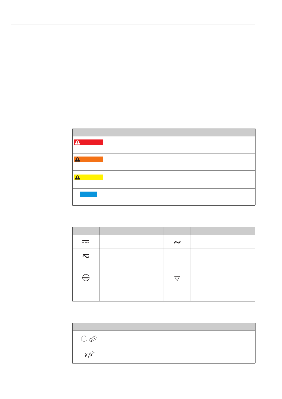
1.2.1 Safety symbols
Symbol Meaning
DANGER!
A0011189-DE
A0011190-DE
A0011191-DE
A0011192-DE
This symbol alerts you to a dangerous situation. Failure to avoid this situation will result in
seriousor fatal injury.
WARNING!
This symbol alerts you to a dangerous situation. Failure to avoid this situation can result in
seriousor fatal injury.
CAUTION!
This symbol alerts you to a dangerous situation. Failure to avoid this situation can result in
minoror medium injury.
NOTICE!
This symbol contains information on procedures and other facts which do not result in
personalinjury.
1.2.2 Electrical symbols
Symbol Meaning Symbol Meaning
Direct current Alternating current
Direct current and alternating current Ground connection
Protective ground connection
A terminal which must be connected
to ground prior to establishing any
other connections.
1.2.3 Tool symbols
Symbol Meaning
Allen key
A0011221
Hexagon wrench
A grounded terminal which, as far as
the operator is concerned, is grounded
via a grounding system.
Equipotential connection
A connection that has to be connected
to the plant grounding system: This
may be a potential equalization line or
a star grounding system depending on
national or company codes of practice.
A0011222
4 Endress+Hauser
Page 5
Deltapilot S FMB70 with 4...20 mA HART Document information
A
,…,
1.
2.
3.
,…,
1.
2.
3.
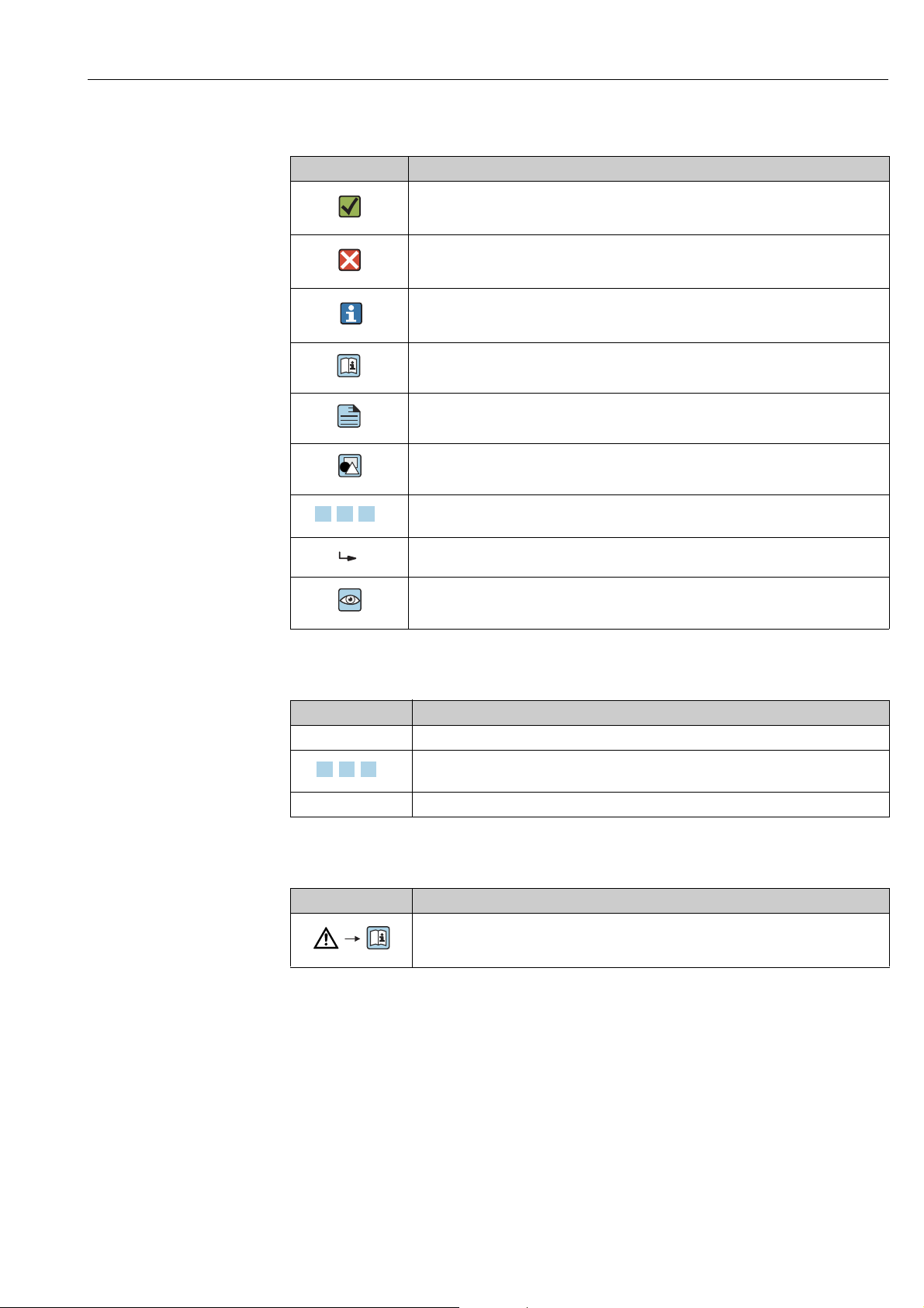
1.2.4 Symbols for certain types of information
Symbol Meaning
Permitted
Indicates procedures, processes or actions that are permitted.
A0011182
Forbidden
Indicates procedures, processes or actions that are forbidden.
A0011184
Tip
Indicates additional information.
A0011193
Reference to documentation
A0028658
Reference to page
A0028659
Reference to graphic
A0028660
Series of steps
A0031595
Result of a sequence of actions
A0018343
Visual inspection
A0028673
1.2.5 Symbols in graphics
Symbol Meaning
1, 2, 3, 4, ... Item numbers
Series of steps
A0031595
A, B, C, D, ... Views
1.2.6 Symbols at the device
Symbol Meaning
Safety instructions
Observe the safety instructions contained in the associated Operating Instructions.
A0019159
1.3 Registered trademarks
KALREZ, VITON, TEFLON
Registered trademarks of E.I. Du Pont de Nemours & Co., Wilmington, USA
TRI-CLAMP
Registered trademark of Ladish & Co., Inc., Kenosha, USA
HART
Registered trademark of the HART Communication Foundation, Austin, USA.
GORE-TEX
Registered trademarks of W.L. Gore & Associates, Inc., USA
®
Endress+Hauser 5
Page 6
Document information Deltapilot S FMB70 with 4...20 mA HART
URL OPLMWP
LRL
0
p
LRV
URV
1
2
3
4
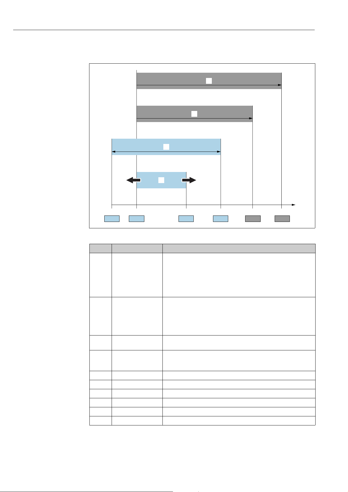
1.4 Terms and abbreviations
A0029505
Position Term/Abbreviation Explanation
1 OPL The OPL (over pressure limit = sensor overload limit) for the sensors
depends on the lowest-rated element, with regard to pressure, of the
selected components, i.e. the process connection must be taken into
consideration in addition to the measuring cell. Also observe pressuretemperature dependency. For the relevant standards and additional notes,
see technical information.
The OPL may be applied for a limited time period.
2 MWP The MWP (maximum working pressure) for the sensors depends on the
lowest-rated element, with regard to pressure, of the selected components,
i.e. the process connection has to be taken into consideration in addition to
the measuring cell. Also observe pressure-temperature dependency. For the
relevant standards and additional notes, see technical information.
The MWP may be applied for an unlimited time.
3Maximum sensor
measuring range
4 Calibrated/Adjusted
measuring span
p - Pressure
- LRL Lower range limit
-URL Upper range limit
- LRV Lower range value
-URV Upper range value
-TD Turn down
Range between LRL and URL
This span is the maximum calibratable/adjustable measuring span.
Range between LRV and URV
Factory setting: 0...URL
Other calibrated spans can be ordered with customised settings.
6 Endress+Hauser
Page 7

Deltapilot S FMB70 with 4...20 mA HART Document information
LRV
URLURV
LRL
1 = 2
3
1.5 Turn down calculation
A0029545
Fig. 1:
1 Calibrated/Adjusted measuring span
2 Zero-based span
3 Upper range limit
Example
• Sensor: 10 bar (150 psi)
• Upper range limit (URL) = 10 bar (150 psi)
Turn down (TD):
TD =
|URV - LRV|
URL
• Calibrated/Adjusted measuring span: 0...5 bar
(0...75 psi)
• Lower range value (LRV) = 0 bar
• Upper range value (URV) = 5 bar (75 psi)
TD =
In this example, the TD is thus 2:1.
This span is based on the zero point.
|5 bar (75 psi) - 0 bar (0 psi)|
10 bar (150 psi)
=2
Endress+Hauser 7
Page 8

Basic safety instructions Deltapilot S FMB70 with 4...20 mA HART
2 Basic safety instructions
2.1 Requirements concerning the staff
The personnel for installation, commissioning, diagnostics and maintenance must fulfill the
following requirements:
• Trained, qualified specialists: must have a relevant qualification for this specific function
and task
• Are authorized by the plant owner/operator
• Are familiar with federal/national regulations
• Before beginning work, the specialist staff must have read and understood the instructions
in the Operating Instructions and supplementary documentation as well as in the
certificates (depending on the application)
• Following instructions and basic conditions
The operating personnel must fulfill the following requirements:
• Being instructed and authorized according to the requirements of the task by the facility's
owner-operator
• Following the instructions in these Operating Instructions
2.2 Designated use
The Deltapilot S is a hydrostatic pressure transmitter for measuring level and pressure.
2.2.1 Incorrect use
The manufacturer is not liable for damage caused by improper or non-designated use.
Verification for borderline cases:
For special fluids and fluids for cleaning, Endress+Hauser is glad to provide assistance in
verifying the corrosion resistance of fluid-wetted materials, but does not accept any
warranty or liability.
2.3 Workplace safety
For work on and with the device:
• Wear the required personal protective equipment according to federal/national
regulations.
• Switch off the supply voltage before connecting the device.
2.4 Operational safety
Risk of injury!
‣ Operate the device in proper technical condition and fail-safe condition only.
‣ The operator is responsible for interference-free operation of the device.
Conversions to the device
Unauthorized modifications to the device are not permitted and can lead to unforeseeable
dangers:
‣ If, despite this, modifications are required, consult with Endress+Hauser.
Repair
To ensure continued operational safety and reliability,
‣ Carry out repairs on the device only if they are expressly permitted.
‣ Observe federal/national regulations pertaining to repair of an electrical device.
‣ Use original spare parts and accessories from Endress+Hauser only.
8 Endress+Hauser
Page 9

Deltapilot S FMB70 with 4...20 mA HART Basic safety instructions
2.5 Hazardous area
To eliminate a danger for persons or for the facility when the device is used in the hazardous
area (e.g. explosion protection, pressure vessel safety):
• Based on the nameplate, check whether the ordered device is permitted for the intended
use in the hazardous area.
• Observe the specifications in the separate supplementary documentation that is an
integral part of these Instructions.
2.6 Product safety
This measuring device is designed in accordance with good engineering practice to meet
state-of-the- art safety requirements, has been tested, and left the factory in a condition in
which they are safe to operate. It fulfills general safety requirements and legal requirements.
It also conforms to the EC directives listed in the device-specific EC declaration of conformity.
Endress+Hauser confirms this fact by applying the CE mark.
2.7 Functional Safety SIL3 (optional)
If using devices for applications with safety integrity, the Functional Safety Manual must be
observed thoroughly.
Endress+Hauser 9
Page 10
Identification Deltapilot S FMB70 with 4...20 mA HART
Ser. no.:
Order code:
Ext. order code:
2
5
6
3
4
1
3 Identification
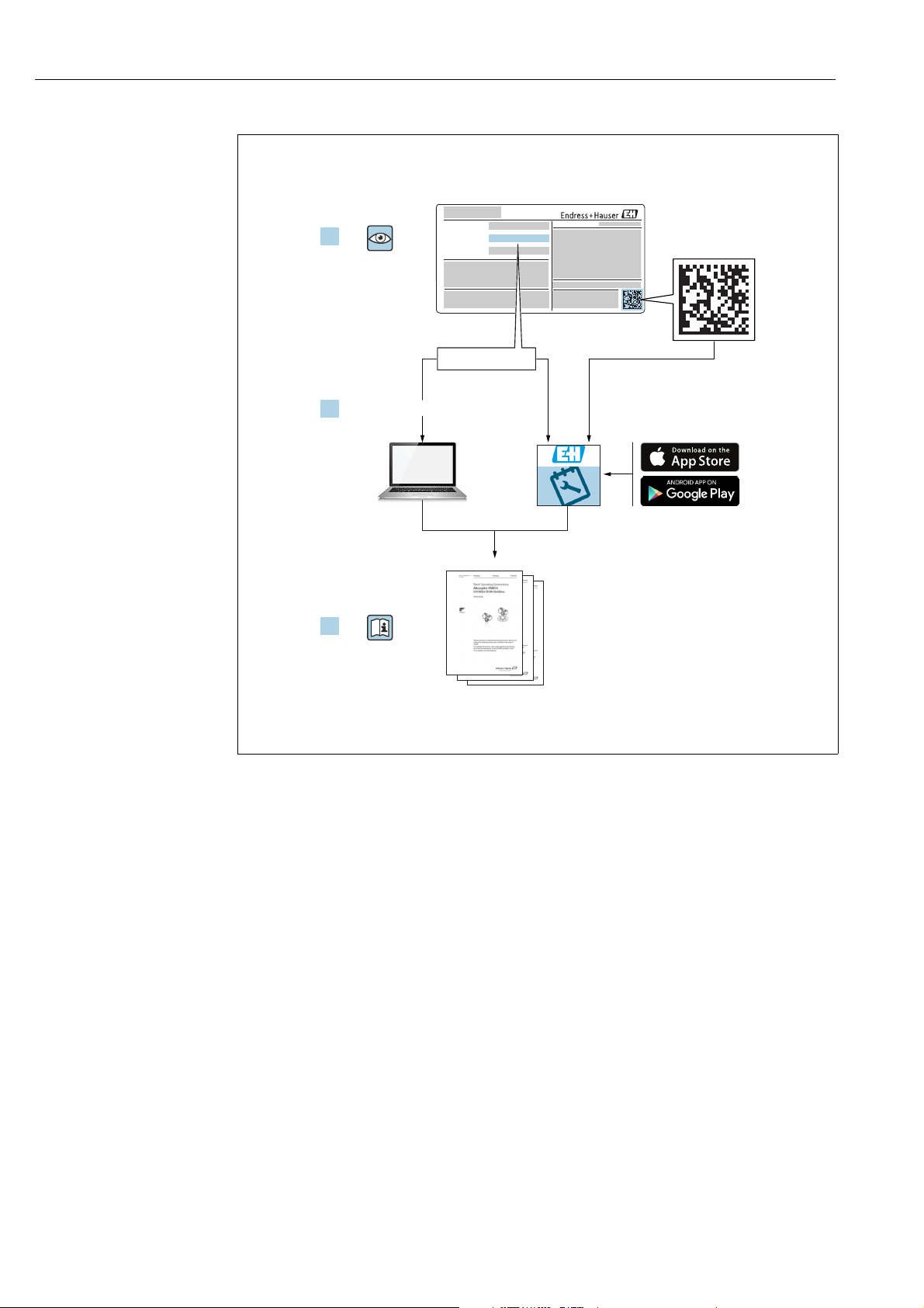
3.1 Product identification
The following options are available for identification of the measuring device:
• Nameplate specifications
• Order code with breakdown of the device features on the delivery note
• Enter serial numbers from nameplates in W@M Device Viewer
(www.endress.com/deviceviewer) : All information about the measuring device is
displayed.
For an overview of the technical documentation provided, enter the serial number from the
nameplates in the W@M Device Viewer (www.endress.com/deviceviewer).
3.1.1 Manufacturer address
Endress+Hauser GmbH+Co. KG
Hauptstraße 1
79689 Maulburg, Germany
Address of the manufacturing plant: See nameplate.
3.2 Device designation
3.2.1 Nameplate
• The MWP (maximum working pressure) is specified on the nameplate. This value refers
to a reference temperature of +20 °C (68°F) and may be applied to the device for an
unlimited time. Observe temperature dependency of the MWP. The pressure values
permitted at higher temperatures can be found in the standards EN 1092-1: 2001 Tab. 18
(With regard to their stability-temperature property, the materials 1.4435 and 1.4404 are
grouped together under 13EO in EN 1092-1 Tab. 18. The chemical composition of the two
materials can be identical.), ASME B 16.5a – 1998 Tab. 2-2.2 F316, ASME B 16.5a –
1998 Tab. 2.3.8 N10276, JIS B 2220.
• The test pressure corresponds to the over pressure limit (OPL) of the device = MWP x 1.5.
• The Pressure Equipment Directive (2014/68/EU) uses the abbreviation "PS".
The abbreviation "PS" corresponds to the MWP (maximum working pressure) of the
measuring device.
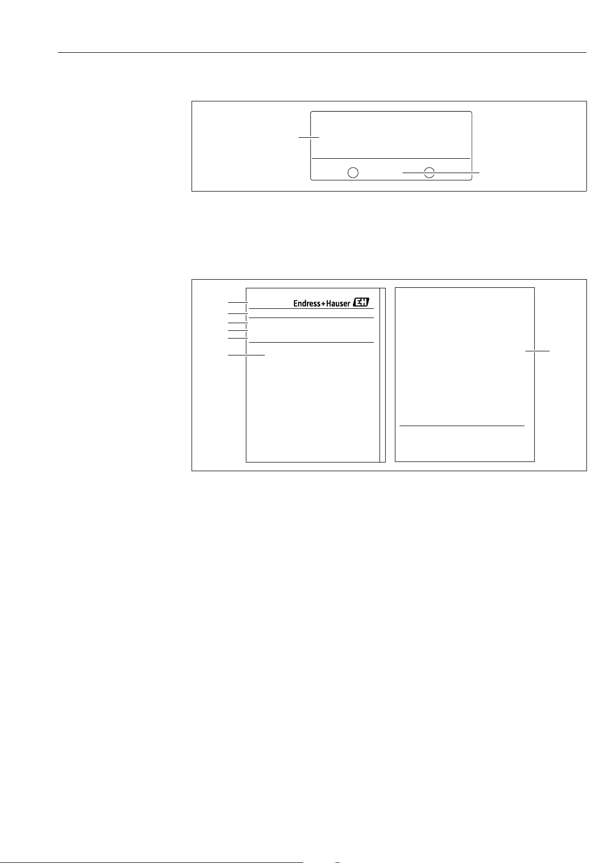
Aluminum housing (T14/T15)
Fig. 2: Nameplate
1Device name
2 Order code (for re-orders)
3 Extended order code (complete)
4Technical data
5 Serial number (for identification)
6 Address of manufacturer
10 Endress+Hauser
A0016056
Page 11
Deltapilot S FMB70 with 4...20 mA HART Identification
2
1
2
7
3
4
5
6
1
Ser. no.:
Order code:
Ext. ord. cd.:
Devices for use in hazardous areas are fitted with an additional nameplate.
A0021222
Fig. 3: Additional nameplate
1 Approval-specific information
2 Document number for safety instructions or drawing number
Hygenic stainless steel housing (T17)
A0021552
Fig. 4: Nameplate
1 Device name
2 Address of manufacturer
3 Order code (for re-orders)
4 Extended order code (complete)
5 Serial number (for identification)
6Technical data
7 Approval-specific information and document number for safety instructions or drawing number
3.2.2 Identifying the sensor type
See parameter "Sensor Meas.Type" in Operating Instruction BA00274P.
Endress+Hauser 11
Page 12

Identification Deltapilot S FMB70 with 4...20 mA HART
3.3 Scope of delivery
The scope of delivery comprises:
• Deltapilot S hydrostatic pressure transmitter
• For devices with the "HistoROM/M-DAT" option:
CD-ROMs with Endress+Hauser operating program
• Optional accessories
Documentation supplied:
• The Operating Instructions BA00332P and BA00274P are available via the Internet.
See: www.endress.com Download.
• Brief Operating Instructions KA01020P
• Leporello KA00218P
• Final inspection report
• Also Safety Instructions with devices for use in hazardous areas
• Optional: factory calibration form, test certificates
3.4 CE mark, declaration of conformity
The device is designed to meet state-of-the-art safety requirements, has been tested and left
the factory in a condition in which it is safe to operate. The device complies with the
applicable standards and regulations as listed in the EC declaration of conformity and thus
complies with the statutory requirements of the EC Directives. Endress+Hauser confirms the
successful testing of the device by affixing to it the CE mark.
12 Endress+Hauser
Page 13

Deltapilot S FMB70 with 4...20 mA HART Installation
WARNING
!
4Installation
4.1 Incoming acceptance and storage
4.1.1 Incoming acceptance
• Check the packaging and the contents for damage.
• Check the shipment, make sure nothing is missing and that the scope of supply matches
your order.
4.1.2 Transport
Incorrect transportation
Housing and diaphragm may become damaged, and there is a risk of injury!
‣ Transport the measuring device to the measuring point in its original packaging or by the
process connection (with secure transport protection for the diaphragm).
‣ Follow the safety instructions and transport conditions for devices weighing more than
18 kg (39.6 lbs).
4.1.3 Storage
The device must be stored in a dry, clean area and protected against damage from impact
(EN 837-2).
Storage temperature range:
• –40 to +90°C (–40 to +194°F)
• On-site display: –40 to +85°C (–40 to +185°F)
• Separate housing: –40 to +60°C (–40 to +140°F)
4.2 Installation conditions
4.2.1 Dimensions
For dimensions, please refer to the Technical Information for Deltapilot S TI00416P,
"Mechanical construction" section.
4.3 General installation instructions
• Devices with a G 1 1/2 thread:
When screwing the device into the tank, the flat seal has to be positioned on the sealing
surface
of the process connection. To avoid additional strain on the process isolating diaphragm,
the thread should never be sealed with hemp or similar materials.
• Devices with NPT threads:
– Wrap Teflon tape around the thread to seal it.
– Tighten the device at the hexagonal bolt only. Do not turn at the housing.
– Do not overtighten the thread when screwing. Max. torque: 20 to 30 Nm (14.75 to
22.13 lbf ft)
Endress+Hauser 13
Page 14
Installation Deltapilot S FMB70 with 4...20 mA HART
NOTICE
1
1
1
FIELDTERMINALS
FIELDTERMINALS
FIELDTERMINALSFIELDTERMINALS
F
IE
L
D
T
E
R
M
IN
A
L
S
FIELDTERMINALS
F
IE
L
D
T
E
R
M
IN
A
L
S
FIELDTERMINALS
F
IE
L
D
T
E
R
M
IN
A
L
S
FIELDTERMINALS
4.4 Installation instructions
• Due to the orientation of the Deltapilot S, there may be a shift in the measured value, i.e.
when the container is empty, the measured value does not display zero. You may correct
this zero point shift either directly on the device using the -key or by remote operation.
ä 27, "Function of the operating elements – on-site display not connected" or ä 40,
"Position adjustment"..
• To ensure optimal readability of the on-site display, it is possible to rotate the housing up
to 380°. ä 18, Section 4.4.5 "Rotating the housing".
• The on-site display can be rotated in 90° stages.
• Endress+Hauser offers a mounting bracket for installing on pipes or walls. ä 16,
Section 4.4.3 "Wall and pipe mounting (optional)".
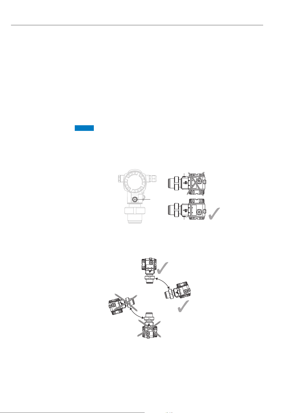
4.4.1 Installation instructions
Damage to the device!
If a heated Deltapilot S is cooled during the cleaning process (e.g. by cold water), a vacuum
develops for a short time, whereby moisture can penetrate the sensor through the pressure
compensation (1).
‣ If this is the case, mount the sensor with the pressure compensation (1) pointing
downwards.
®
• Keep the pressure compensation and GORE-TEX
filter (1) free from contaminations.
• Do not clean or touch process isolating diaphragm with hard or pointed objects.
• The device must be installed as follows in order to comply with the cleanability
requirements of the ASME-BPE (Part SD Cleanability):
14 Endress+Hauser
Page 15
Deltapilot S FMB70 with 4...20 mA HART Installation
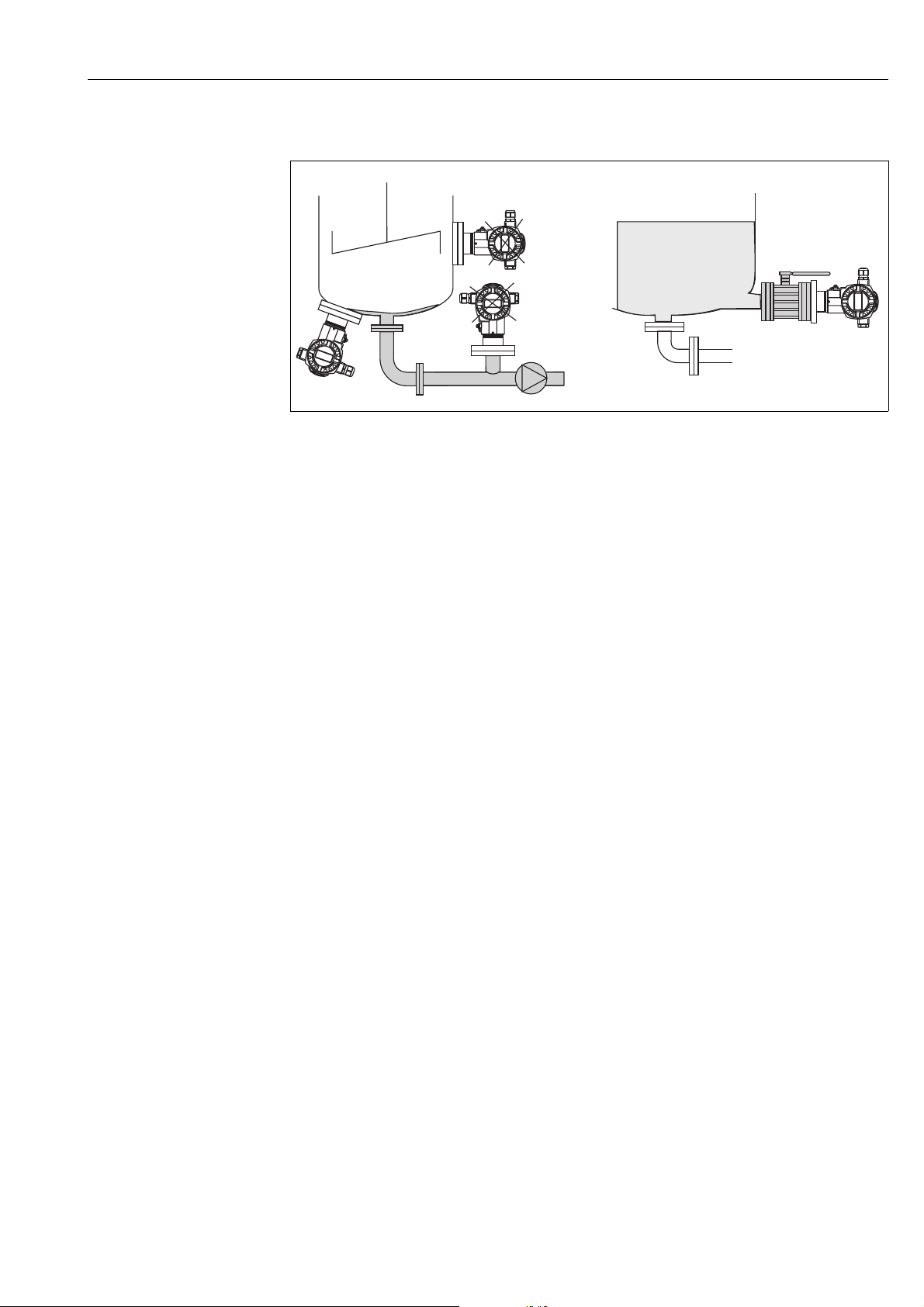
Level measurement
P01-PMP75xxx-11-xx-xx-xx-000
Fig. 5: Measuring arrangement for level
• Always install the device below the lowest measuring point.
• Do not install the device at the following positions:
– in the filling curtain
– in the tank outflow
– in the suction area of a pump
– or at a point in the tank that can be affected by pressure pulses from the agitator
• The calibration and functional test can be carried out more easily if you mount the device
downstream of a shutoff device.
• Deltapilot S must be included in the insulation for media that can harden when cold.
Pressure measurement in gases
• Mount Deltapilot S with shutoff device above the tapping point so that any condensate can
flow into the process.
Pressure measurement in steams
• Mount Deltapilot S with siphon above the tapping point.
• Fill the siphon with liquid before commissioning.
The siphon reduces the temperature to almost the ambient temperature.
Pressure measurement in liquids
• Mount Deltapilot S with the shutoff device below or at the same level as the tapping point.
Endress+Hauser 15
Page 16
Installation Deltapilot S FMB70 with 4...20 mA HART
NOTICE
12
122 (4.8)
52 (2.05)
86 (3.39)
70 (2.76)
140 (5.51)
158 (6.22)
175 (6.89)
ø6 (0.24)
ø42...60 (1.65...2.36)
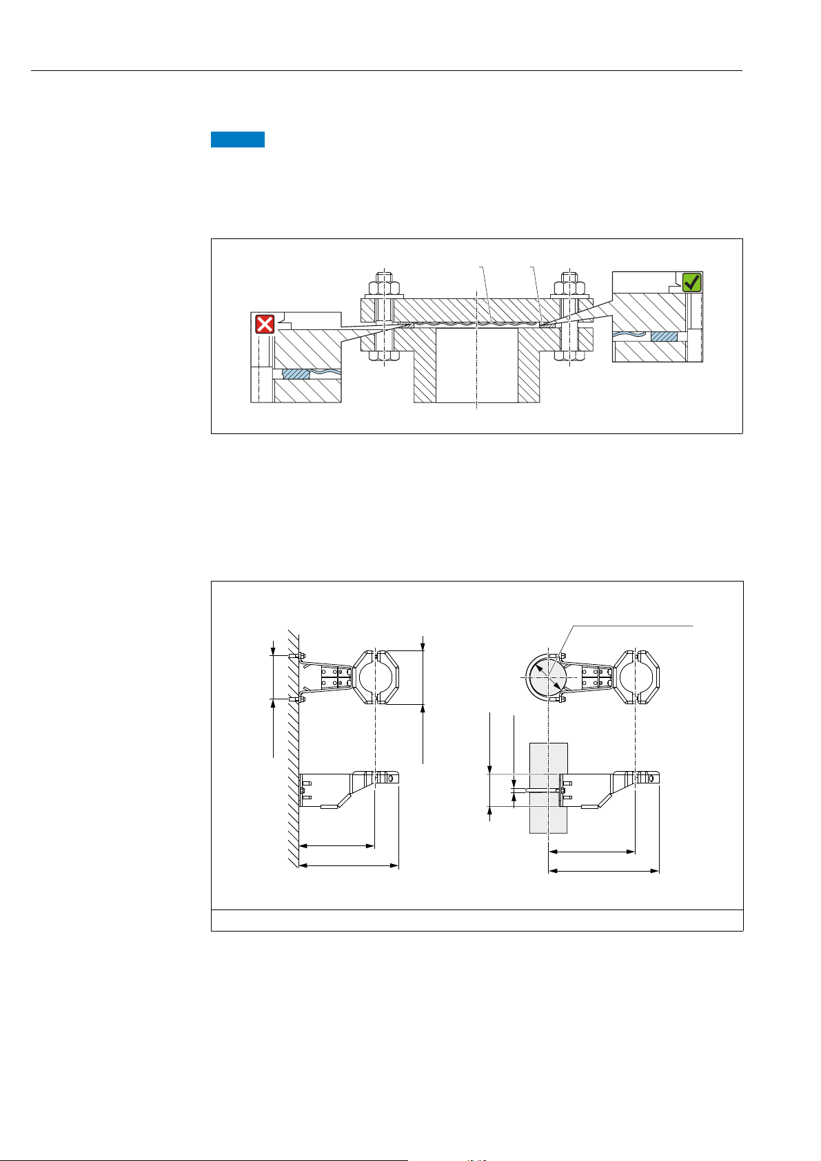
4.4.2 Seal for flange mounting
Corrupted measurement results.
The seal is not allowed to press against the process isolating diaphragm as this could affect
the measurement result.
‣ Ensure that the seal is not touching the process isolating diaphragm.
A0017743
Fig. 6:
1 Process isolating diaphragm
2Seal
4.4.3 Wall and pipe mounting (optional)
Endress+Hauser offers a mounting bracket for installation on pipes or walls (for pipe
diameters from 1 ¼" to 2").
Engineering unit mm (in)
A0028493
Please note the following when mounting:
• Devices with capillary tubes: mount capillaries with a bending radius 100 mm (3.94 in).
• When mounting on a pipe, tighten the nuts on the bracket uniformly with a torque of at
least 5 Nm (3.69 lbs ft).
16 Endress+Hauser
Page 17
Deltapilot S FMB70 with 4...20 mA HART Installation
r ³ 120 mm
1
2
3
5
6
8
7
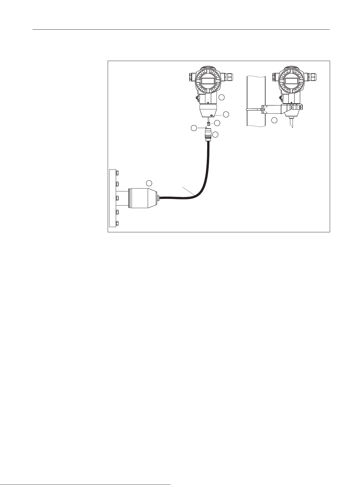
4.4.4 Assembling and mounting the "separate housing" version
P01-FMB70xxx-11-xx-xx-xx-003
Fig. 7: "Separate housing" version
1 In the "separate housing" version, the sensor is supplied with process connection and cable fitted.
2 Cable with connection jack
3 Pressure compensation
5Plug
6Locking screw
7 Housing fitted with housing adapter, included
8 Mounting bracket suitable for wall and pipe mounting, included
Assembly and mounting
1. Connect plug (item 5) into the corresponding connection jack of the cable (item 2).
2. Plug the cable into the housing adapter (item 7).
3. Tighten the locking screw (item 5).
4. Mount the housing on a wall or pipe using the mounting bracket (item 8). When
mounting on a pipe, tighten the nuts on the bracket uniformly with a torque of at least
5 Nm (3.69 lbs ft).
Mount the cable with a bending radius (r) 120 mm (4.72 in).
Endress+Hauser 17
Page 18
Installation Deltapilot S FMB70 with 4...20 mA HART
NOTICE
NOTICE
T14
T15
T17
32
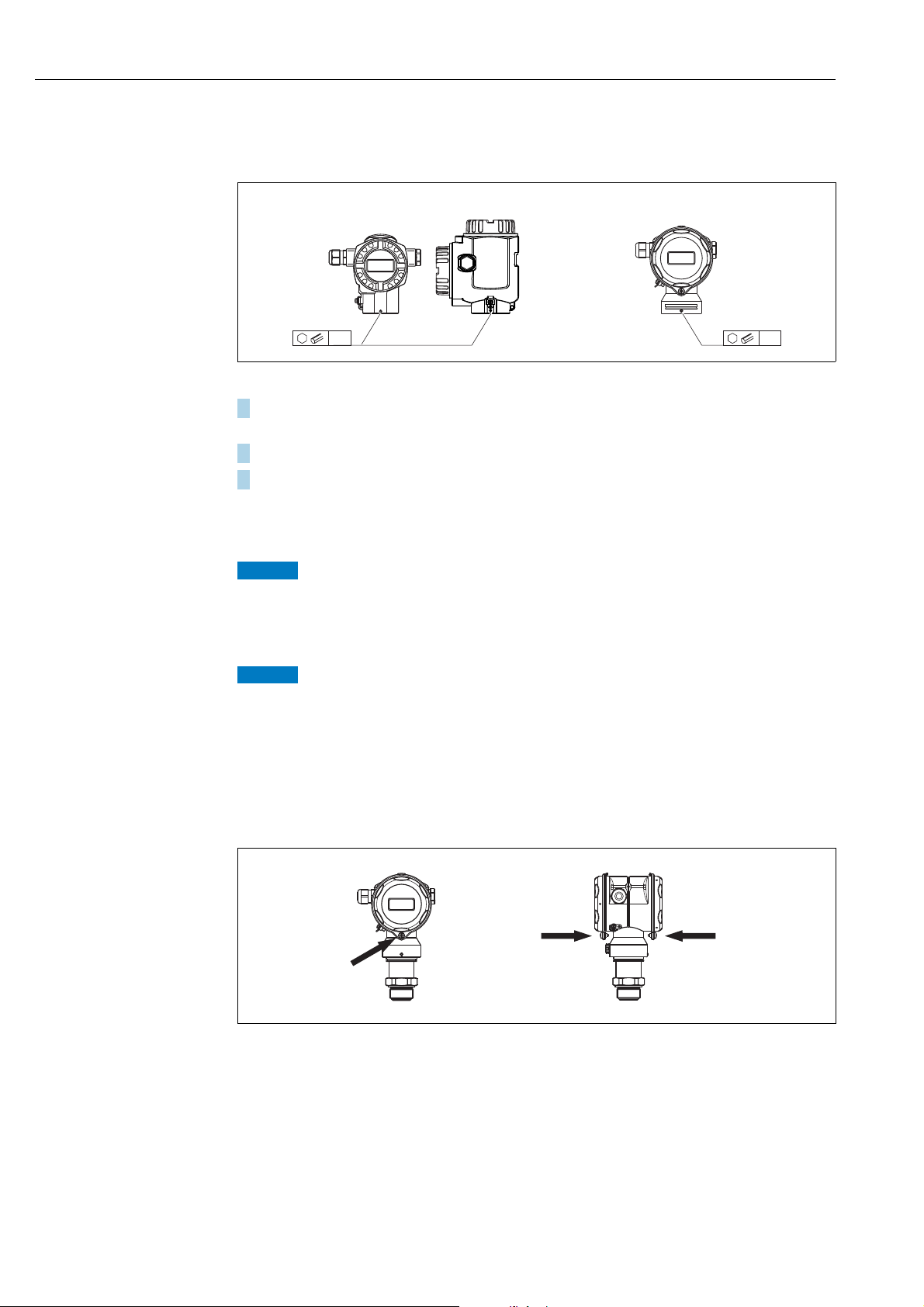
4.4.5 Rotating the housing
The housing can be rotated up to 380° by loosening the Allen screw.
A0019996
1. T14 and T15 housing: Loosen setscrew with a 2 mm (0.08 in) Allen key.
T17 housing: Loosen setscrew with a 3 mm (0.12 in) Allen key.
2. Rotate housing (max. up to 380 °).
3. Retighten setscrew with 1 Nm (0,74 lbf ft.
4.4.6 Closing the housing cover
Devices with EPDM cover seal - transmitter leakiness!
Mineral-based, animal-based or vegetable-based lubricants cause the EPDM cover seal to
swell and the transmitter to become leaky.
‣ The thread is coated at the factory and therefore does not require any lubrication.
The housing cover can no longer be closed.
Damaged thread!
‣ When closing the housing cover, please ensure that the thread of the cover and housing
are free from dirt, e.g. sand.If you feel any resistance when closing the cover, check the
thread on both again to ensure that they are free from dirt.
Close cover on a hygenic stainless steel housing (T17)
P01-FMB70xxx-17-xx-xx-xx-001
Fig. 8: Close cover
The covers for the terminal and electronics compartment are hooked into the casing and
closed with a screw. These screws should be finger-tightened (2 Nm (1.48 lbf ft)) to the stop
to ensure that the covers sit tightly.
18 Endress+Hauser
Page 19

Deltapilot S FMB70 with 4...20 mA HART Installation
4.4.7 Mounting of the profile seal for universal process mounting
adapter
For details on mounting, see KA00096F/00/A3.
4.5 Post-installation check
After installing the device, carry out the following checks:
• Are all screws firmly tightened?
• Are the housing covers screwed down tight?
Endress+Hauser 19
Page 20
Wiring Deltapilot S FMB70 with 4...20 mA HART
WARNING
!
WARNING
!
4…20 mA
➅
10.5 V DC
➆
11.5 V DC
4... 20mA
Test
Test
➀
➁
➂
➃
➄
Test
➇
4... 20mATest
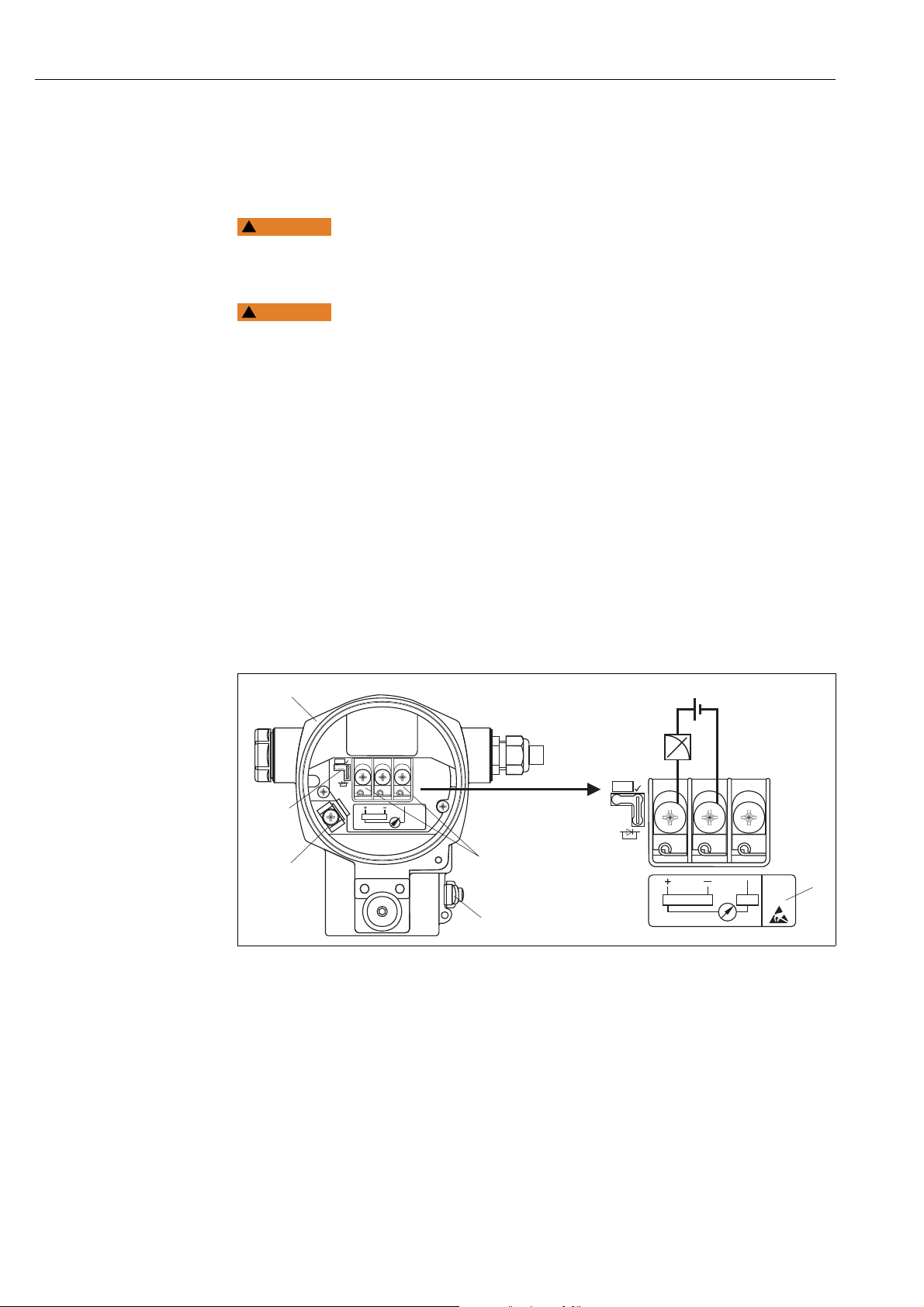
5 Wiring
5.1 Connecting the device
Risk of electric shock!
If the operating voltage is > 35 VDC: Dangerous contact voltage at terminals.
‣ In a wet environment, do not open the cover if voltage is present.
Limitation of electrical safety due to incorrect connection!
• Risk of electric shock and/or explosion in hazardous areas! In a wet environment, do not
open the cover if voltage is present.
• When using the measuring device in hazardous areas, installation must comply with the
corresponding national standards and regulations and the Safety Instructions or
Installation or Control Drawings.
• Devices with integrated overvoltage protection must be earthed.
• Protective circuits against reverse polarity, HF influences and overvoltage peaks are
installed.
• The supply voltage must match the supply voltage on the nameplate. ( ä 10,
Section 3.2.1 "Nameplate")
• Switch off the supply voltage before connecting the device.
• Remove housing cover of the terminal compartment.
• Guide cable through the gland. Preferably use twisted, screened two-wire cable.
• Connect device in accordance with the following diagram.
• Screw down housing cover.
• Switch on supply voltage.
P01-xMx7xxxx-04-xx-xx-xx-001
Fig. 9: Electrical connection 4 to 20 mA HART
1Housing
2 Jumper for 4 to 20 mA test signal.
3 Internal earth terminal
4 External earth terminal
5 4 to 20 mA test signal between plus and test terminal
6 Minimum supply voltage = 10.5 V DC, jumper is inserted in accordance with the illustration.
7 Minimum supply voltage = 11.5 V DC, jumper is inserted in "Test" position.
8 Devices with integrated overvoltage protection are labelled OVP (overvoltage protection) here.
20 Endress+Hauser
Observe also Section 5.2.1 "Supply voltage",
ä
22, Section 5.2.1 "Taking 4 to 20 mA test signal" part.
ä
22.
Page 21

Deltapilot S FMB70 with 4...20 mA HART Wiring
Han7D
–
+
+–
–
+
1
5
4
6
7
8
2
3
AB
2
1
34
–
+
+
PE
–
rd
bk
gnye
4...20 mA
5.1.1 Connecting devices with Harting plug Han7D
A0019990
Fig. 10:
A Electrical connection for devices with Harting plug Han7D
B View of the plug connector at the device
5.1.2 Connecting devices with an M12 connector
PIN assignment for M12 connector PIN Meaning
1Signal +
2Not assigned
3Signal –
4Earth
A0011175
5.1.3 Connecting the cable version
Fig. 11: rd = red, bk = black, gnye = green-yellow
P01-PMx4xxxx-04-xx-xx-xx-010
Endress+Hauser 21
Page 22

Wiring Deltapilot S FMB70 with 4...20 mA HART
WARNING
!
Test
TestTest
5.2 Connecting the measuring unit
5.2.1 Supply voltage
Supply voltage might be connected!
Risk of electric shock and/or explosion!
‣ When using the measuring device in hazardous areas, installation must comply with the
corresponding national standards and regulations and the Safety Instructions or
Installation or Control Drawings.
‣ All explosion protection data are given in separate documentation which is available
upon request. The Ex documentation is supplied as standard with all devices approved for
use in explosion hazardous areas.
Electronic version Jumper for 4 to 20 mA test signal
4 to 20 mA HART, for nonhazardous areas
in "Test" position (Delivery status)
11.5 to 45 V DC 10.5 to 45 V DC
Jumper for 4 to 20 mA test signal
in "Non-Test" position
Taking 4 to 20 mA test signal
A 4 to 20 mA signal may be measured via the positive and test terminal without interrupting
the measurement. The minimum supply voltage of the device can be reduced by simply
changing the position of the jumper. As a result, operation is also possible with lower voltage
sources. To keep the measured error below 0.1%, the current measuring device should
display an internal resistance of < 0.7 . Observe the position of the jumper in accordance
with the following table.
Jumper position for test signal Description
– Taking 4 to 20 mA test signal via plus and test terminal:
possible. (Thus, the output current can be measured without
interruption via the diode.)
–Delivery status
– minimum supply voltage: 11.5 V DC
– Taking 4 to 20 mA test signal via plus and test terminal:
not possible.
– minimum supply voltage: 10.5 V DC
5.2.2 Terminals
• Supply voltage and internal ground terminal: 0.5 to 2.5 mm2 (20 to 14 AWG)
• External ground terminal: 0.5 to 4 mm
2
(20 to 12 AWG)
5.2.3 Cable specification
• Endress+Hauser recommends using twisted, screened two-wire cables.
• Cable external diameter: 5 to 9 mm (0.2 to 0.35 in)
22 Endress+Hauser
Page 23

Deltapilot S FMB70 with 4...20 mA HART Wiring
U – 10.5 V
R
L
max
23 mA
≤
30
20
10.5
U
[V]
40 45
1282
1500
847
413
[]Ω
R
L
max
30
20
11.5
U
[V]
40 45
1239
1456
804
369
[]Ω
R
L
max
TestTest
➀
➁
U – 11.5 V
R
L
max
23 mA
≤
➂
➃
➂
➃
5.2.4 Load
P01-xMD7xxxx-05-xx-xx-xx-005
Fig. 12: Load diagram, observe the position of the jumper and the explosion protection. (
1 Jumper for the 4 to 20 mA test signal inserted in "Non-Test" position
2 Jumper for the 4 to 20 mA test signal inserted in "Test" position
3 Supply voltage 10.5 (11.5) to 30 V DC for Ex ia, 1/2 D, 1 GD, 1/2 GD, FM IS and CSA IS, IEC Ex ia, NEPSI Ex ia
4 Supply voltage10.5 (11.5) to 45 V DC for devices for non-hazardous areas, 1/3 D, Ex nA, FM DIP, FM NI
R
Lmax
U Supply voltage
mA test signal" part.)
Maximum load resistance
ä
22, Section 5.2.1 "Taking 4 to 20
When operating via a handheld terminal or via PC with an operating program, a minimum
communication resistance of 250 must exist within the loop.
5.2.5 Screening/potential matching
• You achieve optimum screening against disturbances if the screening is connected on both
sides (in the cabinet and on the device). If you have to reckon with potential equalisation
currents in the plant, only earth screening on one side, preferably at the transmitter
(possibility of hydrogen diffusion).
• When using in hazardous areas, you must observe the applicable regulations.
Separate Ex documentation with additional technical data and instructions is included
with all Ex systems as standard.
5.2.6 Connecting Field Xpert SFX100
Compact, flexible and robust industry handheld terminal for remote parametrization and
measured value inspection via the HART current output (4-20mA).
For details refer to Operating Instructions BA00060S/04/EN.
5.2.7 Connecting Commubox FXA195
The Commubox FXA195 connects intrinsically safe transmitters with the HART protocol to
a computer's USB port. This allows remote operation of the transmitter using
Endress+Hauser's FieldCare operating program. Power is supplied to the Commubox
through the USB port. The Commubox is also suitable for connection to intrinsically safe
circuits. See Technical Information TI00404F for further information.
Endress+Hauser 23
Page 24

Wiring Deltapilot S FMB70 with 4...20 mA HART
NOTICE
5.2.8 Connecting Commubox FXA291/ToF Adapter FXA291 for
operation via FieldCare
Connecting Commubox FXA291
The Commubox FXA291 connects Endress+Hauser field instruments with CDI interface (=
Endress+Hauser Common Data Interface) to the USB interface of a personal computer or a
notebook. For details refer to TI00405C/07/en.
For the following Endress+Hauser instruments you need the "ToF Adapter FXA291" as an
additional accessory:
• Cerabar S PMC71, PMP7x
• Deltabar S PMD7x, FMD7x
• Deltapilot S FMB70
Connecting ToF Adapter FXA291
The ToF Adapter FXA291 connects the Commubox FXA291 via the USB interface of a
personal computer or a notebook to the following Endress+Hauser instruments:
• Cerabar S PMC71, PMP7x
• Deltabar S PMD7x, FMD7x
• Deltapilot S FMB70
For details refer to KA00271F/00/a2.
5.3 Potential matching
Ex applications: Connect all devices to the local potential matching.
Observe the applicable regulations.
5.4 Overvoltage protection (optional)
Device could be destroyed!
Devices with integrated overvoltage protection must be earthed.
Devices showing version "M" in feature 100 "Additional options 1" or feature 110 "Additional
options 2" in the order code are equipped with overvoltage protection (see also Technical
Information TI00416P "Ordering information".
• Overvoltage protection:
– Nominal functioning DC voltage: 600 V
– Nominal discharge current: 10 kA
• Surge current check î = 20 kA as per DIN EN 60079-14: 8/20 s satisfied
• Arrester AC current check I = 10 A satisfied
5.5 Post-connection check
Perform the following checks after completing electrical installation of the device:
• Does the supply voltage match the specifications on the nameplate?
• Is the device connected as per Section 5.1?
• Are all screws firmly tightened?
• Are the housing covers screwed down tight?
As soon as voltage is applied to the device, the green LED on the electronic insert lights up
for a few seconds or the connected on-site display lights up.
24 Endress+Hauser
Page 25

Deltapilot S FMB70 with 4...20 mA HART Operation
E
+
–
Bargraph
Operating keys
Symbol
Bargraph
ValueFunction name
Measured value display
Unit
Header line
Information
line
Main line
Parameter
Identification
number
Editing modes
Selection
options
Value that
can be ed
ited
Current measured value
6Operation
Feature 20 "Output; operation" in the order code provides you with information on the
operating options available to you.
6.1 On-site display (optional)
A 4-line liquid crystal display (LCD) is used for display and operation. The on-site display
shows measured values, dialog texts, fault messages and notice messages.
The display of the device can be turned in 90° steps.
Depending on the installation position of the device, this makes it easy to operate the device
and read the measured values.
Functions:
• 8-digit measured value display including sign and decimal point, bargraph for current
display
• simple and complete menu guidance thanks to separation of the parameters into several
levels and groups
• each parameter is given a 3-digit ID number for easy navigation
• option for configuring the display according to individual requirements and desires, such
as language, alternating display, contrast setting, display of other measured values such
as sensor temperature
• comprehensive diagnostic functions (fault and warning message, peak-hold indicators,
etc.)
• rapid and safe commissioning with the Quick Setup menus
Endress+Hauser 25
P01-xMx7xxxx-07-xx-xx-xx-001
Page 26

Operation Deltapilot S FMB70 with 4...20 mA HART
➀
➂
➀
➁
➃
21
PC
t
on
off
➅
➄
The following table illustrates the symbols that can appear on the on-site display. Four
symbols can occur at one time.
Symbol Meaning
Alarm symbol
– Symbol flashing: warning, device continues measuring.
– Symbol permanently lit: error, device does not continue measuring.
Note: The alarm symbol may overlie the tendency symbol.
Lock symbol
The operation of the device is locked. Unlock device, ä 36.
Communication symbol
Data transfer via communication
Note: The alarm symbol may overlie the communication symbol.
Tendency symbol (increasing)
The measured value is increasing.
Tendency symbol (decreasing)
The measured value is decreasing.
Tendency symbol (constant)
The measured value has remained constant over the past few minutes.
6.2 Operating elements
6.2.1 Position of operating elements
With regard to aluminium housings (T14/T15), the operating keys are located either
outside the device under the protection cap or inside on the electronic insert. In hygenic
stainless steel housings (T17), the operating keys are always located inside on the electronic
insert.
Fig. 13: Operating keys, external
1 Operating keys on the exterior of the device under the
protective flap
P01-PMx7xxxx-19-xx-xx-xx-009
P01-xxxxxxxx-19-xx-xx-xx-104
Fig. 14: Operating keys, internal
1 Operating keys
2 Slot for optional display
3 Slot for optional HistoROM
4 DIP-switch for locking/unlocking measured-value-
relevant parameters
5 DIP-switch for damping on/off
6 Green LED to indicate value being accepted
®
/M-DAT
26 Endress+Hauser
Page 27

Deltapilot S FMB70 with 4...20 mA HART Operation
1
2
τ
on
off
6.2.2 Function of the operating elements –
on-site display not connected
Press and hold the key or the key combination for at least 3 seconds to execute the
corresponding function. Press the key combination for at least 6 seconds for a reset.
Operating key(s) Meaning
Adopt lower range value. A reference pressure is present at the device.
ä 28, Section 6.3.1 "Level measuring mode" or ä 30, Section 6.3.2 "Level
measuring mode".
Adopt upper range value. A reference pressure is present at the device.
ä 28, Section 6.3.1 "Level measuring mode" or ä 30, Section 6.3.2 "Level
measuring mode".
Position adjustment
Reset all parameters. The reset via operating keys corresponds to the software reset
and and
code 7864.
Copy the configuration data from the optional HistoROM
and
and
P01-xxxxxxxx-19-xx-xx-xx-057
device.
Copy the configuration data from the device to the optional HistoROM
module.
– DIP-switch 1: for locking/unlocking measured-value-relevant parameters
Factory setting: off (unlocked)
– DIP-switch 2: damping on/off,
Factory setting: on (damping on)
6.2.3 Function of the operating elements –
on-site display connected
Operating key(s) Meaning
– Navigate upwards in the picklist
– Edit the numerical values and characters within a function
– Navigate downwards in the picklist
– Edit the numerical values and characters within a function
–Confirm entry
–Jump to the next item
Contrast setting of on-site display: darker
O
O
S
F
and
F
®
/M-DAT module to the
®
/M-DAT
Contrast setting of on-site display: brighter
and
S
O
Endress+Hauser 27
and
F
S
ESC functions:
– Exit edit mode without saving the changed value.
– You are in a menu within a function group. The first time you press the keys
simultaneously, you go back a parameter within the function group. Each time you
press the keys simultaneously after that, you go up a level in the menu.
– You are in a menu at a selection level. Each time you press the keys
simultaneously, you go up a level in the menu.
Note: The terms function group, level and selection level are explained in ä 31,
Section 6.4.1.
Page 28

Operation Deltapilot S FMB70 with 4...20 mA HART
WARNING
!
6.3 On-site operation – on-site display not connected
To operate the device with a HistoROM®/M-DAT module ä 33, Section 6.5 "HistoROM®/
M-DAT (optional)".
6.3.1 Level measuring mode
If no on-site display is connected, the following functions are possible by means of the three
keys on the electronic insert or on the exterior of the device:
• Position adjustment (zero point correction)
• Assign the lower and upper pressure value to the lower and upper level value
• Device reset, ä 27, Section 6.2.2 "Function of the operating elements – on-site display
not connected", Table.
•The "-" and - keys only have a function in the following cases:
– LEVEL SELECTION "Level Easy Pressure", CALIBRATION MODE "Wet"
– LEVEL SELECTION "Level Standard", LEVEL MODE "Linear",
CALIBRATION MODE "Wet"
The keys have no function in other settings.
• The device is configured for the Level measuring mode as standard. You can switch
measuring modes by means of the MEASURING MODE parameter. ä 39, Section 7.3
"Selecting language and measuring mode".
The following parameters are set to the following values in the factory:
– LEVEL SELECTION: Level Easy Pressure
–CALIBRATION MODE: Wet
– OUTPUT UNIT or LIN. MEASURAND: %
– EMPTY CALIB.: 0.0
– FULL CALIB.: 100.0.
– SET LRV: 0.0 (corresponds to 4 mA value)
– SET URV: 100.0 (corresponds to 20 mA value)
These parameters can only be modified by means of the on-site display or remote
operation such as the FieldCare.
• The operation must be unlocked. ä 36, Section 6.8 "Locking/unlocking operation".
• The pressure applied must be within the nominal pressure limits of the sensor. See
information on the nameplate.
• ä 42, Section 7.5 "Section 7.5". For parameter description see Operating Instructions
BA00274P.
• LEVEL SELECTION, CALIBRATION MODE, LEVEL MODE, EMPTY CALIB., FULL CALIB,
SET LRV and SET URV are parameter names used for on-site display or remote operation
such as FieldCare, for instance.
Changing the measuring mode can affect the adjustment data!
This situation can result in product overflow.
‣ Check calibration data when the measuring mode is changed.
28 Endress+Hauser
Page 29

Deltapilot S FMB70 with 4...20 mA HART Operation
Carry out position adjustment.
Pressure is present at device. Desired pressure for lower
1)
Setting lower pressure value. Setting upper pressure value.
Desired pressure for upper
pressure value (EMPTY
PRESSURE
2)
) is present at device.
pressure value (FULL PRESSURE
is present at device.
Press -key for 3 s. Press -key for 3 s. Press -key for 3 s.
Does the LED on the electronic
insert light up briefly?
Does the LED on the electronic
insert light up briefly?
Does the LED on the electronic
insert light up briefly?
Yes No Yes No Yes No
Applied
pressure for
position
adjustment has
been accepted.
Applied
pressure for
position
adjustment has
not been
accepted.
Observe the
input limits.
The pressure
present was
saved as the
lower pressure
value (EMPTY
PRESSURE
2
)
and assigned to
the lower level
value (EMPTY
2
CALIB.
).
The pressure
present was not
saved as the
lower pressure
value. Observe
the input limits.
The pressure
present was
saved as the
upper pressure
value (FULL
PRESSURE
2
)
and assigned to
the upper level
value (FULL
2
CALIB.
).
The pressure
present was not
saved as the
upper pressure
value. Observe
the input limits.
1) Observe "Warning" on ä 39, Section 7 "Commissioning".
2) Parameter name used for the on-site display or remote operation such as the FieldCare.
1
)
Endress+Hauser 29
Page 30

Operation Deltapilot S FMB70 with 4...20 mA HART
WARNING
!
6.3.2 Pressure measuring mode
If no on-site display is connected, the following functions are possible by means of the three
keys on the electronic insert or on the exterior of the device:
• Position adjustment (zero point correction)
• Setting lower range value and upper range value
• Device reset, ä 27, Section 6.2.2 "Function of the operating elements – on-site display
not connected", Table.
• The operation must be unlocked. ä 36, Section 6.8 "Locking/unlocking operation".
• The device is configured for the Level measuring mode as standard. You can switch
measuring modes by means of the MEASURING MODE parameter. ä 39, Section 7.3
"Selecting language and measuring mode".
• The pressure applied must be within the nominal pressure limits of the sensor. See
information on the nameplate.
Changing the measuring mode can affect the adjustment data!
This situation can result in product overflow.
‣ Check calibration data when the measuring mode is changed.
Carry out position adjustment.
Pressure is present at device. Desired pressure for lower range
Press -key for 3 s. Press -key for 3 s. Press -key for 3 s.
Does the LED on the electronic
insert light up briefly?
YesNo YesNo YesNo
Applied
pressure for
position
adjustment has
been accepted.
1) Observe "Warning" on ä 39, Section 7 "Commissioning".
Applied
pressure for
position
adjustment has
not been
accepted.
Observe the
input limits.
1)
Setting lower range value. Setting upper range value.
value is present at device.
Does the LED on the electronic
insert light up briefly?
Applied
pressure for
lower range
value has been
accepted.
Applied
pressure for
lower range
value has not
been accepted.
Observe the
input limits.
Desired pressure for upper range
value is present at device.
Does the LED on the electronic
insert light up briefly?
Applied
pressure for
upper range
value has been
accepted.
Applied
pressure for
upper range
value has not
been accepted.
Observe the
input limits.
30 Endress+Hauser
Page 31

Deltapilot S FMB70 with 4...20 mA HART Operation
6.4 On-site operation – on-site display connected
If the on-site display is connected, the three operating keys are used to navigate through the
operating menu and parameter input, ä 27, Section 6.2.3 "Function of the operating
elements – on-site display connected".
6.4.1 General structure of the operating menu
The menu is split into four levels. The three upper levels are used to navigate while you use
the bottom level to enter numerical values, select options and save settings.
The entire operating menu is shown in the operating instructions BA00274P "Cerabar S/
Deltabar S/Deltapilot S, Description of Instrument Functions".
The structure of the OPERATING MENU depends on the measuring mode selected, e.g. if the
"Pressure" measuring mode is selected, only the functions necessary for this mode are
displayed.
6.4.2 Selecting an option
Example: select "English" as the language of the menu.
On-site display Operation
German is selected as the language. A in front of the
menu text indicates the active option.
P01-xxxxxxxx-19-xx-xx-xx-017
Select English with or .
P01-xxxxxxxx-19-xx-xx-xx-033
1. Confirm your choice with . A in front of the
menu text indicates the active option. (English is
now selected as the menu language.)
2. Jump to the next item with .
P01-xxxxxxxx-19-xx-xx-xx-034
Endress+Hauser 31
Page 32

Operation Deltapilot S FMB70 with 4...20 mA HART
6.4.3 Editing a value
Example: adjusting DAMPING VALUE function from 2.0 s to 30.0 s. ä 27, Section 6.2.3
"Function of the operating elements – on-site display connected".
On-site display Operation
The on-site display shows the parameter to be
changed. The value highlighted in black can be
changed. The "s" unit is fixed and cannot be changed.
P01-xxxxxxxx-19-xx-xx-xx-023
1. Press or to get to the editing mode.
2. The first digit is highlighted in black.
P01-xxxxxxxx-19-xx-xx-xx-027
1. Use to change "2" to "3".
2. Confirm "3" with . The cursor jumps to the next
position (highlighted in black).
P01-xxxxxxxx-19-xx-xx-xx-028
P01-xxxxxxxx-19-xx-xx-xx-029
P01-xxxxxxxx-19-xx-xx-xx-030
P01-xxxxxxxx-19-xx-xx-xx-031
P01-xxxxxxxx-19-xx-xx-xx-032
The decimal point is highlighted in black, i.e. you can
now edit it.
1. Keep pressing or until "0" is displayed.
2. Confirm "0" with .
The cursor jumps to the next position. is
displayed and is highlighted in black. See next
graphic.
Use to save the new value and exit the editing mode.
See next graphic.
The new value for the damping is now 30.0 s.
– Jump to the next parameter with .
– You can get back to the editing mode with or
.
32 Endress+Hauser
Page 33

Deltapilot S FMB70 with 4...20 mA HART Operation
NOTICE
6.4.4 Taking pressure applied at device as value
Example: configuring upper range value – assign 20 mA to the pressure value 400 mbar.
On-site display Operation
The bottom line on the on-site display displays the
pressure present, here 400 mbar.
P01-xxxxxxxx-19-xx-xx-xx-035
Use or to switch to the "Confirm" option. The
active selection is highlighted in black.
P01-xxxxxxxx-19-xx-xx-xx-036
Use to assign the value (400 mbar) to the GET URV
parameter. The device confirms the calibration and
jumps back to the parameter, here GET URV (see next
graphic).
P01-xxxxxxxx-19-xx-xx-xx-037
Switch to the next parameter with .
P01-xxxxxxxx-19-xx-xx-xx-035
6.5 HistoROM®/M-DAT (optional)
Device could be destroyed!
Detach HistoROM
deenergised state only.
HistoROM
®
fulfils the following functions:
• Back-up copy of configuration data
• Copying configuration data of a transmitter into another transmitter
• Cyclic recording of pressure and sensor-temperature measured values
• Recording diverse events, such as alarms, configuration changes, counters for measuring
range undershooting and exceeding for pressure and temperature, exceeding and
undershooting the user limits for pressure and temperature, etc.
•The HistoROM
• The HistoROM data and the data in the device are analysed once a HistoROM
attached to the electronic insert and power is reestablished to the device. During the
analysis, the messages "W702, HistoROM data not consistent" and "W706, Configuration
in HistoROM and device not identical" can occur. For measures, ä 48, Section 9.1
"Messages".
®
/M-DAT from the electronic insert or attach it to the insert in a
/M-DAT is a memory module, which is attached to the electronic insert and
®
/M-DAT module may be retrofitted at any time (Order No.: 52027785).
®
/M-DAT is
Endress+Hauser 33
Page 34

Operation Deltapilot S FMB70 with 4...20 mA HART
HW-Version:
SW-Version:
250002271-
–
HART
R
FIELD COMMUNICATION PROTOCOL
1
2
➀
➁
21
PC
t
on
off
6.5.1 Copying configuration data
P01-xxxxxxxx-19-xx-xx-xx-099
Abb. 15:
1Optional HistoROM
2 To copy configuration data from the HistoROM
Electronic insert with optional HistoROM®/M-DAT memory module
®
/M-DAT
operation must be unlocked (DIP-switch 1, Position "off", parameter INSERT PIN NO. = 100). Observe
"Locking/unlocking operation".
®
/M-DAT module to a device or from a device to a HistoROM®/M-DAT, the
ä
36, Section 6.8
On-site operation – on-site display not connected
Copying configuration data from a device to a HistoROM
®
/M-DAT module:
The operation must be unlocked.
1. Disconnect device from supply voltage.
2. Attach the HistoROM
®
/M-DAT module to the electronic insert.
3. Reestablish supply voltage to the device.
4. Press and "-"-keys (for at least 3 seconds) until the LED on the electronic insert lights
up.
5. Wait approx. 20 seconds. Configuration data are loaded from the device to the
HistoROM
6. Before removing the HistoROM
®
/M-DAT. The device is not restarted.
®
/M-DAT again from the electronic insert, disconnect
the device from supply voltage.
Copying configuration data from a HistoROM
®
/M-DAT to a device:
The operation must be unlocked.
1. Disconnect device from supply voltage.
2. Attach the HistoROM
another device are stored in the HistoROM
®
/M-DAT module to the electronic insert. Configuration data from
®
/M-DAT.
3. Reestablish supply voltage to the device.
4. Press und -keys (for at least 3 seconds) until the LED on the electronic insert lights
up.
5. Wait approx. 20 seconds. All parameters except DEVICE SERIAL No, DEVICE DESIGN.,
CUST. TAG NUMBER, LONG TAG NUMBER, DESCRIPTION, BUS ADDRESS, CURRENT
MODE and the parameters in the POSITION ADJUSTMENT and PROCESS CONNECTION
group are loaded into the device by HistoROM®/M-DAT. The device is restarted.
6. Before removing the HistoROM
®
/M-DAT again from the electronic insert, disconnect
the device from supply voltage.
34 Endress+Hauser
Page 35

Deltapilot S FMB70 with 4...20 mA HART Operation
On-site operation via on-site display (optional) or remote operation
Copying configuration data from a device to a HistoROM
®
/M-DAT:
The operation must be unlocked.
1. Disconnect device from supply voltage.
2. Attach the HistoROM
®
/M-DAT module to the electronic insert.
3. Reestablish supply voltage to the device.
4. Using the HistoROM CONTROL parameter select the option "Device HistoROM" as the
data transfer direction (Menu path: GROUPSELECTION OPERATING MENU
OPERATION).
The DOWNLOAD SELECT. parameter setting has no influence on an upload from the
device into HistoROM.
5. Wait approx. 20 seconds. Configuration data are loaded from the device to the
HistoROM
6. Before removing the HistoROM
®
/M-DAT. The device is not restarted.
®
/M-DAT again from the electronic insert, disconnect
the device from supply voltage.
Copying configuration data from a HistoROM
®
/M-DAT to a device:
The operation must be unlocked.
1. Disconnect device from supply voltage.
2. Attach the HistoROM
another device are stored in the HistoROM
®
/M-DAT module to the electronic insert. Configuration data from
®
/M-DAT.
3. Reestablish supply voltage to the device.
4. Use the DOWNLOAD SELECT parameter to select which parameters are to be
overwritten (Menu path: (GROUPS SELECTION )OPERATING MENU
OPERATION).
The following parameters are overwritten according to the selection:
– Configuration copy (factory setting):
all parameters except DEVICE SERIAL No., DEVICE DESIGN, CUST. TAG NUMBER,
LONG TAG NUMBER, DESCRIPTION, BUS ADDRESS, CURRENT MODE and the
parameters in the POSITION ADJUSTMENT, PROCESS CONNECTION, CURR. TRIM
(SERVICE /SYSTEM 2), SENSOR TRIM and SENSOR DATA group.
– Device replacement:
all parameters except DEVICE SERIAL No., DEVICE DESIGN and the parameters in the
POSITION ADJUSTMENT, PROCESS CONNECTION, CURR. TRIM (SERVICE/SYSTEM
2), SENSOR TRIM and SENSOR DATA group.
– Electronics replace:
all parameters except the parameters in the CURR. TRIM (SERVICE/SYSTEM 2) and
SENSOR DATA group.
Factory setting: Configuration copy
5. Using the HistoROM CONTROL parameter select the option "HistoROM Device" as the
data transfer direction.
(Menu path: GROUP SELECTION OPERATING MENU OPERATION)
6. Wait approx. 20 seconds. Configuration data are loaded from the device to the
HistoROM
7. Before removing the HistoROM
®
/M-DAT. The device is restarted.
®
/M-DAT again from the electronic insert, disconnect
the device from supply voltage.
Endress+Hauser 35
Page 36

Operation Deltapilot S FMB70 with 4...20 mA HART
6.6 Operation via SFX100
Compact, flexible and robust industry handheld terminal for remote parametrization and
measured value inspection via the HART current output (4-20mA).
For details refer to Operating Instructions BA00060S/04/EN.
6.7 Endress+Hauser operating program
FieldCare is an Endress+Hauser asset management tool based on FDT technology. With
FieldCare, you can configure all Endress+Hauser devices as well as devices from other
manufacturers that support the FDT standard. Hardware and software requirements you can
find on the internet: www.endress.com select your country Search: FieldCare
FieldCare Technical Data.
FieldCare supports the following functions:
• Configuration of transmitters in online operation
• Loading and saving device data (upload/download)
•HistoROM
• Documentation of the measuring point
Connection options:
• HART via Commubox FXA195 and USB interface of a computer
• HART via Fieldgate FXA520
®
/M-DAT analysis
• ä 23, Section 5.2.7, "Connecting Commubox FXA195".
• In the "Level Standard" measuring mode, the configuration data that were loaded with FDT
upload cannot be written again (FDT download). These data are only used to document the
measuring point.
• ä 24, Section 5.2.8, "Connecting Commubox FXA291/ToF Adapter FXA291 for
operation via FieldCare".
• Further information on the FieldCare can be found on the Internet (http://
www.endress.com, Download Search for: FieldCare).
6.8 Locking/unlocking operation
Once you have entered all the parameters, you can lock your entries against unauthorised
and undesired access.
You have the following possibilities for locking/unlocking the operation:
• Via a DIP-switch on the electronic insert, locally on the display.
• Via the on-site display (optional)
• Via digital communication.
The -symbol on the on-site display indicates that operation is locked. Parameters which
refer to how the display appears, e.g. LANGUAGE and DISPLAY CONTRAST can still be
altered.
If operation is locked by means of the DIP-switch, you can only unlock operation again by
means of the DIP-switch. If operation is locked by means of the on-site display or remote
operation e.g. FieldCare, you can only unlock operation again by means of the on-site display
or remote operation.
36 Endress+Hauser
Page 37

Deltapilot S FMB70 with 4...20 mA HART Operation
➀
➁➂
off
on
21
off
on
21
Damping [
]t
Damping [
]t
E
+
–
HW-Version:
SW-Version:
250002271-
–
HART
R
FIELD COMMUNICATION PROTOCOL
1
2
21
PC
The table provides an overview of the locking functions:
Locking via View/read
parameter
Modify/write via
On-site
display
1)
Remote
operation
Unlocking via
DIP-switch On-site
display
Remote
operation
DIP-switch Yes No No Yes No No
On-site display Yes No No No Yes Yes
Remote operation Yes No No No Yes Yes
1) Parameters which refer to how the display appears, e.g. LANGUAGE and DISPLAY CONTRAST can still be
altered.
6.8.1 Locking/unlocking operation locally via DIP-switch
Fig. 16: DIP-switch position "Hardware locking" on the electronic insert
1 If necessary, remove on-site display (optional)
2DIP-switch is at "on": operation is locked.
3 DIP-switch is at "off": operation is unlocked (operation possible)
6.8.2 Locking/unlocking operation via on-site display or remote
operation
Description
Locking operation 1. Select INSERT PIN NO. parameter,
Menu path: OPERATING MENU OPERATION INSERT PIN NO.
2. To lock operation, enter a number for this parameter between 0 to 9999 that is
100.
Unlocking operation 1. Select INSERT PIN NO. parameter.
2. To unlock operation, enter "100" for the parameter.
6.9 Factory setting (reset)
By entering a certain code, you can completely, or partially, reset the entries for the
parameters to the factory settings. (For factory settings refer to the Operating
Instructions BA00274P "Cerabar S/Deltabar S/Deltapilot S, Description of device functions".)
Enter the code by means of the ENTER RESET CODE parameter (Menu path: (GROUP
SELECTION ) OPERATING MENU OPERATING).
There are various reset codes for the device. The following table illustrates which parameters
Endress+Hauser 37
are reset by the particular reset codes. Operation must be unlocked to reset parameters
( ä 37, Section 6.9).
Any customer-specific configuration carried out by the factory is not affected by a reset
(customer-specific configuration remains). If, after a reset, you wish the parameters to be
reset to the factory settings, please contact Endress+Hauser Service.
P01-xxxxxxxx-19-xx-xx-xx-133
Page 38

Operation Deltapilot S FMB70 with 4...20 mA HART
Reset code Description and effect
1846 Display reset
62 PowerUp reset (warm start)
2710 Measuring mode level reset
333 User reset
7864 Total reset
8888 HistoROM reset
– This reset resets all parameters which have to do with how the display appears
(DISPLAY group).
– Any simulation which may be running is ended.
– The device is restarted.
– This reset resets all the parameters in the RAM. Data are read back anew from the
EEPROM (processor is initialised again).
– Any simulation which may be running is ended.
– The device is restarted.
– Depending on the settings for the LEVEL MODE, LIN MEASURAND,
LINdMEASURAND or COMB. MEASURAND parameters, the parameters needed
for this measuring task will be reset.
– Any simulation which may be running is ended.
– The device is restarted.
Example LEVEL MODE = linear and LIN. MEASURAND = Height
•HEIGHT UNIT = m
•CALIBRATION MODE = wet
•EMPTY CALIB. = 0
• FULL CALIB. = Sensor end value converted to mH
mbar (6 psi) sensor
– Affects the following parameters:
–Function group POSITION ADJUSTMENT
– Function group BASIC SETUP, except for the customer-specific units
– Function group EXTENDED SETUP
–Group OUTPUT
–Function group HART DATA: CURRENT MODE, BUS ADDRESS and PREAMBLE
NUMBER
– Any simulation which may be running is ended.
– The device is restarted.
– Affects the following parameters:
–Function group POSITION ADJUSTMENT
– Function group BASIC SETUP
– Function group EXTENDED SETUP
– Function group LINEARISATION (an existing linearisation table is erased)
–Group OUTPUT
–Function group PEAK HOLD INDICATOR
–Function group HART DATA
– All configurable messages ("Error" type) are set to factory setting.
See also ä 48, Section 9.1 "Messages" and ä 56, Section 9.2 "Response of
outputs to errors".
–Function group USER LIMITS
–Function group SYSTEM 2
– Any simulation which may be running is ended.
– The device is restarted.
The measured value memory and event memory are cleared. During the reset, the
HistoROM must be attached to the electronic insert.
O, e.g. 4.079 mH2O for a 400
2
38 Endress+Hauser
Page 39

Deltapilot S FMB70 with 4...20 mA HART Commissioning
WARNING
!
NOTICE
7 Commissioning
The device is configured for the level measuring mode as standard. The measuring range and
the unit in which the measured value is transmitted correspond to the specifications on the
nameplate.
Exceeding the maximum allowable working pressure!
Risk of injury due to bursting of parts! Warning messages are generated if pressure is too
high.
‣ If a pressure greater than the maximum permitted pressure is present at the device, the
messages "E115 Sensor overpressure" and "E727 Sensor pressure error - overrange" are
output in succession! Use the device only within the sensor range limits
Shortfall of the allowable working pressure!
Output of messages if pressure is too low.
‣ If a pressure smaller than the minimum permitted pressure is present at the device, the
messages "E120 Sensor low pressure" and "E727 Sensor pressure error - overrange" are
output in succession! Use the device only within the sensor range limits
7.1 Configuring messages
• Messages E727, E115 and E120 are "Error"-type messages and can be configured as a
"Warning" or an "Alarm". These messages are configured as "Warning" messages at the
factory. This setting prevents the current output from assuming the set alarm current
value for applications (e.g. cascade measurement) where the user is consciously aware of
the fact that the sensor range can be exceeded
• We recommend setting messages E727, E115 and E120 to "Alarm" in the following
instances:
– The sensor range does not have to be exceeded for the measuring application.
– Position adjustment has to be carried out that has to correct a large measured error as a
result of the orientation of the device (e.g. devices with a diaphragm seal).
7.2 Function check
Carry out a post-installation and a post-connection check as per the checklist before
commissioning the device.
• "Post-installation check" checklist see Section 4.5
• "Post-connection check" checklist see Section 5.5
7.3 Selecting language and measuring mode
7.3.1 On-site operation
The LANGUAGE and MEASURING MODE parameters are located on the top menu level.
The following measuring modes are available:
• Pressure
•Level
Endress+Hauser 39
Page 40

Commissioning Deltapilot S FMB70 with 4...20 mA HART
7.3.2 Digital communication
The following measuring modes are available:
• Pressure
•Level
The LANGUAGE parameter is arranged in the DISPLAY group (OPERATING MENU
DISPLAY).
• Use the LANGUAGE parameter to select the menu language for the on-site display.
• Select the menu language for ToF Tool via the "Options" menu "Options" "Display"
"Language".
• Select the menu language for FieldCare by means of the "Language Button" in the
configuration window. Select the menu language for the FieldCare frame via the "Extra"
menu "Options" "Display" "Language".
7.4 Position adjustment
Due to the orientation of the device, there may be a shift in the measured value, i.e. when
the container is empty, the measured value parameter does not display zero. There are three
options to choose from when performing position adjustment.
(Menu path: (GROUP SELECTION ) OPERATING MENU SETTINGS POSITION
ADJUSTMENT)
Parameter name Description
POS. ZERO ADJUST (685)
Entry
POS. INPUT VALUE (563)
Entry
Position adjustment – the pressure difference between zero (set point) and the
measured pressure need not be known.
Example:
– MEASURED VALUE = 2.2 mbar (0.032 psi)
– Correct the MEASURED VALUE via the POS. ZERO ADJUST parameter with the
"Confirm" option. This means that you are assigning the value 0.0 to the pressure
present.
– MEASURED VALUE (after pos. zero adjust) = 0.0 mbar
– The current value is also corrected.
The CALIB. OFFSET parameter displays the resulting pressure difference (offset) by
which the MEASURED VALUE was corrected.
Factory setting:
0.0
Position adjustment – the pressure difference between zero (set point) and the
measured pressure need not be known. To correct the pressure difference, you
need a reference measurement value (e. g. from a reference device).
Example:
– MEASURED VALUE = 0.5 mbar (0.0073 psi)
– For the POS. INPUT VALUE parameter, specify the desired set point for the
MEASURED VALUE, e.g. 2.0 mbar (0.029 psi).
(MEASURED VALUE
– MEASURED VALUE (after entry for POS. INPUT VALUE) = 2.0 mbar (0.029 psi)
– The CALIB. OFFSET parameter displays the resulting pressure difference (offset)
by which the MEASURED VALUE was corrected.
CALIB. OFFSET = MEASURED VALUE
here: CALIB. OFFSET = 0.5 mbar (0.0073 psi) – 2.0 mbar (0.029 psi) = – 1.5
mbar (0.022 psi))
– The current value is also corrected.
Factory setting:
0.0
= POS. INPUT VALUE)
new
old
– POS. INPUT VALUE,
40 Endress+Hauser
Page 41

Deltapilot S FMB70 with 4...20 mA HART Commissioning
Parameter name Description
CALIB. OFFSET (319)
Entry
Position adjustment – the pressure difference between zero (set point) and the
measured pressure is known.
Example:
– MEASURED VALUE = 2.2 mbar (0.032 psi)
– Via the CALIB. OFFSET parameter, enter the value by which the MEASURED
VALUE should be corrected. To correct the MEASURED VALUE to 0.0 mbar, you
must enter the value 2.2 here.
(MEASURED VALUE
– MEASURED VALUE (after entry for calib. offset) = 0.0 mbar
= MEASURED VALUE
new
– CALIB. OFFSET)
old
– The current value is also corrected.
Factory setting:
0.0
Endress+Hauser 41
Page 42

Commissioning Deltapilot S FMB70 with 4...20 mA HART
WARNING
!
7.5 Level measurement
7.5.1 Information on level measurement
• The Pressure and Level operating modes each have a quick setup menu which guides you
through the most important basic functions. See ä 44 for the "Level" quick setup menu.
• Furthermore, the three level modes "Level Easy Pressure", "Level Easy Height" and "Level
Standard" are available to you for level measurement. You can select from the "Linear",
"Pressure linearized" and "Height linearized" level types for the "Level Standard" level mode.
The table in the "Overview of level measurement" section below provides an overview of the
various measuring tasks.
– In the "Level Easy Pressure" and "Level Easy Height" level modes, the values entered are
not tested as extensively as in the "Level Standard" level mode. The values entered for
EMPTY CALIB./FULL CALIB., EMPTY PRESSURE/FULL PRESSURE, EMPTY HEIGHT/
FULL HEIGHT and SET LRV/SET URV must have a minimum interval of 1% for the "Level
Easy Pressure" and "Level Easy Height" level modes. The value will be rejected with a
warning message if the values are too close together. Further limit values are not
checked; i.e. the values entered must be appropriate for the sensor and the measuring
task so that the measuring device can measure correctly.
– The "Level Easy Pressure" and "Level Easy Height" level modes encompass fewer
parameters than the "Level Standard" mode and are used for quick and easy
configuration of a level application.
– Customer-specific units of fill level, volume and mass or a linearization table may only
be entered in the "Level Standard" level mode.
– Where the device is intended for use as a subsystem in a safety function (SIL), a "Device
configuration with enhanced parameter security" (SAFETY CONFIRM.) is only possible
for the "Level" operating mode in the "Level Easy Pressure" level mode. All parameters
previously entered are checked after a password is entered. Once the "Level Easy Height"
or "Level Standard" has been selected, the configuration will first have to be reset to the
ex-works setting using the RESET parameter (menu path: (GROUP SELECTION )
OPERATING MENU OPERATION) using the reset code "7864". For further
information see the Deltapilot S (SD00213P) Functional Safety Manual.
• See the Operating Instructions BA00274P "Cerabar S/Deltabar S/Deltapilot S, Description
of device functions".
Changing the measuring mode can affect the adjustment data!
This situation can result in product overflow.
‣ Check calibration data when the measuring mode is changed.
42 Endress+Hauser
Page 43

Deltapilot S FMB70 with 4...20 mA HART Commissioning
7.5.2 Overview of level measurement
Measuring task LEVEL
The measured variable is
in direct proportion to
the measured pressure.
Calibration is performed
by entering two
pressure-level value
pairs.
The measured variable is
in direct proportion to
the measured pressure.
Calibration is performed
by entering the density
and two height-level
value pairs.
The measured variable is
in direct proportion to
the measured pressure.
The measured variable is
not in direct proportion
to the measured
pressure as, for example,
with containers with a
conical outlet. A
linearisation table must
be entered for the
calibration.
–Two measured
variables are required
or
– The container shape is
given by value pairs,
such as height and
volume.
The 1st measured
variable %-height or
height must be in direct
proportion to the
measured pressure. The
2nd measured variable
volume, mass or % must
not be in direct
proportion to the
measured pressure. A
linearisation table must
be entered for the 2nd
measured variable. The
2nd measured variable is
assigned to the 1st
measured variable by
means of this table.
SELECTION/
LEVEL MODE
LEVEL SELECTION:
Level Easy Pressure
LEVEL SELECTION:
Level Easy Height
LEVEL SELECTION:
Level standard/
LEVEL MODE:
Linear
LEVEL SELECTION:
Level standard/
LEVEL MODE:
Pressure linearized
LEVEL SELECTION:
Level standard/
LEVEL MODE:
Height linearized
Measured
variable options
Via OUTPUT UNIT
parameter: %, level,
volume or mass
units.
Via OUTPUT UNIT
parameter: %, level,
volume or mass
units.
Via LIN.
MEASURAND
parameter:
– % (level)
– Level
–Volume
–Mass
Via LINd
MEASURAND
parameter:
– Pressure + %
– Pressure +
volume
– Pressure + mass
Via COMB.
MEASURAND
parameter:
–Height + volume
–Height + mass
–Height + %
–%-Height +
volume
–%-Height + mass
–%-Height + %
Description Comment Measured value
–Calibration with
reference pressure – wet
calibration, see Operating
Instructions BA00274P.
– Calibration without
reference pressure – dry
calibration, see Operating
Instructions BA00274P.
–Calibration with
reference pressure – wet
calibration, see Operating
Instructions BA00274P.
– Calibration without
reference pressure – dry
calibration, see Operating
Instructions BA00274P.
–Calibration with
reference pressure – wet
calibration, see Operating
Instructions BA00274P.
– Calibration without
reference pressure – dry
calibration, see Operating
Instructions BA00274P.
–Calibration with
reference pressure:
semiautomatic entry of
linearisation table, see
Operating Instructions
BA00274P.
– Calibration without
reference pressure:
manual entry of
linearisation table, see
Operating Instructions
BA00274P.
–Calibration with
reference pressure: wet
calibration and
semiautomatic entry of
linearisation table, see
Operating Instructions
BA00274P.
– Calibration without
reference pressure: dry
calibration and manual
entry of linearisation
table, see Operating
Instructions BA00274P.
– Incorrect entries are
possible
– SIL mode possible
– Customised units are
not possible
– Incorrect entries are
possible
– SIL mode not possible
– Customised units are
not possible
– Incorrect entries are
rejected by the device
– SIL mode not possible
– Customised level,
volume and mass
units are possible
– Incorrect entries are
rejected by the device
– SIL mode not possible
– Customised level,
volume and mass
units are possible
– Incorrect entries are
rejected by the device
– SIL mode not possible
– Customised level,
volume and mass
units are possible
display
The measured value
display and the LEVEL
BEFORE LIN parameter
show the measured
value.
The measured value
display and the LEVEL
BEFORE LIN parameter
show the measured
value.
The measured value
display and the LEVEL
BEFORE LIN parameter
show the measured
value.
The measured value
display and the
TANK CONTENT
parameter show the
measured value.
The measured value
display and the
TANK CONTENT
parameter show the
2nd measured value
(volume, mass or %).
The LEVEL BEFORE LIN
parameter displays the
1st measured value (%height or height).
Endress+Hauser 43
Page 44

Commissioning Deltapilot S FMB70 with 4...20 mA HART
WARNING
!
7.5.3 Quick Setup menu for Level measuring mode
• Some parameters are only displayed if other parameters are appropriately configured. For
example, the EMPTY CALIB. parameter is only displayed in the following cases:
– LEVEL SELECTION "Level Easy Pressure" and CALIBRATION MODE "Wet"
– LEVEL SELECTION "Level Standard", LEVEL MODE "Linear" and
CALIBRATION MODE "WET"
You can find the LEVEL MODE parameter in the BASIC SETTINGS function group (menu
path: (GROUP SELECTION )OPERATING MENU SETTINGS BASIC SETTINGS).
• The following parameters are set to the following values in the factory:
– LEVEL SELETION: Level Easy Pressure
–CALIBRATION MODE: Wet
– OUTPUT UNIT or LIN. MEASURAND: %
– EMPTY CALIB.: 0.0
– FULL CALIB.: 100.0
– SET LRV (BASIC SETTINGS group): 0.0 (corresponds to 4 mA value)
– SET URV (BASIC SETTINGS group): 100.0 (corresponds to 20 mA value).
• The quick setup is suitable for simple and quick commissioning. If you wish to make more
complex settings, e.g. change the unit from "%" to "m", you will have to calibrate using the
BASIC SETTINGS group. See Operating Instructions BA00274P.
Changing the measuring mode can affect the adjustment data!
This situation can result in product overflow.
‣ Check calibration data when the measuring mode is changed.
On-site operation Digital communication
Measured value display
On-site display: Switch from the measured value display to GROUP
SELECTION with .
GROUP SELECTION
Select MEASURING MODE.
MEASURING MODE
Select "Level" option.
LEVEL SELECTION
Select level mode. For an overview see ä 43.
GROUP SELECTION
Select QUICK SETUP menu.
POS. ZERO ADJUST
Due to orientation of the device, there may be a shift in the measured value.
You correct the MEASURED VALUE via the POS. ZERO ADJUST parameter
with the "Confirm" option, i. e. you assign the value 0.0 to the pressure
present.
EMPTY CALIB.
Enter level for the lower calibration point.
For this parameter, enter a level value which is assigned to the pressure
present at the device.
FULL CALIB.
Enter level for the upper calibration point.
For this parameter, enter a level value which is assigned to the pressure
present at the device.
DAMPING TIME
Enter damping time (time constant ). The damping affects the speed at
which all subsequent elements, such as the on-site display, measured value
and current output react to a change in the pressure.
1)
(produce appropriate level)
1
(produce appropriate level)
See BA00274P.
1) – LEVEL SELECTION "Level Easy Pressure" and CALIBRATION MODE "Wet"
– LEVEL SELECTION "Level Standard", LEVEL MODE "Linear" and CALIBRATION MODE "Wet"
44 Endress+Hauser
Page 45

Deltapilot S FMB70 with 4...20 mA HART Commissioning
For on-site operation, see also ä 27, Section 6.2.3 "Function of the operating elements –
on-site display connected" and ä 31, Section 6.4 ff "Operating elements".
Endress+Hauser 45
Page 46

Commissioning Deltapilot S FMB70 with 4...20 mA HART
WARNING
!
7.6 Pressure measurement
7.6.1 Information on pressure measurement
• There is a Quick Setup menu for each of the measuring modes Pressure and Level which
guides you through the most important basic functions. With the setting in the
MEASURING MODE parameter, you specify which Quick Setup menu should be displayed.
ä 39, Section 7.3 "Selecting language and measuring mode".
• For a detailed description of the parameters see the Operating Instructions BA00274P
"Cerabar S/Deltabar S/Deltapilot S, Description of device functions"
– Table 6, POSITION ADJUSTMENT
– Table 7, BASIC SETUP
– Table 15, EXTENDED SETUP
• For pressure measurement, select the "Pressure" option by means of the MEASURING
MODE parameter. The operating menu is structured appropriately.
Changing the measuring mode can affect the adjustment data!
This situation can result in product overflow.
‣ Check calibration data when the measuring mode is changed.
7.6.2 Quick Setup menu for Pressure measuring mode
On-site operation Digital communication
Measured value display
On-site display: Switch from the measured value display to GROUP
SELECTION with .
GROUP SELECTION
Select MEASURING MODE.
MEASURING MODE
Select "Pressure" option.
GROUP SELECTION
Select QUICK SETUP menu.
POS. ZERO ADJUST
Due to orientation of the device, there may be a shift in the measured value.
You correct the MEASURED VALUE via the POS. ZERO ADJUST parameter
with the "Confirm" option, i. e. you assign the value 0.0 to the pressure
present.
SET LRV
Set the measuring range (enter 4 mA value).
Specify a pressure value for the lower current value (4 mA value). A reference
pressure does not have to be present at the device.
SET URV
Set the measuring range (enter 20 mA value).
Specify a pressure value for the upper current value (20 mA value). A
reference pressure does not have to be present at the device.
DAMPING TIME
Enter damping time (time constant ). The damping affects the speed at
which all subsequent elements, such as the on-site display, measured value
and current output react to a change in the pressure.
See BA00274P.
For on-site operation, ä 27, Section 6.2.3 "Function of the operating elements – on-site
display connected" and ä 31, Section 6.4 ff "Operating elements".
46 Endress+Hauser
Page 47

Deltapilot S FMB70 with 4...20 mA HART Maintenance
1
8Maintenance
Keep the pressure compensation and GORE-TEX® filter (1) free from contaminations.
P01-FMB70xxx-17-xx-xx-xx-003
8.1 Exterior cleaning
Please note the following points when cleaning the device:
• The cleaning agents used should not attack the surface and the seals.
• Mechanical damage to the process isolating diaphragm, e.g. due to pointed objects, must
be avoided.
• Observe degree of protection. See therefore nameplate if necessary ( ä 10).
Endress+Hauser 47
Page 48

Trouble-shooting Deltapilot S FMB70 with 4...20 mA HART
9Trouble-shooting
9.1 Messages
The following table lists all the possible messages that can occur.
The device differentiates between the error types "Alarm", "Warning" and "Error". You may
specify whether the instrument should react as if for an "Alarm" or "Warning" for "Error"
messages.
See "Error type/NA 64" column and Section 9.2 "Response of outputs to errors".
In addition, the "Error type/NA 64" column classifies the messages in accordance with
NAMUR Recommendation NA 64:
• Break down: indicated with "B"
• Maintenance need: indicated with "C" (check request)
• Function check: indicated with "I" (in service)
Error message display on the on-site display:
• The measured value display shows the message with the highest priority. See "Priority"
column.
• The ALARM STATUS parameter shows all the messages present in descending order of
priority. You can scroll through all the messages present with the
Message display via the digital communication:
• The ALARM STATUS parameter shows the message with the highest priority. See
"Priority" column.
key or key.
Code Error type/
101 (A101) Alarm
102
(W102)
106
(W106)
110 (A110) Alarm
NA 64
B
WarningCMaintenance
WarningCFunktion
B
• If the device detects a defect in the on-site display during initialization, special error
messages are generated. For the error messages, ä 55, Section 9.1.1 "On-site
display error messages".
• For support and further information, please contact Endress+Hauser Service.
• See also Section 9.4 ff.
Corresponds
NE 107
Failure (F) B>Sensor electronic
request (M)
check (C)
Failure (F) B>Checksum error in
Message/description Cause Measure Prio
EEPROM error
C>Checksum error in
EEPROM: peakhold
segment
C>Downloading - please
wait
EEPROM: configuration
segment
rity
– Electromagnetic effects are
greater than specifications in
the technical data. (See
Section 10.) This message
normally only appears briefly.
– Sensor defect. – Replace sensor.
– Main electronics defect. Correct
measurement can continue as
long as you do not need the
peak hold indicator function.
– Downloading. – Wait for download to complete. 52
– The supply voltage is
disconnected when writing.
– Electromagnetic effects are
greater than specifications in
the technical data.
(See Section 10.)
– Main electronics defect. – Replace main electronics.
– Wait a few minutes.
– Restart the device. Perform
reset (Code 62).
– Block off electromagnetic
effects or eliminate source of
disturbance.
– Replace main electronics. 53
– Reestablish supply voltage.
Perform reset (Code 7864) if
necessary. Carry out calibration
again.
– Block off electromagnetic
effects or eliminate sources of
disturbance.
17
6
48 Endress+Hauser
Page 49

Deltapilot S FMB70 with 4...20 mA HART Trouble-shooting
Code Error type/
NA 64
113 (A113) Alarm
115 (E115) Error
116
(W116)
120 (E120) Error
121 (A121) Alarm
122 (A122) Alarm
130 (A130) Alarm
131 (A131) Alarm
132 (A132) Alarm
133 (A133) Alarm
602
(W602)
B
B
factory
setting:
Warning C
WarningCMaintenance
B
factory
setting:
Warning C
B
B
B
B
B
B
WarningCFunktion
Corresponds
NE 107
Failure (F) B>ROM failure in
Out of
specification
(S)
request (M)
Out of
specification
(S)
Failure (F) B>Checksum error in
Failure (F) B>Sensor not connected – Cable connection sensor –main
Failure (F) B>EEPROM is defect. – Main electronics defect. – Replace main electronics. 10
Failure (F) B>Checksum error in
Failure (F) B>Checksum error in
Failure (F) B>Checksum error in
check (C)
Message/description Cause Measure Prio
rity
transmitter electronic
B>Sensor overpressure – Overpressure present. – Reduce pressure until message
C>Download error, repeat
download
B>Sensor low pressure – Pressure too low. – Increase pressure until message
factory segment of
EEPROM
EEPROM: min/max
segment
totalizer EEPROM
History EEPROM
C>Linearisation curve not
monoton
– Main electronics defect. – Replace main electronics. 1
29
disappears.
– Sensor defect. – Replace sensor.
– The file is defect. – Use another file. 36
– During the download, the data
are not correctly transmitted to
the processor, e.g. because of
open cable connections, spikes
(ripple) on the supply voltage or
electromagnetic effects.
– Sensor defect. – Replace sensor.
– Main electronics defect. – Replace main electronics. 5
electronics disconnected.
– Electromagnetic effects are
greater than specifications in
the technical data.
(See Section 10.)
– Main electronics defect. – Replace main electronics.
– Sensor defect. – Replace sensor.
– Main electronics defect. – Replace main electronics. 9
– Main electronics defect. – Replace main electronics. 7
– An error occurred when writing. – Perform reset (Code 7864) and
– Main electronics defect. – Replace electronics.
– The linearisation table is not
monotonic increasing or
decreasing.
– Check cable connection PC –
transmitter.
– Block off electromagnetic
effects or eliminate sources of
disturbance.
– Perform reset (Code 7864) and
carry out calibration again.
– Repeat download.
disappears.
– Check cable connection and
repair if necessary.
– Block off electromagnetic
effects or eliminate source of
disturbance.
carry out calibration again.
– Add to linearisation table or
perform linearisation again.
30
13
8
57
Endress+Hauser 49
Page 50

Trouble-shooting Deltapilot S FMB70 with 4...20 mA HART
Code Error type/
NA 64
604
(W604)
613
(W613)
620 (E620) Error
700
(W700)
701
(W701)
702
(W702)
703 (A703) Alarm
704 (A704) Alarm
WarningCFunktion
WarningIFunktion
C
Factory
setting:
Warning C
WarningCMaintenance
WarningCFunktion
WarningCMaintenance
B
B
Corresponds
NE 107
check (C)
check (C)
Out of
specification
(S)
request (M)
check (C)
request (M)
Failure (F) B>Measurement error – Fault in the main electronics. – Briefly disconnect device from
Funktion
check (C)
Message/description Cause Measure Prio
C>Linearisation table not
valid. Less than 2 points or
points too close
I>Simulation is active – Simulation is switched on, i.e.
C>Current output out of
range
C>Last configuration not
stored
C>Measuring chain config.
exceeds sensor range
C>HistoROM data not
consistent.
B>Measurement error – Fault in the main electronics. – Briefly disconnect device from
– The linearisation table consists
of less than 2 points.
– At least 2 points in the
linearisation table are too close
together. A minimum gap of
0.5 % of the distance between
two points must be maintained.
Spans for the "Pressure
linearized" option: HYDR. PRESS
MAX. – HYDR. PRESS MIN.;
TANK CONTENT MAX. – TANK
CONTENT MIN.
Spans for the "Height linearized"
option: LEVEL MAX – LEVEL
MIN; TANK CONTENT MAX. –
TANK CONTENT MIN.
the device is not measuring at
present.
The current is outside the
permitted range 3.8 to 20.5 mA.
– The pressure applied is outside
the set measuring range (but
within the sensor range).
– Loose connection at sensor
cable
– An error occurred when writing
or reading configuration data or
the power supply was
disconnected.
– Main electronics defect. – Replace main electronics.
– The calibration carried out
would result in the sensor
nominal operating range being
undershot or overshot.
– Data were not written correctly
to the HistoROM, e.g. if the
HistoROM was detached during
the writing process.
– HistoROM does not have any
data.
– Main electronics defect. – Replace main electronics.
– Main electronics defect. – Replace main electronics.
– Add to linearisation table. If
necessary, perform line arisation
again.
– Correct linearisation table and
accept again.
– Switch off simulation. 60
– Check pressure applied,
reconfigure measuring range if
necessary (See also
Operating Instructions
BA00274P)
– Perform reset (Code 7864) and
carry out calibration again.
– Wait a short period of time and
tighten the connection, or avoid
loose connection.
– Perform reset (Code 7864) and
carry out calibration again.
– Carry out calibration again. 50
– Repeat upload.
– Perform reset (Code 7864) and
carry out calibration again.
– Copy suitable data to the
HistoROM. (See also
ä 34, Section 6.5.1 "Copying
configuration data".)
the power supply.
the power supply.
rity
58
49
54
55
22
12
705 (A705) Alarm
B
Failure (F) B>Measurement error – Fault in the main electronics. – Briefly disconnect device from
the power supply.
– Main electronics defect. – Replace main electronics.
21
50 Endress+Hauser
Page 51

Deltapilot S FMB70 with 4...20 mA HART Trouble-shooting
Code Error type/
NA 64
706
(W706)
707 (A707) Alarm
710
(W710)
711 (A711) Alarm
713 (A713) Alarm
WarningCMaintenance
B
WarningCFunktion
B
B
Corresponds
NE 107
request (M)
Funktion
check (C)
check (C)
Funktion
check (C)
Funktion
check (C)
Message/description Cause Measure Prio
rity
C>Configuration in
HistoROM and device not
identical
B>X-VAL. of lin. table out
of edit limits.
B>Set span too small. Not
allowed.
B>LRV or URV out of edit
limits
B>100% POINT level out of
edit limits
– Configuration (parameters) in
the HistoROM and in the device
is not identical.
– At least one X-VALUE in the
linearisation table is either
below the value for HYDR.
PRESS MIN. or MIN. LEVEL or
above the value for HYDR.
PRESS. MAX. or LEVEL MAX.
– Values for calibration (e.g.
lower range value and upper
range value) are too close
together.
– The sensor was replaced and
the customer-specific
configuration does not suit the
sensor.
– Unsuitable download carried
out.
– Lower range value and/or upper
range value undershoot or
overshoot the sensor range
limits.
– The sensor was replaced and
the customer-specific
configuration does not suit the
sensor.
– Unsuitable download carried
out.
– The sensor was replaced. – Carry out calibration again. 39
– Copy data from the device to
the HistoROM. (See also
ä 34, Section 6.5.1 "Copying
configuration data".)
– Copy data from the HistoROM
to the device. (See also ä 34,
Section 6.5.1 "Copying
configuration data".) The
message remains if the
HistoROM and the device have
different software versions. The
message goes out if you copy
the data from the device to the
HistoROM.
– Device reset codes such as 7864
do not have any effect on the
HistoROM. That means that if
you do a reset, the
configurations in the HistoROM
and in the device may not be
the same.
– Carry out calibration again. (
See also Operating Instructions
BA00274P)
– Adjust calibration to suit
sensor.
(See also Operating
Instructions BA00274P,
parameter description
MINIMUM SPAN)
– Adjust calibration to suit
sensor.
– Replace sensor with a suitable
sensor.
– Check configuration and
perform download again.
– Reconfigure lower range value
and/or upper range value to suit
the sensor. Pay attention to
position factor.
– Reconfigure lower range value
and/or upper range value to suit
the sensor. Pay attention to
position factor.
– Replace sensor with a suitable
sensor.
– Check configuration and
perform download again.
59
38
51
37
Endress+Hauser 51
Page 52

Trouble-shooting Deltapilot S FMB70 with 4...20 mA HART
Code Error type/
NA 64
715 (E715) Error
C
Factory
setting:
Warning C
716 (E716) Error
B
Factory
setting:
Alarm B
717 (E717) Error
C
Factory
setting:
Warning C
718 (E718) Error
C
Factory
setting:
Warning C
719 (A719) Alarm
B
720 (E720) Error
C
Factory
setting:
Warning C
721 (A721) Alarm
B
Corresponds
NE 107
Out of
specification
(S)
Failure (F) B>Process isolating
Out of
specification
(S)
Out of
specification
(S)
Funktion
check (C)
Out of
specification
(S)
Funktion
check (C)
Message/description Cause Measure Prio
C>Sensor over temperature – The temperature measured in
diaphragm broken
C>Transmitter over
temperature
C>Transmitter under
temperature
B>Y-VAL of lin. table out
of edit limits
C>Sensor under
temperature
B>ZERO POSITION level
out of edit limits
– Reduce process temperature/
the sensor is greater than the
upper nominal temperature of
the sensor. (See also
Operating Instructions
BA00274P, parameter
description Tmax SENSOR)
– Unsuitable download carried
out.
– Sensor defect. – Replace sensor.
– The temperature measured in
the electronics is greater than
the upper nominal temperature
of the electronics (+88 °C (+190
°F)).
– Unsuitable download carried
out.
– The temperature measured in
the electronics is smaller than
the lower nominal temperature
of the electronics (–43 °C (-45
°F)).
– Unsuitable download carried
out.
– At least on Y-VALUE in the
linearisation table is below the
MIN. TANK CONTANT or above
the MAX. TANK CONTENT.
– The temperature measured in
the sensor is smaller than the
lower nominal temperature of
the sensor. ( See also
Operating Instructions
BA00274P, parameter
description Tmin SENSOR)
– Unsuitable download carried
out.
– Loose connection at sensor
cable
–LEVEL MIN or LEVEL MAX has
been changed.
ambient temperature.
– Check configuration and
perform download again.
– Reduce pressure.
– Reduce ambient temperature. 34
– Check configuration and
perform download again.
– Increase ambient temperature.
Insulate device if necessary.
– Check configuration and
perform download again.
– Carry out calibration again. (
See also Operating Instructions
BA00274P)
– Increase process temperature/
ambient temperature.
– Check configuration and
perform download again.
– Wait a short period of time and
tighten the connection, or avoid
loose connection.
– Perform reset (Code 2710) and
carry out calibration again.
rity
32
24
35
40
33
41
722 (A722) Alarm
B
723 (A723) Alarm
B
Funktion
check (C)
Funktion
check (C)
B>EMPTY CALIB. or FULL
CALIB. out of edit limits
B>MAX. FLOW out of edit
limits
–LEVEL MIN or LEVEL MAX has
been changed.
– FLOW-MEAS. TYPE has been
changed.
– Perform reset (Code 2710) and
carry out calibration again.
– Carry out calibration again. 43
42
52 Endress+Hauser
Page 53

Deltapilot S FMB70 with 4...20 mA HART Trouble-shooting
Code Error type/
NA 64
725 (A725) Alarm
B
726 (E726) Error
C
Factory
setting:
Warning C
727 (E727) Error
C
Factory
setting:
Warning C
728 (A728) Alarm
B
729 (A729) Alarm
B
730 (E730) Error
C
Factory
setting:
Warning C
Corresponds
NE 107
Failure (F) B>Sensor connection error,
Out of
specification
(S)
Out of
specification
(S)
Failure (F) B>RAM error – Fault in the main electronics. – Briefly disconnect device from
Failure (F) B>RAM error – Fault in the main electronics. – Briefly disconnect device from
Out of
specification
(S)
Message/description Cause Measure Prio
cycle disturbance
C>Sensor temperature
error - overrange
C>Sensor pressure error overrange
C>LRV user limits
exceeded
– Electromagnetic effects are
greater than specifications in
the technical data. (See
Section 10.)
– Setscrew loose.
– Sensor or main electronics
defect.
– Electromagnetic effects are
greater than specifications in
the technical data.
(See Section 10.)
– Process temperature is outside
permitted range.
– Sensor defect. – If the process temperature is
– Electromagnetic effects are
greater than specifications in
the technical data.
(See Section 10.)
– Pressure is outside permitted
range.
– Sensor defect. – If the pressure is within the
– Main electronics defect. – Replace main electronics.
– Main electronics defect. – Replace main electronics.
– Pressure measured value has
undershot the value specified
for the Pmin ALARM WINDOW
parameter.
– Loose connection at sensor
cable
– Block off electromagnetic
effects or eliminate source of
disturbance.
– Retighten setscrew with 1 Nm
(0,74 lbf ft) (see Chap. 4.4.5).
– Replace sensor or main
electronics.
– Block off electromagnetic
effects or eliminate source of
disturbance.
– Check temperature present,
reduce or increase if necessary.
within the permitted range,
replace sensor.
– Block off electromagnetic
effects or eliminate source of
disturbance.
– Check pressure present, reduce
or increase if necessary.
permitted range, replace sensor.
the power supply.
the power supply.
– Check system/pressure
measured value.
– Change value for Pmin ALARM
WINDOW if necessary. (See
also Operating Instructions
BA00274P, parameter
description Pmin ALARM
WINDOW)
– Wait a short period of time and
tighten the connection, or avoid
loose connection.
rity
25
31
28
2
3
46
Endress+Hauser 53
Page 54

Trouble-shooting Deltapilot S FMB70 with 4...20 mA HART
Code Error type/
NA 64
731 (E731) Error
C
Factory
setting:
Warning C
732 (E732) Error
C
Factory
setting:
Warning C
733 (E733) Error
C
Factory
setting:
Warning C
736 (A736) Alarm
B
737 (A737) Alarm
B
738 (A738) Alarm
B
739 (A739) Alarm
B
740 (E740) Error
C
Factory
setting:
Warning C
741 (A741) Alarm
B
Corresponds
NE 107
Out of
specification
(S)
Out of
specification
(S)
Out of
specification
(S)
Failure (F) B>RAM error – Fault in the main electronics. – Briefly disconnect device from
Failure (F) B>Measurement error – Fault in the main electronics. – Briefly disconnect device from
Failure (F) B>Measurement error – Fault in the main electronics. – Briefly disconnect device from
Failure (F) B>Measurement error – Fault in the main electronics. – Briefly disconnect device from
Maintenance
request (M)
Funktion
check (C)
Message/description Cause Measure Prio
C>URV user limits
exceeded
C>LRV Temp. User limits
exceeded
C>URV Temp. User limits
exceeded
C>Calculation overflow,
bad configuration,
hardware defect
B>TANK HEIGHT out of
edit limits
– Pressure measured value has
overshot the value specified for
the Pmax ALARM WINDOW
parameter.
– Loose connection at sensor
cable
– Temperature measured value
has undershot the value
specified for the Tmin ALARM
WINDOW parameter.
– Temperature measured value
has overshot the value specified
for the Tmax ALARM WINDOW
parameter.
– Main electronics defect. – Replace main electronics.
– Main electronics defect. – Replace main electronics.
– Main electronics defect. – Replace main electronics.
– Main electronics defect. – Replace main electronics.
– Level measuring mode: the
measured pressure has
undershot the value for HYDR.
PRESS. MIN. or overshot the
value for HYDR. PRESS MAX.
– Level measuring mode: The
measured level did not reach
the LEVEL MIN value or
exceeded the LEVEL MAX
value.
–Flow measuring mode: the
measured pressure has
undershot the value for MAX.
PRESS FLOW.
–LEVEL MIN or LEVEL MAX has
been changed.
– Check system/pressure
measured value.
– Change value for Pmax ALARM
WINDOW if necessary. (See
also Operating Instructions
BA00274P, parameter
description Pmax ALARM
WINDOW)
– Wait a short period of time and
tighten the connection, or avoid
loose connection.
– Check system/temperature
measured value.
– Change value for Tmin ALARM
WINDOW if necessary. (See
also Operating Instructions
BA00274P, parameter
description Tmin ALARM
WINDOW)
– Check system/temperature
measured value.
– Change value for Tmax ALARM
WINDOW if necessary. (See
also Operating Instructions
BA00274P, parameter
description Tmax ALARM
WINDOW)
the power supply.
the power supply.
the power supply.
the power supply.
– Check configuration and carry
out calibration again if
necessary.
– Select a device with a suitable
measuring range.
– Check configuration and carry
out calibration again if
necessary.
(See also Operating
Instructions BA00274P,
parameter description LEVEL
MIN.)
– Check configuration and carry
out calibration again if
necessary.
– Select a device with a suitable
measuring range.
– Perform reset (Code 2710) and
carry out calibration again.
rity
45
48
47
4
20
19
23
27
44
54 Endress+Hauser
Page 55

Deltapilot S FMB70 with 4...20 mA HART Trouble-shooting
Code Error type/
NA 64
742 (A742) Alarm
743 (E743) Alarm
744 (A744) Alarm
745
(W745)
746
(W746)
747 (A747) Alarm
748 (A748) Alarm
B
B
B
WarningCMaintenance
WarningCFunktion
B
B
Corresponds
NE 107
Failure (F) B>Sensor connection error
Failure (F) B>Electronic PCB error
Failure (F) B>Main electronic PCB
request (M)
check (C)
Failure (F) B>Sensor software not
Failure (F) B>Memory failure in signal
Message/description Cause Measure Prio
(upload)
during initialisation
error
C>Sensor data unknown – Sensor does not suit the device
C>Sensor connection error
- initialising
compatible to electronics
processor
– Electromagnetic effects are
greater than specifications in
the technical data. (See
Section 10.) This message
normally only appears briefly.
– Cable connection sensor –main
electronics disconnected.
– Sensor defect. – Replace sensor.
– This message normally only
appears briefly.
– Main electronics defect. – Replace main electronics.
– Electromagnetic effects are
greater than specifications in
the technical data.
(See Section 10.)
– Main electronics defect. – Replace main electronics.
(electronic sensor nameplate).
Device continues measuring.
– Electromagnetic effects are
greater than specifications in
the technical data. (See
Section 10.) This message
normally only appears briefly.
– Overpressure or low pressure
present.
– Sensor does not suit the device
(electronic sensor nameplate).
– Electromagnetic effects are
greater than specifications in
the technical data.
(
See Section 10.)
– Main electronics defect. – Replace main electronics.
– Wait a few minutes.
– Perform reset (Code 7864) and
carry out calibration again.
– Check cable connection and
repair if necessary.
– Wait a few minutes.
– Restart the device. Perform
reset (Code 62).
– Restart the device. Perform
reset (Code 62).
– Block off electromagnetic
effects or eliminate source of
disturbance.
– Replace sensor with a suitable
sensor.
– Wait a few minutes.
– Restart the device. Perform
reset (Code 7864).
– Block off electromagnetic
effects or eliminate source of
disturbance.
– Reduce or increase pressure.
– Replace sensor with a suitable
sensor.
– Block off electromagnetic
effects or eliminate source of
disturbance.
rity
18
14
11
56
26
16
15
9.1.1 On-site display error messages
If the device detects a defect in the on-site display during initialization, the following error
messages can be displayed:
Message Measure
Initialization, VU Electr. Defect A110 Exchange on-site display.
Initialization, VU Electr. Defect A114
Initialization, VU Electr. Defect A281
Initialization, VU Checksum Err. A110
Initialization, VU Checksum Err. A112
Initialization, VU Checksum Err. A171
Endress+Hauser 55
Page 56

Trouble-shooting Deltapilot S FMB70 with 4...20 mA HART
9.2 Response of outputs to errors
The device differentiates between the error types Alarm, Warning and Error.
See the following table and ä 48, Section 9.1 "Messages".
Output A (Alarm) W (Warning) E (Error: Alarm/Warning)
Current output Assumes the value specified via the
OUTPUT FAIL MODE
1
OUTPUT
and SET MAX. ALARM1
1)
, ALT. CURR.
parameter. See also the following
section "Configuring current output for
an alarm".
Bargraph
(on-site display)
The bargraph adopts the value defined
by the OUTPUT FAIL MODE
1
parameter.
On-site display – The measured value and message are
displayed alternately
– Measured value display: -symbol is
permanently displayed.
Message display
– 3-digit number such as A122 and
description
Remote operation
(digital
communication)
In the case of an alarm, the
ALARM STATUS
2)
parameter displays a
3-digit number such as 122 for "Sensor
not connected".
Device continues measuring. For this error, you can enter whether the
device should react as in the event of an
alarm or as in the event of a warning.
See corresponding "Alarm" or "Warning"
column. (See also Operating
Instructions BA00274P, parameter
description SELECT ALARM TYPE)
The bargraph adopts the value which
corresponds to the current value.
– The measured value and message are
displayed alternately
– Measured value display: -symbol
flashes.
See this table, "Alarm" or "Warning"
column, depending on selection.
– The measured value and message are
displayed alternately
– Measured value display: see
corresponding "Alarm" or "Warning"
column
Message display:
– 3-digit number such as W613 and
description
In the case of a warning, the ALARM
2
STATUS
parameter displays a 3-digit
number such as 613 for "Simulation is
active".
Message display:
– 3-digit number such as E731 and
description
In the case of an error, the
ALARM STATUS
2
parameter displays a
3-digit number such as 731 for "URV
user limits exceeded".
1) Menu path: (GROUP SELECTION ) OPERATING MENU OUTPUT
2) Menu path: (GROUP SELECTION ) OPERATING MENU MESSAGES
56 Endress+Hauser
Page 57

Deltapilot S FMB70 with 4...20 mA HART Trouble-shooting
t
I
max.
min.
➀
➂
➁
3.6 mA
21...23 mA
9.2.1 Configuring current output for an alarm
You can configure the current output for the event of an alarm by means of the OUTPUT
FAIL MODE, ALT. CURR. OUTPUT and SET MAX. ALARM parameters. These parameters are
displayed in the OUTPUT group (menu path: (GROUP SELECTION ) OPERATING MENU
OUTPUT).
In the event of an alarm, the current and the bargraph assume the value entered with the
OUTPUT FAIL MODE parameter.
P01-xxxxxxxx-05
Fig. 17: Current output in the event of an alarm
Options:
1 Max. alarm (110%): can be set between 21 to 23 mA via the SET MAX. ALARM parameter
2 Hold meas. value: last measured value is kept
3 Min. alarm (–10%): 3.6 mA
Factory setting:
• OUTPUT FAIL MODE: Max. Alarm (110%)
• SET MAX. ALARM: 22 mA
Use the ALT. CURR. OUTPUT parameter to set the current output value for the error
messages E 120 "Sensor low pressure" and E 115 "Sensor overpressure". You have the
following options:
– Normal/NE43: the current output assumes the value set via the OUTPUT FAIL MODE and
SET MAX. ALARM parameters.
– Special
– Lower sensor limit undershot (E 120 "Sensor low pressure"): 3.6 mA
– Upper sensor limit overshot (E 115 "Sensor overpressure") overshot: current output
assumes the value set via the SET MAX ALARM parameter.
Attention : when using the case "special", the behavior is limited to an over/underpressure
in a range LRL -10% up to LRL -30% and URL +10% up to URL +30%.
Factory setting:
• ALT. CURR. OUTPUT: Normal/NE43
Endress+Hauser 57
Page 58

Trouble-shooting Deltapilot S FMB70 with 4...20 mA HART
9.3 Confirming messages
Depending on the settings for the ALARM DISPL. TIME and ACK. ALARM MODE
parameters, the following measures should be taken to clear a message:
Settings
– ALARM DISPL. TIME = 0 s
– ACK. ALARM MODE = off
– ALARM DISPL. TIME > 0 s
– ACK. ALARM MODE = off
– ALARM DISPL. TIME = 0 s
– ACK. ALARM MODE = on
– ALARM DISPL. TIME > 0 s
– ACK. ALARM MODE = on
1) Menu path for ALARM DISPL. TIME and ACK. ALARM MODE: (GROUP SELECTION) OPERATING MENU
1)
DIAGNOSTICS MESSAGES
Measures
– Rectify cause of the message (see also Section 9.1).
– Rectify cause of the message (see also Section 9.1).
– Wait for the alarm display time to elapse.
– Rectify cause of the message (see also Section 9.1).
– Confirm message using ACK. ALARM parameter.
– Rectify cause of the message (see also Section 9.1).
– Confirm message using ACK. ALARM parameter.
– Wait for the alarm display time to elapse. If a message appears and the
alarm display time elapses before the message has been acknowledged,
the message will be cleared once it has been acknowledged.
If the on-site display displays a message, you can suppress it with the -key.
If there are several messages, the on-site display shows the message which has the highest
priority (see also Section 9.1). Once you have suppressed this message using the -key, the
message with the next highest priority is displayed. You can use the -key to suppress each
message, one after the other.
The ALARM STATUS parameter continues to display all the messages present.
58 Endress+Hauser
Page 59

Deltapilot S FMB70 with 4...20 mA HART Trouble-shooting
WARNING
!
9.4 Repair
The Endress+Hauser repairs concept provides for measuring devices to have a modular
design and also the customer may carry out repairs (see Chap. 9.6 "Spare Parts" on ä 59).
• For certified devices, please consult Chapter "Repair of Ex-certified devices".
• For more information on service and spare parts contact the Endress+Hauser Service.
See www.endress.com/worldwide.
9.5 Repair of Ex-certified devices
Limitation of electrical safety due to incorrect connection!
Risk of explosion!
When repairing Ex-certified devices, please note the following:
• Only specialist personnel or Endress+Hauser may undertake repairs of certified devices.
• Relevant standards, national hazardous area regulations and Safety Instructions and
Certificates must be observed.
• Only genuine Endress+Hauser spare parts may be used.
• When ordering spare parts, please check the device designation on the nameplate.
Identical parts may only be used as replacements.
• Electronic inserts or sensors already in use in a standard instrument may not be used as
spare parts for a certified device.
• Carry out repairs according to the instructions. After repairs, the device must fulfil the
requirements of the specified individual tests.
• A certified device may only be converted into another certified variant by Endress+Hauser.
• All repairs and modifications must be documented.
9.6 Spare Parts
• Some replaceable measuring device components are identified by means of a spare part
nameplate. This contains information about the spare part.
• All the spare parts for the measuring device along with the order code are listed In the
W@M Device Viewer (www.endress.com/deviceviewer) and can be ordered. If available,
users can also download the associated Installation Instructions.
Measuring device serial number:
• Located on the device and spare part nameplate.
• Can be read out via the "DEVICE SERIAL No" parameter in the "TRANSMITTER DATA"
submenu.
9.7 Return
The measuring device must be returned if repairs or a factory calibration are required, or if
the wrong measuring device has been ordered or delivered. According to legal regulations,
Endress+Hauser, as a ISO-certified company, is required to follow certain procedures when
handling returned products that are in contact with process fluids.
To ensure swift, safe and professional device returns, please read the return procedures and
conditions on the Endress+Hauser website at www.services.endress.com/return-material.
9.8 Disposal
When disposing, separate and recycle the device components based on the materials.
Endress+Hauser 59
Page 60

Technical data Deltapilot S FMB70 with 4...20 mA HART
9.9 Software history
Date Software version Software changes Documentation
Operating Instructions Description of
Instrument Functions
06.2006 02.10.zz Original software.
Compatible with:
– ToF Tool Field Tool Package, version 4.0 or higher
– FieldCare version 2.02.00
– HART Communicator DXR375 with Device Rev.: 21,
DD Rev.: 1
01.2013 02.11.zz "Russian" is included as a menu language by default.
The menu language "Nederlands" is no longer supported.
06.2014 02.20.zz HART7 protocole revision has been implemented. BA00332P/00/EN/17.14
10.2017 02.30.zz Improvement of safety confirmation and menues in
FieldCare and HART handheld terminal.
— BA274P/00/EN/07.06
BA332P/00/EN/08.06
71027253
BA332P/00/EN/07.07
71043309
BA332P/00/EN/12.07
71043309
BA332P/00/EN/05.08
71071716
BA332P/00/EN/08.08
71077293
BA332P/00/EN/06.09
71095397
BA332P/00/EN/05.10
71114100
BA00332P/00/EN/13.11
71139745
BA00332P/00/EN/14.12
71161907
BA00332P/00/EN/15.13
71204552
BA00332P/00/EN/16.14
71254265
71260298
BA00332P/00/EN/18.14
71270395
BA00332P/00/EN/19.16
71336242
71027249
BA274P/00/EN/08.06
71027249
BA274P/00/EN/07.07
71061022
BA274P/00/EN/07.07
71061022
BA274P/00/EN/05.08
71071855
BA274P/00/EN/05.08
71071855
BA274P/00/EN/06.09
71095452
BA274P/00/EN/05.10
71118244
BA00274P/00/EN/13.11
71139795
BA00274P/00/EN/13.11
71139795
BA00274P/00/EN/14.13
71204628
BA00274P/00/EN/15.14
71254474
BA00274P/00/EN/16.14
71260321
BA00274P/00/EN/17.14
71270402
BA00274P/00/EN/18.16
71336359
10 Technical data
For technical data, please refer to the Technical Information TI00416P for Deltapilot S.
60 Endress+Hauser
Page 61

Deltapilot S FMB70 with 4...20 mA HART
Index
Numerics
4 to 20 mA test signal. . . . . . . . . . . . . . . . . . . . . . . . . . . . 22
A
Alarm messages. . . . . . . . . . . . . . . . . . . . . . . . . . . . . . . . . 48
C
Cable specification. . . . . . . . . . . . . . . . . . . . . . . . . . . . . . . 22
Commubox FXA195 anschließen . . . . . . . . . . . . . . . . . . 23
Connecting Commubox FXA291 . . . . . . . . . . . . . . . . . . . 24
Connecting ToF Adapter FXA291 . . . . . . . . . . . . . . . . . . 24
D
Designated use. . . . . . . . . . . . . . . . . . . . . . . . . . . . . . . . . . . . 8
Display. . . . . . . . . . . . . . . . . . . . . . . . . . . . . . . . . . . . . . . . . 25
E
Electrical connection . . . . . . . . . . . . . . . . . . . . . . . . . . . . . 20
Error messages. . . . . . . . . . . . . . . . . . . . . . . . . . . . . . . . . . 48
F
Factory setting . . . . . . . . . . . . . . . . . . . . . . . . . . . . . . . . . . 37
FieldCare. . . . . . . . . . . . . . . . . . . . . . . . . . . . . . . . . . . . . . . 36
H
Hazardous area . . . . . . . . . . . . . . . . . . . . . . . . . . . . . . . . . . . 9
HistoROM/M-DAT . . . . . . . . . . . . . . . . . . . . . . . . . . . . . . 33
I
Incoming acceptance. . . . . . . . . . . . . . . . . . . . . . . . . . . . . 13
Installation instructions . . . . . . . . . . . . . . . . . . . . . . . . . . 14
L
Language, selection. . . . . . . . . . . . . . . . . . . . . . . . . . . . . . 39
Level measurement . . . . . . . . . . . . . . . . . . . . . . . . . . . 42–43
Level measurement, on-site operation . . . . . . . . . . . . . . 28
Level measurement, Quick Setup menu . . . . . . . . . . . . . 44
Load. . . . . . . . . . . . . . . . . . . . . . . . . . . . . . . . . . . . . . . . . . . 23
Locking operation . . . . . . . . . . . . . . . . . . . . . . . . . . . . . . . 36
M
Measuring mode, selection . . . . . . . . . . . . . . . . . . . . . . . 39
Position adjustment . . . . . . . . . . . . . . . . . . . . . . . . . . . . . . 40
Potential matching . . . . . . . . . . . . . . . . . . . . . . . . . . . 23–24
Pressure measurement. . . . . . . . . . . . . . . . . . . . . . . . . . . . 46
Pressure measurement, on-site operation . . . . . . . . . . . . 30
Pressure measurement, Quick Setup menu . . . . . . . . . . . 46
Product safety . . . . . . . . . . . . . . . . . . . . . . . . . . . . . . . . . . . . 9
Q
Quick Setup menu level . . . . . . . . . . . . . . . . . . . . . . . . . . . 44
Quick Setup menu pressure . . . . . . . . . . . . . . . . . . . . . . . . 46
R
Repair . . . . . . . . . . . . . . . . . . . . . . . . . . . . . . . . . . . . . . . . . . 59
Repair of Ex-certified devices. . . . . . . . . . . . . . . . . . . . . . . 59
Reset . . . . . . . . . . . . . . . . . . . . . . . . . . . . . . . . . . . . . . . . . . . 37
Returning devices . . . . . . . . . . . . . . . . . . . . . . . . . . . . . . . . 59
Rotating the housing . . . . . . . . . . . . . . . . . . . . . . . . . . . . . 18
S
Scope of delivery . . . . . . . . . . . . . . . . . . . . . . . . . . . . . . . . . 12
Screening . . . . . . . . . . . . . . . . . . . . . . . . . . . . . . . . . . . . . . . 23
Separate housing, assemble and mount. . . . . . . . . . . . . . 17
Service Interface FXA291. . . . . . . . . . . . . . . . . . . . . . . . . . 24
Sicherheitshinweise . . . . . . . . . . . . . . . . . . . . . . . . . . . . . . . 8
SIL3 . . . . . . . . . . . . . . . . . . . . . . . . . . . . . . . . . . . . . . . . . . . . . 9
Software history . . . . . . . . . . . . . . . . . . . . . . . . . . . . . . . . . 60
Spare Parts . . . . . . . . . . . . . . . . . . . . . . . . . . . . . . . . . . . . . . 59
Storage . . . . . . . . . . . . . . . . . . . . . . . . . . . . . . . . . . . . . . . . . 13
Supply voltage . . . . . . . . . . . . . . . . . . . . . . . . . . . . . . . . . . . 22
T
Trouble-shooting. . . . . . . . . . . . . . . . . . . . . . . . . . . . . . . . . 48
U
Unlocking operation . . . . . . . . . . . . . . . . . . . . . . . . . . . . . . 36
W
Wall mounting. . . . . . . . . . . . . . . . . . . . . . . . . . . . . . . . . . . 16
Warnings . . . . . . . . . . . . . . . . . . . . . . . . . . . . . . . . . . . . . . . 48
Workplace safety. . . . . . . . . . . . . . . . . . . . . . . . . . . . . . . . . . 8
N
Nameplate . . . . . . . . . . . . . . . . . . . . . . . . . . . . . . . . . . . . . 10
O
On-site display . . . . . . . . . . . . . . . . . . . . . . . . . . . . . . . . . . 25
Operating elements, position . . . . . . . . . . . . . . . . . . . . . . 26
Operating keys, function, with on-site display . . . . . . . 27
Operating keys, function, without on-site display. . . . . 27
Operating keys, position . . . . . . . . . . . . . . . . . . . . . . . . . . 26
Operating menu. . . . . . . . . . . . . . . . . . . . . . . . . . . . . . . . . 31
Operational safety . . . . . . . . . . . . . . . . . . . . . . . . . . . . . . . . . 8
Overvoltage protection . . . . . . . . . . . . . . . . . . . . . . . . . . . 24
P
Pipe mounting . . . . . . . . . . . . . . . . . . . . . . . . . . . . . . . . . . 16
Endress+Hauser 61
Page 62

62
Page 63

63
Page 64

www.addresses.endress.com
71336242
 Loading...