

Page 1
BA00382P/00/EN/20.16
Deltapilot M
Deltabar M
Cerabar M
71316868
Valid from software version:
01.00.zz
Products Solutions Services
Operating Instructions
Cerabar M
Deltabar M
Deltapilot M
Process pressure / Differential pressure, Flow /
Hydrostatic
Page 2
Cerabar M, Deltabar M, Deltapilot M
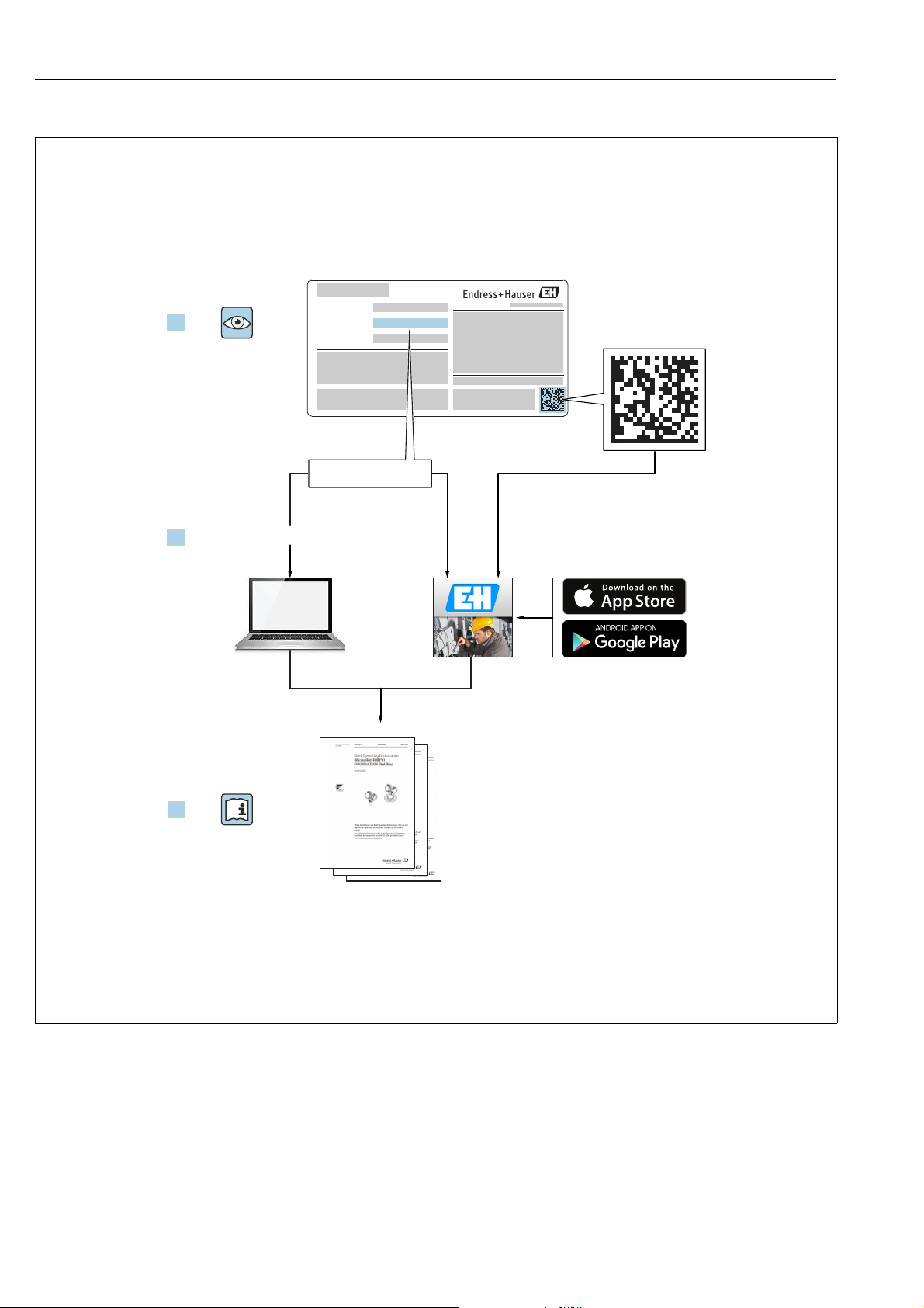
1.
Order code:
Ext. ord. cd.:
Ser. no.:
www.endress.com/deviceviewer Endress+Hauser Operations App
XXXXXXXXXXXX
XXXXX-XXXXXX
XXX.XXXX.XX
Serial number
2.
3.
Make sure the document is stored in a safe place such that it is always available when
working on or with the device.
To avoid danger to individuals or the facility, read the "Basic safety instructions" section
carefully, as well as all other safety instructions in the document that are specific to
working procedures.
The manufacturer reserves the right to modify technical data without prior notice. Your
Endress+Hauser distributor will supply you with current information and updates to
these Instructions.
A0023555
2 Endress+Hauser
Page 3

Cerabar M, Deltabar M, Deltapilot M
Table of contents
1 Document information . . . . . . . . . . . . . . 4
1.1 Document function . . . . . . . . . . . . . . . . . . . . . . . . . . 4
1.2 Symbols used . . . . . . . . . . . . . . . . . . . . . . . . . . . . . . . 4
2 Basic safety instructions . . . . . . . . . . . . . 6
2.1 Requirements concerning the staff . . . . . . . . . . . . . 6
2.2 Designated use . . . . . . . . . . . . . . . . . . . . . . . . . . . . . 6
2.3 Workplace safety . . . . . . . . . . . . . . . . . . . . . . . . . . . 6
2.4 Operational safety . . . . . . . . . . . . . . . . . . . . . . . . . . . 6
2.5 Hazardous area . . . . . . . . . . . . . . . . . . . . . . . . . . . . . 7
2.6 Product safety . . . . . . . . . . . . . . . . . . . . . . . . . . . . . . 7
2.7 Functional Safety SIL (optional) . . . . . . . . . . . . . . . 7
3 Identification . . . . . . . . . . . . . . . . . . . . . . 8
3.1 Product identification . . . . . . . . . . . . . . . . . . . . . . . . 8
3.2 Device designation . . . . . . . . . . . . . . . . . . . . . . . . . . 8
3.3 Scope of delivery . . . . . . . . . . . . . . . . . . . . . . . . . . 11
3.4 CE mark, Declaration of Conformity . . . . . . . . . . 11
4 Installation . . . . . . . . . . . . . . . . . . . . . . . 12
4.1 Incoming acceptance . . . . . . . . . . . . . . . . . . . . . . 12
4.2 Storage and transport . . . . . . . . . . . . . . . . . . . . . . 12
4.3 Installation conditions . . . . . . . . . . . . . . . . . . . . . 12
4.4 General installation instructions . . . . . . . . . . . . . 13
4.5 Installing Cerabar M . . . . . . . . . . . . . . . . . . . . . . . 14
4.6 Installing Deltabar M . . . . . . . . . . . . . . . . . . . . . . 24
4.7 Installing Deltapilot M . . . . . . . . . . . . . . . . . . . . . 32
4.8 Mounting of the profile seal for universal process
mounting adapter . . . . . . . . . . . . . . . . . . . . . . . . . 37
4.9 Closing the housing cover . . . . . . . . . . . . . . . . . . 37
4.10 Post-installation check . . . . . . . . . . . . . . . . . . . . . 37
8.3 Commissioning with an operating menu . . . . . . . 63
8.4 Position zero adjustment . . . . . . . . . . . . . . . . . . . . 64
8.5 Level measurement (Cerabar M and Deltapilot M)
65
8.6 Linearization . . . . . . . . . . . . . . . . . . . . . . . . . . . . . . 75
8.7 Pressure measurement . . . . . . . . . . . . . . . . . . . . . 79
8.8 Electrical differential pressure measurement with
gauge pressure sensors (Cerabar M or Deltapilot M)
81
8.9 Differential pressure measurement (Deltabar M) .
83
8.10 Flow measurement (Deltabar M) . . . . . . . . . . . . . 85
8.11 Level measurement (Deltabar M) . . . . . . . . . . . . . 88
8.12 Backup or duplicate device data . . . . . . . . . . . . . . 99
9 Maintenance . . . . . . . . . . . . . . . . . . . . 100
9.1 Cleaning instructions . . . . . . . . . . . . . . . . . . . . . 100
9.2 Exterior cleaning . . . . . . . . . . . . . . . . . . . . . . . . . 100
10 Troubleshooting . . . . . . . . . . . . . . . . . 101
10.1 Messages . . . . . . . . . . . . . . . . . . . . . . . . . . . . . . . 101
10.2 Response of output to errors . . . . . . . . . . . . . . . 103
10.3 Repair . . . . . . . . . . . . . . . . . . . . . . . . . . . . . . . . . . 103
10.4 Repair of Ex-certified devices . . . . . . . . . . . . . . 103
10.5 Spare Parts . . . . . . . . . . . . . . . . . . . . . . . . . . . . . . 104
10.6 Return . . . . . . . . . . . . . . . . . . . . . . . . . . . . . . . . . 104
10.7 Disposal . . . . . . . . . . . . . . . . . . . . . . . . . . . . . . . . 104
10.8 Software history . . . . . . . . . . . . . . . . . . . . . . . . . 105
11 Technical data . . . . . . . . . . . . . . . . . . . 107
12 Appendix . . . . . . . . . . . . . . . . . . . . . . . 108
5 Electrical connection . . . . . . . . . . . . . . . 38
5.1 Connecting the device . . . . . . . . . . . . . . . . . . . . . 38
5.2 Connecting the measuring unit . . . . . . . . . . . . . . 40
5.3 Overvoltage protection (optional) . . . . . . . . . . . . 42
5.4 Post-connection check . . . . . . . . . . . . . . . . . . . . . 44
12.1 Overview of operating menu . . . . . . . . . . . . . . . 108
12.2 Description of parameters . . . . . . . . . . . . . . . . . 116
Index . . . . . . . . . . . . . . . . . . . . . . . . . . . 140
6 Operation. . . . . . . . . . . . . . . . . . . . . . . . . 45
6.1 Operating options . . . . . . . . . . . . . . . . . . . . . . . . . 45
6.2 Operation without operating menu . . . . . . . . . . 46
6.3 Operation with an operating menu . . . . . . . . . . 48
7 Integrating transmitter using HART®
protocol . . . . . . . . . . . . . . . . . . . . . . . . . . 57
7.1 HART process variables and measured values . 57
7.2 Device variables and measured values . . . . . . . . 58
8 Commissioning. . . . . . . . . . . . . . . . . . . . 59
8.1 Function check . . . . . . . . . . . . . . . . . . . . . . . . . . . 59
8.2 Commissioning without an operating menu . . . 60
Endress+Hauser 3
Page 4
Document information Cerabar M, Deltabar M, Deltapilot M
DANGER
WARNING
CAUTION
NOTICE
)
1 Document information
1.1 Document function
These Operating Instructions contain all the information that is required in various phases
of the life cycle of the device: from product identification, incoming acceptance and storage,
to mounting, connection, operation and commissioning through to troubleshooting,
maintenance and disposal.
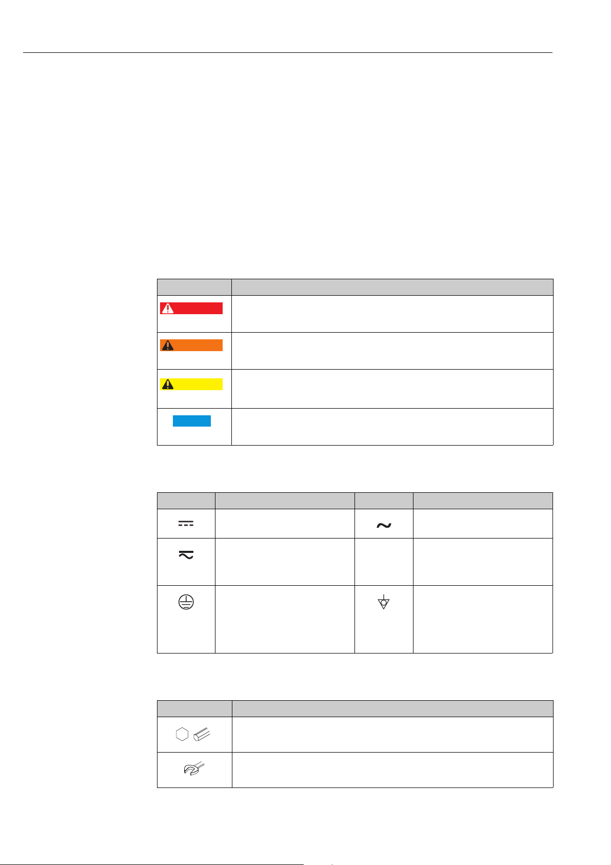
1.2 Symbols used
1.2.1 Safety symbols
Symbol Meaning
DANGER!
A0011189-DE
A0011190-DE
A0011191-DE
A0011192-DE
This symbol alerts you to a dangerous situation. Failure to avoid this situation will result in
seriousor fatal injury.
WARNING!
This symbol alerts you to a dangerous situation. Failure to avoid this situation can result in
seriousor fatal injury.
CAUTION!
This symbol alerts you to a dangerous situation. Failure to avoid this situation can result in
minoror medium injury.
NOTICE!
This symbol contains information on procedures and other facts which do not result in
personalinjury.
1.2.2 Electrical symbols
Symbol Meaning Symbol Meaning
Direct current Alternating current
Direct current and alternating current Ground connection
Protective ground connection
A terminal which must be connected
to ground prior to establishing any
other connections.
1.2.3 Tool symbols
Symbol Meaning
Allen key
A0011221
Hexagon wrench
A grounded terminal which, as far as
the operator is concerned, is grounded
via a grounding system.
Equipotential connection
A connection that has to be connected
to the plant grounding system: This
may be a potential equalization line or
a star grounding system depending on
national or company codes of practice.
A0011222
4 Endress+Hauser
Page 5
Cerabar M, Deltabar M, Deltapilot M Document information
1.
2.
1.
2.
t 85°C>
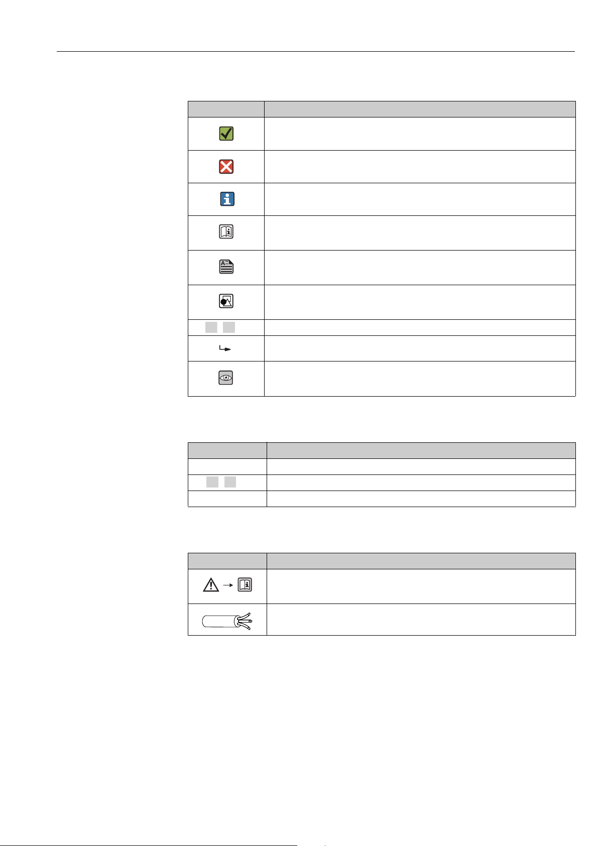
1.2.4 Symbols for certain types of information
Symbol Meaning
Permitted
Indicates procedures, processes or actions that are permitted.
A0011182
Forbidden
Indicates procedures, processes or actions that are forbidden.
A0011184
Tip
Indicates additional information.
A0011193
Reference to documentation
A0015482
Reference to page
A0015484
Reference to graphic
A0015487
, , ... Series of steps
Result of a sequence of actions
A0018343
Visual inspection
A0015502
1.2.5 Symbols in graphics
Symbol Meaning
1, 2, 3, 4, ... Item numbers
, , ... Series of steps
A, B, C, D, ... Views
1.2.6 Symbols at the device
Symbol Meaning
Safety instructions
Observe the safety instructions contained in the associated Operating Instructions.
A0019159
Connecting cable immunity to temperature change
Indicates that the connecting cables have to withstand a temperature of 85°C at least.
1.2.7 Registered trademarks
KALREZ®, VITON®, TEFLON
Registered label of E.I. Du Pont de Nemours & Co., Wilmington, USA
TRI-CLAMP
®
Registered label of Ladish & Co., Inc., Kenosha, USA
®
HART
Registered trademark of the FieldComm Group, Austin, USA
GORE-TEX
®
Registered label of W.L. Gore & Associates, Inc., USA
®
Endress+Hauser 5
Page 6

Basic safety instructions Cerabar M, Deltabar M, Deltapilot M
2 Basic safety instructions
2.1 Requirements concerning the staff
The personnel for installation, commissioning, diagnostics and maintenance must fulfill the
following requirements:
• Trained, qualified specialists: must have a relevant qualification for this specific function
and task
• Are authorized by the plant owner/operator
• Are familiar with federal/national regulations
• Before beginning work, the specialist staff must have read and understood the instructions
in the Operating Instructions and supplementary documentation as well as in the
certificates (depending on the application)
• Following instructions and basic conditions
The operating personnel must fulfill the following requirements:
• Being instructed and authorized according to the requirements of the task by the facility's
owner-operator
• Following the instructions in these Operating Instructions
2.2 Designated use
The Cerabar M is a pressure transmitter for measuring level and pressure.
The Deltabar M is a differential pressure transmitter for measuring differential pressure,
flow and level.
The Deltapilot M is a hydrostatic pressure sensor for measuring level and pressure.
2.2.1 Incorrect use
The manufacturer is not liable for damage caused by improper or non-designated use.
Verification for borderline cases:
For special fluids and fluids for cleaning, Endress+Hauser is glad to provide assistance in
verifying the corrosion resistance of fluid-wetted materials, but does not accept any
warranty or liability.
2.3 Workplace safety
For work on and with the device:
• Wear the required personal protective equipment according to federal/national
regulations.
• Switch off the supply voltage before connecting the device.
2.4 Operational safety
Risk of injury!
‣ Operate the device in proper technical condition and fail-safe condition only.
‣ The operator is responsible for interference-free operation of the device.
‣ Only disassemble the device in pressurless condition!
Conversions to the device
Unauthorized modifications to the device are not permitted and can lead to unforeseeable
dangers:
‣ If, despite this, modifications are required, consult with Endress+Hauser.
Repair
To ensure continued operational safety and reliability,
6 Endress+Hauser
Page 7

Cerabar M, Deltabar M, Deltapilot M Basic safety instructions
‣ Carry out repairs on the device only if they are expressly permitted.
‣ Observe federal/national regulations pertaining to repair of an electrical device.
‣ Use original spare parts and accessories from Endress+Hauser only.
2.5 Hazardous area
To eliminate a danger for persons or for the facility when the device is used in the hazardous
area (e.g. explosion protection, pressure vessel safety):
• Based on the nameplate, check whether the ordered device is permitted for the intended
use in the hazardous area.
• Observe the specifications in the separate supplementary documentation that is an
integral part of these Instructions.
2.6 Product safety
This measuring device is designed in accordance with good engineering practice to meet
state-of-the- art safety requirements, has been tested, and left the factory in a condition in
which they are safe to operate. It fulfills general safety requirements and legal requirements.
It also conforms to the EC directives listed in the device-specific EC declaration of conformity.
Endress+Hauser confirms this fact by applying the CE mark.
2.7 Functional Safety SIL (optional)
If using devices for applications with safety integrity, the Functional Safety Manual
(SD00347P/00/EN) must be observed thoroughly.
Endress+Hauser 7
Page 8

Identification Cerabar M, Deltabar M, Deltapilot M
3 Identification
3.1 Product identification
The following options are available for identification of the measuring device:
• Nameplate specifications
• Order code with breakdown of the device features on the delivery note
• Enter serial numbers from nameplates in W@M Device Viewer
(www.endress.com/deviceviewer): All information about the measuring device is
displayed.
For an overview of the technical documentation provided, enter the serial number from the
nameplates in the W@M Device Viewer (www.endress.com/deviceviewer).
3.2 Device designation
3.2.1 Device identification via the nameplate
• The MWP (maximum working pressure) is specified on the nameplate. This value refers
to a reference temperature of 20°C (68°F) or 100°F (38 °C) for ANSI flanges.
• The pressure values permitted at higher temperatures can be found in the following
standards:
– EN 1092-1: 2001 Tab. 18
– ASME B 16.5a – 1998 Tab. 2-2.2 F316
– ASME B 16.5a – 1998 Tab. 2.3.8 N10276
– JIS B 2220
• The test pressure corresponds to the over pressure limit (OPL) of the device = MWP x 1.5
2)
.
• The Pressure Equipment Directive (EC Directive 97/23/EC) uses the abbreviation "PS". The
abbreviation "PS" corresponds to the MWP (maximum working pressure) of the measuring
device.
1)
1) With regard to their stability-temperature property, the materials 1.4435 and 1.4404 are grouped together
under 13EO in EN 1092-1 Tab. 18. The chemical composition of the two materials can be identical.
2) The equation does not apply for PMP51 and PMP55 with a 40 bar (600 psi) or a 100 bar (1500 psi) measuring
cell.
8 Endress+Hauser
Page 9
Cerabar M, Deltabar M, Deltapilot M Identification
ex works FW:
Dev.Rev.:
250002755-C
Ext. order code:
Ser. no.:
U=
Span
P
MWP
Order code:
Made in Germany, D-79689 Maulburg
Mat.:
250002756-E
L=
1
2
3
4
5 6 7
8 9 10
11
12
13
14
15
16
17
18
18
Pmax
Tmax
for oxygen service
Bei Sauerstoffeinsatz/
1
2
3
Aluminum housing
A0030017
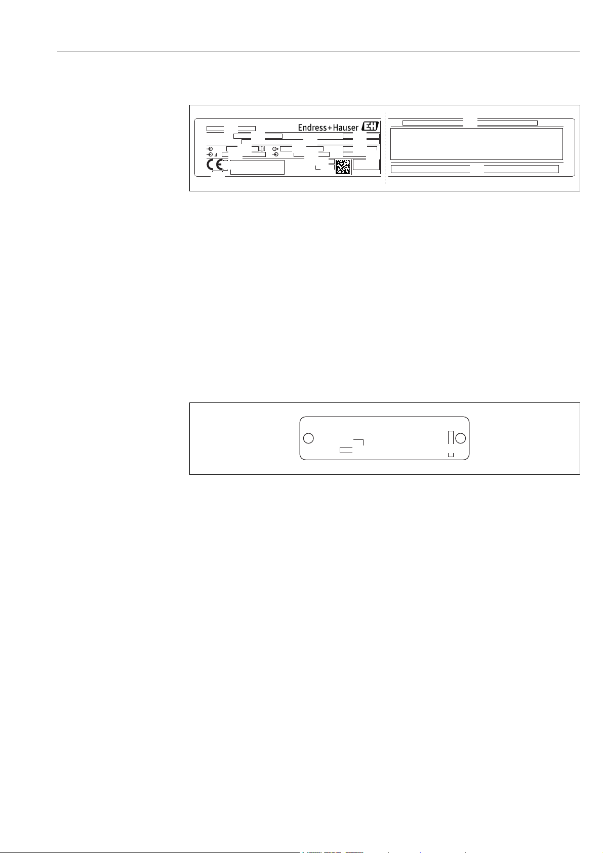
Fig. 1: Nameplate
1 Device name
2 Order code (for re-orders)
3 Serial number (for identification)
4 Extended order code (complete)
5 MWP (maximum working pressure)
6 Electronic version (output signal)
7Min./max. span
8 Nominal measuring range
9 Supply voltage
10 Unit of length
11 ID number of notified body with regard to ATEX (optional)
12 ID number of notified body with regard to Pressure Equipment Directive (optional)
13 Approvals
14 Device version
15 Software version
16 Degree of protection
17 Wetted materials
18 Approval-specific information
Devices suitable for oxygen applications are fitted with an additional nameplate.
Fig. 2: Additional nameplate for devices suitable for oxygen applications
1 Maximum pressure for oxygen applications
2 Maximum temperature for oxygen applications
3 Layout identification of the nameplate
A0030019
Endress+Hauser 9
Page 10
Identification Cerabar M, Deltabar M, Deltapilot M
002757-A
p
Order code:
Ext. order code:
Ser. no.:
MWP
D-79689 Maulburg
Made in Germany,
ex works FW
U=
Dev.Rev.:
L=
Span
Mat.:
002758-C
1
2
3
4
4
4
5
6
7
8
9
10
11
12
13
14
15
16
17
18
12
002759-B
1
1
Stainless steel housing, hygienic
A0030021
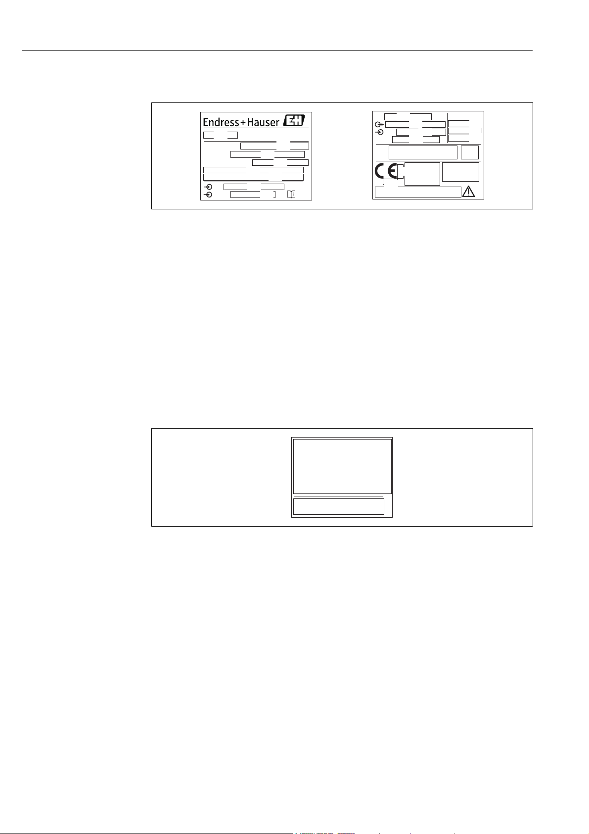
Fig. 3: Nameplate for Cerabar M and Deltapilot M
1 Device name
2 Order code (for re-orders)
3 Serial number (for identification)
4 Extended order code (complete)
5 Nominal measuring range
6 MWP (maximum working pressure)
7Length data
8 Electronic version (output signal)
9 Supply voltage
10 Min./max. span
11 Wetted materials
12 Approval-specific information
13 ID number of notified body with regard to ATEX (optional)
14 ID number of notified body with regard to Pressure Equipment Directive (optional)
15 Approvals
16 Software version
17 Device version
18 Degree of protection
Devices with certificates are fitted with an additional plate.
Fig. 4: Additional nameplate for devices with certificates
1 Approval-specific information
3.2.2 Identifying the sensor type
In the case of gauge pressure sensors, the "Pos. zero adjust" parameter appears in the
operating menu ("Setup" -> "Pos. zero adjust").
In the case of absolute pressure sensors, the "Calib. offset" parameter appears in the
operating menu ("Setup" -> "Calib. offset").
A0030024
10 Endress+Hauser
Page 11

Cerabar M, Deltabar M, Deltapilot M Identification
3.3 Scope of delivery
The scope of delivery comprises:
• Device
• Optional accessories
Documentation supplied:
• Operating Instruction BA00382P is available on the Internet.
See: www.endress.com Download
• Brief Operating Instruction: KA01030P Cerabar M / KA01027P Deltabar M / KA01033P
Deltapilot M
• Final inspection report
• Additional Safety Instructions for ATEX, IECEx and NEPSI devices
• Optional: factory calibration form, test certificates
3.4 CE mark, Declaration of Conformity
The devices are designed to meet state-of-the-art safety requirements, have been tested and
left the factory in a condition in which they are safe to operate. The devices comply with the
applicable standards and regulations as listed in the EC Declaration of Conformity and thus
comply with the statutory requirements of the EC Directives. Endress+Hauser confirms the
conformity of the device by affixing to it the CE mark.
Endress+Hauser 11
Page 12

Installation Cerabar M, Deltabar M, Deltapilot M
WARNING
!
4Installation
4.1 Incoming acceptance
• Check the packaging and the contents for damage.
• Check the shipment, make sure nothing is missing and that the scope of supply matches
your order.
4.2 Storage and transport
4.2.1 Storage
The device must be stored in a dry, clean area and protected against damage from impact
(EN 837-2).
Storage temperature range:
See Technical Information for Cerabar M TI00436P / Deltabar M TI00434P / Deltapilot M
TI00437P.
4.2.2 Transport
Incorrect transportation
Housing, diaphragm and capillaries may become damaged, and there is a risk of injury!
‣ Transport the measuring device to the measuring point in its original packaging or by the
process connection.
‣ Follow the safety instructions and transport conditions for devices weighing more than
18 kg (39.6 lbs).
‣ Do not use capillaries as a carrying aid for the diaphragm seals.
4.3 Installation conditions
4.3.1 Dimensions
For dimensions, please refer to the Technical Information for Cerabar M TI00436P /
Deltabar M TI00434P / Deltapilot M TI00437P, "Mechanical construction" section.
12 Endress+Hauser
Page 13

Cerabar M, Deltabar M, Deltapilot M Installation
WARNING
!
WARNING
!
4.4 General installation instructions
• Devices with a G 1 1/2 thread:
When screwing the device into the tank, the flat seal has to be positioned on the sealing
surface
of the process connection. To avoid additional strain on the process isolating diaphragm,
the thread should never be sealed with hemp or similar materials.
• Devices with NPT threads:
– Wrap Teflon tape around the thread to seal it.
– Tighten the device at the hexagonal bolt only. Do not turn at the housing.
– Do not overtighten the thread when screwing. Max. torque: 20 to 30 Nm (14.75 to
22.13 lbf ft)
4.4.1 Mounting sensor modules with PVDF thread
Risk of damage to process connection!
Risk of injury!
‣ Sensor modules with PVDF process connections with threaded connection must be
installed with the mounting bracket provided!
Material fatigue from pressure and temperature!
Risk of injury if parts burst! The thread can become loose if exposed to high pressure and
temperatures.
‣ The integrity of the thread must be checked regularly and the thread may need to be re-
tightened with the maximum tightening torque of 7 Nm (5.16 lbf ft). Teflon tape is
recommended for sealing the ½" NPT thread.
Endress+Hauser 13
Page 14
Installation Cerabar M, Deltabar M, Deltapilot M
NOTICE
1
1
1
4.5 Installing Cerabar M
• Due to the orientation of the Cerabar M, there may be a shift in the zero point, i.e. when
the container is empty or partially full, the measured value does not display zero. You can
correct this zero point shift ä 47, Section "Function of the operating elements" or
ä 64, Section 8.4 "Position zero adjustment".
• For PMP55, please refer to Section 4.5.2 "Installation instructions for devices with
diaphragm seals – PMP55", ä 17.
• Endress+Hauser offers a mounting bracket for installing on pipes or walls.
ä 21, Section 4.5.5 "Wall and pipe mounting (optional)".
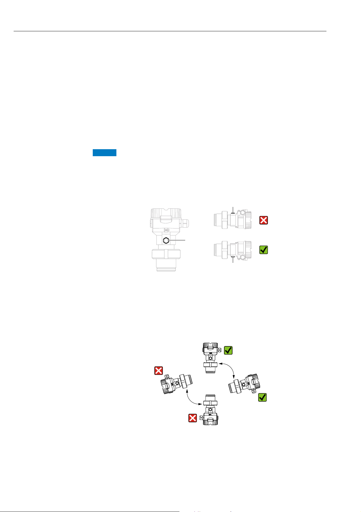
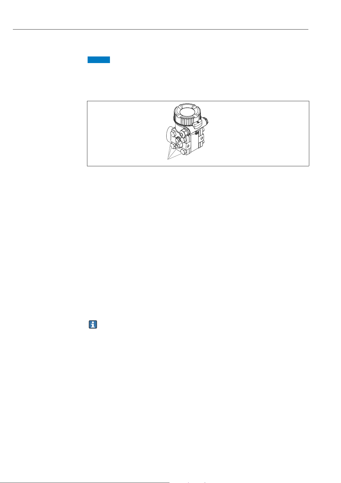
4.5.1 Installation instructions for devices without diaphragm seals –
PMP51, PMC51
Damage to the device!
If a heated Cerabar M is cooled during the cleaning process (e.g. by cold water), a vacuum
develops for a short time, whereby moisture can penetrate the sensor through the pressure
compensation (1).
‣ If this is the case, mount the Cerabar M with the pressure compensation (1) pointing
downwards.
®
• Keep the pressure compensation and GORE-TEX
• Cerabar M transmitters without diaphragm seals are mounted as per the norms for a
manometer (DIN EN 837-2). We recommend the use of shutoff devices and siphons. The
orientation depends on the measuring application.
• Do not clean or touch process isolating diaphragms with hard or pointed objects.
• The device must be installed as follows in order to comply with the cleanability
requirements of the ASME-BPE (Part SD Cleanability):
filter (1) free from contamination.
14 Endress+Hauser
Page 15

Cerabar M, Deltabar M, Deltapilot M Installation
1
2
1
1
2
2
3
4
Pressure measurement in gases
A0028473
Fig. 5: Measuring arrangement for pressure measurement in gases
1 Cerabar M
2Shutoff device
Mount the Cerabar M with the shutoff device above the tapping point so that any condensate
can flow into the process.
Pressure measurement in steams
Fig. 6: Measuring arrangement for pressure measurement in steams
1 Cerabar M
2Shutoff device
3 U-shaped siphon
4 Circular siphon
A0028474
• Mount Cerabar M with siphon above the tapping point.
• Fill the siphon with liquid before commissioning.
The siphon reduces the temperature to almost the ambient temperature.
Endress+Hauser 15
Page 16
Installation Cerabar M, Deltabar M, Deltapilot M
1
2
3
Pressure measurement in liquids
A0028491
Fig. 7: Measuring arrangement for pressure measurement in liquids
1 Cerabar M
2 Shutoff device
• Mount Cerabar M with shutoff device below or at the same level as the tapping point.
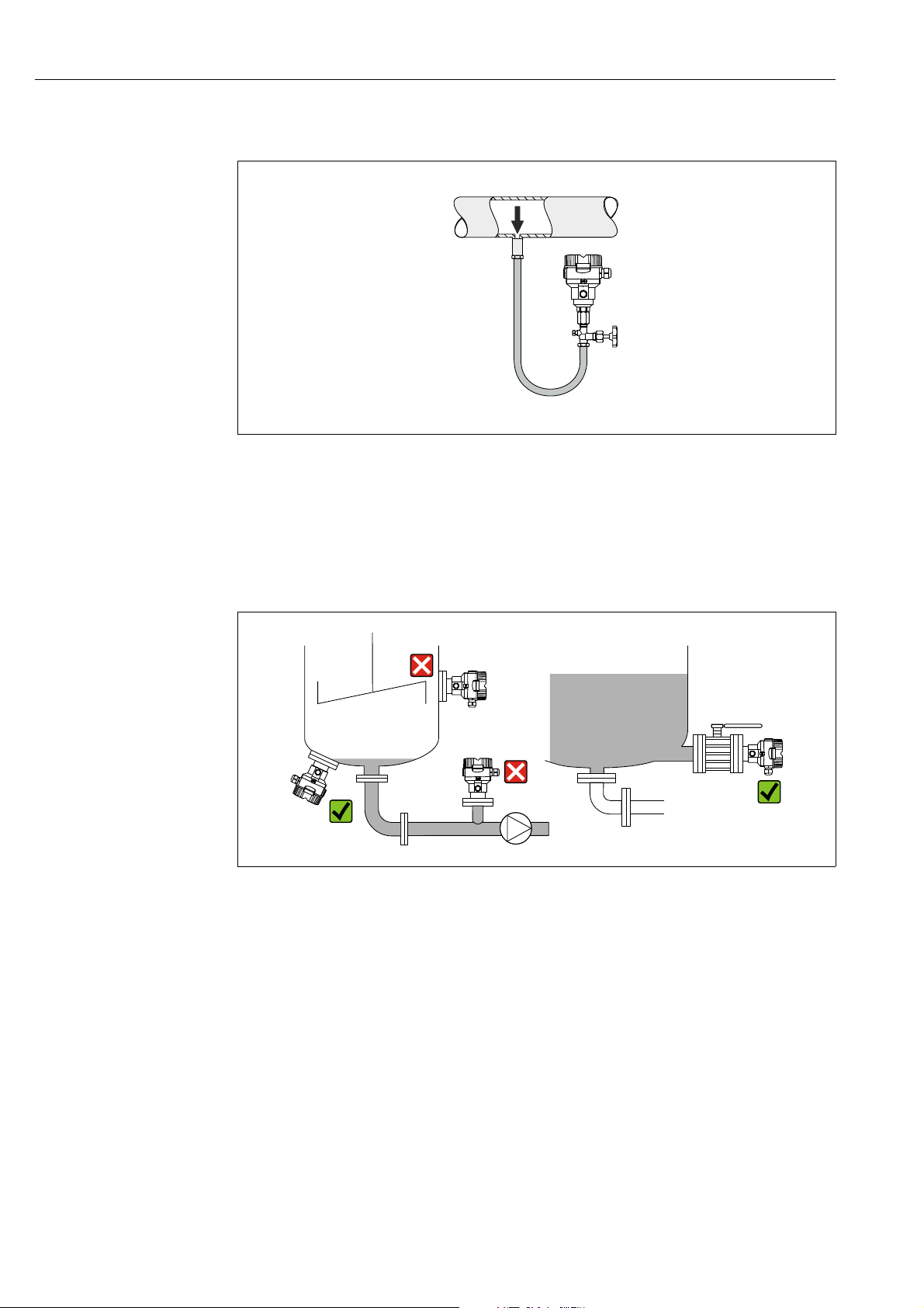
Level measurement
A0028492
Fig. 8: Measuring arrangement for level
• Always install the Cerabar M below the lowest measuring point.
• Do not mount the device in the filling curtain or at a point in the tank which could be
affected by pressure pulses from an agitator.
• Do not mount the device in the suction area of a pump.
• The calibration and functional test can be carried out more easily if you mount the device
downstream of a shutoff device.
16 Endress+Hauser
Page 17

Cerabar M, Deltabar M, Deltapilot M Installation
NOTICE
NOTICE
4.5.2 Installation instructions for devices with diaphragm seals –
PMP55
• Cerabar M devices with diaphragm seals are screwed in, flanged or clamped, depending on
the type of diaphragm seal.
• Please note that the hydrostatic pressure of the liquid columns in the capillaries can cause
zero point shift. The zero point shift can be corrected.
• Do not clean or touch the process isolating diaphragm of the diaphragm seal with hard or
pointed objects.
• Do not remove process isolating diaphragm protection until shortly before installation.
Improper handling!
Damage to the device!
‣ A diaphragm seal and the pressure transmitter together form a closed, oil-filled
calibrated system. The fill fluid hole is sealed and may not be opened.
‣ When using a mounting bracket, sufficient strain relief must be ensured for the
capillaries in order to prevent the capillary bending down (bending radius 100
(3.94 in)).
‣ Please observe the application limits of the diaphragm seal filling oil as detailed in the
Technical Information for Cerabar M TI00436P, "Planning instructions for diaphragm
seal systems" section.
In order to obtain more precise measurement results and to avoid a defect in the device,
mount the capillaries as follows:
‣ Vibration-free (in order to avoid additional pressure fluctuations)
‣ Not in the vicinity of heating or cooling lines
‣ Insulate if the ambient temperature is below or above the reference temperature
‣ With a bending radius of 100 mm (3.94 in).
‣ Do not use the capillaries as a carrying aid for the diaphragm seals!
Endress+Hauser 17
Page 18

Installation Cerabar M, Deltabar M, Deltapilot M
H1
1
2
3
4
5
A
B
0.0
2.0
4.0
6.0
8.0
10.0
12.0
50 100 300 400 500 600 700 800 900 1000200
[mbar
abs
]
[m]
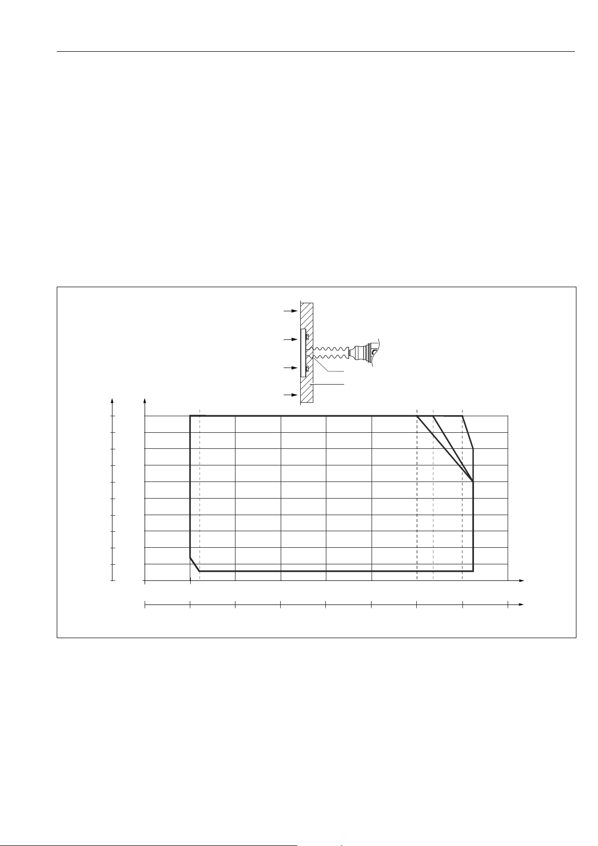
Vacuum application
For applications under vacuum, Endress+Hauser recommends mounting the pressure
transmitter below the diaphragm seal. This prevents vacuum loading of the diaphragm seal
caused by the presence of fill fluid in the capillary.
When the pressure transmitter is mounted above the diaphragm seal, the maximum height
difference H1 in accordance with the illustrations below must not be exceeded.
A0023994
Fig. 9: Installation above the lower diaphragm seal
The maximum height difference depends on the density of the filling oil and the smallest
ever pressure that is permitted to occur at the diaphragm seal (empty vessel), see illustration
below:
Fig. 10: Diagram of maximum installation height above the lower diaphragm seal for vacuum applications depending on the
A Height difference H1
B Pressure at diaphragm seal
1 Low temperature oil
2 Vegetable oil
3 Silicone oil
4 High-temperature oil
5Inert oil
pressure at the diaphragm seal on the positive side
18 Endress+Hauser
A0023986-en
Page 19
Cerabar M, Deltabar M, Deltapilot M Installation
T
p
T
a
+212
+176+140+104+68+32-4-40-76
+400
+350
+300
+250
+200
+150
+100
+50
0
-50
-100
+752
+662
+572
+482
+392
+302
+212
+122
+32
-58
-148
[°C]
[°F]
[°C][°F]
+100+80+60+40+20
0
-20-40-60
A
B
1
2
A
DE FG
C
B
Mounting with temperature isolator
Endress+Hauser recommends the use of temperature isolators in the event of constant
extreme medium temperatures which lead to the maximum permissible electronics
temperature of +85 °C (+185°F) being exceeded.
Depending on the filling oil used, diaphragm seal systems with temperature isolators can be
used for maximum temperatures of up to 400 °C (+752 °F). For the temperature
application limits, see technical Information, "Diaphragm seal filling oils" section.
To minimize the influence of rising heat, Endress+Hauser recommends the device be
mounted horizontally or with the housing pointing downwards. The additional installation
height also brings about a maximum zero point shift of 21 mbar (0.315 psi) due to the
hydrostatic column in the temperature isolator. You can correct this zero point shift at the
device.
The temperature restrictions are lowest with an insulation height of 30 mm (1.18 inch).
Full insulation exhibits virtually the same behavior as no insulation!
The temperature limits with an insulation height of 30 mm (1.18 inch) are illustrated in the
following graphic.
Fig. 11:
A Ambient temperature:
B Process temperature: max. 400 °C (752 °F), depending on the filling oil used
C Device with temperature isolator, material 316L (1.4404)
D Without isolation
E Maximum isolation
F 30 mm (1.18. inch) isolation
G Without isolation, maximum isolation, 30 mm (1.18. inch) isolation
1 Isolation heigth 30 mm (1.18. inch)
2Isolation material
85 °C (185 °F)
Endress+Hauser 19
A0031354
Page 20
Installation Cerabar M, Deltabar M, Deltapilot M
NOTICE
12
A
B
12
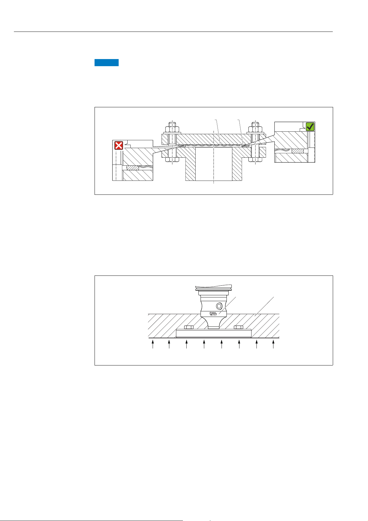
4.5.3 Seal for flange mounting
Corrupted measurement results.
The seal is not allowed to press against the process isolating diaphragm as this could affect
the measurement result.
‣ Ensure that the seal is not touching the process isolating diaphragm.
A0017743
Fig. 12:
1 Process isolating diaphragm
2Seal
4.5.4 Thermal insulation – PMP55
The PMP55 may only be insulated up to a certain height. The maximum permitted
insulation height is indicated on the devices and applies to an insulation material with a heat
conductivity 0.04 W/(m x K) and to the maximum permitted ambient and process
temperature. The data were determined under the most critical application "quiescent air".
A0020474
Fig. 13: Maximum permitted insulation height, here indicated on a PMP55 with a flange
A Ambient temperature:
B Process temperature: max. 400 °C (752°F), depending on the diaphragm seal filling oil used
1 Maximum permitted insulation height
2 Insulation material
70 °C (158°F)
20 Endress+Hauser
Page 21
Cerabar M, Deltabar M, Deltapilot M Installation
122 (4.8)
52 (2.05)
86 (3.39)
70 (2.76)
140 (5.51)
158 (6.22)
175 (6.89)
ø6 (0.24)
ø42...60 (1.65...2.36)
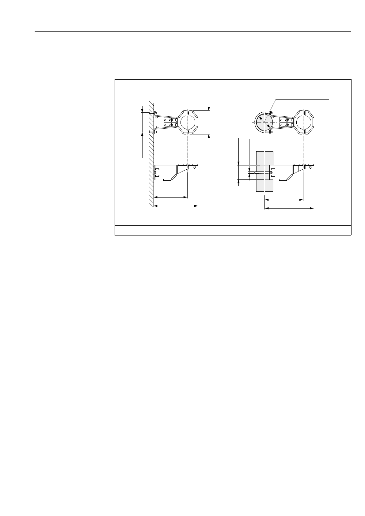
4.5.5 Wall and pipe mounting (optional)
Endress+Hauser offers a mounting bracket for installation on pipes or walls (for pipe
diameters from 1 ¼" to 2").
A0028493
Engineering unit mm (in)
Please note the following when mounting:
• Devices with capillary tubes: mount capillaries with a bending radius 100 mm (3.94 in).
• When mounting on a pipe, tighten the nuts on the bracket uniformly with a torque of at
least 5 Nm (3.69 lbs ft).
Endress+Hauser 21
Page 22
Installation Cerabar M, Deltabar M, Deltapilot M
r ³120 (4.72)
2
3
4
5
6
1
7
7
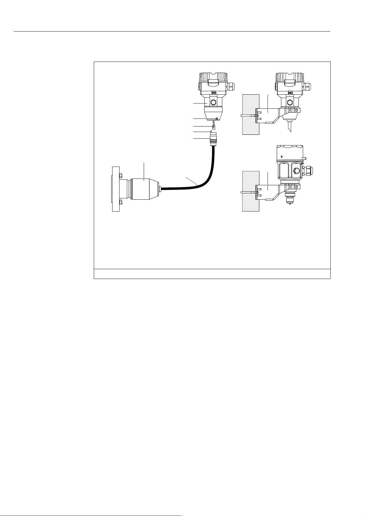
4.5.6 Assembling and mounting the "separate housing" version
Fig. 14: "Separate housing" version
1 In the case of the "separate housing" version, the sensor is delivered with the process connection and cable ready mounted.
2 Cable with connection jack
3 Pressure compensation
4 Connector
5Locking screw
6 Housing mounted with housing adapter, included
7 Mounting bracket provided, suitable for pipe and wall mounting (for pipe diameters from 1 ¼" up to 2")
Engineering unit mm (in)
Assembly and mounting
1. Insert the connector (item 4) into the corresponding connection jack of the cable
(item 2).
2. Plug the cable into the housing adapter (item 6).
3. Tighten the locking screw (item 5).
4. Mount the housing on a wall or pipe using the mounting bracket (item 7).
When mounting on a pipe, tighten the nuts on the bracket uniformly with a torque of
at least 5 Nm (3.69 lbs ft).
Mount the cable with a bending radius (r) 120 mm (4.72 in).
Routing the cable (e.g. through a pipe)
You require the cable shortening kit.
Order number: 71093286
For details on mounting, see SD00553P/00/A6.
A0028494
22 Endress+Hauser
Page 23

Cerabar M, Deltabar M, Deltapilot M Installation
A1
ø7.95 (0.31)
ø2.5 (0.1)
5 (0.2)
12 3
s1 a0.8
4.5.7 PMP51, version prepared for diaphragm seal mount –
welding recommendation
A0028495
Fig. 15: Version XSJ: prepared for diaphragm seal mount
1 Hole for fill fluid
2Bearing
3Setscrew
A1 See the "Welding recommendation" table below
Engineering unit mm (in)
Consecutive seam
no.
A1
for sensors
40 bar (600 psi)
Endress+Hauser recommends welding on the diaphragm seal as follows for the "XSJ Prepared for diaphragm seal mount" version in feature 110 "Process connections" in the order
code up to, and including, 40 bar (600 psi) sensors: the total welding depth of the fillet weld
is 1 mm (0.04 in) with an outer diameter of 16 mm (0.63 in). Welding is performed
according to the WIG method.
Sketch/welding groove shape,
dimension as per DIN 8551
Information on filling
The diaphragm seal must be filled as soon as it has been welded on.
• After welded into the process connection, the sensor asse mbly must be p rop erl y fil led wit h
a filling oil and sealed gas-tight with a sealing ball and lock screw.
Once the diaphragm seal has been filled, at the zero point the device display should not
exceed 10% of the full scale value of the cell measuring range. The internal pressure of the
diaphragm seal must be corrected accordingly.
• Adjustment / calibration:
– The device is operational once it has been fully assembled.
– Perform a reset. The device must then be calibrated to the process measuring range as
described in the Operating Instructions.
Base material matching Welding method
Adapter made of AISI 316L
(1.4435) to be welded to
diaphragm seal made of
AISI 316L (1.4435 or 1.4404)
A0024811
DIN EN ISO 24063
141 PB Inert gas
Welding
position
Inert gas,
additives
Ar/H 95/5
Additive:
ER 316L Si
(1.4430)
Endress+Hauser 23
Page 24
Installation Cerabar M, Deltabar M, Deltapilot M
NOTICE
1
4.6 Installing Deltabar M
Incorrect handling!
Damage of the device!
‣ Disassembly of the screws with item number (1) is not permissible under any
circumstances and will result in loss of warranty.
4.6.1 Installation position
• Due to the orientation of the Deltabar M, there may be a shift in the measured value, i.e.
when the container is empty, the measured value does not display zero. You may correct
this zero point shift by a position adjustment in one of the following ways:
– via the operation keys on the electronics module ( ä 47, "Function of the operating
elements")
– via the operating menu ( ä 64, "Position zero adjustment")
• General recommendations for routing the impulse piping can be found in DIN 19210
"Methods for measurement of fluid flow; differential piping for flow measurement devices"
or the corresponding national or international standards.
• Using a three-valve or five-valve manifold allows for easy commissioning, installation and
maintenance without interrupting the process.
• When routing the impulse piping outdoors, ensure that sufficient anti-freeze protection is
used, e.g. by using pipe heat tracing.
• Install the impulse piping with a monotonic gradient of at least 10%.
• Endress+Hauser offers a mounting bracket for installing on pipes or walls ( ä 29, "Wall
and pipe-mounting (option)").
Installation position for flow measurement
For more information about differential pressure flow measurement refer to following
documents:
• Differential pressure flow measurements with orifices: Technical Information TI00422P
• Differential pressure flow measurement with Pitot tubes: Technical Information TI00425P
24 Endress+Hauser
Page 25
Cerabar M, Deltabar M, Deltapilot M Installation
+
–
3
4
2
1
+
–
1
4
5
3
2
7
6
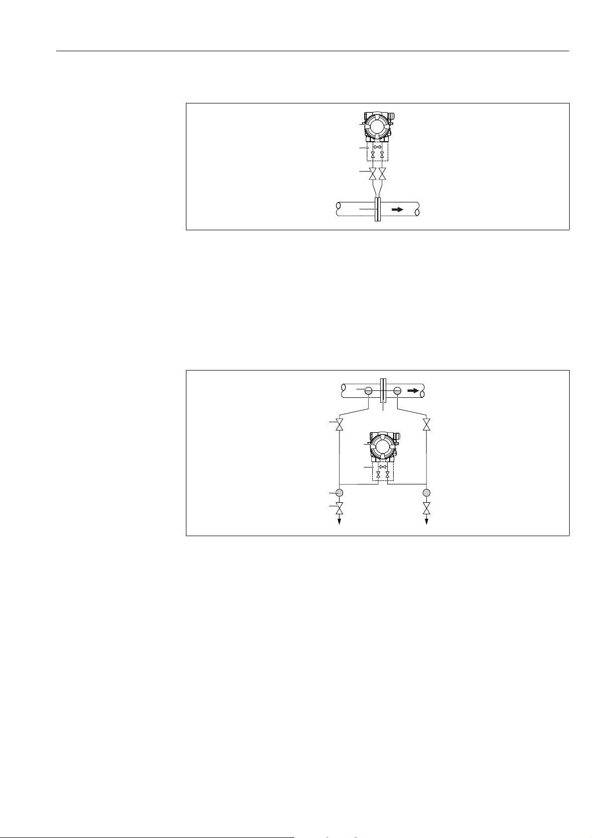
Flow measurement in gases
A0029783
Measuring layout for flow measurement in gases
1 Orifice plate or pitot tube
2 Shut-off valves
3Deltabar M
4 Three-valve manifold
• Mount the Deltabar M above the measuring point so that the condensate which may be
present, can run off into the process piping.
Flow measurement in steam
Measuring layout for flow measurement in steam
1 Orifice plate or pitot tube
2 Condensate traps
3 Shut-off valves
4 Deltabar M
5 Three-valve manifold
6Separator
7 Drain valves
A0029784
• Mount the Deltabar M below the measuring point.
• Mount the condensate traps at the same level as the tapping points and at the same
distance to the Deltabar M.
• Prior to commissioning, fill the impulse piping to the height of the condensate traps.
Endress+Hauser 25
Page 26
Installation Cerabar M, Deltabar M, Deltapilot M
+
–
1
3
4
2
6
5
–
+
min.
p
atm
5
4
p
atm
2
3
1
Flow measurement in liquids
A0029785
Measuring layout for flow measurement in liquids
1 Orifice plate or pitot tube
2 Shut-off valves
3Deltabar M
4 Three-valve manifold
5Separator
6 Drain valves
• Mount the Deltabar M below the measuring point so that the impulse piping is always
filled with liquid and gas bubbles can run back into the process piping.
• When measuring in media with solid parts, such as dirty liquids, installing separators and
drain valves is useful for capturing and removing sediment.
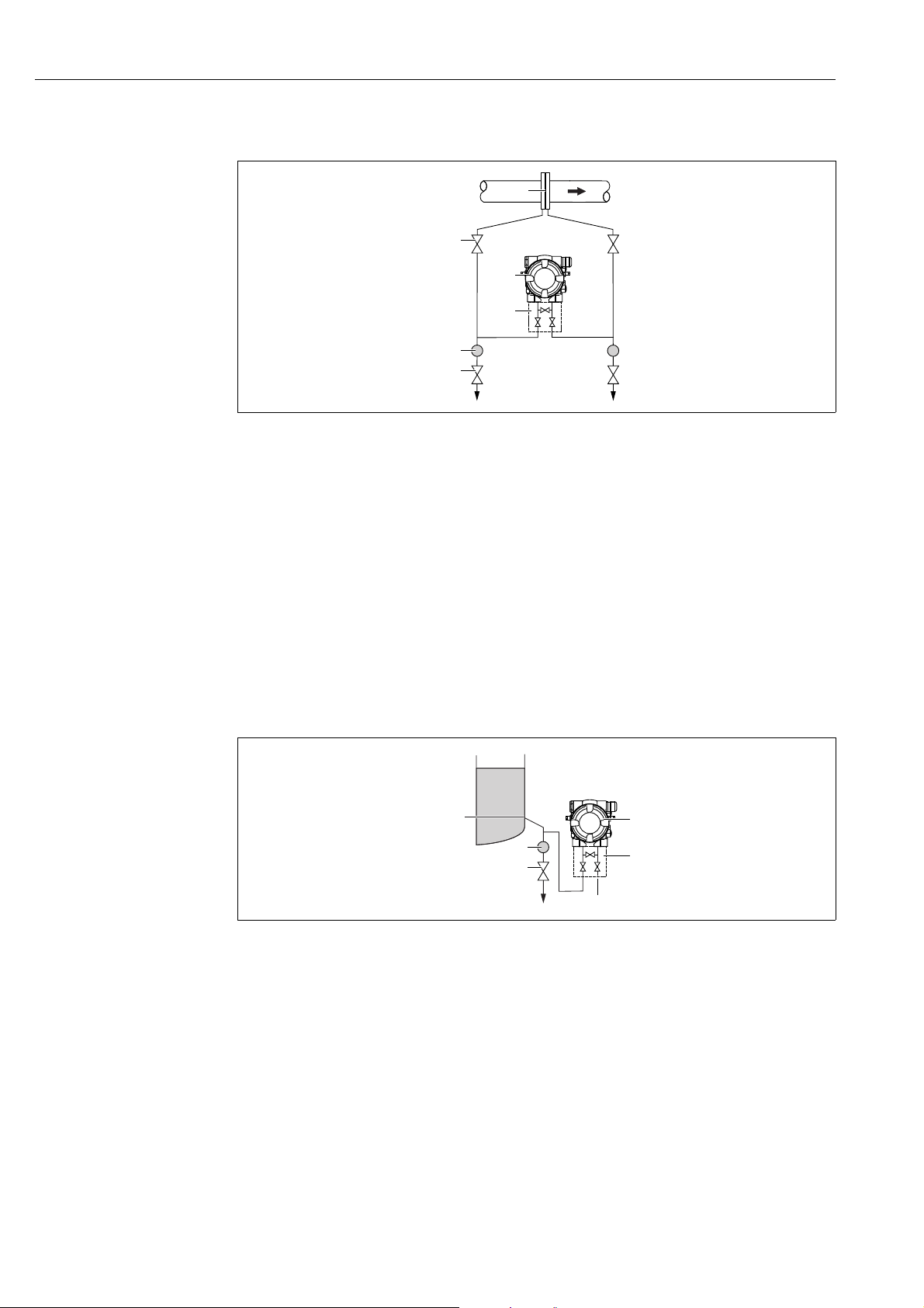
Installation position for level measurement
Level measurement in an open container
A0029787
Measuring layout for level measurement in open containers
1 The low-pressure side is open to atmospheric pressure
2Deltabar M
3 Three-valve manifold
4Separator
5 Drain valve
• Mount the Deltabar M below the lower measuring connection so that the impulse piping
is always filled with liquid.
• The low-pressure side is open to atmospheric pressure.
• When measuring in media with solid parts, such as dirty liquids, installing separators and
drain valves is useful for capturing and removing sediment.
26 Endress+Hauser
Page 27

Cerabar M, Deltabar M, Deltapilot M Installation
–
+
min.
5
4
2
1
3
–
max.
–
+
min.
5
6
3
4
–
max.
2
1
Level measurement in a closed container
A0029790
Measuring layout for level measurement in a closed container
1 Shut-off valves
2 Deltabar M
3 Three-valve manifold
4Separator
5 Drain valves
• Mount the Deltabar M below the lower measuring connection so that the impulse piping
is always filled with liquid.
• Always connect the low-pressure side above the maximum level.
• When measuring in media with solid parts, such as dirty liquids, installing separators and
drain valves is useful for capturing and removing sediment.
Level measurement in a closed container with superimposed steam
A0029791
Measuring layout for level measurement in a container with superimposed steam
1 Condensate trap
2 Shut-off valves
3 Deltabar M
4 Three-valve manifold
5Separator
6 Drain valves
• Mount the Deltabar M below the lower measuring connection so that the impulse piping
is always filled with liquid.
• Always connect the low-pressure side above the maximum level.
• A condensate trap ensures constant pressure on the low-pressure side.
Endress+Hauser 27
Page 28
Installation Cerabar M, Deltabar M, Deltapilot M
+
1
2
3
4
1
5
6
3
4
+
2
• When measuring in media with solid parts, such as dirty liquids, installing separators and
drain valves is useful for capturing and removing sediment.
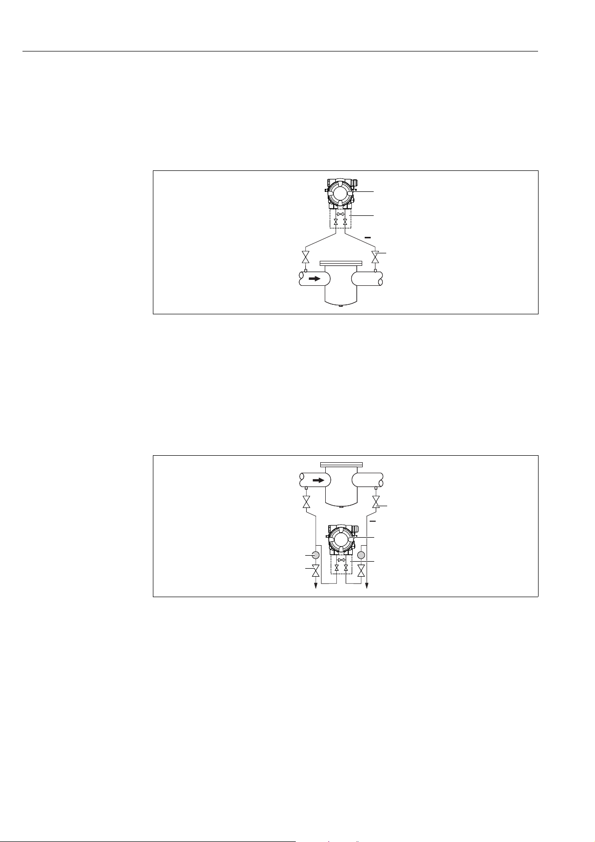
Installation position for differential pressure measurement
Differential pressure measurement in gases and steam
A0029792
Measuring layout for differential pressure measurement in gases and steam
1Deltabar M
2 Three-valve manifold
3 Shut-off valves
4 e.g. filter
• Mount the Deltabar M above the measuring point so that the condensate which may be
present, can run off into the process piping.
Differential pressure measurement in liquids
A0029798
Measuring layout for differential pressure measurement in liquids
1 e.g. filter
2 Shut-off valves
3Deltabar M
4 Three-valve manifold
5Separator
6 Drain valves
• Mount the Deltabar M below the measuring point so that the impulse piping is always
filled with liquid and gas bubbles can run back into the process piping.
• When measuring in media with solid parts, such as dirty liquids, installing separators and
28 Endress+Hauser
drain valves is useful for capturing and removing sediment.
Page 29

Cerabar M, Deltabar M, Deltapilot M Installation
4.6.2 Wall and pipe-mounting (option)
Endress+Hauser offers the following mounting brackets for installing the device on pipes or
walls:
Standard design Heavy duty design
A0031326 A0031327
When using a valve block, the block's dimensions must be taken into account.
Bracket for wall and pipe mounting including retaining bracket for pipe mounting and two
nuts.
material of the screws used to secure the device depend on the order code.
Technical data (e.g. dimensions or order numbers for screws) see accessory document
SD01553P/00/EN.
Please note the following when mounting:
• To prevent the mounting screws from scoring, lubricate them with a multi-purpose grease
prior to mounting.
• In the case of pipe mounting, the nuts on the bracket must be tightened uniformly with a
torque of at least 30 Nm (22.13 lbf ft).
• For installation purposes, only use the screws with item number (2) (see the following
diagram).
Endress+Hauser 29
Page 30

Installation Cerabar M, Deltabar M, Deltapilot M
NOTICE
1
1
2
2
2
1
Incorrect handling!
Damage of the device!
‣ Disassembly of the screws with item number (1) is not permissible under any
circumstances and will result in loss of warranty.
A0024167.eps
30 Endress+Hauser
Page 31

Cerabar M, Deltabar M, Deltapilot M Installation
1
1
2
4
3
1
2
3
3
4
C
A
B
4
Typical installation arrangements
A0023109
Abb. 16:
A Impulse line vertical, version V1, alignment 90°
B Impulse line horizontal, version H1, alignment 180°
C Impulse line horizontal, version H2, alignment 90°
1 Deltabar M
2 Adapter plate
3 Mounting bracket
4 Pressure line
Endress+Hauser 31
Page 32

Installation Cerabar M, Deltabar M, Deltapilot M
1
1
1
4.7 Installing Deltapilot M
• Due to the orientation of the Deltapilot M, there may be a shift in the zero point, i.e. when
the container is empty or partially full, the measured value does not display zero. You can
correct this zero point shift ä 47, Section "Function of the operating elements" or
ä 64, Section 8.4 "Position zero adjustment".
• The local display can be rotated in 90° stages.
• Endress+Hauser offers a mounting bracket for installing on pipes or walls.
ä 21, Section 4.5.5 "Wall and pipe mounting (optional)".
4.7.1 General installation instructions
• Do not clean or touch process isolating diaphragms with hard or pointed objects.
• The process isolating diaphragm in the rod and cable version is protected against
mechanical damage by a plastic cap.
• If a heated Deltapilot M is cooled during the cleaning process (e.g. by cold water), a vacuum
develops for a short time, whereby moisture can penetrate the sensor through the
pressure compensation (1). If this is the case, mount the Deltapilot M with the pressure
compensation (1) pointing downwards.
• Keep the pressure compensation and GORE-TEX
®
filter (1) free from contamination.
• The device must be installed as follows in order to comply with the cleanability
requirements of the ASME-BPE (Part SD Cleanibility).:
32 Endress+Hauser
Page 33

Cerabar M, Deltabar M, Deltapilot M Installation
4.7.2 FMB50
Level measurement
A0028492
Fig. 17: Measuring arrangement for level
• Always install the device below the lowest measuring point.
• Do not install the device at the following positions:
– in the filling curtain
– in the tank outflow
– in the suction area of a pump
– or at a point in the tank that can be affected by pressure pulses from the agitator
• The calibration and functional test can be carried out more easily if you mount the device
downstream of a shutoff device.
• Deltapilot M must be included in the insulation for media that can harden when cold.
Pressure measurement in gases
• Mount Deltapilot M with shutoff device above the tapping point so that any condensate
can flow into the process.
Pressure measurement in steams
• Mount Deltapilot M with siphon above the tapping point.
• Fill the siphon with liquid before commissioning.
The siphon reduces the temperature to almost the ambient temperature.
Pressure measurement in liquids
• Mount Deltapilot M with the shutoff device below or at the same level as the tapping point.
Endress+Hauser 33
Page 34

Installation Cerabar M, Deltabar M, Deltapilot M
L
E
17 (0.67)
1
2
3
4.7.3 FMB51/FMB52/FMB53
• When mounting rod and cable versions, make sure that the probe head is located at a point
as free as possible from flow. To protect the probe from impact resulting from lateral
movement, mount the probe in a guide tube (preferably made of plastic) or secure it with
a clamping fixture.
• In the case of devices for hazardous areas, comply strictly with the safety instructions
when the housing cover is open.
• The length of the extension cable or the probe rod is based on the planned level zero point.
The height of the protective cap must be taken into consideration when designing the
layout of the measuring point. The level zero point (E) corresponds to the position of the
process isolating diaphragm.
Level zero point = E; top of the probe = L.
4.7.4 Mounting the FMB53 with a suspension clamp
A0018793
Fig. 18: Mounting with a suspension clamp
1Extension cable
2 Suspension clamp
3 Clamping jaws
Mounting the suspension clamp:
1. Mount the suspension clamp (item 2). When selecting the place to fix the unit, take the
weight of the extension cable (item 1) and the device into account.
2. Raise the clamping jaws (item 3). Position the extension cable (item 1) between the
clamping jaws as illustrated in Figure.
3. Hold the extension cable in position (item 1) and push the clamping jaws (item 3) back
34 Endress+Hauser
down.
Tap the clamping jaws gently from above to fix them in place.
Page 35

Cerabar M, Deltabar M, Deltapilot M Installation
NOTICE
12
122 (4.8)
52 (2.05)
86 (3.39)
70 (2.76)
140 (5.51)
158 (6.22)
175 (6.89)
ø6 (0.24)
ø42...60 (1.65...2.36)
4.7.5 Seal for flange mounting
Distorted measurement results.
The seal is not allowed to press on the process isolating diaphragm as this could affect the
measurement result.
‣ Ensure that the seal is not touching the process isolating diaphragm.
A0017743
Fig. 19:
1 Process isolating diaphragm
2Seal
4.7.6 Wall and pipe mounting (optional)
Mounting bracket
Endress+Hauser offers a mounting bracket for installing on pipes or walls (for pipes from 1
1/4
" up to 2" diameter).
Maßeinheit mm (in)
In the case of pipe mounting, the nuts on the bracket must be tightened uniformly with a
torque of at least 5 Nm (3.69 lbf ft).
Endress+Hauser 35
A0028493
Page 36

Installation Cerabar M, Deltabar M, Deltapilot M
r ³120 (4.72)
2
3
4
5
6
1
7
7
4.7.7 Assembling and mounting the "separate housing" version
Fig. 20: "Separate housing" version
1 In the case of the "separate housing" version, the sensor is delivered with the process connection and cable ready mounted.
2 Cable with connection jack
3 Pressure compensation
4 Connector
5Locking screw
6 Housing mounted with housing adapter, included
7 Mounting bracket provided, suitable for pipe and wall mounting (for pipes from 1
Maßeinheit mm (in)
1/4
" up to 2" diameter)
Assembly and mounting
1. Insert the connector (item 4) into the corresponding connection jack of the cable (item
2).
2. Plug the cable into the housing adapter (item 6).
3. Tighten the locking screw (item 5).
4. Mount the housing on a wall or pipe using the mounting bracket (item 7).
When mounting on a pipe, tighten the nuts on the bracket uniformly with a torque of
at least 5 Nm (3.69 lbf ft).
Mount the cable with a bending radius (r) 120 mm (4.72 in).
Routing the cable (e.g. through a pipe)
You require the cable shortening kit.
Order number: 71093286
For details on mounting, see SD00553P/00/A6.
A0028494
4.7.8 Supplementary installation instructions
Sealing the probe housing
• Moisture must not penetrate the housing when mounting the device, establishing the
electrical connection and during operation.
• Always firmly tighten the housing cover and the cable entries.
36 Endress+Hauser
Page 37

Cerabar M, Deltabar M, Deltapilot M Installation
NOTICE
NOTICE
4.8 Mounting of the profile seal for universal process mounting adapter
For details on mounting, see KA00096F/00/A3.
4.9 Closing the housing cover
Devices with EPDM cover seal - transmitter leakiness!
Mineral-based, animal-based or vegetable-based lubricants cause the EPDM cover seal to
swell and the transmitter to become leaky.
‣ The thread is coated at the factory and therefore does not require any lubrication.
The housing cover can no longer be closed.
Damaged thread!
‣ When closing the housing cover, please ensure that the thread of the cover and housing
are free from dirt, e.g. sand.If you feel any resistance when closing the cover, check the
thread on both again to ensure that they are free from dirt.
4.9.1 Closing the cover on the stainless steel housing
A0028497
Fig. 21: Closing the cover
The cover for the electronics compartment is tightened by hand at the housing until the stop.
The screw serves as DustEx protection (only available for devices with DustEx approval).
4.10 Post-installation check
O Is the device undamaged (visual inspection)?
O Does the device comply with the measuring point specifications?
For example:
• Process temperature
• Process pressure
• Ambient temperature range
•Measuring range
O Are the measuring point identification and labeling correct (visual inspection)?
O Is the device adequately protected against precipitation and direct sunlight?
O Are the securing screw and securing clamp tightened securely?
Endress+Hauser 37
Page 38

Electrical connection Cerabar M, Deltabar M, Deltapilot M
WARNING
!
- +
1
1
2
3
4
5
6
5 Electrical connection
5.1 Connecting the device
Supply voltage might be connected!
Risk of electric shock and/or explosion!
‣ Ensure that no uncontrolles processes are activated in the system.
‣ Switch off the supply voltage before connecting the device.
‣ When using the measuring device in hazardous areas, installation must comply with the
corresponding national standards and regulations and the Safety Instructions or
Installation or Control Drawings.
‣ A suitable circuit breaker must be provided for the device in accordance with
IEC/EN61010.
‣ Devices with integrated overvoltage protection must be grounded.
‣ Protective circuits against reverse polarity, HF influences and overvoltage peaks are
integrated.
Connect the device in the following order:
1. Check that the supply voltage corresponds to the supply voltage indicated on the
nameplate.
2. Switch off the supply voltage before connecting the device.
3. Remove housing cover.
4. Guide the cable through the gland. Preferably use a twisted, shielded two-wire cable.
5. Connect the device in accordance with the following diagram.
6. Screw down the housing cover.
7. Switch on the supply voltage.
38 Endress+Hauser
Electrical connection 4...20 mA HART
1 External ground terminal
2 Grounding terminal
3 Supply voltage: 11,5 ... 45 VDC (versions with plug connectors: 35 V DC)
4 4 to 20 mA
5 Terminals for supply voltage and signal
6Test terminals
A0028498
Page 39

Cerabar M, Deltabar M, Deltapilot M Electrical connection
Han7D
–
+
+–
–
+
1
5
4
6
7
8
2
3
AB
21
3
4
+
21
–
+
AB
BU BN GNYE
2
1
3
+
–
–
5.1.1 Connecting devices with a Harting connector Han7D
A0019990
Fig. 22:
A Electrical connection for devices with Harting plug Han7D
B View of the connection on the device
Material: CuZn, gold-plated contacts of plug-in jack and connector
5.1.2 Connecting devices with an M12 connector
PIN assignment for M12 connector
PIN assignment for M12 connector PIN Meaning
1Signal +
2Not assigned
3Signal –
4Earth
A0011175
5.1.3 Devices with valve connector
Fig. 23: BN = brown, BU = blue, GNYE = green/yellow
Endress+Hauser 39
A Electrical connection for devices with valve connector
B View of the connection on the device
Material: PA 6.6
A0023097
Page 40

Electrical connection Cerabar M, Deltabar M, Deltapilot M
U – 11.5 V
23 mA
[]W
30
20
11.5
40 45
1239
1456
804
369
£
U
[V]
1
R
L
max
2
R
L
max
5.2 Connecting the measuring unit
5.2.1 Supply voltage
Electronic version
4 to 20 mA HART,
for non-hazardous areas
Taking 4 to 20 mA test signal
A 4 to 20 mA test signal may be measured via the test terminals without interrupting the
measurement. To keep the corresponding measured error below 0.1%, the current
measuring device should exhibit an internal resistance of < 0.7 .
5.2.2 Terminals
11.5 to 45 V DC
(versions with plug-in connector 35 V DC)
• Supply voltage and internal ground terminal: 0.5 to 2.5 mm2 (20 to 14 AWG)
• External ground terminal: 0.5 to 4 mm
2
(20 to 12 AWG)
5.2.3 Cable specification
• Endress+Hauser recommends using twisted, shielded two-wire cables.
• Cable outer diameter: 5 to 9 mm (0.2 to 0.35 in) depends on the used cable gland (see
technical information)
5.2.4 Load
Fig. 24: Load diagram
1 Supply voltage 11.5 to 45 V DC (versions with plug-in connector 35 V DC) for other types of protection and for uncertified
device versions
2R
U Supply voltage
Maximum load resistance
Lmax
When operating via a handheld terminal or via a PC with an operating program, a minimum
communication resistance of 250 must be taken into account.
40 Endress+Hauser
A0029282
Page 41

Cerabar M, Deltabar M, Deltapilot M Electrical connection
5.2.5 Shielding/potential equalization
• A normal device cable suffices if only the analog signal is used. A shielded cable is
recommended if using the HART protocol. Observe grounding concept of the plant.
• When using in hazardous areas, you must observe the applicable regulations.
Separate Ex documentation with additional technical data and instructions is included
with all Ex systems as standard. Connect all devices to the local potential equalization.
5.2.6 Connecting Field Xpert SFX100
Compact, flexible and robust industry handheld terminal for remote parametrization and
measured value inspection via the HART current output (4 to 20mA).
For details refer to Operating Instructions BA00060S/04/EN.
5.2.7 Connecting Commubox FXA195
The Commubox FXA195 connects intrinsically safe transmitters with the HART protocol to
a computer's USB port. This allows remote operation of the transmitter using
Endress+Hauser's FieldCare operating program. Power is supplied to the Commubox
through the USB port. The Commubox is also suitable for connection to intrinsically safe
circuits. See Technical Information TI00404F for further information.
Endress+Hauser 41
Page 42

Electrical connection Cerabar M, Deltabar M, Deltapilot M
1
2
3
4
+
-
+
-
rt
sw
+
-
A
B
5.3 Overvoltage protection (optional)
Devices showing version "NA" in feature 610 "Accessory mounted" in the order code are
equipped with a surge arrester (see Technical Information "Ordering information" section).
The surge arrester is mounted at the factory on the housing thread for the cable gland and
is approx. 70 mm (2.76 in) in length (take additional length into account when installing).
The device is connected as specified in the following graphic. For details refer to
TI001013KEN, XA01003KA3 and BA00304KA2.
5.3.1 Wiring
Fig. 25:
A Without direct shield grounding
B With direct shield grounding
1 Incoming connection cable
2 HAW569-DA2B
3 Unit to be protected
4 Connection cable
A0023111
42 Endress+Hauser
Page 43

Cerabar M, Deltabar M, Deltapilot M Electrical connection
NOTICE
10 (0.4)
10 (0.4)
5 (0.2)
5 (0.2)
15 (0.6)
7 (0.28)
min. 1.5 mm² (16 AWG)
max. 1.5 mm² (16 AWG)
max. 2.5 mm² (14 AWG)
max. 3.75 Nm (2.77 lbf ft)
1
2
2
3
3
A
B
0.4 Nm (0.30 lbf ft)
+
+
5.3.2 Installation
A0028499
Fig. 26:
A Without shield grounding
B With shield grounding
1 See NOTICE below
2Red
3Black
Engineering unit mm (in)
Screw connection glued at factory!
Damage to the device and/or surge arrester!
‣ When releasing/tightening the union nut use a wrench to hold the screw steady so it
does not turn.
Endress+Hauser 43
Page 44

Electrical connection Cerabar M, Deltabar M, Deltapilot M
5.4 Post-connection check
Perform the following checks after completing electrical installation of the device:
• Does the supply voltage match the specifications on the nameplate?
• Is the device properly connected?
• Are all screws firmly tightened?
• Are the housing covers screwed down tight?
As soon as voltage is applied to the device, the green LED on the electronic insert lights up
for a few seconds or the connected local display lights up.
44 Endress+Hauser
Page 45

Cerabar M, Deltabar M, Deltapilot M Operation
on
off
DisplayDisplay
Zero
Span
SW / P2=HighSW / P2=High
delta p only
SW /Alarm minSW /Alarm min
SW / Ö
damping
E
+
–
6Operation
6.1 Operating options
6.1.1 Operation without operating menu
Operating options Explanation Graphic illustration Description
Local operation
without device display
The device is operated using
the operating keys and DIP
switches on the electronic
insert.
ä 46
6.1.2 Operation with operating menu
Operation with an operating menu is based on an operation concept with "user roles"
ä 48.
Operating options Explanation Graphic illustration Description
Local operation
with device display
Remote operation via
HART handheld
terminal
The device is operated using
the operating keys on the
device display.
The device is operated using
the HART handheld terminal
(e.g. SFX100).
ä 50
ä 54
Remote operation via
FieldCare
Endress+Hauser 45
The device is operated using
the FieldCare operating tool.
ä 54
Page 46

Operation Cerabar M, Deltabar M, Deltapilot M
on
off
SW / P2=High
SW /Alarm min
SW /
damping
1
2
345
on
off
Display
Zero
Span
HAR T
R
FIELD COMMUNICATION PROTOCOL
SW / P2=High
delta p only
SW /Alarm min
SW /
damping
87654
3
1
2
6.2 Operation without operating menu
6.2.1 Position of operating elements
The operating keys and DIP switches are located on the electronic insert in the device.
A0023125
Fig. 27: HART electronic insert
1 Operating keys for lower range value (zero) and upper range value (span)
2 Green LED to indicate successful operation
3 Slot for optional local display
4+5 DIP switch only for Deltabar M
Switch 5: "SW/Square root"; used to control the output characteristics
Switch 4: "SW/P2-High"; used to determine the high-pressure side
6 DIP switch for alarm current SW / Alarm Min (3.6 mA)
7 DIP switch for switching damping on/off
8 DIP switch for locking/unlocking parameters relevant to the measured value
Function of the DIP switches
SwitchesSymbol/
labeling
"off" "on"
1 The device is unlocked.
Parameters relevant to the measured
value can be modified.
2damping Damping is switched off.
The output signal follows measured value
changes without any delay.
3SW/Alarm
min
The following switches only for Deltabar M:
4SW/ The output characteristics is defined by
The alarm current is defined by the
setting in the operating menu.
("Setup" -> "Extended setup" ->
"Curr. output" -> "Output fail mode")
the setting in the operating menu.
• "Setup" -> "Measuring mode"
• "Setup" -> "Extended Setup" -> "Current
output" -> "Linear/Sqroot"
Switch position
The device is locked.
Parameters relevant to the measured
value cannot be modified.
Damping is switched on.
The output signal follows measured value
changes with the delay time .
The alarm current is 3.6 mA regardless of
the setting in the operating menu.
The measuring mode is "flow" and the
output characterisitcs is "Square root"
regardless of the settings in the operating
menu.
1)
46 Endress+Hauser
Page 47

Cerabar M, Deltabar M, Deltapilot M Operation
SwitchesSymbol/
labeling
5 SW/P2= High The high-pressure side is defined by the
setting in the operating menu.
("Setup" -> "High Press. Side")
1) The value for the delay time can be configured via the operating menu ("Setup" -> "Damping").
Factory setting: = 2 s or as per order specifications.
"off" "on"
Switch position
The high-pressure side is allocated to the
P2 pressure connection regardless of the
setting in the operating menu.
Function of the operating elements
Operating key(s) Meaning
"Zero"
pressed for at least
3seconds
"Span"
pressed for at least
3seconds
Get LRV
• "Pressure" measuring mode
The pressure present is accepted as the lower range value (LRV).
• "Level" measuring mode, "In pressure" level selection, "Wet" calibration mode
The pressure present is assigned to the lower level value ("Empty calibration").
No function is assigned to the key if level selection = "In height" and/or calibration
mode = "Dry"
• "Flow" measuring mode
There is no function allocated to the "Zero" key.
Get URV
• "Pressure" measuring mode
The pressure present is accepted as the upper range value (URV).
• "Level" measuring mode, "In pressure" level selection, "Wet" calibration mode
The pressure present is assigned to the upper level value ("Full calibration").
No function is assigned to the key if level selection = "In height" and/or calibration
mode = "Dry"
• "Flow" measuring mode
The pressure present is accepted as the maximum pressure ("Max. pressure flow") and
allocated to the maximum flow ("max. flow").
"Zero" and "Span"
pressed
simultaneously for at
least 3 seconds
"Zero" and "Span"
pressed
simultaneously for at
least 12 seconds
Position adjustment
The sensor characteristic curve is shifted such that the pressure present becomes the
zero value.
Reset
All parameters are reset to the order configuration.
6.2.2 Locking/unlocking operation
Once you have entered all the parameters, you can lock your entries against unauthorized
and undesired access.
If operation is locked by means of the DIP switch, you can only unlock operation again by
means of the DIP switch. If operation is locked by means of the operating menu, you can only
unlock operation again using the operating menu.
Locking/unlocking via DIP switches
DIP switch 1 on the electronic insert is used to lock/unlock operation.
ä 46, "Function of the DIP switches".
Endress+Hauser 47
Page 48

Operation Cerabar M, Deltabar M, Deltapilot M
6.3 Operation with an operating menu
6.3.1 Operation concept
The operation concept makes a distinction between the following user roles:
User role Meaning
Operator Operators are responsible for the devices during normal "operation". This is usually limited
Service engineer/
technician
Expert Experts work with the devices over the entire product life cycle, but their device
to reading process values either directly at the device or in a control room. If the work with
the devices extends beyond value read-off tasks, the tasks involve simple, applicationspecific functions that are used in operation. Should an error occur, these users simple
forward the information on the errors but do not intervene themselves.
Service engineers usually work with the devices in the phases following device
commissioning.
They are primarily involved in maintenance and troubleshooting activities for which simple
settings have to be made at the device.
Technicians work with the devices over the entire life cycle of the product.
Thus, commissioning and advanced settings and configurations are some of the tasks they
have to carry out.
requirements are often extremely high. Individual parameters/functions from the overall
functionality of the devices are required for this purpose time and again.
In addition to technical, process-oriented tasks, experts can also perform administrative
tasks (e.g. user administration).
"Experts" can avail of the entire parameter set.
6.3.2 Structure of the operating menu
User role Submenu Meaning/use
Operator Language Only consists of the "Language" parameter (000) where the operating
language for the device is specified.
The language can always be changed even if the device is locked.
Operator Display/operat. Contains parameters that are needed to configure the measured value
display (selecting the values displayed, display format, display
contrast, etc.).
With this submenu, users can change the measured value display
without affecting the actual measurement.
Service engineer/
technician
Setup Contains all the parameters that are needed to commission measuring
operations. This submenu has the following structure:
• Standard setup parameters
A wide range of parameters, which can be used to configure a
typical application, is available at the start. The measuring mode
selected determines which parameters are available.
After making settings for all these parameters, the measuring
operation should be completely configured in the majority of cases.
• "Extended setup" submenu
The "Setup" submenu contains additional parameters for more indepth configuration of the measurement operation to convert the
measured value and to scale the output signal.
This menu is split into additional submenus depending on the
measuring mode selected.
48 Endress+Hauser
Page 49

Cerabar M, Deltabar M, Deltapilot M Operation
User role Submenu Meaning/use
Service engineer/
technician
Expert Expert Contains all the parameters of the device (including those in one of the
Diagnosis Contains all the parameters that are needed to detect and analyze
operating errors. This submenu has the following structure:
• Diagnostic list
Contains up to 10 error messages currently pending.
• Event logbook
Contains the last 10 error messages (no longer pending).
• Instrument info
Contains information on the device identification.
• Measured values
Contains all the current measured values
• Simulation
Is used to simulate pressure, level, flow, current and alarm/warning.
• Reset
submenus). The "Expert" submenu is structured by the function blocks
of the device. It thus contains the following submenus:
• System
Contains all the device parameters that neither affect measurement
nor integration into a distributed control system.
• Measurement
Contains all the parameters for configuring the measurement.
• Output
Contains all the parameters for configuring the current output.
• Communication
Contains all the parameters for configuring the HART interface.
• Application
Contains all the parameters for configuring the functions that go
beyond the actual measurement (e.g. totalizer).
• Diagnosis
Contains all the parameters that are needed to detect and analyze
operating errors.
For an overview of the entire operating menu: ä 108 ff.
Direct access to parameters
The parameters can only be accessed directly via the "Expert" user role.
Parameter name Description
Direct access (119)
Entry
Menu path:
Expert Direct access
Enter the direct access code to go directly to a parameter.
Options:
• Enter the desired parameter code.
Factory setting:
0
Note:
For direct access, it is not necessary to enter leading zeros.
Endress+Hauser 49
Page 50

Operation Cerabar M, Deltabar M, Deltapilot M
1.
2.
3.
4.
5.
6.
6.3.3 Operation with a device display (optional)
A 4-line liquid crystal display (LCD) is used for display and operation. The local display shows
measured values, dialog texts, fault messages and notice messages.
For easy operation the display can be taken out of the housing (see figure steps 1 to 3). It is
connected to the device through a 90 mm (3.54 in) cable.
The display of the device can be turned in 90° stages (see figure steps 4 to 6).
Depending on the orientation of the device, this makes it easy to operate the device and read
the measured values.
A0028500
Functions:
• 8-digit measured value display including sign and decimal point, bargraph for 4 to 20 mA
HART as current display
•Three keys for operation
• Simple and complete menu guidance as parameters are split into several levels and groups
• Each parameter is given a 3-digit parameter code for easy navigation
• Possibility of configuring the display to suit individual requirements and preferences, such
as language, alternating display, contrast setting, display of other measured values such
as sensor temperature etc.
• Comprehensive diagnostic functions (fault and warning message etc.)
50 Endress+Hauser
Page 51

Cerabar M, Deltabar M, Deltapilot M Operation
E
+
–
F
1
6
2
57
3
4
A0030013
Fig. 28: Display
1 Main line
2Value
3Symbol
4Unit
5Bar graph
6 Information line
7Operating keys
The following table illustrates the symbols that can appear on the local display. Four symbols
can occur at one time.
Symbol Meaning
Lock symbol
The operation of the device is locked. To unlock the device, ä 55, Locking/
unlocking operation.
Communication symbol
Data transfer via communication
Square root symbol
Active measuring mode "Flow measurement"
The root flow signal is used for the current output.
Error message "Out of specification"
The device is being operated outside its technical specifications (e.g. during warmup
or cleaning processes).
Error message "Service mode"
The device is in the service mode (during a simulation, for example).
Error message "Maintenance required"
Maintenance is required. The measured value remains valid.
Error message "Failure detected"
An operating error has occurred. The measured value is no longer valid.
Endress+Hauser 51
Page 52

Operation Cerabar M, Deltabar M, Deltapilot M
Operating keys on the display and operating module
Operating key(s) Meaning
– Navigate downwards in the picklist
– Edit the numerical values and characters within a function
– Navigate upwards in the picklist
– Edit the numerical values and characters within a function
–Confirm entry
–Jump to the next item
– Selection of a menu item and activation of the editing mode
Contrast setting of local display: darker
Contrast setting of local display: brighter
ESC functions:
– Exit the edit mode for a parameter without saving the changed value.
– You are in a menu at a selection level. Each time you press the keys
simultaneously, you go up a level in the menu.
O
S
O
O
S
F
and
and
and
F
F
S
Operating example: Parameters with a picklist
Example: selecting "Deutsch" as the language of the menu.
Language 000 Operation
1 English "English" is set as the menu language (default value). A in
Deutsch
2 Deutsch Select "Deutsch" with or .
English
3 Deutsch 1. Confirm your choice with . A in front of the menu text
English
front of the menu text indicates the active option.
indicates the active option ("Deutsch" is now selected as the
menu language).
2. Exit the edit mode for the parameter with .
52 Endress+Hauser
Page 53

Cerabar M, Deltabar M, Deltapilot M Operation
Operating example: User-definable parameters
Example: setting "Set URV" parameter from 100 mbar (1.5 psi) to 50 mbar (0.75 psi).
Set URV 014 Operation
The local display shows the parameter to be changed. The value
1100.000mbar
2 1 00 . 000 mbar
3 5 00 . 000 mbar
4500 .000 mbar
highlighted in black can be changed. The "mbar" unit is specified
in another parameter and cannot be modified here.
1. Press or to get to the editing mode.
2. The first digit is highlighted in black.
1. Use to change "1" to "5".
2. Confirm "5" with . The cursor jumps to the next position
(highlighted in black).
3. Confirm "0" with (second position).
The third position is highlighted in black and can now be edited.
1. Switch to the "" symbol with the key.
550 .000 mbar
65 .000 mbar
2. Use to save the new value and exit the editing mode.
See next graphic.
The new value for the upper range value is 50.0 mbar (0.75 psi).
– You exit the edit mode for the parameter with .
– You can get back to the editing mode with or .
Operating example: Accepting the pressure present
Example: setting position adjustment
Pos. zero adjust 007 Operation
1 Abort The pressure for position adjustment is present at the device.
Confirm
2 Confirm Use or to switch to the "Confirm" option. The active option
is highlighted in black.
Abort
3Compensation
accepted!
Accept the pressure present as position adjustment with the
key. The device confirms the adjustment and goes back to the
"Pos. zero adjust" parameter.
4 Abort Exit the edit mode for the parameter with .
Confirm
Endress+Hauser 53
Page 54

Operation Cerabar M, Deltabar M, Deltapilot M
6.3.4 Operation via SFX100
Compact, flexible and robust industry handheld terminal for remote parametrization and
measured value inspection via the HART current output (4 to 20mA).
For details refer to Operating Instructions BA00060S/04/EN.
6.3.5 Operation via FieldCare
FieldCare is an Endress+Hauser asset management tool based on FDT technology. With
FieldCare, you can configure all Endress+Hauser devices as well as devices from other
manufacturers that support the FDT standard. Hardware and software requirements you can
find on the internet: www.endress.com → select your country → Search: FieldCare →
FieldCare → Technical Data.
FieldCare supports the following functions:
• Configuration of transmitters in online/offline mode
• Loading and saving device data (upload/download)
• Documentation of the measuring point
• Offline parametrization of transmitters
Connection options:
• HART via Commubox FXA195 and the USB port of a computer
• HART via Fieldgate FXA520
• ä 41, Section 5.2.7 "Connecting Commubox FXA195".
• In "Level expert" measuring mode, the configuration data which were generated by FDT
upload cannot be saved back again (FDT download); they are used solely to document the
configuration.
• Further information on FieldCare can be found on the Internet (http://www.endress.com,
Download Search for: FieldCare).
• As not all internal device dependencies can be mapped in offline operation, the
consistency of the parameters must be checked before the parameters are transmitted to
the device.
54 Endress+Hauser
Page 55

Cerabar M, Deltabar M, Deltapilot M Operation
6.3.6 Locking/unlocking operation
Once you have entered all the parameters, you can lock your entries against unauthorized
and undesired access.
Locked operation is indicated as follows:
• By the symbol on the onsite display
• The parameters are grayed out in FieldCare and the HART handheld terminal, which
means they cannot be edited. Indicated in the corresponding "Locking" parameter.
Parameters which refer to how the display appears, e.g. "Language" and "Display contrast",
can still be altered.
If operation is locked by means of the DIP switch, you can only unlock operation again by
means of the DIP switch. If operation is locked by means of the operating menu, you can only
unlock operation again using the operating menu.
The "Operator code" parameter is used to lock and unlock the device.
Parameter name Description
Operator code (021)
Entry
Menu path:
Setup Extended setup
Operator code
Use this function to enter a code to lock or unlock operation.
User input:
•To lock: Enter a number the release code (value range: 1 to 9999).
• To unlock: Enter the release code.
The release code is "0" in the order configuration. Another release code can be
defined in the "Code definition" parameter.
If the user has forgotten the release code, the release code can be visible by
entering the number "5864".
Factory setting:
0
The release code is defined in the "Code definition" parameter.
Parameter name Description
Code definition (023)
Entry
Menu path:
Setup Extended setup
Code definition
Use this function to enter a release code with which the device can be unlocked.
User input:
• A number between 0 and 999
Factory setting:
0
Endress+Hauser 55
Page 56

Operation Cerabar M, Deltabar M, Deltapilot M
6.3.7 Resetting to factory settings (reset)
By entering a certain code, you can completely, or partially, reset the entries for the
parameters to the factory settings
1)
. Enter the code by means of the "Enter reset code"
parameter (menu path: "Diagnosis" "Reset" "Enter reset code").
There are various reset codes for the device. The following table illustrates which parameters
are reset by the particular reset codes. Operation must be unlocked to reset parameters
( ä 55).
Any customer-specific configuration carried out at the factory is not affected by a reset
(customer-specific configuration remains). If you want to change the customer-specific
configuration carried out at the factory, please contact Endress+Hauser Service.
As no separate service level is provided, the order code and serial number may be changed
without a specific unblocking code (e.g. after replacing the electronics).
Reset code
62 PowerUp reset (warm start)
1)
Description and effect
‣ The device is restarted.
‣ Data are read back anew from the EEPROM (processor is initialized again).
‣ Any simulation which may be running is ended.
333 User reset
‣ This code resets all the parameters apart from:
–Device tag (022)
–Linearization table
– Operating hours (162)
–Event logbook
– Current trim 4mA (135)
– Current trim 20mA (136)
– Lo trim sensor (131)
– Hi trim sensor (132)
‣ Any simulation which may be running is ended.
‣ The device is restarted.
7864 Total reset
‣ This code resets all the parameters apart from:
– Operating hours (162)
–Event logbook
– Lo trim sensor (131)
– Hi trim sensor (132)
‣ Any simulation which may be running is ended.
‣ The device is restarted.
1) To be entered in "Diagnosis" "Reset" "Enter reset code" (124)
After a "Total reset" in FieldCare you have to press the "refresh" button in order to ensure that
the measuring units are also reset.
1) The default value for the individual parameters is indicated in the parameter description ( ä 116 ff)
56 Endress+Hauser
Page 57

Cerabar M, Deltabar M, Deltapilot M Integrating transmitter using HART® protocol
7 Integrating transmitter using HART® protocol
Version data for the device
Firmware version 01.00.zz • On the title page of the Operating instructions
• On nameplate
• Firmware Version parameter
Diagnostics Instrument info Firmware-Version
Manufacturer ID 17 (0x11) Parameter Manufacturer Id
Device type ID Cerabar M: 25 (0x19)
Deltabar M: 33 (0x21)
Deltapilot M: 35 (0x23)
HART protocol revision 6.0 ---
Device revision 1 • On transmitter nameplate
The suitable device description file (DD) for the individual operating tools is listed in the
table below, along with information on where the file can be acquired.
Diagnostics Instrument info Manufacturer ID
Parameter Device ID
Diagnostics Instrument info Device ID
• Device revision parameter
Diagnostics Instrument info Device revision
Operating tools
Operating tool Reference sources for device descriptions (DD and DTM)
FieldCare • www.endress.com Download-Area
• CD-ROM (contact Endress+Hauser)
• DVD (contact Endress+Hauser)
AMS Device Manager
(Emerson Process Management)
SIMATIC PDM
(Siemens)
Field Communicator 375, 475
(Emerson Process Management)
www.endress.com Download-Area
www.endress.com Download-Area
Use update function of handheld terminal
7.1 HART process variables and measured values
The following numbers are assigned to the process variables in the factory:
Process variable Pressure Flow (Deltabar only) Level
Linear Square root Linear Table active
First process variable
(Primary Variable)
Second process variable
(Secondary Variable)
Third process variable
(Tertiary Variable)
Fourth process variable
(Quaternary Variable)
0 Measured pressure
2 Druck n. Lagekor
3 Sensor pressure
Deltabar M: 251 - None
Apart from Deltabar M: Sensor temp.
0 Measured pressure
5 Flow
6 Totalizer 1
5 Flow
0 Measured pressure
6 Totalizer 1
8 Level before linearization9-Tank content
0 Measured pressure
2 Corrected press.
8 Level before linearization
0 Measured pressure
The assignment of the device variables to the process variable is displayed in the Expert
Communication HART output menu.
The assignment of the device variables to the process variable can be changed using HART
command 51. An overview of the possible device variables can be found in the following
section.
Endress+Hauser 57
Page 58

Integrating transmitter using HART® protocol Cerabar M, Deltabar M, Deltapilot M
7.2 Device variables and measured values
The following measured values are assigned to the individual device variables:
Device-Variable Code Device variable Measured value Operating mode Devices
0 PRESSURE_1_FINAL_VALUE Meas. pressure all all
1 PRESSURE_1_AFTER_DAMPING Pressure af. damp all all
2 PRESSURE_1_AFTER_CALIBRATION Corrected press. all all
3 PRESSURE_1_AFTER_SENSOR Sensor pressure all all
4 MEASURED_TEMPERATURE_1 Sensor temp. all Not Deltabar M
5 FLOW_AFTER_SUPPRESSION Flow Flow only Not Deltabar M
6 TOTALIZER_1_FLOAT Totalizer 1 Flow only Not Deltabar M
7 TOTALIZER_2_FLOAT Totalizer 2 Flow only Not Deltabar M
8 MEASURED_LEVEL_AFTER_ SIMULATION Level before Lin. Level only all
9 MEASURED_TANK_CONTENT_AFTER_ SIMULATION Tank content Level only all
10 CORRECTED_MEASUREMENT_ DENSITY Process density Level only all
11 MEASURED_TEMPERATURE_3 Electronics Temp all Not Deltabar M
12 HART_INPUT_VALUE HART Input Value Not selectable as output
251 None (no device variable is mapped) all (but only allowed for Quaternary)
1)
)
)
1) Cerabar M: with Level measurement option
The device variables can be queried from a HART
®
master using HART® command 9 or 33.
58 Endress+Hauser
Page 59

Cerabar M, Deltabar M, Deltapilot M Commissioning
WARNING
!
NOTICE
8 Commissioning
The device is configured at the factory for the Pressure measuring mode (Cerabar, Deltabar)
or Level measuring mode (Deltapilot). The measuring range and the unit in which the
measured value is transmitted correspond to the specifications on the nameplate.
Exceeding the maximum allowable working pressure!
Risk of injury due to bursting of parts! Warning messages are generated if pressure is too
high.
‣ If a pressure smaller than the minimum permitted pressure or greater than the
maximum permitted pressure is present at the device, the following messages are output
in succession (depending on the setting in the "Alarm behavior" (050) parameter):
"S140 Working range P" or "F140 Working range P"
"S841 Sensor range" or "F841 Sensor range"
"S971 Adjustment"
Use the device only within the sensor range limits.
Shortfall of the allowable working pressure!
Output of messages if pressure is too low.
‣ If a pressure smaller than the minimum permitted pressure or greater than the
maximum permitted pressure is present at the device, the following messages are output
in succession (depending on the setting in the "Alarm behavior" (050) parameter):
"S140 Working range P" or "F140 Working range P"
"S841 Sensor range" or "F841 Sensor range"
"S971 Adjustment"
Use the device only within the sensor range limits.
8.1 Function check
Carry out a post-installation and a post-connection check as per the checklist before
commissioning the device.
• "Post-installation check" checklist Chap. 4.10
• "Post-connection check" checklist Chap. 5.4
Endress+Hauser 59
Page 60

Commissioning Cerabar M, Deltabar M, Deltapilot M
WARNING
!
8.2 Commissioning without an operating menu
8.2.1 Pressure measuring mode
If no local display is connected, the following functions are possible by means of the keys on
the electronic insert:
• Position adjustment (zero point correction)
• Setting lower range value and upper range value
• Device reset ä 47
• Operation must be unlocked. ä 55, "Locking/unlocking operation"
• The device is configured for the "Pressure" measuring mode as standard. You can switch
measuring modes by means of the "Measuring mode" parameter. ä 63, "Measuring
mode selection"
• The pressure applied must be within the nominal pressure limits of the sensor. See
information on the nameplate.
Changing the measuring mode affects the span (URV)!
This situation can result in product overflow.
‣ If the measuring mode is changed, the span setting (URV) must be verified and, if
necessary, reconfigured!
Carrying out position adjustment.
Pressure is present at device. Desired pressure for lower range value is
Press the "Zero" and "Span" keys simultaneously
for at least 3 s.
Does the LED on the electronic insert light up
briefly?
Yes No Yes No Yes No
Applied pressure for
position adjustment
has been accepted.
1) Observe warning on commissioning ( ä 59)
Applied pressure for
position adjustment
has not been accepted.
Observe the input
limits.
1)
Setting lower range value. Setting upper range value.
present at device.
Press the "Zero" key for at least 3 s. Press the "Span" key for at least 3 s.
Does the LED on the electronic insert light up
briefly?
Applied pressure for
lower range value has
been accepted.
Applied pressure for
lower range value has
not been accepted.
Observe the input
limits.
Desired pressure for upper range value is
present at device.
Does the LED on the electronic insert light up
briefly?
Applied pressure for
upper range value has
been accepted.
Applied pressure for
upper range value has
not been accepted.
Observe the input
limits.
60 Endress+Hauser
Page 61

Cerabar M, Deltabar M, Deltapilot M Commissioning
WARNING
!
8.2.2 Level measuring mode
The following functions are possible by means of the keys on the electronic insert:
• Position adjustment (zero point correction)
• Setting the lower and upper pressure value and assigning to the lower and upper level
value
• Device reset ä 47
• The "Zero" and "Span" keys only have a function with the following setting:
– "Level selection" = "In pressure", "Calibration mode" = "Wet"
The keys have no function in other settings.
• The device is configured for the "Pressure" measuring mode as standard. You can switch
measuring modes by means of the "Measuring mode" parameter. ä 63, "Measuring
mode selection"
The following parameters are set to the following values at the factory:
– "Level selection" = "In pressure"
– "Calibration mode": wet
– "Unit before lin": %
–"Empty calib.": 0.0
– "Full calib.": 100.0
– "Set LRV": 0.0 (corresponds to 4 mA value)
– "Set URV": 100.0 (corresponds to 20 mA value)
• Operation must be unlocked. ä 55, "Locking/unlocking operation".
• The pressure applied must be within the nominal pressure limits of the sensor. See
information on the nameplate.
Changing the measuring mode affects the span (URV)!
This situation can result in product overflow.
‣ If the measuring mode is changed, the span setting (URV) must be verified and, if
necessary, reconfigured!
Carrying out position adjustment.
Pressure is present at device. Desired pressure for lower pressure value
Press the "Zero" and "Span" keys simultaneously
for at least 3 s.
Does the LED on the electronic insert light up
briefly?
Yes No Yes No Yes No
Applied pressure for
position adjustment
has been accepted.
Applied pressure for
position adjustment
has not been accepted.
Observe the input
limits.
1)
Setting lower pressure value. Setting upper pressure value.
("empty pressure") is present at device.
Press the "Zero" key for at least 3 s. Press the "Span" key for at least 3 s.
Does the LED on the electronic insert light up
briefly?
The pressure present
was saved as the lower
pressure value ("empty
pressure") and
assigned to the lower
level value ("empty
calibration").
The pressure present
was not saved as the
lower pressure value.
Observe the input
limits.
Desired pressure for upper pressure value ("full
pressure") is present at device.
Does the LED on the electronic insert light up
briefly?
The pressure present
was saved as the upper
pressure value ("full
pressure") and
assigned to the upper
level value ("full
calibration").
The pressure present
was not saved as the
upper pressure value.
Observe the input
limits.
1) Observe warning on commissioning ( ä 59)
Endress+Hauser 61
Page 62

Commissioning Cerabar M, Deltabar M, Deltapilot M
WARNING
!
8.2.3 Flow measuring mode (Deltabar M only)
The following functions are possible by means of the keys on the electronic insert:
• Position adjustment (zero point correction)
• Set the maximum pressure value and assign it to the maximum flow value
• Device reset ä 47
• The operation must be unlocked. ä 47, "Locking/unlocking operation".
• The device is configured for the "Pressure" measuring mode as standard. You can switch
measuring modes by means of the "Measuring mode" parameter. ä 63, "Selecting the
language, measuring mode and pressure unit".
• DIP switch 4 (SW/) on the electronics insert can be used to switch to the "Flow" measuring
mode. In this case, the "Measuring mode" parameter is adjusted automatically.
• The "Zero"- key does not have any function in the "Flow" measuring mode.
• The pressure applied must be within the nominal pressure limits of the sensor. See
information on the nameplate.
Changing the measuring mode affects the span (URV)!
This situation can result in product overflow.
‣ If the measuring mode is changed, the span setting (URV) must be verified and, if
necessary, reconfigured!
Carry out position adjustment.
Pressure is present at device. Desired pressure for the maximum pressure value
Press the "Zero" and "Span" keys simultaneously for at
least 3 s.
Does the LED on the electronic insert light up briefly? Does the LED on the electronic insert light up briefly?
Yes No Yes No
Applied pressure for
position adjustment has
been accepted.
1) Observe warning concerning the commissioning (page ä 59).
1)
Applied pressure for
position adjustment has
not been accepted.
Observe the input limits.
Setting maximum pressure value.
("Max. Press. Flow") is present at device.
Press the "Span" key for at least 3 s.
The pressure present was
saved as the maximum
pressure value ("Max.
Press. Flow") and assigned
to the maximum flow
value ("Max. Flow").
The pressure present was
not saved as the
maximum pressure value.
Observe the input limits.
62 Endress+Hauser
Page 63

Cerabar M, Deltabar M, Deltapilot M Commissioning
WARNING
!
8.3 Commissioning with an operating menu
Commissioning comprises the following steps:
1. Function check ( ä 59)
2. Selecting the language, measuring mode and pressure unit ( ä 63)
3. Position adjustment ( ä 64)
4. Configuring measurement:
– Pressure measurement ( ä 79 ff)
– Level measurement ( ä 65 ff)
– Flow measurement ( ä 65 ff)
8.3.1 Selecting the language, measuring mode and pressure unit
Language selection
Parameter name Description
Language (000)
Selection
Menu path:
Main menu Language
Select the menu language for the local display.
Options:
•English
• Another language (as selected when ordering the device)
• Possibly a third language (language of the manufacturing plant)
Factory setting:
English
Measuring mode selection
Parameter name Description
Measuring mode (005)
Selection
Menu path: Setup
Measuring mode
Select the measuring mode.
The operating menu is structured differently depending on the measuring mode
selected.
Changing the measuring mode affects the span (URV)!
This situation can result in product overflow.
‣ If the measuring mode is changed, the span setting (URV) must be verified
and, if necessary, reconfigured!
Options:
• Pressure
•Level
•Flow
Factory setting:
Pressure
Endress+Hauser 63
Page 64

Commissioning Cerabar M, Deltabar M, Deltapilot M
Pressure unit selection
Parameter name Description
Press. eng. unit (125)
Selection
Menu path: Setup
Press. eng. unit
Select the pressure unit.
If a new pressure unit is selected, all pressure-specific parameters are converted
and displayed with the new unit.
Options:
• mbar, bar
• mmH2O, mH2O, inH2O
•ftH2O
• Pa, kPa, MPa
•psi
•mmHg, inHg
•kgf/cm
Factory setting:
mbar or bar depending on the sensor nominal measuring range, or as per order
specifications
2
8.4 Position zero adjustment
The pressure resulting from the orientation of the device can be corrected here.
Parameter name Description
Corrected press. (172)
Display
Menu path:
Setup Corrected press.
Pos. zero adjust (007)
(Deltabar M and gauge
pressure sensor)
Selection
Menu path:
Setup Pos. zero adjust
Calib. offset (192) / (008)
(absolute pressure
sensor)
Entry
Displays the measured pressure after sensor trim and position adjustment.
If this value is not equal to "0", it can be corrected to "0" by the position adjustment.
Position zero adjustment – the pressure difference between zero (set point) and
the measured pressure need not be known.
Example:
– Measured value = 2.2 mbar (0.033 psi)
– You correct the measured value via the "Pos. zero adjust" parameter with the
"Confirm" option. This means that you assign the value 0.0 to the pressure
present.
– Measured value (after pos. zero adjust) = 0.0 mbar
– The current value is also corrected.
Options
•Confirm
•Abort
Factory setting:
Abort
Position adjustment – the pressure difference between set point and the measured
pressure must be known.
Example:
– Measured value = 982.2 mbar (14.73 psi)
– You correct the measured value with the value entered (e.g. 2.2 mbar (0.033
psi)) via the "Calib. offset" parameter. This means that you are assigning the
value 980.0 (14.7 psi) to the pressure present.
– Measured value (after calib. offset) = 980.0 mbar (14.7 psi)
– The current value is also corrected.
Factory setting:
0.0
64 Endress+Hauser
Page 65

Cerabar M, Deltabar M, Deltapilot M Commissioning
8.5 Level measurement (Cerabar M and Deltapilot M)
8.5.1 Information on level measurement
• The limit values are not checked, i.e. the values entered must be appropriate for the sensor
and the measuring task for the device to be able to measure correctly.
• Customer-specific units are not possible.
• There is no unit conversion.
• The values entered for "Empty calib./Full calib.", "Empty pressure/Full pressure", "Empty
height/Full height" and "Set LRV/Set URV" must be at least 1% apart. The value will be
rejected, and a warning message displayed, if the values are too close together.
You have a choice of two methods for calculating the level: "In pressure" and "In height". The
table in the "Overview of level measurement" section that follows provides you with an
overview of these two measuring tasks.
8.5.2 Overview of level measurement
Measuring task Level
Calibration is
performed by
entering two
pressure-level value
pairs.
Calibration is
performed by
entering the density
and two height-level
value pairs.
selection
"In pressure" Via the "Unit
"In height" – Calibration with
Measured
variable selection
before lin"
parameter: %,
level, volume or
mass units.
Description Measured value
– Calibration with
reference pressure (wet
calibration), see ä 66
– Calibration without
reference pressure (dry
calibration), see ä 68
reference pressure (wet
calibration), see ä 70
– Calibration without
reference pressure (dry
calibration), see ä 72
display
The measured value
display and the
"Level before lin"
parameter display the
measured value.
Endress+Hauser 65
Page 66

Commissioning Cerabar M, Deltabar M, Deltapilot M
B
300 mbar
3 m
A
0 mbar
0 m
8.5.3 "In pressure" level selection
Calibration with reference pressure (wet calibration)
Example:
In this example, the level in a tank should be measured in "m". The maximum level is 3 m (9.8
ft). The pressure range is set to 0 to 300 mbar (4.5 psi).
Prerequisite:
• The measured variable is in direct proportion to the pressure.
• The tank can be filled and emptied.
The values entered for "Empty calib./Full calib." and" Set LRV/Set URV" and the pressures
present at the device must be at least 1% apart. The value will be rejected, and a warning
message displayed, if the values are too close together. Further limit values are not checked,
i.e. the values entered must be appropriate for the sensor and the measuring task for the
measuring device to be able to measure correctly.
Description
1 Perform "position adjustment". ä 64
2 Select the "Level" measuring mode via the
"Measuring mode (005)" parameter.
Menu path: Setup Measuring mode
3 Select the "In pressure" level mode via the "Level
selection" parameter.
Menu path: Setup Extended setup Level
Level selection.
4 Select a pressure unit via the "Press eng. unit"
parameter, here "mbar" for example.
Menu path: Setup Press. eng. unit
Fig. 29: Calibration with reference pressure –
A See Table, Step 8.
B See Table, Step 9.
wet calibration
A0030028
66 Endress+Hauser
Page 67

Cerabar M, Deltabar M, Deltapilot M Commissioning
A
B
h
[m]
p
[mbar]
3
0
0 300
C
D
I
[mA]
h
[m]
20
4
03
Description
5 Select a level unit via the "Unit before lin" parameter,
here "m" for example.
Menu path: Setup Extended setup Level
Unit before lin
6 Select the "Wet" option via the "Calibration mode"
parameter.
Menu path: Setup Extended setup Level
Calibration mode
7 If calibration is performed with a medium other than
the process medium, enter the density of the
calibration medium in the "Adjust density"
parameter.
Menu path: Setup Extended setup Level
Adjust density
8 The pressure for the lower calibration point is
present at the device, here 0 mbar for example.
Select the "Empty calib." parameter.
Menu path: Setup Extended setup Level
Empty calib.
Enter the level value, here 0 m for example. The
pressure value present is assigned to the lower level
value by confirming the value.
9 The pressure for the upper calibration point is
present at the device, here 300 mbar (4.5 psi) for
example.
Select the "Full calib." parameter.
Menu path: Setup Extended setup Level Full
calib.
Enter the level value, here 3 m (9.8 ft) for example.
The pressure value present is assigned to the upper
level value by confirming the value.
10 Set the level value for the lower current value (4 mA)
by means of "Set LRV".
Menu path: Setup Extended setup Current
output Set LRV
11 Set the level value for the upper current value (20
mA) by means of "Set URV".
Fig. 30: Calibration with reference pressure –
A See Table, Step 8.
B See Table, Step 9.
C See Table, Step 10.
D See Table, Step 11.
wet calibration
A0017658
A0031063
Endress+Hauser 67
Menu path: Setup Extended setup Current
output Set URV
12 If calibration was performed with a medium other
than the process medium, specify the density of the
process medium in the "Process density" parameter.
Menu path: Setup Extended setup Level
Process density
13 Result:
The measuring range is set for 0 to 3 m (9.8 ft).
The measured variables %, level, volume and mass are available for this level mode. See
ä 123 "Unit before lin (025)".
Page 68

Commissioning Cerabar M, Deltabar M, Deltapilot M
B
1000 l
450 mbar
A
0 l
50 mbar
r=1
g
cm
3
8.5.4 "In pressure" level selection
Calibration without reference pressure (dry calibration)
Example:
In this example, the volume in a tank should be measured in liters. The maximum volume of
1000 liters (264 US gal) corresponds to a pressure of 450 mbar (6.75 psi). The minimum
volume of 0 liters corresponds to a pressure of 50 mbar (0.75 psi) since the device is
mounted below the start of the level measuring range.
Prerequisite:
• The measured variable is in direct proportion to the pressure.
• This is a theoretical calibration i.e. the pressure and volume values for the lower and upper
calibration point must be known.
• The values entered for "Empty calib./Full calib.", "Empty pressure/Full pressure" and "Set
LRV/Set URV" must be at least 1% apart. The value will be rejected, and a warning message
displayed, if the values are too close together. Further limit values are not checked, i.e. the
values entered must be appropriate for the sensor and the measuring task for the
measuring device to be able to measure correctly.
• Due to the orientation of the device, there may be pressure shifts in the measured value,
i.e. when the container is empty or partly filled, the measured value is not zero. For
information on how to perform position adjustment, see ä 64, "Position zero
adjustment".
Description
1 Select the "Level" measuring mode via the "Measuring
mode" parameter.
Menu path: Setup Measuring mode
2 Select the "In pressure" level mode via the "Level
selection" parameter.
Menu path: Setup Extended setup Level
Level selection
3 Select a pressure unit via the "Press eng. unit"
parameter, here "mbar" for example.
Menu path: Setup Press. eng. unit
4 Select a level unit via the "Unit before lin" parameter,
here "l" (liters) for example.
Menu path: Setup Extended setup Level
Unit before lin
A0030030
Fig. 31: Calibration without reference pressure –
dry calibration
A See Table, Steps 6 and 7.
B See Table, Steps 8 and 9.
68 Endress+Hauser
Page 69

Cerabar M, Deltabar M, Deltapilot M Commissioning
A
B
C
D
V
[l]
p
[mbar]
1000
0
50 450
E
F
I
[mA]
V
[l]
20
4
0 1000
Description
5 Select the "Dry" option via the "Calibration mode"
parameter.
Menu path: Setup Extended setup Level
Calibration mode
6 Enter the volume value for the lower calibration
point via the "Empty calib." parameter, here 0 liters
for example.
Menu path: Setup Extended setup Level
Empty calib.
7 Enter the pressure value for the lower calibration
point via the "Empty pressure" parameter, here 50
mbar (0.75 psi) for example.
Menu path: Setup Extended setup Level
Empty pressure
8 Enter the volume value for the upper calibration
point via the "Full calib." parameter, here 1000 liters
(264 US gal) for example.
Menu path: Setup Extended setup Level Full
calib.
9 Enter the pressure value for the upper calibration
point via the "Full pressure" parameter, here 450
mbar (6,75 psi) for example.
Menu path: Setup Extended setup Level Full
pressure
10 "Adjust density" contains the factory setting 1.0 but
this value can be changed if required. The value pairs
subsequently entered must correspond to this
density.
Menu path: Setup Extended setup Level
Adjust density
11 Set the volume value for the lower current value (4
mA) via the "Set LRV" parameter.
Menu path: Setup Extended setup Current
output Set LRV
12 Set the volume value for the upper current value
(20 mA) via the "Set URV" parameter.
Fig. 32: Calibration with reference pressure –
A See Table, Step 6.
B See Table, Step 7.
C See Table, Step 8.
D See Table, Step 9.
E See Table, Step 11.
F See Table, Step 12.
wet calibration
A0031028
A0031064
Endress+Hauser 69
Menu path: Setup Extended setup Current
output Set URV
13 If calibration was performed with a medium other
than the process medium, specify the density of the
process medium in the "Process density" parameter.
Menu path: Setup Extended setup Level
Process density
14 Result:
The measuring range is set for 0 to 1000 l (264 US
gal).
The measured variables %, level, volume and mass are available for this level mode. See
ä 123 "Unit before lin (025)".
Page 70

Commissioning Cerabar M, Deltabar M, Deltapilot M
C
1000 l
4.5 m
B
0 l
0.5 m
r=1
g
cm
3
A
8.5.5 "In height" level selection
Calibration with reference pressure (wet calibration)
Example:
In this example, the volume in a tank should be measured in liters. The maximum volume of
1000 liters (264 US gal) corresponds to a level of 4.5 m (15 ft). The minimum volume of 0
liters corresponds to a level of 0.5 m (1.6 ft) since the device is mounted below the start of
the level measuring range.
The density of the medium is 1 g/cm
Prerequisite:
• The measured variable is in direct proportion to the pressure.
• The tank can be filled and emptied.
The values entered for "Empty calib./Full calib.", " Set LRV/Set URV" and the pressures present
at the device must be at least 1% apart. The value will be rejected, and a warning message
displayed, if the values are too close together. Other limit values are not checked, i.e. the
values entered must be appropriate for the sensor and the measuring task for the device to
be able to measure correctly.
3
(1 SGU).
Description
1Perform position adjustment. See ä 64.
2 Select the "Level" measuring mode via the "Measuring
mode" parameter.
Menu path: Setup Measuring mode
3 Select the "In height" level mode via the "Level
selection" parameter.
Menu path: Setup Extended setup Level
Level selection
4 Select a pressure unit via the "Press eng. unit"
parameter, here mbar for example.
Menu path: Setup Press. eng. unit
5 Select a level unit via the "Unit before lin" parameter,
here "l" (liters) for example.
Menu path: Setup Extended setup Level
Unit before lin
Fig. 33: Calibration with reference pressure –
A See Table, Step 10.
B See Table, Step 8.
C See Table, Step 9.
wet calibration
A0031027
70 Endress+Hauser
Page 71

A
h
p
g=×r
h
p
g=×r
r=1
g
cm
3
B
C
V
[l]
h
[m]
h
[m]
p
[mbar]
1000
4.5
0
0.5
0.5
50
4.5
450
D
E
I
[mA]
V
[l]
20
4
0 1000
Cerabar M, Deltabar M, Deltapilot M Commissioning
Description
6 Select a level unit via the "Height unit" parameter,
here "m" for example.
Menu path: Setup Extended setup Level
Height unit
7 Select the "Wet" option via the "Calibration mode"
parameter.
Menu path: Setup Extended setup Level
Calibration mode
8 The pressure for the lower calibration point is
present at the device, here "50 mbar" (0.75 psi) for
example.
Enter the volume value for the lower calibration
point via the "Empty calib." parameter, here 0 liters
for example. (The pressure currently measured is
displayed as the height, here 0.5 m (1.6 ft) for
example.)
Menu path: Setup Extended setup Level
Empty calib.
9 The pressure for the upper calibration point is
present at the device, here "450 mbar" (6.75 psi) for
example.
Enter the volume value for the upper calibration
point via the "Full calib." parameter, here "1000 liters"
(264 US gal) for example. The pressure currently
measured is displayed as the height, here "4.5 m" (15
ft) for example.
Menu path: Setup Extended setup Level Full
calib.
8 If calibration is performed with a medium other than
the process medium, enter the density of the
calibration medium in the "Adjust density"
parameter, here
3
"1 g/cm
" (1 SGU) for example.
Menu path: Setup Extended setup Level
Adjust density
11 Set the volume value for the lower current value (4
mA) via the "Set LRV" parameter.
Menu path: Setup Extended setup Current
output Set LRV
12 Set the volume value for the upper current value
(20 mA) via the "Set URV" parameter.
Menu path: Setup Extended setup Current
output Set URV
Fig. 34: Calibration with reference pressure –
E See Table, Step 10.
F See Table, Step 8.
G See Table, Step 9.
H See Table, Step 11
I See Table, Step 12.
wet calibration
13 If calibration was performed with a medium other
than the process medium, specify the density of the
process medium in the "Process density" parameter.
Menu path: Setup Extended setup Level
Process density
14 Result:
The measuring range is set for 0 to 1000 l (264 US
gal).
A0031029
A0031065
Endress+Hauser 71
The measured variables %, level, volume and mass are available for this level mode ä 123
"Unit before lin (025)".
Page 72

Commissioning Cerabar M, Deltabar M, Deltapilot M
B
1000 l
450 mbar
A
0 l
50 mbar
r=1
g
cm
3
8.5.6 "In height" level selection
Calibration without reference pressure (dry calibration)
Example:
In this example, the volume in a tank should be measured in liters. The maximum volume of
1000 liters (264 US gal) corresponds to a level of 4.5 m (15 ft). The minimum volume of 0
liters corresponds to a level of 0.5 m (1.6 ft) since the device is mounted below the start of
the level measuring range.
Prerequisite:
• The measured variable is in direct proportion to the pressure.
• This is a theoretical calibration i.e. the height and volume values for the lower and upper
calibration point must be known.
• The values for "Empty calib./Full calib.", "Empty height/Full height" and" Set LRV/Set URV"
must be at least 1% apart. The value will be rejected, and a warning message displayed, if
the values are too close together. Further limit values are not checked, i.e. the values
entered must be appropriate for the sensor and the measuring task for the measuring
device to be able to measure correctly.
• Due to the orientation of the device, there may be pressure shifts in the measured value,
i.e. when the container is empty or partly filled, the measured value is not zero. For
information on how to perform position adjustment, see ä 64, "Position zero
adjustment".
Description
1 Select the "Level" measuring mode via the "Measuring
mode" parameter.
Menu path: Setup Measuring mode
2 Select a pressure unit via the "Press eng. unit"
parameter, here "mbar" for example.
Menu path: Setup Press. eng. unit
3 Select the "In height" level mode via the "Level
selection" parameter.
Menu path: Setup Extended setup Level
Level selection
4 Select a level unit via the "Unit before lin" parameter,
here "l" (liters) for example.
Menu path: Setup Extended setup Level
Unit before lin
5 Select a level unit via the "Height unit" parameter,
here "m" for example.
Menu path: Setup Extended setup Level
Height unit
6 Select the "Dry" option via the "Calibration mode"
parameter.
Fig. 35: Calibration without reference pressure –
A See Table, Step 11.
B See Table, Steps 7 and 8.
D See Table, Steps 9 and 10.
dry calibration
A0030030
Menu path: Setup Extended setup Level
Calibration mode
72 Endress+Hauser
Page 73

Cerabar M, Deltabar M, Deltapilot M Commissioning
A
h
p
g=×r
h
p
g=×r
r=1
g
cm
3
B
D
CE
V
[l]
h
[m]
h
[m]
p
[mbar]
1000
4.5
0
0.5
0.5
50
4.5
450
F
G
I
[mA]
V
[l]
20
4
0 1000
Description
7 Enter the volume value for the lower calibration
point via the "Empty calib." parameter, here 0 liters
for example.
Menu path: Setup Extended setup Level
Empty calib.
8 Enter the height value for the lower calibration point
via the "Empty height" parameter, here 0.5 m (1.6 ft)
for example.
Menu path: Setup Extended setup Level
Empty height
9 Enter the volume value for the upper calibration
point via the "Full calib." parameter, here 1000 liters
(264 US gal) for example.
Menu path: Setup Extended setup Level Full
calib.
10 Enter the height value for the upper calibration point
via the "Full height" parameter, here 4.5 m (15 ft) for
example.
Menu path: Setup Extended setup Level Full
height
11 Enter the density of the medium via the "Adjust
density" parameter, here "1 g/cm
example.
Menu path: Setup Extended setup Level
Adjust density
12 Set the volume value for the lower current value (4
mA) via the "Set LRV" parameter.
Menu path: Setup Extended setup Current
output Set LRV
13 Set the volume value for the upper current value
(20 mA) via the "Set URV" parameter.
Menu path: Setup Extended setup Current
output Set URV
14 If the process uses a medium other than that on
which the calibration was based, the new density has
to be specified in the "Process density" parameter.
Menu path: Setup Extended setup Level
Process density
15 Result:
The measuring range is set for 0 to 1000 l (264 US
gal).
3
" (1 SGU) for
Fig. 36: Calibration with reference pressure –
A See Table, Step 11.
B See Table, Step 7.
C See Table, Step 8.
D See Table, Step 9.
E See Table, Step 10.
F See Table, Step 12.
G See Table, Step 13.
wet calibration
A0031066
A0031067
Endress+Hauser 73
The measured variables %, level, volume and mass are available for this level mode ä 123
"Unit before lin (025)".
Page 74

Commissioning Cerabar M, Deltabar M, Deltapilot M
A
20 %
B
25 %
20 %
8.5.7 Calibration with partially-filled tank (wet calibration)
Example:
In this example a wet calibration is shown when it is not possible to empty the vessel and
then fill it up to 100%. Here a 20% filling is used as “Empty” and a “25%” filling is used as
“Full” calibration point. The calibration is then extended to 0% ... 100% and LRV / URV are
adjusted accordingly.
Prerequisite:
The default value in the level mode for calibration mode is “Wet”.
However, it can be changed via: Setup Extended Setup Level Calibration mode
Description
1 Select the "Level" measuring mode via the "Measu-
ring mode (005)" parameter.
Menu path: Setup Measuring mode (005)
2 Set value for "Empty calib." with acting pressure for
Level e.g. 20%.
Menu path: Setup Extended Setup Level
Empty calibration
3 Set value for "Full calib." with acting pressure for
Level e.g. 25%.
Menu path: Setup Extended Setup Level Full
calibration
4 The values for full and empty pressure are measured
automatically at adjustment.
As the transmitter automatically sets the pressure
values that suit to empty and full calibration to min
and max pressure that cause the output current, it is
necessary to set the right upper range value (URV)
and lower range value (LRV).
Abb. 37: Calibration with partially-filled tank
A See Table, Step 2
B See Table, Step 3
A0030031
It is also possible to use different liquids (e.g. water) for the adjustment. In this case you have
to enter the different densities at following menu path:
•Setup Ext. Setup Level Adjust density (034) (e.g. 1.0 kg/l for water)
•Setup Ext. Setup Level Process density (035) (e.g. 0.8 kg/l for oil)
74 Endress+Hauser
Page 75

Cerabar M, Deltabar M, Deltapilot M Commissioning
h
[m]
0
0 3.0
h
[m]
3.5
0
0 3.0
V
[m
3
]
V
[m
3
]
8.6 Linearization
8.6.1 Manual entry of the linearization table
Example:
In this example, the volume in a tank with a conical outlet should be measured in m
3
.
Prerequisite:
• This is a theoretical calibration, i.e. the points for the linearization table are known.
• A level calibration has been performed.
For a description of the parameters mentioned, Chap. 12.2 "Description of parameters".
Description
1 Select the "Manual entry" option via the "Lin. mode"
parameter.
Menu path: Setup Extended setup
Linearization Lin. mode
2 Select the volume/mass unit via the "Unit after lin."
parameter, e.g. m
Menu path: Setup Extended setup
Linearization Unit after lin.
3 Enter the number of the point in the table via the
"Line-numb." parameter.
3
.
Menu path: Setup Extended setup
Linearization Line-numb
The level (e.g. 0 m) is entered via the "X-value"
parameter. Confirm your entry.
Menu path: Setup Extended setup
Linearization X-value
Using the "Y-value" parameter, enter the associated
volume value, here 0 m
the value.
Menu path: Setup Extended setup
Linearization Y-value
3
for example, and confirm
A0030032
Endress+Hauser 75
Page 76

Commissioning Cerabar M, Deltabar M, Deltapilot M
V
[m ]
3
20
4
0
3.5
I
[mA]
Description
4 To enter another point in the table, select the "Next
point" option via the "Edit table" parameter.
Enter the next point as explained in Step 3.
Menu path: Setup Extended setup
Linearization Edit table
5 Once all the points have been entered in the table,
select the "Activate table" option via the "Lin. mode"
parameter.
Menu path: Setup Extended setup
Linearization Lin. mode
6Result:
The measured value after linearization is displayed.
A0031031
Fig. 38: Manual entry of the linearization table
1. Error message F510 "Linearization" and alarm current as long as the table is being
entered and until the table is activated.
2. The 0% value (= 4 mA) is defined by the smallest point in the table.
The 100% value (= 20 mA) is defined by the biggest point in the table.
3. You can change the allocation of the volume or mass values to the current values using
the "Set LRV" and "Set URV" parameters.
8.6.2 Manual entry of the linearization table via the operating tool
With an operating tool based on FDT technology (e.g. FieldCare), it is possible
to enter linearization via a module that has been specially designed for this. In doing so, you
gain an
overview of the selected linearization even while making the entry. Additionally, it is
possible
to call up pre-programmed tank shapes.
The linearization table can also be entered manually point for point in the menu of the
operating tool (see Chap. 8.6.1 "Manual entry of the linearization table".
76 Endress+Hauser
Page 77

Cerabar M, Deltabar M, Deltapilot M Commissioning
h
[m]
0
0 3.0
h
[m]
3.5
0
0 3.0
V
[m
3
]
V
[m
3
]
8.6.3 Semi-automatic entry of the linearization table
Example:
In this example, the volume in a tank with a conical outlet should be measured in m
3
.
Prerequisite:
• The tank can be filled or emptied. The linearization characteristic must rise continuously.
• A level calibration has been performed.
For a description of the parameters mentioned Chap. 12.2 "Description of parameters".
Description
1 Select the "Semi-auto. entry" option via the "Lin.
mode" parameter.
Menu path: Setup Extended setup
Linearization Lin. mode
2 Select the volume unit/mass unit via the "Unit after
lin." parameter, e.g. m
Menu path: Setup Extended setup
Linearization Unit after lin.
3 Fill the tank to the height of the 1st point.
3
.
A0030032
Endress+Hauser 77
Page 78

Commissioning Cerabar M, Deltabar M, Deltapilot M
V
[m ]
3
20
4
0
3.5
I
[mA]
Description
4 Enter the number of the point in the table via the
"Line-numb." parameter.
Menu path: Setup Extended setup
Linearization Line-numb
The actual level is displayed via the "X-value"
parameter.
Menu path: Setup Extended setup
Linearization X-value
Using the "Y-value" parameter, enter the associated
volume value, here 0 m
the value.
Menu path: Setup Extended setup
Linearization Y-value
5 To enter another point in the table, select the "Next
point" option via the "Edit table" parameter.
Enter the next point as explained in Step 4.
Menu path: Setup Extended setup
Linearization Edit table
6 Once all the points have been entered in the table,
select the "Activate table" option via the "Lin. mode"
parameter.
3
for example, and confirm
A0031031
Fig. 39: Semi-automatic entry of the linearization table
Menu path: Setup Extended setup
Linearization Lin. mode
7Result:
The measured value after linearization is displayed.
1. Error message F510 "Linearization" and alarm current as long as the table is being
entered and until the table is activated.
2. The 0% value (= 4 mA) is defined by the smallest point in the table.
The 100% value (= 20 mA) is defined by the biggest point in the table.
3. You can change the allocation of the volume or mass values to the current values using
the "Set LRV" and "Set URV" parameters.
78 Endress+Hauser
Page 79

Cerabar M, Deltabar M, Deltapilot M Commissioning
p
[mbar]
20B
4
A
0
300
I
[mA]
8.7 Pressure measurement
8.7.1 Calibration without reference pressure (dry calibration)
Example:
In this example, a device with a 400 mbar (6 psi) sensor is configured for the 0 to +300 mbar
(4.5 psi) measuring range, i.e. 0 mbar is assigned to the 4 mA value and 300 mbar (4.5 psi)
to the 20 mA value.
Prerequisite:
This is a theoretical calibration, i.e. the pressure values for the lower and upper range are
known.
Due to the orientation of the device, there may be pressure shifts in the measured value, i.e.
the measured value is not zero in a pressureless condition. For information on how to
perform position adjustment, see ä 64.
Description
1 Select the "Pressure" measuring mode via the
"Measuring mode" parameter.
Menu path: Setup Measuring mode
2 Select a pressure unit via the "Press eng. unit"
parameter, here "mbar" for example.
Menu path: Setup Press. eng. unit
3 Select the "Set LRV" parameter.
Menu path: Setup Set LRV
Enter the value for the "Set LRV" parameter (here 0
mbar) and confirm. This pressure value is assigned
to the lower current value (4 mA).
4 Select the "Set URV" parameter.
Menu path: Setup Set URV
Enter the value for the "Set URV" parameter (here
300 mbar (4.5 psi)) and confirm. This pressure value
is assigned to the upper current value (20 mA).
5 Result:
The measuring range is configured for 0 to +300
mbar (4.5 psi).
A0031032
Fig. 40: Calibration without reference pressure
A See Table, Step 3.
B See Table, Step 4.
Endress+Hauser 79
Page 80

Commissioning Cerabar M, Deltabar M, Deltapilot M
p
[mbar]
20B
4
A
0
300
I
[mA]
8.7.2 Calibration with reference pressure (wet calibration)
Example:
In this example, a device with a 400 mbar (6 psi) sensor is configured for the 0 to +300 mbar
(4.5 psi) measuring range, i.e. 0 mbar is assigned to the 4 mA value and 300 mbar (4.5 psi)
to the 20 mA value.
Prerequisite:
The pressure values 0 mbar and 300 mbar (4.5 psi) can be specified. The device is already
mounted, for example.
For a description of the parameters mentioned, see Section 12.2 "Description of parameters".
Description
1Perform position adjustment ä 64.
2 Select the "Pressure" measuring mode via the
"Measuring mode" parameter.
Menu path: Setup Measuring mode
3 Select a pressure unit via the "Press eng. unit"
parameter, here "mbar" for example.
Menu path: Setup Press. eng. unit
4 The pressure for the lower-range value (4 mA value)
is present at the device, here 0 mbar for example.
Select the "Get LRV" parameter.
Menu path: Setup Extended setup Current
output Get LRV.
Confirm the value present by selecting "Confirm". The
pressure value present is assigned to the lower
current value (4 mA).
5 The pressure for the upper-range value (20 mA
value) is present at the device, here 300 mbar (4.5
psi) for example.
Select the "Get URV" parameter.
Menu path: Setup Extended setup Current
output Get URV.
Confirm the value present by selecting "Confirm". The
pressure value present is assigned to the upper
current value (20 mA).
6Result:
The measuring range is configured for 0 to +300
mbar (4.5 psi).
Fig. 41: Calibration with reference pressure
A See Table, Step 4.
B See Table, Step 5.
A0031032
80 Endress+Hauser
Page 81

Cerabar M, Deltabar M, Deltapilot M Commissioning
Fieldgate
FXA520
FXN 520FXN 520
FXN 520FXN 520
Multidrop-Connector
FXN520
Cerabar M
Á
11
2
WARNING
!
8.8 Electrical differential pressure measurement with gauge pressure sensors (Cerabar M or Deltapilot M)
Example:
In the example given, two Cerabar M or Deltapilot M devices (each with a gauge pressure
sensor) are interconnected. The pressure difference can thus be measured using two
independent Cerabar M or Deltapilot M devices.
For a description of the parameters mentioned Chap. 12.2 "Description of parameters".
Fig. 42:
1 Shut-off valves
2 e.g. filter
Description
Adjustment of the Cerabar M/Deltapilot M on the high pressure side
1 Select the "Pressure" measuring mode via the "Measuring mode" parameter.
Changing the measuring mode affects the span (URV)!
This situation can result in product overflow.
‣ If the measuring mode is changed, the span setting (URV) must be verified and, if necessary,
reconfigured!
Menu path: Setup Measuring mode
2 Select a pressure unit via the "Press eng. unit" parameter, here "mbar" for example.
Menu path: Setup Press. eng. unit
3 The Cerabar M/Deltapilot M is unpressurized, perform position adjustment, see ä 64.
4 Switch on burst mode via the "Burst mode" parameter
Menu path: Expert Communication HART Config.
5 Set the output current to "Fixed" 4.0 mA via the "Current mode" parameter.
Menu path: Expert Communication HART Config
6 Configure an address 0 via the "Bus address" parameter, e.g. bus address = 1
(HART 5.0 master: Range 0 to 15, where address = 0 calls up the "Signaling" setting; HART 6.0 master:
range 0 to 63)
A0023680
Menu path: Expert Communication HART Config.
Endress+Hauser 81
Page 82

Commissioning Cerabar M, Deltabar M, Deltapilot M
WARNING
!
WARNING
!
Description
Adjustment of the Cerabar M/Deltapilot M on the low pressure side (the differential is generated in
this device)
1 Select the "Pressure" measuring mode via the "Measuring mode" parameter.
Changing the measuring mode affects the span (URV)!
This situation can result in product overflow.
‣ If the measuring mode is changed, the span setting (URV) must be verified and, if necessary,
reconfigured!
Menu path: Setup Measuring mode
2 Select a pressure unit via the "Press eng. unit" parameter, here "mbar" for example.
Menu path: Setup Press. eng. unit
3 The Cerabar M/Deltapilot M is unpressurized, perform position adjustment , see ä 64.
4 Set the output current to "Fixed" 4.0mA via the "Current mode" parameter.
Menu path: Expert Communication HART Config.
5 Configure an address <> 0 via the "Bus address" parameter, e.g. bus address = 2
(HART 5.0 master: Range 0 to 15, where address = 0 calls up the "Signaling" setting; HART 6.0 master:
range 0 to 63)
Menu path: Expert Communication HART Config.
6 Activate the reading of a value sent externally in burst mode via the "Electr. Delta P" parameter.
Menu path: Expert Application
7 Result: The measured value output by the Cerabar M/Deltapilot M on the low pressure side equals the diffe-
rential: high pressure - low pressure, and can be read out by means of a HART request of the address of the
Cerabar M/Deltapilot M on the low pressure side.
Settings can result in non-permitted use of the "Electr. Delta P" function.
The measured value of the transmitting device (via burst) must always be greater than the
measured value of the receiving device (via the "Electr. Delta P" function).
Adjustments that result in an offset of the pressure values (e.g. position adjustment, trim)
must always be performed in accordance with the individual sensor and its orientation,
irrespective of the "Electr. Delta P" application. Other settings result in non-permitted use of
the "Electr. Delta P" function and can lead to incorrect measured values.
‣ It is not permitted to reverse the assignment of the measuring points to the direction of
communication.
82 Endress+Hauser
Page 83

Cerabar M, Deltabar M, Deltapilot M Commissioning
+–
AB
–
P2
+
P1
6
7
3
24
+–
AB
II
III
III
–
P2
+
P1
6
7
3
24
I
II
I
15
8.9 Differential pressure measurement (Deltabar M)
8.9.1 Preparatory steps
Before calibrating the device, the impulse piping must be cleaned and filled with fluid. See
the following table.
Valves Meaning Preferred installation
1Close 3.
2 Fill measuring system with fluid.
Open A, B, 2, 4. Fluid flows in.
3 Clean impulse piping if necessary:
– by blowing out with compressed air in the case of
gases
– by rinsing out in the case of liquids.
Close 2 and 4. Block off device.
Open 1 and 5.
Close 1 and 5.
4Vent device.
Open 2 and 4. Introduce fluid.
Close 4. Close low-pressure side.
Open 3. Balance positive and low-
Open 6 and 7 briefly, then
close them again.
5 Set measuring point in operation.
Close 3. Shut off high-pressure side
Open 4. Connect low-pressure side.
Now
–1
, 3, 5, 6 and 7 are closed.
– 2 and 4 are open.
– A and B open (if present).
6 Carry out calibration if necessary. See also page 84,
section 6.6.2.
1)
Blow out/rinse out impulse
piping.
Close valves after cleaning.
pressure side.
Fill device completely with
fluid and remove air.
from low-pressure side.
Above: preferred installation for gases
Below: preferred installation for liquids
I Deltabar M
II Three-valve manifold
III Separator
1, 5 Drain valves
2, 4 Inlet valves
3 Equalising valve
6, 7 Vent valves on Deltabar M
A, B Shut-off valve
A0030036
Endress+Hauser 83
1) for arrangement with 5 valves
Page 84

Commissioning Cerabar M, Deltabar M, Deltapilot M
8.9.2 Setup menu for Pressure measuring mode
Parameter name Description see page
Measuring mode (005)
Selection
Switch P1/P2 (163)
Display
High pressure side (006)
(183)
Selection/Display
Press. eng. unit (125)
Selection
Corrected press. (172)
Display
Pos. zero adjust (007)
Selection
Set LRV (056)
Entry
Set URV (057)
Entry
Damping switch (164)
Display
Damping value (017)
Entry/Display
Select the "Pressure" measuring mode. 118
Indicates whether the "SW/P2High" DIP switch (DIP switch 5) is
switched on.
Determines, which pressure input corresponds to the high-pressure
side.
This setting is only valid if the "SW/P2High" DIP switch is in the OFF
position (see the "Pressure side switch" (163) parameter). Otherwise
P2 corresponds to the high-pressure side in any case.
Select the pressure unit.
If a new pressure unit is selected, all pressure-specific parameters are
converted and displayed with the new unit.
Displays the measured pressure after sensor trim and position
adjustment.
Position adjustment – the pressure difference between zero (set
point) and the measured pressure need not be known.
Example:
– Measured value = 2.2 mbar (0.033 psi)
– You correct the measured value via the "Pos. zero adjust" parameter
with the "Confirm" option. This means that you assign the value 0.0
to the pressure present.
– Measured value (after pos. zero adjust) = 0.0 mbar
– The current value is also corrected.
Set the pressure value for the lower current value (4 mA). 130
Set the pressure value for the upper current value (20 mA). 130
Displays the status of DIP switch 2 ("damping "), which is used to
switch the damping of the output signal on and off.
Enter damping time (time constant ). The damping affects the speed
at which the measured value reacts to changes in pressure.
120
120
119
122
119
119
119
The damping is only active if DIP switch 2 ("damping ") is in the ON
position.
Pressure after damping
(111)
Display
Displays the measured pressure after sensor trim, position
adjustment and damping.
122
84 Endress+Hauser
Page 85

Cerabar M, Deltabar M, Deltapilot M Commissioning
8.10 Flow measurement (Deltabar M)
8.10.1 Information on flow measurement
In the "Flow" measuring mode, the device determines a volume or mass flow value from the
differential pressure measured. The differential pressure is generated by means of primary
elements such as pitot tubes or orifice plates and depends on the volume or mass flow. Four
flow types are available: volume flow, norm volume flow (European norm conditions),
standard volume flow (American standard conditions), mass flow and flow in %.
In addition, the Deltabar M software is equipped with two totalizers as standard. The
totalizers add up the volume or the mass flow. The counting function and the unit can be set
separately for both totalizers. The first totalizer (totalizer 1) can be reset to zero at any time
while the second (totalizer 2) totalises the flow from commissioning onwards and cannot be
reset.
The totalizers are not available for the "Flow in %" flow type.
Endress+Hauser 85
Page 86

Commissioning Cerabar M, Deltabar M, Deltapilot M
+–
AB
–
P2
+
P1
6
7
3
24
+–
AB
II
III
III
–
P2
+
P1
6
7
3
24
I
II
I
15
8.10.2 Preparatory steps
Before calibrating the Deltabar M, the impulse piping must be cleaned and filled with fluid.
See the following table.
Valves Meaning Preferred installation
1Close 3.
2 Fill measuring system with fluid.
Open A, B, 2, 4. Fluid flows in.
3 Clean impulse piping if necessary
– by blowing out with compressed air in the case of
gases
– by rinsing out in the case of liquids.
Close 2 and 4. Block off device.
Open 1 and 5.
Close 1 and 5.
4Vent device.
Open 2 and 4. Introduce fluid.
Close 4. Close low-pressure side.
Open 3. Balance positive and low-
Open 6 and 7 briefly, then
close them again.
5 Carry out position zero adjustment ( ä 64) if the
following conditions are met. If the conditions are not
met, then do not carry out the pos. zero adjustment until
after step 6.
Conditions:
– The process cannot be blocked off.
– The tapping points (A and B) are at the same geodetic
height.
6 Set measuring point in operation.
Close 3. Shut off high-pressure side
Open 4. Connect low-pressure side.
Now
–1
, 3, 5, 6 and 7 are closed.
– 2 and 4 are open.
– A and B open (if present).
7 Carry out position zero adjustment ( ä 64) if the flow
can be blocked off. In this case, step 5 is not applicable.
8 Carry out calibration. See page 87, Chap. 8.10.3.
1)
:
Blow out/rinse out impulse
piping.
Close valves after cleaning.
pressure side.
Fill device completely with
fluid and remove air.
from low-pressure side.
Above: preferred installation for gases
Below: preferred installation for liquids
I Deltabar M
II Three-valve manifold
III Separator
1, 5 Drain valves
2, 4 Inlet valves
3 Equalising valve
6, 7 Vent valves on Deltabar M
A, B Shut-off valves
A0030036
1) for arrangement with 5 valves
86 Endress+Hauser
Page 87

Cerabar M, Deltabar M, Deltapilot M Commissioning
8.10.3 Setup menu for the "Flow" measuring mode
Parameter name Description see page
Lin./SQRT switch (133)
Display
Measuring mode (005)
Selection
Pressure side switch
(163)
Display
High pressure side (006)
(183)
Selection
Press. eng. unit (125)
Selection
Corrected press. (172)
Display
Pos. zero adjust (007)
Selection
Max. flow (009)
Entry
Max. pressure flow (010)
Entry
Damping switch (164)
Display
Damping value (017)
Entry/Display
Displays the status of DIP switch 4 on the electronic insert, which is
used to define the output characteristics of the current output.
Select the "Flow" measuring mode. 118
Indicates whether the "SW/P2High" DIP switch (DIP switch 5) is
switched on.
Determines, which pressure input corresponds to the high-pressure
side.
This setting is only valid if the "SW/P2High" DIP switch is in the OFF
position (see the "Pressure side switch" (163) parameter). Otherwise
P2 corresponds to the high-pressure side in any case.
Select the pressure unit.
If a new pressure unit is selected, all pressure-specific parameters are
converted and displayed with the new unit.
Displays the measured pressure after sensor trim and position
adjustment.
Position adjustment – the pressure difference between zero (set
point) and the measured pressure need not be known.
Example:
– Measured value = 2.2 mbar (0.033 psi)
– You correct the measured value via the "Pos. zero adjust" parameter
with the "Confirm" option. This means that you assign the value 0.0
to the pressure present.
– Measured value (after pos. zero adjust) = 0.0 mbar
– The current value is also corrected.
Enter maximum flow of primary element.
See also layout sheet of primary element. The maximum flow is
assigned to the maximum pressure which you enter via the "Max.
pressure flow" (010) parameter.
Enter maximum pressure of primry element.
See layout sheet of primary element. This pressure is assigned to
the flow defined in the "Max. flow" (009) parameter.
Displays the status of DIP switch 2 "damping ", which is used to
switch the damping of the output signal on and off.
Enter damping time (time constant ). The damping affects the speed
at which the measured value reacts to changes in pressure.
130
120
120
119
122
119
128
128
119
119
The damping is only active if DIP switch 2 "damping " is in the ON
position.
Flow (018)
Display
Pressure after damping
(111)
Display
Displays the present flow value. 128
Displays the measured pressure after sensor trim, position
adjustment and damping.
122
Endress+Hauser 87
Page 88

Commissioning Cerabar M, Deltabar M, Deltapilot M
+
A
–
P2
+
P1
6
p
atm
II
I
B
8.11 Level measurement (Deltabar M)
8.11.1 Preparatory steps
Open container
Before calibrating the device, the impulse piping must be cleaned and filled with fluid. See
the following table.
Valves Meaning Installation
1 Fill container to a level above the lower tap.
2 Fill measuring system with fluid.
Open A. Open shut-off valve.
3Vent device.
Open 6 briefly, then close it
again.
4 Set measuring point in operation.
Now
– B and 6 are closed.
–A is open.
5 Carry out calibration according to one of the following
methods:
•"in pressure" - with reference pressure ( ä 92)
• "in pressure" - without reference pressure ( ä 66)
• "in heigth" - with reference pressure ( ä 98)
• "in height" - without reference pressure ( ä 98)
Fill device completely with
fluid and remove air.
Open container
I Deltabar M
II Separator
6 Vent valves on Deltabar M
A Shut-off valve
B Drain valve
A0030038
88 Endress+Hauser
Page 89

Cerabar M, Deltabar M, Deltapilot M Commissioning
B
A
II
III
III
–
P2
+
P1
6
7
3
24
I
15
+
–
Closed container
Before calibrating the device, the impulse piping must be cleaned and filled with fluid. See
the following table.
Valves Meaning Installation
1 Fill container to a level above the lower tap.
2 Fill measuring system with fluid.
Close 3. Shut off high-pressure side
Open A and B. Open shut-off valves.
3Vent high-pressure side (empty low-pressure side if
necessary).
Open 2 and 4. Introduce fluid on high-
Open 6 and 7 briefly, then
close them again.
4 Set measuring point in operation.
Now
– 3, 6 and 7 are closed.
– 2, 4, A and B are open.
5 Carry out calibration according to one of the following
methods:
•"in pressure" - with reference pressure ( ä 92)
• "in pressure" - without reference pressure ( ä 68)
• "in heigth" - with reference pressure ( ä 98)
• "in height" - without reference pressure ( ä 98)
from low-pressure side.
pressure side.
Fill high-pressure side
completely with fluid and
remove air.
Closed container
I Deltabar M
II Three-valve manifold
III Separator
1, 2 Drain valves
2, 4 Inlet valves
3 Equalizing valve
6, 7 Vent valve on Deltabar M
A, B Shut-off valve
A0030039
Endress+Hauser 89
Page 90

Commissioning Cerabar M, Deltabar M, Deltapilot M
A
II
III
III
–
P2
+
P1
6
7
3
24
I
15
+
–
B
Closed container with superimposed steam
Before calibrating the device, the impulse piping must be cleaned and filled with fluid. See
the following table.
Valves Meaning Installation
1 Fill container to a level above the lower tap.
2 Fill measuring system with fluid.
Open A and B. Open shut-off valves.
Fill the negative impulse piping to the level of the
condensate trap.
3Vent device.
Open 2 and 4. Introduce fluid.
Close 4. Close low-pressure side.
Open 3. Balance positive and low-
pressure side.
Open 6 and 7 briefly, then
close them again.
4 Set measuring point in operation.
Close 3. Shut off high-pressure side
Open 4. Connect low-pressure side.
Now
– 3, 6 and 7 are closed.
– 2, 4, A and B are open.
5 Carry out calibration according to one of the following
methods:
•"in pressure" - with reference pressure ( ä 92)
• "in pressure" - without reference pressure ( ä 68)
• "in heigth" - with reference pressure ( ä 98)
• "in height" - without reference pressure ( ä 98)
Fill device completely with
fluid and remove air.
from low-pressure side.
Closed container with superimposed steam
I Deltabar M
II Three-valve manifold
III Separator
1, 5 Drain valves
2, 4 Inlet valves
3 Equalising valve
6, 7 Vent valves on Deltabar M
A, B Shut-off valves
A0030040
90 Endress+Hauser
Page 91

Cerabar M, Deltabar M, Deltapilot M Commissioning
8.11.2 Information on level measurement
You have a choice of two methods for calculating the level: "In pressure" and "In height". The
table in the "Overview of level measurement" section that follows provides you with an
overview of these two measuring tasks.
• The limit values are not checked, i.e. the values entered must be appropriate for the sensor
and the measuring task for the device to be able to measure correctly.
• Customer-specific units are not possible.
• The values entered for "Empty calib./Full calib.", "Empty pressure/Full pressure", "Empty
height/Full height" and "Set LRV/Set URV" must be at least 1% apart. The value will be
rejected, and a message output, if the values are too close together.
8.11.3 Overview of level measurement
Measuring task Level
selection
Calibration takes
place by entering two
pressure/level value
pairs.
Calibration takes
place by entering the
density and two
height/level value
pairs.
"In pressure" Via the "Unit
"In height" • Calibration with
Measured
variable options
before lin"
parameter: %,
level, volume or
mass units.
Description Measured value
display
•Calibration with
reference pressure (wet
calibration), ä 92
• Calibration without
reference pressure (dry
calibration)
ä 68
reference pressure (wet
calibration), ä 98
• Calibration without
reference pressure (dry
calibration)
ä 96
The measured value
display and the "Level
before lin" parameter
display the measured
value.
Endress+Hauser 91
Page 92

Commissioning Cerabar M, Deltabar M, Deltapilot M
8.11.4 Level selection "in pressure"
Calibration with reference pressure (wet calibration)
Example:
In this example, the level in a tank should be measured in "m". The maximum level is 3 m (9.8
ft). The pressure range is set to 0 to 300 mbar (4.5 psi).
Prerequisite:
• The measured variable is in direct proportion to the pressure.
• The tank can be filled and emptied.
The values entered for "Empty calib./Full calib." and" Set LRV/Set URV" must be at least 1%
apart. The value will be rejected, and a message output, if the values are too close together.
Other limit values are not checked, i.e. the values entered must be appropriate for the sensor
and the measuring task for the device to be able to measure correctly.
Description
1 Perform "position zero adjustment" ä 64.
2 Select the "Level" measuring mode via the
"Measuring mode (005)" parameter ( ä 63).
Menu path: Setup Measuring mode
3 Select a pressure unit via the "Press eng. unit"
parameter ( ä 87), here "mbar" for example.
Menu path: Setup Press. eng. unit
4 Select the "In pressure" level mode via the "Level
selection" parameter ( ä 123).
Menu path: Setup Extended setup Level
Level selection
5 Select a level unit via the "Unit before lin" parameter
( ä 123), here "m" for example.
Menu path: Setup Extended setup Level
Unit before lin
6 Select the "Wet" option via the "Calibration mode"
parameter ( ä 123).
Menu path: Setup Extended setup Level
Calibration mode
92 Endress+Hauser
Page 93

Cerabar M, Deltabar M, Deltapilot M Commissioning
A
B
h
[m]
p
[mbar]
3
0
0 300
Description
7 a. The pressure for the lower calibration point is
8 a. The pressure for the upper calibration point is
9 Result:
present at the device, here "0 mbar" for example.
b. Select the "Empty calib." parameter ( ä 124).
c. Enter the level value, here "0 m" for example.
Confirming the value means you assign the
pressure value present to the lower level value.
Menu path: Setup Extended setup Level
Empty calib.
present at the device, here "300 mbar" (4.5 psi)
for example.
b. Select the "Full calib." parameter ( ä 124).
c. Enter the level value, here "3 m" for example.
Confirming the value means you assign the
pressure value present to the upper level value.
Menu path: Setup Extended setup Level
Full calib.
The measuring range is set for 0 to 3 m (9.8 ft).
0 m corresponds to an output current of 4 mA.
3 m (9.8 ft) corresponds to an output current of 20
mA.
Calibration with reference pressure (wet calibration)
A See Table, Step 7
B See Table, Step 8
A0017658
Endress+Hauser 93
Page 94

Commissioning Cerabar M, Deltabar M, Deltapilot M
8.11.5 Level selection "in pressure"
Calibration without reference pressure (dry calibration)
Example:
In this example, the volume in a tank should be measured in liters. The maximum volume of
1000 liters (264 US gal) corresponds to a pressure of 400 mbar (6 psi). The minimum
volume of 0 liters corresponds to a pressure of 0 mbar.
Prerequisite:
• The measured variable is in direct proportion to the pressure.
• This is a theoretical calibration i.e. the pressure and volume values for the lower and upper
calibration point must be known.
The values entered for "Empty calib./Full calib." and" Set LRV/Set URV" must be at least 1%
apart. The value will be rejected, and a message output, if the values are too close together.
Other limit values are not checked, i.e. the values entered must be appropriate for the sensor
and the measuring task for the device to be able to measure correctly.
Description
1 Perform "position zero adjustment" ä 64.
2 Select the "Level" measuring mode via the
"Measuring mode (005)" parameter ( ä 63).
Menu path: Setup Measuring mode
3 Select a pressure unit via the "Press eng. unit"
parameter ( ä 64), here "mbar" for example.
Menu path: Setup Press. eng. unit
4 Select the "In pressure" level mode via the "Level
selection" parameter ( ä 123).
Menu path: Setup Extended setup Level
Level selection
5 Select a level unit via the "Unit before lin" parameter
( ä 123), here "l" for example.
Menu path: Setup Extended setup Level
Unit before lin
6 Select the "Dry" option via the "Calibration mode"
parameter ( ä 123).
Menu path: Setup Extended setup Level
Calibration mode
94 Endress+Hauser
Page 95

Cerabar M, Deltabar M, Deltapilot M Commissioning
A
B
C
D
V
[l]
p
[mbar]
1000
0
0 400
Description
7 Enter the volume value for the lower calibration
point via the "Empty calib." parameter ( ä 124),
here "0 liter" for example.
Menu path: Setup Extended setup Level
Empty calib.
8 Enter the pressure value for the lower calibration
point via the "Empty pressure" parameter
( ä 124), here "0 mbar" for example.
Menu path: Setup Extended setup Level
Empty pressure
9 Enter the volume value for the upper calibration
point via the "Full calib." parameter ( ä 124), here
"1000 liter" (264 US gal) for example.
Menu path: Setup Extended setup Level
Full calib.
10 Enter the pressure value for the upper calibration
point via the "Full pressure" parameter ( ä 124),
here "400 mbar" (6 psi) for example.
Calibration without reference pressure (dry calibration)
A See Table, Step 7.
B See Table, Step 8.
C See Table, Step 9.
D See Table, Step 10.
A0030043
Menu path: Setup Extended setup Level
Full pressure
11 Result:
The measuring range is set for 0 to 1000 l (264 US
gal).
0 l corresponds to an output current of 4 mA.
1000 l (264 US gal) corresponds to an output
current of 20 mA.
Endress+Hauser 95
Page 96

Commissioning Cerabar M, Deltabar M, Deltapilot M
8.11.6 Level selection "in height"
Calibration without reference pressure (dry calibration)
Example:
In this example, the volume in a tank should be measured in liters. The maximum volume of
1000 liters (264 US gal) corresponds to a level of 4 m (13 ft). The minimum volume of 0
liters corresponds to a level of 0 m. The density of the medium is 1 g/cm
Prerequisite:
• The measured variable is in direct proportion to the pressure.
• This is a theoretical calibration i.e. the pressure and volume values for the lower and upper
calibration point must be known.
The values entered for "Empty calib./Full calib." and " Set LRV/Set URV" must be at least 1%
apart. The value will be rejected, and a message output, if the values are too close together.
Other limit values are not checked, i.e. the values entered must be appropriate for the sensor
and the measuring task for the device to be able to measure correctly.
Description
1 Perform "position zero adjustment" ä 64.
2 Select the "Level" measuring mode via the
"Measuring mode (005)" parameter ( ä 63).
3
(1 SGU).
Menu path: Setup Measuring mode
3 Select a pressure unit via the "Press eng. unit"
parameter ( ä 64), here "mbar" for example.
Menu path: Setup Press. eng. unit
4 Select the "In height" level mode via the "Level
selection" parameter ( ä 123).
Menu path: Setup Extended setup Level
Level selection
5 Select a level unit via the "Unit before lin" parameter
( ä 123), here "l" for example.
Menu path: Setup Extended setup Level
Unit before lin
6 Select a level unit via the "Height unit" parameter
( ä 123), here "m" for example.
Menu path: Setup Extended setup Level
Height unit
7 Select the "Wet" option via the "Calibration mode"
parameter ( ä 123).
Menu path: Setup Extended setup Level
Calibration mode
96 Endress+Hauser
Page 97

Cerabar M, Deltabar M, Deltapilot M Commissioning
A
h
p
g=×r
h
p
g=×r
r=1
g
cm
3
B
D
CE
V
[l]
h
[m]
h
[m]
p
[mbar]
1000
4.0
0
0
0
0
4.0
400
Description
8 Enter the height value for the lower calibration point
via the "Empty height" parameter ( ä 124), here
"0 m" for example.
Menu path: Setup Extended setup Level
Empty height
9 Enter the volume value for the upper calibration
point via the "Full calib." parameter ( ä 124), here
"1000 liter" (264 US gal) for example.
Menu path: Setup Extended setup Level
Full calib.
10 Enter the volume value for the lower calibration
point via the "Empty calib." parameter ( ä 124),
here "0 liter" for example.
Menu path: Setup Extended setup Level
Empty calib.
11 Enter the height value for the upper calibration point
via the "Full height" parameter ( ä 124), here "4 m"
(13 ft) for example.
Menu path: Setup Extended setup Level
Full height
12 Enter the density of the medium, using the "Adjust
density" parameter ( ä 125), here 1 g/cm
SGU) for example.
Menu path: Setup Extended setup Level
Adjust density
13 Result:
The measuring range is set for 0 to 1000 l (264 US
gal).
0 l corresponds to an output current of 4 mA.
1000 l (264 US gal) corresponds to an output
current of 20 mA.
3
(1
Calibration without reference pressure (dry calibration)
A See table, Step 12.
B See table, Step 8.
C See table, Step 9.
D See table, Step 10.
E See table, Step 11.
A0030051
Endress+Hauser 97
Page 98

Commissioning Cerabar M, Deltabar M, Deltapilot M
8.11.7 Level selection "in height"
Calibration with reference pressure (wet calibration)
Example:
In this example, the volume in a tank should be measured in liters. The maximum volume of
1000 liters (264 US gal) corresponds to a level of 4 m (13 ft). The minimum volume of 0
liters corresponds to a level of 0 m. The density of the medium is 1 g/cm
Prerequisite:
• The measured variable is in direct proportion to the pressure.
• The tank can be filled and emptied.
The values entered for "Empty calib./Full calib." and" Set LRV/Set URV" must be at least 1%
apart. The value will be rejected, and a message output, if the values are too close together.
Other limit values are not checked, i.e. the values entered must be appropriate for the sensor
and the measuring task for the device to be able to measure correctly.
Description
1 Perform "position zero adjustment" ä 64.
2 Select the "Level" measuring mode via the
"Measuring mode (005)" parameter ( ä 63).
3
(1 SGU).
Menu path: Setup Measuring mode
3 Select a pressure unit via the "Press eng. unit"
parameter ( ä 64), here "mbar" for example.
Menu path: Setup Press. eng. unit
4 Select the "In height" level mode via the "Level
selection" parameter ( ä 123).
Menu path: Setup Extended setup Level
Level selection
5 Select a level unit via the "Unit before lin" parameter
( ä 123), here "l" for example.
Menu path: Setup Extended setup Level
Unit before lin
6 Select a level unit via the "Height unit" parameter
( ä 123), here "m" for example.
Menu path: Setup Extended setup Level
Height unit
7 Select the "Wet" option via the "Calibration mode"
parameter ( ä 123).
Menu path: Setup Extended setup Level
Calibration mode
98 Endress+Hauser
Page 99

Cerabar M, Deltabar M, Deltapilot M Commissioning
A
h
p
g=×r
h
p
g=×r
r=1
g
cm
3
B
C
V
[l]
h
[m]
h
[m]
p
[mbar]
1000
4.0
0
0
0
0
4.0
400
Description
8 a. The pressure for the lower calibration point is
9 a. The pressure for the upper calibration point is
10 Enter the density of the medium, using the "Adjust
11 If the process uses a medium other than the medium
present at the device, here "0 mbar" for example.
b. Select the "Empty calib." parameter ( ä 124).
c. Enter the volume value, here "0 l" for example.
Menu path: Setup Extended setup Level
Empty calib.
present at the device, here "400 mbar" (6 psi) for
example.
b. Select the "Full calib." parameter ( ä 124).
c. Enter the volume value, here "1000 l" (264 US
gal) for example.
Menu path: Setup Extended setup Level
Full calib.
density" parameter ( ä 125), here 1 g/cm
SGU) for example.
Menu path: Setup Extended setup Level
Adjust density
on which the calibration was based, the new density
must be specified in the "Process density" parameter
( ä 125).
3
(1
Menu path: Setup Extended Setup Level
Density process
12 Result:
The measuring range is set for 0 to 1000 l (264 US
gal).
0 l corresponds to an output current of 4 mA.
1000 l (264 US gal) corresponds to an output
current of 20 mA.
Calibration with reference pressure (wet calibration)
A See table, Step 8.
B See table, Step 9.
A0030052
8.12 Backup or duplicate device data
The device has no memory module. With an operating tool based on FDT technology (e.g.
FieldCare), you have the following options:
• Saving/rescuing configuration data
• Duplicating instrument configurations
• Transferring all relevant parameters when replacing electronic inserts.
Endress+Hauser 99
Page 100

Maintenance Cerabar M, Deltabar M, Deltapilot M
1
9 Maintenance
Deltabar M requires no maintenance.
For Cerabar M and Deltapilot M keep the pressure compensation and GORE-TEX
free from contamination.
®
filter (1)
A0028502
9.1 Cleaning instructions
Endress+Hauser offer flushing rings as accessories to clean process isolating diaphragms
without taking the transmitters out of the process.
For further information please contact your local Endress+Hauser Sales Center.
9.1.1 Cerabar M PMP55
We recommend you perform CIP (cleaning in place (hot water)) before SIP (sterilization in
place (steam)) for pipe diaphragm seals. A frequent use of sterilization in place (SIP) will
increase the stress on the process isolating diaphragm. Under unfavorable circumstances in
the long term view we cannot exclude that a frequent temperature change could lead to a
material fatigue of the process isolating diaphragm and possibly to a leakage.
9.2 Exterior cleaning
Please note the following points when cleaning the device:
• The cleaning agents used should not corrode the surface and the seals.
• Mechanical damage to the process isolating diaphragm, e.g. due to pointed objects, must
be avoided.
• Observe the degree of protection of the device. See the nameplate if necessary ( ä 8 ff).
100 Endress+Hauser
 Loading...