

Page 1
TI00437P/00/EN/20.16
No. 71316865
Products Solutions Services
Technical Information
Deltapilot M
FMB50, FMB51, FMB52,
FMB53
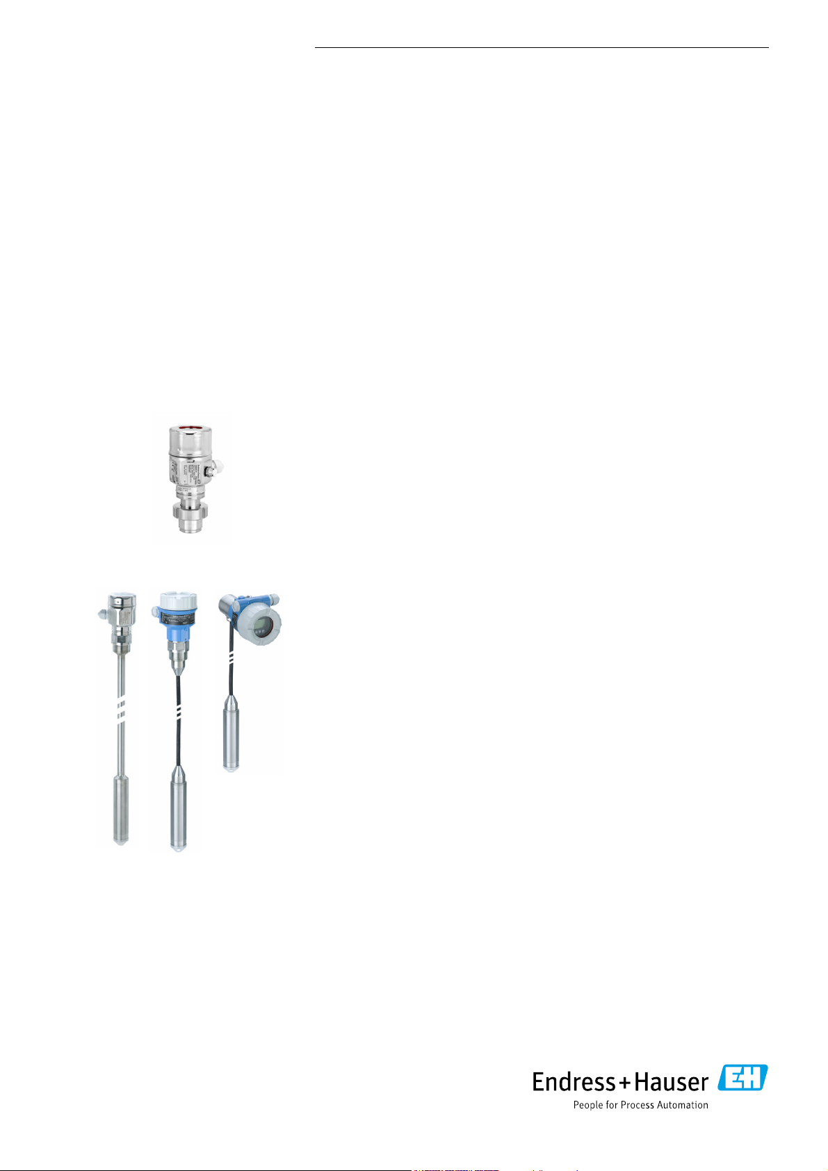
Hydrostatic level measurement
Pressure sensor with the CONTITETM measuring cell
Condensate-resistant
Application
The device is used for the following measuring tasks:
• Hydrostatic pressure measurement in liquids and paste-like media in all areas of
process engineering, process measuring technology, pharmaceuticals and the food
industry
• Level, volume or mass measurements in liquids
Your benefits
• Very good reproducibility and long-term stability
• Maximum plant safety provided by one-of-a-kind, condensate-proofed CONTITE
measuring cell
• High reference accuracy: ±0.2 %
optionally ±0.1 %
• Turn down 100:1
• Standardized platform for differential pressure, hydrostatics, and pressure
(Deltabar M – Deltapilot M – Cerabar M)
• Simple, fast commissioning through a user interface designed for real-world
applications
• Used for process pressure monitoring up to SIL2, certified to IEC 61508 Edition 2.0
and IEC 61511 by TÜV NORD
• Usage in drinking water: KTW, NSF
Page 2

Table of contents
Deltapilot M FMB50/51/52/53
Document information . . . . . . . . . . . . . . . . . . . . . . . . . . .4
Symbols used . . . . . . . . . . . . . . . . . . . . . . . . . . . . . . . . . . . . . . . . . 4
Terms and abbreviations . . . . . . . . . . . . . . . . . . . . . . . . . . . . . . . 6
Turn down calculation . . . . . . . . . . . . . . . . . . . . . . . . . . . . . . . . . 7
Function and system design . . . . . . . . . . . . . . . . . . . . . .8
Device selection . . . . . . . . . . . . . . . . . . . . . . . . . . . . . . . . . . . . . . . 8
Measuring principle . . . . . . . . . . . . . . . . . . . . . . . . . . . . . . . . . . 10
Level measurement in closed tanks with pressure overlay . . 11
Density measurement . . . . . . . . . . . . . . . . . . . . . . . . . . . . . . . . . 12
Level measurement with automatic density correction (with
media changing in the tank) . . . . . . . . . . . . . . . . . . . . . . . . . . . 12
Electrical differential pressure measurement with gauge
pressure sensors . . . . . . . . . . . . . . . . . . . . . . . . . . . . . . . . . . . . . 13
Communication and data processing . . . . . . . . . . . . . . . . . . . . 13
Input . . . . . . . . . . . . . . . . . . . . . . . . . . . . . . . . . . . . . . . . 14
Measured variable . . . . . . . . . . . . . . . . . . . . . . . . . . . . . . . . . . . . 14
Measuring range . . . . . . . . . . . . . . . . . . . . . . . . . . . . . . . . . . . . . 14
Output . . . . . . . . . . . . . . . . . . . . . . . . . . . . . . . . . . . . . . . 15
Output signal . . . . . . . . . . . . . . . . . . . . . . . . . . . . . . . . . . . . . . . . 15
Signal range – 4 to 20 mA HART . . . . . . . . . . . . . . . . . . . . . . . 15
Signal on alarm . . . . . . . . . . . . . . . . . . . . . . . . . . . . . . . . . . . . . . 15
Load - 4 to 20 mA HART . . . . . . . . . . . . . . . . . . . . . . . . . . . . . . 15
Dead time, time constant . . . . . . . . . . . . . . . . . . . . . . . . . . . . . . 16
Dynamic behavior: current output . . . . . . . . . . . . . . . . . . . . . . . 16
Dynamic behavior: HART . . . . . . . . . . . . . . . . . . . . . . . . . . . . . . 16
Dynamic behavior: PROFIBUS PA . . . . . . . . . . . . . . . . . . . . . . . 17
Dynamic behavior: FOUNDATION Fieldbus . . . . . . . . . . . . . . . 17
Damping . . . . . . . . . . . . . . . . . . . . . . . . . . . . . . . . . . . . . . . . . . . . 17
Firmware version . . . . . . . . . . . . . . . . . . . . . . . . . . . . . . . . . . . . . 17
Galvanic isolation . . . . . . . . . . . . . . . . . . . . . . . . . . . . . . . . . . . . 18
Protocol-specific data . . . . . . . . . . . . . . . . . . . . . . . . . . . . . . . . . 18
Power supply . . . . . . . . . . . . . . . . . . . . . . . . . . . . . . . . . 22
Terminal assignment . . . . . . . . . . . . . . . . . . . . . . . . . . . . . . . . . 22
Supply voltage . . . . . . . . . . . . . . . . . . . . . . . . . . . . . . . . . . . . . . . 22
Current consumption . . . . . . . . . . . . . . . . . . . . . . . . . . . . . . . . . 23
Electrical connection . . . . . . . . . . . . . . . . . . . . . . . . . . . . . . . . . . 23
Terminals . . . . . . . . . . . . . . . . . . . . . . . . . . . . . . . . . . . . . . . . . . . 23
Cable entry . . . . . . . . . . . . . . . . . . . . . . . . . . . . . . . . . . . . . . . . . . 23
Connector . . . . . . . . . . . . . . . . . . . . . . . . . . . . . . . . . . . . . . . . . . . 24
Cable specification . . . . . . . . . . . . . . . . . . . . . . . . . . . . . . . . . . . . 25
Start-up current HART. . . . . . . . . . . . . . . . . . . . . . . . . . . . . . . . 25
Residual ripple . . . . . . . . . . . . . . . . . . . . . . . . . . . . . . . . . . . . . . . 25
Influence of power supply . . . . . . . . . . . . . . . . . . . . . . . . . . . . . . 25
Overvoltage protection (optional) . . . . . . . . . . . . . . . . . . . . . . . 26
Performance characteristics . . . . . . . . . . . . . . . . . . . . 27
Reference operating conditions . . . . . . . . . . . . . . . . . . . . . . . . . 27
Influence of orientation . . . . . . . . . . . . . . . . . . . . . . . . . . . . . . . 27
Calibration position . . . . . . . . . . . . . . . . . . . . . . . . . . . . . . . . . . . 27
Resolution . . . . . . . . . . . . . . . . . . . . . . . . . . . . . . . . . . . . . . . . . . . 27
Reference accuracy . . . . . . . . . . . . . . . . . . . . . . . . . . . . . . . . . . . 27
Thermal change in the zero output and the output span . . . . 28
Total performance . . . . . . . . . . . . . . . . . . . . . . . . . . . . . . . . . . . . 28
Long-term stability . . . . . . . . . . . . . . . . . . . . . . . . . . . . . . . . . . . 28
Total error . . . . . . . . . . . . . . . . . . . . . . . . . . . . . . . . . . . . . . . . . . 28
Warm-up period . . . . . . . . . . . . . . . . . . . . . . . . . . . . . . . . . . . . . 28
Installation . . . . . . . . . . . . . . . . . . . . . . . . . . . . . . . . . . . 29
General installation instructions . . . . . . . . . . . . . . . . . . . . . . . . 29
FMB50 . . . . . . . . . . . . . . . . . . . . . . . . . . . . . . . . . . . . . . . . . . . . . 29
FMB51/FMB52/FMB53 . . . . . . . . . . . . . . . . . . . . . . . . . . . . . . 29
Supplementary installation instructions . . . . . . . . . . . . . . . . . . 30
Wall and pipe mounting . . . . . . . . . . . . . . . . . . . . . . . . . . . . . . . 30
"Separate housing" version . . . . . . . . . . . . . . . . . . . . . . . . . . . . . 31
Oxygen applications . . . . . . . . . . . . . . . . . . . . . . . . . . . . . . . . . . 32
PWIS cleaning . . . . . . . . . . . . . . . . . . . . . . . . . . . . . . . . . . . . . . . 32
Applications with hydrogen . . . . . . . . . . . . . . . . . . . . . . . . . . . . 32
Special measuring cells for acids, alkalis or sea water
(not FMB50) . . . . . . . . . . . . . . . . . . . . . . . . . . . . . . . . . . . . . . . . 32
Environment . . . . . . . . . . . . . . . . . . . . . . . . . . . . . . . . . 33
Ambient temperature limits . . . . . . . . . . . . . . . . . . . . . . . . . . . 33
Storage temperature range . . . . . . . . . . . . . . . . . . . . . . . . . . . . 33
Climate class . . . . . . . . . . . . . . . . . . . . . . . . . . . . . . . . . . . . . . . . . 33
Degree of protection . . . . . . . . . . . . . . . . . . . . . . . . . . . . . . . . . . 33
Vibration resistance . . . . . . . . . . . . . . . . . . . . . . . . . . . . . . . . . . 33
Electromagnetic compatibility . . . . . . . . . . . . . . . . . . . . . . . . . . 34
Process . . . . . . . . . . . . . . . . . . . . . . . . . . . . . . . . . . . . . . 35
Process temperature range . . . . . . . . . . . . . . . . . . . . . . . . . . . . 35
Lateral load FMB51 (static) . . . . . . . . . . . . . . . . . . . . . . . . . . . 35
Pressure specifications . . . . . . . . . . . . . . . . . . . . . . . . . . . . . . . . 35
Mechanical construction . . . . . . . . . . . . . . . . . . . . . . . 36
Device height . . . . . . . . . . . . . . . . . . . . . . . . . . . . . . . . . . . . . . . . 36
F31 housing, aluminum . . . . . . . . . . . . . . . . . . . . . . . . . . . . . . . 36
F15 housing, stainless steel (hygienic) . . . . . . . . . . . . . . . . . . . 37
Diameter of the process isolating diaphragm . . . . . . . . . . . . . 37
Process connections FMB50, FMB51, FMB52 . . . . . . . . . . . . 37
Process connections FMB50, FMB51, FMB52 . . . . . . . . . . . . 38
Process connections FMB50, FMB51, FMB52 - continued . . 39
Process connections FMB50, FMB51, FMB52 - continued . . 40
Process connections FMB50 - continued . . . . . . . . . . . . . . . . . 41
Process connections FMB50 - continued . . . . . . . . . . . . . . . . 42
Process connections FMB51 (rod version) . . . . . . . . . . . . . . . . 44
Process connections FMB52 (cable version) . . . . . . . . . . . . . . 46
Dimensions of FMB53 with F31 housing, suspension clamp and
mounting bracket . . . . . . . . . . . . . . . . . . . . . . . . . . . . . . . . . . . . 48
Dimensions of FMB53 with F15 housing, suspension clamp and
mounting bracket . . . . . . . . . . . . . . . . . . . . . . . . . . . . . . . . . . . . 49
Wall and pipe mounting with "Separate housing" version . . . 50
Materials not in contact with process . . . . . . . . . . . . . . . . . . . . 53
Materials in contact with the process . . . . . . . . . . . . . . . . . . . . 56
Operability . . . . . . . . . . . . . . . . . . . . . . . . . . . . . . . . . . . 59
Operating concept . . . . . . . . . . . . . . . . . . . . . . . . . . . . . . . . . . . . 59
Onsite operation . . . . . . . . . . . . . . . . . . . . . . . . . . . . . . . . . . . . . 59
Operating languages . . . . . . . . . . . . . . . . . . . . . . . . . . . . . . . . . . 61
Remote operation . . . . . . . . . . . . . . . . . . . . . . . . . . . . . . . . . . . . 61
System integration . . . . . . . . . . . . . . . . . . . . . . . . . . . . . . . . . . . 62
2 Endress+Hauser
Page 3

Certificates and approvals . . . . . . . . . . . . . . . . . . . . . . 63
CE mark . . . . . . . . . . . . . . . . . . . . . . . . . . . . . . . . . . . . . . . . . . . . . 63
RCM-Tick marking . . . . . . . . . . . . . . . . . . . . . . . . . . . . . . . . . . . . 63
Ex approvals . . . . . . . . . . . . . . . . . . . . . . . . . . . . . . . . . . . . . . . . . 63
EAC conformity . . . . . . . . . . . . . . . . . . . . . . . . . . . . . . . . . . . . . . 63
Suitability for hygienic processes . . . . . . . . . . . . . . . . . . . . . . . . 63
Certificate of Compliance ASME BPE 2012 (FMB50 only) . . 64
Functional safety SIL . . . . . . . . . . . . . . . . . . . . . . . . . . . . . . . . . . 64
Overfill protection . . . . . . . . . . . . . . . . . . . . . . . . . . . . . . . . . . . . 64
AD2000 . . . . . . . . . . . . . . . . . . . . . . . . . . . . . . . . . . . . . . . . . . . . . 64
Pressure Equipment Directive (PED) . . . . . . . . . . . . . . . . . . . . . 64
Manufacturer declaration . . . . . . . . . . . . . . . . . . . . . . . . . . . . . . 64
Marine approval . . . . . . . . . . . . . . . . . . . . . . . . . . . . . . . . . . . . . . 64
Other standards and guidelines . . . . . . . . . . . . . . . . . . . . . . . . . 65
Drinking water approval . . . . . . . . . . . . . . . . . . . . . . . . . . . . . . . 65
Classification of process sealing between electrical systems and
(flammable or combustible) process fluids in accordance with
ANSI/ISA 12.27.01 . . . . . . . . . . . . . . . . . . . . . . . . . . . . . . . . . . . 65
Inspection certificate . . . . . . . . . . . . . . . . . . . . . . . . . . . . . . . . . . 65
Calibration; unit . . . . . . . . . . . . . . . . . . . . . . . . . . . . . . . . . . . . . . 66
Calibration . . . . . . . . . . . . . . . . . . . . . . . . . . . . . . . . . . . . . . . . . . . 66
Service . . . . . . . . . . . . . . . . . . . . . . . . . . . . . . . . . . . . . . . . . . . . . . 66
Deltapilot M FMB50/51/52/53
Ordering information . . . . . . . . . . . . . . . . . . . . . . . . . . 67
Configuration data sheet . . . . . . . . . . . . . . . . . . . . . . . . . . . . . . . 67
Accessories . . . . . . . . . . . . . . . . . . . . . . . . . . . . . . . . . . . 69
Suspension clamp (FMB53 only) . . . . . . . . . . . . . . . . . . . . . . . . 69
Extension cable shortening kit (FMB53 only) . . . . . . . . . . . . . 69
M12 connector . . . . . . . . . . . . . . . . . . . . . . . . . . . . . . . . . . . . . . . 69
Welding necks and Weld-in tool flanges . . . . . . . . . . . . . . . . . 69
Adapter Uni for FMB50 . . . . . . . . . . . . . . . . . . . . . . . . . . . . . . . 70
Documentation. . . . . . . . . . . . . . . . . . . . . . . . . . . . . . . . 71
Technical Information . . . . . . . . . . . . . . . . . . . . . . . . . . . . . . . . . 71
Operating Instructions . . . . . . . . . . . . . . . . . . . . . . . . . . . . . . . . . 71
Brief Operating Instructions . . . . . . . . . . . . . . . . . . . . . . . . . . . . 71
Functional safety manual (SIL) . . . . . . . . . . . . . . . . . . . . . . . . . 71
Safety Instructions . . . . . . . . . . . . . . . . . . . . . . . . . . . . . . . . . . . . 71
Installation/Control Drawings . . . . . . . . . . . . . . . . . . . . . . . . . . 72
Combination certificate . . . . . . . . . . . . . . . . . . . . . . . . . . . . . . . . 72
Overfill protection . . . . . . . . . . . . . . . . . . . . . . . . . . . . . . . . . . . . 72
Registered trademarks . . . . . . . . . . . . . . . . . . . . . . . . . 73
HART® . . . . . . . . . . . . . . . . . . . . . . . . . . . . . . . . . . . . . . . . . . . . . . 73
PROFIBUS® . . . . . . . . . . . . . . . . . . . . . . . . . . . . . . . . . . . . . . . . . . 73
FOUNDATION™ Fieldbus . . . . . . . . . . . . . . . . . . . . . . . . . . . . . . 73
3 Endress+Hauser
Page 4
Document information
DANGER
WARNING
CAUTION
NOTICE
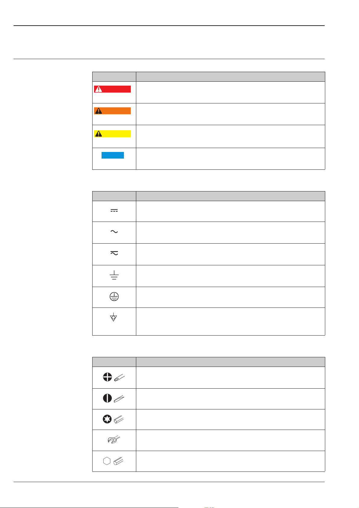
Symbols used Safety symbols
Symbol Meaning
A0011189-EN
A0011190-EN
A0011191-EN
A0011192-EN
Electrical symbols
Deltapilot M FMB50/51/52/53
DANGER!
This symbol alerts you to a dangerous situation. Failure to avoid this situation will result in
serious or fatal injury.
WARNING!
This symbol alerts you to a dangerous situation. Failure to avoid this situation can result in
serious or fatal injury.
CAUTION!
This symbol alerts you to a dangerous situation. Failure to avoid this situation can result in
minor or medium injury.
NOTE!
This symbol contains information on procedures and other facts which do not result in
personal injury.
Symbol Meaning
Direct current
A terminal at which DC voltage is present or through which direct current flows.
A0018335
Alternating current
A terminal at which alternating voltage is present or through which alternating current
A0018336
flows.
Direct current and alternating current
• A terminal at which alternating voltage or DC voltage is present.
A0018337
• A terminal through which alternating current or direct current flows.
Ground connection
A grounded terminal which, as far as the operator is concerned, is grounded via a
A0018338
grounding system.
Protective ground connection
A terminal which must be connected to ground prior to establishing any other connections.
A0018339
Equipotential connection
A connection that has to be connected to the plant grounding system: This may be a
A0011201
potential equalization line or a star grounding system depending on national or company
codes of practice.
Tool symbols
Symbol Meaning
Phillips head screwdriver
A0011219
Flat-blade screwdriver
A0011220
Torx screwdriver
A0013442
Hexagon wrench
A0011222
Allen screw
A0011221
4 Endress+Hauser
Page 5
Deltapilot M FMB50/51/52/53
1.
2.
1.
2.
-
.
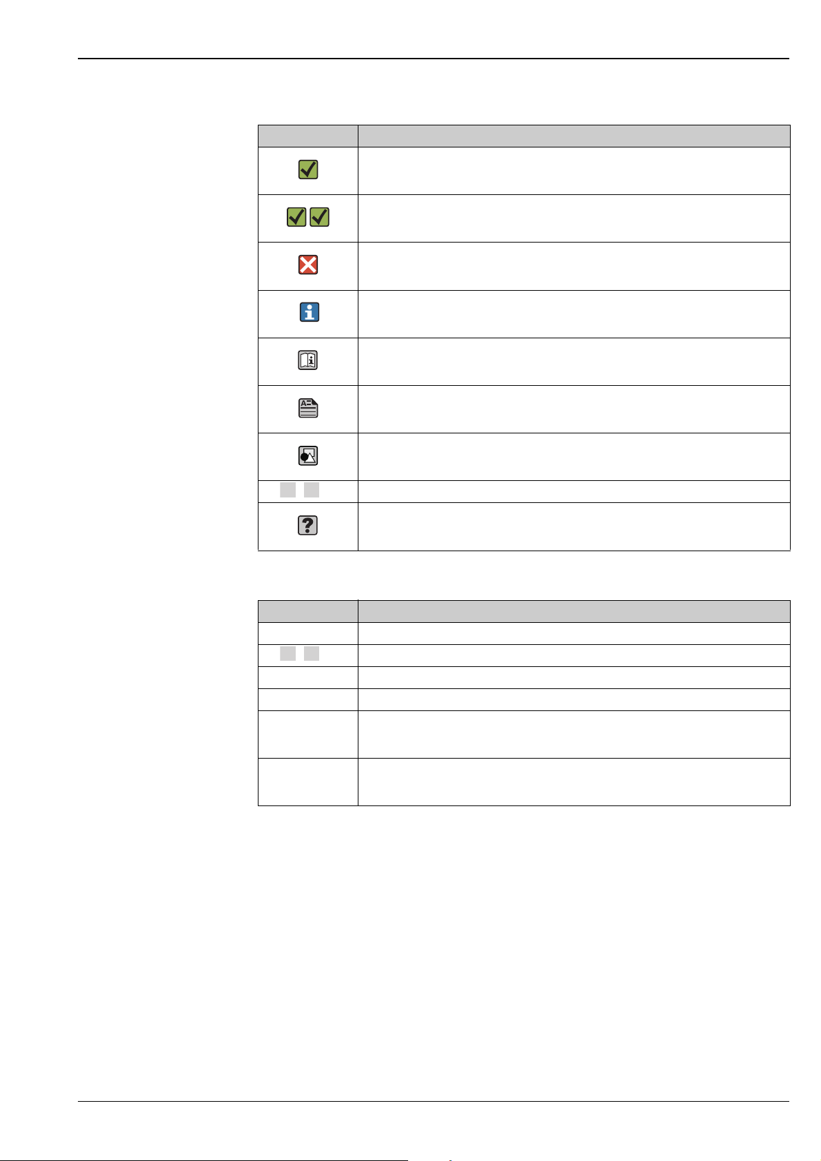
Symbols for certain types of information
Symbol Meaning
Permitted
Indicates procedures, processes or actions that are permitted.
A0011182
Preferred
Indicates procedures, processes or actions that are preferred.
A0011183
Forbidden
Indicates procedures, processes or actions that are forbidden.
A0011184
Tip
Indicates additional information.
A0011193
Reference to documentation
Refers to the corresponding device documentation.
A0015483
Reference to page
Refers to the corresponding page number.
A0015484
Reference to graphics
Refers to the corresponding graphic number and page number.
A0015486
, , ... Series of steps
Help in the event of a problem
A0015488
Symbols in graphics
Symbol Meaning
1, 2, 3, 4 etc. Numbering for main items
, , ... Series of steps
A, B, C, D etc. Views
A-A, B-B, etc. Sections
Hazardous area
Indicates the hazardous area.
A0011187
Safe area (non-hazardous area)
Indicates the non-hazardous area.
A0011188
Endress+Hauser 5
Page 6
Terms and abbreviations
URL OPLMWP
LRL
0
p
LRV
URV
1
2
3
4
Deltapilot M FMB50/51/52/53
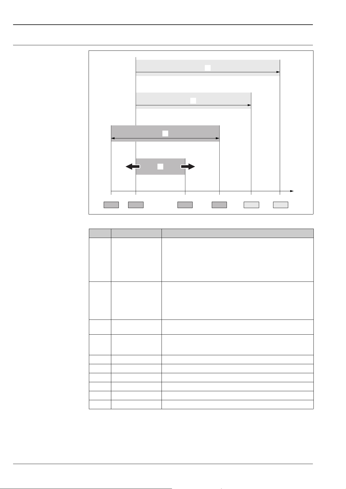
Position Term/Abbreviation Explanation
1 OPL The OPL (over pressure limit = sensor overload limit) for the sensors
depends on the lowest-rated element, with regard to pressure, of the
selected components, i.e. the process connection must be taken into
consideration in addition to the measuring cell. Also observe pressuretemperature dependency. For the relevant standards and additional notes,
see the " ä 35" section.
The OPL may be applied for a limited time period.
2 MWP The MWP (maximum working pressure) for the sensors depends on the
lowest-rated element, with regard to pressure, of the selected components,
i.e. the process connection has to be taken into consideration in addition to
the measuring cell. Also observe pressure-temperature dependency. For the
relevant standards and additional notes, see the " ä 35" section.
The MWP may be applied for an unlimited time.
3Maximum sensor
4 Calibrated/Adjusted
p - Pressure
- LRL Lower range limit
-URL Upper range limit
- LRV Lower range value
-URV Upper range value
-TD Turn down
measuring range
measuring span
Range between LRL and URL
This span is the maximum calibratable/adjustable measuring span.
Range between LRV and URV
Factory setting: 0...URL
Other calibrated spans can be ordered with customised settings.
A0029505
6 Endress+Hauser
Page 7

Deltapilot M FMB50/51/52/53
LRV
URLURV
LRL
1 = 2
3
Turn down calculation
1 Calibrated/Adjusted measuring span
2 Zero-based span
3 Upper range limit
Example
• Sensor: 10 bar (150 psi)
• Upper range limit (URL) = 10 bar (150 psi)
Turn down (TD):
TD =
|URV - LRV|
URL
A0029545
• Calibrated/Adjusted measuring span: 0...5 bar
(0...75 psi)
• Lower range value (LRV) = 0 bar
• Upper range value (URV) = 5 bar (75 psi)
TD =
In this example, the TD is thus 2:1.
This span is based on the zero point.
|5 bar (75 psi) - 0 bar (0 psi)|
10 bar (150 psi)
=2
Endress+Hauser 7
Page 8
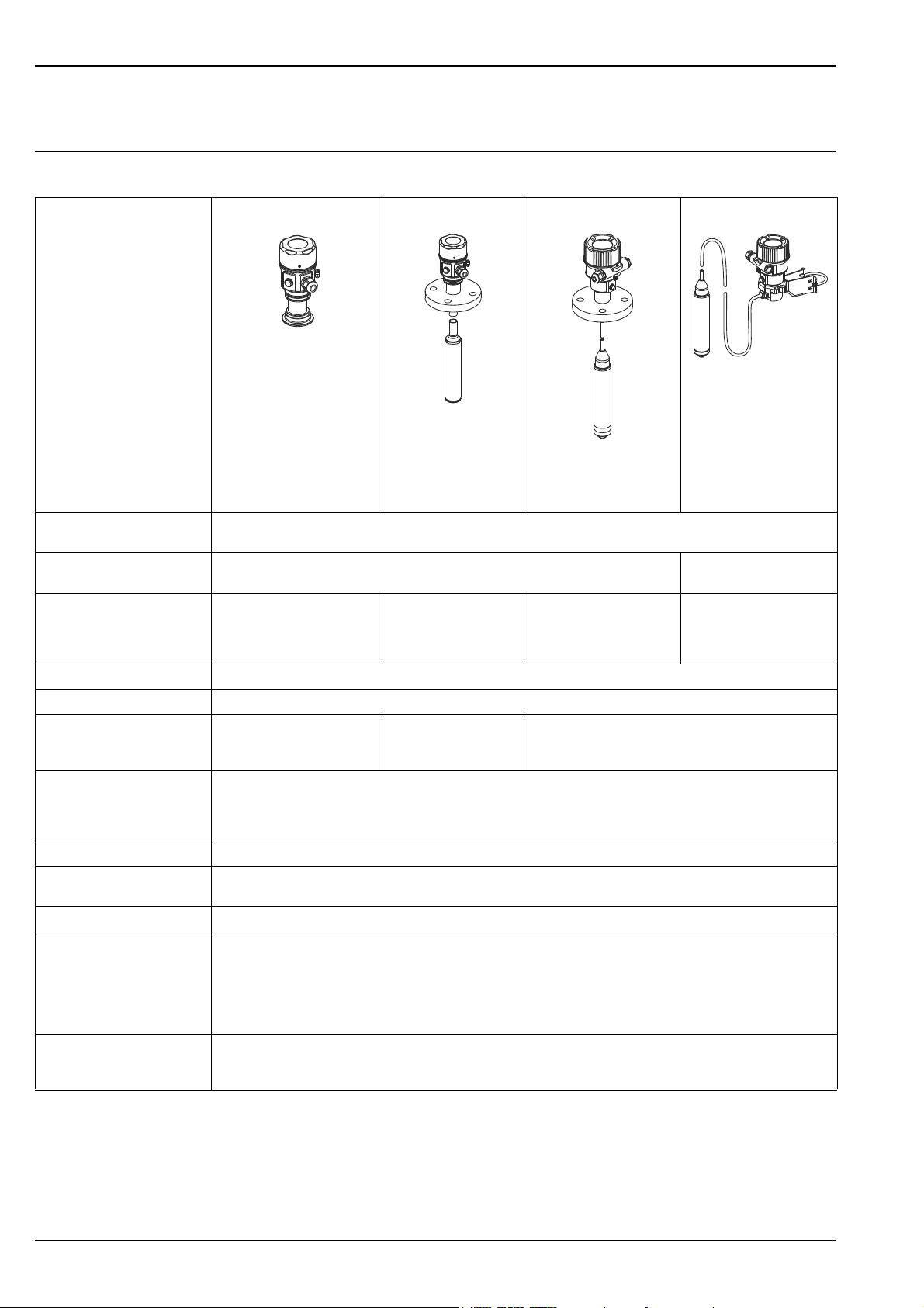
Device selection
Deltapilot M FMB50/51/52/53
Function and system design
Deltapilot M –
FMB50
FMB51
FMB52
FMB53
Product family
Compact version
A0023537
Rod version
A0023538
Cable version
A0023539
Cable version with
A0023540
Mounting bracket
Field of application – Level measurement
– Pressure measurement
Industries Food, pharmaceuticals, chemicals, power plants, automotive, etc. Environment (freshwater
and wastewater)
Process connections – Thread
–Flanges
–Thread
–Flanges
–Thread
–Flanges
Suspension clamp
– Flush-mounted hygienic
connections
Measuring ranges From –0.1 to +0.1 (-1.5 to +1.5 psi) bar to –1 bar to +10 bar (-15 to 150 psi)
OPL Max. 40 bar (600 psi)
Process temperature range –10 to +100 °C (+14 to
+212°F) (+135 °C (275°F) for
30 minutes maximum)
–10 to +85 °C
(+14 to +185°F)
With PE cable (unmoved): –10 to +70 °C (+14 to +158°F)
With FEP cable (unmoved):
–10 to +80 °C (+14 to +176°F)
Ambient temperature range • Without LCD display: -40 to +85 °C (-40 to +185°F)
• With LCD display: -20 to +70 °C (-4 to +158°F) (extended temperature application range -40 to 85 °C
(-40 to +158°F) with restrictions in optical properties such as display speed and contrast)
• Separate housing: -20 to +60 °C (-4 to +140°F)
Reference accuracy 0.2 % (option 0.1 %) depends on the measuring range ä 27
Supply voltage – 11.5 to 45 V DC (versions with plug-in connection 35 V DC)
– For intrinsically safe device versions: 11.5 to 30 V DC
Output 4 to 20 mA with superimposed HART protocol, PROFIBUS PA or FOUNDATION Fieldbus
Options – Gold/rhodium-coated process isolating diaphragm
– 3.1 inspection certificate
– 3A approval and EHEDG approval for FMB50
– Specific firmware versions
– Initial device settings can be ordered
– Separate housing
Specialties – Absolute resistance to condensate thanks to hermetically sealed CONTITE
TM
cell
– Maximum flexibility thanks to modular design
– Special cleaning of the transmitter to remove paint-wetting substances, for use in paint shops
8 Endress+Hauser
Page 9
Deltapilot M FMB50/51/52/53
TYPE EL
February 2010
74 -
FMB50, FMB51, FMB52 universal application
• Modular probe program to ensure optimum process adaptation
• FMB50 compact version: installation in the tank from below or from the side
• FMB51, FMB52 rod and cable extension: installation from above, i.e. easy to retrofit ground tanks,
no additional opening in the vessel floor
FMB50 optimized for hygienic applications
• All typical flush-mounted process connections can be supplied
• Welding flanges
• Stainless steel housing
• All the sanitary process connections are gap-free and can be cleaned so that the unit is free of
residue, e.g. CIP cleaning
• USDA/H1-approved transfer liquid as per FDA Directive
• 3A approval or EHEDG approvals
A0023536
A0020029
FMB53 for level measurement in water and wastewater
• The housing with the electronic insert is mounted outside shafts and vessels in such a way that it is
protected from flooding. The extension cable is secured with a suspension clamp.
• The measuring cell tube made of stainless steel (AISI 316L) and the Alloy process isolating
diaphragm allow use in aggressive media such as wastewater for example.
• Extension cable up to 400 m (1312 ft) in length (up to 100 m (328 ft) in Ex-areas) without strain
relief.
• Special measuring cell with gold/rhodium coating for applications in which severe hydrogen
formation can occur (e.g. digested sludge); ä 32.
• Special measuring cell with gold/platinum coating for acids, alkalis or sea water; ä 32.
Endress+Hauser 9
Page 10

Measuring principle
h
h =
p
r · g
p = p - p
mess ges atm
p = (p + p
mess atm hydr.
) - p
atm
3
2
1
p
atm
p
atm
p
ges
p
hydr.
h ~ p
p
atm
p= p + p
atm hydr.
p = p + p
ges atm hydr.
Deltapilot M FMB50/51/52/53
A0023541
Deltapilot M hydrostatic level measurement and measuring principle
1 Rear isolating membrane of the CONTITE™ measuring cell
2 Measuring element
3 Process isolating diaphragm
g Gravitational acceleration
h Level height
Total pressure = hydrostatic pressure + atmospheric pressure
p
ges
Atmospheric pressure
p
atm
Hydrostatic pressure
p
hydr.
Measured pressure in the measuring cell = hydrostatic pressure
p
mess
Density of the medium
Due to its weight, a liquid column creates hydrostatic pressure. If the density is constant, the
hydrostatic pressure depends solely on the height h of the liquid column.
The CONTITE™ measuring cell, which works on the principle of the gauge pressure sensor, constitutes
the core of Deltapilot M. In contrast to conventional gauge pressure sensors, the precision measuring
element (2) in the CONTITE™ measuring cell is absolutely protected, situated between the process
isolating diaphragm (3) and the rear isolating membrane (1). Thanks to this hermetic sealing of the
measuring element, the CONTITE™ measuring cell is absolutely insensitive to condensate/
condensation and aggressive gases. The pressure applied is transferred from the process isolating
diaphragm to the measuring element by means of an oil without any loss in pressure.
Any measured errors due to fluctuations in temperature are compensated for in the electronics unit by
means of the sensor temperature.
A linearization function with max. 32 points, based on a table entered either manually or
semi-automatically, can be activated locally or remotely. This function facilitates measurement in
engineering units, and provides a linear output signal for spherical and horizontal cylindrical vessels,
and vessels with a conical outlet.
10 Endress+Hauser
Page 11
Deltapilot M FMB50/51/52/53
NOTICE
NOTICE
1
2
3
Level measurement in closed tanks with pressure overlay
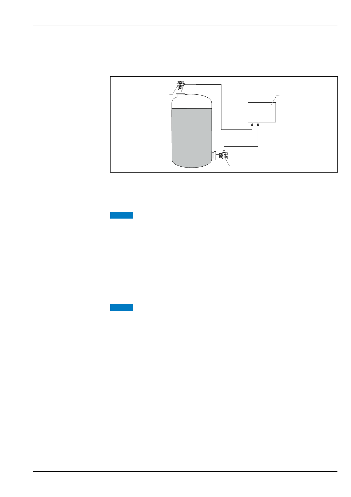
You can determine the differential pressure in tanks with pressure overlay using two Deltapilot M. The
pressure measured values of the two probes are sent to a signal processing unit such as
Endress+Hauser RMA or a PLC. The signal processing unit or PLC determines the difference in pressure
and uses this to calculate the level and the density where necessary.
A0023542
Level measurement in a closed tank with pressure overlay
1 Deltapilot 1 measures the total pressure (hydrostatic pressure and top pressure)
2 Deltapilot 2 measures the top pressure
3 Signal processing unit determines the difference in pressure and uses this to calculate the level
Measured errors can occur.
Large measured errors can occur if the ratio of the level to the top pressure is >1:6. This does not affect
reproducibility.
‣ When selecting the measuring cell, make sure you select measuring ranges that are sufficiently
wide ( see example).
Example:
• Max. hydrostatic pressure = 600 mbar (9 psi)
• Max. top pressure (Deltapilot 2) = 300 mbar (4.5 psi)
• Max. total pressure, measured with Deltapilot 1 = 300 mbar (4.5 psi) + 600 mbar (9 psi) = 900 mbar
(13.5 psi) measuring cell to be selected: 0 to 1200 mbar (0 to 18 psi)
• Max. pressure, measured with Deltapilot 2: 300 mbar (4.5 psi) measuring cell to be selected:
0 to 400 mbar (6 psi)
Possibility of probe 2 flooding during differential pressure measurement.
Measured errors can occur.
‣ When installing, make sure that probe 2 cannot be flooded.
Endress+Hauser 11
Page 12
Deltapilot M FMB50/51/52/53
p
2
Δh
p
1
1
2
3
Δh
1
2
3
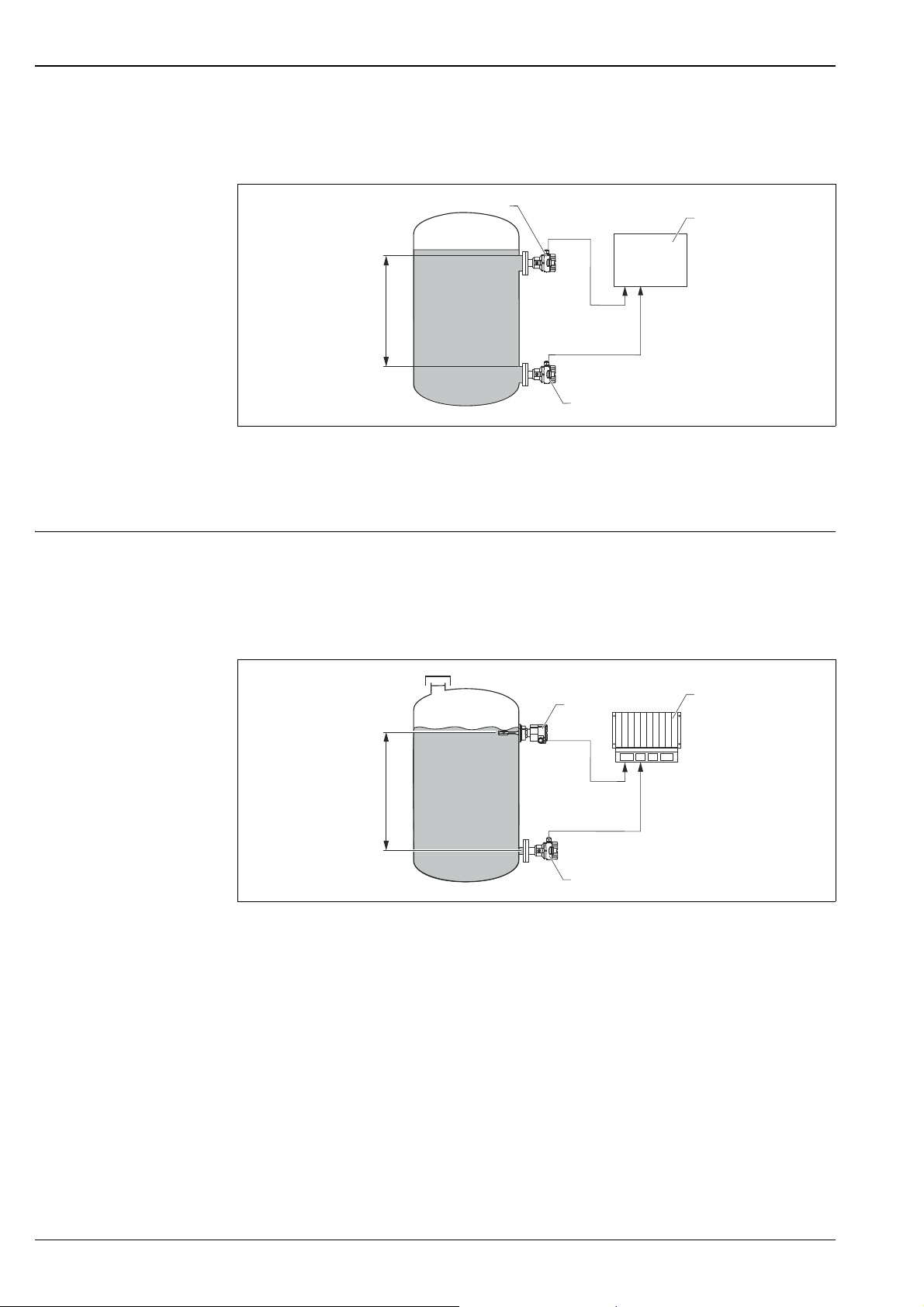
Density measurement You can measure the density in tanks with pressure overlay using two Deltapilot M and a signal
processing unit or a PLC. The signal processing unit or the PLC calculates the density from the known
distance between the two Deltapilot M devices h and the two measured values p
Level measurement in a closed tank with pressure overlay
1 Deltapilot 1 determines pressure measured value p
2 Deltapilot 2 determines pressure measured value p
3 Signal processing unit determines the density from the two measured values p1 and p2 and the distance h
1
2
and p2.
1
A0023544
Level measurement with automatic density correction (with media changing in the tank)
Level measurement with automatic density correction is possible in conjunction with a limit switch
such as Liquiphant and a PLC. The limit switch always switches at the same level. In the switch point,
the signal processing unit determines the corrected density from the pressure of the Deltapilot M
currently measured and the known distance between Deltapilot M and the limit switch. The signal
processing unit then calculates the level from the new density and the measured pressure of the
Deltapilot M.
A0023546
Level measurement with automatic density correction
1 Deltapilot M
2Liquiphant
3PLC
12 Endress+Hauser
Page 13
Deltapilot M FMB50/51/52/53
WARNING
!
Fieldgate
FXA520
FXN 520
FXN 520
Multidrop-Connector
FXN520
Deltapilot M
Á
11
2
Electrical differential pressure measurement with gauge pressure sensors
A0023549
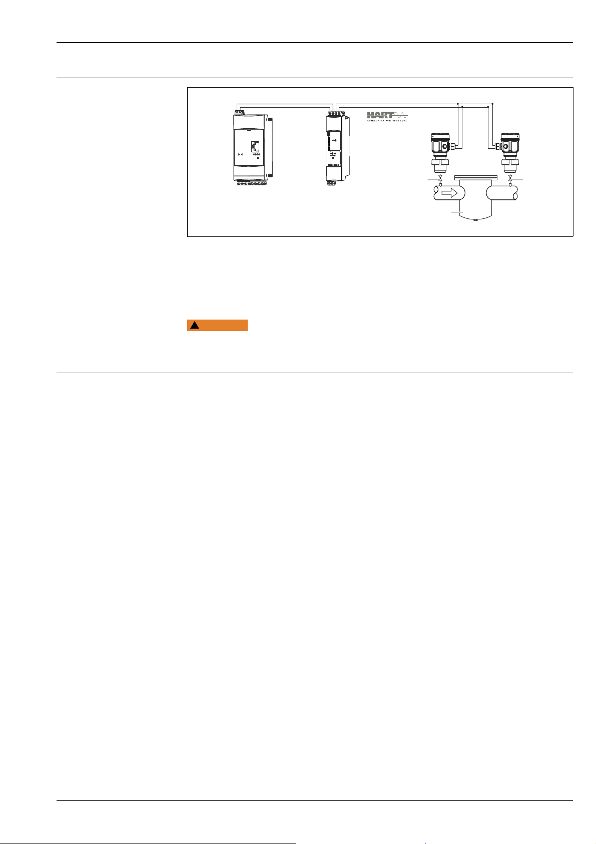
1 Shut-off valves
2 e.g. filter
In the example given, two Deltapilot M devices (each with a gauge pressure sensor) are interconnected.
The pressure difference can thus be measured using two independent Deltapilot M devices.
Communication and data processing
Risk of explosion!
‣ If using intrinsically safe devices, strict compliance with the rules for interconnecting intrinsically
safe circuits as stipulated in IEC60079-14 (proof of intrinsic safety) is mandatory.
• 4 to 20 mA with HART communication protocol
•PROFIBUS PA
– The Endress+Hauser devices meet the requirements of the FISCO model.
– Due to the low current consumption of 11 mA ± 1 mA, the following number of devices can be
operated on one bus segment if installing as per FISCO:
– up to 8 Deltapilot M for Ex ia, CSA IS and FM IS applications
– up to 31 Deltapilot M for all other applications, e.g. in non-hazardous areas, Ex nA, etc.
Further information on PROFIBUS PA can be found in Operating Instructions BA00034S "PROFIBUS
DP/PA: Guidelines for planning and commissioning" and in the PNO Guideline.
• FOUNDATION Fieldbus
– The Endress+Hauser devices meet the requirements of the FISCO model.
– Due to the low current consumption of 16 mA ± 1 mA, the following number of devices can be
operated on one bus segment if installing as per FISCO:
– up to 6 Deltapilot M for Ex ia, CSA IS and FM IS applications
– up to 22 Deltapilot M for all other applications, e.g. in non-hazardous areas, Ex nA, etc.
Further information on FOUNDATION Fieldbus, such as requirements for bus system components
can be found in Operating Instructions BA00013S "FOUNDATION Fieldbus Overview".
Endress+Hauser 13
Page 14
Input
Measured variable Hydrostatic pressure
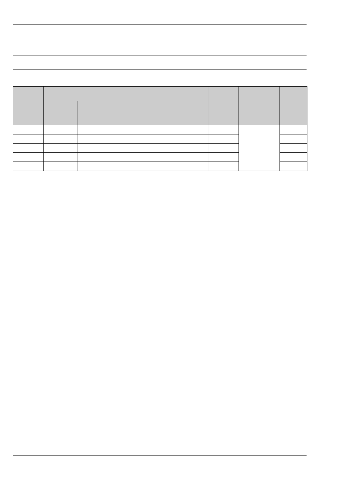
Measuring range
Deltapilot M FMB50/51/52/53
Sensor Maximum sensor measuring
range
lower (LRL) 4) upper (URL) Synthetic oil/
[bar (psi)] [bar (psi)] [bar (psi)] [bar (psi)] [bar (psi)] [bar (psi)] [bar
0.1 (1.5) –0.1 (-1.5) +0.1 (+1.5) 0.01 (0.15) 2.7 (40.5) 4 (60) 0.01/0.04
0.4 (6) –0.4 (-6) +0.4 (+6) 0.02 (0.3) 5.3 (79.5) 8 (120) 1F
1.2 (18) –1 (-15) +1.2 (+18) 0.06 (1) 16 (240) 24 (360) 1H
4 (60) –1 (-15) +4 (+60) 0.2 (3) 16 (240) 24 (360) 1M
10 (150) –1 (-15) +10 (+150) 0.5 (7.5) 27 (405) 40 (600) 1P
1) Factory calibration Turn down: Max 20:1, higher on request.
2) The vacuum resistance applies to the measuring cell at reference conditions.
3) Product Configurator, "Sensor range" ordering feature
4) By default, the device is set to a lower range limit of 0 bar. Please specify in the order if the lower range limit is to be set to a different default value.
Smallest calibratable
measuring span
(preset at the factory)
MWP OPL Vacuum
1)
resistance
Inert oil
(0.145/0.6)
abs
(psi
2)
)]
abs
Option
1C
3)
14 Endress+Hauser
Page 15
Deltapilot M FMB50/51/52/53
U – 11.5 V
23 mA
[]W
30
20
11.5
40 45
1239
1456
804
369
£
U
[V]
1
2
R
L
max
3
R
L
max
Output
Output signal • 4 to 20 mA with superimposed digital communication protocol HART 6.0, 2-wire
• Digital communication signal PROFIBUS PA (Profile 3.02)
• Digital communication signal FOUNDATION Fieldbus
Output Option 1)
4 to 20mA HART 2
PROFIBUS PA 3
FOUNDATION Fieldbus 4
1) Product Configurator, "Output" ordering feature
Signal range –
3.8 to 20.5 mA
4to20mAHART
Signal on alarm As per NAMUR NE 43
• 4 to 20 mA HART
Options:
– Max. alarm: can be set from 21 to 23 mA (Factory setting: 22 mA)
– Hold measured value: last measured value is held
– Min. alarm: 3.6 mA
• PROFIBUS PA: can be set in the Analog Input block,
Options: Last Valid Out Value (factory setting), Fail-safe Value, Status Bad
• FOUNDATION Fieldbus: can be set in the Analog Input block,
Options: Last Good Value, Fail-safe Value (factory setting), Wrong Value
Load - 4 to 20 mA HART
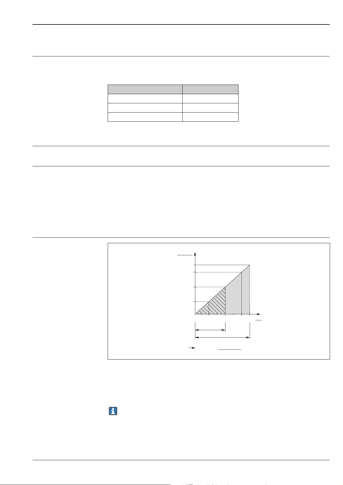
Load diagram
1 Power supply 11.5 to 30 V DC for intrinsically safe device versions
2 Power supply 11.5 to 45 V DC (versions with plug-in connector 35 V DC) for other types of protection and for uncertified device
versions
Maximum load resistance
R
Lmax
U Supply voltage
When operating via a handheld terminal or via a PC with an operating program, a minimum
communication resistance of 250 must be taken into account.
Endress+Hauser 15
A0023090
Page 16
Dead time, time constant
I
63 %
100 %
t
t1t
2
90 %
t
3
Deltapilot M FMB50/51/52/53
A0019786
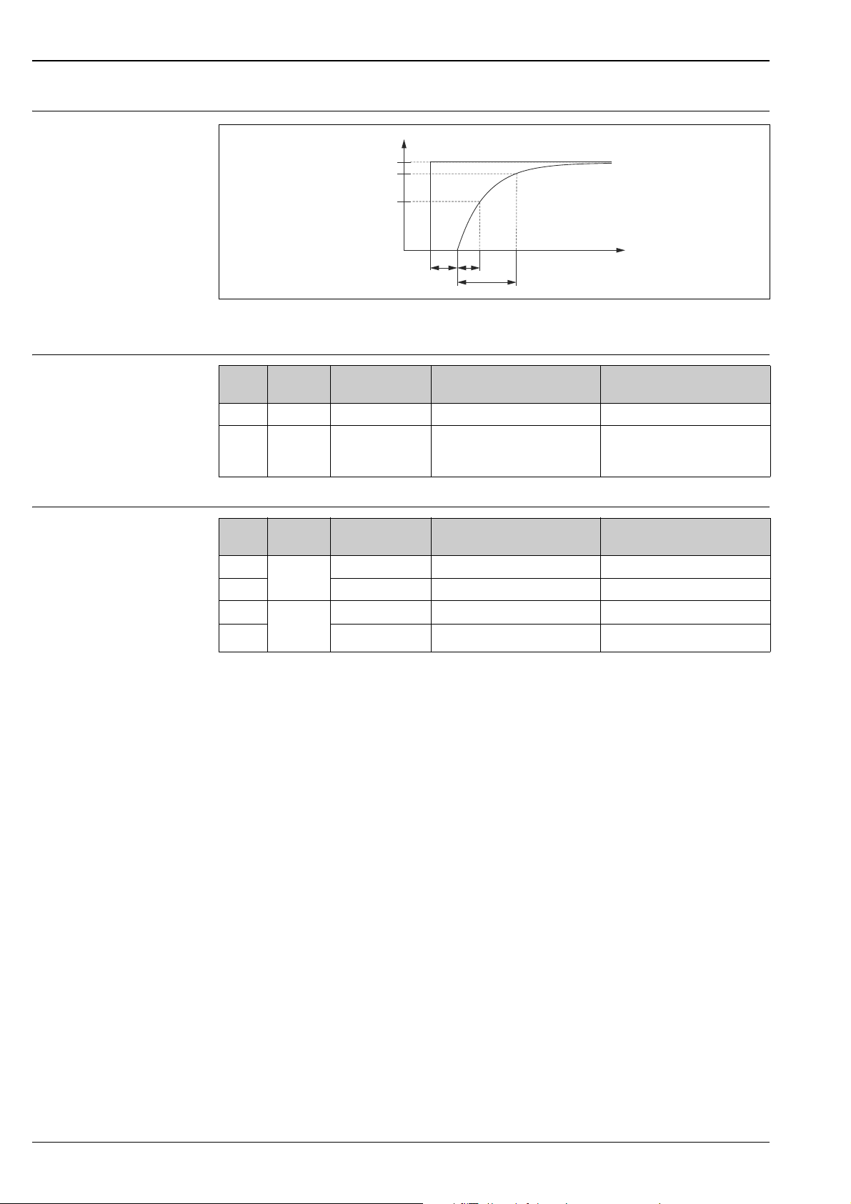
Presentation of the dead time and the time constant
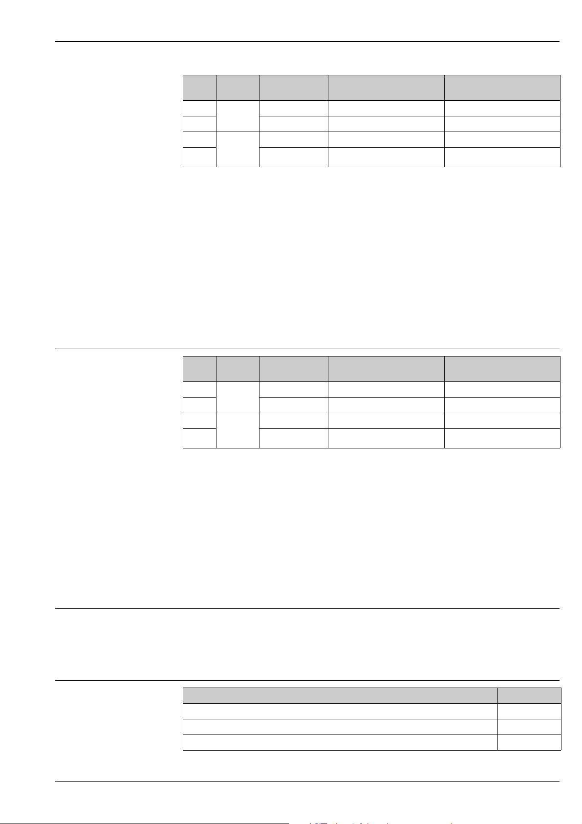
Dynamic behavior: current output
Dynamic behavior: HART
Type Dead time (t1)
max. FMB50 60 90 210
max. FMB51
min.
max. 1020 1110 1170
min. FMB51
max.
FMB52
FMB53
Type Dead time (t1)
FMB50
FMB52
FMB53
[ms]
500 250 -
[ms]
220 310 370
660 910 -
1460
Time constant T63 (= t2) [ms] Time constant T90 (= t3) [ms]
Dead time (t1) [ms] +
Time constant T63 (= t
1710
) [ms]
2
Dead time (t1) [ms] +
Time constant T90 (= t
-
) [ms]
3
Reading cycle
• Acyclic: max. 3/s, typical 1/s (depends on command # and number of preambles)
• Cyclic (Burst): max. 3/s, typical 2/s
The Deltapilot M commands the BURST MODE function for cyclic value transmission via the HART
communication protocol.
Cycle time (update time)
Cyclic (Burst): min. 300 ms
Response time
• Acyclic: min. 330 ms, typical 590 ms (depends on command # and number of preambles)
• Cyclic (Burst): min. 160 ms, typical 350 ms (depends on command # and number of preambles)
16 Endress+Hauser
Page 17
Deltapilot M FMB50/51/52/53
Dynamic behavior: PROFIBUS PA
Dynamic behavior: FOUNDATION Fieldbus
Type Dead time (t1)
[ms]
min.
max. 1195 1285 1345
min. FMB51
max.
FMB50
FMB52
FMB53
95 185 245
535 785 -
1635 1885 -
Dead time (t1) [ms] +
Time constant T63 (= t
) [ms]
2
Dead time (t1) [ms] +
Time constant T90 (= t
) [ms]
3
Reading cycle
• Cyclic: max. 30/s (dependent on the number and type of function blocks used in a closed-control
loop)
• Acyclic: typical 25/s
Cycle time (update time)
min. 100 ms
The cycle time in a bus segment in cyclic data communication depends on the number of devices, on
the segment coupler used and on the internal PLC cycle time.
Response time
• Cyclic: approx. 8 to 13 ms (depends on Min. Slave Interval)
• Acyclic: approx. 23 to 35 ms (depends on Min. Slave Interval)
Type Dead time (t1)
[ms]
min.
max. 1105 1195 1255
min. FMB51
max.
FMB50
FMB52
FMB53
105 195 255
545 795 -
1545
Dead time (t1) [ms] +
Time constant T63 (= t
1795
) [ms]
2
Dead time (t1) [ms] +
Time constant T90 (= t
-
) [ms]
3
Reading cycle
• Cyclic: max. 10/s (dependent on the number and type of function blocks used in a closed-control
loop)
• Acyclic: typical 5/s
Cycle time (update time)
Cyclic: min. 100 ms
Response time
• Cyclic: max. 20 ms (for standard bus parameter settings)
• Acyclic: typical 70 ms (for standard bus parameter settings)
Damping A damping affects all outputs (output signal, display).
• Via on-site display, handheld terminal or PC with operating program, continuous from 0...999 s
• Via DIP-switch on the electronic insert, switch position
"on" (= set value) and "off" (= damping switched off)
• Factory setting: 2 s
Firmware version
Designation Option
01.00.zz, FF, DevRev01 76
01.00.zz, PROFIBUS PA, DevRev01 77
01.00.zz, HART, DevRev01 78
1)
1) Product Configurator, "Firmware version" ordering feature
Endress+Hauser 17
Page 18

Deltapilot M FMB50/51/52/53
Galvanic isolation The following devices have a galvanic isolation between electronic and probe:
• FMB51, FMB52, FMB53
• FMB50 with separate housing
Protocol-specific data HART
Manufacturer ID 17 (11 hex)
Device Type Code 35 (23 hex)
Device Revision 01 (01 hex) - SW version 01.00.zz
HART specification 6
DD Revision • 01 (Dutch)
• 02 (Russian)
Device description files
(DTM, DD)
HART load Min. 250
HART device variables The measured values can be freely assigned to the device variables:
Supported functions • Burst mode
Information and files can be found:
• www.endress.com
• www.hartcomm.org
Measured values for PV (primary variable)
• Pressure
• Level
•Tank content
Measured values for SV, TV (second and third variable)
• Pressure
• Level
Measured values for QV (fourth variable)
•Temperature
• Additional Transmitter Status
• Device Locking
• Alternative operating modes
PROFIBUS PA
Manufacturer ID 17 (11 hex)
Ident number 1554 hex
Profile Version 3.02
• SW Version 01.00.zz
GSD Revision 5
DD Revision 1
GSD File Information and files can be found:
DD Files
Output values Measured values for PV (via Analog Input Function Block)
• www.endress.com
• www.profibus.org
• Pressure
•Flow
• Level
•Tank content
Measured values for SV
• Pressure
•Temperature
18 Endress+Hauser
Page 19

Deltapilot M FMB50/51/52/53
Input values Input value sent from PLC, can be shown on display
Supported functions • Identification & Maintenance
1) Only with Profile Version 3.02
Simple device identification via control system and nameplate
•Condensed status
• Automatic ident number adaptation and switchable to following ident
• Device locking: The device can be locked by hardware or software.
)
numbers
– 9700: Profile-specific transmitter identification number with the
"Classic" or "Condensed" status".
– 1503: Compatibility mode for the old Deltapilot M (DB50, DB50L,
DB51, DB52, DB53).
– 1555: Identification number for the new Deltapilot M (FMB50,
FMB51, FMB52, FMB53).
1)
:
Data of the FOUNDATION Fieldbus interface
Basic data
Device Type 0x1023
Device Revision 01 (hex)
DD Revision 0x01021
CFF Revision 0x000102
ITK Version 5.2.0
ITK Certification Driver No. IT067500
Link-Master (LAS) capable Yes
Link Master / Basic Device
selectable
Number of VCRs 44
Number of Link Objects in VFD 50
Number of FB-Schedule Objects 40
Yes; Factory setting: Basic Device
Virtual communication references (VCRs)
Permanent Entries 44
Client VCRs 0
Server VCRs 5
Source VCRs 8
Sink VCRs 0
Subscriber VCRs 12
Publisher VCRs 19
Link settings
Slot time 4
Min. inter PDU delay 12
Max. response delay 40
Endress+Hauser 19
Page 20

Deltapilot M FMB50/51/52/53
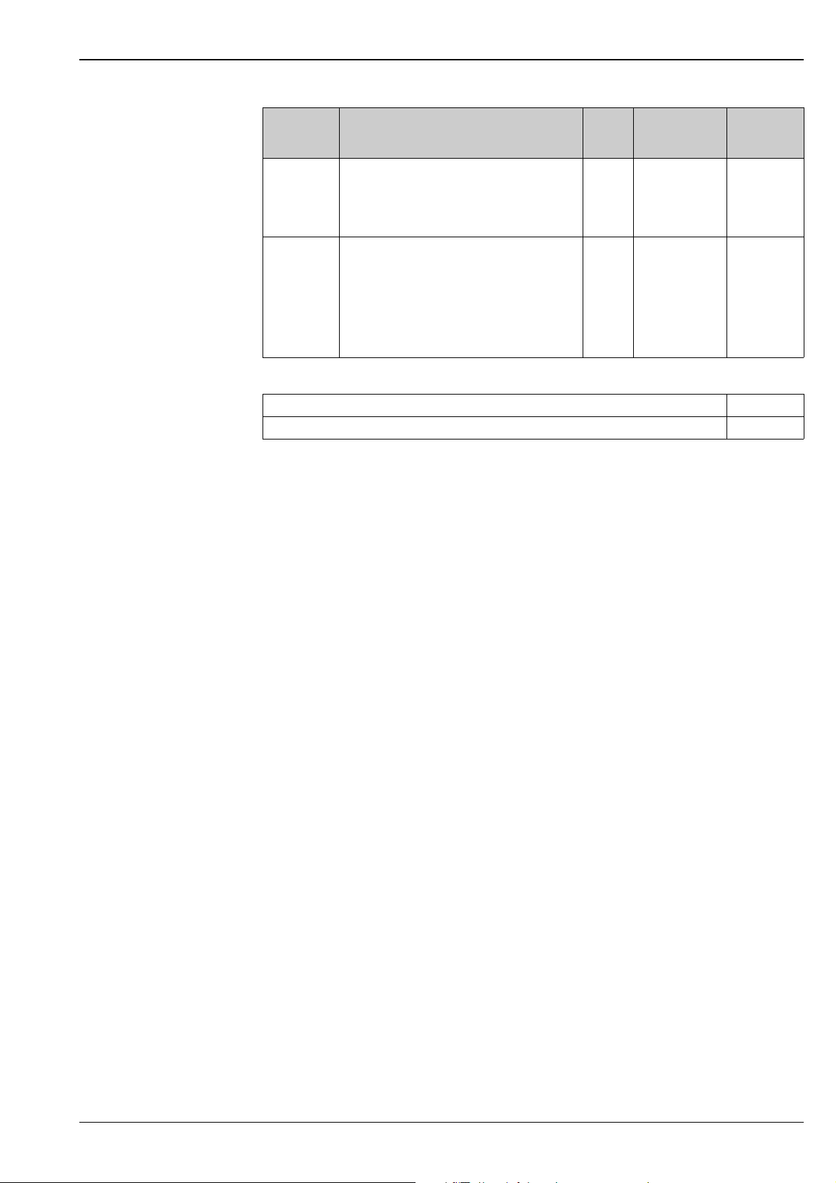
Transducer Blocks
Block Content Output values
TRD1 Block Contains all parameters related to the measurement • Pressure or level (channel 1)
• Process temperature (channel 2)
• Measured pressure value
(channel 3)
•Max. pressure (channel4)
• Level before linearization
(channel 5)
Diagnostic
Block
Display Block Contains parameters to configure the onsite display No output values
Contains diagnostic information • Error code via DI channels
(channel 10 to 15)
Function blocks
Block Content Number
of
blocks
Resource
Block
Analog Input
Block 1
Analog Input
Block 2
Digital Input
Block
Digital Output
Block
PID Block The PID Block serves as a proportional-integral-
Arithmetic
Block
Input Selector
Block
The Resource Block contains all the data that
uniquely identify the device. It is an electronic
version of a nameplate of the device.
The AI Block receives the measuring data from
the Sensor Block, (selectable via a channel
number) and makes the data available to other
function blocks at its output. Enhancement:
digital outputs for process alarms, fail safe mode.
This block contains the discrete data of the
Diagnose Block (selectable via a channel number
10 to 15) and provides them for other blocks at
the output.
This block converts the discrete input and thus
initiates an action (selectable via a channel
number) in the DP Flow Block or in the TRD1
Block. Channel 20 resets the counter for max.
pressure transgressions value and Channel 21
resets the Totalizer.
derivative controller and is used almost
universally for closed-loop-control in the field
including cascade and feedforward. Input IN can
be indicated on the display. The selection is
performed in the Display Block
(DISPLAY_MAIN_LINE_CONTENT).
This block is designed to permit simple use of
popular measurement math functions. The user
does not have to know how to write equations.
The math algorithm is selected by name, chosen
by the user for the function to be performed.
The Input Selector Block facilitates the selection
of up to four inputs and generates an output
based on the configured action. This block
normally receives its inputs from AI Blocks. The
block performs maximum, minimum, average
and ‘first good’ signal selection. Inputs IN1 to IN4
can be indicated on the display. The selection is
performed in the Display Block
(DISPLAY_MAIN_LINE_1_CONTENT).
1enhanced
2 25 ms enhanced
120 ms Standard
120 ms Standard
140 ms Standard
135 ms Standard
130 ms Standard
Execution time Functionality
20 Endress+Hauser
Page 21
Deltapilot M FMB50/51/52/53
Block Content Number
of
blocks
Signal
Characterizer
Block
Integrator
Block
Additional function block information:
Instantiate Function Block YES
Number of instantiate blocks 20
The Signal Characterizer Block has two sections,
each with an output that is a non-linear function
of the respective input. The non-linear function is
generated by a single look-up table with
21 arbitrary x-y pairs.
The Integrator Block integrates a variable as a
function of the time or accumulates the counts
from a Pulse Input Block. The block may be used
as a totalizer that counts up until reset or as a
batch totalizer that has a setpoint, where the
integrated or accumulated value is compared to
pre-trip and trip settings, generating a binary
signal when the setpoint is reached.
140 ms Standard
135 ms Standard
Execution time Functionality
Endress+Hauser 21
Page 22
WARNING
!
Terminal assignment
- +
1
2
3
4
5
6
7
Deltapilot M FMB50/51/52/53
Power supply
Incorrect connection can limit electrical safety!
‣ When using the measuring device in hazardous areas, installation must comply with the
corresponding national standards and regulations and the Safety Instructions or Installation or
Control Drawings ä 71 ff, "Safety instructions" and "Installation/Control Drawings" ordering
features.
‣ All explosion protection data are given in separate documentation which is available upon request.
The Ex documentation is provided with all Ex-systems as standard ä 71 ff, "Safety instructions"
and "Installation/Control Drawings" ordering features.
‣ According to IEC/EN61010 a suitable disconnector has to be installed for the device
‣ HART: Overvoltage protection HAW569-DA2B for the non-hazardous area, ATEX II 2 (1) Ex ia IIC
and IEC Ex ia can be ordered as an option (see "Ordering information" ordering feature).
‣ Protective circuits against reverse polarity, HF influences and overvoltage peaks are installed.
‣ The digital communication signal is transmitted to the bus via a 2-wire connection. The bus also
provides the power supply.
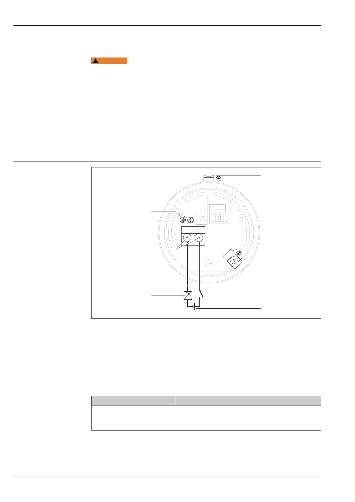
Electrical connection
1 External grounding terminal
2 Internal grounding terminal
3 Supply voltage
4 4...20 mA for HART devices
5 For HART and FOUNDATION Fieldbus devices: With a handheld terminal, all the parameters can be configured anywhere
along the bus line via menu operation.
6Terminals
7 For HART devices: test terminals, see section "Taking 4 to 20 mA test signal"
ä
22
Supply voltage 4 to 20 mA HART
Type of protection Supply voltage
• Intrinsically safe 11.5 ... 30 V DC
• Other types of protection
• Devices without certificate
11.5 to 45 V DC (versions with plug-in connection 35 V DC)
Taking 4 to 20 mA test signal
A 4 to 20 mA test signal may be measured via the test terminals without interrupting the
measurement.
22 Endress+Hauser
A0023505
Page 23
Deltapilot M FMB50/51/52/53
PROFIBUS PA
• Version for non-hazardous areas: 9 to 32 V DC
FOUNDATION Fieldbus
• Version for non-hazardous areas: 9 to 32 V DC
Current consumption • PROFIBUS PA: 11 mA ± 1 mA, switch-on current corresponds to IEC 61158-2, Clause 21
• FOUNDATION Fieldbus: 16 mA ± 1 mA, switch-on current corresponds to IEC 61158-2, Clause 21
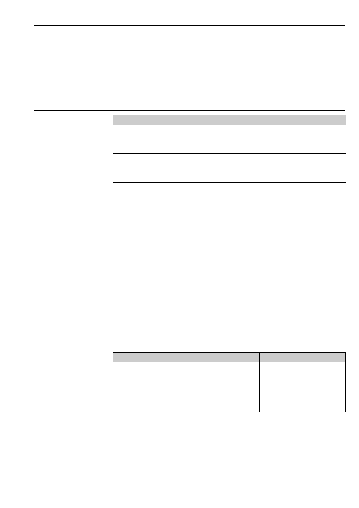
Electrical connection
Cable entry Degree of protection Option
M20 gland IP66/68 NEMA 4X/6P A
G ½" thread IP66/68 NEMA 4X/6P C
NPT ½" thread IP66/68 NEMA 4X/6P D
M12 plug IP66/67 NEMA 4X/6P I
7/8" plug IP66/68 NEMA 4X/6P M
HAN7D connector, 90 deg IP65 P
PE cable 5m
M16 valve connector IP64 V
1) Product Configurator, "Electrical connection" ordering feature
2) Only for FMB50
2)
IP66/68 NEMA4X/6P + pressure compensation via cable S
1)
PROFIBUS PA
The digital communication signal is transmitted to the bus via a 2-wire connection. The bus also
provides the power supply. For further information on the network structure and grounding, and for
further bus system components such as bus cables, see the relevant documentation, e.g. Operating
Instructions BA00034S "PROFIBUS DP/PA: Guidelines for planning and commissioning" and the
PNO Guideline.
FOUNDATION Fieldbus
The digital communication signal is transmitted to the bus via a 2-wire connection. The bus also
provides the power supply. For further information on the network structure and grounding and for
further bus system components such as bus cables, see the relevant documentation, e.g. Operating
Instructions BA00013S "FOUNDATION Fieldbus Overview" and the FOUNDATION Fieldbus Guideline.
Terminals • Supply voltage and internal ground terminal: 0.5 ... 2.5 mm² (20...14 AWG)
• External ground terminal: 0.5 ... 4 mm² (20...14 AWG)
Cable entry
Approval Type Clamping area
Standard, CSA GP
ATEX II1/2G or II2G Ex ia,
IEC Ex ia Ga/Gb or Ex ia Gb,
FM/ CSA IS
ATEX II1/2D Ex t, II1/2GD Ex ia,
II3G Ex nA,
IEC Ex t Da/Db
Plastic M20x1.5 5 to 10 mm (0.2 to 0.39 in)
Metal M20x1.5 (Ex e) 7 to 10.5 mm (0.28 to 0.41 in)
For other technical data, see the housing section ä 36 ff".
Endress+Hauser 23
Page 24
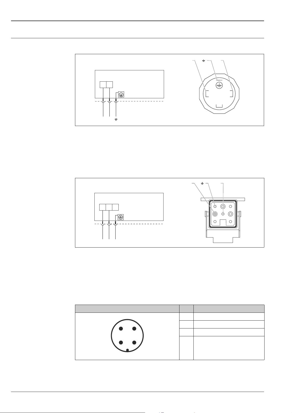
Connector Devices with valve connector
+
21
–
+
AB
BU BN GNYE
2
1
3
+
–
–
Han7D
–
+
+–
–
+
1
5
4
6
7
8
2
3
AB
21
3
4
BN = brown, BU = blue, GNYE = green/yellow
A Electrical connection for devices with valve connector
B View of the connection on the device
Material: PA 6.6
Deltapilot M FMB50/51/52/53
A0023097
Devices with Harting plug Han7D
A Electrical connection for devices with Harting plug Han7D
B View of the connection on the device
Material: CuZn, gold-plated contacts of plug-in jack and connector
Devices with M12 plug
PIN assignment for M12 connector
PIN assignment for M12 connector PIN Meaning
1Signal +
2Not assigned
3Signal –
4Earth
A0019990
Endress+Hauser offers the following accessories for devices with an M12 plug:
Plug-in jack M 12x1, straight
• Material: body PA; coupling nut CuZn, nickel-plated
24 Endress+Hauser
A0011175
Page 25

Deltapilot M FMB50/51/52/53
2
1
4
3
• Degree of protection (fully locked): IP66/67
• Order number: 52006263
Plug-in jack M 12x1, elbowed
• Material: body PBT/PA; coupling nut GD-Zn, nickel-plated
• Degree of protection (fully locked): IP66/67
• Order number: 71114212
Cable 4x0.34 mm² (20 AWG) with M12 socket, elbowed, screw plug, length 5 m (16 ft)
• Material: body PUR; coupling nut CuSn/Ni; cable PVC
• Degree of protection (fully locked): IP66/67
• Order number: 52010285
Devices with 7/8" plug
PIN assignment for 7/8" connector
PIN assignment for 7/8" connector PIN Meaning
1Signal –
2Signal +
3 Not assigned
4Shield
External thread: 7/8 - 16 UNC
• Material: 316L (1.4401)
• Protection: IP66/68
Cable specification HART
• Endress+Hauser recommends using twisted, shielded two-wire cables.
• The cable outer diameter depends on the cable entry used.
PROFIBUS PA
Use a twisted, shielded two-wire cable, preferably cable type A
For further information on the cable specifications, see Operating Instructions BA00034S
"PROFIBUS DP/PA: Guidelines for planning and commissioning", the PNO Guideline 2.092
"PROFIBUS PA User and Installation Guideline" and IEC 61158-2 (MBP).
FOUNDATION Fieldbus
Use a twisted, shielded two-wire cable, preferably cable type A
A0011176
For further information on the cable specifications, see Operating Instructions BA00013S
"FOUNDATION Fieldbus Overview", FOUNDATION Fieldbus Guideline and IEC 61158-2 (MBP).
Start-up current HART 12 mA or 22 mA (selectable)
Residual ripple No influence on 4 to 20 mA signal up to 5 % residual ripple within the permitted voltage range
[according to HART hardware specification HCF_SPEC-54 (DIN IEC 60381-1)]
Influence of power supply 0.001 % of URL/V
Endress+Hauser 25
Page 26
Deltapilot M FMB50/51/52/53
1
2
3
4
+
-
+
-
rt
sw
+
-
A
B
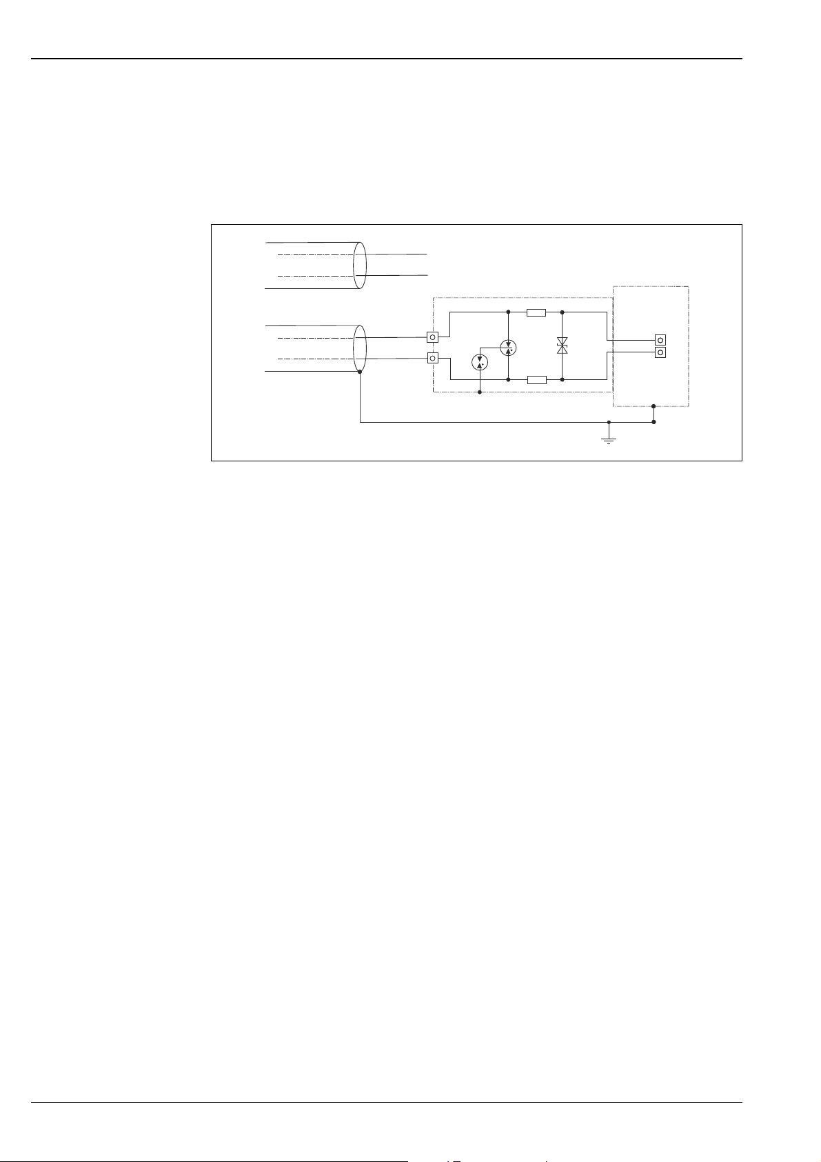
Overvoltage protection (optional)
The device can be fitted with overvoltage protection. The overvoltage protection is mounted at the
factory on the housing thread (M20x1.5) for the cable gland and is approx. 70 mm (2.76 in) in length
(take additional length into account when installing). The device is connected as illustrated in the
following graphic.
For details refer to TI001013KEN, XA01003KA3 and BA00304KA2.
Ordering information:
Product Configurator, "Mounted accessories" ordering feature, option NA
A0023111
A Without direct shield grounding
B With direct shield grounding
1 Incoming connection cable
2 HAW569-DA2B
3 Unit to be protected
4 Connection cable
26 Endress+Hauser
Page 27

Deltapilot M FMB50/51/52/53
12
Performance characteristics
Reference operating conditions
• As per IEC 60770
• Ambient temperature T
= constant, in the range of: +21 to +33 °C (+70 to 91°F)
A
• Humidity = constant, in the range of: 5 to 80 % RH
• Ambient pressure pA = constant, in the range of: 860 to 1060 mbar (12.47 to 15.37 psi)
• Position of the measuring cell: constant, in range: FMB50: horizontally 1°
FMB51/FMB52/FMB53: vertically 1°
• Input of LOW SENSOR TRIM and HIGH SENSOR TRIM for lower range value and upper range value
• Span based on zero point
• Material of the process isolating diaphragm: Alloy C276 (2.4819) and Alloy C276 (2.4819) with
coating (AuRh or AuPt)
• Measuring cell material (meter body): Alloy C276 (2.4819), 316L (1.4435)
• Filling oil: synthetic oil (FDA)/inert oil
• Supply voltage: 24 V DC ± 3 V DC
• Load with HART: 250
Influence of orientation • < 2.3 mbar (0.0345 psi) when using synthetic oil (FDA)
• < 5 mbar (0.075 psi) when using inert oil
Position-dependent zero point shift can be corrected ä 29, "General installation instructions"
ordering feature.
Calibration position
A0023545
1FMB50
2 FMB51, FMB52, FMB53
To minimize the effect of the orientation (e.g. in the case of vertical device installation), position offset
is preset at the factory.
Resolution • Current output: 1 A
• Display: can be set (factory setting: presentation of the maximum accuracy of the transmitter)
Reference accuracy The reference accuracy comprises the non-linearity according to limit point setting, hysteresis and
non-reproducibility as per IEC 60770. The data refer to the calibrated span.
Reference accuracy in % of the calibrated span
Measuring cell TD "Standard" option
0.1 bar (1.5 psi)
0.4 bar (6 psi)
1.2 bar (18 psi)
4 bar (60 psi)
10 bar (150 psi)
• TD 1:1 to TD 2:1
• TD > 2:1 to TD 4:1
• TD 1:1 to TD 4:1
• TD > 4:1 to TD 10:1
• TD 1:1 to TD 2:1
• TD > 2:1 to TD 12:1
• TD 1:1 to TD 4:1
• TD > 4:1 to TD 20:1
• TD 1:1 to TD 2.5:1
• TD > 2.5:1 to TD 20:1
•< 0.2
• < 0.1 x TD
•< 0.2
• < 0.05 x TD
•< 0.2
• < 0.1 x TD
•< 0.2
• < 0.05 x TD
•< 0.2
• < 0.08 x TD
1)
"Platinum" option
• < 0.15
• < 0.075 x TD
• < 0.15
• < 0.0375 x TD
•< 0.1
• < 0.05 x TD
•< 0.1
• < 0.025 x TD
•< 0.1
• < 0.04 x TD
1)
1) Product Configurator, "Reference accuracy" ordering feature
Endress+Hauser 27
Page 28
Deltapilot M FMB50/51/52/53
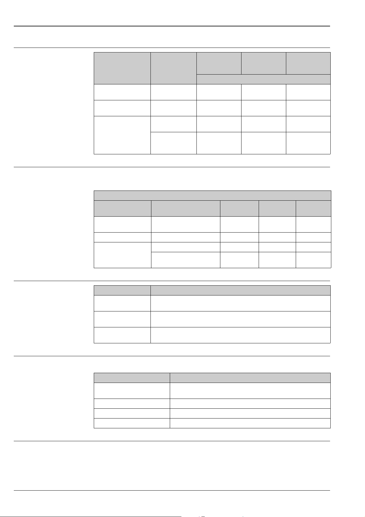
Thermal change in the zero output and the output span
Version Measuring cell -10 to +60 °C
(+14 to +140°F)
FMB50
FMB51/52/53 snap-on
FMB51/52/53 welded
FMB50/51/52/53
0.1 bar (1.5 psi)
0.1 bar (1.5 psi)
0.4 bar (6 psi)
1.2 bar (18 psi),
4 bar (60 psi),
10 bar (150 psi)
< (0.32 + 0.30 x
TD)
< (0.32 + 0.50 x
TD)
< (0.31 + 0.25 x
TD)
< (0.31 + 0.10 x
TD)
60 to 85 °C
(140 to 185°F)
% of the calibrated span
< (0.34 + 0.40 x
TD)
< (0.34 + 0.60 x
TD)
< (0.32 + 0.30 x
TD)
< (0.32 + 0.15 x
TD)
Only FMB50:
85 to 100 °C
(185 to 212°F)
< (0.34 + 0.55 x
TD)
-
-
< (0.33 + 0.20 x
TD)
Total performance The "Total performance" specification comprises the non-linearity including hysteresis, non-
reproducibility as well as the thermal change in the zero point.
Total performance in % of the URL
Version Measuring cell -10 to +60 °C
(+14 to +140°F)
FMB50
FMB51/52/53 snap-on
FMB51/52/53 welded 0.1 bar (1.5 psi) < 0.8 < 1 < 1.4
FMB50/51/52/53
0.1 bar (1.5 psi) < 0.35 < 0.45 < 0.6
0.4 bar (6 psi) < 0.35 < 0.45 < 0.6
1.2 bar (18 psi), 4 bar (60 psi),
10 bar (150 psi)
< 0.15 < 0.2 < 0.25
60 to 85 °C
(140 to 185°F)
85 to 100 °C
(185 to 212°F)
Long-term stability
Measuring cell Long-term stability [%]
0.1 bar (1.4 psi)
0.4 bar (6 psi)
1.2 bar (18 psi)
4 bar (60 psi)
10 bar (150 psi)
• < 0.18 of the upper range limit (URL) / year
• < 0.45 of the upper range limit (URL) / 5 years
• < 0.1 of the upper range limit (URL) / year
• < 0.25 of the upper range limit (URL) / 5 years
• < 0.05 of the upper range limit (URL) / year
• < 0.125 of the upper range limit (URL) / 5 years
Total error The total error comprises the long-term stability and the total performance:
Measuring cell % of the URL/year (in the permitted temperature range)
0.1 bar (1.5 psi)
0.4 bar (6 psi) 0.61
1.2 bar (18 psi) 0.27
4 bar (60 psi), 10 bar (150 psi) 0.25
•Snap-on: 0.63
• Welded: 1.0
Warm-up period • 4 to 20 mA HART:
– FMB50 = 5 s
– FMB51/FMB52/FMB53 = 8 s
•PROFIBUS PA: 8 s
• FOUNDATION Fieldbus: 20 s (after a TOTAL-reset 45 s)
28 Endress+Hauser
Page 29
Deltapilot M FMB50/51/52/53
WARNING
!
L
E
17 (0.67)
Installation
General installation instructions
FMB50 Level measurement
• The position-dependent zero point shift can be corrected:
– directly at the device via an operating key
– directly at the device via operating keys on the display
– via digital communication if the cover is not open
Risk of explosion!
In hazardous areas, comply strictly with the safety instructions when the housing cover is closed and
open.
• The local display can be rotated in 90° stages.
• Always install the device below the lowest measuring point.
• Do not install the device at the following positions:
– in the filling curtain
– in the tank outflow
– or at a point in the tank that can be affected by pressure pulses from the agitator
• The calibration and functional test can be carried out more easily if you mount the device
downstream of a shutoff device.
• Deltapilot M must be included in the insulation for media that can harden when cold.
Pressure measurement in gases
Mount Deltapilot M with shutoff device above the tapping point so that any condensate can flow into
the process.
Pressure measurement in steams
• Mount Deltapilot M with siphon above the tapping point.
• Fill the siphon with liquid before commissioning.
The siphon reduces the temperature to almost the ambient temperature.
Pressure measurement in liquids
Mount Deltapilot M with the shutoff device below or at the same level as the tapping point.
FMB51/FMB52/FMB53 • When mounting rod and cable versions, make sure that the probe head is located at a point as free
as possible from flow. To protect the probe from impact resulting from lateral movement, mount the
probe in a guide tube (preferably made of plastic) or secure it with a clamping fixture.
• In the case of devices for hazardous areas, comply strictly with the safety instructions when the
housing cover is open.
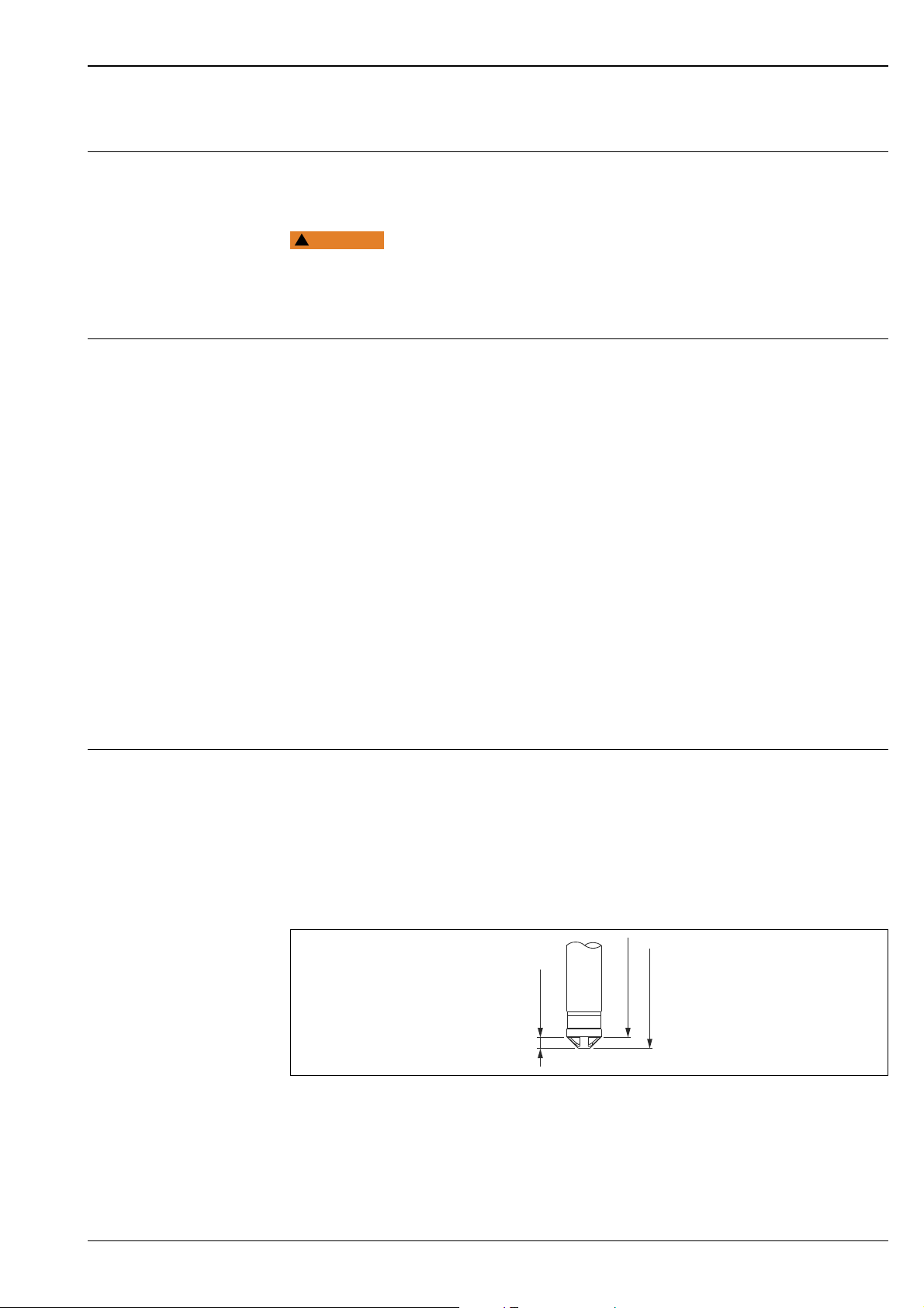
• The length of the extension cable or the probe rod is based on the planned level zero point.
The height of the protective cap must be taken into consideration when designing the layout of the
measuring point. The level zero point (E) corresponds to the position of the process isolating
diaphragm.
Level zero point = E; top of the probe = L.
Endress+Hauser 29
Page 30

• Suspension clamp (required for FMB53)
61 (2.4)
238 (9.37)
Material: ä 56 ff
Ordering information:
Order number: 52010869 ä 67 ff
Product Configurator, "Accessory enclosed" ordering feature, option "PO".
Engineering unit mm (in)
Deltapilot M FMB50/51/52/53
A0023566
Supplementary installation instructions
Process isolating diaphragm
• Do not clean or touch process isolating diaphragms with hard or pointed objects.
• The process isolating diaphragm in the rod and cable version is protected against mechanical
damage by a plastic cap.
Seal
• Deltapilot M devices with a G 1 ½ thread:
When screwing the device into the tank, the flat seal has to be positioned on the sealing surface of
the process connection. To avoid additional strain on the process isolating diaphragm, the thread
should never be sealed with hemp or similar materials.
• Deltapilot M devices with NPT threads:
– Wrap Teflon tape around the thread to seal it.
– Tighten the device at the hexagonal bolt only. Do not turn the device at the housing.
– Do not overtighten the thread when screwing in the screw. Max. torque: 20 to 30 Nm
(14.75 to 22.13 lbf ft)
Sealing the probe housing
Moisture must not penetrate the housing when mounting the device, establishing the electrical
connection and during operation.
• Always firmly tighten the housing cover and the cable entries.
• Lubricant is provided on the O-ring seal in the housing cover and on the thread of the aluminum
cover. To ensure that the cover seals tight, any lubricant which has been removed must be replaced.
Use silicone grease or graphite paste as the lubricant. Mineral oil-based grease can destroy the
O-ring.
PE cable length > 300 m (984 ft)
• Two suspension clamps must be used for PE cables longer than 300 meters (984 ft).
Cable length tolerances
•FMB52
– Cable length < 5 m (16 ft): up to -35 mm (-1.38 in)
– Cable length 5...10 m (16...33 ft): up to -75 mm (-2.95 in)
– Cable length 10...100 m (33...328 ft): up to -100 mm (-3.94 in)
•FMB53
– Cable length < 5 m (16 ft): up to ±17.5 mm (±0.69 in)
– Cable length 5...10 m (16...33 ft): up to ±37.5 mm (±1.48 in)
– Cable length 10...100 m (33...328 ft): up to ±50 mm (±1.97 in)
Rod length tolerances
•FMB51
– Rod length < 4000 mm (157 in): up to -4 mm (-0.16 in)
Wall and pipe mounting Endress+Hauser offers a mounting bracket for installing the device on pipes or walls. The mounting
bracket is
• included in the delivery for the FMB50/51/52 with a separate housing (available for order via
feature 600) and for the FMB53
• available for order as a separate accessory (Part No.: 71102216).
For the dimensions, see ä 50.
30 Endress+Hauser
Page 31

Deltapilot M FMB50/51/52/53
r ³120 (4.72)
4
5
231
"Separate housing" version With the "separate housing" version, you are able to mount the housing with the electronics insert at a
distance from the measuring point. This allows for trouble-free measurement:
• Under particularly difficult measuring conditions (at installation locations that are cramped or
difficult to access)
• If rapid cleaning of the measuring point is required
• If the measuring point is exposed to vibrations
You can choose between different cable versions:
• PE (2 m (6.6 ft), 5 m (16 ft) and 10 m (33 ft))
• FEP (5 m (16 ft)).
Ordering information:
Product Configurator, "Separate housing" ordering feature
Product Configurator, "Enclosed accessories" ordering feature, option PA
For the dimensions, see ä 50.
Engineering unit mm (in)
In the case of the "separate housing" version, the sensor is delivered with th e process connection and cable ready mounted. The housing
and a mounting bracket are enclosed as separate units. The cable is provided with a socket at both ends. These sockets are simply
connected to the housing and the sensor.
1 Process connection with sensor - see the following section for the degrees of protection
2 Process connection adapter (weight 0.93 kg (2.05 lbs))
3 Cable (weight 0.05 kg/Meter (0.11 lbs/meter)), both ends are fitted with a socket
4 Mounting bracket provided, suitable for pipe and wall mounting (for pipes from 1 1/4" up to 2" diameter)
5 Housing with electronic insert - degrees of protection
ä
33 ff
Degree of protection for the process connection and sensor with the use of
•FEP cable:
–IP69
1)
– IP66 NEMA 4/6P
– IP68 (1.83 mH
O for 24 h) NEMA 4/6P
2
•PE cable:
– IP66 NEMA 4/6P
– IP68 (1.83 mH
Technical data of the PE and FEP cable:
• Minimum bending radius: 120 mm (4.72 in)
O for 24 h) NEMA 4/6P
2
• Cable extraction force: max. 450 N (101 lbf)
• Resistance to UV light
Use in hazardous area:
• Intrinsically safe installations (Ex ia/IS)
• FM/CSA IS: for Div.1 installation only
A0023567
1) Identification of IP protection category according to DIN EN 60529. The earlier designation “IP69K” according to DIN 40050 Part 9 is no longer
valid (the standard was withdrawn on November 1, 2012). The tests required for both standards are identical.
Endress+Hauser 31
Page 32

Deltapilot M FMB50/51/52/53
NOTICE
Oxygen applications Oxygen and other gases can react explosively to oils, grease and plastics. As a result, the following are
some of the precautions that must be taken:
– All components of the system, such as measuring devices, must be cleaned in accordance with the
BAM (DIN 19247) requirements.
– Depending on the materials used, a certain maximum temperature and maximum pressure must not
be exceeded for oxygen applications. The maximum temperature T
for oxygen applications is
max
60 °C (140°F).
The devices suitable for gaseous oxygen applications are listed in the following table with the
specification p
max
.
Order code for devices1) cleaned for
oxygen applications
2)
FMB50
FMB51
1) Only device, not accessory or enclosed accessory
2) Product Configurator, "Service" ordering feature, option "HB"
3) ä 14, "Measuring range" ordering feature and ä 36 ff, "Mechanical construction" ordering feature
4) Oxygen applications possible with FKM seal and inert oil.
)
p
for oxygen applications
max
• Depends on the lowest-rated element, with regard to pressure, of
the selected components: over pressure limit (OPL) of the sensor or
process connection (1.5 x PN)
• Depends on filling oil
• Depends on the lowest-rated element, with regard to pressure, of
the selected components: over pressure limit (OPL) of the sensor or
process connection (1.5 x PN)
• Depends on filling oil
• Depends on seal material
3)
4)
)
)
PWIS cleaning Special cleaning of the transmitter to remove paint-wetting substances, for use in paint shops, for
instance.
Ordering information: Product Configurator, "Service" ordering feature, option HC
The stability of the materials used must be checked before using them in the medium.
The protective cap of the process isolating diaphragm must be removed if necessary (FMB51/FMB52/
FMB53).
Applications with hydrogen A gold-plated metal process isolating diaphragm offers universal protection against hydrogen
diffusion, both in gas applications and in applications with aqueous solutions.
Applications with hydrogen in aqueous solutions
A gold/rhodium-plated metal process isolating diaphragm (AU/Rh) offers effective protection
against hydrogen diffusion.
Special measuring cells for
acids, alkalis or sea water
For acids, alkalis or sea water, Endress+Hauser offers process isolating diaphragms with a gold/
platinum coating.
(not FMB50)
With temperature exposure (up to 85°C(185°F)) there is an additional zero point deviation of 1.1
mbar (0.0165 psi).
Ordering information:
Product Configurator, "Process isolating diaphragm material" ordering feature, option N
32 Endress+Hauser
Page 33
Deltapilot M FMB50/51/52/53
Environment
Ambient temperature limits
Storage temperature range
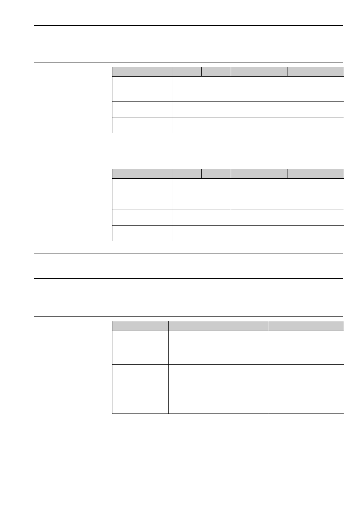
Version FMB50 FMB51 FMB52 FMB53
Without LCD display –40 °C to +85 °C
(-40°F to +185°F)
With LCD display
With M12 plug , elbowed -25 °C to +85 °C
With separate housing
(PE and FEP cable)
1) Extended temperature application range (-40 °C to +85 °C (–40°F to +185°F)) with restrictions in optical
properties such as display speed and contrast
Version FMB50 FMB51 FMB52 FMB53
Without LCD display –40 °C to +90 °C
With LCD display –40 °C to +85 °C
With M12 plug , elbowed -25 °C to +90 °C
With separate housing and
FEP cable
1)
(-13°F to +185°F)
(-40°F to +194°F)
(-40°F to +185°F)
(-13°F to +194°F)
With PE cable: -40 °C to +70 °C (-40°F to +158°F)
With FEP cable: –40 °C to +80 °C (-40°F to +176°F)
–20 °C to +70 °C (-4°F to +158°F)
With PE cable: -25 °C to +70 °C (-13°F to +158°F)
With FEP cable: -25 °C to +80 °C (-13°F to +176°F)
-20 °C to +60 °C (-4°F to +140°F)
With PE cable: -40 °C to +70 °C (-40°F to +158°F)
With FEP cable: –40 °C to +80 °C (-40°F to +176°F)
With PE cable: -25 °C to +70 °C (-13°F to +158°F)
With FEP cable: -25 °C to +80 °C (-13°F to +176°F)
-20 °C to +60 °C (-4°F to +140°F)
Climate class Class 4K4H (air temperature: –20 to 55 °C (–4 to +131°F), relative humidity: 4 to 100%) satisfied as per
DIN EN 60721-3-4 (condensation possible)
Degree of protection • F31 housing: IP 68 (1.83 mH
O for 24 h)
2
• Ordering information:
Product Configurator, "Electrical connection" ordering feature
• Separate housing ä 31
Vibration resistance
Device/accessory Test standard Vibration resistance
FMB50, FMB52, FMB53 GL VI-7-2
• Part 7: Guidelines for the Performance of
Type Approvals
• Chapter 2: Test Requirements for Electrical /
Electronic Equipment and Systems
FMB50, FMB52, FMB53
with mounting bracket
FMB51 IEC 60068-2-6 Guaranteed for:
IEC 61298-3
Guaranteed for:
5 to 25 Hz: ±1.6 mm (0.06 in);
25 to 100 Hz: 4 g
in all 3 planes
Guaranteed for:
10 to 60 Hz: ±0.15 mm (0.01 in);
60 to 500 Hz: 2 g
in all 3 planes
10 to 60 Hz: ±0.075 mm (0.003 in)
60 to 150 Hz 1g in all 3 planes
Endress+Hauser 33
Page 34

Deltapilot M FMB50/51/52/53
Electromagnetic compatibility
• Electromagnetic compatibility as per all the relevant requirements of the EN 61326 series and
NAMUR Recommendation EMC (NE21).
• Max. deviation during EMC-tests < 0.5% of the span
• All tests were performed with full measurement range (TD 1:1).
Further details can be found in the manufacturer declaration.
34 Endress+Hauser
Page 35

Deltapilot M FMB50/51/52/53
WARNING
!
Process
Process temperature range
–10 °C to +100 °C (+14°F to 212°F)
135 °C (275°F) for 30 min. maximum
Lateral load FMB51 (static) 30 Nm
Pressure specifications
The maximum pressure for the measuring device depends on the lowest-rated element with
regard to pressure ä 14 ff, "Measuring range" ordering feature and ä 36 ff "Mechanical
construction" ordering feature
‣ Only operate the measuring device within the prescribed limits!
‣ The Pressure Equipment Directive (EC Directive 97/23/EC) uses the abbreviation "PS". The
abbreviation "PS" corresponds to the MWP (maximum working pressure) of the measuring device.
‣ The MWP (maximum working pressure) is specified on the nameplate. This value refers to a
reference temperature of +20 °C (68°F), (100°F (38 °C) for ANSI flanges), and may be applied to the
device for an unlimited time. Pay attention to pressure-temperature dependencies. Please refer to
the following standards for pressure values permitted at higher temperatures
EN 1092-1: 2001 Tab. 18
ASME B 16.5a – 1998 Tab. 2-2.2 F316
ASME B 16.5a – 1998 Tab. 2.3.8 N10276
JIS B 2220.
‣ OPL (Over Pressure Limit = sensor overload limit):
The test pressure corresponds to the over pressure limit of the sensor and may only be applied for
a limited time period to ensure measurement within specification and in order to avoid permanent
damage. In the case of sensor range and process connections where the over pressure limit (OPL)
of the process connection is smaller than the nominal value of the sensor, the device is set at the
factory, at the very maximum, to the OPL value of the process connection. If you want to use the
entire sensor range, select a process connection with a higher OPL value.
‣ Oxygen applications:
The values for "p
be exceeded.
‣ Avoid steam hammering!
Steam hammering can cause zero point drift.
Recommendation: Residue (such as condensation or drops of water) can remain at the process
isolating diaphragm after CIP cleaning and lead to local steam hammering if immediately steam is
introduced. In practice, drying the process isolating diaphragm (e.g. by blowing off excess
moisture) has proven to be a successful way of avoiding steam hammering.
FMB50 FMB51 FMB52 FMB53
max
and T
–10 °C to +85 °C
(+14°F to +185°F)
Min. process temperature when using the KALREZ seal:
-3 °C (27°F)
2)
for oxygen applications" as per ä 32, "Oxygen applications" may not
max
With PE cable: -10 °C to +70 °C (-14°F to 158°F)
With FEP cable: –10 °C to +80 °C (-14°F to 176°F)
2) With regard to their stability-temperature property, the materials 1.4435 and 1.4404 are grouped together under 13EO in EN 1092-1 Tab. 18. The
chemical composition of the two materials can be identical.
Endress+Hauser 35
Page 36
Mechanical construction
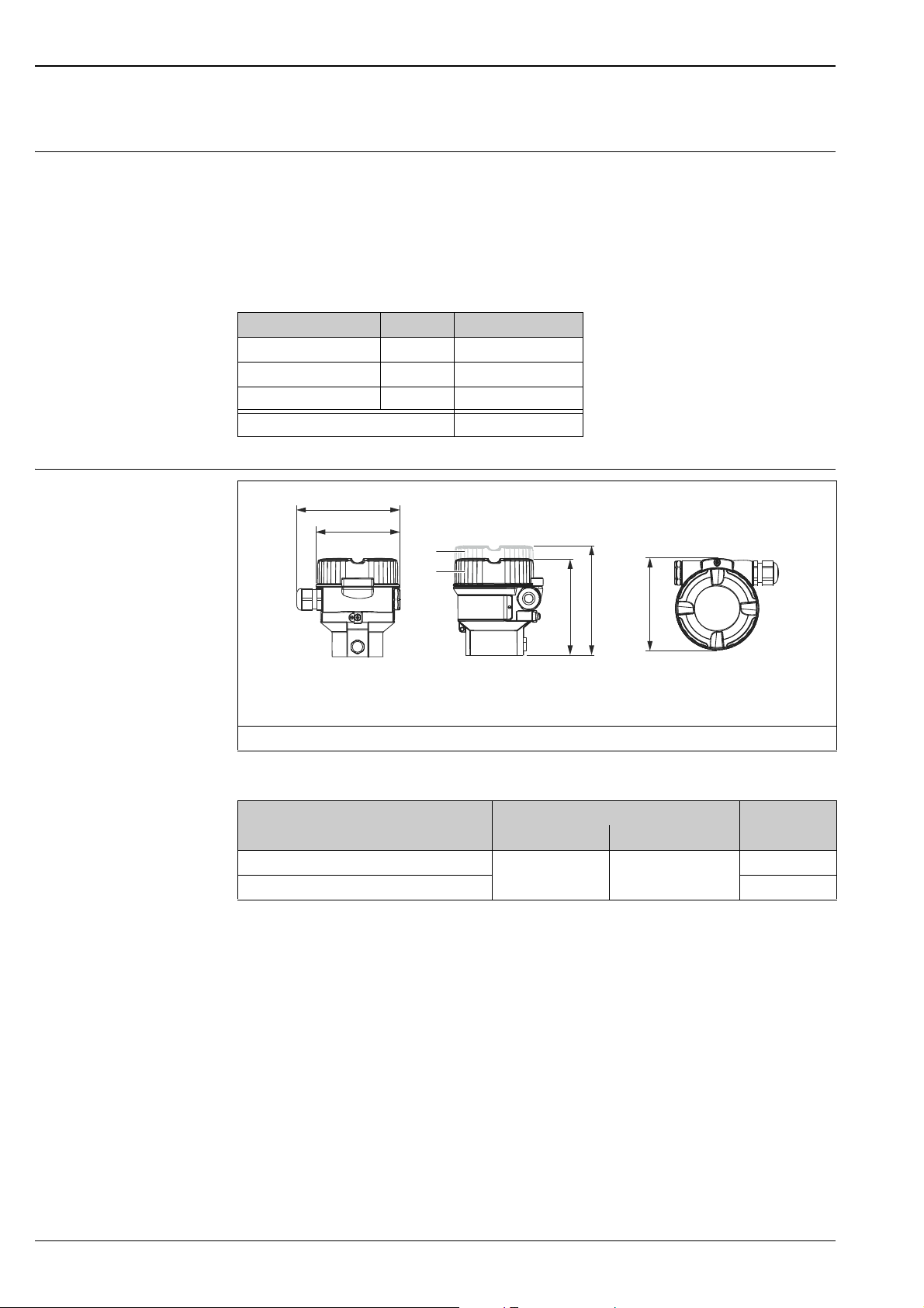
115 (4.53)
103 (4.06)
112 (4.41)
127 (5)
94 (3.7)
1
2
Device height The device height is calculated from
• the height of the housing and
• the height of the individual process connection.
The individual heights of the components are listed in the following sections. To calculate the device
height simply add up the individual heights of the components. Where applicable also take into
consideration the installation distance (space that is used to install the device).
You can use the following table for this purpose:
Section Page Height
Housing height ä 36 ff
Process connections ä 37 ff
Installation distance
Device height
F31 housing, aluminum
Deltapilot M FMB50/51/52/53
Engineering unit mm (in)
1Cover with viewing window
2 Cover without viewing window
Front view, left-hand side view, top view
Material Weight kg (lbs) Option
With display Without display
Aluminum
Aluminum with glass viewing window
1) Product Configurator, "Housing" ordering feature
2) Degree of protection dependent on cable entry used ä 23
2)
)
1.1 (2.43) 1.0 (2.21)
I
J
A0023569
1)
36 Endress+Hauser
Page 37
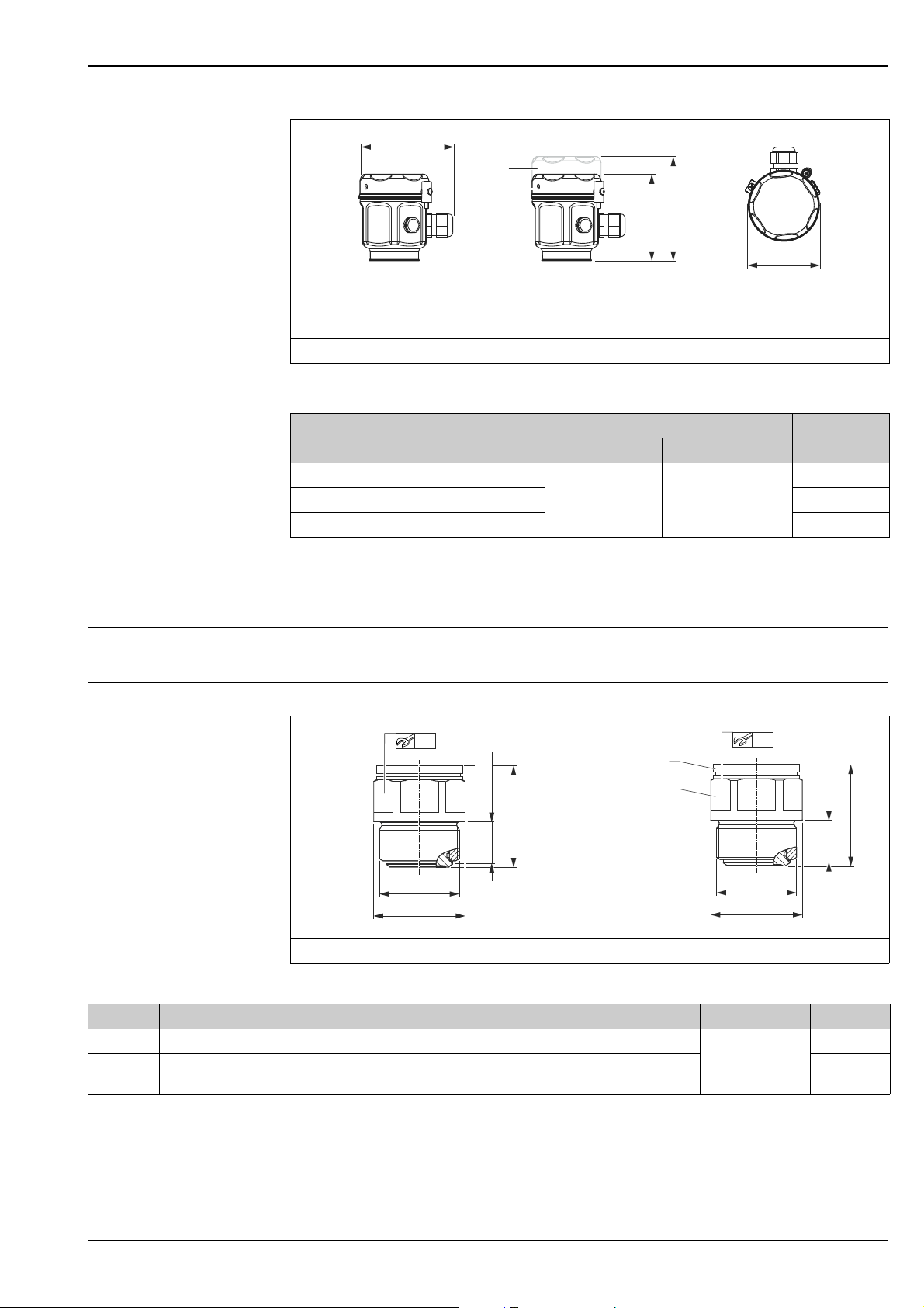
Deltapilot M FMB50/51/52/53
76 (3)
100 (3.94)
1
2
93 (3.66)
112 (4.41)
59 (2.32)
25 (0.98)
50
G 1½" A
ø55 (2.17)
59 (2.32)
25 (0.98)
50
G 1½" A
ø55 (2.17)
1
2
F15 housing, stainless steel (hygienic)
Engineering unit mm (in)
1Cover with viewing window
2 Cover without viewing window
Front view, left-hand side view, top view
A0023570
Diameter of the process isolating diaphragm
Process connections FMB50, FMB51, FMB52
Material Weight kg (lbs) Option
With display Without display
Stainless steel
Stainless steel with glass viewing window
Stainless steel with plastic viewing window
1) Product Configurator, "Housing" ordering feature
2) Degree of protection dependent on cable entry used ä 23
2)
)
1.1 (2.43) 1.0 (2.21)
)
Q
R
S
35.8 mm (1.41 in)
ISO 228 G threaded connection
A
B
1)
A0023581
Engineering unit mm (in)
Item Designation Material Weight kg (lbs) Option
A Thread ISO 228 G 1 ½" A AISI 316L (1.4435)
B Thread ISO 228 G 1 ½" A
1) Product Configurator, “Process connection” section
• 1: top section AISI 316L (1.4435)
• 2: bottom section Alloy C276 (2.4819)
0.8 (1.76)
GGJ
GGC
Endress+Hauser 37
A0023582
1)
Page 38

Threaded connection NPT
54 (2.13)
25 (0.98)
50
NPT 1½"
ø55 (2.17)
D
k
f
g
2
g
b
41
d=Mø35.8
Engineering unit mm (in)
Deltapilot M FMB50/51/52/53
A0023584
Designation Material Weight kg (lbs) Option
Thread ANSI 1 ½" MNPT AISI 316L (1.4435) 0.8 (1.76) RGJ
1) Product Configurator, “Process connection” section
Process connections FMB50,
EN/DIN flanges, connection dimensions as per EN 1092-1/DIN 2527
FMB51, FMB52
Engineering unit mm
1)
Flange
Material 3)Nominal
diameter
Nominal
pressure
Shape 4)D Thickness Diameter
of raised
face
Height
of raised
face
b g f k
[mm] [mm] [mm] [mm] [mm] [mm] [kg (lbs)]
AISI 316L DN 40 PN 10/16 B1 (C) 150 18 88 2 4 18 110 3.05 (6.72) CEJ
AISI 316L DN 50 PN 10/16 B1 (C) 165 18 102 2 4 18 125 3.75 (8.27) CFJ
AISI 316L DN 80 PN 10/16 B1 (C) 200 20 138 2 8 18 160 5.55 (12.24) CGJ
AISI 316L DN 100 PN 10/16 B1 (C) 220 20 158 2 8 18 180 6.75 (14.88) CHJ
Boltholes Weight Option
Quantity g
Hole
2
circle
1)
A0020004
2)
1) The roughness of the surface in contact with the medium, including the sealing surface of the flanges, is < R
roughness available on request.
2) Product Configurator, “Process connection” section
3) Endress+Hauser supplies DIN/EN stainless steel flanges as per AISI 316L (DIN/ EN material number 1.4404 or 14435). With regard to their
stability-temperature property, the materials 1.4404 and 1.4435 are grouped together under 13E0 in EN 1092-1: 2001 Tab.18. The chemical
composition of the two materials can be identical.
4) Designation as per DIN 2526 in brackets
38 Endress+Hauser
0.8 μm (31.5 μin). Lower surface
a
Page 39

Deltapilot M FMB50/51/52/53
D
k
f
g
2
g
b
1.61
d=Mø1.41
Process connections FMB50,
ASME flanges, connection dimensions as per ANSI B 16.5, raised face RF
FMB51, FMB52 - continued
Engineering unit in
1)
Flange
Material
3)
Nominal
diameter
Class D Thickness Diameter
of raised
Height of
raised face
face
b g f g
[in] [lb./sq in] [in] [in] [in] [in] [in] [in] [kg (lbs)]
AISI 316/316L 1 ½ 150 5 0.69 2.88 0.06 4 0.62 3.88 2.55 (5.62) AEJ
AISI 316/316L 2 150 6 0.75 3.62 0.06 4 0.75 4.75 3.45 (7.61) AFJ
AISI 316/316L 3 150 7.5 0.94 5 0.06 4 0.75 6 6.15 (13.56) AGJ
AISI 316/316L 4 150 9 0.94 6.19 0.06 8 0.75 7.5 8.25 (18.19) AHJ
Boltholes Weight Option
Quantity Diameter Hole
circle
2
k
A0022644
2)
(not
FMB51/52)
1) The roughness of the surface in contact with the medium, including the sealing surface of the flanges, is < R
roughness available on request.
0.8 μm (31.5 μin). Lower surface
a
2) Product Configurator, “Process connection” section
3) Combination of AISI 316 for required pressure resistance and AISI 316L for required chemical resistance (dual rated)
Endress+Hauser 39
Page 40
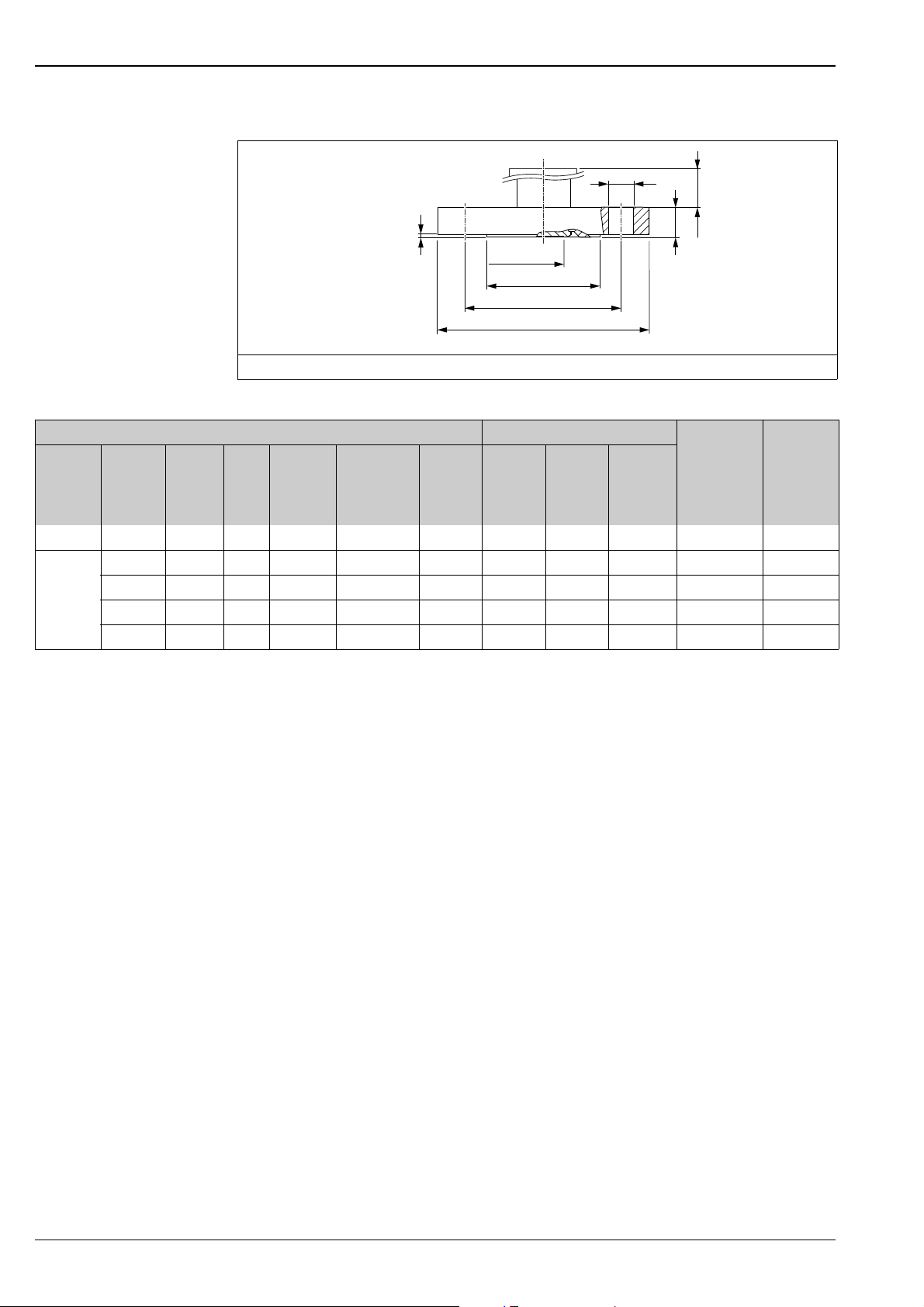
Deltapilot M FMB50/51/52/53
D
k
f
g
2
g
b
41
d=Mø35.8
Process connections FMB50, FMB51, FMB52 - continued
1)
Flange
Material Nominal
diameter
40 A 10 K 140 16 81 2 4 19 105 2.55 (5.62) KEJ
AISI 316L
(1.4435)
50 A 10 K 155 16 96 2 4 19 120 2.95 (6.50) KFJ
80 A 10 K 185 18 126 2 8 19 150 4.25 (9.37) KGJ
100 A 10 K 210 18 151 2 8 19 175 5.35 (11.79) KHJ
Nominal
pressure
JIS flanges, connection dimensions as per JIS B 2220 BL, raised face RF
Engineering unit mm
Boltholes Weight Option
D Thickness Diameter of
raised face
b g f g
[mm] [mm] [mm] [mm] [mm] [mm] [kg (lbs)]
Height of
raised
face
Quantity Diameter Hole circle
2
k
A0020004
2)
1) The roughness of the surface in contact with the medium, including the sealing surface of the flanges (all standards), is < R
Lower surface roughness available on request.
2) Product Configurator, “Process connection” section
0.8 μm (31.5 μin).
a
40 Endress+Hauser
Page 41

Deltapilot M FMB50/51/52/53
ø43.5 (1.71)
68.5 (2.7)
1
2
ø43.5 (1.71)
179.5 (7.07)
1
2
78 (3.07)
ø2"
ø3"
1
2
188 (7.4)
ø3"
ø2"
1
2
Process connections FMB50 continued
A
Engineering unit mm (in)
1)
Item
A
B
Designation Material Approval Weight kg (lbs) Option
Universal process adapter incl. silicone molded seal
(spare part no.: 52023572) FDA 21CFR177.2600/USP Class VI-70C
Universal process adapter incl. EPDM molded seal
(order no.: 71100719) EPDM-70, FDA, USP Class VI; (5 pieces)
Universal process adapter, 6 inch extension incl. silicone molded seal
(spare part no.: 52023572) FDA 21CFR177.2600/USP Class VI-70C
Universal process adapter, 6 inch extension incl. EPDM molded seal
(order no.: 71100719) EPDM-70, FDA, USP Class VI; (5 pieces)
Universal adapter
A0026355
B
A0020014
2)
•1: top section
AISI 316L
(1.4404)
EHEDG, 3A
0.8 (1.76)
EHEDG, 3A UNJ
UPJ
3)
)
•2: bottom
section
AISI 316L
(1.4435)
EHEDG, 3A
EHEDG, 3A UOJ
1.7 (3.75)
UQJ
)
)
1) Surface roughness of the surfaces in contact with the medium Ra 0.76μm (30 μin) as standard. Surface roughness Ra<0.38 μm electropolished
(wetted) Ordering information: Product Configurator, "Service" ordering feature, option "HK".
2) Product Configurator, “Process connection” section
3) Endress+Hauser supplies these slotted nuts in stainless steel AISI 304 (1.4301) or in AISI 304L (1.4307).
Anderson process adapter
Item
A
B
A
Engineering unit mm (in)
1)
Designation Material Approval Weight kg (lbs) Option
Short Anderson process adapter, 2-3/16", 316L,
incl. silicone molded seal FDA 21CFR177.2600
Long Anderson process adapter, 6-1/2", 316L,
incl. silicone molded seal FDA 21CFR177.2600
• 1: top section AISI 316L (1.4404)
• 2: bottom section AISI 316L
(1.4435)
• Slotted nut AISI 316L (1.4404)
B
A0020015
3A 1.5 (3.31) USJ
3A 2.9 (6.39) UTJ
1) Surface roughness of the surfaces in contact with the medium R
2) Product Configurator, “Process connection” section
Endress+Hauser 41
0.76μm (30 μin) as standard. Lower surface roughness available on request.
a
A0020016
2)
Page 42
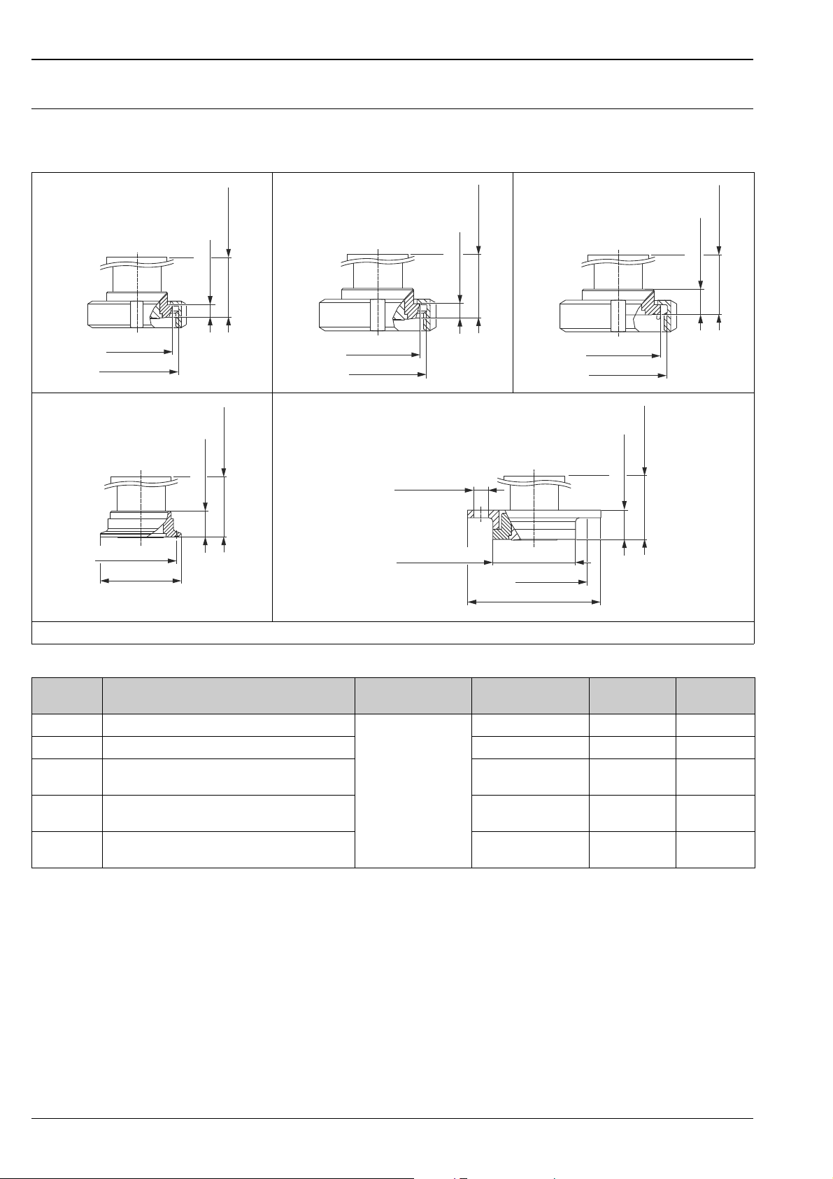
Deltapilot M FMB50/51/52/53
Rd 65 x 1/6
59.5 (2.34)
ø56 (2.2)
10.2 (0.4)
Rd 78 x 1/6
ø68.5 (2.7)
11.2 (0.44)
59.5 (2.34)
Rd 78 x 1/6
ø68.5 (2.7)
20.5 (0.81)
59.5 (2.34)
ø64 (2.52)
20.5 (0.81)
ø56.5 (2.22)
59.5 (2.34)
4 x
ø11.5 (0.45)
23.5 (0.93)
ø84 (3.31)
ø105 (4.13)
ø65 (2.56 )
-1.2 -0.05
59.5 (2.34)
Process connections FMB50 continued
A
D
Hygienic connections
B
A0020005
E
A0020006
C
A0020007
A0020008
Engineering unit mm (in)
1)
Item
Designation Material Approval Weight
Option
kg (lbs)
A DIN 11851 DN 40 PN 25
EHEDG, 3A 0.7 (1.54) MZJ
B DIN 11851 DN 50 PN 25 EHEDG, 3A 0.9 (1.98) MRJ
C
DIN11864-1 A DN50 PN16 pipe DIN11866-A,
slotted nut, 316L
D Tri-Clamp ISO 2852 DN 40 – DN 51 (2"),
AISI 316L (1.4435)
EHEDG, 3A 1 (2.21) NDJ
EHEDG, 3A 0.7 (1.54) TDJ
3)
)
)
)
DIN 32676 DN 50
E DRD DN 50 (65 mm) PN 25,
- 1.1 (1.98) TIJ
slotted nut AISI 304 (1.4301)
1) Surface roughness of the surfaces in contact with the medium R
0.76μm (30 μin) as standard. Lower surface roughness available on request.
a
2) Product Configurator, “Process connection” section
3) Endress+Hauser supplies these slotted nuts in stainless steel AISI 304 (DIN/EN material number 1.4301) or in AISI 304L (DIN/EN material
number 1.4307).
A0020009
2)
42 Endress+Hauser
Page 43
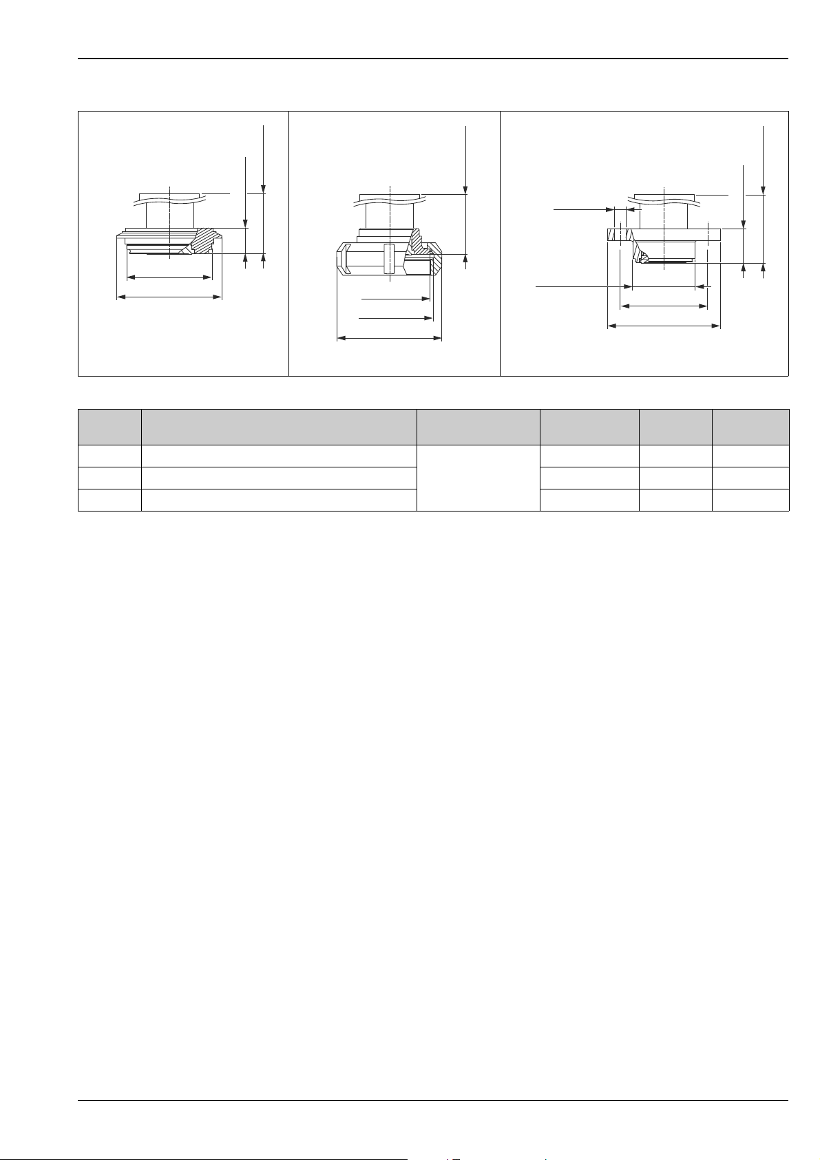
Deltapilot M FMB50/51/52/53
ø84 (3.31)
ø68 (2.68)
20.5 (0.81)
59.5 (2.34)
Rd 70 x 1/6
ø65 (2.56)
ø84 (3.31)
59.5 (2.34)
ø9 (0.35)
27 (1.06)
ø90 (3.54)
ø70 (2.76)
ø49.9 (1.96)
59.5 (2.34)
F
Engineering unit mm (in)
1)
Item
Designation Material Approval Weight
A0020010
G
Engineering unit mm (in)
H
A0020011
Engineering unit mm (in)
Option
kg (lbs)
F Varivent Type N for pipes 40 – 162, PN 40
G SMS 2", PN 25 EHEDG, 3A 0.7 (1.54) TXJ
AISI 316L (1.4435)
EHEDG, 3A 1 (2.21) TRJ
H NEUMO, D50, PN 16, 316L 3A 0.8 (1.76) S4J
A0020012
2)
3)
1) Surface roughness of the surfaces in contact with the medium R
0.76μm (30 μin) as standard. Lower surface roughness available on request.
a
2) Product Configurator, “Process connection” section
3) Endress+Hauser supplies these slotted nuts in stainless steel AISI 304 (DIN/EN material number 1.4301) or in AISI 304L
(DIN/EN material number 1.4307).
Endress+Hauser 43
Page 44

Deltapilot M FMB50/51/52/53
ø21,3 (0.84)
ø42,4 (1.67)
ø43,5 (1.71)
208 (8.19)
L
H
Process connections FMB51 (rod version)
Threaded connection ISO 228 and NPT
H For dimensions of process connections
L Probe length L = 0.4 m to 4 m (1.3 ft to 13 ft) - see Product Configurator, “Probe connection” section
Engineering unit mm (in)
ä
36 ff
A0023592
Process connection incl. sensor Weight
Housing weight ä 36 ff
Process connection weight ä 37 ff
Pipe incl. cable 0.77 kg/m (1.70 lbs/3.3 ft)
Threaded connection incl. measuring cell tube and sensor 1.65 kg (3.64 lbs)
Flange connection incl. measuring cell tube and sensor, without a flange -
Total weight of device
44 Endress+Hauser
Page 45
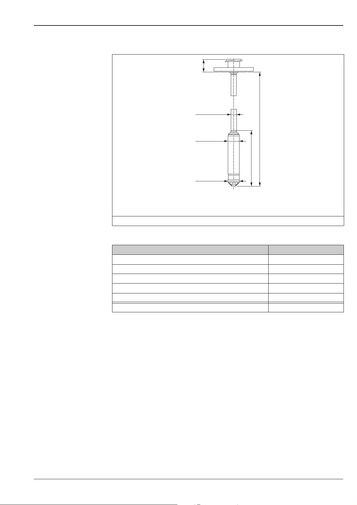
Deltapilot M FMB50/51/52/53
ø21,3 (0.84)
ø42,4 (1.67)
ø43,5 (1.71)
208 (8.19)
L
H
EN/DIN, ANSI and JIS flanges
A0023593
H For dimensions of process connections
L Probe length L = 0.4 m to 4 m (1.3 ft to 13 ft) - see Product Configurator, “Probe connection” section
Engineering unit mm (in)
Process connection incl. sensor Weight
Housing weight ä 36 ff
Process connection weight ä 37 ff
Pipe incl. cable 0.77 kg/m (1.70 lbs/3.3 ft)
Threaded connection incl. measuring cell tube and sensor -
Flange connection incl. measuring cell tube and sensor, without a flange 1.3 kg (2.87 lbs)
Total weight of device
ä
36 ff
Endress+Hauser 45
Page 46
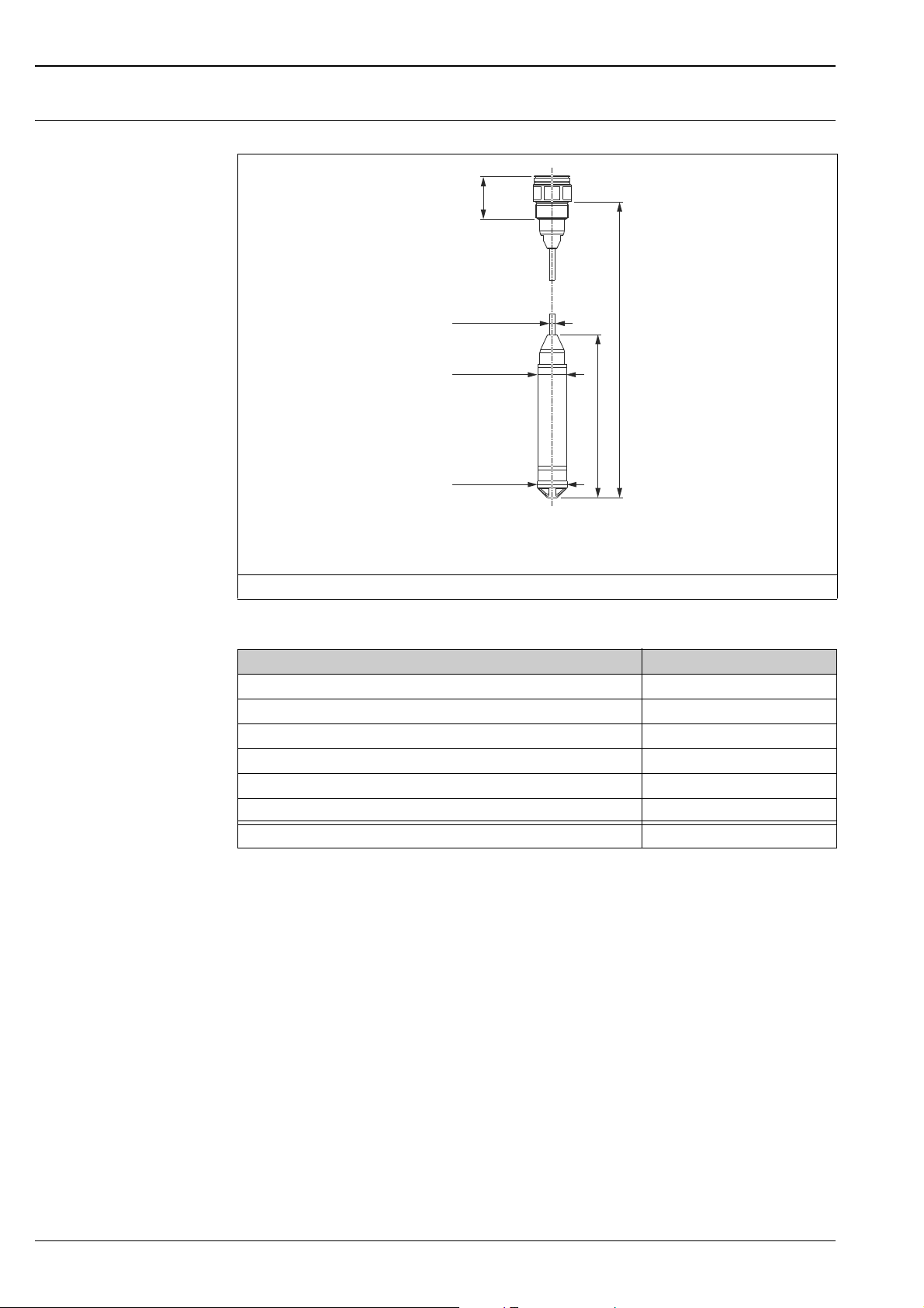
Deltapilot M FMB50/51/52/53
ø10,4 (0.41)
ø42,4 (1.67)
ø43,5 (1.71)
236 (9.29)
L
H
Process connections FMB52 (cable version)
Threaded connection ISO 228 and NPT
H For dimensions of process connections
L Probe length L = 0.5 to 400 m (1.6 to 1312 ft) - see Product Configurator, “Probe connection” section
Engineering unit mm (in)
ä
36 ff
A0023594
Process connection incl. sensor Weight
Housing weight ä 36 ff
Process connection weight ä 37 ff
PE cable 0.13 kg/m (0.28 lbs/3.3 ft)
FEP cable 0.18 kg/m (0.40 lbs/3.3 ft)
Threaded connection incl. measuring cell tube and sensor 1.65 kg (3.64 lbs)
Flange connection incl. measuring cell tube and sensor, without a flange -
Total weight of device
46 Endress+Hauser
Page 47
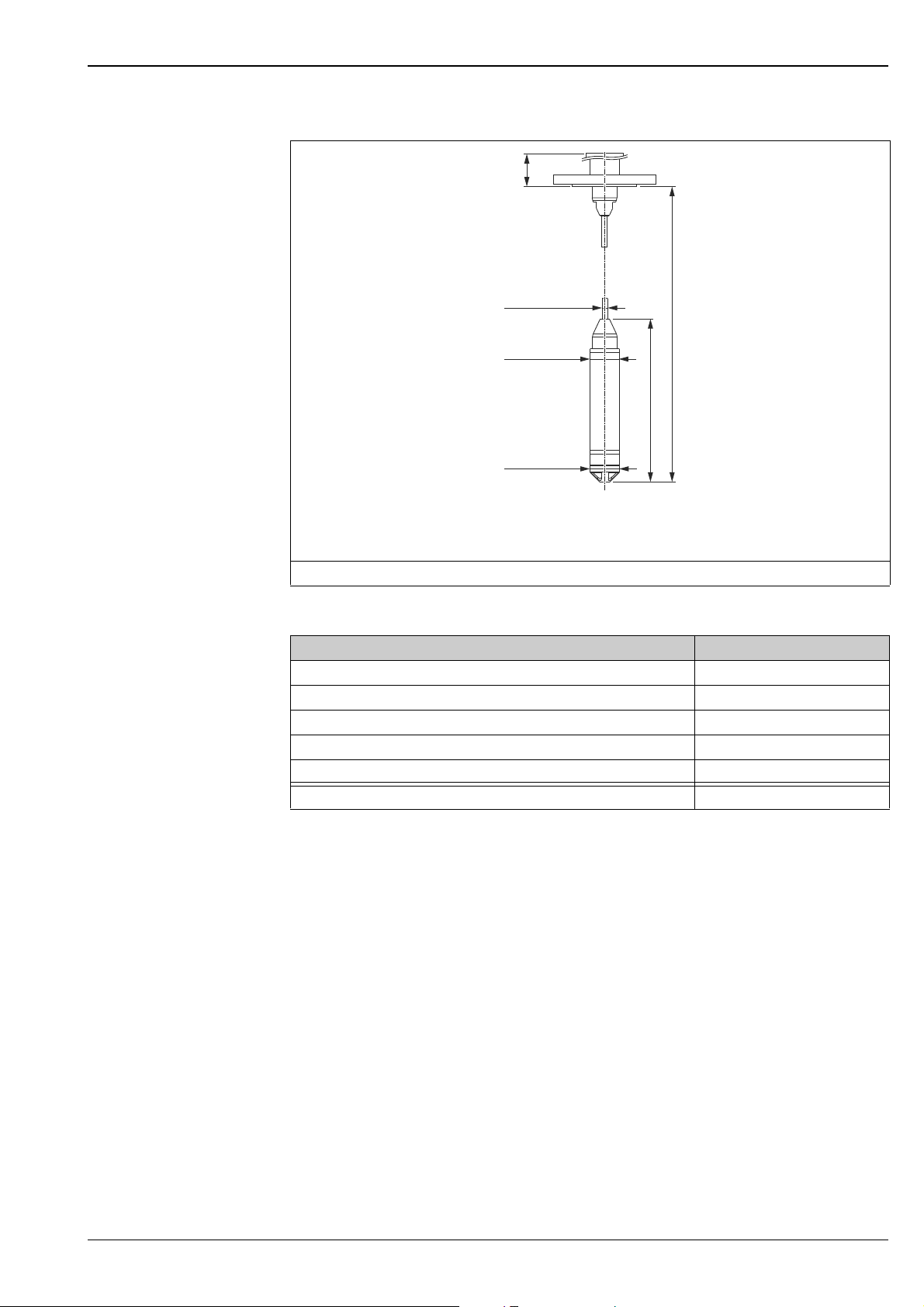
Deltapilot M FMB50/51/52/53
H
ø10,4 (0.41)
ø42,4 (1.67)
ø43,5 (1.71)
236 (9.29)
L
EN/DIN, ANSI and JIS flanges
A0023597
H For dimensions of process connections
L Probe length L = 0.5 to 400 m (1.6 to 1312 ft) - see Product Configurator, “Probe connection” section
Engineering unit mm (in)
Process connection incl. sensor Weight
Housing weight ä 36 ff
Process connection weight ä 37 ff
PE cable 0.13 kg/m (0.28 lbs/3.3 ft)
FEP cable 0.18 kg/m (0.40 lbs/3.3 ft)
Flange connection incl. measuring cell tube and sensor, without a flange 1.3 kg (2.87 lbs)
Total weight of device
ä
36 ff
Endress+Hauser 47
Page 48

Dimensions of FMB53 with
ø10,4 (0.41)
ø42,4 (1.67)
ø43,5 (1.71)
236 (9.29)
L
238 (9.37)
169 (6.65)
137 (5.39)
156 (6.14)
194 (7.64)
222 (8.74)
235 (9.25)
5
33
4
ø61 (2.4)
11
22
181 (7.13)
R 200 (7.87)
³
F31 housing, suspension
clamp and mounting bracket
Deltapilot M FMB50/51/52/53
FMB53 with suspension clamp and mounting bracket (mounting bracket without marine approval)
1 Dimensions for housing covers with a viewing window.
2 Housing covers without a viewing window are approx. 15 mm (0.59 in) lower.
3 Mounting bracket for pipe and wall mounting (for pipes from 1 ¼" up to 2" diameter)
4 Suspension clamp
5 Measuring cell tube
L Probe length = 0.5 to 400 m (1.6 to 1312 ft) - see Product Configurator, “Probe connection” section
Engineering unit mm (in)
Process connection incl. sensor Weight
Housing weight ä 36 ff
PE cable (cable length > 120 m (394 ft) = Delivery on cable reel) 0.13 kg/m (0.28 lbs/3.3 ft)
FEP cable (cable length > 120 m (394 ft) = Delivery on cable reel) 0.18 kg/m (0.40 lbs/3.3 ft)
Mounting bracket 0.2 kg (0.44 lbs)
Pipe bend incl. cable entry 0.65 kg (1.43 lbs)
Suspension clamp 0.4 kg (0.88 lbs)
Measuring cell tube incl. sensor 1.0 kg (2.21 lbs)
Total weight of device
A0023598
48 Endress+Hauser
Page 49
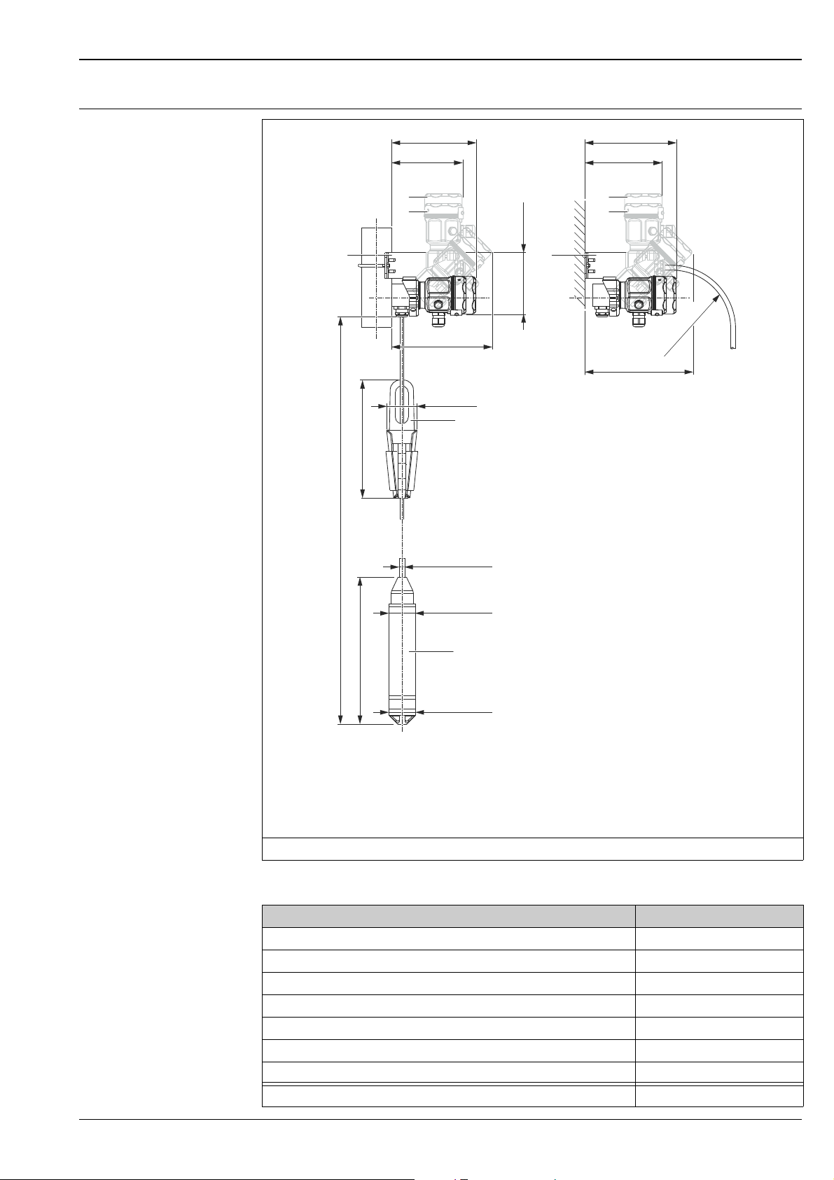
Deltapilot M FMB50/51/52/53
ø10,4 (0.41)
ø42,4 (1.67)
ø43,5 (1.71)
236 (9.29)
L
238 (9.37)
159 (6.26)
127 (5)
146 (5.75)
187 (7.36)
211 (8.31)
224 (8.82)
5
33
4
ø61 (2.4)
174 (6.85)
1
2
1
2
R 200 (7.87)
³
Dimensions of FMB53 with F15 housing, suspension clamp and mounting bracket
FMB53 with suspension clamp and mounting bracket (mounting bracket without marine approval)
1 Dimensions for housing covers with a viewing window.
2 Housing covers without a viewing window are approx. 15 mm (0.59 in) lower.
3 Mounting bracket for pipe and wall mounting (for pipes from 1 ¼" up to 2" diameter)
4 Suspension clamp
5 Measuring cell tube
L Probe length = 0.5 to 400 m (1.6 to 1312 ft) - see Product Configurator, “Probe connection” section
Engineering unit mm (in)
Process connection incl. sensor Weight
Housing weight ä 36 ff
PE cable (cable length > 120 m (394 ft) = Delivery on cable reel) 0.13 kg/m (0.28 lbs/3.3 ft)
FEP cable (cable length > 120 m (394 ft) = Delivery on cable reel) 0.18 kg/m (0.40 lbs/3.3 ft)
Mounting bracket 0.2 kg (0.44 lbs)
Pipe bend incl. cable entry 0.65 kg (1.43 lbs)
Suspension clamp 0.4 kg (0.88 lbs)
Measuring cell tube incl. sensor 1.0 kg (2.21 lbs)
Total weight of device
A0023600
Endress+Hauser 49
Page 50
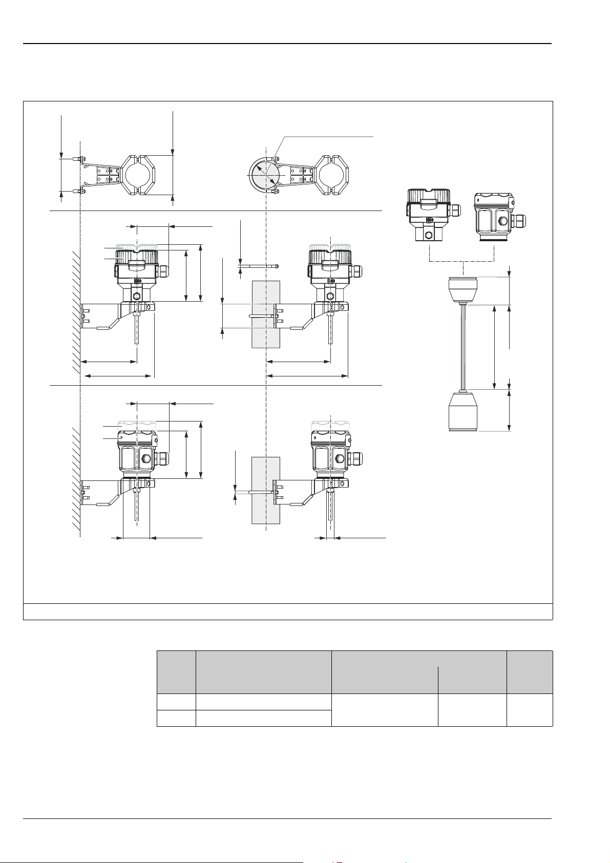
Wall and pipe mounting with
63 (2.48)
L1
50 (1.97)
L
122 (4.8)
52 (2.05)
86 (3.39)
70 (2.76)
140 (5.51)
158 (6.22)
175 (6.89)
A
B
ø52 (2.05) ø20 (0.79)
6 (0.24)
ø6 (0.24)
ø42...60 (1.65...2.36)
1
2
95 (3.74)
114 (4.49)
112 (4.4)
127 (5)
69 (2.72)
1
2
"Separate housing" version
Deltapilot M FMB50/51/52/53
1 Housing cover with viewing window.
2 Housing cover without viewing window
L PE cable 2 m (6.6 ft), 5 m (16 ft) or 10 m (33 ft). FEP cable 5 m (16 ft)
L1 FMB50 = 91 mm (3.58 in); FMB51 and FMB52 = 81 mm (3.19 in)
Engineering unit mm (in)
Item Designation Weight Option
A Dimensions with F31 housing
B Dimensions with F15 housing
1) Product Configurator, "Separate housing" ordering feature
Also available for order as a separate accessory: part number 71102216
Housing (F31 or F15) Mounting
ä 36 ff 0.5 kg (1.10) U
bracket
A0025834
1)
50 Endress+Hauser
Page 51
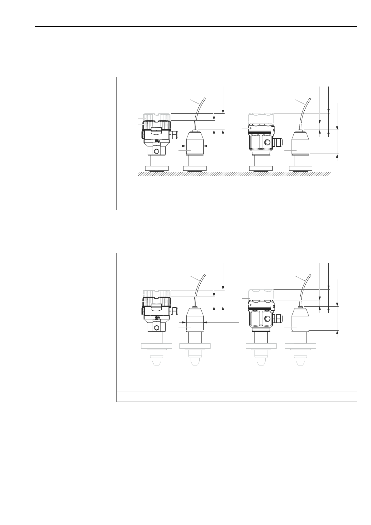
Deltapilot M FMB50/51/52/53
91 (3.58)
F31
F15
1
ø54.1 (2.13)
r ³120 (4.72) r³ 120 (4.72)
1
1
2
2
19 (0.75)
34 (1.34)
7 (0.28)
26 (1.02)
1
81 (3.19)
F31
F15
1
ø54.1 (2.13)
r ³120 (4.72) r³ 120 (4.72)
1
1
2
2
29 (1.14)
44 (1.73)
17 (0.67)
36 (1.42)
1
FMB50: Reduction in installation height
If the separate housing is used, the mounting height of the process connection is reduced compared to
the dimensions of the standard version.
A0025833
1 Process connection adapter
Engineering unit mm (in)
FMB51, FMB52: Reduction in installation height
If the separate housing is used, the mounting height of the process connection is reduced compared to
the dimensions of the standard version.
A0025827
1 Process connection adapter
Engineering unit mm (in)
Endress+Hauser 51
Page 52

Example for a "Separate housing" version
121,7 (4.79)
L1
R20 (4.72)
³1
L
ø54.1 (2.13)
3
1
2
Deltapilot M FMB50/51/52/53
A0023603
Connecting cable with process connection adapter and mounting bracket, here shown with an FMB52
1 Mounting bracket for pipe and wall mounting (for pipes from 1 1/4" up to 2" diameter)
2 Process connection adapter
3 Measuring cell tube
L1 PE cable = 2 m (6.6 ft), 5m (16 ft) or 10 m (33 ft)
FEP cable = 5 m (16 ft)
L Probe length = 0.5 to 400 m (1.6 to 1312 ft)
Engineering unit mm (in)
Process connection incl. sensor Weight
Separate housing for FMB50 Weight of housing ( ä 36 ff) + 0.5 kg (1.10 lbs)
Separate housing for FMB51 and FMB52 Weight of housing ( ä 36 ff) + 0.65 kg (1.43 lbs)
Process connection adapter 0.4 kg (0.88 lbs)
Mounting bracket 0.2 kg (0.44 lbs)
Pipe bend incl. cable entry 0.65 kg (1.43 lbs)
PE cable 2 m (6.6 ft) 0.16 kg (0.35 lbs)
PE cable 5 m (16 ft) 0.32 kg (0.71 lbs)
Total weight of device
Ordering information for FMB50, FMB51, FMB52: Product Configurator, "Separate housing" ordering
feature
52 Endress+Hauser
Page 53

Deltapilot M FMB50/51/52/53
114 15 16
4
10
711
12
5
3
2
6
9
8
13
Materials not in contact with process
F31 housing
Front view, left-hand side view, top view
Item
number
1
2
3Cover seal EPDM
4 Sight glass Mineral glass
5 Sight glass seal Silicone (VMQ)
6 External ground terminal AISI 304 (1.4301)
7 Nameplates Plastic film
8 Attachment for tie-on label AISI 304 (1.4301)/ AISI 316 (1.4401)
9 Pressure compensation filter AISI 316L (1.4404) and PBT-FR
10 Pressure compensation filter, O-ring VMQ or EPDM
11 Sealing ring EPDM
12 Snap ring PC Plastic
13 Seal of cable gland and blind plug EPDM/NBR
14
15 Blind plug PBT-GF30 FR
16 Cover clamp Clamp AISI 316L (1.4435), screw A4
Component part Material
F31 housing, RAL 5012 (blue) Die-cast aluminum with protective powder-coating
on polyester base
Cover, RAL 7035 (gray) Die-cast aluminum with protective powder-coating
on polyester base
Cable gland Polyamide (PA), for dust ignition-proof: CuZn nickel-
plated
for dust ignition-proof, Ex d, FM XP and CSA XP:
AISI 316L (1.4435)
A0023615
Endress+Hauser 53
Page 54

F15 housing
114
9101213
4
5
8
3
6
11
7
2
Front view, left-hand side view, top view
Deltapilot M FMB50/51/52/53
A0023616
Item
number
1F15 housing
2Cover
3Cover seal Silicone with PTFE coating
4 Sight glass for non-hazardous area, ATEX Ex
4 Sight glass for ATEX 1/2 D, ATEX 1/3 D,
5 Sight glass seal Silicone (VMQ)
6 External ground terminal AISI 304 (1.4301)
7 Attachment for tie-on label AISI 304 (1.4301)/ AISI 316 (1.4401)
8 Pressure compensation filter AISI 316L (1.4404) and PBT-FR
9 Pressure compensation filter, O-ring VMQ or EPDM
10 Nameplates lasered
11 Cable gland Polyamide (PA), for dust ignition-proof: CuZn
12 Seal of cable gland and blind plug NBR/Silicone/EPDM
13 Sealing ring EPDM
14 Screw A4-50
Component part Material
AISI 316L (1.4404)
ia, NEPSI Zone 0/1 Ex ia, IECEx Zone 0/1 Ex
ia, FM NI, FM IS, CSA IS
ATEX 1 GD, ATEX 1/2 GD, ATEX 3 G, FM DIP,
CSA dust ignition-proof
Polycarbonate (PC)
Mineral glass
nickel-plated
54 Endress+Hauser
Page 55
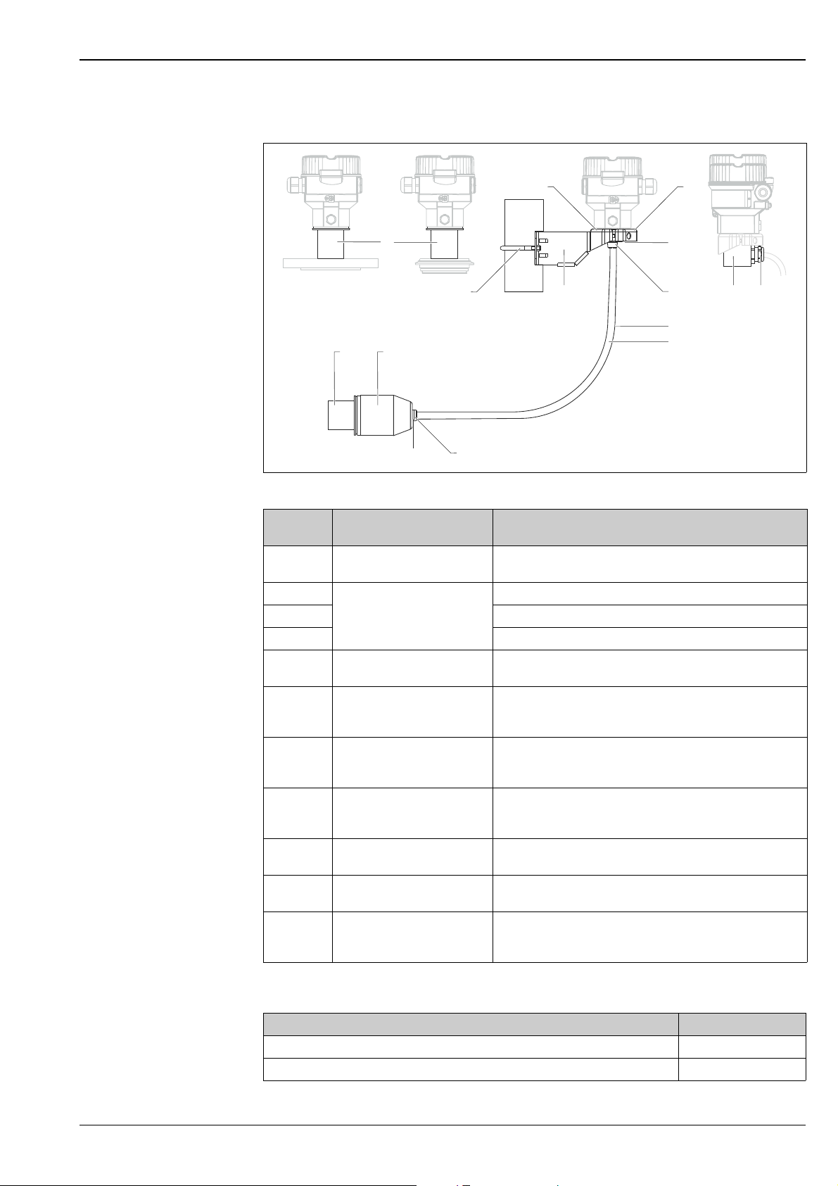
Deltapilot M FMB50/51/52/53
1
5
23
4
4
6
6
1 9
10511
7
8
1
5
23
4
4
6
6
1 9
10511
7
8
Connecting parts
A0023617
Item
number
1 Connection between the
2 Mounting bracket Bracket AISI 316L (1.4404)
3Screw and nuts A4-70
4 Half-shells: AISI 316L (1.4404)
5 Seal for cable from
6 Gland for cable from separate
7 PE cable for separate housing Abrasion-proof cable with strain-relief Dynema members;
8 FEP cable for separate housing Abrasion-proof cable; shielded using galvanized steel wire
9 Process connection adapter for
10 Housing adapter FMB50, FMB51, FMB52: AISI 316L (1.4404)
11 Cable gland:
Component part Material
AISI 316L (1.4404)
housing and process connection
Separate housing
housing:
Screws:
separate housing
Sealing insert:
O-ring:
FKM, EPDM
AISI 316L (1.4404)
A2
shielded using aluminum-coated film; insulated with
polyethylene (PE-LD), black; copper wires, twisted, UV-resistant
netting; insulated with fluorinated ethylene propylene (FEP),
black; copper wires, twisted, UV-resistant
AISI 316L (1.4404)
FMB53: AISI 304 (1.4301)
CuZn nickel-plated
TPE-V
NBR
Fill fluid
1)
Designation Option
Inert oil 2
Synthetic oil polyalphaolefin FDA 21 CFR 178.3570, NSF H1 3
1) Product Configurator, “Fill fluid” section
Endress+Hauser 55
Page 56
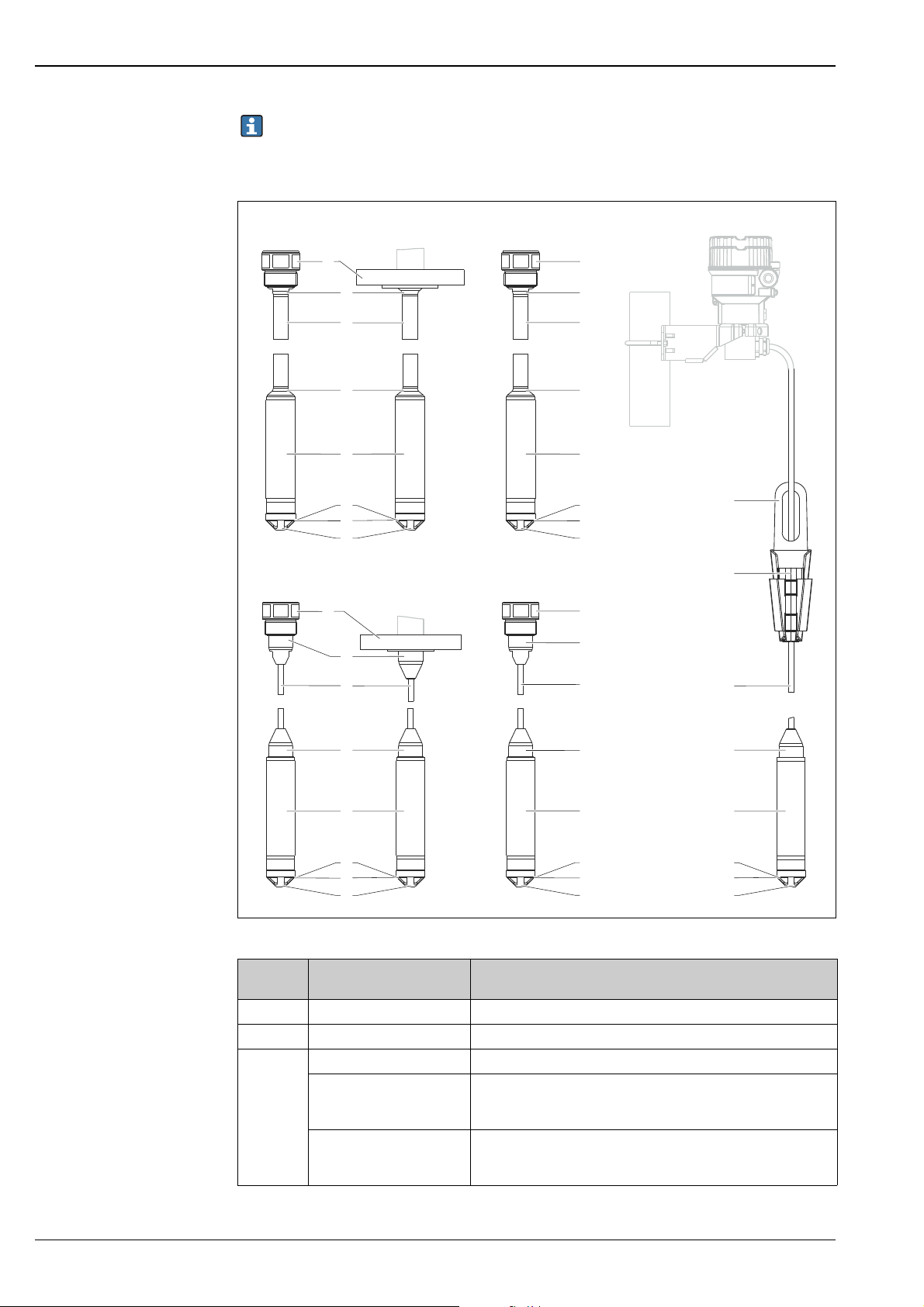
Deltapilot M FMB50/51/52/53
1
2
3
4
5
6
7
8
1
2
3
4
5
6
7
8
FMB51 FMB53
FMB52
ISO228 Version „GGC“
ISO228 Version „GGC“
9
10
11
12
13
14
15
8
11
12
13
14
15
8
10
9
3
4
5
6
7
8
17
16
Materials in contact with the process
The wetted device components are listed in the "Mechanical construction" ( ä 36 ff) and "Ordering
information" ( ä 67 ff) sections.
Item
number
1 Process connection ä 36 ff
2 Socket AISI 316L (1.4404)
3 Rod AISI 316L (1.4435)
A0023619
Component part Material
PE cable Abrasion-proof cable; shielded using galvanized steel wire netting
PE cable
(Usage in drinking water)
and aluminum-coated film; insulated with polyethylene (PE-LD),
black/blue; copper wires, twisted, UV-resistant
Abrasion-proof cable; shielded using galvanized steel wire netting
and aluminum-coated film; insulated with polyethylene (PE-LD),
black; copper wires, twisted, UV-resistant
56 Endress+Hauser
Page 57
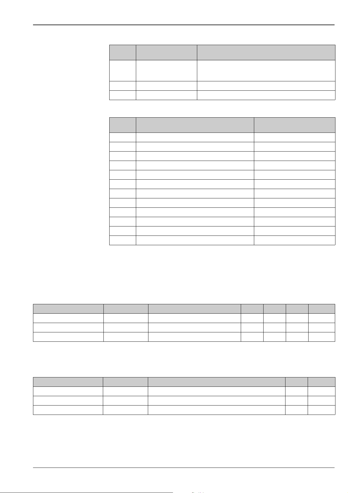
Deltapilot M FMB50/51/52/53
Item
number
3 FEP cable Abrasion-proof cable; shielded using galvanized steel wire netting
4 Socket AISI 316L (1.4404)
5 Probe tube AISI 316L (1.4404)
Item
number
6 Process isolating diaphragm and meter body ä 67 ff
7Seals ä 67 ff
8 Protection cap POM
9 Process connection Alloy C276 (2.4819)
10 Socket Alloy C4 (2.4610)
11 Rod Alloy C4 (2.4610)
12 Socket Alloy C4 (2.4610)
13 Probe tube Alloy C22 (2.4602)
14 Process isolating diaphragm and meter body ä 67 ff
15 Seals ä 67 ff
16 Suspension clamp AISI 316L (1.4404)
17 Clamping jaw PA-GF
Component part Material
and aluminum-coated film; insulated with fluorinated ethylene
propylene (FEP), black; copper wires, twisted, UV-resistant
Component part Material
DIN/EN flanges
Endress+Hauser supplies DIN/EN flanges made of stainless steel AISI 316L as per material numbers
1.4435 or 1.4404. With regard to their stability-temperature property, the materials 1.4435 and
1.4404 are grouped together under 13EO in EN 1092-1 Tab. 18. The chemical composition of the two
materials can be identical.
Process isolating diaphragm
Process isolating diaphragm Coating Meter body FMB50 FMB51 FMB52 Option
Alloy C276 (2.4819) - 316L (1.4435) or Alloy C276 (2.4819)
Alloy C276 (2.4819) Gold>Rhodium Alloy C276 (2.4819) L
Alloy C276 (2.4819) Gold>Platin Alloy C276 (2.4819) ―N
1) Product Configurator, "Material of process isolating diaphragm" ordering feature
2) The material of the meter body corresponds to the material of the process connection.
Process isolating diaphragm Coating Meter body FMB53 Option
Alloy C276 (2.4819) - 316L (1.4435) B
Alloy C276 (2.4819) Gold>Rhodium Alloy C276 (2.4819) L
Alloy C276 (2.4819) Gold>Platin Alloy C276 (2.4819) N
1) Product Configurator, "Material of process isolating diaphragm" ordering feature
2)
B
1)
1)
Endress+Hauser 57
Page 58

Deltapilot M FMB50/51/52/53
Seals
Designation Option
FKM Viton A
EPDM J
Kalrez 6375 L
None, welded cell U
1) Product Configurator, "Seal" ordering feature
2) Not FMB50
1)
2)
)
)
TSE Certificate of Suitability (Transmissible Spongiform Encephalopathy)
The following applies to all process wetted device components:
• They do not contain any materials derived from animals.
• No auxiliaries or operating materials derived from animals are used in production or processing.
58 Endress+Hauser
Page 59

Deltapilot M FMB50/51/52/53
1
3
2
4
5
E
+
–
Operability
Operating concept Operator-oriented menu structure for user-specific tasks
• Commissioning
•Operation
•Diagnostics
•Expert level
Quick and safe commissioning
Guided menus for applications
Reliable operation
• Onsite operation possible in several languages
• Standardized operation at the device and in the operating tools
• Parameters relating to measured values can be locked/unlocked using the device's write protection
switch, using the device software or via remote control.
Efficient diagnostics increase measurement availability
• Remedial measures are integrated in plain text
• Diverse simulation options
Onsite operation Local display (optional)
A 4-line liquid crystal display (LCD) is used for display and operation. The local display shows measured
values, dialog texts as well as fault and notice messages in plain text, thereby supporting the user at
every stage of operation. The liquid crystal display of the device can be turned in 90° stages. Depending
on the orientation of the device, this makes it easy to operate the device and read the measured values.
Functions:
• 8-digit measured value display including sign and decimal point, bar graph for 4 to 20 mA HART as
current display; or for PROFIBUS PA as graphic display of the standardized value of the AI Block; for
FOUNDATION Fieldbus as graphic display of the transducer output in relation to the set pressure
range.
• Simple and complete menu guidance as parameters are split into several levels and groups
• Each parameter is given a 3-digit ID number for easy navigation
• Possibility of configuring the display to suit individual requirements and preferences, such as
language, alternating display, contrast setting, display of other measured values such as sensor
temperature etc.
• Comprehensive diagnostic functions (fault and warning message etc.)
1Operating keys
2Bar graph
3Symbol
4Header
5 Parameter ID number
Ordering information:
Product Configurator, "Output; operation" ordering feature
Endress+Hauser 59
A0016498
Page 60
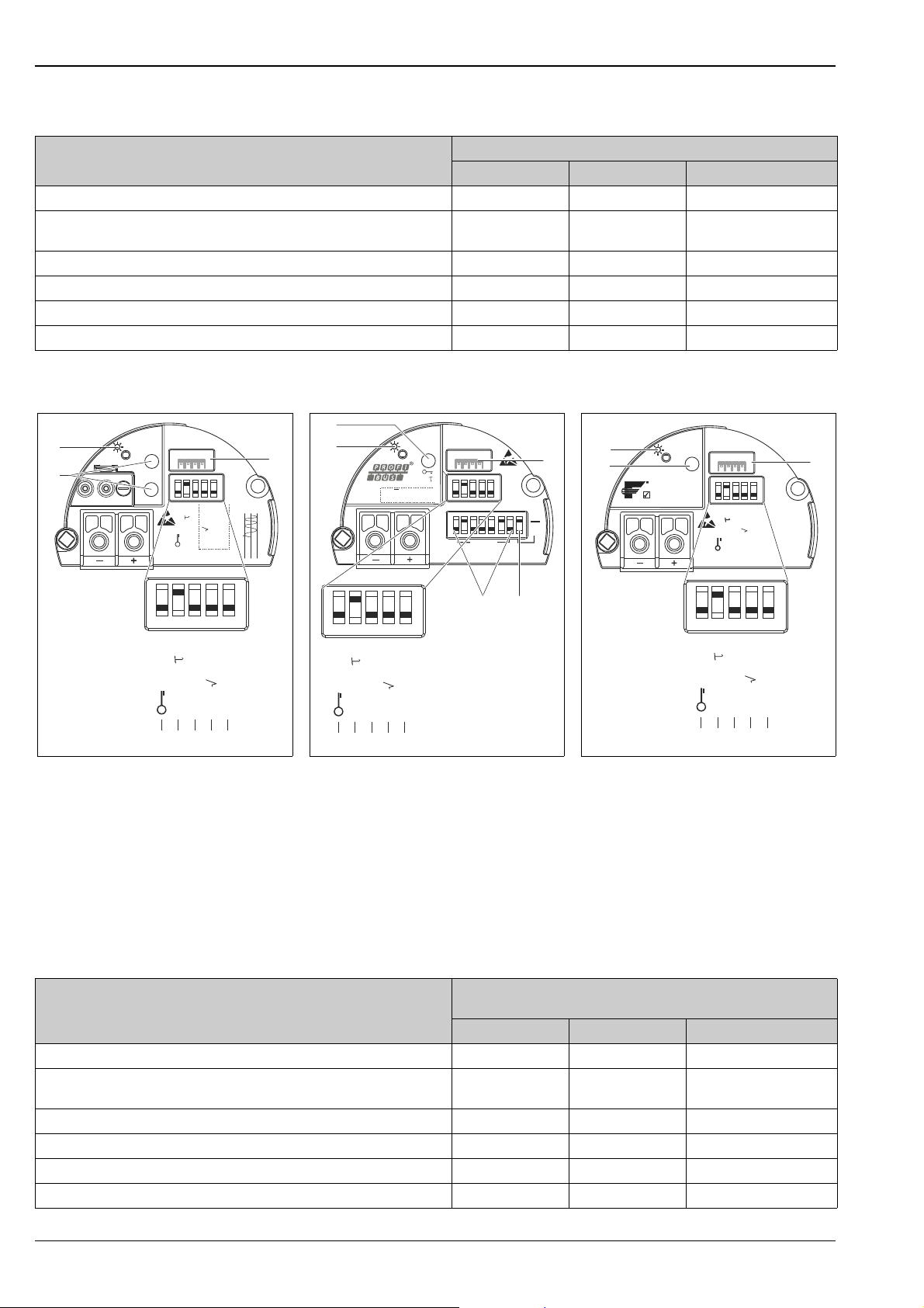
Deltapilot M FMB50/51/52/53
on
off
SW / P2=High
SW / Alarm min
SW /
damping
1
2
345
on
off
Display
Zero
Span
HAR T
R
FIELD C OMMUN ICAT ION P R OTO CO L
SW / P2=High
delta p only
SW / Alarm min
SW /
damping
87654
3
1
2
10 9876
on
off
SW / P2=High
damping
1
2
345
on:P2=
delta p
only
High off:SW
1
2
3
4
5
off:SW
on:
Ö
on
off
damp
not used
Address
SW
HW
Zero
on
off
Display
SW /
1
3
45
2
on
off
SW / P2=High
Simulation
SW /
damping
1
2
345
on
off
Display
Zero
simulation
TM
F
OUNDATION
SW / P2=High
SW /
damping
delta p only
87654
1
2
3
Function Operation via display
HART PROFIBUS PA FOUNDATION Fieldbus
Position adjustment (zero point correction)
Setting lower range value and upper range value - reference pressure present
at the device
Device reset
Locking and unlocking parameters relevant to the measured value
Value acceptance indicated by the green LED ―― ―
Switching damping on and off
Operating keys and elements located on the electronic insert
A0023125
HART electronic insert
1 Operating keys for lower range value (zero) and
upper range value (span)
2 Green LED to indicate successful operation
3 Slot for optional local display
4 DIP switch only for Deltabar M
5 DIP switch only for Deltabar M
6 DIP switch for alarm current SW / Alarm Min
(3.6 mA)
7 DIP switch for switching damping on/off
8 DIP switch for locking/unlocking parameters
relevant to the measured value
Function Operation with operating keys and elements on the
Position adjustment (zero point correction)
Setting lower range value and upper range value - reference pressure present
at the device
Device reset
Locking and unlocking parameters relevant to the measured value
Value acceptance indicated by the green LED
Switching damping on and off
PROFIBUS PA electronic insert
1 Green LED to indicate successful operation
2 Operating key for position zero adjustment or
reset (Zero)
3 Slot for optional local display
4 DIP switch for bus address SW / HW
5DIP switch for hardware address
6 DIP switch only for Deltabar M
7 DIP switch only for Deltabar M
8Not used
9 DIP switch for switching damping on/off
10 DIP switch for locking/unlocking parameters
relevant to the measured value
A0023126
FOUNDATION Fieldbus electronic insert
1 Operating key for position zero adjustment or
reset (Zero)
2 Green LED to indicate successful operation
3 Slot for optional local display
4 DIP switch only for Deltabar M
5 DIP switch only for Deltabar M
6 DIP switch for simulation mode
7 DIP switch for switching damping on/off
8 DIP switch for locking/unlocking parameters
relevant to the measured value
electronic insert
HART PROFIBUS PA FOUNDATION Fieldbus
― ―
A0023127
60 Endress+Hauser
Page 61
Deltapilot M FMB50/51/52/53
Ordering information:
Product Configurator, "Display, operation" ordering feature
Operating languages You can also choose another language in addition to the standard language "English":
Designation Option 1)
English AA
German AB
French AC
Spanish AD
Italian AE
Dutch AF
Chinese AK
Japanese AL
1) Product Configurator, "Additional operating language" ordering
feature
Remote operation All software parameters are accessible depending on the position of the write protection switch on the
device.
Hardware and software for remote
operation
FieldCare ä 61 ff
FieldXpert SFX100 ä 61 ff ―
NI-FBUS Configurator ä 62 ff ――
1) Commubox FXA195 required ä 62 ff
2) Profiboard or Proficard required ä 62 ff
HART PROFIBUS PA FOUNDATION Fieldbus
1)
2)
FieldCare
FieldCare is an Endress+Hauser asset management tool based on FDT technology. With FieldCare, you
can configure all Endress+Hauser devices as well as devices from other manufacturers that support the
FDT standard.
FieldCare supports the following functions:
• Configuration of transmitters in offline and online mode
• Loading and saving device data (upload/download)
•HistoROM
®
/M-DAT analysis
• Documentation of the measuring point
Connection options:
• HART via Commubox FXA195 and the USB port on a computer
• PROFIBUS PA via segment coupler and PROFIBUS interface card
• Service interface with Commubox FXA291 and ToF adapter FXA291 (USB).
For further information please contact your local Endress+Hauser Sales Center.
Field Xpert SFX100
Field Xpert is an industrial PDA with integrated 3.5" touchscreen from Endress+Hauser based on
Windows Mobile. It offers wireless communication via the optional VIATOR Bluetooth modem. Field
Xpert also works as a stand-alone device for asset management applications. For details refer to
BA00060S/04/EN.
Endress+Hauser 61
Page 62

Deltapilot M FMB50/51/52/53
Commubox FXA195
For intrinsically safe HART communication with FieldCare via the USB interface. For details refer to
TI00404F/00/EN.
Commubox FXA291
The Commubox FXA291 connects Endress+Hauser field devices with a CDI interface
(= Endress+Hauser Common Data Interface) and the USB port of a computer or laptop.
For details, see TI00405C/07/EN.
For the following Endress+Hauser devices, you also need the "ToF adapter FXA291" accessory:
• Cerabar S PMC71, PMP7x
•Deltabar S PMD7x, FMD7x
• Deltapilot S FMB70
ToF adapter FXA291
The ToF adapter FXA291 connects the Commubox FXA291 to devices in the ToF platform, pressure
devices and Gammapilot via the USB port of a computer or laptop. For details, see KA00271F.
Profiboard
For connecting a PC to PROFIBUS.
Proficard
For connecting a laptop to PROFIBUS.
FF configuration program
FF configuration program, such as NI-FBUS Configurator, to
• connect devices with "FOUNDATION Fieldbus signal" into an FF-network
• set FF-specific parameters
Remote operation via:
• Operation with NI-FBUS Configurator:
The NI-FBUS Configurator is an easy-to-use graphical environment for creating linkages, loops, and
a schedule based on the fieldbus concepts.
You can use the NI-FBUS Configurator to configure a fieldbus network as follows:
– Set block and device tags
– Set device addresses
– Create and edit function block control strategies (function block applications)
– Configure vendor-defined function and transducer blocks
– Create and edit schedules
– Read and write to function block control strategies (function block applications)
– Invoke Device Description (DD) methods
– Display DD menus
– Download a configuration
– Verify a configuration and compare it to a saved configuration
– Monitor a downloaded configuration
– Replace a virtual device by a real device
– Save and print a configuration
System integration The device can be given a tag name (max. 8 alphanumeric characters).
Designation Option
Measuring point (TAG), see additional specifications Z1
Bus address, see additional specifications Z2
1) Product Configurator, "Identification" ordering feature
1)
62 Endress+Hauser
Page 63
Deltapilot M FMB50/51/52/53
CAUTION
!
TYPE EL
February 2010
74 -
Certificates and approvals
CE mark The device meets the legal requirements of the relevant EC directives.
Endress+Hauser confirms that the device has been successfully tested by applying the CE mark.
RCM-Tick marking The supplied product or measuring system meets the ACMA (Australian Communications and Media
Authority) requirements for network integrity, interoperability, performance characteristics as well as
health and safety regulations. Here, especially the regulatory arrangements for electromagnetic
compatibility are met. The products are labelled with the RCM- Tick marking on the name plate.
A0027319-DE
Ex approvals •ATEX
•FM
•CSA
• Also combinations of different approvals
All explosion protection data are given in separate documentation which is available upon request. The
Ex documentation is supplied as standard with all devices approved for use in explosion hazardous
areas.
ä 71 ff, "Safety Instructions" and "Installation/Control Drawings" ordering features.
EAC conformity The measuring system meets the legal requirements of the applicable EAC guidelines. These are listed
in the corresponding EAC Declaration of Conformity together with the standards applied.
Endress+Hauser confirms successful testing of the device by affixing to it the EAC mark.
Suitability for hygienic processes
All materials in contact with foodstuffs comply with framework Regulation (EC) 1935/2004.
The Deltapilot is available with hygienic process connections (overview: see order code).
Contamination in the process!
Risk of contamination if incorrect seals and parts are used!
‣ To avoid the risk of contamination, when installing the device comply with the design principles of
EHEDG, Guideline 37 "Hygienic Design and Application of Sensors" and Guideline 16 "Hygienic Pipe
Couplings".
‣ Suitable assemblies and seals must be used to ensure hygienic design in accordance with 3-A SSI
and EHEDG specifications.
‣ The leak-proof connections can be cleaned with the cleaning methods typical of this industry (CIP
and SIP). Attention must be paid to the pressure and temperature specifications of the sensor and
process connections for CIP and SIP processes (clean in place/sterilize in place).
A0024005 A0020029
Gap-free connections can be cleaned without residue using the usual cleaning methods.
Endress+Hauser 63
Page 64
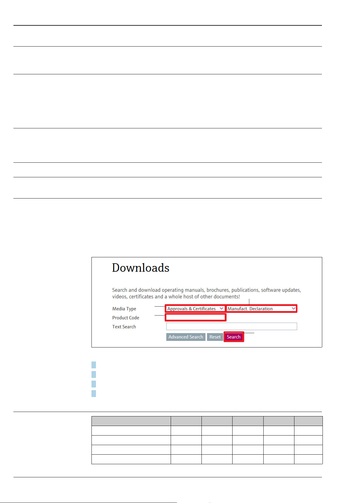
Deltapilot M FMB50/51/52/53
1
3
4
2
Certificate of Compliance
ASME BPE 2012 (FMB50
Ordering information:
Product Configurator, "Additional approval" ordering feature, option "LW"
only)
Functional safety SIL The Deltapilot M with 4 to 20 mA output signal has been developed to assessed and certified by
TÜV NORD CERT as per IEC 61508 Edition 2.0 and IEC 61511. These devices can be used to monitor
the process level and pressure up to SIL 2. For a detailed description of the safety functions with
Deltapilot M, settings and functional safety data, see the "Functional safety manual - Deltapilot M"
SD00347P.
Ordering information:
Product Configurator, "Additional approval:" ordering feature, option "LA".
Overfill protection WHG (FMB50, FMB51, FMB52): see document ZE00275P
Ordering information:
Product Configurator, "Additional approval" ordering feature, option "LC".
AD2000 The pressure retaining material 316L (1.4435/1.4404) corresponds to AD2000 - W2/W10.
Pressure Equipment Directive (PED)
The Deltapilot M device corresponds to Article 3 (3) of the EC directive 97/23/EC (Pressure Equipment
Directive) and has been designed and manufactured according to good engineering practice.
Manufacturer declaration •FDA conformity
• TSE-free, materials free from animal origin
• Regulation EC 2023/ 2006 (GMP)
• Regulation (EC) No. 1935/2004 on materials intended to come into contact with food
Downloading the manufacturer declaration
http://www.endress.com/en/download
1. Enter desired product code
2. Select "Approvals & Certificates"
3. Select "Manufact. Declaration"
4. Click on "Start Search"
The available downloads are displayed.
A0027319-EN
Marine approval
Designation FMB50 FMB51 FMB52 FMB53 Option
GL ―LE
ABS ―LF
LR ―LG
BV ―LH
1)
64 Endress+Hauser
Page 65

Deltapilot M FMB50/51/52/53
Other standards and guidelines
Drinking water approval
Designation FMB50 FMB51 FMB52 FMB53 Option
DNV ―LI
1) Product Configurator, "Additional options 1" and "Additional options 2" ordering feature
1)
DIN EN 60770 (IEC 60770):
Transmitters for use in industrial process control systems
Part 1: Methods for inspection and routine testing
DIN 16086:
Electrical pressure measuring instruments, pressure sensors, pressure transmitters, pressure
measuring instruments, concepts, specifications on data sheets
EN 61326 series:
EMC product family standard for electrical equipment for measurement, control and laboratory use.
EN 60529:
Degrees of protection by housing (IP code)
Designation Option
KTW LQ
NSF61 LR
ACS (under development) LS
1)
1) Product Configurator, "Additional options 1" and "Additional options 2" ordering feature
Classification of process sealing between electrical systems and (flammable or combustible) process fluids in accordance with ANSI/ ISA 12.27.01
Endress+Hauser instruments are designed according to ANSI/ISA 12.27.01 either as single seal or
dual seal devices with annunciation, allowing the user to waive the use and save the cost of installing
external secondary process seals in the conduit as required by the process sealing sections of ANSI/
NFPA 70 (NEC) and CSA 22.1 (CEC). These instruments comply with the North-American installation
practice and provide a very safe and cost-saving installation for pressurized applications with
hazardous fluids.
Further information can be found in the control drawings of the relevant devices.
Inspection certificate
Designation FMB50 FMB51 FMB52 FMB53 Option
3.1 Material certificate, wetted metallic parts, EN10204-3.1 inspection certificate JA
Conformity to NACE MR0175, wetted metallic parts JB
Conformity to NACE MR0103, wetted metallic parts JE
Conformity to AD2000, wetted metallic parts, excepting process membrane ― ― ―JF
Surface finish measurement ISO4287/Ra, wetted metallic parts, Inspection certificate ― ― ―KB
Helium leak test, internal procedure, inspection certificate KD
Pressure test, internal procedure, inspection certificate ―KE
3.1 Material certificate+Delta-Ferrit measurement, internal procedure, wetted metallic
parts, EN10204-3.1 inspection certificate
3.1 Material certificate+PMI test (XRF), internal procedure, wetted metallic parts,
EN10204-3.1 inspection certificate
― ― ―
2)
KF
KG
1)
1) Product Configurator, "Test, certificate" ordering feature
2) The selection of this feature for coated process isolating diaphragm / process connections refers to the metallic base material.
Endress+Hauser 65
Page 66

Deltapilot M FMB50/51/52/53
Calibration; unit
Calibration
Designation Option
Sensor range; % A
Sensor range; mbar/bar B
Sensor range; kPa/MPa C
Sensor range; mm/mH2O D
Sensor range; inH2O/ftH2O E
Sensor range; psi F
Customized pressure; see additional specification J
Customized level; see additional specification K
1) Product Configurator, "Calibration; unit" ordering feature
Designation Option
Factory calibration, 5-point F1
DKD/DAkkS calibration certificate 10-point
2)
F2
1) Product Configurator, "Calibration" ordering feature
2) Only for FMB50
1)
1)
Service
Designation Option
Oil and grease removed
Cleaned for oxygen service
2)
)
Cleaned from PWIS (PWIS = paint wetting impairment substances)
)
HA
HB
HC
Configured min alarm current IA
Configured HART Burst Mode PV IB
1) Product Configurator, "Service" ordering feature
2) Only device, not accessory or enclosed accessory
1)
66 Endress+Hauser
Page 67

Deltapilot M FMB50/51/52/53
Ordering information
Detailed ordering information is available as follows:
• In the Product Configurator on the Endress+Hauser website: www.endress.com → Click "Corporate"
→ Select your country → Click "Products" → Select the product using the filters and search field → Open
product page → The "Configure" button to the right of the product image opens the Product
Configurator.
• From your Endress+Hauser Sales Center: www.addresses.endress.com
Product Configurator - the tool for individual product configuration
• Up-to-the-minute configuration data
• Depending on the device: direct input of information specific to measuring point, such as measuring
range or operating language
• Automatic verification of exclusion criteria
• Automatic creation of the order code and its breakdown in PDF or Excel output format
• Ability to order directly in the Endress+Hauser Online Shop
Configuration data sheet Pressure
The following configuration data sheet has to be filled in and included with the order if the option J Customized pressure has been selected in feature 90 "Calibration; unit" in the ordering information.
Pressure Engineering Unit
mbar mmHO mmHg Pa
bar mH
psi inH
Calibration Range / Output
Low range value (LRV): _______________ [pressure engineering unit]
Upper range value (URV): _______________ [pressure engineering unit]
Display Information
1st Value Display
Main Value none (Default)
O
O kgf/cm2 kPa
ftH
O MPa
1)
2nd Value Display
Main Value [%] Pressure Current [mA] (HART only) Temperature
1)
1)
Depending on sensor and communication variant
Damping
Damping: __________ sec (Default 2 sec)
Endress+Hauser 67
Page 68

Deltapilot M FMB50/51/52/53
A
B
Level
The following configuration data sheet has to be filled in and included with the order if the option K Customized level has been selected in feature 90 "Calibration; unit" in the ordering information.
Pressure Engineering Unit Output Unit (Scaled unit)
mbar mmHO mmHg Pas Mass Length Volume Volume Percent
bar mH
psi inH
Empty pressure [a]:
Low pressure value (empty) ______________
O kPa
O kgf/cm2 MPa kg m l gal %
ftH
O t dm hl Igal
lb cm
mm m
ft in
ft
3
3
3
inch
Example
Empty calibration [a]:
Low level value (empty) ______________
[pressure
[Scaled Unit]
engineering unit]
Full pressure [b]:
High pressure value (full) ______________
Full calibration [b]:
High level value (full) ______________
[pressure
engineering unit]
Display Information
1st Value Display
1)
2nd Value Display
Main Value none (Default)
Main Value [%]
Pressure
Current [mA] (HART only)
Temperature
1)
Depending on sensor and communication variant
Damping
[Scaled Unit]
A0023621
A0 mbar / 0m
B 300 mbar (4.5psi) / 3 m (9.8 ft).
1)
Damping: __________ sec (Default 2 sec)
Smallest calibratable measuring span (preset at the factory) ä 14.
68 Endress+Hauser
Page 69

Deltapilot M FMB50/51/52/53
Accessories
Suspension clamp (FMB53 only)
Extension cable shortening kit (FMB53 only)
M12 connector ä 24 ff
Welding necks and Weld-in tool flanges
ä 30 ff
See Product Configurator, "Accessory enclosed" ordering feature, option "PW"
or can be ordered as a separate accessory (part no. 71125862). For details refer to SD00553P/00/A2.
Ordering information:
Product Configurator, "Enclosed accessories" ordering feature, option "RL, RM, RN".
See technical Information TI00426F/00.
Endress+Hauser 69
Page 70

Deltapilot M FMB50/51/52/53
47.5 (1.87)
39.5 (1.56)
29.5 (1.16)
26.5 (1.04)
Rd 52 x
Rd 65 x 1
ø44 (1.73)
ø78 (3.07)
ø56 (2.2)
ø51.6 (2.03)
1
6
/
"
Rd 52 x
ø44 (1.73)
1
6
/
"
ø68 (2.68)
ø92 (3.62)
ø61 (2.4)
ø51.6 (2.03)
47.5 (1.87)
39.5 (1.56)
28.5 (1.12)
25.5 (1)
Rd 78 x 1
Rd 52 x
ø44 (1.73)
1
6
/
"
ø84 (3.31)
ø105 (4.13)
ø65 (2.56)
ø51.6 (2.03)
39.5 (1.56)
31.5 (1.24)
6 (0.24)
Rd 52 x
ø44 (1.73)
1
6
/
"
39.5 (1.56)
ø64 (2.52)
ø51.6 (2.03)
Rd 52 x
ø44 (1.73)
1
6
/
"
39.5 (1.56)
ø84 (3.31)
ø68 (2.68)
Adapter Uni for FMB50 The following adapters can be used to create a connection between the customer's process connection
and the Deltapilot S FMB50 with a universal adapter:
A
C
A0020037
B
A0020038
D
A0020039
E
A0020041
Engineering unit mm (in)
Item Designation Material Weight
kg (lbs)
A DIN11851 DN40
B DIN11851 DN50 0.3 (0.66) 71114173 71114205 RB / R2
C DRD DN50 0.6 (1.32) 71114174 71114206 RC / R3
D Clamp 2" 0.2 (0.44) 71114176 71114207 RD / R4
E Varivent 0.5 (1.1) 71114177 71114208 RF / R6
1) Product Configurator, “Enclosed accessories” section
70 Endress+Hauser
AISI 316L (1.4435)
0.2 (0.44) 71114172 71114178 RA / R1
Order number Order number with
3.1 inspection certificate
Option
A0020040
1)
Page 71
Deltapilot M FMB50/51/52/53
Documentation
Technical Information • EMC test procedures: TI00241F/00/EN
• Deltabar M: TI00434P/00/EN
• Cerabar M: TI00436P/00/EN
Operating Instructions • 4...20 mA HART: BA00382P/00/EN
• PROFIBUS PA: BA00383P/00/EN
• FOUNDATION Fieldbus: BA00384P/00/EN
Brief Operating Instructions • 4...20 mA HART: KA01033P/00/EN
• PROFIBUS PA: KA01034P/00/EN
• FOUNDATION Fieldbus: KA01035P/00/EN
Functional safety manual
Deltapilot M (4 to 20 mA): SD00347P/00/EN
(SIL)
Safety Instructions
Directive Approval Category Type Electronics Documentation Option
Ex ia IIC II 1/2 G FMB50, FMB51, FMB52 – 4 to 20 mA HART – XA00474P/00 BA
Ex t IIC II 1/2 D FMB50, FMB51 – 4 to 20 mA HART – XA00475P/00 BB
– 4 to 20 mA HART
ATEX
1) Product Configurator, "Approval" ordering feature
Directive Approval EPL Type Electronics Documentation Option
IECEx
Ex nA II 3 G FMB50, FMB51, FMB52, FMB53
Ex ia IIC II 2 G FMB50, FMB51, FMB52, FMB53 – 4 to 20 mA HART – XA00474P/00 BE
Ex ic IIC II 3 G FMB50, FMB51, FMB52, FMB53 – 4 to 20 mA HART – XA00494P/00 BG
Ex ia IIC
Ex ia IIC
Ex ia IIC Ga/Gb FMB50, FMB51, FMB52 – 4 to 20 mA HART – XA00478P/00 IA
Ex ia IIC Gb FMB52, FMB53 – 4 to 20 mA HART – XA00478P/00 IC
Ex t IIIC Da/Db FMB50, FMB51 – 4 to 20 mA HART – XA00479P/00 ID
Ex ic IIC Gc FMB50, FMB51, FMB52, FMB53 – 4 to 20 mA HART – XA00493P/00 IE
Ex ia IIC
Ex ia IIIC
II 1/2 G
II 1/2 D
Ga/Gb
Da/Db
FMB50, FMB51 – 4 to 20 mA HART – XA00476P/00 B1
FMB50, FMB51 – 4 to 20 mA HART – XA00480P/00 I1
–PROFIBUS PA
– FOUNDATION Fieldbus
– XA00477P/00 BD
1)
1)
1) Product Configurator, "Approval" ordering feature
Directive Approval Type Electronics Documentation Option
NEPSI Ex ia IIC FMB50, FMB51, FMB52, FMB53
1) Product Configurator, "Approval" ordering feature
– 4 to 20 mA HART
–PROFIBUS PA
–FOUNDATION Fieldbus
– XA00535P/00 NA
1)
Endress+Hauser 71
Page 72
Deltapilot M FMB50/51/52/53
Directive Approval Electronics Documentation Option
TIIS Ex ia IIC T4 – 4 to 20 mA HART – TA
1) Product Configurator, "Approval" ordering feature
Directive Approval Type Electronics Documentation Option
– 4 to 20 mA HART
–PROFIBUS PA
– FOUNDATION Fieldbus
– XA01304P/00 MA
INMETRO
Ex ia IIC T6...T4 Ga/Gb
Ex ia IIC T6...T4 Gb
FMB50, FMB51, FMB52
1) Product Configurator, "Approval" ordering feature
Installation/Control Drawings
Directive Approval Type Electronics Documentation Option
FM
CSA
FM IS Cl.I,II,III Div.1 Gr.A-G, AEx ia,
FM NI Cl.I Div.2 Gr.A-D,
FM IS: Zone 0, 1, 2, 20, 21, 22/
FMB50
FM NI: Zone 2
FM IS Cl.I,II,III Div.1 Gr.A-G, AEx ia,
FMB51 – 4 to 20 mA HART
Zone 0,1, 2, 20, 21, 22
FM DIP Cl.II,III Div.1 Gr.E-G,
FMB50, FMB51 – 4 to 20 mA HART
Zone 21, 22
FM NI Cl.I Div.2 Gr.A-D,
FMB50, FMB51 – 4 to 20 mA HART
Zone 2
FM IS Cl.I Div.1 Gr.A-D, AEx ia,
FMB52, FMB53 – 4 to 20 mA HART
Zone 0, 1, 2
C/US IS Cl.I,II,III Div.1 Gr.A-G,
C/US IS Cl.I Div.2 Gr.A-D, Ex ia,
FMB50, FMB53
Zone 0,1, 2
C/US IS Cl.I,II,III Div.1 Gr.A-G,
C/US IS Cl.I Div.2 Gr.A-D,
Ex ia C: Zone 0, 1, 2/
FMB51, FMB52
US: Zone 0, 1, 2, 20, 21, 22
CSA C/US Cl.II, III Div.1 Gr.E-G FMB50 – 4 to 20 mA HART –
CSA C/US Cl.II, III Div.1 Gr.E-G
FMB51 – 4 to 20 mA HART
US: Zone 21, 22
– 4 to 20 mA HART
– PROFIBUS PA, FOUNDATION Fieldbus
– ZD00236P/00
– XA00566P/00
– PROFIBUS PA, FOUNDATION Fieldbus–– XA00566P/00
–PROFIBUS PA
–FC
– FOUNDATION Fieldbus
–PROFIBUS PA
–FD
– FOUNDATION Fieldbus
– ZD00236P/00
– PROFIBUS PA. FOUNDATION Fieldbus
– 4 to 20 mA HART
– PROFIBUS PA, FOUNDATION Fieldbus
– XA00566P/00
– ZD00239P/00
– XA00560P/00
– 4 to 20 mA HART
– PROFIBUS PA, FOUNDATION Fieldbus–– XA00560P/00
–
FA
FE
CA
CC
1)
1)
1)
1) Product Configurator, "Approval" ordering feature
Combination certificate
Directive Approval Electronics Documentation Option
– ZD00236P/00
– ZD00239P/00
– XA00474P/00
KEMA/
FM / CSA
ATEX II Ex ia + FM/CSA IS
ATEX II 1/2G Ex ia IIC T6 +
FM/CSA IS CL.I Div.1 Gr.A-D,
FM/CSA: Zone 0,1,2
– 4 to 20 mA HART
PROFIBUS PA,
FOUNDATION Fieldbus
1)
8C
1) Product Configurator, "Approval" ordering feature
Overfill protection WHG (FMB50, FMB51, FMB52): ZE00275P/00/DE
72 Endress+Hauser
Page 73

Deltapilot M FMB50/51/52/53
Registered trademarks
HART® Registered trademark of the FieldComm Group, Austin, USA
PROFIBUS® Registered trademark of the PROFIBUS User Organization, Karlsruhe, Germany
FOUNDATION™ Fieldbus Registered trademark of the FieldComm Group, Austin, USA
Endress+Hauser 73
Page 74

Deltapilot M FMB50/51/52/53
74 Endress+Hauser
Page 75

Deltapilot M FMB50/51/52/53
Endress+Hauser 75
Page 76

www.addresses.endress.com
71316865
 Loading...