

Endress+Hauser Flowphant T DTT35 Technical Information
TI00125R/09/en
71009492
Technical information
Flow switch
Flowphant
®
T DTT31, DTT35
Flow switch for safe monitoring of mass flow and temperature in
industrial processes
Application
Flow switch for monitoring and displaying relative mass flow
rates of liquid media in the range from
0.03 to 3 m/s (0.1 to 9.84 ft/s):
Flowphant
®
T DTT31
− with thread connections or coupling
Flowphant
®
T DTT35
− with process connections for hygienic applications
Application examples:
• Monitoring cooling water circulation systems of pumps,
turbines, compressors and heat exchangers
• Monitoring pump functionality
• Leak monitoring in process lines
• Monitoring lubrication systems
• Filter monitoring in the beverage industry
Benefits at a glance
This compact flow switch impresses with the latest in
technology being used:
• Practically no pressure loss
• Configuration software ReadWin
®
2000 or FieldCare for
quick configuration and reliable storage of device settings
• Optional: 4 to 20 mA analog output to read out the flow rate
as percentage value
• Optional: second switch output or 4 to 20 mA analog output
for temperature monitoring
• Function check and process information onsite thanks to
digital display at device
• Top housing section which can be rotated 310° and rotatable
display make it possible to read the measured values in all
orientations
• DTT35: 3-A marked
DTT31, DTT35
2 Endress+Hauser
Function and system design
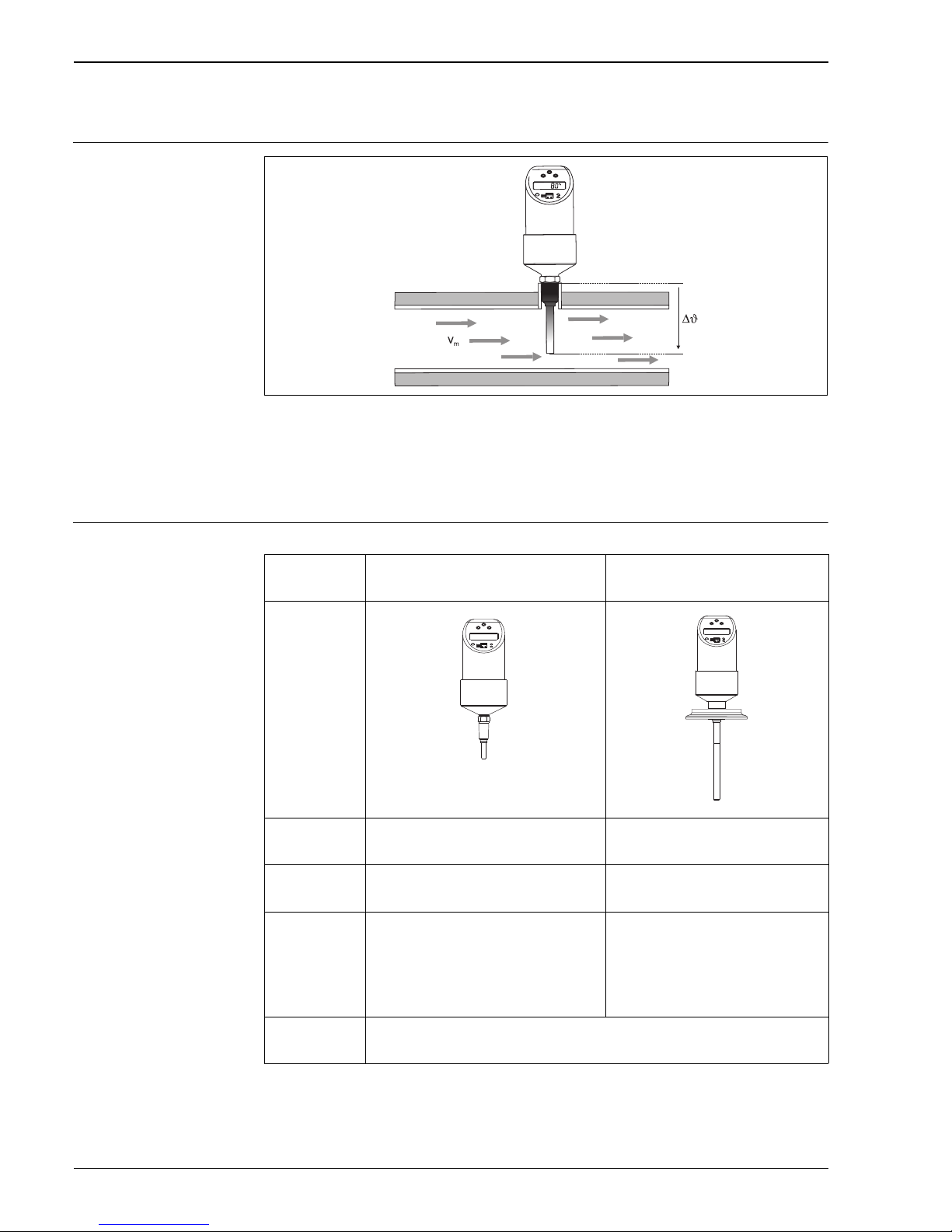
Measuring principle
T09-DTT31xxx-15-xx-xx-xx-000
The device measures the mass flow of a liquid medium with the calorimetric measurement method. The
calorimetric measuring principle is based on cooling a heated temperature sensor. Heat is removed from the
sensor by forced convection due to medium flowing by. The extent of this heat transfer depends on the medium
velocity and the difference in temperature between the sensor and medium (King's law). The higher the
velocity or the mass flow of the medium, the greater the temperature sensor cooling.
Measuring system Overview
Flowphant
®
product family
DTT31 DTT35
a0005276
T09-TTR35xxx-14-xx-xx-xx-000
Measurement
probe
RTD RTD
Field of
application
Monitoring of the mass flow of water, waterlike substances and low-viscosity oils.
Monitoring of the mass flow of liquid media
in hygienic processes.
Process
connection
• Compression fitting
•Thread:
− G½" and G¼"
− ANSI NPT ¼" and NPT ½"
•Hygiene:
− Conical metal-metal G½"
− Clamp 1" - 1½", 2"
− Varivent F, N
− DIN 11851
− APV-Inline
Measuring range Mass flow as a relative value between 0 and 100%.
Process measuring limit, liquids: 0.03 to 3 m/s (0.1 to 9.84 ft/s)
DTT31, DTT35
Endress+Hauser 3
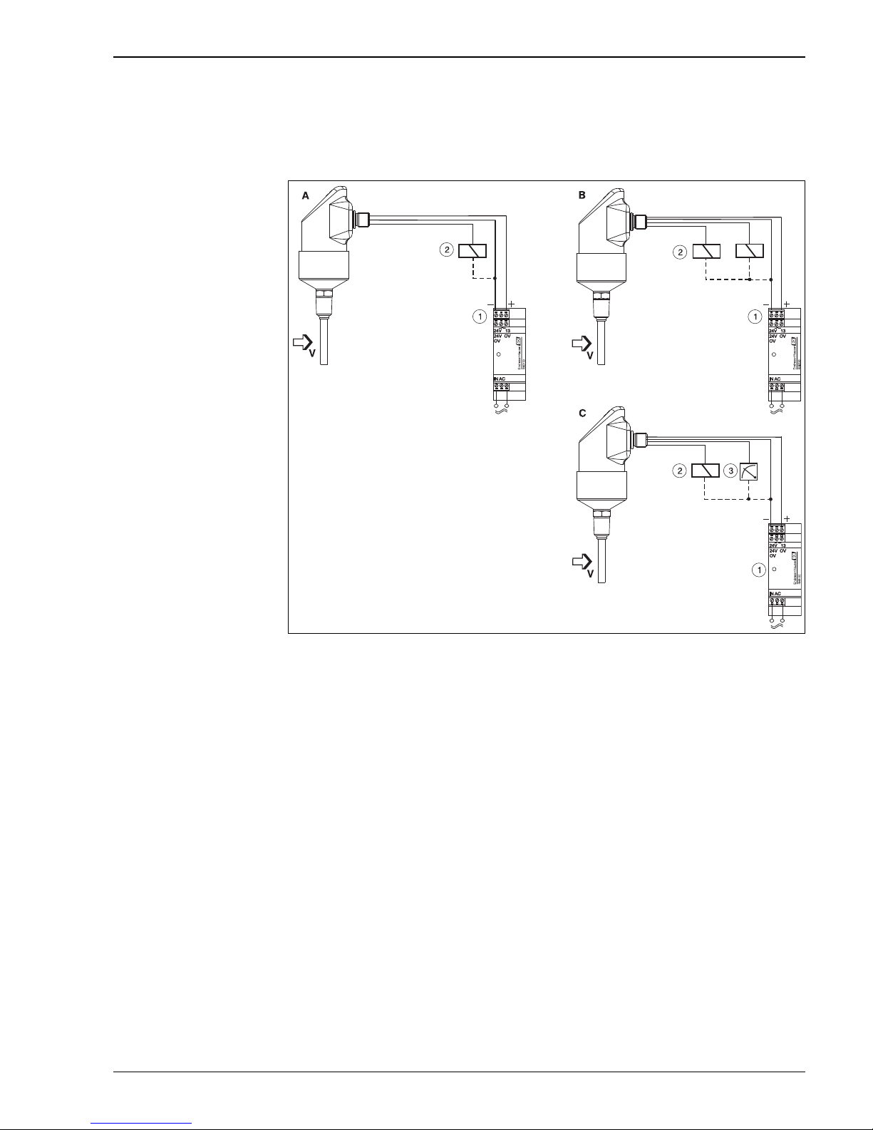
DC voltage version
PNP switch output of electronics.
Power supply e.g. with a power supply unit.
Preferably in conjunction with programmable logic controllers (PLC) or for controlling a relay.
a0005373
A: 1x PNP switch output
B: 2x PNP switch output
C: PNP switch output with additional analog output 4 to 20 mA
m Transmitter power supply unit, e.g. RNB130
n Load (e.g. programmable logic controller, process control system, relay)
o Display e.g. RIA452 or recorder e.g. Ecograph T or Minilog B (at 4 to 20 mA analog output)
m Power supply "Easy Analog RNB130":
Primary switched-mode power supply for sensors. Space saving DIN rail mounting as per IEC 60715.
Wide-range nominal voltage input: 100 to 240 V AC; Output: 24 V DC, max. 30 V in the event of a fault;
Nominal output current: 1.5 A. Connection to monophased a.c. networks or to two phase conductors of threephase supply networks.
n Process display RIA452:
If you would like to read off the instantaneous value of the temperature not only locally, but also e.g. directly
from a control room or in the PC network, then one suitable device is the process display RIA452:
Digital process display unit in 96 x 96 mm (3.78 x 3.78 in) panel mounted housing for monitoring and
displaying analog measured values with pump control and batch functions. Multicoloured 7-digit 14-segment
LC display with large bargraph. Configuration and visualisation via RS232 interface and ReadWin
®
2000 PC
operating software.
o Multi Channel Recorder Ecograph T, Data logger Minilog B:
If you would like to read off the instantaneous value of the temperature not only locally, but also record, analyze
and display it e.g. directly from a control room or in the PC network, then the following devices are suitable:

DTT31, DTT35
4 Endress+Hauser
• Multi Channel Recorder Ecograph T
144 x 144 mm (5.67 x 5.67 in) panel mounted housing for electronic acquisition, display, recording,
analysis, remote transmission and archiving of analog and digitalinput signals. Data recording system with
CompactFlash card and multi-coloured LCD display (120 mm / 4.7 in screen size). Configuration and
visualisation via interface (USB, Ethernet, RS232/485) and ReadWin
®
2000 PC operating software.
• Data logger Minilog B
Battery powered measured value collector with 2 input channels for storing analog and digital values.
Internal memory 128 kB for max. 84000 measured values. Configuration and visualisation via RS232
interface and ReadWin
®
2000 PC operating software. Optionally with telealarm function.
Input
Measured variable • Flow velocity of liquid media (calorimetric measuring principle)
• Temperature (RTD), optional for two switch outputs or additional analog output
Measuring range • Flow: 0.03 m/s to 3 m/s (0.1 to 9.84 ft/s), as relative value between 0 and 100%; maximum display
resolution: 1%
• Temperature: -20 °C to +85 °C (-4 to +185 °F); display resolution: 1 °C (1 °F)
Output
Output signal DC voltage version: (short-circuit proof version)
• 1x PNP switch output (flow) or
• 2x PNP switch outputs (flow or temperature, adjustable) or
• 1x PNP switch output and 1x 4 to20 mA output, active (flow or temperature, adjustable)
!
Note!
The analog output reads out the measured flow rate as relative value in percentage of the adjusted measuring
range.
Signal on alarm Signal on alarm as per NAMUR NE43
• Underranging: Linear drop to 3.8 mA
• Overranging: Linear rise to 20.5 mA
• Sensor break; sensor short-circuit:
≤ 3.6 mA or ≥ 21.0 mA (at settings ≥ 21.0 mA, 21.7 mA output is guaranteed)
• Switch outputs: at safety condition (switch open)
Load Max. (V
power supply
- 6.5 V) / 0.022 A (current output)
Range of adjustment • Switch output
Switch point (SP) and switchback point (RSP) in increments of 1% with min. hysteresis of 5%
• Damping: freely adjustable: 0 = off (no damping) or 10 to 40 s in increments of 1 second
• Unit: %, optional °C, °F (with two outputs and temperature monitoring)
Switching capacity DC voltage version:
• Switch status ON: I
a
≤ 250 mA, switch status OFF: Ia ≤ 1 mA
• Switching cycles: > 10,000,000
• Voltage drop PNP: ≤ 2 V
• Overload protection
Automatic testing of switching current; output is switched off in case of overcurrent, the switching current
is tested again every 0.5 s; max. capacitance load: 14 μF for max. supply voltage (without resistive load)
Periodic disconnection from a protective circuit in event of overcurrent (f = 2 Hz) and indication of
’Warning’

DTT31, DTT35
Endress+Hauser 5
Inductive load To prevent electrical interference, only operate an inductive load (relays, contactors, solenoid valves) when
directly connected to a protective circuit (free-wheeling diode or capacitor).
Power supply
Electrical connection Plug connection
!
Note!
DTT35: Electrical cables must comply with 3-A standard, must be smooth, corrosion resistant and cleanable.
T09-TTR31xxx-04-00-xx-xx-000
A: M12x1 connector
B: Valve connector M16x1.5 or NPT ½"
Device connection
• DC voltage version with M12x1 connector
a0006818
Item No. Output setting Order code (see Ordering information section)
A1 1x PNP switch output DTT3x-A1A*******
A2 2x PNP switch output R1 and m (R2) DTT3x-A1B*******
A2’ 2x PNP switch output R1 and m (diagnosis/NC
contact with "DESINA" setting)
DTT3x-A1B*******
A3 1x PNP switch output and 1x analog output
(4 to 20 mA)
DTT3x-A1C*******
DTT31, DTT35
6 Endress+Hauser
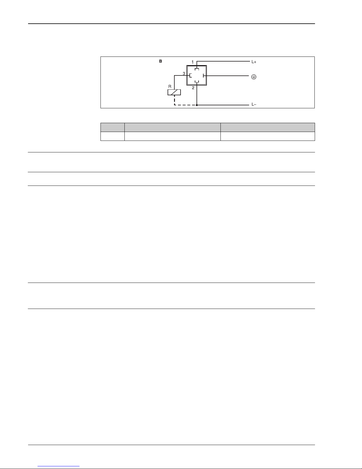
• DC voltage version with valve connector M16x1.5 or NPT ½"
P01-PTx3xxxx-04-xx-xx-xx-003
Supply voltage DC voltage version
18 up to 30 V DC (reverse polarity protection)
Current consumption < 100 mA (without load) at 24 V DC, max. 150 mA (without load); with reverse polarity protection
Power supply failure • Behaviour in case of overvoltage (> 30 V)
The device works continuously up to 34 V DC without any damage.
No damage is caused to the device in case of a short-term overvoltage up to 1 kV (as per EN 61000-4-5).
The specific properties are no longer guaranteed if the supply voltage is exceeded.
• Behaviour in case of undervoltage
If the supply voltage drops below the minimum value, the device switches off (status as if not supplied with
power = switch open).
Performance characteristics
The percentage information in the "Performance characteristics" section refers to the full scale value or the set
maximum value (100% value) of the monitoring range.
Reference operating
conditions
As per DIN IEC 60770 or DIN IEC 61003
T = 25 °C ± 5 °C (77 °F ± 9 °F), relative humidity 45 to 75 %, ambient air pressure 860 to 1060 kPa
(124 to 153 PSI), water test medium. Supply voltage U = 24 V DC.
Maximum measured error Flow
The device records fluid velocity relatively in relation to a set monitoring range of the flow (0 to 100 % as
display value). An absolute measurement of the fluid velocity or the mass flow is not possible. The sensitivity
of the calorimetric flow sensor changes with the fluid velocity. It increases with decreasing fluid velocity (for
example, with water, the greatest sensor sensitivity is recorded in the range from 0.03 to 0.5 m/s).
Item No. Output setting Order code (see Ordering information section)
B 1x PNP switch output DTT3x-A2A*******; DTT3x-A3A*******
 Loading...