

Page 1
Products Solutions Services
BA00235R/09/EN/16.14
71252244
SW Version
01.00
Operating Instructions
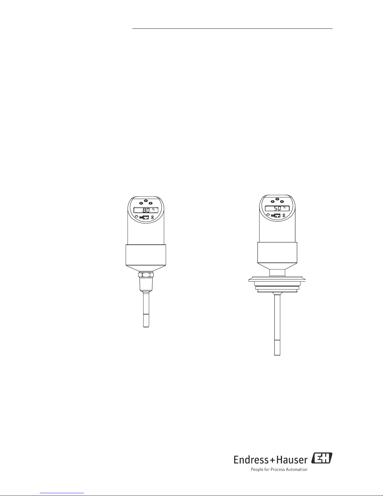
Flowphant T
DTT31, DTT35
Flow Switch
AUTHORIZED DISTRIBUTOR:
InstrumentsAndControl.com
Houston, Texas USA
sales@InstrumentsAndControl.com
832-615-3588
Page 2

Brief overview
For quick and easy commissioning:
Safety instructions → Page 4
Æ
Installation → Page 7
Æ
Wiring → Page 13
Æ
Operation → Page 14
Display and operating elements
Onsite operation
Operation with PC and configuration software
Æ
Troubleshooting → Page 32
Page 3

Endress+Hauser
DTT31, DTT35
Table of contents
1 Safety instructions . . . . . . . . . . . 4
1.1 Designated use . . . . . . . . . . . . . . . . . . . . . . 4
1.2 Installation, commissioning and
operation . . . . . . . . . . . . . . . . . . . . . . . . . . 4
1.3 Operational safety . . . . . . . . . . . . . . . . . . . 4
1.4 Return . . . . . . . . . . . . . . . . . . . . . . . . . . . . . 4
1.5 Notes on safety conventions and icons . . 5
2 Device identification . . . . . . . . . 6
2.1 Nameplate . . . . . . . . . . . . . . . . . . . . . . . . . 6
2.2 Certificates and approvals . . . . . . . . . . . . 6
3 Installation . . . . . . . . . . . . . . . . . 7
3.1 Incoming acceptance, storage . . . . . . . . . 7
3.2 Dimensions . . . . . . . . . . . . . . . . . . . . . . . . . 7
3.3 Process connection . . . . . . . . . . . . . . . . . . 8
3.4 Installation instructions . . . . . . . . . . . . . 10
4 Wiring . . . . . . . . . . . . . . . . . . . . 12
4.1 DC voltage version with M12x1
connector . . . . . . . . . . . . . . . . . . . . . . . . . 12
4.2 DC voltage version with valve connector 13
5 Operation. . . . . . . . . . . . . . . . . . 13
5.1 Onsite operation . . . . . . . . . . . . . . . . . . . 13
5.2 Operation with PC and configuration
software . . . . . . . . . . . . . . . . . . . . . . . . . . 25
6 Maintenance. . . . . . . . . . . . . . . 26
7 Accessories . . . . . . . . . . . . . . . . 27
7.1 Welding bosses and coupling . . . . . . . . 27
7.2 Electrical connection . . . . . . . . . . . . . . . . 28
7.3 Configuration kit . . . . . . . . . . . . . . . . . . . 29
7.4 Configuration software . . . . . . . . . . . . . . 30
8 Troubleshooting. . . . . . . . . . . . 31
8.1 Error messages and warning messages 31
8.2 Repair . . . . . . . . . . . . . . . . . . . . . . . . . . . . 32
8.3 Disposal . . . . . . . . . . . . . . . . . . . . . . . . . . . 32
8.4 Change status (release) . . . . . . . . . . . . . 33
8.5 Software history . . . . . . . . . . . . . . . . . . . . 33
9 Technical data. . . . . . . . . . . . . . 34
9.1 Power supply . . . . . . . . . . . . . . . . . . . . . . . 34
9.2 Output . . . . . . . . . . . . . . . . . . . . . . . . . . . . 34
9.3 Operating conditions . . . . . . . . . .. . . . . . . . 35
Page 4

Safety instructions DTT31, DTT35
4 Endress+Hauser
1 Safety instructions
1.1 Designated use
The Flowphant T is a flow switch for monitoring mass flow rates in industrial processes. The
device is designed to meet state-of-the-art safety requirements and conforms to applicable
standards and EC regulations. It can, however, be a source of danger if used incorrectly or for
anything other than the designated use.
1.2 Installation, commissioning and operation
Installation, electrical connection, commissioning, operation and maintenance of the measuring
system must be carried out by trained, qualified specialists authorized to perform such work by
the facility's owner-operator. The specialist must have read and understood these Operating
Instructions and must follow the instructions they contain. The device may only be modified and
repair work carried out if this is explicitly permitted in the Operating Instructions. Damaged
devices which could be a source of danger may not be commissioned and must be labeled and
identified as defective.
1.3 Operational safety
• Functional safety
The Flowphant T flow switch has been developed in accordance with the IEC 61508 and
IEC 61511-1 (FDIS) standards. The device version with a PNP switch output and additional
analog output is equipped with features for detecting and preventing errors within the
electronics and software.
•Ex-area
The Flowphant T is not approved for use in Ex-areas.
1.4 Return
The following procedures must be carried out before a device is returned to Endress+Hauser:
• Always enclose a fully completed “Declaration of Contamination” form with the device. Only
then can Endress+Hauser transport and examine a returned device. A copy of the
“Declaration of Contamination” can be found on the second last page of these Operating
Instructions.
• Remove all fluid residues. This is particularly important if the fluid is hazardous to health, e.g.
flammable, toxic, caustic, carcinogenic, etc.
WARNING
!
Do not return a device if you are not absolutely certain that all traces of hazardous
substances have been removed, e.g. substances which have penetrated crevices or diffused
through plastic.
Page 5
DTT31, DTT35 Safety instructions
Endress+Hauser 5
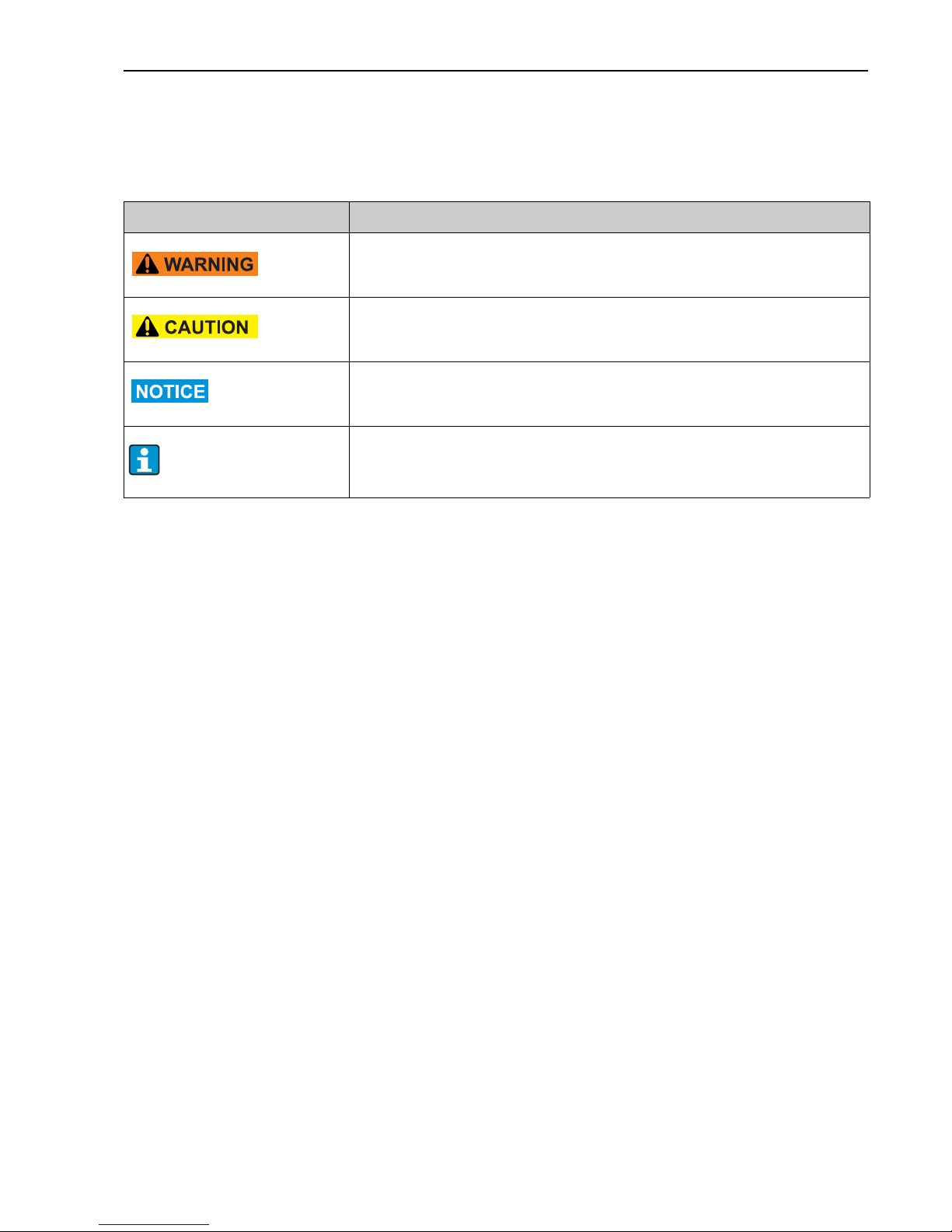
1.5 Notes on safety conventions and icons
Always refer to the safety instructions in these Operating Instructions labeled with the following
symbols:
Symbol Meaning
A0011190-EN
WARNING!
This symbol alerts you to a dangerous situation. Failure to avoid this situation can
result in serious or fatal injury.
A0011191-EN
CAUTION!
This symbol alerts you to a dangerous situation. Failure to avoid this situation can
result in minor or medium injury.
A0011192-EN
NOTICE
This symbol contains information on procedures and other facts which do not
result in personal injury.
A0011193
Indicates additional information, Tip
Page 6
Device identification DTT31, DTT35
6 Endress+Hauser
2 Device identification
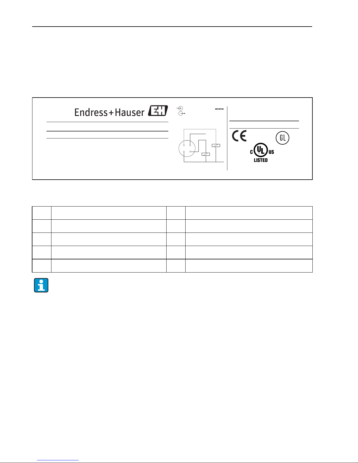
2.1 Nameplate
To identify your device, compare the complete order code and the version information on the
delivery papers with the data on the nameplate.
A0006981
Fig. 1: Nameplate for device identification (as example)
2.2 Certificates and approvals
CE mark, declaration of conformity
On leaving the factory, the device was in perfect condition from the point of view of safety. It
complies with the standards EN 61010 -1 "Protection Measures for Electrical Equipment for
Measurement, Control, Regulation and Laboratory Procedures" and with the EMC requirements
of IEC/EN 61326. The device meets the legal requirements of the EU Directives. The
manufacturer confirms a positive completion of all tests by fitting the unit with a CE mark.
Hygiene standard
The DTT35 flow switch meets the requirements of Sanitary Standard no. 74-06.
Endress+Hauser confirms this by applying the 3–A symbol (not valid for process connection
conical metal-metal).
16YV
MEASURING EQUIPMENT
m
n
o
p
q
r
s
t
u
v
Flowphant T
Made in Germany D-87484 Nesselwang
Order Code: DTT3x-xxxxxxxx
Ser.No.: xxxxxxxxxxxxxx
TAG No.: Xxxxxxxxxxxxxxxxxx
Xxxxxxxxxxxxxxxxxx
Rel.: X.XX.XX
Flow (0.03 … 3m/s; -20 °C...+85 °C)
-40°C < Ta < 85°C
Output < 250 mA
Current consump.100mA
18 - 30V DC
PNP
1
4
3
2
L+
L-
12
IP6X
m Order code r Connection diagram
n Serial number s Measuring range
o TAG number t Ambient temperature range
p Release number (change status) u Degree of protection
q Connection values v Approvals
The release number indicates the change status of the device. A change in the last two
figures does not have any affect on the compatibility, → Chap. 8.4.
Page 7
DTT31, DTT35 Installation
Endress+Hauser 7
UL listed for Canada and USA
The device was examined by Underwriters Laboratories Inc. (UL) in accordance with the
standards UL 61010B-1 and CSA C22.2 No. 1010.1-92 and listed under the number E225237
UL.
3 Installation
3.1 Incoming acceptance, storage
• Incoming acceptance:
Check the packaging and the device for damage. Check that the goods delivered are complete
and nothing is missing.
•Storage:
Storage temperature -40 °C to +85 °C (-40 °F to 185 °F).
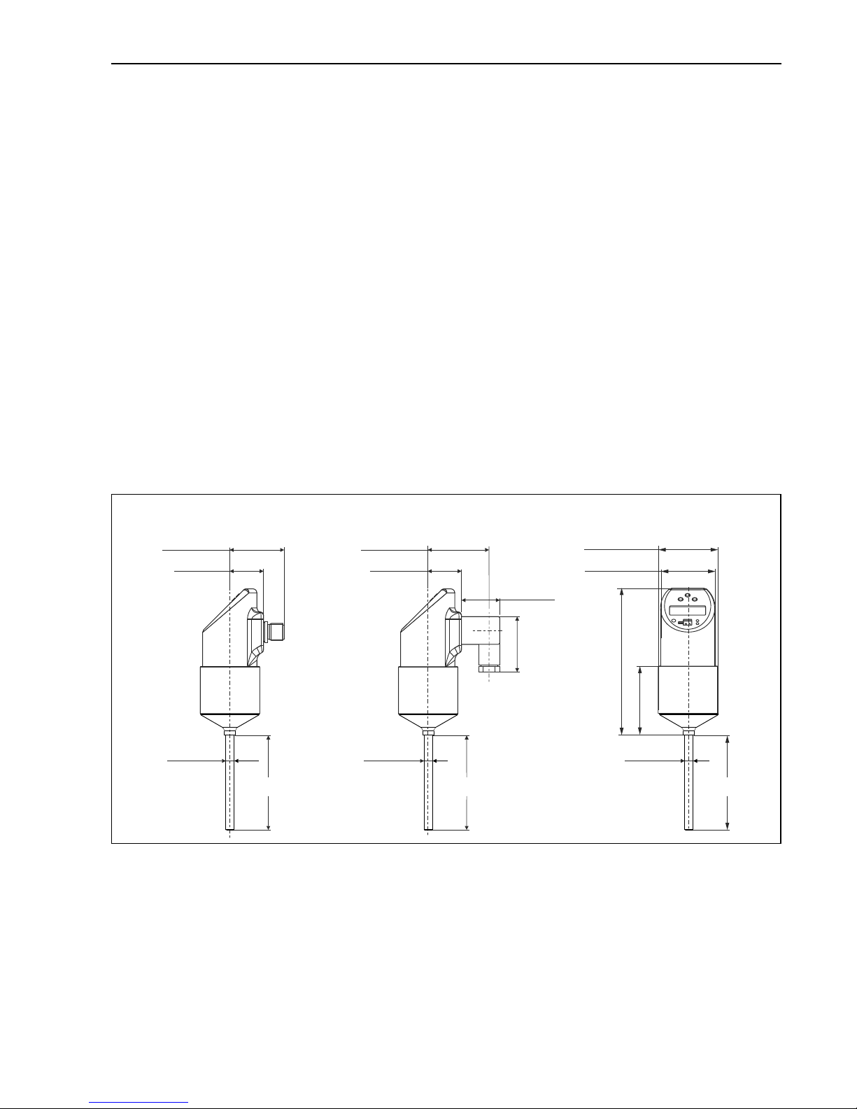
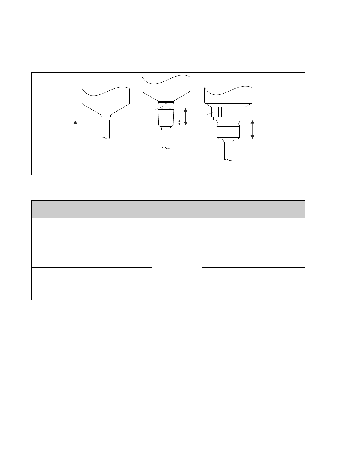
3.2 Dimensions
A0005279
Fig. 2: Dimensions in mm (in)
Version L with 30 and 100 mm (1.18 and 3.94 in) for DTT31
Version L with 30, 50 and 100 mm (1.18, 1.97 and 3.94 in) for DTT35
M12x1 connector as per IEC 60947-5-2
M16x1.5 or NPT ½" valve connector as per DIN 43650A/ISO 4400
42.3 (1.66)
97.1 (3.82)
42.1 (1.66)
38.7 (1.52)
38.7 (1.52)
36 (1.42)
24 (0.95)
24 (0.95)
52 (2.05)
38.5 (1.52)
M16x1.5 / NPT ½”
M12x1
LL L
6 (0.24)
6 (0.24)
6 (0.24)
Page 8
Installation DTT31, DTT35
8 Endress+Hauser
3.3 Process connection
3.3.1 DTT31 design, dimensions of the process connections
A0007101
Fig. 3: Process connection versions of DTT31
m
AB
C
n
L
L1
L2
L1 = L2
Item
no.
Version Insertion length L Thread length L
1
Thread length L
2
A Without process connection. For suitable
welding boss and coupling see chapter
’accessories’.
30 or 100 mm
(1.18 or 3.94 in)
--
B Thread process connection:
• ANSI NPT ¼" (m = AF15)
• ANSI NPT ½" (m = AF22)
• 14.3 mm (0.56 in)
• 19 mm (0.75 in)
• 5.8 mm (0.23 in)
• 8.1 mm (0.32 in)
C Thread process connection cylindrical as
per ISO 228:
•G¼" (n = AF19)
•G½" (n = AF27)
• 12 mm (0.47 in)
• 14 mm (0.55 in)
-
Page 9
DTT31, DTT35 Installation
Endress+Hauser 9
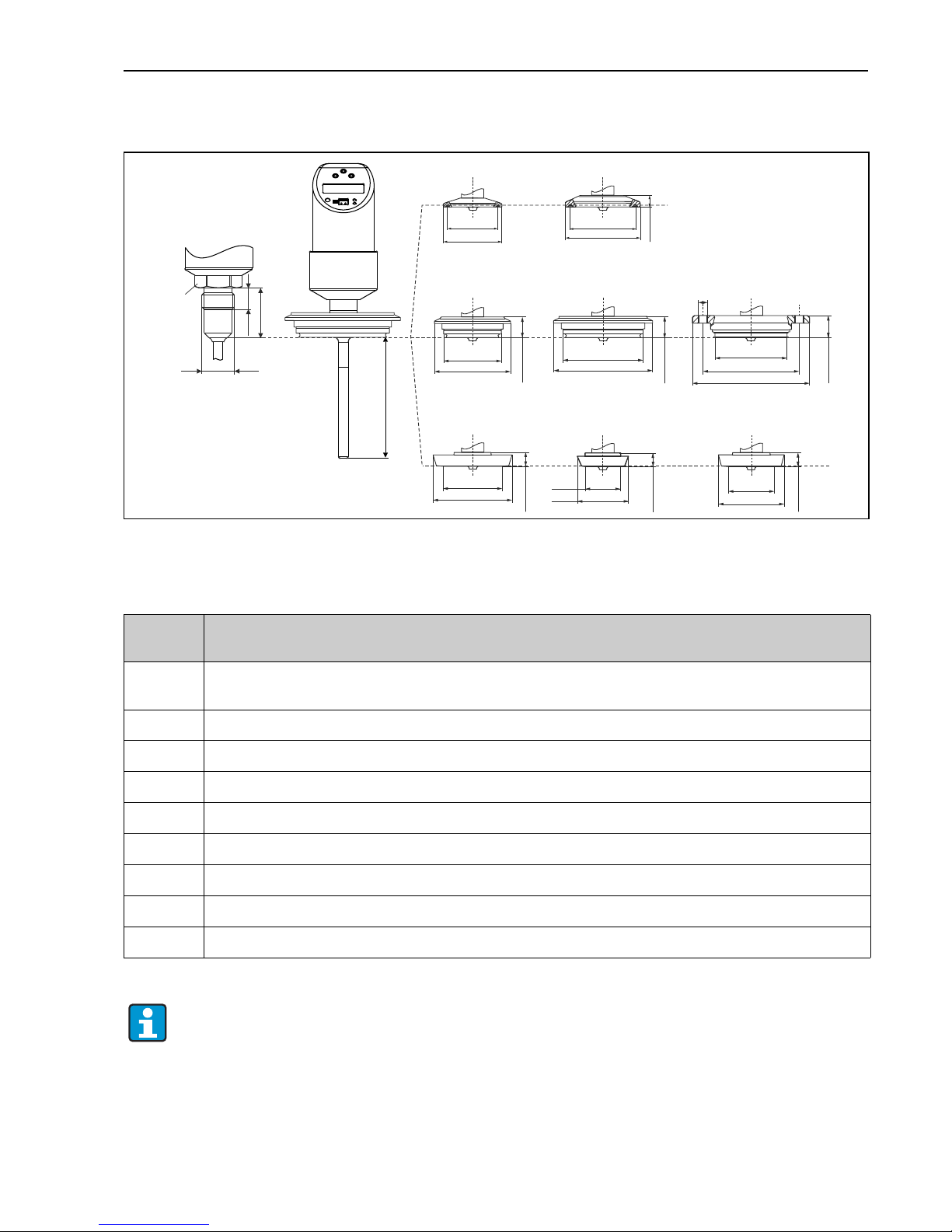
3.3.2 DTT35 design, dimensions of the process connections
A0011776
Fig. 4: Hygienic process connections. All dimensions in mm (in)
L = Insertion length L
DB
DL
56.5 (2.22)
64 (2.52)
LL
18 (0.71)
HL
B
19 (0.75)
PL
13 (0.51)
PH
13 (0.51)
(APV-Inline)
(CLAMP 1”) (CLAMP 2”)
(Varivent N)
LB
18 (0.71)
(Varivent F)
(DIN 11851)
(DIN 11851)
L
13 (0.51)
PG
(DIN 11851)
10 (0.39)
MB
L1
SW/
AF 22
37 (1.46)
G½”
43.5 (1.71)
50.5 (1.99)
84 (3.31)
68 (2.68)
61.5 (2.42)
82 (3.23)
100 (3.94)
66 (2.6)
50 (1.97)
51 (2.01)
68 (2.68)
27 (1.06)
44 (1.73)
39 (1.54)
56 (2.21)
Item no. Process connection versions DTT35
Insertion length L = 30, 50 or 100 mm (1.18, 1.97 or 3.94 in)
MB Conical metal-metal for hygienic processes, G½" thread, thread length L1 = 14 mm (0.55 in).
Suitable welding boss available as accessory.
DB Clamp 1"...1½" (ISO 2852) or DN 25...DN 40 (DIN 32676)
DL Clamp 2" (ISO 2852) or DN 50 (DIN 32676)
LB Varivent F DN25-32, PN 40
LL Varivent N DN40-162, PN 40
HL APV-Inline, DN50, PN40, 316L, B = bores 6 x Ø8.6 (0.34 in) + 2 x thread M8
PL DIN 11851, DN50, PN40 (including coupling nut)
PG DIN 11851, DN25, PN40 (including coupling nut)
PH DIN 11851, DN40, PN40 (including coupling nut)
The maximum process pressure for the conical metal-metal process connection
(→ Fig. 4, item MB) is 16 bar!
Page 10
Installation DTT31, DTT35
10 Endress+Hauser
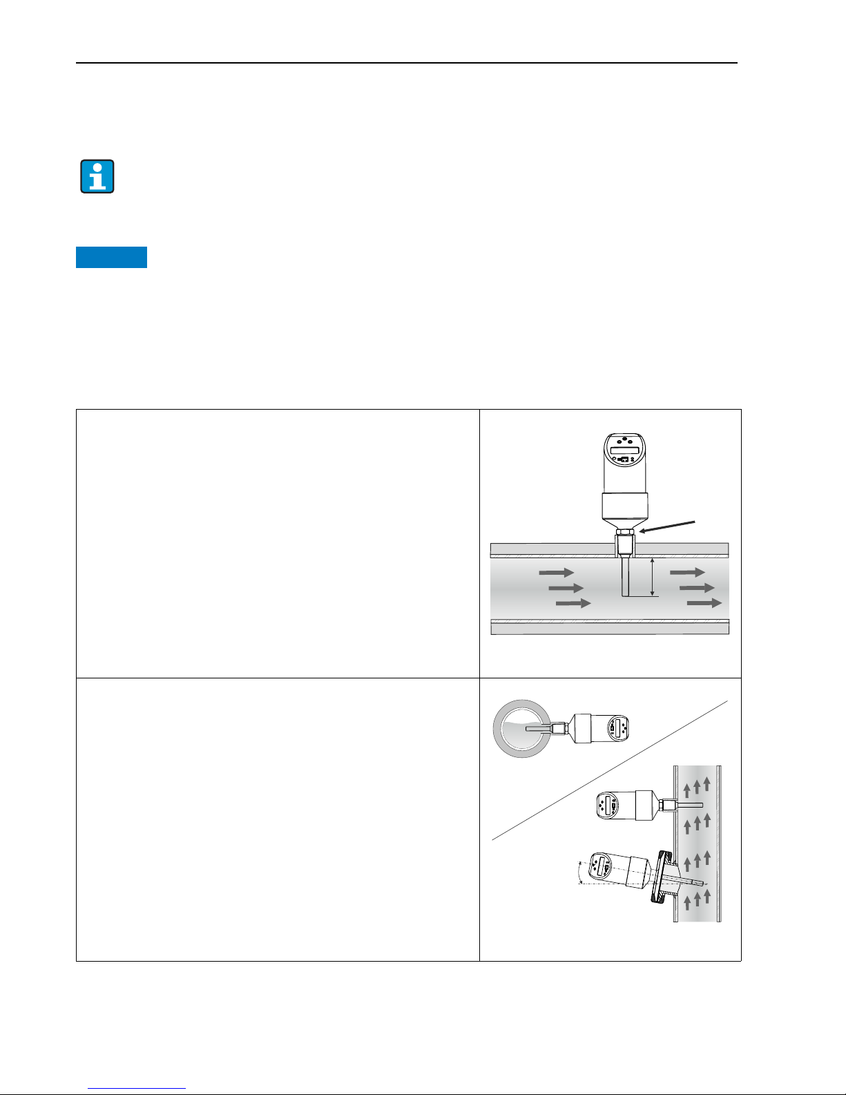
3.4 Installation instructions
3.4.1 Installation conditions
NOTICE
Do not turn the device into the process connection thread at the housing. Always install the
device at the spanner flats (Fig. 5, item 1). Use a suitable open-ended wrench for this task (see
Table → Chap. 3.3.1).
• The onsite display can be rotated electronically 180°, → Chap. 5.1 "Onsite operation".
• The upper housing section can be rotated mechanically up to 310°.
The sensor requires a fully developed flow profile for correct monitoring.
For this reason, steadying sections (5x DN) must be provided in the pipe after a pump,
pipe bend, internal fittings and cross-sectional changes.
• The sensor tip should be completely surrounded by medium.
• Position the sensor tip in the area of maximum fluid velocity (pipe
center).
• Minimum sensor immersion length: L
i
≥10 mm.
A0006976
Fig. 5: Installation conditions
Orientation
• For horizontal pipes: lateral installation.
Installation from above (see Fig. 5) only if the pipe is completely
filled with medium during operation.
• For vertical pipes: installation in the ascending pipeline.
• Installation of DTT35 by min. 3° inclination, because of self draining.
A0006977
Fig. 6: Correct orientation
80
%
L
i
v
m
1
80
%
80
%
80
%
3°=
Page 11
DTT31, DTT35 Installation
Endress+Hauser 11
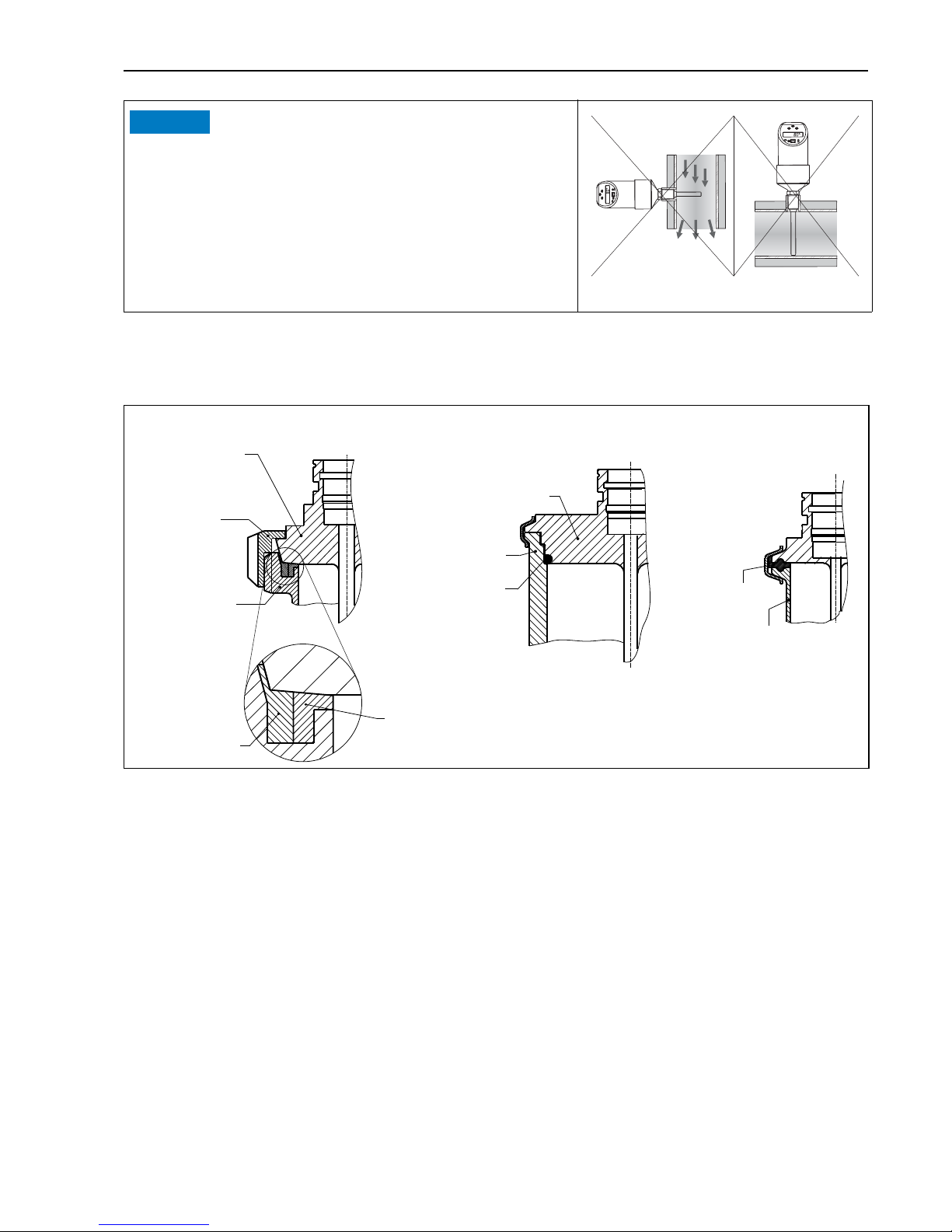
3.4.2 Mounting instructions for installation in hygienic processes
A0011673-EN
Fig. 8: Installation in hygienic processes
A Milk pipe connection as per DIN 11851 (connection PL, PG, PH), only in linkage with EHEDG certified and self
centering ring
B Varivent and APV-Inline (connection LB, LL, HL)
C Clamp as per ISO 2852 (connection DB, DL)
NOTICE
Do not install in down pipes open towards the end.
The sensor tip should never touch the pipe wall.
A0006978
Fig. 7: Incorrect installation!
ABC
Sensor with
milk pipe
connection
Sensor with
Varivent connection
Shaped
gasket
Companion
connection
O-Ring
Groove
slip-on nut
Centering ring
Sealing
Companion
connection
Companion
connection
Page 12
Installation DTT31, DTT35
12 Endress+Hauser
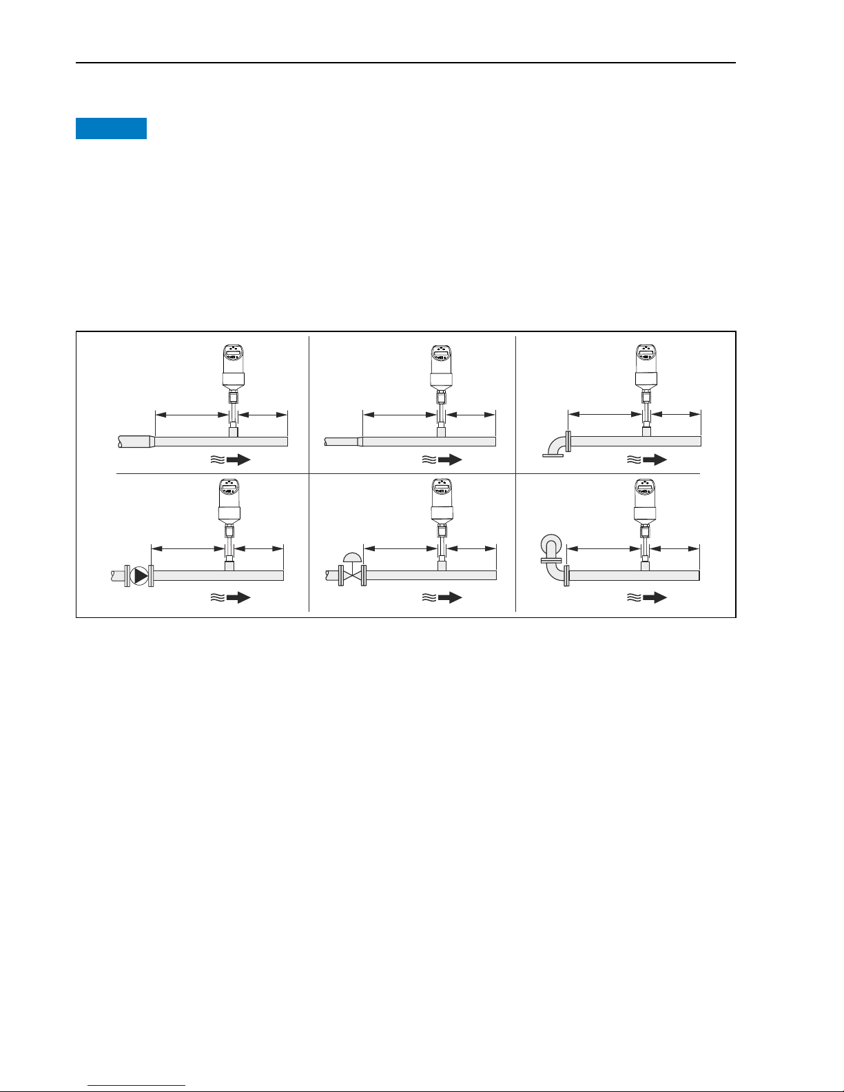
3.4.3 Inlet and outlet run
NOTICE
The thermal measuring principle is sensitive to disturbed flow conditions.
‣ As a general rule, install the measuring device as far away as possible from any flow
disturbances. For further information → ISO 14511.
‣ If possible, install the sensor upstream from fittings such as valves, T-pieces, elbows, etc.
‣ To attain the specified level of accuracy of the measuring device, the inlet and outlet runs
mentioned below must be maintained at the very minimum.
‣ If there are several flow disturbances present, the longest specified inlet run must be
maintained.
A0023225
Fig. 9: Inlet and outlet run
1Reduction
2Expansion
3 90° elbow or T-section
4Pump
5 Control valve
6 2x 90° elbow 2- or 3-dimensional
5 × DN
3 × DN
3 × DN
15 × DN
5 × DN
3 × DN
3 × DN
3 × DN
5 × DN
3 × DN
10 × DN
5 × DN
1
4
2
6
3
5
Page 13

DTT31, DTT35 Wiring
Endress+Hauser 13
4 Wiring
4.1 DC voltage version with M12x1 connector
A0006818
Flowphant T with M12x1 connector
A1: 1x PNP switch output
A2: 2x PNP switch outputs R1 and m (R2)
A2’: 2x PNP switch output R1 and m (diagnosis/NC contact for "DESINA" setting)
A3: 1x PNP switch output and 1x analog output (4 to 20 mA)
CAUTION
!
To avoid any damage to the analog input of a PLC, do not connect the active PNP switch output
of the device to the 4 to 20 mA input of a PLC.
DESINA (→ Chap. 5.1.6, basic settings):
R2 = diagnosis/NC contact (more information on DESINA can be found at www.desina.de).
NOTICE
Once connected to the power supply, the sensor tip of the device heats up! The temperature can
reach up to approx. 90 °C (194 °F).
DTT35: Electrical cables must comply with 3-A standard.
They must be smooth, corrosion resistant and cleanable.
4...20 mA
L–
L–
L–
L+
L+
L+
2
2
2
1
1
1
3
3
3
4
4
4
R1
m
R2
R1
A1
A2
A2’
A3
Page 14

Operation DTT31, DTT35
14 Endress+Hauser
4.2 DC voltage version with valve connector
P01-PTx3xxxx-04-xx-xx-xx-0 03
Fig. 10: Flowphant T with M16x1.5 valve connector or NPT ½"
B: 1x PNP switch output
5Operation
5.1 Onsite operation
The Flowphant T is operated by means of three keys. The digital display and the light emitting
diodes (LED) support navigation in the operating menu.
A0020825-EN
Fig. 11: Position of operating elements and possibilities for display
Operating keys
E
Communication jack
for personal computer
LED for status
Green = ok
Red = error/fault
LED red/green blinking = warning
Digital display
Illumination white (= ok)
Illumination red (= error/fault)
Yellow LEDs for switching states
LED on = switch closed
LED off = switch open
Page 15

DTT31, DTT35 Operation
Endress+Hauser 15
5.1.1 Navigating in the operating menu
T09-TTR31xxx-19-xx-xx-xx-0 02
Fig. 12: Navigating in the operating menu
A Function group selection
B Function selection
w
Enter the operating menu
–Press the E key for longer than 3 s
x
Select the "Function group" with the + or − key
y
Select the "Function" with the E key
z
Enter or change parameters with the + or − key
–Then return to "Function" with the E key Note: If software locking is enabled, it must be disabled before making
entries or changes
{
Return to the "Function group" by pressing the E key several times
–until the appropriate function group is reached again
|
Jump to the measuring position (Home position)
–Press the E key for longer than 3 s
}
Query to save data (select "YES" or "NO" with the + or − key)
–Confirm with the E key
Changes to the parameter settings only become effective if you choose s 'YES' when
asked to save data.
Page 16

Operation DTT31, DTT35
16 Endress+Hauser
5.1.2 Navigating the Calibration function group (CAL)
Variable limits for HIF (Learn High Flow) or LOWF (Learn Low Flow) can be configured using
the 'Learn' function.
• HIF configuration (Learn High Flow): Enter a random flow rate between 70% and 100% of the
maximum value in the process. The measuring device uses this value to automatically
calculate the corresponding 100% value.
• LOWF configuration (Learn Low Flow): Enter a random flow rate between 0% and 20% of the
maximum value in the process. The measuring device uses this value to automatically
calculate the corresponding 0% value.
A0010787
Fig. 13: Navigating the 'Learn' function using the Calibration (CAL) function group as an example
B Select function
w
Select the HIF (Learn High Flow) or LOWF (Learn Low Flow) function with the E key
C Select settings
x
Select the "RUN" function with the + key, 'Learn' function is initialized
y
Select the flow rate with the + key, press for longer than 2 s:
– If the HIF is configured (Learn High Flow), the upper flow rate (70% - 100%) is selected. Enter the current relative
flow rate in increments of 1% with the + or - key (factory setting 80%).
– If the LOWF is configured (Learn Low Flow), the lower flow rate (0% - 20%) is selected. Enter the current relative
flow rate in increments of 1% with the + or - key (factory setting 0%).
z
Select the "WAIT" function with the E key
{
Accept ('Learn') the current measured value after approx. 10 s - "OK" appears on the display
|
Or: The message "W432" appears on the display after 60 s
–A sufficiently stable flow rate was not detected during the learning process. The system takes an average of the 10
values last measured during the learning process.
}
Return to the CAL function group (Home position) with the E key
The device is still operative if message W432 appears. There can be large measuring
uncertainties however. Recommendation: Repeat 'Learn' process (points 1 to 4) until
"OK" appears on the display.
Page 17

DTT31, DTT35 Operation
Endress+Hauser 17
5.1.3 Navigating the 'Learn' switch point (SPL)
A0005785
Fig. 14: Navigating the 'Learn' switch point
B Select function
w
SPL ('Learn' switch point), optional SPL2 ('Learn' switch point 2) with the E key
C Select settings
x
Select the "RUN" function with the + key, 'Learn' function is initialized
y
Select the "WAIT" function with the + key, press for longer than 2 s
z
Accept ('Learn') the current measured value after approx. 10 s - "OK" appears on the display
{
Or: The message "W432" or "NOK" appears on the display after 60 s
–W432: A sufficiently stable flow rate was not detected during the learning process. The system takes an average of
the 10 values last measured during the learning process.
–NOK: The switch point determined is under 5% of the measuring range and cannot be accepted as the switch point
must be a min. of 5% greater than the switch-back point (RSP).
|
Return to the OUT function group (Home position) with the E key
The device is still operative if message "W432" or "NOK" appears.
However, large deviations at the switch point may result. Recommendation:
Repeat 'Learn' process (points 1 to 4) until "OK" appears on the display.
Page 18

Operation DTT31, DTT35
18 Endress+Hauser
5.1.4 Structure of the operating menu for 2 switch outputs
A0005784
Fig. 15: Operating menu: A function groups, B functions, C settings
Page 19

DTT31, DTT35 Operation
Endress+Hauser 19
5.1.5 Structure of the operating menu for 1 x analog output (4 to 20 mA) and
1 x switch output.
A0006819
Fig. 16: Operating menu: A function groups, B functions, C settings
Page 20

Operation DTT31, DTT35
20 Endress+Hauser
5.1.6 Basic settings
5.1.7 Calibration
Function
group
Function Settings Description
BASE
Basic
settings
DISP Display PV
PVRO
TMP
TMPR
OFF
OFFR
PV: displays the current measured value
PVRO: displays the current measured value rotated
180°
TMP: displays the current medium temperature
TMPR: displays the current medium temperature
rotated 180°
OFF: display off
OFFR: display off, rotated 180°
Factory setting: current measured value (PV)
UNIT Technical
unit
×C
×F
Display medium temperature unit °C or °F
Factory setting: °C
Only visible if the current medium
temperature TMP is selected in the DISP
mode.
TAU Damping 0.0 Measured value damping with regard to display
value and output: 0 (no damping) or 9 to 40 s (in
increments of 1 second)
Factory setting: 0 s
DESI DESINA
Only for 2 x
PNP switch
outputs
NO
YES
Behavior as per DESINA: PIN assignment of the M12
connector is in accordance with the guidelines of
DESINA
(DESINA = DistributEd and Standardized
INstAllation technology for machine tools and
manufacturing systems)
Factory setting: NO
Function
group
Function Settings Description
CAL
Calibration
HIF Learn High
Flow
RUN
WAIT
RUN, WAIT: setting for the maximum flow rate
occurring. 100% value (→ Page 16)
LOWF Learn Low
Flow
RUN
WAIT
RUN, WAIT: setting for the minimum flow rate
occurring. 0% value (→ Page 16)
Page 21

DTT31, DTT35 Operation
Endress+Hauser 21
5.1.8 Settings for output - 2 x switch output
Functions of the switch point
• Hysteresis function
The hysteresis function enables
two-point control via a hysteresis.
Depending on the mass flow, the
hysteresis can be set via the switch
point SP and the switch-back point
RSP.
A0005280
Fig. 17: m Hysteresis function, n NO contact, o NC contact
SP switch point; RSP switch-back point
• NO contact or NC contact
This switch function is freely
selectable.
• Delay times for switch point SP and
switch-back point can be set in
increments of 1 s. By this means
undesirable temperature peaks of
short duration or of high frequency
can be filtered out.
Function
group
Function Settings Description
OUT
Output 1
OUT2
Output 2,
optional
MODE Switching
mode
FLOW
TEMP
Output switching mode for channel 2
FLOW: flow rate or TEMP: temperature
Factory setting: FLOW
UNIT Technical
unit
×C
×F
Temperature unit selection °C or °F
Function only visible if the switching mode
MODE is set to temperature TEMP in the
2nd output.
Factory setting: °C
Page 22

Operation DTT31, DTT35
22 Endress+Hauser
OUT/
OUT2
continued
FUNC
FNC2
Switching
characteris
tics
HYNC
HYNO
HYNC: hysteresis/NC contact
HYNO: hysteresis/NO contact
(→ Fig. 17)
Factory setting: HYNO
SP
SP2
Switch
point value
0.0 • Enter value 5 to 100% in increments of 1%.
Factory setting: 50%
Or optionally for SP2:
• Enter value -15 to 85 °C (-5 to 185 °F) in
increments of
1 °C (1 °F) if the switching mode MODE is set to
temperature TEMP.
Factory setting: 55 °C
SPL
SP2L
Switch
point
’Learn’
RUN
WAIT
RUN, WAIT: take the current flow rate as the switch
point SP or SP2. See ’Navigating the Learn function’
(→ Fig. 13).
RSP
RSP2
Switchback
point value
0.0 • Enter value 0 to 95% in increments of 1%.
Factory setting: 40%
The value has to be at least 5% smaller
than the switch point (SP or SP2).
Or optionally for RSP2:
• Enter value -20 to 80 °C (-4 to 176 °F) in
increments of
1 °C (1 °F) if the switching mode MODE is set to
temperature TEMP.
Factory setting: 50 °C
Value has to be at least 5 °C (9 °F) smaller
than switch point 2 (SP2).
TSP
TSP2
Switch
point delay
0.0 Can be set anywhere between 0 and 99 s in
increments of 1 second.
Factory setting: 0 s
TRSP
TRSP2
Switchback
point delay
0.0 Can be set anywhere between 0 and 99 s in
increments of 1 second.
Factory setting: 0 s
Function
group
Function Settings Description
Page 23

DTT31, DTT35 Operation
Endress+Hauser 23
5.1.9 Settings for output - 1 x analog output (4 to 20 mA) and 1 x switch output
Function
group
Function Settings Description
4-20
Output 1
MODE Measurement
mode for
analog output
FLOW
TEMP
Output FLOW: flow rate or TEMP: temperature
For TEMP setting (temperature), the
measuring range is specified at -20 °C to
+85 °C (-4 °F to 185 °F).
Factory setting: FLOW
FCUR Error current MIN
MAX
HOLD
Current value in event of error:
MIN = ≤ 3.5 mA
MAX = ≥ 21.7 mA
HOLD = last current value
Factory setting: MAX
OUT
Output 2
MODE Switching
mode
FLOW
TEMP
Output switching mode FLOW: flow rate or TEMP:
temperature
Factory setting: temperature (TEMP)
UNIT Technical unit ×C
×F
Temperature unit selection °C or °F
Function only visible if the switching mode
MODE is set to temperature TEMP in the
2nd output.
Factory setting: °C
FUNC Switching
characteristics
HYNC
HYNO
HYNC: hysteresis/NC contact
HYNO: hysteresis/NO contact
(→ Fig. 17)
Factory setting: HYNO
SP Switch point
value
0.0 • Enter value 5 to 100% in increments of 1%.
Factory setting: 50%
or:
• Enter value -15 to 85 °C (-5 to 185 °F) in
increments of
1 °C (1 °F) if the switching mode MODE is set to
temperature TEMP.
Factory setting: 55 °C
SPL Switch point
’Learn’
RUN
WAIT
RUN, WAIT: take the current flow rate as the
switch point SP. See ’Navigating the Learn function’
(→ Page 16).
Page 24

Operation DTT31, DTT35
24 Endress+Hauser
OUT
continued
RSP Switchback
point value
0.0 • Enter value 0 to 95% in increments of 1%.
Factory setting: 40%
The value has to be at least 5% smaller
than the switch point SP.
or:
• Enter value -20 to 80 °C (-4 to 176 °F) in
increments of 1 °C (1 °F) if the switching mode
MODE is set to temperature TEMP.
Factory setting: 50 °C
Value has to be at least 5 °C (9 °F)
smaller than switch point SP2.
TSP Switch point
delay
0.0 Can be set anywhere between 0 and 99 s in
increments of 1 second.
Factory setting: 0 s
TRSP Switchback
point delay
0.0 Can be set anywhere between 0 and 99 s in
increments of 1 second.
Factory setting: 0 s
Function
group
Function Settings Description
Page 25

DTT31, DTT35 Operation
Endress+Hauser 25
5.1.10 Setting for service functions
Function
group
Function Settings Description
SERV
Service
functions
LOCK Locking
code
0 Enter the device locking code.
CODE Change
locking
code
0 User-defined code 1 to 9999;
0 = no locking;
Only visible if the locking code is valid.
PRES Reset NO
YES
Reset all entries to factory settings.
REV'
C
Static
revision
counter
0 Configuration counter, incremented each time the
configuration is changed.
STAT Device
status
LST'D Last error 0 Display of last error to occur.
Switch output
version
SIM
SIM2
Simulation
for 2 x
switch
output
OFF
OPEN
CLOS
OFF: no simulation
OPEN: switch output open
CLOS: switch output closed
Analog output
version (4 to 20
mA)
SIM
SIMA
Simulation
for 1 x
analog
output
(SIMA)
and 1 x
switch
output
(SIM)
OFF
OPEN
CLOS
3.5
4
8
...
OFF: no simulation
OPEN: switch output open
CLOS: switch output closed
3.5, 4, 8...:
Simulation values for analog output in mA
(3.5/4.0/8.0/12.0/16.0/20.0/21.7)
Page 26

Operation DTT31, DTT35
26 Endress+Hauser
5.2 Operation with PC and configuration software
A0008072
Fig. 18: Operation, visualization and maintenance with PC and configuration software.
Item 1: PC with ReadWin 2000 or Fieldcare configuration software
Item 2: Configuration kit TXU10-AA or FXA291 with USB port
Item 3: Flow switch
5.2.1 Additional operating options
In addition to the operating options listed in the previous "Onsite operation" section, the
ReadWin 2000 or FieldCare configuration software provides further information on the
Flowphant T:
Function group Function (display) Description
SERV (Service) Switching processes 1
Switching processes 2, optional
Number of changes in switching status for
switch output 1; optionally switch output 2
INFO
(device
information)
TAG 1
TAG 2
Tagging, 18-digit
Order code Order code
Device serial number -
Sensor serial number -
Electronics serial number -
Device revision Display of entire revision
Hardware revision -
Software revision -
Page 27

DTT31, DTT35 Maintenance
Endress+Hauser 27
5.2.2 Hints for the configuration with ReadWin 2000
Comprehensive information on the ReadWin 2000 configuration software may be found in the
Operating Instructions BA137R/09/en.
5.2.3 Hints for the configuration with FieldCare
FieldCare is an universal configuration software based on FDT/DTM technology.
NOTICE
To configure the Flowphant T DTT31/35 with FieldCare the “PCP (ReadWin) Communication
DTM” and the Flowphant Device-DTM are required.
The device supports only offline configuration and up-/download of parameters. The online
configuration is not supported.
Detailed information concerning FieldCare may be found in the operation manual (BA027S/c4)
or see: www.endress.com.
6 Maintenance
Any buildup on the sensor can have a negative effect on the accuracy. For this reason, check the
sensor for buildup at regular intervals.
CAUTION
!
Make sure the process is unpressurized before you remove the device! Do not twist the device
out of the process connection thread at the housing. Always use a suitable open-ended wrench
for disassembly work (see also → Fig. 5) (→ Chap. 3.3.1).
Page 28

Accessories DTT31, DTT35
28 Endress+Hauser
7 Accessories
All dimensions in the drawings are given in mm (in).
7.1 Welding bosses and coupling
7.1.1 Welding boss with sealing taper
7.1.2 Collar welding boss
7.1.3 Welding boss with sealing taper (metal - metal)
Collar welding boss moveable with sealing
taper and pressure screw;
material of parts in contact with the process:
316L, PEEK,
Max. process pressure 10 bar (145 psi)
Order number: 51004751
A0020709-EN
Material of parts in contact with process:
316L
Order no. 51004752
A0020710
Welding boss
Seal, metal-metal,
Material of parts in contact with process:
316L
Max. process pressure 16 bar (232 psi)
Order no. 60021387
A0006621
G½”
25 (0.98)
36 (1.42)
30 (1.18)
6 (0.24)
AF24
25 (0.98)
30 (1.18)
G½”
6 (0.24)
30 (1.18)
16 (0.63)
34 (1.34)
15 (0.6)
G½”
Page 29

DTT31, DTT35 Accessories
Endress+Hauser 29
7.1.4 Coupling
7.2 Electrical connection
7.2.1 Coupling; connecting cable
Moveable coupling, G½" process connection,
material coupling and parts in contact with
process: 316L
Order no. 51004753
A0020174-EN
Coupling M12x1; straight
Connection to M12x1 housing connector
Order number: 52006263
P01-PMP13xxx-00-xx-00-x x-003
Coupling M12x1 for own assembly of the
connecting cable; elbowed
Connection to M12x1 housing connector
Degree of protection (connected):
IP67, PG7
Order number: 51006327
A0020722
G½”
45 (1.77 )
15 (0.59)
6 (0.24)
+1
+0.04
AF14
AF27
20
(0.79)
41
(1.61)
35 (1.38)
14.8
(0.58)
Page 30

Accessories DTT31, DTT35
30 Endress+Hauser
7.3 Configuration kit
PVC cable, 4 x 0.34 mm2 (22 AWG) with
M12x1 coupling (assembled), elbowed,
screw plug, length 5 m (16.4 ft),
degree of protection: IP67
order number: 51005148
Core colors:
•1 = BN brown
•2 = WH white
•3 = BU blue
•4 = BK black
A0020723
PVC cable, 4 x 0.34 mm2 (22 AWG) with
M12x1 coupling, with LED, elbowed, 316L
screw plug, length 5 m (16.4 ft), especially
for hygiene applications,
degree of protection (connected): IP69K
order number: 52018763
Display:
− gn: device operational
− ye1: switch status 1
− ye2: switch status 2
Not suitable for 4 to 20 mA analog
output!
T09-TTR31xxx-00-00-xx-x x-001
• Configuration kit for PC-programmable
transmitters - ReadWin 2000 setup
program and interface cable (4 pin plug)
for PCs with USB port,
Order code: TXU10-AA
• Configuration kit "Commubox FXA291"
with interface cable for PCs with USB
port. Intrinsically safe CDI interface
(Endress+Hauser Common Data
Interface) for transmitters with 4-pole
post connector. Suitable device
configuration tool is e.g. FieldCare.
Order code: FXA291
A0008067
1
2 (WH) nc
2
1 (BN) +
4
3 (BU) -
3
4 (BK) nc
ye 1
ye 2 gn
Page 31

DTT31, DTT35 Accessories
Endress+Hauser 31
7.4 Configuration software
The ReadWin 2000 and FieldCare 'Device Setup' configuration programs can be downloaded free
of charge from the Internet at the following address:
• www.endress.com/readwin
• www.products.endress.com/fieldcare
FieldCare 'Device Setup' can also be ordered from an Endress+Hauser sales office.
Page 32

Troubleshooting DTT31, DTT35
32 Endress+Hauser
8 Troubleshooting
8.1 Error messages and warning messages
If an error occurs in the device, the color of the status LED changes from green to red and the
illumination of the digital display changes from white to red. A status LED flashing red and
green signals a warning. The display shows:
• E-code for errors
In the event of an error message, the measured value is uncertain.
• W-code for warnings
In the event of a warning, the measured value is reliable.
Code Explanation Remedy
E011 Device configuration faulty Reset device (→ Chap. 5.1.10)
E012 Error in measurement or medium temperature outside
measurable range
Check medium temperature, return device
to Endress+Hauser where necessary
E013 Sensor heating defective Return device to Endress+Hauser
E019 Power supply outside specification Check operating voltage
E015
Memory error Return device to Endress+HauserE020
E021
E022 Power is only supplied to the device via the
communication interface (measurement is deactivated)
Check operating voltage
E042 Output current can no longer be generated (only for 4
to 20 mA output, e.g. load at analog output too high or
open analog output)
Check load; switch off analog output
Page 33

DTT31, DTT35 Troubleshooting
Endress+Hauser 33
8.2 Repair
A repair is not planned.
8.3 Disposal
Please pay particular attention to the local disposal regulations of your country. When
disposing, ensure that the materials of the device components are separated and processed
accordingly.
Code Explanation Remedy
W107 Simulation active
W200 Fluid temperature outside specification
(> 85 °C)
Check fluid temperature and, where
necessary, adapt it to the specification
W202 Measured flow rate outside the range between set Low
and High Flow
(< -10% or > 110%)
Set High and Low Flow again, reset device
to factory setting where necessary (PRES
function)
W209 Device starts
W210 Configuration changed (warning code displayed for
approx. 15 s)
W240 Flow velocity too high (> 3 m/s in water), the device is
operated outside its specified measuring range. The
measurement is uncertain.
Reduce flow velocity of the medium
W250 Number of max. switch cycles exceeded
W260 Values for High Flow (HIF) and Low Flow (LOWF) too
close
Set High and Low Flow again (greater
distance apart), reset device to factory
setting where necessary (PRES function)
W270 Short-circuit and overload at output 1 Check output wiring
W280 Short-circuit and overload at output 2 Check output wiring
W432 Values for High Flow (HIF) or Low Flow (LOWF) could
not be determined with certainty (→ Page 16). The
device can be operated however.
Set High and Low Flow again (keep flow
velocity constant!)
Page 34

Troubleshooting DTT31, DTT35
34 Endress+Hauser
8.4 Change status (release)
The release number on the nameplate and in the Operating Instructions indicates the change
status of the device: XX.YY.ZZ (example 01.02.01).
8.5 Software history
XX Change in the main version.
Compatibility no longer provided. Device and Operating Instructions change.
YY Change in functionality and operation.
Compatibility provided. Operating Instructions change.
ZZ Troubleshooting and internal modifications.
Operating Instructions do not change.
Date Software version Software modifications Documentation
02.2006 01.00.00 Original
firmware
BA218r/09/en/02.06
(71022232)
12.2006 01.00.03 Analog output version
(4 to 20 mA) available
BA235r/09/en/12.06
(71036991)
12.2006 01.00.03 - BA235r/09/en/10.07
(71036991)
11.2008 01.00.04 Calibration function: Variable
configuration for HIF (70 to
100%) and LOWF (0 to 20%);
Warning message W200
BA235r/09/en/11.08
(71036991)
11.2008 01.00.04 - BA235r/09/en/06.09
(71098494)
11.2008 01.00.04 - BA235r/09/en/13.10
(71098494)
07.2013 01.00.08 - BA00235R/09/EN/14.13
(71226085)
01.2014 01.00.08 - BA00235R/09/EN/15.14
(71243850)
04.2014 01.00.08 - BA00235R/09/EN/16.14
(71252244)
Page 35

DTT31, DTT35 Technical data
Endress+Hauser 35
9Technical data
9.1 Power supply
Supply voltage
• DC voltage version 18 to 30 V DC
Current consumption
• < 100 mA (open-circuit operation) at 24 V DC, max. 150 mA (open-circuit operation); with
reverse polarity protection
Power supply failure
• Behavior in case of over voltage (> 30 V)
The device works continuously up to 34 V DC without any damage. No damage is caused to
the device in case of a short-term over voltage up to 1 kV (as per EN 61000-4-5). If the supply
voltage is exceeded, the properties specified are no longer guaranteed.
• Behavior in case of under voltage
If the supply voltage drops below the minimum value, the device switches off (status as if not
supplied with power = switch open).
9.2 Output
Switching capacity
• Switch status ON: I
a
≤ 250 mA
• Switch status OFF: Ia ≤ 1 mA
• Switching cycles: > 10,000,000
• Voltage drop PNP: ≤ 2 V
• Overload protection
Automatic load testing of switching current; output is switched off in event of over current,
the switching current is tested again every 0.5 s; max. capacitance load: 14 μF for max. supply
voltage (without resistive load); periodical protective disconnection in event of over current
(f = 2 Hz) and 'Warning' display.
Analog output: Signal on alarm as per NAMUR NE43
• Under ranging:
Linear drop to 3.8 mA
• Over ranging:
Linear rise to 20.5 mA
• Sensor breakage; sensor short-circuit:
≤ 3.6 mA or ≥ 21.0 mA (output 21.7 mA is guaranteed for setting ≥ 21.0 mA)
• Switch outputs: with safe status (switch open)
Page 36

Technical data DTT31, DTT35
36 Endress+Hauser
9.3 Operating conditions
• Orientation, → Chap. 3.4.1
• Top housing section can be rotated 310°
9.3.1 Operating conditions: Environment
• Ambient temperature range
–40 to +85 °C (-40 to 185 °F)
•Storage temperature
–40 to +85 °C (-40 to 185 °F)
•Climate class
4K4H as per DIN EN 60721-3-4
• Degree of protection
IP65 (optional IP66, depending on used connector)
• Shock resistance
50 g as per DIN IEC 68-2-27 (11 ms)
• Vibration resistance
20 g as per DIN IEC 68-2-6 (10-2000Hz)
4 g as per guidelines of German Lloyd GL
• Electromagnetic compatibility
Interference emission as per IEC 61326, class B equipment
Interference immunity as per IEC 61326, Appendix A (industry) and
NAMUR Recommendation NE21
EMC influence: ≤ 0.5%
9.3.2 Operating conditions: Process
• Process flow limits
Liquids: 0.03 to 3.0 m/s (0.1 to 9.84 ft/s)
• Process temperature limits
-20 to 85 °C (-4 to 185 °F)
The sensor can be exposed up to 130 °C (266 °F) without damage; monitoring switches off
automatically at T ≥ 85 °C (185 °F) and starts again at T ≤ 85 °C (185 °F).
• Process pressure limits
Maximum permitted process pressure p
max.
≤ 10 MPa = 100 bar (1450 psi)
NOTICE
The maximum process pressure for the conical metal-metal process connection (MB option)
for the DTT35 is 1.6 MPa = 16 bar (232 psi)!
Page 37

DTT31, DTT35 Technical data
Endress+Hauser 37
Page 38

Technical data DTT31, DTT35
38 Endress+Hauser
Page 39

DTT31, DTT35 Technical data
Endress+Hauser 39
Page 40

www.addresses.endress.com
 Loading...