

Page 1
BA00432C/07/EN/13.13
71207066
Products Solutions Services
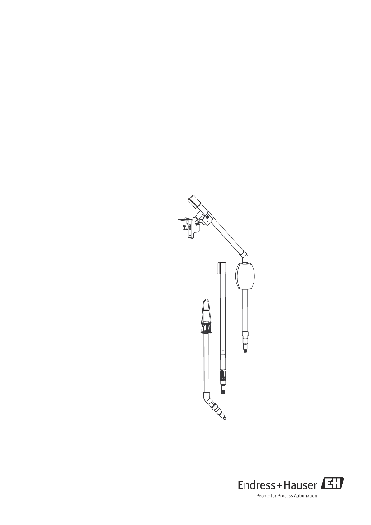
Operating Instructions
Flexdip CYA112
Wastewater assembly
Page 2
About this document
DANGER
!
WARNING
!
CAUTION
!
NOTICE
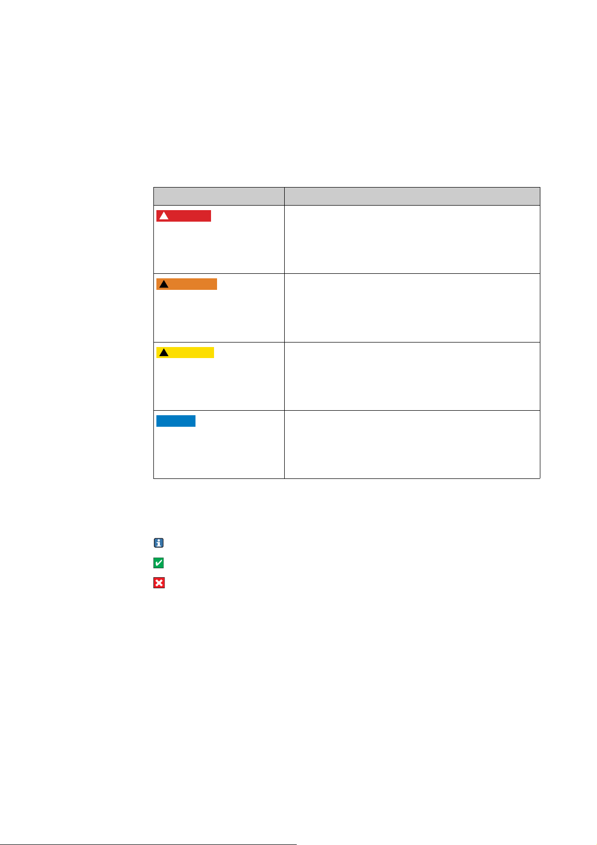
Safety messages
The structure, signal words and safety colors of the signs comply with the specifications of
ANSI Z535.6 ("Product safety information in product manuals, instructions and other
collateral materials").
Safety message structure Meaning
This symbol alerts you to a dangerous situation.
Cause (/consequences)
Consequences if safety
message is not heeded
‣ Corrective action
Cause (/consequences)
Consequences if safety
message is not heeded
‣ Corrective action
Cause (/consequences)
Consequences if safety
message is not heeded
‣ Corrective action
Failure to avoid the situation will result in a fatal or serious
injury.
This symbol alerts you to a dangerous situation.
Failure to avoid the situation can result in a fatal or serious
injury.
This symbol alerts you to a dangerous situation.
Failure to avoid this situation can result in minor or
medium injury.
Cause/situation
Consequences if safety
message is not heeded
‣ Action/note
Symbols
Additional information, tips
Permitted or recommended
Forbidden or not recommended
This symbol alerts you to situations that can result in
damage to property and equipment.
Endress+Hauser
Page 3

Flexdip CYA112
Table of contents
1 Basic safety instructions . . . . . . . . . . . . . 4
1.1 Requirements for the personnel . . . . . . . . . . . . . . . 4
1.2 Designated use . . . . . . . . . . . . . . . . . . . . . . . . . . . . . 4
1.3 Workplace safety . . . . . . . . . . . . . . . . . . . . . . . . . . . 4
1.4 Operational safety . . . . . . . . . . . . . . . . . . . . . . . . . . . 4
1.5 Product safety . . . . . . . . . . . . . . . . . . . . . . . . . . . . . . 4
2 Incoming acceptance and product
identification . . . . . . . . . . . . . . . . . . . . . . 5
2.1 Incoming acceptance . . . . . . . . . . . . . . . . . . . . . . . . 5
2.2 Scope of delivery . . . . . . . . . . . . . . . . . . . . . . . . . . . . 5
2.3 Product identification . . . . . . . . . . . . . . . . . . . . . . . . 5
2.4 Certificates and approvals . . . . . . . . . . . . . . . . . . . . 6
3 Installation . . . . . . . . . . . . . . . . . . . . . . . . 7
3.1 Installation conditions . . . . . . . . . . . . . . . . . . . . . . . 7
3.2 Installation instructions . . . . . . . . . . . . . . . . . . . . . . 8
3.3 Post-installation check . . . . . . . . . . . . . . . . . . . . . 15
4 Maintenance . . . . . . . . . . . . . . . . . . . . . . 16
4.1 Immersion pipe support . . . . . . . . . . . . . . . . . . . . 16
4.2 Maintaining the clamping systems and threads 16
4.3 Cleaning the quick fastener . . . . . . . . . . . . . . . . . 16
5 Repair . . . . . . . . . . . . . . . . . . . . . . . . . . . . 17
5.1 Return . . . . . . . . . . . . . . . . . . . . . . . . . . . . . . . . . . . 17
5.2 Disposal . . . . . . . . . . . . . . . . . . . . . . . . . . . . . . . . . 17
6 Accessories . . . . . . . . . . . . . . . . . . . . . . . 18
7 Technical Data . . . . . . . . . . . . . . . . . . . .28
7.1 Environment . . . . . . . . . . . . . . . . . . . . . . . . . . . . . 28
7.2 Process conditions . . . . . . . . . . . . . . . . . . . . . . . . . 28
7.3 Mechanical construction . . . . . . . . . . . . . . . . . . . 28
Index. . . . . . . . . . . . . . . . . . . . . . . . . . . . . 30
Endress+Hauser 3
Page 4

Basic safety instructions Flexdip CYA112
1 Basic safety instructions
1.1 Requirements for the personnel
‣ Installation, commissioning, operation and maintenance of the measuring system must
only be carried out by trained technical personnel.
‣ The technical personnel must be authorized by the plant operator to carry out the
specified activities.
‣ The electrical connection may only be performed by an electrical technician.
‣ The technical personnel must have read and understood these Operating Instructions
and must follow the instructions they contain.
‣ Measuring point faults may only be rectified by authorized and specially trained
personnel.
Repairs not described in the enclosed Operating Instructions may only be carried out
directly at the manufacturer's or by the service organization.
1.2 Designated use
CYA112 is designed as a modular assembly system for sensors in open basins, channels and
tanks.
Any other use than the one described here compromises the safety of persons and the entire
measuring system and is not permitted.
The manufacturer is not liable for damage caused by improper or non-designated use.
1.3 Workplace safety
As the user, you are responsible for complying with the following safety conditions:
• Installation instructions
• Local prevailing standards and regulations.
1.4 Operational safety
‣ Before commissioning the entire measuring point, make sure all the connections are
correct. Ensure that electrical cables and hose connections are not damaged.
‣ Do not operate damaged products, and safeguard them to ensure that they are not
operated inadvertently. Mark the damaged product as defective.
‣ If faults cannot be rectified, the products must be taken out of service and secured against
unintentional commissioning.
1.5 Product safety
The product is designed to meet state-of-the-art safety requirements, has been tested and
left the factory in a condition in which it is safe to operate. Relevant regulations and
European standards have been observed.
4 Endress+Hauser
Page 5

Flexdip CYA112 Incoming acceptance and product identification
2 Incoming acceptance and product
identification
2.1 Incoming acceptance
‣ Make sure the packaging is undamaged!
‣ Inform the supplier about any damage to the packaging.
Keep the damaged packaging until the matter has been settled.
‣ Make sure the contents are undamaged!
‣ Inform the supplier about damage to the contents. Keep the damaged products until the
matter has been settled.
‣ Check that the order is complete and agrees with your shipping documents.
‣ The packaging material used to store or to transport the product must provide shock
protection and humidity protection. The original packaging offers the best protection.
Also, keep to the approved ambient conditions (see "Technical data").
‣ If you have any questions, please contact your supplier or your local sales center.
2.2 Scope of delivery
The scope of delivery comprises:
• Ordered assembly version
• Operating Instructions, English.
If you have any questions, please contact your supplier or your local sales center.
2.3 Product identification
2.3.1 Nameplate
The nameplate contains the following information:
• Manufacturer data
•Order code
• Extended order code
• Serial number
• Operating conditions
•Safety icons
Compare the order code on the nameplate with your order.
2.3.2 Identifying the product
The order code and serial number of your device can be found in the following locations:
•On the nameplate
• In the delivery papers
To find out the version of your device, enter the order code indicated on the nameplate
in the search screen at the following address:
www.products.endress.com/order-ident
Endress+Hauser 5
Page 6

Incoming acceptance and product identification Flexdip CYA112
2.4 Certificates and approvals
Explosion protection
The stainless steel version of the CYA112 assembly (CYA112-*A21*2**) is suitable for use
in hazardous zones 1 and 2.
The ATEX directive 94/9/EC does not apply because the assembly has no potential ignition
source. Accordingly, it is not designated according to ATEX. Potential equalization must be
implemented as described in the chapter "Installation conditions".
If sensors have accessible metallic surfaces, these surfaces have to be connected to the
potential match according to the corresponding operating instructions.
6 Endress+Hauser
Page 7
Flexdip CYA112 Installation
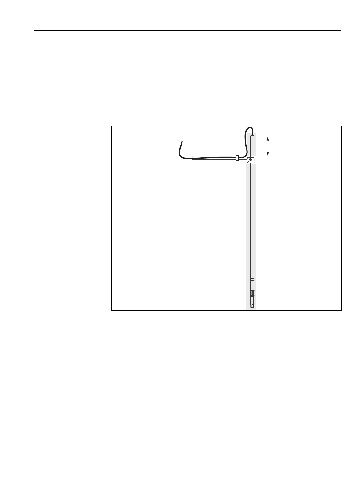
min. 100
(3.94)
mm (inch)
3Installation
3.1 Installation conditions
Install the assembly on a place with enough free space around it so the sensor cannot get
damaged.
When installing the assembly in a fixed position, make sure that it can be easily accessed and
maintained. The immersion pipe has to protrude the holding point by at least 100 mm
(3.94")
Fig. 1: Holding point (illustration without splash protection cap)
The grounding has to be done on-site. All conductive parts have to be connected to each
other.
For use in hazardous areas:
• The immersion pipe side of the assembly has to be conductively connected to the
corresponding holder or fixing.
• When the assembly is fixed via chain or mounting bracket a separate conductor for
potential match is needed beside the measuring cable.
• If sensors have accessible metallic surfaces, these surfaces have to be connected to the
potential match according to the corresponding operating instructions.
a0011037
Endress+Hauser 7
Page 8

Installation Flexdip CYA112
3.2 Installation instructions
3.2.1 Mounting the stainless steel parts
You have to screw the pipes together finger-tight (without any gaps). The threads are
lubricated and provided with an O-ring.
3.2.2 Gluing the PVC parts
PVC assemblies up to 1200 mm (47.2") in size are delivered as ready-to-install units
and do not have to be glued.
Where required, cleaning cloths and glues form part of the scope of supply.
Glue the PVC parts as follows:
1. Clean the surfaces to be glued (exterior pipe end, sleeve or internal angle piece) with the
cleaning cloth.
2. Allow the cleaned surfaces to dry for approx. 5 minutes.
3. Apply an even film of glue to the surfaces to be glued (sleeve first, then the pipe).
4. Join the parts within one minute (push together until the stop).
5. Remove the excess glue.
6. Allow the glued parts to harden for at least 5 minutes.
8 Endress+Hauser
Page 9
Flexdip CYA112 Installation
1
2
3
4
3.2.3 Mounting the sensor
Preparatory steps:
1. Screw or glue the connecting bracket onto the immersion tube.
2. Where necessary, screw the sensor adapter onto the connection bracket.
Mount the sensor as follows:
1. Guide the sensor cable through the immersion tube.
2. Where necessary, connect the sensor cable to the sensor.
3. Screw the sensor into the adapter or into the connection bracket. To prevent the sensor
cable from twisting, rotate the assembly and not the sensor.
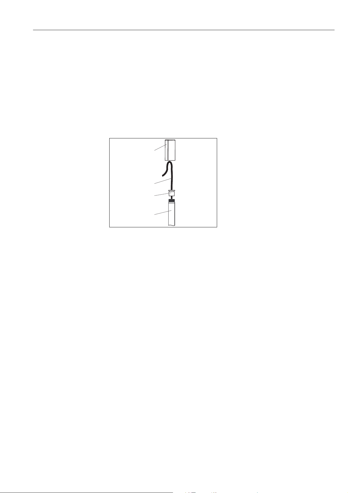
1
Splash protection cap
2
Sensor cable
3
Rubber plug
4
Immersion tube
a0011111
Fig. 2: Cable run
4. Shorten the tip of the rubber plug so that it suits the cable diameter.
5. Fit the rubber plug onto the sensor cable and press it onto the immersion tube.
6. Route the sensor cable downwards in a loop (do not bend) and fit on the splash
protection cap. The splash protection cap is fixed by the lip of the rubber plug.
Endress+Hauser 9
Page 10
Installation Flexdip CYA112
1
2
3
4
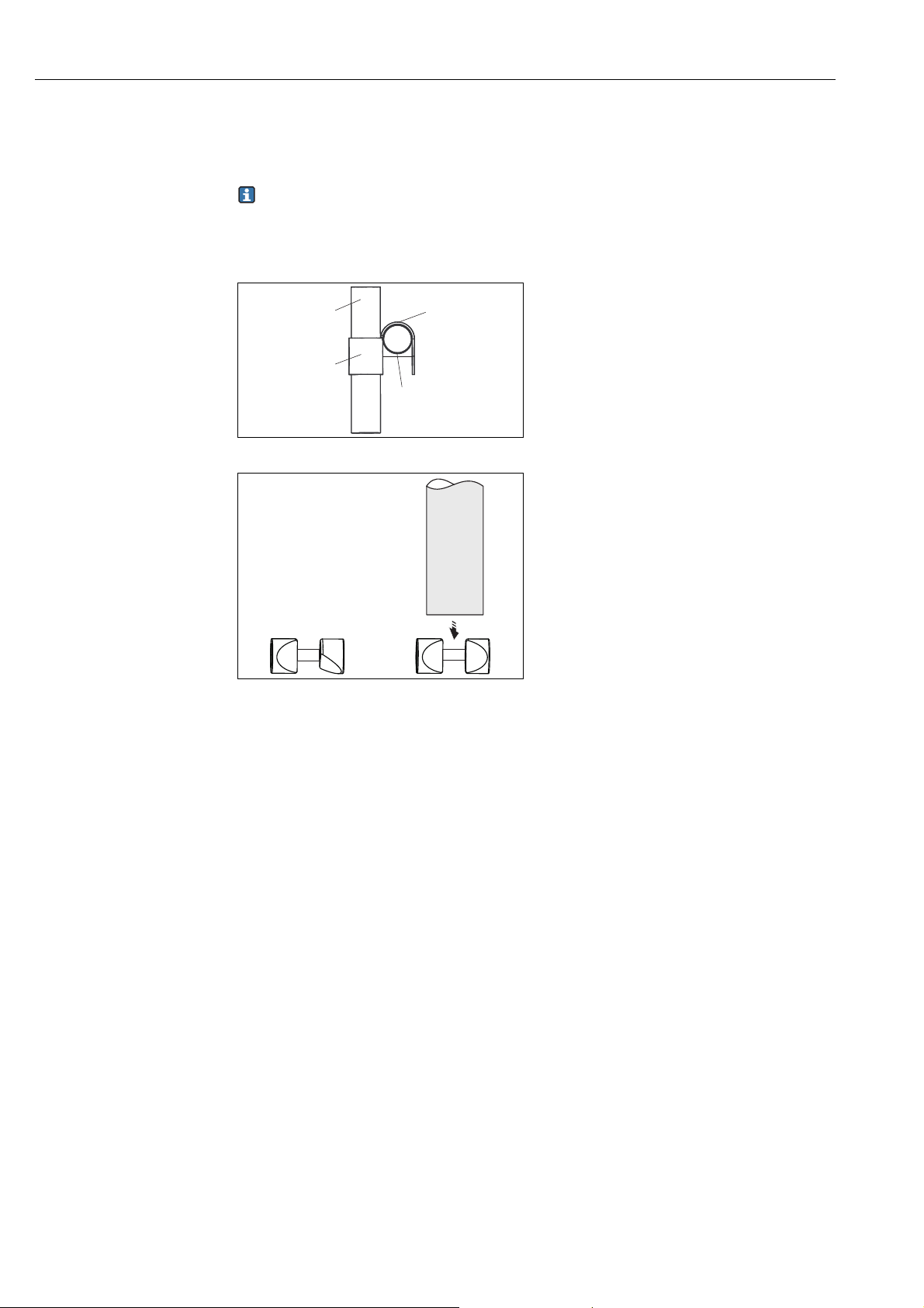
3.2.4 Fixed installation of the assembly on a transverse pipe
Prerequisite: The sensor is already mounted.
The cross clamp is mounted in such a way that one closed side points to the center of
the basin while the other closed side points upwards.
Mount the immersion tube as follows:
Immersion tube
1
Cross clamp, closed side to basin center
2
Cross clamp, closed side at top
Transverse pipe
3
4
a0011292
Fig. 3: Mounting the cross clamp
a0014991
Fig. 4: Adjustment of the clamps
1. Adjust the clamps on the cross clamp ( å 4).
2. Slide the cross clamp over the immersion tube. Make sure that the closed side of the
cross clamp is at the top ( å 3).
3. Mount the multifunctional clamp ring (funnel-shaped side facing upwards) on the
immersion tube above the cross clamp. The multifunctional clamp ring acts as an antislip lock.
4. Attach the cross clamp, along with the immersion tube, to the transverse pipe. Make
sure that the closed side of the cross clamp faces the basin ( å 3).
5. Align the assembly and the holder.
6. Tighten the clamp screws finger-tight (finger-tight corresponds to 13 Nm (9.6 lbf ft)).
10 Endress+Hauser
Page 11

Flexdip CYA112 Installation
1
2
3
4
3.2.5 Installation of the assembly on a chain retainer
Prerequisite:
• The immersion tube is fitted with a sensor.
• The transverse pipe is fitted with a chain.
Fig. 5: Mounting the chain retainer
1 Mount the multifunctional clamp ring
2 Loop the bracket into the chain
3 Attach the bracket to the multifunctional clamp ring
4 Fit the splash protection cap
x 60 to 80 mm (2.35 to 3.15 ")
1. Insert the weights into the immersion tube (only PVC immersion tubes).
2. Screw the multifunctional clamp ring onto the immersion tube (funnel-shaped side
facing downwards).
3. Guide the bracket into the lowest link in the chain.
4. Attach the bracket to the multifunctional clamp ring.
1
Splash protection cap
2
Sensor cable
3
Rubber plug
4
Immersion tube
a0011420
a0011111
Fig. 6: Cable run
5. Fit the rubber plug onto the sensor cable and press it onto the immersion tube.
6. Route the sensor cable downwards in a loop (do not bend) and fit on the splash
protection cap.
7. Secure the chain on the holder with the triangular carabiner and determine so the
maximum immersion depth of the assembly.
Endress+Hauser 11
Page 12

Installation Flexdip CYA112
3.2.6 Installation of the assembly with a float
a0011422
Fig. 7: Float mounting
1 Immersion tube with adhesive fitting and sensor adapter (finished ex works)
2Float body
3 Second immersion tube with 45° adhesive fitting
Preparatory steps
1. Slide the float body (item 2) onto the immersion tube (item 1).
2. Glue the second immersion tube (item 3) and the adhesive fitting (item 3) onto the
immersion tube (item 1) (see chapter "Gluing the PVC parts").
3. Adjust the clamps on the cross clamp.
4. Slide the cross clamp over the immersion tube. Make sure that the closed side of the
cross clamp is at the top.
5. Mount the multifunctional clamp ring (funnel-shaped side facing upwards) on the
immersion tube above the cross clamp. The multifunctional clamp ring acts as an antislip lock.
12 Endress+Hauser
Page 13

Flexdip CYA112 Installation
1
2
3
4
Installing the sensor and mounting the assembly
1. Guide the sensor cable through the immersion tube.
2. Where necessary, connect the sensor cable to the sensor.
3. Screw the sensor into the adapter. To prevent the sensor cable from twisting, rotate the
assembly and not the sensor.
1
Splash protection cap
2
Sensor cable
3
Rubber plug
4
Immersion tube
a0011111
Fig. 8: Cable run
4. Shorten the tip of the rubber plug so that it suits the cable diameter.
5. Fit the rubber plug onto the sensor cable and press it onto the immersion tube.
6. Mount the float assembly on the pendulum holder.
7. Align the assembly and the holder.
8. Tighten the clamp screws finger-tight (finger-tight corresponds to 13Nm (9.6 lbf ft)).
9. Route the sensor cable downwards in a loop (do not bend) and fit on the splash
protection cap. The splash protection cap is fixed by the lip of the rubber plug.
Endress+Hauser 13
Page 14

Installation Flexdip CYA112
1
2
3
4
3.2.7 Installation of the quick fastener
a0016947
Fig. 9: Quick fastener
1 Bore - makes it easier to screw the adapter tight
2Adapter
3 Thread adapter nut
4O-rings
Install the quick fastener as follows:
1. Provide both O-rings (item 4) with a thin film of lubricant.
2. Screw the adapter (item 2) into the immersion tube connection bracket.
3. Insert a screwdriver or a similar tool through the bores (item 1, serves as lever) to secure
the adapter.
4. Slide the thread adapter nut (item 3) over the adapter until the thread adapter nut
engages with a click.
5. Guide the sensor cable through the quick fastener and the immersion tube. The
Memosens coupling is secured in the quick fastener and cannot slip.
6. Connect the cable to the sensor.
7. The quick fastener allows to install the sensor without twisting the measuring cable.
Screw the sensor into the quick fastener until the stop. In doing so, turn the thread
adapter nut. Do not turn the sensor.
8. Align the sensor if necessary.
14 Endress+Hauser
Page 15

Flexdip CYA112 Installation
2
2
3
4
1
3
3.2.8 Dismount the quick fastener
Fig. 10: Dismounting the quick fastener
1 quick fastener - thread adapter nut
a0016950
Fig. 11: Dismounting the quick fastener
2 Connection clips
a0016951
Dismount the quick fastener as follows:
1. Move the thread adapter nut in the direction of the arrow to the stop position
( å 10). This pushes the connection clips towards the center ( å 11).
2. Stick the mounting tool onto the connection clips ( å 12) and push the mounting
tool very hard in the direction of the arrow.
3. The connection clips are unlocked. Pull off the thread adapter nut and the mounting
tool( å 13).
4. Unscrew the adapter from the immersion pipe.
a0016952
Fig. 12: Dismounting the quick fastener
3 Mounting tool
a0016953
Fig. 13: Dismounting the quick fastener
1 Quick fastener - thread adapter nut
3 Mounting tool
4 Quick fastener - adapter
3.3 Post-installation check
• After mounting, check whether all the screws are tightened correctly.
• If mounting using a pendulum holder, ensure the assembly has sufficient clearance.
Endress+Hauser 15
Page 16

Maintenance Flexdip CYA112
WARNING
!
4 Maintenance
There is a risk of infection when working with wastewater
‣ Wear protective gloves, goggles and protective clothing.
4.1 Immersion pipe support
a0011372
Fig. 14: Immersion tube tray for assembly service position
1 Immersion tube tray
The immersion tube tray makes it easier to perform maintenance tasks with rail mounting
involving a pendulum holder and cross clamp.
4.2 Maintaining the clamping systems and threads
Lubricate the clamping systems and threads at regular intervals.
Proceed as follows to do so:
1. Clean the clamps and threads with soapy water.
2. Dry the clamps and threads.
3. Provide the cleaned parts with a thin film of lubricant (e.g. Syntheso Glep1).
4.3 Cleaning the quick fastener
Preparatory steps:
1. Remove the sensor and cable.
2. Insert the removal tool (see "Accessories" section) into the thread adapter nut so that the
thread adapter nut is disengaged and can be removed.
Clean the quick fastener with soapy water.
16 Endress+Hauser
Page 17

Flexdip CYA112 Repair
5Repair
5.1 Return
The device must be returned if repairs or a factory calibration are required, or if the wrong
device has been ordered or delivered. According to legal regulations, Endress+Hauser, as an
ISO-certified company, is required to follow certain procedures when handling returned
products that are in contact with medium.
To ensure swift, safe and professional device returns, please read the return procedures and
conditions on the internet site:
www.services.endress.com/return-material
5.2 Disposal
Please dispose of the device in accordance with the local regulations.
Endress+Hauser 17
Page 18
Accessories Flexdip CYA112
6 Accessories
Multifunctional clamp ring
• Chain retainer in conjunction with the triangle carabiner
• Working height adjustment of the main pipe (version main pipe with transverse pipe)
• The multifunctional clamp ring acts as an anti-slip lock on transverse pipes, main pipes
and assemblies.
• Material: POM - GF
• Order No. 71092049
a0016879
Fig. 15: Multifunctional clamp ring
18 Endress+Hauser
Page 19

Flexdip CYA112 Accessories
Immersion pipe support
• Immersion pipe support for comfortable maintenance
• Material: stainless steel 1.4404 (AISI 316L)
• Order No. 71092054
a0016880
Fig. 16: Immersion pipe support
Endress+Hauser 19
Page 20

Accessories Flexdip CYA112
Wall mounting set
• 2 pipe clamps D 40; material: PE
• 1 worm-drive hose clip for height adjustment
• Order No.: 71132469
Fig. 17: Pipe clamp
Triangle carabiner
• Used to fix the chain (together with multifunctional clamp ring)
• Material: stainless steel
• Order No. 71092052
Fig. 18: Triangle carabiner
a0016767
a0016873
Hook-and-loop cable ties (set of 4 pieces)
• To fix the cables
• Material: PE / PA (polyethylene / polyamide)
• Order No. 71092051
20 Endress+Hauser
Page 21

Flexdip CYA112 Accessories
90 (3.54)
128 (5.04)
44.5 (1.75)
G 1
mm (inch)
Mounting tool
• Tool to remove the quick fastener
• Material: stainless steel
• Order No. 71093438
a0016305
Fig. 19: Mounting tool
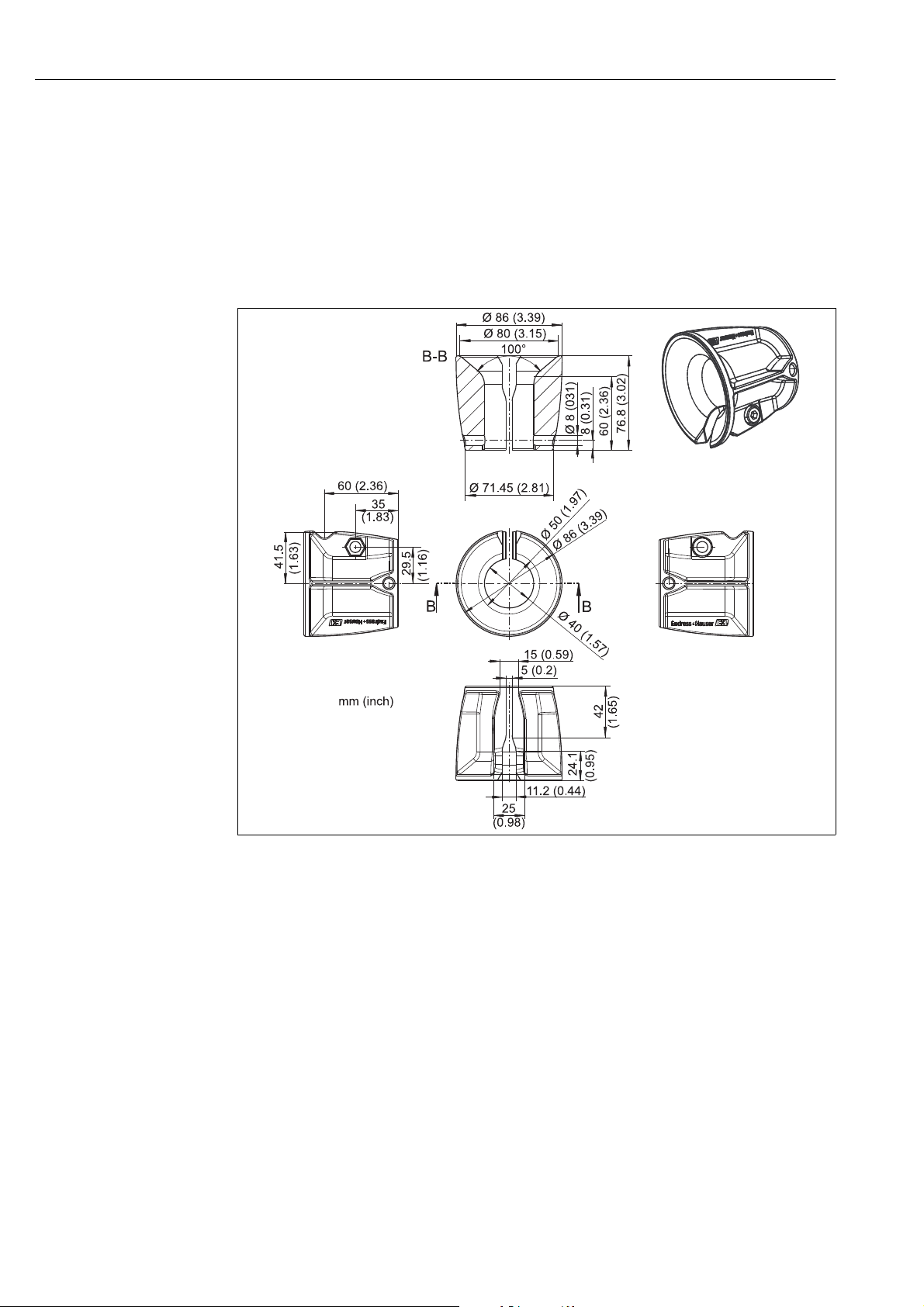
Quick fastener
• For the quick and easy installation and exchange of sensors
• Material: POM - GF
• Order No. 71093377
a0016286
Fig. 20: Quick fastener
Endress+Hauser 21
Page 22

Accessories Flexdip CYA112
Sensor adapter NPT ¾"
• Sensor adapter G1 to NPT ¾"
• Material: POM - GF
• Order No. 71093382
Fig. 21: Sensor adapter G1 to NPT¾"
Sensor adapter G¾
• Sensor adapter G1 to G¾
• Material: POM - GF
• Order No. 71093383
a0016285
a0016284
Fig. 22: Sensor adapter G1 to G¾
22 Endress+Hauser
Page 23

Flexdip CYA112 Accessories
Sensor adapter Pg 13.5
• Sensor adapter G1 to Pg 13.5
• Material: POM - GF
• Order No. 71093384
Fig. 23: Sensor adapter G1 to Pg 13.5
Immersion pipe
• Connection thread: M36
• Material: stainless steel
Fig. 24: Immersion pipe
• length x = 600 mm (23.6"): Order No. 71073767
• length x = 1200 mm (47.3"): Order No. 71073706
a0011169
a0011042
Endress+Hauser 23
Page 24

Accessories Flexdip CYA112
Immersion-pipe connection straight
• M36 to G1
• Material: stainless steel
• Order No. 71073768
a0016270
Fig. 25: Immersion-pipe connection straight
Immersion-pipe connection 45°
• M36 to G1
• Material: stainless steel
• Order No. 71073769
Fig. 26: Immersion-pipe connection 45°
a0016271
24 Endress+Hauser
Page 25

Flexdip CYA112 Accessories
Immersion-pipe connection 90°
• M36 to G1
• Material: stainless steel
• Order No. 71073770
Fig. 27: Immersion-pipe connection 90°
Protective cap
• Connection thread: M36
• Cable gland Pg 13.5
• Material: stainless steel
• Order No. 71115553
a0016273
a0016283
Fig. 28: Protective cap
Endress+Hauser 25
Page 26

Accessories Flexdip CYA112
271 (10.67)
Ø 99 (3.9)
44
(1.73)
129 (5.08)
Ø 74.3
(2.93)
Ø 41 (1.61)
1
2
3
mm (inch)
PVC protector for flexible mounting of CUS71D
• The PVC protector protects the ultrasonic sensor from getting damaged by the surface
skimmer.
• Order number: 71178584
Fig. 29: PVC protector for CUS71D
1 Assembly CYA112
2PVC-protector
3 Ultrasonic sensor CUS71D
a0016892
26 Endress+Hauser
Page 27

Flexdip CYA112 Accessories
CYA112 spray cleaning for installation on immersion pipe
• Versions in 600 mm and 1200 mm
• For assembly CYA112 version: 600 to 2400 mm, straight
• Material:
– Pipe: PVC-U
– Spacers: PA
– Worm drive hose clips: stainless steel 1.4401 (AISI 316)
• Order No. for 600 mm - version: 71158245
• Ordet No. for 1200 mm - version: 71158246
Fig. 30: Spray cleaning for CYA112
A Version: 1200 mm
B Version: 600 mm
Fig. 31: Example of an installed spray cleaning
a0017182
a0017805
Endress+Hauser 27
Page 28

Technical Data Flexdip CYA112
7Technical Data
7.1 Environment
Air temperature -20 to +60 °C (-4 to 140 °F)
7.2 Process conditions
Process temperature
range
Process pressure range unpressurized
0 to 60 °C (32 to 140 °F)
7.3 Mechanical construction
Dimensions
Weight
Materials
Immersion pipe (PVC): Ø 40 mm (1.57"), length: 600, 1200, 1800 and 2400 mm
Immersion pipe (stainless steel): Ø 40 mm (1.57"), length: 600, 1200, 1800, 2400 and
Immersion pipe (stainless steel)
(length 1 / 2 / 3 / 4 / 5):
Immersion pipe (PVC)
(length 1 / 2 / 3 / 4): 0.3 / 0.6 / 0.95 / 1.3 kg (0.7 / 1.4 / 2.1 / 2.8 lbs)
Multifunctional clamp ring: 0.15 kg (0.33 lbs)
Weights for immersion pipe
(PVC): 0.32 kg (0.71 lbs)
Immersion pipe: stainless steel 1.4404 (AISI 316 L)
Connection angle: stainless steel 1.4404 (AISI 316 L)
Welded threads stainless steel 1.4571 (AISI 316 Ti)
Sensor adaption: POM - GF
Quick fastener: POM - GF
Multifunctional clamp ring: POM - GF
Cap: PE
Chain bracket: stainless steel 1.4571 (AISI 316 Ti) or 1.4404 (AISI
O-rings: EPDM
Floater, yellow: PVC (up to middle of 2012)
Floater, black: EPP (from middle of 2012 on)
(23.6", 47.2", 70.9" and 94.5")
3600 mm (23.6", 47.2", 70.9", 94.5" and 142")
0.6 / 1.2 / 1.8 / 2.4 / 3.5 kg (1.3 / 2.6 / 4.0 / 5.3 /
10.8 lbs)
316 L)
28 Endress+Hauser
Page 29

Flexdip CYA112 Technical Data
Endress+Hauser 29
Page 30

Flexdip CYA112
Index
A
Accessories . . . . . . . . . . . . . . . . . . . . . . . . . . . . . . . . . . . . . 18
C
Checking
Installation . . . . . . . . . . . . . . . . . . . . . . . . . . . . . . . . . . 15
D
Designated use. . . . . . . . . . . . . . . . . . . . . . . . . . . . . . . . . . . . 4
Dismount the quick fastener . . . . . . . . . . . . . . . . . . . . . . 15
F
Fixed installation on transverse pipe . . . . . . . . . . . . . . . 10
Float
Installation . . . . . . . . . . . . . . . . . . . . . . . . . . . . . . . . . . 12
G
Gluing the PVC parts . . . . . . . . . . . . . . . . . . . . . . . . . . . . . . . 8
I
Immersion pipe support . . . . . . . . . . . . . . . . . . . . . . . . . . 16
Incoming acceptance. . . . . . . . . . . . . . . . . . . . . . . . . . . . . . . 5
Installation . . . . . . . . . . . . . . . . . . . . . . . . . . . . . . . . . . . . 7–8
Assembly on chain retainer . . . . . . . . . . . . . . . . . . . . 11
Fixed installation on transverse pipe . . . . . . . . . . . . 10
Float. . . . . . . . . . . . . . . . . . . . . . . . . . . . . . . . . . . . . . . . 12
PVC parts . . . . . . . . . . . . . . . . . . . . . . . . . . . . . . . . . . . . . 8
Quick fastener . . . . . . . . . . . . . . . . . . . . . . . . . . . . . . . 14
Sensor . . . . . . . . . . . . . . . . . . . . . . . . . . . . . . . . . . . . . . . . 9
Stainless steel pipes. . . . . . . . . . . . . . . . . . . . . . . . . . . . . 8
S
Scope of delivery . . . . . . . . . . . . . . . . . . . . . . . . . . . . . . . . . . 5
Sensor installation . . . . . . . . . . . . . . . . . . . . . . . . . . . . . . . . 9
Stainless steel pipes
Installation . . . . . . . . . . . . . . . . . . . . . . . . . . . . . . . . . . . . 8
T
Technical Data . . . . . . . . . . . . . . . . . . . . . . . . . . . . . . . . . . . 28
U
Use . . . . . . . . . . . . . . . . . . . . . . . . . . . . . . . . . . . . . . . . . . . . . 4
W
Workplace safety. . . . . . . . . . . . . . . . . . . . . . . . . . . . . . . . . . 4
M
Maintenance . . . . . . . . . . . . . . . . . . . . . . . . . . . . . . . . . . . 16
N
Nameplate . . . . . . . . . . . . . . . . . . . . . . . . . . . . . . . . . . . . . . . 5
O
Operational safety . . . . . . . . . . . . . . . . . . . . . . . . . . . . . . . . . 4
P
Product identification . . . . . . . . . . . . . . . . . . . . . . . . . . . . . . 5
Product safety . . . . . . . . . . . . . . . . . . . . . . . . . . . . . . . . . . . . 4
Q
Quick fastener
Dismount . . . . . . . . . . . . . . . . . . . . . . . . . . . . . . . . . . . 15
Installation . . . . . . . . . . . . . . . . . . . . . . . . . . . . . . . . . . 14
R
Repair . . . . . . . . . . . . . . . . . . . . . . . . . . . . . . . . . . . . . . . . . 17
Requirements for the personnel . . . . . . . . . . . . . . . . . . . . . 4
Return . . . . . . . . . . . . . . . . . . . . . . . . . . . . . . . . . . . . . . . . . 17
30 Endress+Hauser
Page 31

Flexdip CYA112
Endress+Hauser 31
Page 32

www.addresses.endress.com
71207066
 Loading...