

Page 1
Products Solutions Services
BA00071S/04/en/03.13
Product Version 1.01.xx
71213933
Operating Instructions
Fieldgate SFG500
Operation as Access Point
8
Power
Run
Failure
RS485
LAN 1
LAN 2
PB DP
PB Err
Reset
SFG500
LAN 1
LAN 2
Page 2

Page 3

Fieldgate SFG500
Endress+Hauser 1
Table of Contents
Revision History . . . . . . . . . . . . . . . . . . . . . . . . . . . . 2
Registered Trademarks . . . . . . . . . . . . . . . . . . . . . . 2
1 Safety . . . . . . . . . . . . . . . . . . . . . . . . . . . . . 3
1.1 Designated use . . . . . . . . . . . . . . . . . . . . . . . . . . . . . 3
1.2 Installation, commissioning and operation . . . . . . 3
1.3 Operational safety . . . . . . . . . . . . . . . . . . . . . . . . . . . 3
1.4 Supplementary documentation . . . . . . . . . . . . . . . . 3
1.5 Conventions and icons . . . . . . . . . . . . . . . . . . . . . . . 4
2 Function and System Design . . . . . . . . . 5
2.1 Function . . . . . . . . . . . . . . . . . . . . . . . . . . . . . . . . . . . 5
2.2 System design . . . . . . . . . . . . . . . . . . . . . . . . . . . . . . 5
3 Commissioning. . . . . . . . . . . . . . . . . . . . . 6
3.1 Preliminaries . . . . . . . . . . . . . . . . . . . . . . . . . . . . . . . 6
3.1.1 Computer IP properties . . . . . . . . . . . . . . . . 6
3.1.2 Web browser . . . . . . . . . . . . . . . . . . . . . . . . . 7
3.2 IP address of LAN1 port . . . . . . . . . . . . . . . . . . . . . . 8
3.2.1 Fieldgate SFG500 IP address . . . . . . . . . . . 8
3.2.2 IP address of the FieldCare computer . . . . 8
3.3 Fieldgate SFGNetwork DTM . . . . . . . . . . . . . . . . . . 9
3.3.1 Installing the SFGNetwork DTM . . . . . . . . 9
3.3.2 Update the FieldCare DTM catalog . . . . . . 9
4 FieldCare . . . . . . . . . . . . . . . . . . . . . . . . . 10
4.1 Single segment with Pepperl+Fuchs coupler . . . 10
4.1.1 Architecture . . . . . . . . . . . . . . . . . . . . . . . 10
4.1.2 Create a FieldCare project . . . . . . . . . . . . 11
4.1.3 Add the SFGNetwork CommDTM . . . . . 12
4.1.4 Scan for Fieldgate SFG500 . . . . . . . . . . . 13
4.1.5 Scan for devices . . . . . . . . . . . . . . . . . . . . 14
4.1.6 Open a device DTM . . . . . . . . . . . . . . . . . 15
4.1.7 Store the project . . . . . . . . . . . . . . . . . . . . 16
4.2 Multiple segments with transparent couplers . . 17
4.2.1 Architecture . . . . . . . . . . . . . . . . . . . . . . . 17
4.2.2 Create a FieldCare project . . . . . . . . . . . . 18
4.2.3 Add the SFGNetwork CommDTM . . . . . 18
4.2.4 Scan for Fieldgate SFG500 . . . . . . . . . . . 18
4.2.5 Scan for devices . . . . . . . . . . . . . . . . . . . . 19
4.3 Segment with Siemens link . . . . . . . . . . . . . . . . . 20
4.3.1 Architecture . . . . . . . . . . . . . . . . . . . . . . . 20
4.3.2 Create a FieldCare project . . . . . . . . . . . . 21
4.3.3 Add the SFGNetwork CommDTM . . . . . 21
4.3.4 Scan for Fieldgate SFG500 . . . . . . . . . . . 21
4.3.5 Scan for the Coupler/Link . . . . . . . . . . . . 22
4.3.6 Scan for devices . . . . . . . . . . . . . . . . . . . . 23
4.4 Segment with Stahl Remote I/O . . . . . . . . . . . . . 24
4.4.1 Architecture . . . . . . . . . . . . . . . . . . . . . . . 24
4.4.2 Create a FieldCare project . . . . . . . . . . . . 25
4.4.3 Add the SFGNetwork CommDTM . . . . . 25
4.4.4 Scan for Fieldgate SFG500 . . . . . . . . . . . 25
4.4.5 Scan for the Coupler/Link . . . . . . . . . . . . 26
4.4.6 Scan for devices . . . . . . . . . . . . . . . . . . . . 27
5 DTM for Fieldgate SFG500. . . . . . . . . . 28
5.1 Configuration . . . . . . . . . . . . . . . . . . . . . . . . . . . . 28
5.1.1 Fieldgate SFG500 CommDTM . . . . . . . . 28
5.1.2 Proxy Server Configuration . . . . . . . . . . . 29
5.2 Embedded Web Server . . . . . . . . . . . . . . . . . . . . . 30
5.2.1 PROFIBUS live list . . . . . . . . . . . . . . . . . . 31
5.2.2 PROFIBUS Monitor . . . . . . . . . . . . . . . . . 33
5.2.3 PROFIBUS Settings . . . . . . . . . . . . . . . . . . 34
5.2.4 Slave Settings . . . . . . . . . . . . . . . . . . . . . . 36
5.2.5 Settings and Information tabs . . . . . . . . 37
5.3 Additional Functions . . . . . . . . . . . . . . . . . . . . . . 38
5.3.1 Communication log . . . . . . . . . . . . . . . . . 38
5.3.2 Set Device Address (PB Address) . . . . . . 39
5.3.3 Set DTM Address (DTM) . . . . . . . . . . . . . 40
5.3.4 Help . . . . . . . . . . . . . . . . . . . . . . . . . . . . . . 41
5.3.5 About . . . . . . . . . . . . . . . . . . . . . . . . . . . . . 41
6 Trouble-Shooting . . . . . . . . . . . . . . . . . 42
6.1 FieldCare . . . . . . . . . . . . . . . . . . . . . . . . . . . . . . . . 42
Appendix A Changing a computer’s
IP properties. . . . . . . . . . . . . . . . . . . . . . 43
Appendix B Windows Firewall . . . . . . . . . . . 45
Index . . . . . . . . . . . . . . . . . . . . . . . . . . . . 48
Page 4

Fieldgate SFG500
2 Endress+Hauser
Revision History
Registered Trademarks
PROFIBUS
®
Registered trademark of the PROFIBUS User Organisation, Karlsruhe Germany.
MODBUS
®
Registered trademark of MODBUS IDA, Hopkinton, MA, USA.
Microsoft
®
, Windows®, Windows 2000®, Windows XP®, Windows 2003 Server®, Windows
2008 Server
®
,Windows 7®, Windows Vista® and the Microsoft logo are registered
trademarks of the Microsoft Corporation.
Acrobat Reader
®
is a registered trade mark of the Adobe Systems Incorporated.
All other brand and product names are trademarks or registered trademarks of the
companies and organizations in question
Product
version
Manual Changes Remarks
1.00.xx BA00071S/04/en/01.11 Original manual
1.00.xx BA00071S/04/en/02.12 Editorial Chapter 3 IP LAN1: 10.126.84.100
Chapter 5.1.1
Chapter 5.3.4
Chapter 5.3.5
New DTM function: PROFIBUS Scan Range
New DTM function: Set Device Address
Addition text concerning new function
General Renumbering, TOC, Index
1.01.xx BA00071S/04/en/03.13 Chapt
er 5
Chapter 5
.2
Chapter 5.3
Screenshots and texts updated
Embedded Web Server added
Additional functions restructured
Update New CD
Page 5

Fieldgate SFG500 Safety
Endress+Hauser 3
1Safety
1.1 Designated use
Fieldgate SFG500 is a system component that provides an independent access route to a
PROFIBUS network. It may be used in a variety of applications that are supported by specific
operating modes. The operating modes are determined by an optional memory card
(Fieldgate Module SFM500).
Without memory card, Fieldgate SFG500 has the basic operating mode Access Point. In this
case, it acts as an Ethernet gateway with adaptive PROFIBUS Master Class 2 capabilities to
support FDT-based plant asset management host applications, e.g. FieldCare. The various
operating modes are described in their respective manuals, see Chapter 1.4.
1.2 Installation, commissioning and operation
Fieldgate SFG500 has been designed to operate safely in accordance with current technical
safety and EU directives. Field devices, links, junction boxes, cables and other hardware used
in conjunction with the Fieldgate SFG500 module must also be designed to operate safely in
accordance with current technical safety and EU directives.
If devices are installed incorrectly or used for applications for which they are not intended,
or if the Fieldgate SFG500 module is not configured correctly, it is possible that dangers may
arise. For this reason, the system must be installed, connected, configured, operated and
maintained according to the instructions in this and the associated manuals: personnel must
be authorised and suitably qualified.
1.3 Operational safety
When using Fieldgate SFG500 as an Access Point, the instructions in Chapter 1.3 of
BA0070S/04/en, Fieldgate SFG500: Installation and Commisioning, shall be observed.
1.4 Supplementary documentation
Table 1-1 indicates the documents, planned and realized, containing safety relevant
information, installation, commissioning and operating instructions for Fieldgate SFG500.
This manual decribes the use of Fieldgate SFC500 as a access point, i.e. without memory
card. The configuration of Fieldgate SFG500 for each of its various operating modes is
described in a separate manual.
The manual PROFIBUS guidelines contains information on how to design and install a
PROFIBUS network, in particular on how to ground the network in order to avoid
electromagnetic interference on the bus.
All documentation available at the time of release is included on the Fieldgate SFG500 CDROM and can be installed by default in Start=>Programs=>Endress+Hauser=Fieldgate
SFG500=>Manuals from it.
Tab. 1-1: Fieldgate SFG500 Documentation
Description Document type Designation Order No.
Fieldgate SFG500; Installation and Commissioning Operating manual BA00070S/04/en 71213935
Fieldgate SFG500; Operation as Access Point Operating manual BA00071S/04/en 71213933
Fieldgate SFG500; Operation as Asset Monitor Operating manual BA00072S/04/en 71142837
Fieldgate SFG500; Operation as Process Monitor Operating manual BA00074S/04/en –
Fieldgate SFG500; Getting Started Operating manual BA00073S/04/a2 71213929
PROFIBUS Guidelines Operating manual BA00034S/04/en 56004242
Page 6
Safety Fieldgate SFG500
4 Endress+Hauser
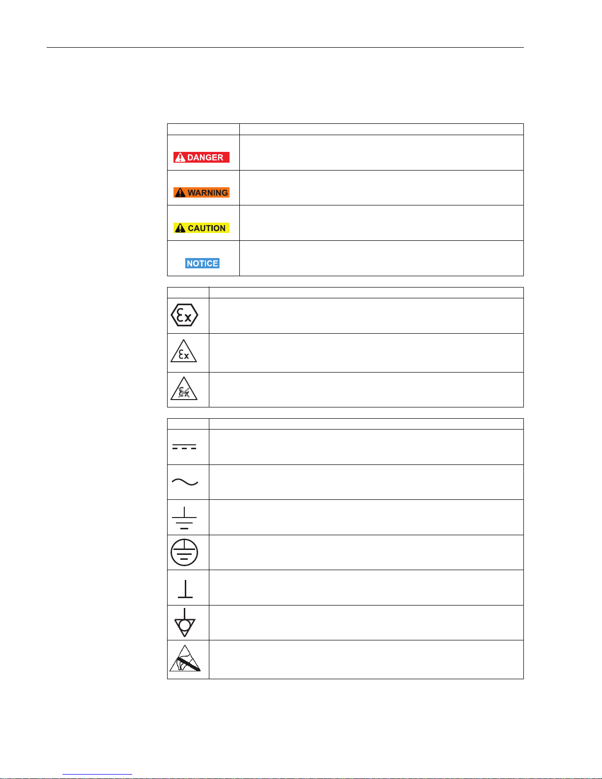
1.5 Conventions and icons
In order to highlight safety relevant or alternative operating procedures in the manual, the
following conventions have been used, each indicated by a corresponding icon in the margin.
Safety conventions
Explosion protection
Electrical symbols
Icon Meaning
DANGER!
This symbol alerts you to a dangerous situation. Failure to avoid this situation will result
in serious or fatal injury.
WARNING!
This symbol alerts you to a dangerous situation. Failure to avoid this situation can result
in serious or fatal injury.
CAUTION!
This symbol alerts you to a dangerous situation. Failure to avoid this situation can result
in minor or medium injury.
NOTE!
This symbol contains information on procedures and other facts which do not result in
personal injury.
Icon Meaning
Device certified for use in explosion hazardous area
If the device has this symbol embossed on its name plate it can be installed in an explosion
hazardous area in accordance with the specifications in the certificate or in a safe area
Explosion hazardous area
Symbol used in drawings to indicate explosion hazardous areas. Devices located in and wiring
entering areas with the designation “explosion hazardous areas” must conform with the stated type
of protection
Safe area (non-explosion hazardous area)
Symbol used in drawings to indicate, if necessary, non-explosion hazardous areas. Devices located
in safe areas still require a certificate if their outputs run into explosion hazardous areas.
Icon Meaning
Direct voltage
A terminal to which or from which a direct current or voltage may be applied or supplied
Alternating voltage
A terminal to which or from which an alternating (sine-wave) current or voltage may be applied or
supplied
Grounded terminal (FE)
A grounded terminal, which as far as the operator is concerned, is already grounded by means of an
earth grounding system
Protective grounding (earth) terminal
A terminal which must be connected to earth ground prior to making any other connection to the
equipment
Signal ground (GND)
A terminal on to which the shield of a signal cable can be connected
Equipotential connection (earth bonding)
A connection made to the plant grounding system which may be of type e.g. neutral star or
equipotential line according to national or company practice
Electrostatic discharge
A terminal or location at which an electrostatic discharge might cause damage to the module
circuitry
Page 7
Fieldgate SFG500 Function and System Design
Endress+Hauser 5
2 Function and System Design
2.1 Function
When no Fieldgate Module SFM500 is inserted in the Fieldgate SFG500’s memory card slot,
it acts as an Access Point. In this mode, it provides a parallel path to a PROFIBUS DP network
and is used together with FieldCare, Endress+Hauser’s plant asset management system. The
SFGNetwork DTM is provided for use with FieldCare and offers the following functions:
• Scanning for all Fieldgate SFG500s in the same Ethernet IP address domain
• Scanning for all PROFIBUS DP/PA devices in the connected segment
• Access to the functions embedded in the web server, e.g. live list, settings etc.
The DTM is supplied as standard with FieldCare version 2.09.xx or can be installed from the
Set-up CD ROM provided with Fieldgate SFG500.
2.2 System design
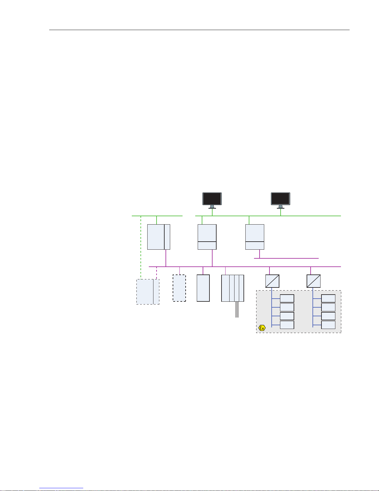
Fig. 2.1 shows Fieldgate SFG500 operating as an Access Point in a PROFIBUS network.
Fig. 2-1: System architecture for Fieldgate SFG500 operating as an access point
The control network comprises one or more PLCs or DCSs and one or more PROFIBUS DP
segments. Connected to the PROFIBUS DP segment are PROFIBUS DP slaves, Remote I/Os
and segment couplers or links. Through its Ethernet port (LAN1), Fieldgate SFG500 allows
FieldCare access to access a PROFIBUS DP segment. If there is more than one segment in the
PROFIBUS DP network, a separate Fieldgate SFG500 is required for each.
Fieldgate SFG500 can be configured by a web browser, e.g. Internet Explorer, from any
computer in the local area network or via its second Ethernet port (LAN2). In the latter case,
Fieldgate SFG500’s DHCP server will supply an IP address to the connected computer.
PLC/
DCS
PB Master Class 1
PLC/
DCS
PB Master Class 1
Listener
PB MS 2
SFG500
Listener
PB MS 2
SFG500
N<255
PB Master Class 2
(visitor)
DP Slave
(PA profile)
DP RIO
(HART Connectivity)
HART master
HART
(point-to-point)
DP/PA Coupler
Ex-version
(transparent)
DP/PA Link
Ex-version
(opaque)
PA Slave
PA Slave
PA Slave
PA Slave
PA Slave
PA Slave
PA Slave
PA Slave
Additional
PB Master Class 1
(optional)
PROFIBUS PA
PROFIBUS PA
Control Network LAN 1 (Ethernet)
PROFIBUS DP (Segment 1)
PROFIBUS DP (Segment n)
FieldCare Web-Browser
Page 8

Commissioning Fieldgate SFG500
6 Endress+Hauser
3 Commissioning
NOTE!
• This section describes the steps to physically commission Fieldgate SFG500 for use as a
access point only.
• General commissioning for use is described in BA00070S/04/en, Fieldgate SFG500:
Installation and Commissioning, commisioning for other modes in the associated manual,
see Chapter 1.4.
• The manual assumes that the Fieldgate battery has been inserted and the network is up
and running.
3.1 Preliminaries
3.1.1 Computer IP properties
The LAN1 and LAN2 interfaces of Fieldgate SFG500 allow communication with a computer
via the integral Web Server. Before starting, check the following:
• Internet Protocol TCP/IP is installed on your computer and is active
• You have administration rights for your computer and network
• You have an set of IP addresses that have been authorized by your IT department
• Any proxy server for your Internet Browser is disabled
Fieldgate SFG500 is supplied with the following default IP addresses:
• LAN1: 10.126.84.100
• LAN2: 192.168.253.1
Fieldgate SFG500 acts as a DHCP server on the LAN2 service interface and will automatically
assign any computer connected an IP address, provided the latter has been configured to
receive it. For later use in a PROFIBUS network, Fieldgate SFG500 will normally require a
fixed address on the LAN1operations interface which must be set in the Web Server.
NOTE!
• Most computers which are used in a company network will already be set up to accept an
IP address from a DHCP server. If you computer is used in a control system, however, it is
possible that it has a fixed address. In this case, change the computer’s IP properties as
described in Appendix A.
Page 9

Fieldgate SFG500 Commissioning
Endress+Hauser 7
3.1.2 Web browser
Most Web browsers used in company networks operate via a proxy server. This must be
disabled if the computer is to communicate with the Fieldgate SFG500 Web Server. The
procedure below applies to Windows XP and Internet Explorer.
1. Right click on the Internet Browser icon on your desktop and select Properties
– The Properties dialog opens
2. Now click on the tab Connections followed by the button LAN Settings
– The Local Area Network (LAN) Settings dialog appears
3. Disable the proxy server by clicking on the check box
– The "x" disappears and the proxy fields go grey
4. Press OK to confirm you settings
Press OK to close the Properties dialog
5. Your are now ready to connect with the Fieldgate SFG500 Web Server
Page 10

Commissioning Fieldgate SFG500
8 Endress+Hauser
3.2 IP address of LAN1 port
3.2.1 Fieldgate SFG500 IP address
1. Make sure that your computer is connected to Ethernet port LAN2 with a crossover
connection.
2. In your Internet browser enter the address of Fieldgate SFG500 LAN2 port:
192.168.253.1 and press Enter:
3. The Web Server introduction page opens: Click on Login (above right) to enable changes
– Enter the User Name (admin) and Password (admin)
4. Open the Settings menu by clicking on the Settings tab of the Web Server
– Select Network Configuration
5. Enter the desired IP Address, Network Mask and Default Gateway
– Press Apply to apply the changes to Fieldgate SFG500
6. Click on Logout (above right) to secure the web page again
3.2.2 IP address of the FieldCare computer
Before FieldCare can use Fieldgate SFG500 to connect to the PROFIBUS network, the
computer on which it is running must be given an address in the same domain.
1. Proceed as described in Appendix A and give your computer a fixed address in the same
address domain as that of Fieldgate SFG500
2. Connect the computer to Ethernet port LAN1 with a crossover connection
– If you are using a switch or router a patch connection is required
3. Test the connection by using the DOS command "ping xxx.xxx.xxx.xxx", where X is
Fieldgate SFG500’s address
– If the test is OK, you are ready to create a FieldCare project.
– If there is no connection, trouble-shoot according to the instructions in
BA00070S/04/en, Fieldgate SFG500: Installation and Commissioning
Page 11

Fieldgate SFG500 Commissioning
Endress+Hauser 9
3.3 Fieldgate SFGNetwork DTM
When Fieldgate SFG500 is used with FieldCare, it operates exclusively as a pure Access
Point. To this end, a CD is included in the scope of supply which contains the latest
documentation and DTMs. These DTMs must first be installed in FieldCare before FieldCare
SFG500 can be used.
NOTE!
• The procedure described below is not required for FieldCare Version 2.09.xx or greater,
as in this case the SFGNetwork DTM is installed as part of the DTM library.
3.3.1 Installing the SFGNetwork DTM
1. Insert the CD ROM supplied with Fieldgate SFG500 into the CD ROM drive
2. In the Setup menu which appears, select the option for the CommDTM
3. Install the DTM by following the instructions
3.3.2 Update the FieldCare DTM catalog
Before it can be used, the SFGNetwork DTM must be integrated in the FieldCare DTM
Catalog.
NOTE!
• For FieldCare Standard and Professional, administrator rights are required to update the
DTM catalog if these are activated
1. Start FieldCare and, if necessary, log on as administrator
2. In the Start-Up Screen dialog, press Continue and in the FieldCare dialog press Open
– An empty Project workspace appears
3. Right-click on the DTM Catalog menu and select Update...
– The Update DTM Catalog dialog appears
– Press Update to start the search for new DTMs (make take several minutes)
4. When the search is complete, any new DTM will be shown in the left-hand pane:
– Select the SFGNetwork DTM and press Move >>
– Press OK to close the dialog and register the changes
– You are now ready to start
NOTE!
• If a SFGNetwork DTM was already in the catalog, it is automatically updated and does not
appear as "New" in the left-hand panel
Page 12
FieldCare Fieldgate SFG500
10 Endress+Hauser
4FieldCare
4.1 Single segment with Pepperl+Fuchs coupler
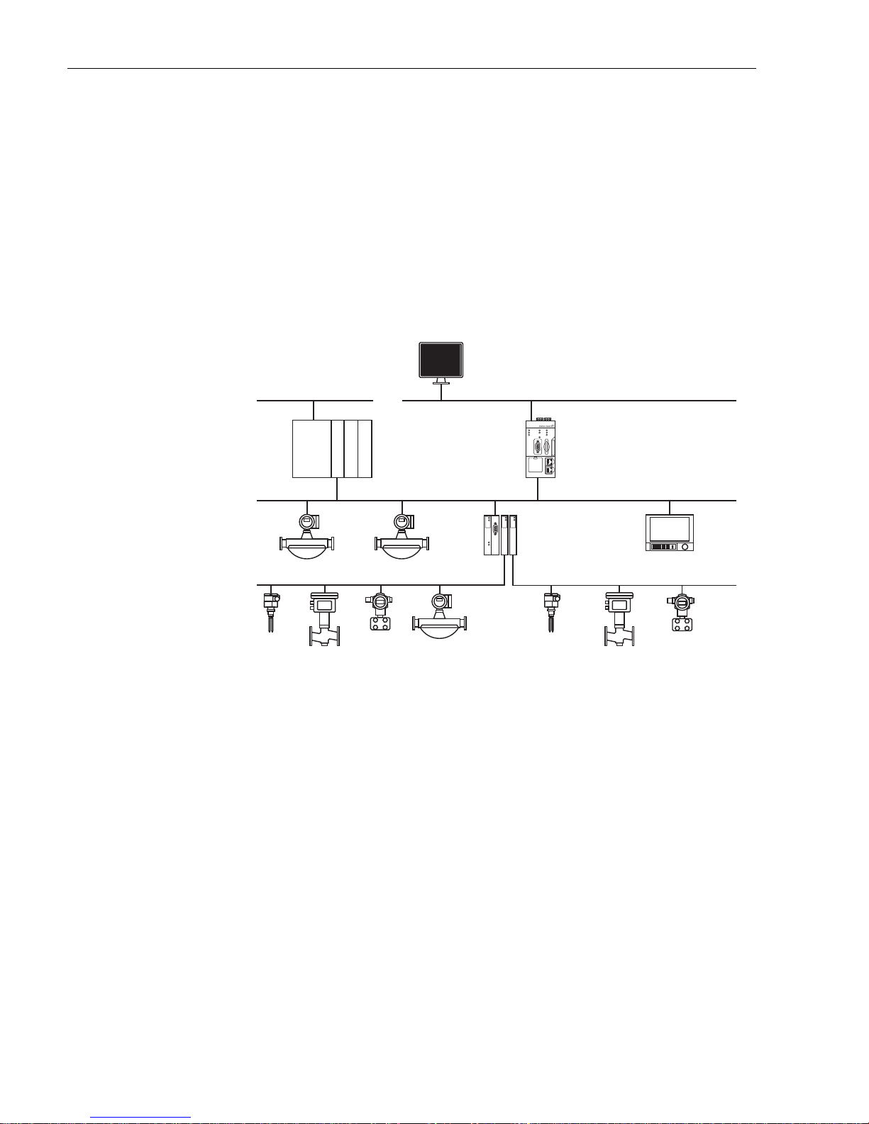
4.1.1 Architecture
When operating with a single segment with Pepperl+Fuchs coupler, the component
architecture is for example as shown in Fig. 4.1. Fieldgate SFG500 is connected to the
Ethernet backbone via the LAN 1 Ethernet socket and to the PROFIBUS DP segment. The
segment itself is connected to a PLC or DCS, which acts as Class 1 master. PROFIBUS PA
devices are connected to the network via the coupler.
Fig. 4-1: Architecture for single segment
To see all the devices on the PROFIBUS DP/PA segment, FieldCare requires:
• SFGNetwork DTM
• All Device DTMs
PLC/
DCS
PB Master Class 1
DP/PA Coupler
Control Network LAN 1 (Ethernet)
FieldCare
PROFIBUS DP (Segment 1)
SFG500
Access Point
RS485
LAN 1
LAN 2
PB DP
PB Err
Reset
Power
Run
Failure
LAN 1
LAN 2
AB001CF2897L
SFG500
PROFIBUS PA
PROFIBUS PA
Page 13

Fieldgate SFG500 FieldCare
Endress+Hauser 11
4.1.2 Create a FieldCare project
1. Open FieldCare by a double click on its desktop icon
– If necessary enter the user name and password
2. Press Continue to close the introductory page:
3. Press Open to create a project
4. A project is created
Page 14

FieldCare Fieldgate SFG500
12 Endress+Hauser
4.1.3 Add the SFGNetwork CommDTM
1. In the network view, right click on Host and select Add Device:
2. The CommDTM catalog opens
– Select SFGNetwork
– Press OK to add the CommDTM to the Host
3. The SFGNetwork CommDTM is added to the Network view
Page 15

Fieldgate SFG500 FieldCare
Endress+Hauser 13
4.1.4 Scan for Fieldgate SFG500
1. Right-click on the SFGNetwork node and select Connect to put the CommDTM online
– The Connection arrows turn green
2. Right-click on the SFC500 Network node and select Create Network
3. FieldCare searches for any SFG500s in the Ethernet network and adds them to the
network view
4. If only one is found, it connects and opens the SFG500 CommDTM
5. If no DTM is found, it is possible that the UDP ports are blocked
– Either unblock as described in Appendix B (you will need administrator rights)
– Or add the CommDTM manually (right-click on SFG500 Network node, Add Device)
and configure it by hand, see Chapter 5.1
Page 16

FieldCare Fieldgate SFG500
14 Endress+Hauser
4.1.5 Scan for devices
1. Right-click on the SFG500 node and select Create Network
2. FieldCare scans the PROFIBUS segment to which Fieldgate SFG500 is connected for
devices
– All devices found are added to the network
– If any of the devices has a DTM of quality less than "1", the Scanning Result dialog
opens and OK must be pressed before the devices are added to the network
3. If only one device is found, its DTM will be opened automatically
– If more than one device is found, and the "Connect after scanning" option is selected
in Extras... , the message below must be acknowledged with OK, and the device
DTMs must be opened manually
Page 17

Fieldgate SFG500 FieldCare
Endress+Hauser 15
4.1.6 Open a device DTM
1. Right-click on the node of the device you want to open and select Connect
– The communication arrows turn green to indicate that it is online
2. Right-click on the node of the device again and select Online Parametrize
3. The DTM of the selected device is opened
– The device can now be configured according to the instructions in its operating
manual
Page 18

FieldCare Fieldgate SFG500
16 Endress+Hauser
4.1.7 Store the project
1. Right-click on the File menu and select Save
– The Save Project As window appears
– Enter a name for the project and press Save
2. The project can now be opened from the Existing tab in the project window that opens
when FieldCare is started
Page 19

Fieldgate SFG500 FieldCare
Endress+Hauser 17
4.2 Multiple segments with transparent couplers
4.2.1 Architecture
When operating with multiple segments and Pepperl+Fuchs couplers the component
architecture might be as for example as shown in Fig. 4.2. For simplicity the devices
connected to Segments
2 – 5 are not shown. All Fieldgate SFG500s are connected to the Ethernet backbone via the
LAN 1 Ethernet socket and share a common Ethernet IP address domain. One Fieldgate
SFC500 is connected to each PROFIBUS DP segment. The PROFIBUS DP segments do not
necessarily have to be connected to a single PLC. PROFIBUS PA devices are connected to the
PROFIBUS DP segments via couplers.
Fig. 4-1: Architecture for multiple segments
To see all the devices on the PROFIBUS DP/PA segment, FieldCare requires:
• SFGNetwork DTM
• All Device DTMs
PLC/
DCS
PB Master Class 1
Control Network LAN 1 (Ethernet)
FieldCare
PROFIBUS DP
Access
Points
PB Master Class 1
PB Master Class 1
PB Master Class 1
PB Master Class 1
Segment 1
Segment 2
Segment 3
Segment 4
Segment 5
RS485
LAN 1
LAN 2
PB DP
PB Err
Reset
Power
Run
Failure
LAN 1
LAN 2
AB001CF2897L
SFG500
RS485
LAN 1
LAN 2
PB DP
PB Err
Reset
Power
Run
Failure
LAN 1
LAN 2
AB001CF2897L
SFG500
RS485
LAN 1
LAN 2
PB DP
PB Err
Reset
Power
Run
Failure
LAN 1
LAN 2
AB001CF2897L
SFG500
RS485
LAN 1
LAN 2
PB DP
PB Err
Reset
Power
Run
Failure
LAN 1
LAN 2
AB001CF2897L
SFG500
RS485
LAN 1
LAN 2
PB DP
PB Err
Reset
Power
Run
Failure
LAN 1
LAN 2
AB001CF2897L
SFG500
DP/PA Coupler
PROFIBUS PA
PROFIBUS PA
Page 20

FieldCare Fieldgate SFG500
18 Endress+Hauser
4.2.2 Create a FieldCare project
NOTE!
• The dialogs for this procedure are identical to those in Chapter 4.1.2
1. Open FieldCare by a double click on its desktop icon
– If necessary enter the user name and password
2. Press Continue to close the introductory page:
3. Press Open to create a project
4. A project is created
4.2.3 Add the SFGNetwork CommDTM
NOTE!
• The dialogs for this procedure are identical to those in Chapter 4.1.3
1. In the network view, right click on Host and select Add Device:
2. The CommDTM catalog opens
– Select SFGNetwork
– Press OK to add the CommDTM to the Host
3. The SFGNetwork CommDTM is added to the Network view
4.2.4 Scan for Fieldgate SFG500
NOTE!
• The dialogs for this procedure are identical to those in Chapter 4.1.4
1. Right-click on the SFGNetwork node and select Connect to put the CommDTM online
– The Connection arrows turn green
2. Right-click on the SFC500 Network node and select Create Network
3. FieldCare searches for any SFG500s in the Ethernet network
– If the "Connect after scanning" option is selected in Extras... , the message below must
be acknowledged with OK, as more than one Fieldgate SFG500 has been found
4. FieldCare adds the Fieldgate SFG500s found to the network view
5. If no DTM is found, it is possible that the UDP ports are blocked
– Either unblock as described in Appendix B (you will need administrator rights)
– Or add the CommDTM manually (right-click on SFG500 Network node, Add Device)
and configure it by hand, see Chapter 5.1
Page 21

Fieldgate SFG500 FieldCare
Endress+Hauser 19
4.2.5 Scan for devices
1. Select a SFG500 node, right-click on it and select Connect
2. Right-click on the connected SFG500 node and select Create Network
3. FieldCare scans the PROFIBUS segment to which Fieldgate SFG500 is connected for
devices
– If any of the devices has a DTM of quality less than "1", the Scanning Result dialog
opens and OK must be pressed before the devices are added to the network
– If more than one device is found, and the "Connect after scanning" option is selected
in Extras... , the Connect after scanning message below must be acknowledged
with OK. All devices found are then added to the network view
– If only one device is found, and the "Connect after scanning" option is selected in
Extras... (default setting), FieldCare adds it to the network view, connects and opens
the DeviceDTM
4. Repeat Steps 1 to 3 for all other Fieldgates that were found
5. The Device DTMs can be opened and the project stored as described in Chapters 4.1.6
and 4.1.7 respectively
Page 22

FieldCare Fieldgate SFG500
20 Endress+Hauser
4.3 Segment with Siemens link
4.3.1 Architecture
When operating with a Siemens DP/PA Coupler or Link, the component architecture might
be as for example as shown in Fig. 4.3. The Fieldgate SFG500 is connected to the Ethernet
backbone via the LAN 1 Ethernet socket. PROFIBUS PA devices are connected to the network
via the Siemens Coupler/Link.
Fig. 4-1: Architecture for Siemens coupler/link
To see all the devices on the PROFIBUS DP/PA segment, FieldCare requires:
• SFGNetwork DTM
• Licensed Trebling and Himstedt CommDTM DP/PA link
• All Device DTMs
PLC/
DCS
PB Master Class 1
Siemens Link/
DP/PA Coupler
PROFIBUS PA
Control Network LAN 1 (Ethernet)
FieldCare
PROFIBUS DP (Segment 1)
SFG500
Access Point
RS485
LAN 1
LAN 2
PB DP
PB Err
Reset
Power
Run
Failure
LAN 1
LAN 2
AB001CF2897L
SFG500
Page 23

Fieldgate SFG500 FieldCare
Endress+Hauser 21
4.3.2 Create a FieldCare project
NOTE!
• The dialogs for this procedure are identical to those in Chapter 4.1.2
1. Open FieldCare by a double click on its desktop icon
– If necessary enter the user name and password
2. Press Continue to close the introductory page:
3. Press Open to create a project
4. A project is created
4.3.3 Add the SFGNetwork CommDTM
NOTE!
• The dialogs for this procedure are identical to those in Chapter 4.1.3
1. In the network view, right click on Host and select Add Device:
2. The CommDTM catalog opens
– Select SFGNetwork
– Press OK to add the CommDTM to the Host
3. The SFGNetwork CommDTM is added to the Network view
4.3.4 Scan for Fieldgate SFG500
NOTE!
• The dialogs for this procedure are identical to those in Chapter 4.1.4
1. Right-click on the SFGNetwork node and select Connect to put the CommDTM online
– The Connection arrows turn green
2. Right-click on the SFC500 Network node and select Create Network
3. FieldCare searches for any SFG500s in the Ethernet network and adds them to the
network view
4. If only one Fieldgate is found, its DTM is opened automatically
5. If no DTM is found, it is possible that the UDP ports are blocked
– Either unblock as described in Appendix B (you will need administrator rights)
– Or add the CommDTM manually (right-click on SFG500 Network node, Add Device)
and configure it by hand, see Chapter 5.1
Page 24

FieldCare Fieldgate SFG500
22 Endress+Hauser
4.3.5 Scan for the Coupler/Link
1. If necessary, select the SFG500 node, right-click on it and select Connect
2. Right-click on the connected SFG500 node and select Create Network
3. FieldCare scans the PROFIBUS segment to which Fieldgate SFG500 is connected for the
Siemens Link
– The Create Network – Scanning result dialog opens
– Press OK to add the DP/PA Link CommDTM to the network
4. The DP/PA Link CommDTM is added to the Network view
– If only one device is found, and the "Connect after scanning" option is selected in
Extras... (default setting), FieldCare adds it to the network view, connects and opens
the DTM
– If more than one device is found, and the "Connect after scanning" option is selected
in Extras..., the Connect after scanning message below must be acknowledged
with OK. All devices found are then added to the network view
Page 25

Fieldgate SFG500 FieldCare
Endress+Hauser 23
4.3.6 Scan for devices
1. If necessary, select the DP/PA Link node, right-click on it and select Connect
2. Right-click on the connected DP/PA Link node and select Create Network
3. FieldCare scans the segment to which the DP/PA Link is connected for devices
– The Create Network – Scanning result dialog opens
– Press OK to add the devices to the network
4. If the "Connect after scanning" option is selected in Extras... , the message below must be
acknowledged with OK, as more than one device has been found
5. The devices are added to the Network view
6. The Device DTMs can be opened and the project stored as described in Chapters 4.1.6
and 4.1.7 respectively
Page 26

FieldCare Fieldgate SFG500
24 Endress+Hauser
4.4 Segment with Stahl Remote I/O
4.4.1 Architecture
When operating with a Stahl CPM 9440 Remote I/O, the component architecture might be
as for example as shown in Fig. 4.4. The Fieldgate SFG500 is connected to the Ethernet
backbone via the LAN 1 Ethernet socket. PROFIBUS PA devices are connected to the network
via e.g. a transparent coupler. The 4–20 mA/HART devices are connected point-to-point to
the Stahl Remote I/O, which in turn is connected to the PROFIBUS DP segment.
Fig. 4-1: Architecture for Stahl remote I/O
To see all the devices on the PROFIBUS DP/PA segment, FieldCare requires:
• SFGNetwork DTM
• Licensed Stahl CommDTM CPM 9440
• All PROFIBUS Device DTMs
• All HART Device DTMs
PLC/
DCS
PB Master Class 1
DP/PA Coupler
Control Network LAN 1 (Ethernet)
FieldCare
PROFIBUS DP (Segment 1)
SFG500
Access Point
RS485
LAN 1
LAN 2
PB DP
PB Err
Reset
Power
Run
Failure
LAN 1
LAN 2
AB001CF2897L
SFG500
PROFIBUS PA
Stahl CPM 9440
Remote I/O
4–20 mA/HART
Page 27

Fieldgate SFG500 FieldCare
Endress+Hauser 25
4.4.2 Create a FieldCare project
NOTE!
• The dialogs for this procedure are identical to those in Chapter 4.1.2
1. Open FieldCare by a double click on its desktop icon
– If necessary enter the user name and password
2. Press Continue to close the introductory page:
3. Press Open to create a project
4. A project is created
4.4.3 Add the SFGNetwork CommDTM
NOTE!
• The dialogs for this procedure are identical to those in Chapter 4.1.3
1. In the network view, right click on Host and select Add Device:
2. The CommDTM catalog opens
– Select SFGNetwork
– Press OK to add the CommDTM to the Host
3. The SFGNetwork CommDTM is added to the Network view
4.4.4 Scan for Fieldgate SFG500
NOTE!
• The dialogs for this procedure are identical to those in Chapter 4.1.4
1. Right-click on the SFGNetwork node and select Connect to put the CommDTM online
– The Connection arrows turn green
2. Right-click on the SFC500 Network node and select Create Network
3. FieldCare searches for any SFG500s in the network and adds them to the network view
4. If only one Fieldgate is found, its DTM is opened automatically
5. If no DTM is found, it is possible that the UDP ports are blocked
– Either unblock as described in Appendix B (you will need administrator rights)
– Or add the CommDTM manually (right-click on SFG500 Network node, Add Device)
and configure it by hand, see Chapter 5.1
Page 28

FieldCare Fieldgate SFG500
26 Endress+Hauser
4.4.5 Scan for the Stahl Remote I/O
1. If necessary, select the SFG500 node, right-click on it and select Connect
2. Right-click on the connected SFG500 node and select Create Network
3. FieldCare scans the PROFIBUS segment to which Fieldgate SFG500 is connected for the
Remote I/O
– The Create Network – Scanning result dialog opens
– Press OK to add the Stahl CPM 9440 CommDTM to the network
4. The CPM 9440 CommDTM is added to the Network view
– If only one device is found, and the "Connect after scanning" option is selected in
Extras... (default setting), FieldCare adds it to the network view, connects and opens
the DTM
– If more than one device is found, and the "Connect after scanning" option is selected
in Extras... , the Connect after scanning message below must be acknowledged
with OK. All devices found are then added to the network view
Page 29

Fieldgate SFG500 FieldCare
Endress+Hauser 27
4.4.6 Scan for devices
1. If necessary, select the CPM 9440 node, right-click on it and select Connect
2. Right-click on the connected CPM 9440 node and select Create Network
3. The Select Communication Channel dialog appears
– Press OK to scan all channels of the Remote I/O
4. The devices found are added to the Network view
– If only one device is found, and the "Connect after scanning" option is selected i
n Extras... (default setting), FieldCare adds it to the network view, connects and
opens the DTM
– If more than one device is found, and the "Connect after scanning" option is selected
in Extras... , the Connect after scanning message below must be acknowledged
with OK. All devices found are then added to the network view
5. The Device DTMs can be opened and the project stored as described in Chapters 4.1.6
and 4.1.7 respectively
6. The CPM 9440 DTM also provides an overview of the connected HART devices
– Right-click on the CPM node and select Additional Functions=>HART Live List
Page 30

DTM for Fieldgate SFG500 Fieldgate SFG500
28 Endress+Hauser
5 DTM for Fieldgate SFG500
This chapter contains a short description of the functions obtainable via the Fieldgate
SFG500 Device DTM. All functions are called by right-clicking on a connected DTM and
selecting the appropriate context menu. This procedure is not illustrated by screenshots.
5.1 Configuration
5.1.1 Fieldgate SFG500 CommDTM
NOTE!
• The identification parameters can be changed only when Fieldgate SFG500 is offline
The configuration menu opens the Fieldgate SFG500 CommDTM.
1. Right-click on the SFG500 node and select Configuration
– The SFG500 Device DTM opens:
2. The parameters have the following significance:
Parameter Meaning
Identification If the SFG500 Device DTM is added manually to a network, the drop down menu allows
three ways of identifying the device to which the DTM is to be connected.
• Serial Number: The Serial Number entry box is enabled.
– Enter the serial number of the associated device and press Enter
– The connection is made and the IP address and Device Tag are displayed
• IP Address: The IP Address entry box is enabled
– Enter the IP address of the associated device and press Enter
– The connection is made and the serial number and Device Tag are displayed
• Device Tag: The Device Tag entry box is enabled
– Enter the device tag of the associated device and press Enter
– The connection is made and the serial number and IP address are displayed
Serial Number Displays the serial number of the connected device
• When offline, the box can also be used to reconnect to a different device, see above
IP Address Displays the IP address of the connected device
• When offline, the box can also be used to reconnect to a different device, see above
Device Tag Displays the Device Tag of the connected device.
• When offline, the box can also be used to reconnect to a different device, see above
• When online, the box can be used to change the tag of the connected device
Start Address PROFIBUS address from which Fieldgate SFG500 starts scanning for devices on the bus
–Default value = 0
End Address PROFIBUS address at which Fieldgate SFG500 stops scanning for devices on the bus
– Default value = 126
Page 31

Fieldgate SFG500 DTM for Fieldgate SFG500
Endress+Hauser 29
5.1.2 Proxy Server Configuration
NOTE!
• The proxy can be changed only when Fieldgate SFG500 is offline
Some dialogs of the SFG500 CommDTM are Web pages provided by the connected Fieldgate
SFG500. In order to connect to the Web server, it may be necessary to configure the proxy
server.
1. The proxy server is configured in the advanced settings of the configuration dialog.
These are selected by enabling the tree view of the dialogue with the leftmost button in
the toolbar.
2. The options in the drop-down menu are as follows:
Parameter Meaning
automatic (default) First the system settings are used. If this does not work, option no Proxy Server is used
system settings The settings defined in the Web browser are used
no proxy The proxy server is disabled
Page 32

DTM for Fieldgate SFG500 Fieldgate SFG500
30 Endress+Hauser
5.2 Embedded Web Server
The Embedded Web Server menu presents all functions provided by the Fieldgate Web
Server in a DTM environment.
1. If not already done, right-click on the SFG500 node and select Connect to put the
Fieldgate DTM online
2. Right-click on the SFG500 node and select Additional Functions =>Embedded Web
Server
– The PROFIBUS Live List window opens
3. Navigate through the menus by clicking on the Tabs or the sub-menu items
– The number of tabs that appear depends upon whether Fieldgate Module SFM500
is in use and the functions that it supports
Page 33

Fieldgate SFG500 DTM for Fieldgate SFG500
Endress+Hauser 31
5.2.1 PROFIBUS live list
The PROFIBUS live list shows all devices that can be seen by the selected Fieldgate SFG500
when it is listening to the bus. If the listener was active during the initialization of the slaves,
the slave ID is shown.
Grid View 1. Right-click on the SFG500 node and select Additional Functions =>Embedded Web
Server then click on the Network tab.
2. Click on PROFIBUS live list
– The SFG500 PROFIBUS Live List window opens:
3. The various elements have the following significance:
Element Meaning
Overview table Indicates the number of devices on the bus, together with their type and status
• Green: Device in cyclic data exchange, status OK
• Yellow: Device in cyclic data exchange, has diagnostic message
• Orange: Device failed to enter into cyclic data exchange
• Grey: Device is present, but not in cyclic data exchange
• Blue: Fieldgate SFG500
Show List View/
Show Grid View
Toggles between a grid and list view of the connected devices
Live list matrix Indicates the type and PROFIBUS address of the slave
• Mxxx: master with PROFIBUS address xxx
• Syyy: slave with PROFIBUS address yyy
• Colour code: as in overview
Page 34

DTM for Fieldgate SFG500 Fieldgate SFG500
32 Endress+Hauser
List View 4. Click on Show List View to display a list of connected devices
– Click on a device to show its details
– Click on Show Grid View to return to the view above
5. The various elements have the following significance:
Element Meaning
Overview table Indicates the number of devices on the bus, together with their type and status
• Green: Device in cyclic data exchange, status OK
• Yellow: Device in cyclic data exchange, has diagnostic message
• Orange: Device failed to enter into cyclic data exchange
• Grey: Device is present, but not in cyclic data exchange
• Blue: Fieldgate SFG500
Show Grid View/
Show List View
Toggles between a grid and list view of the connected devices
Live list
Slave Slave ID in PROFIBUS live list (Saaa, aaa = PROFIBUS address)
Ident Slave device type
Device Type Manufacturer’s device type identification
Serial No. Manufacturer’s serial number of the slave
Tag Tag No. of the slave
Status Status
• OK: No events since last restart of live list
• DIAG: Device has issued a diagnostic message since last restart of live list
• FAIL: Device has failed since last restart of live list
Details of Slave
Vendor Manufacturer or vendor of the selected slave
HW Revision Hardware revision of the selected slave
SW Revision Software revision of the selected slave
Page 35

Fieldgate SFG500 DTM for Fieldgate SFG500
Endress+Hauser 33
5.2.2 PROFIBUS Monitor
1. Right-click on the SFG500 node and select Additional Functions =>Embedded Web
Server then click on the Network tab.
2. Click on PROFIBUS Monitor
– The PROFIBUS Monitor window opens:
3. The parameters have the following significance:
Parameter Meaning
Restart Restarts the PROFIBUS Monitor
Diagnostic table
Slave
Ident Slave device type
Status Status:
• OK: No events since last restart of monitor
• DIAG: Device has issued a diagnostic message since last restart of monitor
• FAIL: Device has failed since last restart of monitor
Init Indicates the number of device initializations since the last restart of monitor
Diag Indicates the number of diagnostic messages since the last restart of monitor
Last Diagnosis Time Indicates the time of the last diagnostic message issued by the device
– If there has been no message, the time of the last monitor restart is shown
Details of Slave
Parameter String Parameter string of selected slave (shown only after an initialization)
Config String Configuration string of selected slave (shown only after an initialization)
Last Diagnosis Diagnosis string of selected slave (shown only after an diagnostic message)
Page 36

DTM for Fieldgate SFG500 Fieldgate SFG500
34 Endress+Hauser
5.2.3 PROFIBUS Settings
NOTE!
• The set up of Fieldgate SFG500 is described in Chapter 7.2.7 of Operating Instructions
BA00070S/04/en, Fieldgate SFG500 Installation and Commissioning
The PROFIBUS settings list shows the detected baudrate, the PROFIBUS address of the
selected Fieldgate and detected bus parameters used by the Class 1 master. The window can
be used to change the bus parameters, however, it is important to note that all the PROFIBUS
DP devices, including couplers and links, connected to a particular network must have the
same communication settings
1. Right-click on the SFG500 node and select Additional Functions =>Embedded Web
Server then click on the Network tab
2. Click on PROFIBUS Settings
– The SFG500 PROFIBUS Settings window opens:
3. The parameters have the following significance:
Parameter Description
Configuration Mode
Auto Mode Fieldgate SFG500 detects the PROFIBUS parameters and sets its own address
– The detected PROFIBUS parameters are displayed
– Overwriting is disabled
Passive Mode Fieldgate SFG500 listens to the bus but does not enter traffic as Master Class 2
– FieldCare cannot be used with this mode
Manual Mode Writing is enabled and the user can set the PROFIBUS parameters
– Fieldgate must use the same parameters as all other PROFIBUS equipment
otherwise communication will fail
– A return to manual mode will cause all changes to be lost and Fieldgate will
detect the PROFIBUS parameter and set its own address
Baudrate
Baudrate Indicates the baudrate detected by Fieldgate SFG500
• To change the baudrate:
–Select Manual mode
– Select a new baudrate from the pull-down menu and press Apply
– If the baudrate is in conflict with the one used by the master, a message
appears
–Selecting
Auto mode will cause all changes to be lost
Page 37

Fieldgate SFG500 DTM for Fieldgate SFG500
Endress+Hauser 35
Address Parameters
Station Address Fieldgate SFG500 PROFIBUS DP address (Master Class 2) that it has assigned
automatically to itself after listening to the bus
• To force a new address (0 – 126):
– Select Manual mode
– Enter a new unoccupied address press Apply
– Selecting Auto mode will cause all changes to be lost
Highest Station Address Indicates the address range that is scanned for token passing.
Timing Parameters
Slot Time Monitoring time – 'Wait for receipt' – of the senders (Requestor) of telegram for
the acknowledgement of the recipient (Responder). After expiration, a retry occurs
in accordance with the value of 'Max. telegram retries'.
Min. Station Delay Time Shortest time period that must elapse before a remote recipient (Responder) may
send an acknowledgement of a received query telegram.
The shortest time period between receipt of the last Bit of a telegram to the
sending of the first Bit of a following telegram.
Max. Station Delay Time Longest time period that must elapse before a Sender (Requestor) may send a
further query telegram.
Greatest time period between receipt of the last Bit of a telegram to the sending of
the first Bit of a following telegram.
The Sender (Requestor, Master) must wait at least for this time period after the
sending of an unacknowledged telegram (e.g. Broadcast only) before a new
telegram is sent.
Quiet Time Time delay that occurs for modulators (Modulator-trip time) and Repeaters
(Repeater-switch time) for the change over from sending to receiving.
Setup Time Minimum period "reaction time" between the receipt of an acknowledgement to the
sending of a new query telegram (Reaction) by the Sender (Requestor).
Token Rotation Time Pre-set nominal Token cycling time within which the Sender authorization (Token)
will cycle around the ring. How much time the Master still has available for sending
data telegrams to the Slaves is dependent on the difference between the nominal
and the actual token cycling time.
Gap Update Factor Factor for determining after how many Token cycles an added participant is
accepted into the Token ring. After expiry of the time period G*TTR, the Station
searches to see whether a further participant wishes to be accepted into the logical
ring.
Max Retries Limit Number of times the Fieldgate will try to establish communication with a device
before it flags it as faulty
Button
Apply Applies any changes to Fieldgate SFG500
Parameter Description
Page 38

DTM for Fieldgate SFG500 Fieldgate SFG500
36 Endress+Hauser
5.2.4 Slave Settings
Slave Settings allows the user to change the address of the selected PROFIBUS device, e.g.
during commissioning of the network. It has exactly the same function as Set Device
Address, see Chapter 5.3.2.
1. Right-click on the SFG500 node and select Additional Functions =>Embedded Web
Server then click on the Network tab
2. Click on Slave Settings
– The PROFIBUS slave settings window opens:
3. Select the address of the device whose address must be changed from the Current
Address drop-down menu
4. Select the address the device should be given in the New Address drop-down menu
5. Press Apply to write the change of address to the device
– Pressing Cancel will discard all changes and leave the device with its old address
– A possible reason for a failure to change an address is that the device is locked
6. After an address change the device concerned will no longer be connected to its DTM:
– Either change the DTM address to the new device address, see Chapter 5.3.3 or
– Delete all the devices below the SFG500 and create the network again
Page 39

Fieldgate SFG500 DTM for Fieldgate SFG500
Endress+Hauser 37
5.2.5 Settings and Information tabs
Settings tab The settings tab allows the IP address and time and date of Fieldgate SFG500 to be changed.
Normally these parameters will be adjusted during the commissioning of Fieldgate SFG500
as described in Chapter 7.2.6 of Operating Instructions BA00070S/04/en, Fieldgate
SFG500 Installation and Commissioning. The firmware update is described in Chapter 8.2.3
of the same manual.
Information tab The Information tab displays the information stored on the Electronic nameplate of
Fieldgate SFG500 and where of Fieldgate Module SFM500.
Page 40

DTM for Fieldgate SFG500 Fieldgate SFG500
38 Endress+Hauser
5.3 Additional Functions
5.3.1 Communication log
The communication log provides a record of the transactions on the PROFIBUS network and
can be used in diagnosing communication faults. It starts automatically on call up.
1. Right-click on the SFG500 node and select Additional Functions => Communication
log
– The SFG500 Communication log window opens:
– Click the Settings tab to set what is to be logged
2. The various buttons and parameters have the following significance:
Parameter group Meaning
Logging tab Shows the communication log.
– Starts automatically on call up
– After a log has been cleared, press the Start button to restart the logging
Settings tab Sets the filters for the events to be logged
• Information: logs all information messages
• Warning: logs all warning messages
• Error: logs all error messages
• Comment: Logs all comments
• Status: logs all status messages
Start Starts the log again after it has been cleared
Clear Deletes the current log and stops logging
Save Saves the current log
–In the Save as page which opens, navigate to the desired folder
–Enter a file name then press
Save
Page 41

Fieldgate SFG500 DTM for Fieldgate SFG500
Endress+Hauser 39
5.3.2 Set Device Address (PB Address)
Set Device Address allows the user to change the address of the selected PROFIBUS device,
e.g. during commissioning of the network.
1. Right-click on the SFG500 node and select Additional Functions => Set Device
Address
– The PROFIBUS slave settings window opens:
2. Select the address of the device whose address must be changed from the Current
Address drop-down menu
3. Select the address the device should be given in the New Address drop-down menu
4. Press Apply to write the change of address to the device
– Pressing Cancel will discard all changes and leave the device with its old address
– A possible reason for a failure to change an address is that the device is locked
5. After an address change the device concerned will no longer be connected to its DTM:
– Either change the DTM address to the new device address, see Chapter 5.3.3 or
– Delete all the devices below the SFG500 and create the network again
Page 42

DTM for Fieldgate SFG500 Fieldgate SFG500
40 Endress+Hauser
5.3.3 Set DTM Address (DTM)
Set DTM Addresses allows the user to match the addressing in the DTM, i.e. the Tag in
PROFIBUS networks, to the physical devices. The function is not relevant to FieldCare as this
is done during a network scan but might be required for other FDT frames.
1. Right-click on the SFG500 node and select Additional Functions => Set DTM Address
– The SFG500 Set DTM address window opens:
2. The various buttons and parameters have the following significance:
Parameter group Meaning
Device Name Shows the device and firmware version associated with the DTM
Device Tag Shows the device tag of each device connected to the selected Fieldgate SFG500
– To change a device tag, enter the new designation then press
Update
Address Shows the PROFIBUS address of each device connected to the selected Fieldgate
SFG500
– To change an address, enter the new designation then press
Update
– The same change must now be made in the Set Device Address dialog otherwise
the connection to the device will be broken, see on-line help
Update Downloads the any changes in device tag or address to the DTM
Page 43

Fieldgate SFG500 DTM for Fieldgate SFG500
Endress+Hauser 41
5.3.4 Help
Help provides instructions on the functions and use of the SFG500 DTM
1. Right-click on the SFG500 node and select Additional Functions => Help
– The SFG500 Help opens:
2. Navigate to the topic of interest
5.3.5 About
About gives information about Fieldgate SFG500 and its Device DTM.
1. Right-click on the SFG500 node and select Additional Functions => About
– The SFG500 About window opens:
Page 44

Trouble-Shooting Fieldgate SFG500
42 Endress+Hauser
6 Trouble-Shooting
6.1 FieldCare
Problem Cause/Remedy
1 SFGNetwork DTM not available in DTM library • FieldCare version does not support SFG500
– Install Fieldgate DTMs from CD-ROM supplied
–Update DTM catalogue
3 SFGNetwork DTM cannot find Fieldgate SFG500 • No connection (general)
– Check all Ethernet connections
– Check that Fieldgate SFG500 is switched on
– Check that the IP address domain of the computer
is the same as that for Fieldgate SFG500
(a simple test is to call the web server or ping)
– Check that there is no firewall blocking
communication
– Check that the Microsoft SQL Server is running
• No connection after network scan (additional
remedies)
– Check that PC and SFG500 are in the same logical
network (ping)
– If not, check that the following ports are enabled
on the router (see also Appendix B)
UDP 60020: from SFG500 network to PC
TCP 60010: in both directions
• No connection after manual connect (additional
remedies)
– Check any error messages in FieldCare
– Check the configuration of the CommDTM
is entered IP address, Tag, Serial number correct?
4 SFG500 DTM cannot find PROFIBUS device(s) • No connection
– Check all PROFIBUS connections
– Check that device is switched on
– Check that the device has a unique PROFIBUS
address
– Check that the bus is properly terminated
5 Device(s) connected to link cannot be seen • No connection
– Check that the link CommDTM is in place and
property configured
– Check all PROFIBUS connections
– Check that device is switched on
– Check that the device has a unique PROFIBUS
address
– Check that the bus is properly terminated
6 Device(s) connected to a Remote I/O cannot be
seen
• No connection
– Check that the Remote I/O CommDTM is in place
and properly configured with licence
– Check all HART connections
– Check that device is switched on
Page 45

Fieldgate SFG500 Changing a computer’s IP properties
Endress+Hauser 43
Appendix A Changing a computer’s IP properties
NOTE!
• You may need administration rights to change the IP settings of your computer.
If this is the case, contact your system administrator
• The procedures described in this chapter are for Windows XP. For other Windows systems
consult your system administrator.
Most computers which are used in a company network will already be set up to accept an IP
address from a DHCP server. If you computer is used in a control system, however, it is
possible that it has a fixed address. In this case, in order to connect to Fieldgate SFG500’s
LAN2 port, proceed as follows:
Procedure for Windows XP 1. Right-click Start =>Settings =>Control Panel =>Network Connections
2. Right-click Local Area Connection => Properties
3. Using the left mouse button, double-click Internet Protocol (TCP/IP) or
click once, then click Properties.
4. Note the addresses that have been assigned to your computer - you will need them later
when you reset your computer after commissioning the Fieldgate SFG500, see below
Page 46

Changing a computer’s IP properties Fieldgate SFG500
44 Endress+Hauser
5. Select the option Obtain and IP address automatically
6. Now click OK to confirm your selection and close the dialog
– Press OK to close the Local Area Connection window
Resetting the fixed IP
address
After the Fieldgate SFG500 has been set up, you can reset your computer to its old address
as follows
7. Repeat Steps 1 to 3 of the above procedure
8. In the Internet Protocol (TCP/IP) Properties dialog select the option Use the
following IP address
– Re-enter the settings that you noted at Step 4
9. Now click OK to confirm your selection and close the dialog
– Press OK to close the Local Area Connection window
Page 47

Fieldgate SFG500 Changing a computer’s IP properties
Endress+Hauser 45
Appendix B Windows Firewall
If firewalls are in use on the computers on which the servers and clients reside, they must be
programmed to allow mutual access. As firewall configuration is often a matter of company
IT security policy, your system administrator should be consulted before proceeding. In
addition, administration rights are required to perform this task.
1. Press Start => Control Panel => Windows Firewall
2. Press the Exceptions tab to add the exceptions on two main levels:
– Add program..: specify which applications are able to respond to unsolicited requests
– Add Port..: specify that the firewall should allow TCP traffic at ports used by the
servers, see Table 4-1 below
3. In the General tab, select the On (recommended) radio button to switch on the firewall
Communication ports The ports available for Fieldgate SFG500 are listed in the table below:
Port number ID Meaning
TCP 60010 TCP_PCPS2_SFG500_PORT
UDP 60015 UDP_IDENTIFY_PORT
UDP 60020 UDP_ANNUNC_PORT
Page 48

Changing a computer’s IP properties Fieldgate SFG500
46 Endress+Hauser
For your notes
Page 49

Fieldgate SFG500 Changing a computer’s IP properties
Endress+Hauser 47
For your notes
Page 50

Fieldgate SFG500 Changing a computer’s IP properties
48 Endress+
Hauser
Index
D
Documentation . . . . . . . . . . . . . . . . . . . . . . . . . . . . . . . . . . . 3
F
FieldCare. . . . . . . . . . . . . . . . . . . . . . . . . . . . . . . . . . . . . . . 10
FieldCare DTM Catalog . . . . . . . . . . . . . . . . . . . . . . . . . . . . . 9
Fixed IP address . . . . . . . . . . . . . . . . . . . . . . . . . . . . . . . . . 44
I
Information tab . . . . . . . . . . . . . . . . . . . . . . . . . . . . . . . . . 37
IP address . . . . . . . . . . . . . . . . . . . . . . . . . . . . . . . . . . . . . 6, 8
L
LAN1 port. . . . . . . . . . . . . . . . . . . . . . . . . . . . . . . . . . . . . 6, 8
LAN2 port. . . . . . . . . . . . . . . . . . . . . . . . . . . . . . . . . . . . . . . . 6
P
Pepperl+Fuchs coupler . . . . . . . . . . . . . . . . . . . . . . . . 10, 17
PROFIBUS Live List . . . . . . . . . . . . . . . . . . . . . . . . . . . . . . 30
PROFIBUS Monitor . . . . . . . . . . . . . . . . . . . . . . . . . . . . . . 33
PROFIBUS Settings . . . . . . . . . . . . . . . . . . . . . . . . . . . . . . 34
S
Safety . . . . . . . . . . . . . . . . . . . . . . . . . . . . . . . . . . . . . . . . . . . 3
Settings tab. . . . . . . . . . . . . . . . . . . . . . . . . . . . . . . . . . . . . 37
SFG500 DTM
About. . . . . . . . . . . . . . . . . . . . . . . . . . . . . . . . . . . . . . . 41
Additional Functions . . . . . . . . . . . . . . . . . . . . . . . . . . 38
Communication log . . . . . . . . . . . . . . . . . . . . . . . . . . . 38
Configuration . . . . . . . . . . . . . . . . . . . . . . . . . . . . . . . . 28
Diagnosis. . . . . . . . . . . . . . . . . . . . . . . . . . . . . . . . . . . . 30
Help . . . . . . . . . . . . . . . . . . . . . . . . . . . . . . . . . . . . . . . . 41
PROFIBUS live list . . . . . . . . . . . . . . . . . . . . . . . . . . . . 38
Profibus parameters . . . . . . . . . . . . . . . . . . . . . . . . . . 38
Set Device Address. . . . . . . . . . . . . . . . . . . . . . . . . . . . 39
Set DTM Address . . . . . . . . . . . . . . . . . . . . . . . . . . . . . 40
SFGNetwork DTM . . . . . . . . . . . . . . . . . . . 9–10, 17, 20, 24
Siemens link . . . . . . . . . . . . . . . . . . . . . . . . . . . . . . . . . . . . 20
Slave Settings . . . . . . . . . . . . . . . . . . . . . . . . . . . . . . . . . . . 36
Stahl Remote I/O . . . . . . . . . . . . . . . . . . . . . . . . . . . . . . . . 24
T
Trebling and Himstedt CommDTM DP/PA link. . . . . . . 20
W
Web browser . . . . . . . . . . . . . . . . . . . . . . . . . . . . . . . . . . . . . 7
Windows Firewall 45
Page 51

Page 52

www.addresses.endress.com
 Loading...